professional power amplifiers - toutlehautparleur.com · 3004-4004-4044-6004-6044. ......
TRANSCRIPT

OPERATION MANUAL
NOTICE D’EMPLOI
BEDIENUNGSANLEITUNG
P-7654-564QXPDQXDoc
4/06
© 2006 by C.E. Studio-2 s.l. - Spain (EEC)http://www.ramaudio.com
e-mail: [email protected]
Professional Power Amplifiers
S Series
1500-2000-3000-4000-60003004-4004-4044-6004-6044

WARNING:
The exclamation point inside anequilateral triangle indicates the existen-ce of internal components whose substi-tution may affect safety.
The lightning and arrowhead symbolwarns about the presence of uninsula-ted dangerous voltage.
To avoid fire or electrocution risk do notexpose the unit to rain or moisture.
To avoid electric shock, do not open theunit. No user serviciable parts inside. Inthe case of disfunction, have the unitchecked by qualified agents.
Class I device.
SAFETYPRECAUTIONS AVERTISSEMENTSSICHERHEITSHINWEISE
CAUTIONRISK OF ELECTRIC SHOCK
DO NOT OPEN
ACHTUNG!:
Das Ausrufezeichen innerhalb einesDreiecks weist darauf hin, dass derAustausch interner Bauteile dieSicherheit beeinflussen kann.
Das Blitzzeichen zeigt die Gegenwartunisolierter gefährlicher Spannungenan.
Um Brand oder elektrische Schläge zuvermeiden, darf diese Einheit keiner starken Luftfeuchtigkeit oderRegen ausgesetzt werden.
Um elektrische Schläge zu vermeiden,öffnen Sie diese Einheit nicht. BeiReparaturbedarf wenden Sie sich anqualifiziertes Personal.
Es handelt sich um ein Gerät derKlasse I.
1
VORSICHTGEFAHR EINES
ELEKTRISCHEN SCHLAGES.NICHT ÖFFNEN!
RÈGLES DE SÉCURITÉ:
Le trinagle ponctué du point d’exclama-tion central indique l’existence de com-posants internes affectant la sécurité depersonnes non agrées par nos S.A.V..
Le symbole éclair indique la présencede points électriques internes nonisolés.
Pour écarter tout risque d’incendie oud’électrocution, ne pas exposer l’appa-reil à la pluie ni à l’humidité.
Afin d’éviter tout risque, ne pas ouvrirl’appareil. Ne confier l’entretien de l’ap-pareil qu’à du personnel technique qua-lifié et agréé.
Appareil de Classe I.
ATTENTIONRISQUE DE CHOC ÉLECTRIQUE
NE PAS OUVRIR

0 Safety Precautions
1 General Information1.1 Introduction1.2 Main Characteristics
2 Controls: Where and What?2.1 Front Panel2.2 Rear Panel
3 Installation and Operation3.1 Connections3.1.1 Dual Channel Mode3.1.2 Link Channel Mode3.1.3 Bridge Channel Mode3.2 Configuration3.3 Troubleshooting
4 Technical Specifications4.1 Protection Systems4.2 Data
©2006 by C.E. Studio-2 s.l.Pol.Ind. La LlomaC/Sierra Perenxisa nº2846960 Aldaya - Valencia - SPAIN
Phone: +34 96 127 30 54Fax: +34 96 127 30 56
http://www.ramaudio.come-mail: [email protected]
P-7654-564 QXPDQXDoc 4/06
RAM Audio®, PMS™, SSP™, ICL™ andQuantaPulse™ are registered trade-marks of C.E. Studio-2 s.l.. All othernames are trademarks of their respecti-ve companies.
0 Sicherheitshinweise
1 Allgemeine Anweisungen1.1 Einleitung1.2 Allgemeine Eigenschaften
2 Lokalisierung der Funktionen2.1 Frontplatte2.2 Rückplatte
3 Anschluss- und Inbetriebnahme3.1 Anschlüsse3.1.1 Dual Kanalmodus3.1.2 Link Kanalmodus3.1.3 Bridge Kanalmodus3.2 Konfiguration3.3 Problemlösung
4 Technische Spezifikationen4.1 Schutzschaltungssysteme4.2 Technische Daten
INHALTSVERZEICHNISINDEX
0 Avertissements
1 Informations Générales1.1 Introduction1.2 Caractéristiques générales
2 Commandes et fonctions2.1 Panneau avant2.2 Panneau arrière
3 Installation et mise en route3.1 Branchements3.1.1 Mode DUAL3.1.2 Mode LINK3.1.3 Mode BRIDGE3.2 Configuration3.3 Dysfonctionnements éventuels
et dépannage.
4 Spécifications4.1 Systèmes de Protection4.2 Données téchniques
TABLE DESMATIÈRES
2

The S Series Power Amps is RAMAudio's response to our discerningclients' needs for a series of powerful,compact, versatile and rugged ampli-fiers characterised by no-compromiseelectronic and mechanical specifica-tions. The S Series range offers thebonus of optional add-on modules thatextend its operational capability tomatch any of today's market require-ments.
The S Series incorporate unique abso-
lute protections as the PMS™ or SSP™
systems.
• Instantaneous High Flow QuantaPulseEVO Power Supply.
• Ultra-compact and lightweight 2-Uhigh.
• Laser cut aluminum front panels withintegrated carrying handles.
• Neutrik® XLR input connectors, inputand signal link in 2 channel models.
• Input Link switch: allow daisy-chainingof the one channel input signal toanother adjacent channel.
• Neutrik® Speakon® output connectors.
• Detented sealed potentiometers foreasy recall of volume settings.
• ICL, PMS, Hi-temp, Signal indicatorsper channel.
• Highly versatile with multiple configu-ration possibilites and additionalmodule options.
• Switchable ICL clip-limiters per chan-nel.
• Switchable and selectable (30 or 50Hz) sub-sonic highpass filter perchannel.
• Three-position gain selector (26, 32 or38 dB).
• Dual or Bridge mode operation.
• Twin continuously variable, temperatu-re controlled, back to front coolingfans.
• Oversized power components (highSOA reserve specification).
1.2 Main Characteristics
1.1 Introduction
Die Endstufe S ist RAM Audios Antwortauf die Nachfrage unserer Kunden nachkompakten, leistungsstarken und gleich-zeitig vielseitigen und belastbarenEndstufen, die sich durch kompromiss-lose Elektronik und mechanischeAusführungen auszeichnen. Die S-Reihe bietet außerdem die Möglichkeitdie Leistungsfähigkeit der Endstufen mitoptionalen Erweiterungsmodulen auszu-bauen und so allen Anforderungen desMarktes zu genügen.
Die S-Reihe verfügt über einzigartigeSchutzsysteme wie PMS™ und SSP™.
• Quantapulse-Stromversorgung mitsofortigem Hochstrom.
• Ultrakompakt und leichtgewichtig, 2Uhoch.
• Lasergeschnittene Frontplatte mit inte-grierten Tragegriffen.
• Neutrik® XLR Eingangsstecker,Eingangs- und Signallink bei 2-Kanalmodellen.
• Eingangsverbindungsschalter: ermö-glicht die Verbindung des eingehen-den Signales eines Kanales mit einemanliegenden Kanal.
• Neutrik® Speakon® Ausgangsstecker.
• versiegelter Potentiometer mit 21Stufen für den einfachen Abruf vonVolumeneinstellungen.
• ICL-, PMS-, HI-Temp- undSignalanzeiger pro Kanal.
• Sehr vielseitig mit multiplenKonfigurationsmöglichkeiten undzusätzlichen Moduloptionen.
• schaltbare Cliplimiter pro Kanal.
• schaltbare und wählbare (30 oder50Hz) Subssonic-Hochpassfilter proKanal.
• 3-Punkt Gainselektor (26,32 oder38dB).
• Dual- oder Bridgemodusfunktion.
• Zwei temperaturkontrollierteKühlungsventilatoren die von derRückseite der Endstufe nach vorneblasen.
• Überdimensionale Leistungskom-ponenten (hohe SOA Reserve).
1.2 Allgemeine Eigenschaften
1.1 Einleitung
General Information
Les amplis de puissance de la Série Ssont en essence la réponse de RAMAudio aux besoins de nos clients, faceà une demande croissante des métiersdu son pour des appareils puissants,versatiles et résistants qui se caractéri-sent principalement par des spécifica-tions électroniques et mécaniques detrès haut niveau. La Série S offre enplus optionnellement, des modulesadditionnels qui accroissent leurs capa-cités opérationnelles pour faire face auxdemandes du marché actuel, sans limi-tes.La Série S incorpore aussi des systè-mes de protection absolue tels que: LePMS ou le SSP.
• Grande capacité en courant instan-tané QuantaPulse EVO.
• Ultra-compact et léger, 2-U en hau-teur.
• Face avant en alu découpée au laseravec poignées intégrées.
• Connecteurs d’entrée type XLRNeutrik® (doublés entrée-sortie pourmodèles de 2 canal).
• Commutateur d'entrée "Link" qui per-met la connection du signal d'un canalà l'autre.
• Neutrik® Speakon® de Sortie.
• Potentiomètres crantés et étanchespour un calage facile des niveaux.
• Signalisation par LED de ICL, PMS,Surchauffe et Signal.
• Versatilité augmentée avec possibilitéde configuration multiple et option demodules additionnels.
• Limiteurs d'écrêtage ICL commutablespar canal.
• Filtre passe-haut/subsonique commu-table aux 30 ou aux 50 Hz au choixpar canal.
• Trois niveaux de sensibilité au choix:26, 32 ou 38dB, (réglage usine 32dB).
• Conmutateur de mise en mode Bridgeou Dual sur le panneau arrière.
• Vitesse des ventilateurs asservie enfonction de la température interne.
• Modules de puissance munis de tran-sistors avec SOA amplement dimen-sionné.
1.2 Caractéristiques Générales
1.1 Introduction
InformationsGénérales
AllgemeineAnweisungen
3

Lokalisierung derFunktionen
See Figure
Signal attenuation level controlknobs: Permit independent controlof each channel’s attenuation (21steps).
SIGNAL: This LED indicates pre-sence of signal at the inputs.TEMP: This LED shows temperatu-re protection is active.PMS: LED indicating PMS in opera-tion (see page 10)ICL: LED indicating Intelligent ClipLimiter in operation (see page 10).
Main Power Switch:Position I: Connects the amplifier'scurrent feed. (Blue LED on).Position O disconnects the Power.Position II (optional): Stand-byMode. The Amp's Power is activatedremotely via Ethernet. (Amber LED).
3
2
2.1 Front Panel
1
1 Siehe Fig.
Lautstärkeregler: diese ermögli-chen die Signalstärke am Ausgangin 21 Stufen zu regeln.
SIGNAL: Wachanzeige des einge-henden Signals.TEMP: LED-Anzeige leuchtet wennder Schutz vor Überwärmung ein-geschaltet ist.PMS: Die LED zeigt an, dass dasPMS in Betrieb ist (siehe Seite 10)ICL: Die LED zeigt an, dass derIntelligent Cliplimiter arbeitet (sieheSeite 10).
Beleuchteter Hauptstromschalter:Position I: Schaltet die Endstufe ein.(Blaue LED leuchtet).Position O Schaltet die Endstufeaus.Position II (optional): Stand-byModus. Die Endstufe kann überEthernet eingeschaltet werden.(Gelbe LED).
6
2
2.1 Frontplatte
1
1
Controls:Where and What?
Voir Fig.
Atténuateurs de signal d’entréecrantés: réglage du niveau d’entréeindépendant sur chaque canal.
SIGNAL: indique la présence designaux d’entrée.TEMP: signalisation par LED detemperature excessive.PMS: signalisation par LED de lefonctionnement de le système PMS(voir page 10).ICL: signalisation par LED de lefonctionnement de le système ICL(voir page 10).
Power: Position I: Connecte l'appareil aucourant, (LED Bleue allumée). Position O: Interruption de la misesous tension.Position II (optional): Mode stand-by,la mise sous tension s'effectue adistance via Ethernet, (LED Orangeallumée).
3
2
2.1 Panneau Avant
1
1
Commandes etFonctions
4
1 Front Panel
1 2 1 22 1 2 1 3

See Figure
Signal Input: Female Neutrik® XLRConnectors for the amplifier’s signalinput.
Signal Link: (2 channels modelsonly) Male Neutrik® XLR Connectorsfor daisy chaining input signal toother amplifiers (parallel connectedto female input connectors).
Link / Dual Switch: in Link modeyou can Link an Input to anotheradjacent input to use the same inputsignal. In Dual mode each channelhas an independent Input.
Gain Selection Switch: GainSelection Switch: Three position for26, 32 or 38dB Gain, (Default set-ting 32dB).
Configuration Switch: Sub sonicfilter, ICL and Bridge (see page 9).
Speaker connectors: Neutrik®
Speakon to connect the speakers.
5
2
2.2 Rear Panel
4
3
1
2 Siehe Fig.
Eingangssignal: Neutrik®-XLRBuchsen für den Signaleingang derEndstufe.
Signallink: Parallele XLR-Ausgängezur Zusammenschaltung derEingangssignale mehrererEndstufen (nur bei 2-Kanalmodellen).
Link / Dual Switch: Im Linkmoduskann ein Signaleingang mit einemanliegenden Eingang verbundenwerden. Im Dualmodus hat jederKanal einen eigenen Signaleingang.
Wählbare Eingangspegelwerte:Drei Stufen für die folgendenPegelwerte 26, 32 oder 38dB,(Werkseitige Einstellung 32dB).
Konfigurationsschalter:Subsonicfilter, ICL und Bridge(Siehe Seite 9).
Lautsprecheranschluss: NeutrikSpeakonstecker zum Anschluss anLautsprecher.
2
3
2.2 Rückplatte
5
4
1
2
Lokalisierung derFunktionen
5
Controls:Where and What?
Voir Fig.
Connecteurs Neutrik® XLR (feme-lle) d’entrée des signaux de modu-lation.
Connecteurs Neutrik® XLR (mâle),(pour modèles de 2 canal) sortiedes signaux d’entrée pour la miseen parallèle d’autres amplis.
Comutateur Link / Dual: en posi-tion Link le signal d'une entrée peutse connecter à un canal adjacent etle meme signal s'amplifie sur deuxcannaux. En position Dual, chaquecanal a son propre signal indépen-dant.
Comutateur de selection de lasensibilité a trois positions: 26,32ou 38dB, (réglage usine 32dB).
Configuration Switch: filtre passe-haut/subsonique, ICL et ponté (brid-ge) (voir page 9).
Speakon de sortie pour le branche-ment des HP.
2
3
2
2.2 Panneau Arrière
5
4
1
Commandes etFonctions
2 Rear Panel
1
35 344
1 2211 2

The Power switch must always be onthe “Off” position before plugging theamp to a properly earthed mains soc-ket (220-240V AC / 110V-120V AC).
The input signal fed to the amplifier canbe either balanced or un-balanced. Thedrawing below describes both ways towire an XLR connector for the purpose.
Balanced Signal: Connect pin 1 toGround, pin 2 to Signal + (hot) and pin3 to Signal - (cold).
Unbalanced Signal: Connect Pin 1 toGround, pin 2 to Signal and pin 3 toGround.
Important!: If a connection is done witha un-balanced line and pin 3 on theXLR is not connected to ground, a 6 dBloss occurs in the line and only a quar-ter of the amplifier power is produced.
The two channel amplifier models provi-des, for each channel, a female XLRConnector (Signal Input) parallelled to amale XLR to daisy chain several ampli-fiers with the same signal line (LINK).
3.1 Connections
Bevor Sie diese Einheit an eineSHUKO-Steckdose anschließen, schal-ten Sie den Hautstromschalter aus.
Das Eingangssignal kann entwedersymmetrisch oder unsymmetrisch sein.Für den Anschluss siehe Zeichnung.
Symmetrisches Signal: Die Belegungder XLR Pins ist wie folgt: 1-Masse, 2-Positives Signal (hot), 3-NegativesSignal (cold).
Asymetrisches Signal: Die Belegungder XLR Pins ist wie folgt: 1-Masse, 2-Signal, 3-Masse.
ACHTUNG! Wenn Sie ein asymetris-ches Signal anschließen und Pin 3 nichtan Masse anschließen, erzeugt dieseinen Verlust von 6dB (1/4 der Leistungder Endstufe) am Ausgangssignal.
Die 2-Kanal-Endstufe verfügt über eineparallele XLR-Buchse für dieZusammenschaltung mehrererEndstufen.
3.1 Anschlüsse
Installation andOperation
Veillez à ce que l’interrupteur de miseen service soit en position “Off” avantde brancher l’appareil sur une prise sec-teur avec mise à la terre (220V-240VAC / 110V-120V AC).
L’appareil peut fonctionner avec dessignaux symétriques ou assymétriques.
La figure ci-dessous indique le câblagedes connecteurs XLR pour les deuxcas.
Câblage Symétrique: souder la broche1 à la masse, la broche 2 au pointchaud (+), et la broche 3 au point froid(-).
Câblage Assymétrique: souder lesbroches 1 et 3 à la masse, et la broche2 au signal.
Important: Si on effectue le branche-ment d’un signal asymetrique sur leconnecteur XLR sans relier la broche 3à la masse, une perte de 6dB seraconstatée , ce qui se traduira par uneperte du 75% de la puissance de sortie.
Le 2 canal amplificateurs est muni desconnecteurs XLR mâle pour la mise enparallèle de plusieurs amplificateursavec les mêmes signaux d’entrée.
3.1 Branchement
Installation etmise en service
Anschluss undInbetriebnahme
Balanced Wiring1- Ground2- Signal +3- Signal -
Unbalanced Wiring1- Ground2- Signal3- Ground
6

Installation andOperation
Installation etmise en service
The amplifier can operate on three diffe-rent configurations: DUAL, LINK orBRIDGE. The connections for the threemodes are different.
See Figure
- Switch “Off” the amp.- Set the Mode Switch on the rear panel
to “DUAL”.- Select the chosen Gain on the back
panel Switch (Default setting 32dB).- Connect the signal lines to the female
XLR connectors on all channels.- Connect the speakers’ lines to the
corresponding Speakon on the amprespecting the polarity.
- Switch “On” the amp.- Use the level control knob on the front
panel to adjust each channel indepen-dently.
- Each signalling LED group will showits corresponding channel status.
See Figure
- Operate as Dual Channel Mode withthe signal input linked to another adja-cent channel.
See Figure
- Switch “Off” the amp.- Set the configuration switch on the
rear panel to “BRIDGE” (see page 9).- Select the chosen Gain on the back
panel Switch (Default setting 32dB+6dB).
- Connect a signal line to input femaleXLR Channel “A” (or Ch-C in 4 chan-nel models).
- Connect the speaker line to theChannel A Speakon (or Ch-C in 4channel models) wired to +1 and +2.In this way pin +1 is positive.
- Switch “On” the amp.- Use Channel-A (or Ch-C in 4 channel
modes) control knob to adjust theamp’s output.
- The signalling LED groups will showthe single channel status.
WARNING! S6000, S6004 and S6044models in BRIDGE mode, have a par-ticular connection: the speaker has tobe wired to pin +1 and -2 (pin +1 ispositive). The “-“ pins in thesemodels, do not have to be Ground!
4
3.1.2 LINK Channel Mode
3
3.1.1 DUAL Channel Mode
5
3.1.3 BRIDGE Channel Mode
L’amplificateur peut fonctionner enmode stéréo, parallèle ou ponté(Bridge). Le branchement est différentpour ces trois modes.
Voir Fig. - Commuter l’interrupteur de mise en
service sur position “Off”.- Sélectionner le mode “DUAL” sur le
panneau arrière de l’appareil.- Selectionnez le sensibilité choisie
(réglage usine 32dB).- Bancher les signaux d’entrée aux
fiches XLR femelles de touts lescanaux.
- Brancher les haut-parleurs sur lesSpeakon en respectant les polarités.
- Commuter l’interrupteur de mise enservice sur position “On”.
- Utiliser les atténuateurs d’entrée enface-avant pour régler le niveau desortie de chaque canal.
- Les indicateurs LED afficheront lestade de chaque canal.
Voir Fig.
- Utiliser l'ampli comme en mode Dualmais avec le entrée de signal “linked”au le canal consécutif.
Voir Fig.
- Commuter l’interrupteur de mise enservice sur position “Off”.
- Sélectionner le mode BRIDGE sur lepanneau arrière de l’appareil (voirpage 9).
- Selectionnez le sensibilité choisie(réglage usine 32dB +6dB)
- Brancher le signal modulation sur leconnecteur XLR (femelle) du Canaux“A”. (ou Canaux “C” pour 4 canalmodèles).
- Brancher les HP sur les (+1, +2) desSpeakons de sortie du canaux A ou C.Le +1 est la borne positif dans cemode de fonctionnement.
- Commuter l’interrupteur de mise enservice sur position “On”.
- Utilisser les atténuateur d’entrée duCanaux A (ou C pour 4 canaux mode-les) pour ajuster le signal de sortie.
- Les rangées de LED afficheront leniveau de sortie.
AVERTISSEMENT! les modelesS6000, S6004 et S6044 en modePonté, ont un particulier branchement:brancher les HP sur les Speakons +1et -2 (le +1 est la borne positif). Le “-“dans ces modeles ne est pas masse!
4
3.1.2 Mode LINK
3
3.1.1 Mode Stéréo
5
3.1.3 Mode Ponté (BRIDGE)
Es gibt drei Funktionsmöglichkeiten die-ser Endstufe: Dual, Link und Bridge. DieAnschlüsse sind in den drei Fällenunterschiedlich.
Siehe Fig.
- Schalten Sie die Endstufe aus.- Stellen Sie den Modusschalter auf der
Rückseite auf die Position “Dual”.- Bitte wählen Sie den
Eingangspegelwert auf dem Schalter(WerkseinstellungS 32 dB).
- Schließen Sie alle Eingangssignale anihre entsprechenden XLR-Buchsen.
- Schließen Sie die Lautsprecher an dieentsprechenden Speakon an, bitte diePolarität ist beachten.
- Schalten Sie die Endstufen ein.- Benutzen Sie die Lautstärkeregelung
der entsprechenden Kanäle um dengewünschten Lautstärkepegel zu errei-chen.
- Die LED-Anzeigen geben den Statusder beiden Kanäle an.
Siehe Fig.
- Gehen Sie wie im Dual-Channel-Modus vor, wobei das Eingangssignalmit einem angrenzenden Kanal ver-bunden ist.
Siehe Fig.
- Schalten Sie die Endstufe aus.- Setzen Sie den Konfigurationsschalter
auf der Rückseite auf die Position“BRIDGE” (Siehe Seite 9).
- Wählen Sie den Einganspegelwert aufdem Schalter (Werkseinstellung 32dB).
- Schließen Sie das Eingangssignal andie XLR-Buchse “A” an (oder Kanal Cbei 4-Kanalmodellen).
- Schließen Sie den Lautsprecher anden Kanal “A” Speakon (oder Kanal Cbei 4-Kanalmodellen) verkabelt mit +1und +2 (+1 ist positiv).
- Schalten Sie die Endstufen ein.- Benutzen Sie Kanal A (oder Kanal C
bei 4-Kanalmodellen) Potentiometerfür die Regulierung des Endstufenaus-ganges.
- Die LED-Anzeigen werden den Statusdes Ausgangkanals angeben.
ACHTUNG! S6000, S6004 undS6044: Schließen Sie denLautsprecher an den Kanal Speakonverkabelt mit +1 und -2 (+1 ist posi-tiv).
4
3.1.2 LINK Kanalmodus
3
3.1.1 DUAL Kanalmodus
5
3.1.3 Bridge Kanalmodus
7
Anschluss undInbetriebnahme

3
4
Dual Channel2 Channel models
2 Channel models
8
5
Link Inputs
Bridge Mode2 Channel models

3
4
Dual Channel4 Channel models
4 Channel models
4 Channel models5
Link Inputs
Bridge Mode
Bridge + Dual Mode3 Channels Mode
9

The amplifier has an ensemble of mini-dips on the back panel, which allow forthe following configurations: the high-pass subsonic filter, the ICL deactivationand the bridge mode. All these configu-rations can be cross-set in any way,independently from the others. Thebasic configuration possibilities are asfollows:
Standard Configuration: the amplifierworks without high pass subsonic filter,Clip Limiter ICL enabled and no Bridgemode.
Sub-sonic Filter Enabled: the amplifierworks with high pass subsonic filter(30Hz in this case), Clip Limiter ICLenabled and no Bridge mode.
Bridge Mode: the amplifier works wit-hout high pass subsonic filter, ClipLimiter ICL enabled and Bridge mode.
ICL Clip Limiter Disabled: the ampli-fier works without high pass subsonic fil-ter, Clip Limiter ICL disabled and noBridge mode.
3.2 Configuration
Das Mini-dip-Ensemble auf derRückplatte der Endstufe ermöglicht fol-gende Konfigurationen: der Subsonic-Hochpassfilter, die Aktivierung des ICLund den Bridgemodus. DieseKonfigurationen lassen sich, unabhän-gig von den übrigen, in jeglicher Weisekombinieren. Die Basiskonfigurations-möglichkeiten sind wie folgt:
Standartkonfiguration: Die Endstufearbeitet ohne Subsonic-Hochpassfilter,Cliplimiter ICL ist eingeschaltet undohne Bridgemodus.
Subsonicfilter eingeschaltet: DieEndstufe arbeitet mit Subsonic-Hochpassfilter (30Hz in diesem Fall)Cliplimiter ICL eingeschaltet und ohneBridgemodus.
Bridgemodus: Die Endstufe arbeitetohne Subsonic-Hochpassfilter,Cliplimiter ist eingeschaltet undBridgemodus.
ICL Cliplimiter: Die Endstufe arbeitetohne Subsonic-Hochpassfilter,Cliplimiter ICL ist ausgeschaltet undohne Bridgemodus.
3.2 Konfiguration
Installation andOperation
L'amplificateur a un ensemble de mini-dips sur la face arrière qui permettent laconfiguration des éléments suivants: fil-tre passe-hauts-subsonique, deactiva-tion du systeme anti-ecretage (ICL) etponté des canaux, (bridge mode).Toutes ces configurations peuvent s'a-juster individuellement, de façon indé-pendante. Les possibilités basiques deces configurations peuvent être:
Configuration Standard: l'amplificateurtravaille sans le filtre passe-hauts/sub-sonique, le limiteur d'écrêtage ICL estactivé et la configuration ponté deac-tivée.
Filtre subsonique activé: le filtrepasse-hauts/subsonique est activé, lelimiteur d'écrêtage ICL est activé et laconfiguration ponté deactivée.
Ponté activé: le filtre passe-hauts/sub-sonique est deactivée, le limiteur d'écrê-tage ICL est activé et la configurationponté activé.
ICL deactivé: le filtre passe-hauts/sub-sonique est deactivée, le limiteur d'écrê-tage ICL est deactivée et la configura-tion ponté deactivée.
3.2 Configuration
Installation etmise en service
10
Anschluss undInbetriebnahme

In the event of incorrect connection ormisfunctioning, the amp will activateone or more of its LED to warn aboutthe problem.
Correct function: SGNL lights to indi-cate signal presence.
ICL: The Intelligent Clip Limiter is ope-rating (see page 10).
No Signal: No Input Signal is reachingthe amp.
Overheating: The amplifier has rea-ched the maximum operational tempe-rature. Most common cause is: the nor-mal air flow is blocked, accumulateddirt, dust or object leaning against thegrill. Check and clean periodically.
PMS: Several causes can trigger thisLED, most common are:
- The amplifier is in power-on sequence,where output is inhibited until the ampcircuits are ready to operate.
- The internal temperatures rise to nearthermal shutdown point due to unfa-vourable operating conditions.
- Excessive mains current consumption.
3.3 Troubleshooting
Sollte sich eine Fehlfunktion ergeben,wird diese durch die LED-Anzeigen aufder Frontplatte angezeigt. Es gibt fol-gende Möglichkeiten:
Korrektes Arbeiten: SGNL leuchtetwenn Eingangssignal vorhanden ist.
ICL: Der Intelligent Clip Limiter ist inBetrieb (Siehe Seite 10).
Kein Eingangssignal: KeinEingangssignal vorhanden.
Überhitzung: Die Endstufe hat diemaximale Arbeitstemperatur erreicht.Die häufigste Ursache istVerschmutzung oder Blockierung derLuftein- und Austritte. Es ist ratsamdiese regelmäßig zu säubern.
PMS: Mehrere Ursachen können diesesLED auslösen, die häufigsten sind:
- Die Endstufe befindet sich imAnschaltevorgang, dasAusgangssignal wird so langegehemmt bis die Enstufe voll funk-tionsbereit ist.
- Die Innentemperatur steigt aufgrundungünstiger Arbeitsbedingungen nahedes Grenzwertes bei dem die automa-tische Ausschaltefunktion aktiviert wirdum eine Überhitzung des Systems zuvermeiden.
- Überhöhter Netzstromverbrauch.
3.3 Problemlösung
Installation andOperation
En cas d’utilisation incorrecte ou dedysfonctionnement, une ou plusieursLED seront allumées pour indiquer lanature du problème.
Fonctionnement correct: SGNL DiodeVerte allumée
ICL: .Fonctianement du LimiteurIntelligent d'écretage (voir page 10).
Aucun Signal n’arrive à l’Ampli.
Surchauffe: l’amplificateur a atteint saplus haute température interne admissi-ble. Le plus souvent ceci est dû à unblocage ou à l’obturation des voies deventilation.
PMS: PMS Diode Orange allumée.Plusieurs anomalies peuvent déclen-cher cet affichage. Les plus courantessont:
- L'ampli se trouve en situation de misesous tension et les sorties se trouventinhabilitées jusqu'à ce que tous les cir-cuits soient prêts a fonctionner.
- L'ensemble de la température internede l'ampli s'approche du point de miseen attente à cause de conditions defonctionnement défavorables.
- Consommation de courant excessif.
3.3 Dysfonctionnements éventuels
Installation etmise en route
11
Anschluss undInbetriebnahme
ICLPMSTEMPSGNL
ICLPMSTEMPSGNL
ICLPMSTEMPSGNL
ICLPMSTEMPSGNL
ICLPMSTEMPSGNL
ICLPMSTEMPSGNL
ICLPMSTEMPSGNL
ICLPMSTEMPSGNL
ICLPMSTEMPSGNL
ICLPMSTEMPSGNL
ICLPMSTEMPSGNL
ICLPMSTEMPSGNL
ICLPMSTEMPSGNL
ICLPMSTEMPSGNL
ICLPMSTEMPSGNL

This is a complete set of protections thatmonitors the main amp parameters (loadstatus, signal input, temperature, current,etc.) in order to draw from the powersupply only the precise amount of currentrequired to maintain safe operation duringhazardous or extreme working conditions.
This system controls the amount of powerthat the amp delivers under three basiccircumstances:
1.- The power-on sequence, where outputis inhibited until the amp circuits are readyto operate. This routine is repeated atevery restart, not just when the powerswitch is activated.
2.- When internal temperatures rise tonear thermal shutdown point due to unfa-vourable operating conditions. Here thesystem takes control, restricting current soas to maintain operational continuity at theprecise power level which the amp iscapable of withstanding at that particularmoment.
3.- Excessive mains current consumption.This event only occurs either under labora-tory conditions (long term sinusoidal signaltesting with dummy loads) or, for example,in field applications in conditions of prolon-ged acoustic howl-round. Here PMS takescontrol to avoid any damage to the spea-kers and to prevent the mains breakerfrom tripping or the fuses blowing.
The RAM Audio ICL2 is an anticlip systemto avoid speaker failure and provide moreacceptable sound quality even when clip-ping occurs. With the ICL2 system youdon't lose the music “punch” but the spea-kers are kept under control.
SOA Sentry protection effectively limitingthe power that the amp could deliver intoan incorrect load or to a direct short-cir-cuit. This avoids power transistor failure.
PMS™ - Power Management System
SSP™ - SOA Sentry Protection
ICL2™ - Intelligent Clip Limiter
Vollständiges Set von Schutzfunktionendas die wichtigsten Endstufenparameterüberwacht (Auslastung, Signaleingang,Temperatur und Stomstärke) um vomNetzanschluss nur die Menge Strom zubeziehen, die für den betriebssicherenArbeitsablauf notwendig ist
Dieses System reguliert die von derEndstufe abgegebenen Leistung in 3Fällen:
1.- Anschaltevorgang: Der Ausgang wirdgehemmt bis die Endstufe voll funktions-bereit ist. Dieser Vorgang wiederholt sichbei jedem Neustart, nicht nur wenn derLeistungsschalter aktiviert wurde.
2.- Wenn die Innentemperatur aufgrundungünstiger Arbeitsbedingungen nahe desGrenzwertes steigt, bei dem die automa-tische Ausschaltefunktion aktiviert würde,um eine Überhitzung des Systems zu ver-meiden. In diesem Fall übernimmt dasSystem die Kontrolle und reduziert dieStromzufuhr auf ein Niveau, dass dieEndstufe in dieser Situation aushaltenkann.
3.- Überhöhter Stromverbrauch: DieseSituation stellt sich ausschließlich unterLaborbedingungen ein (in sinusförmigenLangzeitsignaltests mit Dummylasten oderin langanhaltenden akustischen FeedbackBedingungen. Hier greift das PMS Systemein um eine Schädigung der Lautsprecherzu vermeiden und um zu verhindern dassder Hauptunterbrecher ausgelöst wird oderdie elektrischen Sicherungen durchbren-nen.
Das RAM Audio ICL2 ist ein Anticlipsystemdas das Versagen der Lautsprecher ver-meidet und auch wenn Clipping auftrittnoch eine bessere Tonqualität gewährleis-tet. Mit dem ICL2 System verlieren Sieden “Punch” nicht, und der Lautsprecherarbeitet kontrolliert.
SOA Die Leistung, die die Endstufe aninkorrekte Lasten oder an einenKurzschluss abgeben könnte wird wirksamlimitiert. Dies verhindert die Zerstörung derLeistungstransistoren.
SSP™ - SOA Sentry Protection
PMS™ - Power Management System
ICL™ - Intelligent Clip Limiter
Protection Systems
Ceci est un ensemble complet de protec-tions qui surveille les paramètres princi-paux de l'ampli: état de l'impédance (char-ge), signal d'entrée, température, courant,etc. pour obtenir de l'alimentation la quan-tité précise minimum de courant et ainsipermettre à l'ampli de continuer à fonction-ner en sécurité dans des conditions extrê-mes, ou voire dangereuses au maintien deson intégrité électronique.Ce système contrôle la quantité de cou-rant que l'ampli peut utiliser dans les cir-constances suivantes:1.- Lors de la mise sous tension, ou la sor-tie est coupée jusqu'a ce que l'ampli est100% prêt dans tous ses circuits. Ce pro-cessus est repeté, non seulement a lamise en marche, mais chaque fois quel'ampli se remet en fonctionnement.2.- Quand la température interne de l'am-pli est proche de la coupure automatiquede sécurité, (thermal shutdown), dans desconditions de fonctionnement adverses.Dans ce cas, le système prend le contrôle,et oblige l'alimentation a ne délivrer que lecourant nécessaire a maintenir le fonction-nement, au niveau que l'ampli est capablede maintenir à ce moment précis, dansdes conditions données. 3.- Dans le cas de consommation excessi-ve de courant. Cette éventualité ne sepressente que dans des conditions delaboratoire lors de tests prolongés avecdes signaux sinusoïdaux ou dans les casde realimentation acoustique prolongéesur la scène. Ici le PMS prend le contrôlepour éviter d'endommager les haut-par-leurs, de faire sauter les systèmes de pro-tection du secteur ou même les fusibles.
Le ICL2 de RAM Audio est un systèmeanti-écrêtage qui permet un rendementdes haut-parleurs optimisé et offre un mei-lleur résultat auditif quand l'écrêtage estpressent. Le ICL2 permet à la musique degarder son punch mais sauvegarde leshaut-parleurs.
Le SOA est un système sentinelle qui limi-te de manière efficace le courant que l'am-pli peut donner sous une charge inadé-quate ou sous court-circuit direct. Cesystème protége les transistors de sortie.
SSP™ - SOA Sentry Protection
PMS™ - Power Management System
ICL™ - Limiteur Intelligent d'écrêtage
Systèmes deProtection
12
Schutzschaltungs-systeme

4.2 Data 4.2 Données techniques4.2 Technische Daten
TechnicalSpecifications Spécifications
TechnischeSpezifikationen
13
Technical Specifications
S-1500 S-2000 S-3000 S-4000 S-6000 S-3004 S-4004 S-4044 S-6004 S-6044
Output Power
1kHz, 1.0% THD+N@ 2Ω 2x 880 W 2x 1190 W 2x 1570 W 2x 1950 W 2x 2950 W 4x 700 W 4x 980 W - 4x 1440 W -@ 4Ω 2x 575 W 2x 790 W 2x 1100 W 2x 1380 W 2x 2025 W 4x 500 W 4x 670 W 4x 975 W 4x 1000 W 4x 1480 W@ 8Ω 2x 325 W 2x 460 W 2x630 W 2x 810 W 2x 1250 W 4x 300 W 4x 430 W 4x 690 W 4x 620 W 4x 10¹⁵ WBridge @ 4Ω 1760 W 2380 W 3140 W 3900 W 5900 W 2x 1400 W 2x 1960 W - 2x 2880 W -Bridge @ 8Ω 1150 W 1580 W 2200 W 2760 W 4050 W 2x 1000 W 2x 1340 W 2x 1950 W 2x 2000 W 2x 2960 WPink Noise 12dB C.F.@ 2Ω 2x 975 W 2x 1360 W 2x 2060 W 2x 2460 W 2x 4225 W 4x 890 W 4x 1170 W - 4x 2080 W -@ 4Ω 2x 610 W 2x 880 W 2x 1240 W 2x 1600 W 2x 2600 W 4x 580 W 4x 820 W 4x 1230 W 4x 1280 W 4x 2110 WFrequency Response
Power Bandwidth ±0.25dB 20Hz-20kHz
Phase Response
@ 1 watt 20Hz-20kHz ±15 deg
Total Harmonic Distortion
20Hz-20kHz <0.05%
Intermodulation Distortion
SMPTE <0.05%
Damping Factor
20-500Hz @8Ω >500
Crosstalk
20Hz-1kHz >75 dB
Voltage Gain 26/32/38 dB
Sensitivity
Rated Power @ 8Ω (V) 2.6/1.3/0.6 3.0/1.5/0.8 3.6/1.8/0.9 4.0/2.0/1.0 5.0/2.5/1.3 2.6/1.3/0.6 3.0/1.5/0.8 3.7/1.9/0.9 3.5/1.8/0.9 5.0/2.5/1.3Signal-to-Noise Ratio
20Hz-20kHz 112 dB 113 dB 115 dB 116 dB 118dB 112dB 113dB 116dB 116dB 118dBRequired AC Mains
230 V - 50 Hz (idle) 0.5 A 0.5 A 0.5 A 0.5 A 0.5 A 0.5 A 0.5 A 0.5 A 0.5 A 0.5 A@ 4Ω (1/8 rated power) 4 A 4.8 A 6.2 A 7.5 A 10.5A 6 A 7.5 A 11A 10.5A 15ADimensions
W x H x D (mm) 483x89x310
W x H x D (inches) 19x3.5x12.2
Weight
Net (Kg- Lbs) 8-17.6 8-17.6 8.5-18.7 8.5-18.7 8.6-18.9 8.5-18.7 8.5-18.7 8.5-18.7 8.6-18.9 8.6-18.9Protections
Soft-start, Turn-on Turn-off transients, Muting at turn-on, Over-heating, DC, RF, Short-circuit, Open or mismatched loads, Overloaded
power supply, ICL™, PMS™, SSP™

Manufactured in the EEC by C.E. Studio-2 s.l.Pol. Ind. La Lloma - C/Sierra Perenxisa nº28
46960 Aldaya - Valencia - SPAINPhone: +34 96 127 30 54 Fax: +34 96 127 30 56
http://www.ramaudio.com e-mail: [email protected]

DSP MODULES FOR RAM AUDIO S AMPLIFIERS
DSP_S CONTROL SOFTWARE MANUAL
© 2009 by C.E. Studio-2 s.l. SPAIN (EEC) http://www.ramaudio.com
e-mail: [email protected]

INDEX 1.- INTRODUCTION ................................................................................................................ 4
1.1.- Overview ................................................................................................ 5 2.- INSTALLATION NOTES AND FIRST TIME RUNNING ..................................................... 6
2.1.- Software installation, USB drivers installation .........................................6 2.2.- Uninstall ................................................................................................ 10 2.3.- Launching DSP_S Control Software .................................................... 10 2.4.- Firmware update .................................................................................. 11
3.- EDITING WITH DSP_S CONTROL SOFTWARE ............................................................ 13
3.1.- Main Screen ......................................................................................... 13 - Output configuration Buttons ......................................................... 14
3.2.- Real time, Offline Editing ..................................................................... 15 3.3.- Additional Information .......................................................................... 16 3.4.- Input and Output Labels ....................................................................... 17 3.5.- Signal Routing....................................................................................... 17 3.6.- Crossover configuration ....................................................................... 18 3.7.- Output Parametric Equalization ........................................................... 19 3.8.- Output Gain .......................................................................................... 24 3.9.- Output Delay ........................................................................................ 25 3.10.- Dynamics Configuration ..................................................................... 27
- RMS Compression and Limitation ................................................. 28 - C.R.I Compression ........................................................................ 30 - Compressor / Limiter Parameters ................................................. 31 - Speaker and amplifiers Parameters .............................................. 32
3.11.- Final frequency response ................................................................... 34 - Importing Data ............................................................................... 35
Clio ............................................................................ 36 Smart live ......................................................................37 Linear X - LMS .......................................................... 37 Audio Precision ......................................................38 MLSSA ...................................................................... 38 Acoustilizer............................................................. 38 Winair ........................................................................ 39 Calsod / DAAS 32 ..................................................... 39 Spectra Lab................................................................39
- General considerations for taking measures ................................. 40 4.- CONFIGURATION ........................................................................................................... 42
4.1.- Tools Menu .......................................................................................... 42 4.2.- Save and open Configuration files ....................................................... 44
- How to save Configuration files ..................................................... 44 - How to open Configuration files .................................................... 44
4.3.- DSP_S Modules Configuration ............................................................ 45 4.4.- Security ................................................................................................ 46 4.5.- Updating internal DSP ......................................................................... 48
January 2008

RAM Audio DSP_S Control Software Manual
3
Thanks for choosing DSP_S Modules as your preferred tool for Audio management. We recommend you read this manual carefully before starting to work with it, to ensure you have perfect understanding of how it works, potential use, and safety reasons to protect you and the rest of your equipment. Everything has been designed and manufactured by RAM Audio and has a clear advantage of high class materials, latest technology, hard verified and tested to guarantee the best development under all situations of use, even the hardest ones. In the Laboratory, our team of Engineers work every day to get the most out of our projects, bringing to the market the most up to date technological developments. If you have any doubts, questions or suggestions regarding any of our products, please feel free to contact us. We appreciate the confidence you place in this product, and we want to make sure that you have all the support you will ever need. At RAM Audio we are open minded to receiving suggestions concerning the use of the Software, the processor and configurations. Your opinion is very important to us. To find out more about RAM Audio, please contact us or Download our latest brochures and/or software. You can find us at:
www.ramaudio.com

RAM Audio DSP_S Control Software Manual
4
1. - INTRODUCTION General characteristics of DSP_S Modules are as follow. 4 Inputs/4 Outputs or 2 In/2 Out or 2 In/4 Out, free route configurable. 24 bits/192 kHz 256x Oversampling Converters. Output Delay: 0 to 7.21 meters (20.81 ms) per channel. XOver: Up to 48dB/oct Butterworth, Linkwitz-Riley and Bessel. EQ: 9 filters per channel (Parametric, Shelving, LP, HP, BP, SB). Gain, Mute and Phase inversion per channel. RMS Power and Peak Voltage output limiter per channel. Real Time operation from USB or front panel configuration. The DSP_S Modules family includes 3 models, each one designed for different applications: DSP44 module: has 4 inputs and 4 output links which can be configured as pre-processed or post-processed (configuration made at factory). DSP22 module: has 2 inputs and 2 links pre-processed, and 2 output links post-processed. DSP24 module: has 2 inputs and 2 links pre-processed, and 4 output links post-processed. The DSP_S Control software, has been completely designed at the RAM Audio laboratory by our own Engineers, it allows you to configure every one of the parameters in the processor, being in "Real Time", or "Offline". Also you are able to change all these settings from the front panel. To keep you updated with the latest version of the software, you can visit us at www.ramaudio.com, in the Download Section.

RAM Audio DSP_S Control Software Manual
5
1.1 - Overview The DSP_S Modules contain three digital signal processor floating points with internal 56-bit resolution, ensuring a very high internal dynamic range (which makes it totally unsaturated in internal operations) and approximately fully minimal rounding errors. The AD and DA converters of 24-bit and 120 dB dynamic range used, guarantee a clean sound without distortion and the lowest level of background noise on the market, making the DSP_S Modules series one of the Audio processors on the market with the best features within its range. All analogue components have been carefully selected to minimize the noise and distortion. The User has 55 memories flash-type, which allows the capability of writing on them, and can update from the Front panel or from the DSP_S Control software. With the automatic backup function, we assure that during an electrical fault whilst editing, all data will be saved and still be there in the next Start up. The processor has an LCD display and one push switch encoder, from which we can change memory or modify the parameters of the memory in real time. There are several levels of security to avoid being erased or memories changed by mistake, you can also lock the keypad processor or protect the entry from the keyboard using a Password, or create different levels of user such as administrator or just operator. With the DSP_S Control software, the user is able to configure all the parameters, storing them in the processor via the USB interface.

RAM Audio DSP_S Control Software Manual
6
2. - INSTALLATION NOTES AND FIRST TIME RUNNING 2.1. - Software installation and USB drivers installation
Before you install your copy of the DSP_S Control software, you must verify that your computer meets a series of minimum requirements to make it works. These requirements are: - Pentium IV or higher. - 512 Mb RAM memory. - 10 Mb Free Hard disk space. - USB port (2.0 recommended). - Windows O.S - 98 / NT / 2000 / Me / XP / VISTA. If your computer meets or exceeds these requirements, the software will be installed and operated without any problem. Before starting the installation, be sure to not connect the DSP_S Module to the PC until the end of the installation process. It is recommended closing all applications currently in use. Run the installation file DSP44_S_vX.exe (where X means version supplied). You can download the latest version at www.ramaudio.com in the Download area of the website. From here, click on ''Next'' it will begin the installation process; now follow the instructions on the screen.

RAM Audio DSP_S Control Software Manual
7
Start the installation by selecting the directory where the software will be installed. If you do not want to change it, it will be installed in the default directory, click with the mouse on the Browse button, and another window appears in which you pick where you want to install the Software. Now you must decide the folder name from where you can access the program from the Start menu. Once this is done an information screen with the defined installation options will appear and once confirmed the installation will automatically start. To finish with this step, the software will install the drivers to acknowledge that the PC will detect and install the processor as soon as you connect it through the USB port.

RAM Audio DSP_S Control Software Manual
8
Now the drivers installation screen will appear. Once the drivers have being installed on your PC, the program will inform you of the status of the installation. Then the next screen will report that the entire installation process has been done correctly. To complete the entire installation process of the software and drivers, the following window information appears, confirming that the process is correct and that we must reboot the computer.
RAM Audio DSP_S Control Software Manual
9
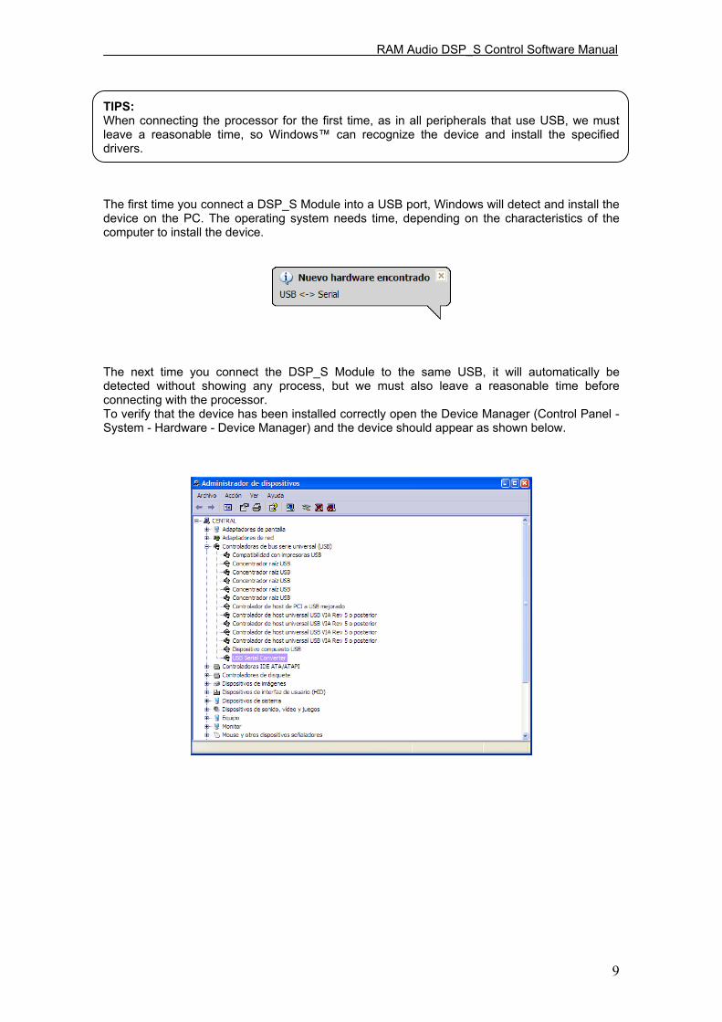
TIPS: When connecting the processor for the first time, as in all peripherals that use USB, we must leave a reasonable time, so Windows can recognize the device and install the specified drivers. The first time you connect a DSP_S Module into a USB port, Windows will detect and install the device on the PC. The operating system needs time, depending on the characteristics of the computer to install the device. The next time you connect the DSP_S Module to the same USB, it will automatically be detected without showing any process, but we must also leave a reasonable time before connecting with the processor. To verify that the device has been installed correctly open the Device Manager (Control Panel - System - Hardware - Device Manager) and the device should appear as shown below.

RAM Audio DSP_S Control Software Manual
10
2.2. - Uninstall To uninstall DSP_S Control software you must proceed as you would do with any other software. From the Control Panel go to Add / Remove Software. Here select DSP44_S and press the Add / Remove button ... We recommend making a backup of all configuration files created (.d44, .d22 and .d24 format) to use them later. 2.3. - Launching DSP_S Control Software The installation program creates an entry in the list of programs from Windows Start menu under the name DSP44_S. To operate the program from the Start menu, select Programs, and search for the Folder named DSP44_S. Then click on the software icon. If you created a shortcut to the Windows desktop, just double-click on the icon:
The first thing that appears is the start-up screen which shows the process of loading the modules of the programme and the version.
After launching the application we are asked the type of connection with the processor, no matter the model it will always be the same.
There will be two options: - Not connected at all (Offline). - With the Processor on the USB port.
If you want to work with the processor connected to the computer, take the USB cable and connect one end to the corresponding port and the other into the DSP_S Module.
When selecting USB connection, it establishes communication with the processor and it will display the communication screen.
If the communication is established correctly, the screen will disappear quickly giving way to the main screen of the program.
If there is a problem in communication you will see a window showing that there is a communication error, please verify that the USB port is correct.

RAM Audio DSP_S Control Software Manual
11
2.4. - FIRMWARE Upgrade The firmware update is done automatically. The software contains the latest version of firmware. When establishing the connection, it checks the version of the processor firmware. If it is a lower version, it will be updated following these steps: If you choose no, no action will be made, but the processor will keep the same firmware Version, and you will need a previous Software version to run it. If instead, you say you want to update it, there is a window of information with important indications that you must pay attention to. Press Send to start the process. First, an update on the DSP will be made, once the Update is done, firmware update will start. As soon as the processor starts having a new FIRMWARE, the screen will show you the following message:
Updating FIRMWARE Do not touch anything
This indicates that the processor is being updated, and it is recommended that you DONT TOUCH anything to prevent mistakes in this delicate moment. 2 INSTALLATION First Step will be deleting the Flash memory to make it ready to write the new data.

RAM Audio DSP_S Control Software Manual
12
Once it is empty, write new Data will start. If the process is executed correctly, the next screen will appear: Then you have to switch Off the S amplifier and then switch On.

RAM Audio DSP_S Control Software Manual
13
3. EDITING WITH DSP_S Control 3.1. - Main Screen Upon entering in the DSP_S Control software, the main screen appears, which represents exactly the internal structure of processing. Here we can see the path that runs the audio signal from the inputs to the outputs in a very easy visual way, showing the different blocks and order of the signal flow. From this main screen you can directly access all settings. The elements that compose it are: Memory number DSP_S Model Entry labels Output labels Signal route buttons
Configuration buttons Additional Info Memory name Final response Zone access Real Time description Indicator Status bar If we launch the software in Offline mode, without connecting to the processor, the buttons on the Tools menu-related to communications with the processor will remain inactive, appearing in grey, while on the Status bar it will say: Offline. We can select the DSP_S model (from the scroll down menu) that we want to configure. With the configuration buttons, we can access each one of the configuration screens, such as equalization, crossovers, gain, delays or dynamics. Using the signal route button we can select from where you want the signal to be taken. There are six options: 1, 2, 1+2, 3, 4, or 3+4 for DSP44. In the Tools menu we have access to options to read, create or save configurations, as well as the information icon, and all related to the communication with the processor: establish the connection, read and store in memory configurations, security options and update the DSP firmware. The Status bar will show you the status of the connection with the processor:
USB, Offline. With the Additional Info button we can give a name to the configuration created and add more data such as name of the project, engineer or technician responsible and comments. With the Copy Button we can copy the selectable parameters from one output to another. And through the entry and output labels we will be able to name them, which will serve as a reference in future windows.

RAM Audio DSP_S Control Software Manual
14
Depending on the status of the connection, Real Time Button will look like: Offline Online Clicking on the red button we can choose between working in real time or not. We recommend that you make the whole configuration offline, save it into a memory, and then work on real time only to do the "final touch". This option will be unavailable if we are working in offline mode or the processor is unplugged. In that case, you will get the following error message: Output configuration buttons.
ROUTE: Clicking on this Icon you will be able to select from which of the inputs that channel will take the signal. Options are 1, 2, 1+2, 3, 4 and 3+4 for DSP44.
XOVER (Crossover). Access to the configuration window of the Crossovers where we can set up filters of each Output. It has Linkwitz-Riley, Bessel and Butterworth filters of 2nd, 4th, 6th and 8th order. It is also possible to leave them in Bypass and have a full range of output.
PEQS (Equalization). We enter in the parameters of equalization of each Output. We have per output 9 fully configurable filters or selectively Bypass, Parametric: (Q constant or adaptive), Shelving of low and high frequencies of 6dB/oct and 12dB/oct (with or without Q), LowPass / HiPass (with and without Q ), Bandpass, Stop Band and AllPass first and second order. With them you can equalize each one of the outputs separately or link between them.
GAIN: Pressing the "E" button, you will access the Main Gains window. From here you will be able to adjust the Gain on each output. You can also Mute, invert the Polarity or activate the "Solo" mode. You are also able to do all this from the Main Window.

RAM Audio DSP_S Control Software Manual
15
DELAY: Allows you to set delays for each Output. For each main output you have 20.81 milliseconds to be used in the alignment of the boxes of a system or inside a box itself and correct the gap by not being in the same vertical plane.
DYNAMICS: It will let you adjust the parameters on the RMS Limiter and/or Peak Limiter. From here, you can apply protection to your speakers. In order to access the parameters window you will have to press the corresponding button; RMS Dynamics or PEAK Limiter.
FINAL FREQUENCY RESPONSE: In this screen you will be able to see the final frequency response after all the settings have been applied. You will see the effect of applying different filters, gains and also see the Phase obtained. You also have the capability to import Frequency response from measure softwares such as CLIO, MMLS, Smaart Live etc, to apply correction with the filters of the processor till you obtain the desired best electroacoustic response.
Additional Info. It gives access to General Info window, where you can input the name of the system which you are working on, Sound Engineer name, Project or venue name, or comments.
Copy. This utility lets you choose between parameters of each output to copy them between the channels that you want, in case you want the same parameters in two or more channels.
3.2. - Editing in Offline or Real Time mode Once you have some general information of the use of the main windows, we can start working with the software. We can work with it in two options: in Offline Mode and in Real Time Mode. By default, software starts in Offline mode, which is the safest way to work on complete setups. If you have previously connected the processor, then you'll be able to work in Real Time, pressing the Real Time button which appears in every configuration window. You will easily see when you are working in Real time because the button will be bright red. Every parameter of the DSP_S Module can be configured in Real Time from the DSP_S Control software. When you want to make a new configuration, we recommended that you make it in Offline mode, to avoid human error, such as the move (by mistake) of the mouse wheel being this one on top of a window which chooses the type of filter and change a High Pass for a Low Pass, whose output goes to a HF driver, with the possibility of damaging your equipment.
RAM Audio DSP_S Control Software Manual
16
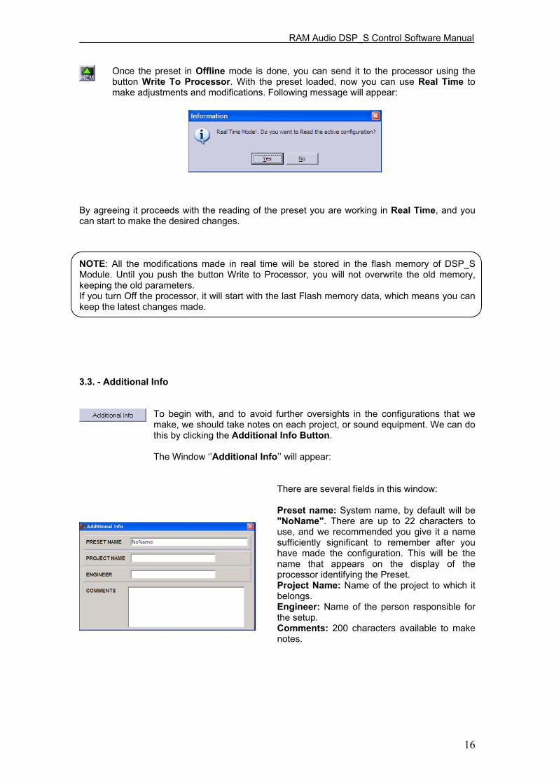
Once the preset in Offline mode is done, you can send it to the processor using the button Write To Processor. With the preset loaded, now you can use Real Time to make adjustments and modifications. Following message will appear:
By agreeing it proceeds with the reading of the preset you are working in Real Time, and you can start to make the desired changes. NOTE: All the modifications made in real time will be stored in the flash memory of DSP_S Module. Until you push the button Write to Processor, you will not overwrite the old memory, keeping the old parameters. If you turn Off the processor, it will start with the last Flash memory data, which means you can keep the latest changes made. 3.3. - Additional Info
To begin with, and to avoid further oversights in the configurations that we make, we should take notes on each project, or sound equipment. We can do this by clicking the Additional Info Button.
The Window Additional Info will appear:
There are several fields in this window:
Preset name: System name, by default will be "NoName". There are up to 22 characters to use, and we recommended you give it a name sufficiently significant to remember after you have made the configuration. This will be the name that appears on the display of the processor identifying the Preset. Project Name: Name of the project to which it belongs. Engineer: Name of the person responsible for the setup. Comments: 200 characters available to make notes.

RAM Audio DSP_S Control Software Manual
17
3.4. - Input and Output Labels From the Main Screen you can identify the Inputs and Outputs that you are going to use. You can do this by labels, the image shows:
To write a name on the label, click once over it, a cursor will appear and then you can enter with the keyboard the characters you want (up to 6 characters). You can move from one to another directly by pressing the tab key.
Through these names you can identify each Output. These names will appear later in other windows, to make the software more intuitive and comfortable, so you know what you are changing on which specific Output and you will not have to revise which channel belongs to which output. The same label will appear on the processor display.
For example, in one Stereo 2 way configuration, you will write Left on Input A, Right on Input B, and in Outputs you can write HIGH L, HIGH R, LOW L, LOW R in order from Output 1 to 4.
Once you assign a name in each box, the corresponding name will change, being able to identify clearly every Input and/or Output.
3.5. - Signal Routing Already at Output section, the first button you will find is the ROUTE button. With Route buttons, you will be able to select from which input the signal will be taken through the channel Output. In order to do that, press the button till you find the desired Input signal, Steps are 1, 2, 1+2 (mono), 3, 4, 3+4 (mono). You will see the number of the input drawn at the Icon. 3 - EDITING

RAM Audio DSP_S Control Software Manual
18
3.6. - Cross Over configuration. After routing, you will find X-Over configuration section: Press the XOVER Icon on the desired Output, screen CrossOver Configuration will appear:
Show Magnitude or Phase vs. Frequency
Response of filters Cut frequency Type of filter Hide or Show other outputs Order Reference labels Select to Edit 3 - EDITING The two columns represent the low cut (High Pass Filter) and higher cut (Low Pass Filter) in which you can configure crossover frequencies, the type of filter used for CrossOver and order of each filter to adjust the slope. To edit the values simply go to the box and put the desired values with the keyboard or modify them with the mouse click up or down. The change will take effect by pressing press Enter or leaving the box. Select the channel on the "Modify" buttons. Beside them you will have the labels with the name of each output. As in PEQ, the display will show at the bottom the value of frequency and magnitude or Phase filter crossover in the current mouse position. We have the following filters and slopes:
· Bypass No filter. · Butterworth 12dB, 24dB, 36dB and 48dB / Octave · Linkwitz-Riley 12dB, 24dB, 36dB and 48dB / Octave · Bessel 12dB, 24dB, 36dB and 48dB / Octave
To choose the type of filter, High Pass or Low Pass of each route, you will select the desired option in the drop-down menu, changing type of filter and Order (being the slope of the filter in dB / Oct = 6 x order).

RAM Audio DSP_S Control Software Manual
19
We have 8 filters of 2nd order by CrossOver. Four for the lower cut and four for high cut. You can go up to 8th Order by cut. In case you do not want any cut on the signal, simply leave the type of filter in Bypass, in one or both filters. The cut-off frequencies of the filters are set at points of -3 dB for Bessel and Butterworth filters, and -6 dB for Linkwitz-Riley. When you put the same type of filter in a Low Cut channel and a High Cut on another channel with the same frequency in both, to get a correct amount of signal summon, it will require reversing the phase towards lower frequencies when using:
· Butterworth of 2nd order at same frequency cut in both ways. · Linkwitz-Riley of 2nd order at same frequency cut in both ways. · Bessel of 2nd order at same frequency cut in both ways. · Bessel of 2nd order in the Low Cut and 4th order on High Cut (or vice versa) at the same frequency cut.
The ideal total electricity response will be in case of 4th+4th LinkWitz-Riley or 2nd+2nd with phase inverted on one of the channels. In other cases, you will be creating an enhancement of about 3dB for Butterworth and a ripple of approximately ± 2dB on Bessel. However, you get a better response in the crossing area of both ways, and that is because you solved phase problems, typical in these cases. Even so, we must never forget the final response of the transducer itself connected to this configuration, because it will influence the final phase response. It is possible to obtain almost a flat response on the crossover area with a little ripple using the same type of filter and order but by changing the frequency cuts, going down on Low pass, and up in High pass.
For example, for an almost flat response on the crossover area with Bessel filters of 4th order in 1000 Hz, you must go with the LP to 875 Hz, and to 1250 Hz on the HP. You can check that in the Final Frequency Response window, enabling the Influence of the crossover and activating on "SHOW" only the 2 outputs that you are using, enabling the ADD response also, as you can see on the Image.
When you can adjust both independently, upper and lower crossover filters, you will have the freedom to create asymmetrical crossovers with different frequencies, slopes and types of filters. Necessary in many real cases, where the use of these asymmetric crossovers, electrically speaking, provides electroacoustic perfect crossover area.
3.7. - PEQS - Output Parametric Equalization After the Crossover section we find the PEQS (Parametric Equalizer) for outputs. By pressing either of these icons the Equalizer window will appear from where you can adjust these parameters:

RAM Audio DSP_S Control Software Manual
20
Frequency Magnitude or Response Phase view Selector
Save EQ file data Open EQ file Data Linking channels Filter in Use Channel Selector Type of filter Show graphics Filter Parameters
Reset every filter (flat) If you have an equalization curve file stored in the computer and you want to import it into your
project, you must press the icon:
If you want to save to current equalization curve file for later use or import it to other setting, you
must press the icon:
The frequency response is shown at the top. You will see the curves of the equalizer that is active in Show, each with the same colour as their respective indicator. You have 9 fully configurable filters on each Output. 3 - EDITING To modify or change a parameter you have to:
- Select in MODIFY the equalization that you want to change, and make sure that the corresponding channels are activated on the "SHOW" section.
- You will see a square mark on the curve equalizer with a number, indicating which of the nine filters is the one that you are editing. This issue will also appear at Filter into the box in the parameters of the filters. Modifying this box (Filter Number) you can go between the filters available, updating the rest of the parameters to the values of each filter. By default, all filters are in Bypass with a gain of 0 dB and an initial frequency of 1000 Hz.

RAM Audio DSP_S Control Software Manual
21
- Once you select the filter to modify, you should select what type of filter you want. Opening the Filter Type drop-down list, you will have the following options:
· Bypass: No filter. · Parametric: Parametric filter that allows you to adjust the gain or attenuation, the frequency of performance and quality Q factor. The value of Q is defined as the ratio between the width and centre frequency of the bandwidth between middle gain points. It can be adaptable Q or constant Q. · Shelv Low 6dB: Shelving filter or hood to mitigate or enhance low frequencies with a slope of 6 dB per octave. · Shelv High 6dB: Shelving filter or hood to mitigate or enhance high frequencies with a slope of 6 dB per octave. · Shelv Low 12dB: Shelving filter or hood to mitigate or enhance low frequencies with a slope of 12 dB per octave. · Shelv High 12dB: Shelving filter or hood to mitigate or enhance high frequencies with a slope of 12 dB per octave. (We also have filters with Shelving slope of 12 dB per octave with configurable Q option.) · LowPass Buttw: Low Pass filter Butterwoth type, of 2nd order. · HiPass Buttw: High Pass filter Butterwoth type, of 2nd order. · LowPass Q: Low Pass filter of 2nd order with Resonance control. · HiPass Q: High Pass filter of 2nd order with Resonance control. · BandPass: Band Pass filter with variable Frequency, Q and gain parameters. · StopBand: Stop band Filter with variable frequency and Q. · Allpass 1: All pass filter of 1st order, it moves the phase 90º (degrees) on the selected frequency. · Allpass 2: All pass filter of 2nd order, it moves the phase 180º (degrees) on the selected frequency, with phase change depending on the Q.
- Depending on the type of filter that you select, modifiable parameters will be activated, those will be: Frequency, Q (quality factor) and Gain. All the parameters are editable from the keyboard. The Frequency, Q and Gain can be directly changed by entering data on the keyboard and pressing enter. Q and Gain can also be edited through Arrow Up, Arrow Down.
- You can also change values of Frequency and Gain using the mouse. To do that, put
the mouse closer to the mark filter in the graphic until the icon change to:
Click and hold the mouse button in order to move the filter to where you want.
- If you need more filters, simply move to another one in Filter Number. Same thing to change between channels, use Modify screen.
- It is also possible to see the phase response of an equalization selecting from Mag to Phase.
- Below the frequency response, you will always have information that indicates the frequency and magnitude in dB or phase in degrees of the current equalization.

RAM Audio DSP_S Control Software Manual
22
The characteristics of the Parametric and Shelving filters available are shown in these graphics: Parametric, adaptable Q. G = 12, 9,6,3,0,-3,-6,-9,-12 f = 1000 Q = 1 Parametric, constant Q. G=12, 9,6,3,0,-3,-6,-9,-12 f=1000 Q=1 Parametric, adaptable Q. Q = 0.3,0.5,1.0,1.5,2.5,5,10,20 f = 1000 G = 12 Parametric, constant Q. Q = 0.3,0.5,1.0,1.5,2.5,5,10,20 f = 1000 G = 12 Shelving 6dB/oct f = 100,10000 G = 12, 6, -6, -12 Shelving 12dB/oct f = 100,10000 G = 12, 6, -6, -12

RAM Audio DSP_S Control Software Manual
23
BandPass Q = 0.9,1.5,2.5,5,10,15,20 f = 1000 G = 12 StopBand Q = 0.9,1.5,2.5,5,10,15,20 f = 1000 LowPass Q Q = 0.3,0.5,0.8,1.5,2.5,5,10 f = 1000 HighPass Q Q = 0.3,0.5,0.8,1.5,2.5,5,10 f = 1000

RAM Audio DSP_S Control Software Manual
24
3.8. - Output Gain From the Main screen, or from the Gain Levels window, you can adjust the levels of each output, also you can apply Mute, invert the polarity (Phase) or activate the Solo mode. By clicking on the "Link" boxes you can give the same parameters to other channels.
Output Gain area. By pressing the «E» button you will see this window:
By default all Gains appear at 0 dB. We have +6 dB of gain and -30 dB of attenuation, in increments of 0.1 dB. You can use the sliders, or if you w ant a precise control you must use the keyboard arrows up and down, t o go from 0.1 dB of 0.1 dB..
You can also Mute outputs by clicking on the red buttons (Mute), reversing the polarity (phase) out if you activate the yellow buttons (ø) and if you press the green button (Solo), it will mute every output except the one pressed.
If you activate some mute, the main display will show a red cross and will turn off the labels for this output:
Without Mute
With Mute
You can adjust Output Gains for example: in order to get the right signal to each of the connected amplifiers, according to their own input sensitivity. And/or to compensate electrically the different ways depending of the sensibility of the transducers in a multi way system, knowing that most of the times High and Mid frequencies needs an acoustical adjustment. The Mute will be activated in the inputs or outputs not used, to avoid possible confusion. The polarity inversion will be very useful to quickly solve phase problems. If you have some inverted cable it will help to avoid a "rewire". It will also be necessary to use in case of having to supplement two 2nd Order Crossovers, and then obtain a «in phase» intersection.

RAM Audio DSP_S Control Software Manual
25
Another useful situation will be in case the physical location of Sub bass cabinets are not in the same vertical plane as the rest of the P.A. You will probably fix that by reversing the polarity applying a 180º of phase inversion, but, we recommend to use Delays to set up the adjustments precisely. Finally you will always have a reference of what any changes made with each output, thanks to the labels attached on the main screen. 3.9. - Output Delay This is the next button you will see: This button will open the DELAY window; the screen will look like this: In this window, you can configure the final delay to each way. To do this you have sliders that allow you to adjust the various delays in the outputs on steps of minimum samples. By modifying any of them, the value of the delay in centimetres and in milliseconds will be displayed below. If you are fine-tuning delay setup, you can enter to the indicators and increase or decrease with the keyboard up and down arrows. You also have the option of Temperature change, through which you can introduce the temperature (in Celsius or Fahrenheit) making the calculation of the speed of sound as accurate as possible. The calculation of the speed of sound (Vs) depending on the temperature is obtained with the following formula:
Vs = 20.06 x √ (273+ºC) m/s being ºC the temperature in Celsius degrees. In this formula, and taking an average temperature of 20 ºC (68 degrees F) the following useful relationships are obtained:

RAM Audio DSP_S Control Software Manual
26
Delay in miliseconds = distance in meters x 2,9123
Delay in miliseconds = distance in feet x 0,8876
Distance in meters = Delay in miliseconds x 0,3434
Distance in feet = Delay in milieseconds x 1.1267
In each output we have a delay of 20.81 miliseconds (7.21 meters to 25 ºC). You can use these delays for:
- Correct the vertical position of the boxes on a multi-way system that is not in the same vertical plane, or that part of the boxes (for example, HIGH-MIDs) are flown, and the rest (LOWs) on the floor, having different distances to the listener. In any case you will have the correct path difference calculated, and add the corresponding delays in each of the ways in order to make them arrive at the same time to the audience.
- Make fine adjustments between transducers inside a cabinet. Normally the physical placement of each transducer in one box does not match exactly in its vertical plane (for example a 12-inch speaker and a 2-inch driver), and also the order of filters used and the phase response of each transducer rarely coincide. In this case you can correct this effect with an accuracy of 0.7 centimetres, to obtain a completely in phase output and have a coherent wave front.
For that we include the possibility of introducing the distances between elements on each output referring to a vertical plane. As shown in the following picture:

RAM Audio DSP_S Control Software Manual
27
With these distances we can add the necessary delay to each channel, and visualize as the elements are lining up. When all appear in the same line we will be ensuring that all distances are compensated and then the system will provide a "phased" wavefront. As shown below: We also have the AUTO-ALIGN button, which will internally calculate times, and automatically adjust all the delays required to leave the system in phase. It is recommended the importation of each transducer curve (which should be taken under the same conditions) and go to the Final Response screen to see the effect on final electroacoustic response, looking at the same time the total response of the sum of the channels, where we will study the effects of delay when the whole system is not compensated. 3.10. - Dynamics configuration The last section that we find on the Main window is the audio Dynamics, which consists of a block of RMS Dynamics and followed for another block of Peak limiter. Once the signal reaches this point there will be some parameters already applied, Route selection, Gain, Crossover, Equalization and delay. All that remains is a dynamic control (compressor - limiter). Each output provides a sophisticated RMS compressor-limiter followed by a Peak limiter. The limiters and compressors are C.R.I. type (Continuous Ratio Increment) with a low distortion. First we use a RMS Detector to get high quality compression. The system will reach the maximum power in a gradual delivered way, so then the sound will be perfectly clear and crisp at all times, avoiding the typical problems of normal limiting. First you have to introduce the gain amplifier, the impedance of the speakers you are working with and using the RMS Power slider you fix the power you want. Then we will have the Peak limiter with which you can control the maximum in mechanical displacement of the loudspeakers. To adjust limiters, you introduce gain amplifier and adjust the Peak Voltage with the corresponding slider. In this way we will have a final control of the dynamics and you can limit the power delivered at each output precisely. To access this part, press over the icons of RMS (Dynamics RMS) or PEAK (peak limiter):
RAM Audio DSP_S Control Software Manual
28
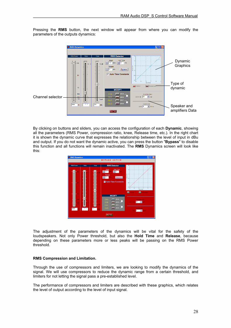
Pressing the RMS button, the next window will appear from where you can modify the parameters of the outputs dynamics:
Dynamic Graphics
Type of dynamic
Channel selector
Speaker and amplifiers Data
By clicking on buttons and sliders, you can access the configuration of each Dynamic, showing all the parameters (RMS Power, compression ratio, knee, Release time, etc.). In the right chart it is shown the dynamic curve that expresses the relationship between the level of input in dBu and output. If you do not want the dynamic active, you can press the button "Bypass" to disable this function and all functions will remain inactivated. The RMS Dynamics screen will look like this: The adjustment of the parameters of the dynamics will be vital for the safety of the loudspeakers. Not only Power threshold, but also the Hold Time and Release, because depending on these parameters more or less peaks will be passing on the RMS Power threshold. RMS Compression and Limitation. Through the use of compressors and limiters, we are looking to modify the dynamics of the signal. We will use compressors to reduce the dynamic range from a certain threshold, and limiters for not letting the signal pass a pre-established level. The performance of compressors and limiters are described with these graphics, which relates the level of output according to the level of input signal.

RAM Audio DSP_S Control Software Manual
29
These curves are presented as follows: dB dB In the Compressor, the Output signal follows the Input signal if you are below the threshold. Once it exceeds, the output is mitigated depending on the chosen Ratio. In the next graphic there is a 1:2 ratio, which means that once the signal exceeds the threshold for every 2 dB increase in the input we will have 1 dB increase in the output. The limiter works like a compressor with 1:∞ (infinite) Ratio, not leaving to the output level exceeds the threshold. The algorithm used in the dynamic is quite sophisticated, it uses a RMS detector with variable attack and release times, depending on the response speed (or time constant) introduced into the Attack and the Release box (both speeds introduced in dB per second). The RMS detectors have a certain time constant that determines how fast it can respond to transient signals, this will be introduced through the Attack box. If the detector response is very fast, the envelope will produce a harmonic distortion by multiplying the signal detector. The DSP_S Modules use a modified RMS algorithm to improve this relation between speed and distortion. To better understand how the dynamics work, observe the following example, with the threshold values -6 dB, 120 dB Attack / s, 40 ms Hold and Release of 7 dB / s. (Shown in green; signal without limit and a red signal after the RMS limiter)

RAM Audio DSP_S Control Software Manual
30
When the input signal exceeds the RMS Power threshold compression/limiting fixed, dynamics start working, reducing the signal to this threshold. The amount of time this transition lasts is the Attack time. When the input signal fails to exceed the RMS Power threshold, the reduction factor applied on the input becomes minor, until the compressor / limiter fails to act. This time is called RELEASE. If the input signal starts to overcome the RMS Power threshold again, and the time of Release has not arrived, the dynamic start again, getting smaller transient signal and an Output that will be within the limiting set. Fast speed Release (shorter time-release) will allow you to regain the level of original signal too fast, attenuating levels before the arrival of more signal. This effect introduces much «pumping» and even distortion, in extreme cases getting a broken sound. This effect can also occur for high values in the Attack time. The third time we can configure is the HOLD. This would be the time that elapses between when we are below the RMS Power threshold until the Release enters. The adjustment of these parameters is very important and critical for the final sound quality. These speeds depend on the frequency range of the input signal. For Low frequencies speeds will be slower and times longer, while for high frequencies it will be faster. If the signal to compress or limit is a full range, we have to think that almost all the energy of the signal is in the Low range frequencies, so it will take slow speeds (around 120 dB / sec in attack and 7 dB / sec in release). In case you are not experienced on it, use the Auto Time Constants key and Attack, Release and Hold Time will be fixed at their better value, depending on the x-over frequencies in each way. It is really very advisable using this utility when you are not sure about precise values of these constants, in this way you will avoid to have bad fixed limiters, preventing damages in the loudspeakers or unpleasant noises when limiters are acting. C.R.I. Compression One problem with traditional compressors and limiters is that the entrance to the compressor or limiter is very punctual (happens exactly at the time the signal passes the threshold level) and can be heard clearly in the sound when it is playing, affecting the natural dynamics of the music. To solve this problem we used C.R.I. (Continuous Ratio Increment) dynamic curves, at which the threshold shifts from a defined angle to a continuous curve that links perfectly the linear area of compressors and limiters with 1:1 ratio with the compression or limitation configurable decibels range. In these cases it continuously varies the elbow or knee of the limitation or compressors in the range of dB we want. This effect of compression and progressive limitation applied to multi-way systems leaves a much more transparent dynamic control, because the headroom or signal margin available is not dead when the limiters enter, almost disappearing the fading effect of choking typical traditional limiters.

RAM Audio DSP_S Control Software Manual
31
The C.R.I. curves employed in the DSP_S Modules are like the ones shown below: The graphic of the C.R.I. limiter shows a "normal" limiter of +4 dB compared with the C.R.I. limiters with +4 dB with a knee ± 2, 4, 6 and 8 decibels of action. There you can see that the dynamic control is becoming more progressive and we still have headroom even when the Limiter acts. In the case of C.R.I. compressor, the threshold is set at +4 dB and the ratio is 1:3, 3 decibels increase at the input provide 1 decibel in the output. It also appreciates the same gradually control effect, noting a much smaller initial attenuation of the input signal. The main advantage of using C.R.I. limiters against others is that their job carries intrinsically a compressor that evolves to a limiter depending on the input signal level, saving the need to include a compressor before it to reduce the dynamics. The C.R.I. limiters act like a compressor that evolves from a 1:1 ratio to 1: ∞ (infinite) dB range that we want with the Knee. The result is a more progressive and transparent way to maintain headroom even when it has already begun to act. The same occurs in the C.R.I. compressor where changing the ratio of 1:1 to 1:n where n is the new ratio selected. Compressor / Limiter Parameters

RAM Audio DSP_S Control Software Manual
32
First select want you want to use: compressor or limiter. Remember that the use of C.R.I. Compressor or Limiter carries a continuous compressor ending in a limitation. If Limiter is selected, the potentiometer on the left will appear the RMS Power, that will indicate the value of limitation, and the Ratio potentiometer will be turned off, as being a limiter it will be 1: ∞ (infinite). If we select Compressor, Ratio will become active. By varying the potentiometers you will modify the values of (taking from left to right) RMS Power: Level output; Ratio: compressor Relation; Knee: control of C.R.I. indicating the margin of decibels in which it operates. In all cases, the present value is shown below each potentiometer. By varying the Knee, we can move from a Normal limiter or compressor with Knee = 0dB to a C.R.I. with 10 decibels of acting range. Speaker and Amplifier parameters On the Dynamics screen, we can select the amplifier gain and the Impedance of the acoustic box. In this way, you can adjust the limit depending on the amplifiers gain you are using and impedance of the speakers used in the outputs of the processor: - Box Impedance: Impedance of the speaker or cabinet that you have plugged into that output. You have 2, 2.67, 4, 8 and 16 Ohms. - Amplifier Gain (linear): Here you have to introduce the value of the linear Gain selected in the amplifier. Once you have completed the configuration of RMS Dynamics, you find the PEAK button within the same section. This button gives us access to the configuration screen of Peak Limiter. With the Peak Limiter you can adjust and control the maximum mechanical displacement of the speakers of the system. To make the limiters adjustment we will use the values of the amplifier gain used and then we will adjust with the slider, the Peak Voltage.

RAM Audio DSP_S Control Software Manual
33
Peak Voltage Knee adjustment Peak timing Bypass button Designed
Dynamics curve Channel selector Amplifier parameters As in the screen of RMS Dynamics, if we do not want the Peak limiter to work, we can press the Bypass button to disable this action. Then the Peak Limiter screen will look like this: By default, when you connect a S amplifier with DSP module to the software, both limiters, RMS and Peak, are Bypassed; so if you want to configure the limiters you have to click Bypass button in order to introduce the parameters to fix the limiters.

RAM Audio DSP_S Control Software Manual
34
To better understand how Peak limiter works, observe the following example, with the threshold values on -6 dB, 40 ms of Hold and Release of 7 dB/s. (Shown in green signal without limit and a red signal after the peak limiter) When the input signal exceeds the threshold limit set (-6dB in this example), dynamics start working by reducing the signal to the threshold. The difference with the RMS limiter (see page. 29) is that the Peak limiter has no time attacking, since it is instantaneous and does not let any transitional signal above the threshold we have set. The Hold and Release time follows the same acting as RMS limiter. 3.11. - Final Frequency Response In the Main screen you will find this button: By pressing that button the Final Frequency Response will appear, where you can see in the same screen the cumulative effect of all process blocks such as the final response, PEQs (EQ), CrossOver (Xover), Gain and even the effect of Delays and the own electroacoustic response, if we import measures from external software by clicking in Import Data. The elements that make up the screen are:
Magnitude or Phase vs
Frequency Response Show/Hide channels Show/Hide Process Magnitude or Phase selector
Import Data Add/Summon from measures response

RAM Audio DSP_S Control Software Manual
35
In the boxes on the left we can activate or deactivate the influence of each one of the process blocks to the final response: Output equalization PEQ, Xover, Gains, Delay, and even the transducer own Loudspeakers response data (if it has been introduced in Import Data). It can also select Outputs that want to contribute in the simulation of the total Electroacoustic response (black curve). So, we can see the TOTAL input-output electrical response, or electroacoustical response if we introduce the measures of external Measurement software. We also have the SHOW section; there we can activate the curves that we want to visualize. By activating ADD, it will be displayed on the screen (in black) the total frequency response, taking into account the magnitude and the phase of all outputs that we have selected in this section. Remember that when you select any output, it will always be shown if it is not muted, then it will not contribute to the final frequency response. If we activate the option SPEAKERS DATA with speakers measures imported, we can see the electroacoustical response of the outputs and observe how these crossings areas are, and see also how the delays affects the frequency response adding a route against another. It is also easy to see the effect that changing polarity on outputs over the phase response around the crossing area, activating or not the button on the Gain screen. Import Data One of the most interesting characteristics that clearly differentiate the DSP_S Control Software against other products is the ability to work with real measures of cabinets or speakers. The sound Technician or Engineer can include this information at the end of the process chain and observe the electroacoustic response directly on screen, and even equalize it, until you get the final desired Response, either flat, loudness or as desired. To introduce these measures it is necessary to obtain measurements exported in ASCII format of one of the following standard measurement systems: - CLIO
- SMAART LIVE
- LINEAR X - LMS
- AUDIO PRECISION
- DAAS 32
- MLSSA
- Acoustilyzer FFT y 1/3 oct SPL
- WINAIR
- CALSOD
- SPECTRALAB
By pressing the button Import Data, in the Final Frequency Response window the next screen will appear that will allow us to introduce the ASCII files with the measurements of the transducer that you made.
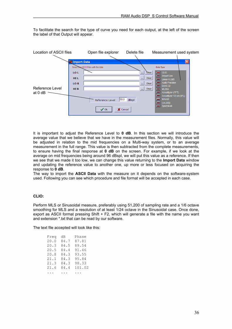
RAM Audio DSP_S Control Software Manual
36
To facilitate the search for the type of curve you need for each output, at the left of the screen the label of that Output will appear. Location of ASCII files Open file explorer Delete file Measurement used system Reference Level at 0 dB It is important to adjust the Reference Level to 0 dB. In this section we will introduce the average value that we believe that we have in the measurement files. Normally, this value will be adjusted in relation to the mid frequencies on a Multi-way system, or to an average measurement in the full range. This value is then subtracted from the complete measurements, to ensure having the final response at 0 dB on the screen. For example, if we look at the average on mid frequencies being around 96 dBspl, we will put this value as a reference. If then we see that we made it too low, we can change this value returning to the Import Data window and updating the reference value to another one, up more or less focused on acquiring the response to 0 dB. The way to import the ASCII Data with the measure on it depends on the software-system used. Following you can see which procedure and file format will be accepted in each case. CLIO: Perform MLS or Sinusoidal measure, preferably using 51,200 of sampling rate and a 1/6 octave smoothing for MLS and a resolution of at least 1/24 octave in the Sinusoidal case. Once done, export as ASCII format pressing Shift + F2, which will generate a file with the name you want and extension *.txt that can be read by our software. The text file accepted will look like this:
Freq dB Phase 20.0 84.7 87.81 20.3 84.5 89.54 20.5 84.4 91.46 20.8 84.3 93.55 21.1 84.3 95.84 21.3 84.3 98.33 21.6 84.4 101.02 ... ... ...

RAM Audio DSP_S Control Software Manual
37
SMART LIVE: To export a text file, go to File, and choose ASCII Save and then select which of the curves stored you want to export (A, B, C, D or E). The format accepted will be the following one.
; SIA SmaartLive Trace Output ; This File Created On Thursday October 16, 2008, At 10:02:50 ; ; Comment: ; ; ; ; --------------- Reference Trace C --------------- ; ; Comment: "No Comment" ; Sample Rate: 48000 ; FFT: FPPO ; Frequency Resolution: 24 points per octave ; Data Window: Hanning ; Y +/-: 0.0 ; 64 average(s) ; ; ; Frequency (Hz) Magnitude (dB) Phase (degrees) 11.7 *** *** 13.2 -44.42 -141.68 14.6 -45.07 -56.92 16.1 -44.46 1.39 17.6 -43.83 11.76
LINEAR X - LMS: In Linear X - LMS to get the ASCII file you have to measure, export the transfer function in magnitude and phase and give the name to the file which will be a *.txt format, and this must be equal to that shown below to be accepted by the software.
* LMS(TM) 4.5.0.352 Jul/01/2007 * (C)copyright 1993-2000 by LinearX Systems Inc * Jan 14, 2008 Mon 09:45 am * Library=Remeasure Production Cabinet Components.lib * Curve=Blackbird Prodn Cab HIGHS 4w4m, GP, HF_Vert 90' WI * Info1= * Info2= * Info3= * Info4=Data Measured: Jan 31, 2007 Mon 4:24 pm * DataPoints= 552 * DataUnits= Hz dBSPL Deg +1.000000E+001, -2.620938E+001, -4.523100E+000 +1.015170E+001, -2.568829E+001, -4.600700E+000 +1.030560E+001, -2.516673E+001, -4.679500E+000 +1.046190E+001, -2.464575E+001, -4.759400E+000 +1.062060E+001, -2.412489E+001, -4.840500E+000 ... ... ...

RAM Audio DSP_S Control Software Manual
38
AUDIO PRECISION: To import measure curves from AUDIO PRECISION ( *.ADX file extension) the DSP_S Control Software will ask for Frequency vs Magnitude file with the following format:
C:\Apwin\S2\Frequency Response.at2, 05/13/08 16:34:22 Gen.Freq, Anlr.Bandpass, ,,,,,, Source 1, Data 1, ,,,,,, Hz, dBr A, ,,,,,, 20, 61.5748731269, ,,,,,, 21.1796875, 62.7706794483, ,,,,,, 22.4375, 64.0570482866, ,,,,,, ... ... ...
Then you will be asked for the next file which contains Frequency vs. Phase data as shown below:
C:\Apwin\S2\Phase.at2, 06/17/08 10:26:17 Gen.Freq, Anlr.Phase, ,,,,,, Source 1, Data 1, ,,,,,, Hz, deg, ,,,,,, 20, -1e+032, ,,,,,, 21.1796875, -1e+032, ,,,,,, 22.4375, -1e+032, ,,,,,, ... ... ...
MLSSA: In order to obtain the ASCII file of a frequency response on MLSSA after measure, go to Transfer Function Magnitude and apply some smooth to the graphic. Once the screen shows this, go to Transfer, Export, Bode, and choose the phase (normally Actual-phase). Select a resolution of 1/6 of octave and assign a name to the text file that will be created. It will looks like the following:
"Transfer Function Bode Plot - dB volts/volts (eq)" "Hz" "Mag (dB)" "deg" 18.42571, 8.800242, 1.53268 36.85141, 12.55392, -120.637 55.27712, 9.681987, -62.79101 73.70283, 11.5648, 123.8057 92.12853, 12.57369, 102.3705 ... ... ....
ACOUSTILYZER: We are able to import measurements of FFT data from Acoustilizer. Also with a 1/3 octave smoothing in SPL. We have to import the *.txt file, that will have frequency response, magnitude but no phase information. The file will look like this. FFT Measure SPL 1/3 Octave > file: A025_FFT f[Hz] Level[dBSPL] 20.00 48.0 > FFT 25.00 33.8 > range: 34 dB - 114 dB 31.50 38.6 > mic sensitivity: 20.00 mV/Pa : 16000.00 26.5
f[Hz] SPL[dB] 20000.00 25.8
187.50 81.8 375.00 76.1 17250.00 39.5 17437.50 38.6

RAM Audio DSP_S Control Software Manual
39
WINAIR : Select MLS as analysis signal, and once you have the measure ready, one or an average of, go to "Storage" and "save as", put a name and it will be saved a *.txt file. The format should look like this:
WinAIR saved file Samples per second 44100 Number of points 1024 Hz Amplitude Phase 21.533 210.38184 0.00 43.066 51.68376 1.40 86.133 42.01191 0.18 129.199 27.09770 -0.13 172.266 19.68722 1.40 ... ... ...
CALSOD / DAAS 32: To use measurements from DAAS 32 we need to export the Calsod files, they normally are *.spl extension files for DAAS 32. The file will contain Freq response, magnitude and phase data. The format will be like this:
CALSOD Frequency resp. NoName 0000 , 2 0.0 0.0 1.0 0
13.33 33.80 58.70 15.58 35.00 57.90 18.20 36.70 56.40 21.27 39.30 53.50
SPECTRALAB: From the screen called SPECTRUM click on Overlay options; you will be taken to the Overlay Management window from where you can click on Save Overlay (*.OVL). This file it will look like the following example:
;PH-N15 EQ 5.8594 -34.657658 8.7891 -27.767826 11.7188 -24.034397 14.6484 -19.426538 17.5781 -14.704682 ... ...

RAM Audio DSP_S Control Software Manual
40
General Considerations for taking Measurements. It is very important to take the measurements of the speakers correctly; so subsequent results are reliable and valid. The following list can be a useful guide to obtain good measurement data files.
1 - Take measurements of all the ways at the same distance (several meters) and with the microphone placed at the level that we consider as a central point of listening. Thus the magnitude and phase information of all measurements will be the same.
2 - The measurement equipment must be configured equally in all measures, i.e.: input or output signal gains, sensitivity, sampling rate, and so on should not vary from one measure to another.
3 - It is recommended to take measurements with smoothing (between 1/3 and 1/6 octave) in order to have graphics with less valleys and peaks. Also, remember that the functioning of the Human ear is similar to an analyzer between 1/3 and 1/5 octave or so.
4 - Try to take measurements in the same conditions that the equipment will have at work time. Like same amplifiers, gain levels and cabinets. Keep those settings knowing that any change will affect the performance.
5 - In the case of measuring with MLS (Maximum Length Sequence) and windowed the response time to avoid reflections on the measurement, take the same time window on all measurements, and eventually with the initial time common to all. In this case, we will have the same phase information in all measurements and the final electroacoustical sum will be correct.
6 - The measurements in mid-and high frequencies are almost always correct in the case of measuring with MLS avoiding reflections on the extent to windowing over time. But for low and mid-low frequencies, the inevitable problems of reflections and standing waves may distort the measurement in both magnitude and phase. In such cases we must always interpret the action, because if we want reliable measurements they should take place at anechoic chamber or in free field. These problems are most critical in closed rooms than outdoors.
7 - Store all files exported in ASCII in the same directory with clear and significant names in order to remember clearly what the measurement was.
8 - In case of using the DSP_S Modules as a final equalizer, it is possible to measure the entire system and equalize on it in the PEQs section in order to correct the overall response.

RAM Audio DSP_S Control Software Manual
41
In the next graphics, it's shown an adjustment example for the Mid and High ways in a real equipment using the transducers measures. First it's shown only the measure of the natural response of the speakers in his box and with their corresponding Amplifier. Only the Speaker Data option is active. Be seen as the high driver sensitivity is roughly 10dB higher and presents a small fall on 12Khz. Working on measures and according to them, high frequencies can be reduced 10 dB from the Gains screen. Mids are cut at 200 Hz below and 2kHz above with 4ºorder 24 dB/oct Linkwitz-Riley filters and Highs at 2000 Hz with 4º order 24 dB/oct Linkwitz-Riley. Subsequently, the equalization of each output is corrected from the PEQs whereas you still view Final Response to observe the changes. The electric processor response will be the shown in the figure: PEQ + Xover + Gains response. If now you Include/activate the speaker response you will see the total electroacoustic response exactly as it appears on the right screen. Finally, you will activate the ADD button. The two ways sum response is the one in black colour.

RAM Audio DSP_S Control Software Manual
42
4. - CONFIGURATION 4.1. - Tools Menu Once the parameters are in place for whatever configuration you need, it will be necessary to write on the processor memory what you saved on your computer hard disc, depending on the model DSP44 / DSP22 / DSP24, so these will be ready to work just like you wish. All options are accessible from the Tools menu buttons. These buttons are shown below. Leaving your mouse over any of these buttons and waiting a bit, you'll see a brief description or Hint about it in a box. Read the memory in use
Read a memory Write a memory Language
Connect Execute memory
Information Save configuration Security options Open configuration Upgrade DSP New configuration Locked DSP_S model
(if connected) It is possible that some of the buttons appear inactive. Depending on whether you work in Offline mode or connected to the processor, all the buttons related to communication assets will appear or not. - DSP_S model: When we are connected with any DSP_S processor, in the DSP_S model box will appear this model (DSP44, DSP22 or DSP24) and you will not be able to change it to another model, this box will remain locked. Only it is possible to change the model of the DSP_S processor when you are working Offline. Also down on the same screen is a status line: which informs us the type and status of the connection, it will say to whom we are connected and from where. If we are not connected to any DSP_S processor, it will appear Offline.
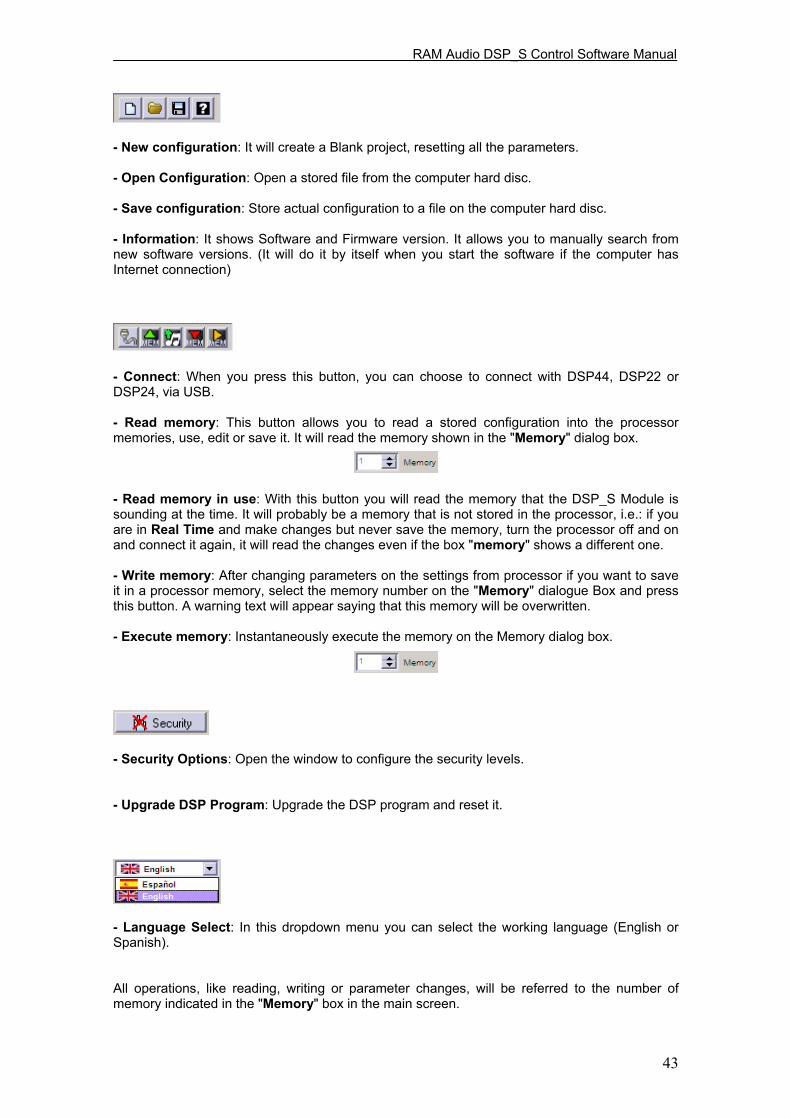
RAM Audio DSP_S Control Software Manual
43
- New configuration: It will create a Blank project, resetting all the parameters. - Open Configuration: Open a stored file from the computer hard disc. - Save configuration: Store actual configuration to a file on the computer hard disc. - Information: It shows Software and Firmware version. It allows you to manually search from new software versions. (It will do it by itself when you start the software if the computer has Internet connection) - Connect: When you press this button, you can choose to connect with DSP44, DSP22 or DSP24, via USB. - Read memory: This button allows you to read a stored configuration into the processor memories, use, edit or save it. It will read the memory shown in the "Memory" dialog box. - Read memory in use: With this button you will read the memory that the DSP_S Module is sounding at the time. It will probably be a memory that is not stored in the processor, i.e.: if you are in Real Time and make changes but never save the memory, turn the processor off and on and connect it again, it will read the changes even if the box "memory" shows a different one. - Write memory: After changing parameters on the settings from processor if you want to save it in a processor memory, select the memory number on the "Memory" dialogue Box and press this button. A warning text will appear saying that this memory will be overwritten. - Execute memory: Instantaneously execute the memory on the Memory dialog box. - Security Options: Open the window to configure the security levels. - Upgrade DSP Program: Upgrade the DSP program and reset it. - Language Select: In this dropdown menu you can select the working language (English or Spanish). All operations, like reading, writing or parameter changes, will be referred to the number of memory indicated in the "Memory" box in the main screen.

RAM Audio DSP_S Control Software Manual
44
4.2. - Save and Open Configuration Files How to Save Configuration files. You can save at any time the current configuration by pressing in the Tools Menu the "Save Configuration" button. The files associated with DSP_S carry the extension .d44, .d22 and .d24, for processors DSP44, DSP22 and DSP24 respectively, which must be respected so that we can re-open these settings. It is recommended you store the progress in each configuration every few minutes to avoid possible problems or error in Windows itself. It is also advisable to save several files with significant name variations from the original setting, to then be able to compare between them. It is very useful to fill in the comments field in the Preset Information section, additional information relevant to the system or installation to retrieve it later so then we have a better idea of the job carried out. It is also recommended to organize the storing files, in named directories with very clear names or tips. To save the File the classic screen from Windows will appear: How To Open Configuration Files. The settings stored can be re opened later by the "Open Configuration" button. The software will show us the Windows "open file" screen, so you can select the file *.d44, *.d22 or *.d24 to be opened. Search through the directories until you reach the file with the desired configuration. If you want to start a configuration from a blank project, and you have some active already, you will have to click on "New Configuration". The software will advise that all the parameters are going to be set to "0", losing any changes made. So with a warning window you can choose to save the current configuration to your hard disc:
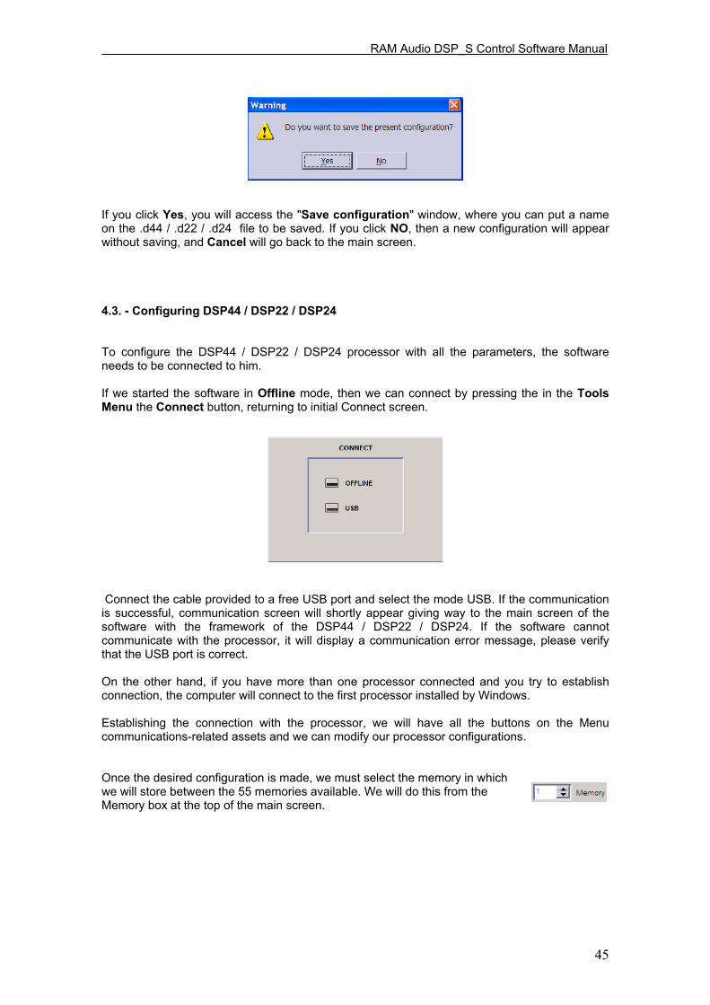
RAM Audio DSP_S Control Software Manual
45
If you click Yes, you will access the "Save configuration" window, where you can put a name on the .d44 / .d22 / .d24 file to be saved. If you click NO, then a new configuration will appear without saving, and Cancel will go back to the main screen. 4.3. - Configuring DSP44 / DSP22 / DSP24 To configure the DSP44 / DSP22 / DSP24 processor with all the parameters, the software needs to be connected to him. If we started the software in Offline mode, then we can connect by pressing the in the Tools Menu the Connect button, returning to initial Connect screen. Connect the cable provided to a free USB port and select the mode USB. If the communication is successful, communication screen will shortly appear giving way to the main screen of the software with the framework of the DSP44 / DSP22 / DSP24. If the software cannot communicate with the processor, it will display a communication error message, please verify that the USB port is correct. On the other hand, if you have more than one processor connected and you try to establish connection, the computer will connect to the first processor installed by Windows. Establishing the connection with the processor, we will have all the buttons on the Menu communications-related assets and we can modify our processor configurations. Once the desired configuration is made, we must select the memory in which we will store between the 55 memories available. We will do this from the Memory box at the top of the main screen.

RAM Audio DSP_S Control Software Manual
46
Use the button Write to the Processor to save into the selected memory. While establishing connection Communications screen appears, showing Info of the status of the communication (initialization, checks, communications and end of this one) and the progress bar shows the percentage of the entire transmission. Once the transmission data is finished, the processor will move to that memory automatically, in order to start working in that one and "hear" the changes made. Every time you want to save the changes made into the same memory you will be asked if you are sure you want to "overwrite" the data in the same place. With the button "Execute Memory" you can change to an inactive memory and make it active, changing to the memory selected in the Memory box. 4.4. - Security On many occasions you should block the access to the controls of the processor, avoiding undesired persons modifying the parameters, especially in fixed installations or when renting equipment and you do not want anyone to change any settings, like limiters for example. We have three security/blocking levels in every model of the DSP_S Modules, DSP44 / DSP22 / DSP24. To activate the Security Main screen, click on the Icon in the Main Screen called "Security"

RAM Audio DSP_S Control Software Manual
47
The following screen will appear: You will see these three levels:
Level 0: Enable access: unlock Keyboard. You allow using every button of the processor. Level 1: Only Preset changing. Level 2: Disable access: lock all keyboard, no change can be made.
ZONE ACCESS: From the top of the Main screen, we can choose or decide to which zones the user will be allowed to modify parameters. By default software starts in an "Open" mode which allows you to access every zone without restrictions. Just click in the boxes on "Access to zones" it will deactivate permissions to access there. When you restrict access to zones, icons change and you are not able to see any parameter information, they will look like this:

RAM Audio DSP_S Control Software Manual
48
After selecting zones to allow access, select Closed Mode in the main screen and you will be asked for a password. This selection can be made on the drop down menu in the Preset Information section. You have two Modes to access: - Closed Mode: User can only access the zones activated, (remember: to activate this mode you will be asked for a password) - Open Mode: There are no restrictions to any place in the software, you can modify all parameters. But if you come from a Closed mode, you will be asked for the password again. 4.5. - Updating internal DSP Program As in all fields of computer science, evolution is constant. DSP_S module is a Live product in constant evolution. To ensure your DSP_S module is always updated with the latest version of the internal DSP, you have the option to upgrade it through the software itself and through the RAM Audio website (www.ramaudio.com) you can download updates and improvements for your DSP_S module. If you click on the DSP Icon, the following warning message will appear: Once the installation of the new Software is completed, your processor will have the latest improvements and upgrades until the next version is available.

RAM Audio DSP_S Control Software Manual
49
All rights reserved. Any reproduction, total or partial of this manual by any means without the written permission of RAM Audio is totally forbidden. RAM Audio shall not be liable to the buyer of this product or with third parties for damages, losses, costs or expenses they may incur on the buyer or third parties as a result of an accident, misuse or abuse of this product and any amendments, repairs or alterations in it, or not so absolutely strictly observe the instructions of operating and maintaining given by RAM Audio. DSP_S Control Software, DSP44, DSP22 and DSP24 are trademarks of RAM Audio. Microsoft and Windows are registered trademarks of Microsoft Corporation. Other product names used in this documentation are only for identification purposes and they are trademarks of their respective owners. Copyright© 2008 RAM Audio All rights reserved. Edited in Spain by RAM Audio 1ª Edition January 2009.
Manufactured by C.E. Studio-2 s.l. Pol. Ind. La Lloma, C/ Sierra Parenxisa, nº 28
46960 Aldaya, Valencia SPAIN www.ramaudio.com [email protected]