professional services description for the · pdf filerev 1 – dec. 23, 2009 1...
TRANSCRIPT

Rev 1 – Dec. 23, 2009 1
PROFESSIONAL SERVICES DESCRIPTION FOR THE POSITION OF:
Paulsboro Marine Terminal
Monitoring Well Extension Services
SUBMISSION DEADLINE:
January 12, 2010 at 2:00 P.M.
FAIR AND OPEN PUBLIC SOLICITATION PROCESS FOR PROFESSIONAL SERVICES
FOR
GLOUCESTER COUNTY IMPROVEMENT AUTHORITY 109 BUDD BOULEVARD
WOODBURY, NEW JERSEY 08096

Rev 1 – Dec. 23, 2009 2
Through this Request for Qualifications/Proposals, the Authority, on behalf of the South Jersey Port Corporation (SJPC) seeks to engage a specialty consultant for the term from the date the successful contractor is issued a notice to proceed letter until completion of the work on or before December 31, 2010. This contract will be awarded through a fair and open process pursuant to N.J.S.A.. 19:44A-20.4 et seq. The Specialty Consultant’s Standard Requirements of Technical Proposal (items A thru M) and Cost Proposal must be received and will be publicly opened and read aloud on January 12, 2010 at 2:00 P.M. at the GCIA administrative office located at 109 Budd Boulevard, Woodbury, New Jersey. Each specialty consultant is advised that compliance with the “Fair and Open Standardized Submission Requirements and Selection Criteria” is required. These requirements must be obtained by contacting Danae Ciociola or Megan Kerr of the GCIA at 856-848-4002. The following is a description of the professional services needed including, where appropriate, a brief description of the tasks involved: Scope of Services In support of the Paulsboro Marine Terminal development program, a New Jersey licensed driller shall perform the following scope of work.
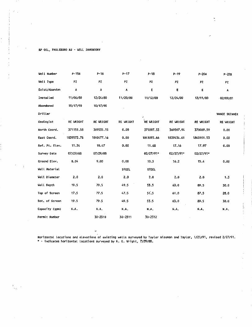
For Monitoring Wells – with stickup/standpipe protection Furnish and install the necessary labor, equipment and materials to provide the following unless otherwise noted. The activities below apply to the first 11 wells listed in Attachment 1. Refer to Attachment 2 for an approximate location of the Monitoring Wells. Specifications for raising the elevation and providing temporary protection of these wells during subsequent earthwork operations (by others) are provided on Attachment 3 and further described below. .
1. Site grading work (by others) will be provided for readily accessible access to the existing monitoring wells by rubber tired truck mounted equipment
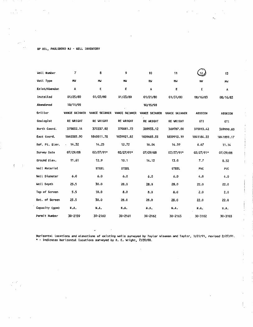
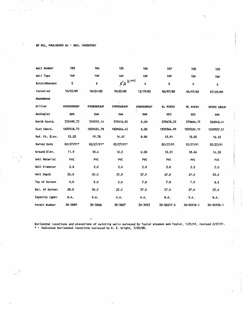
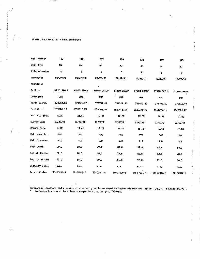
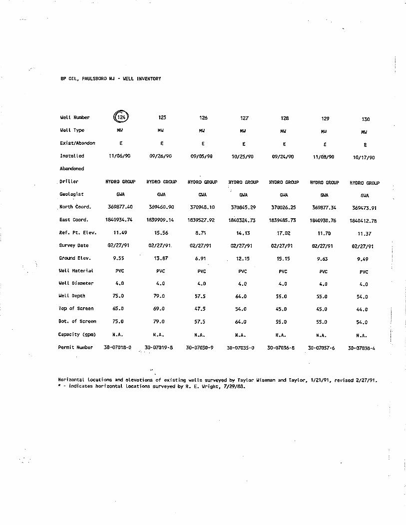
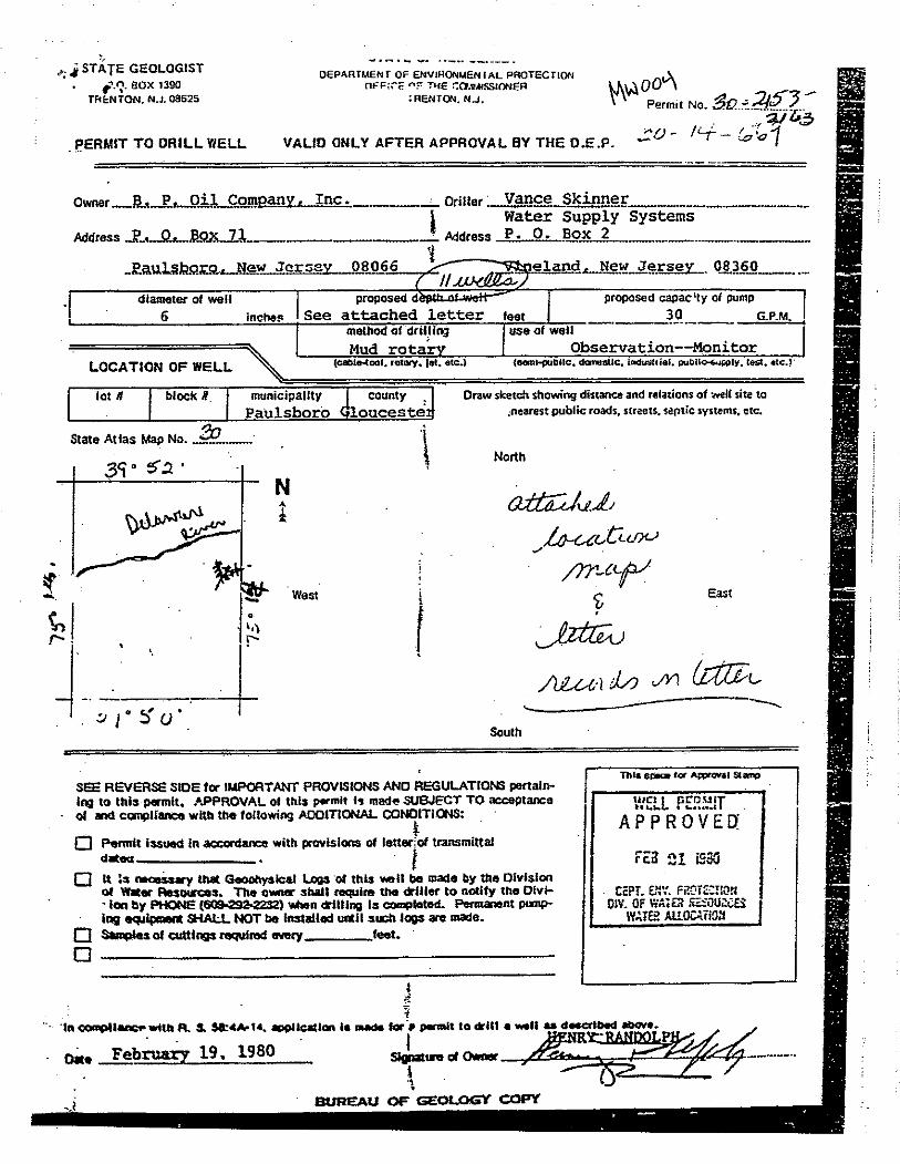
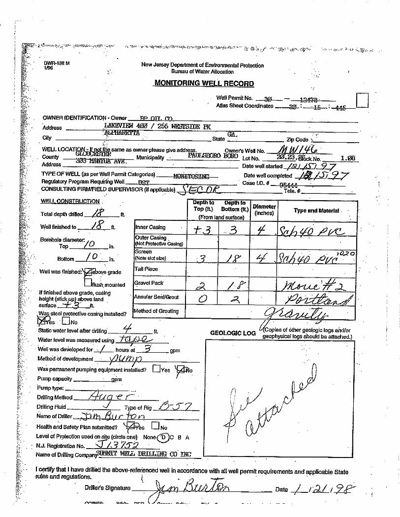
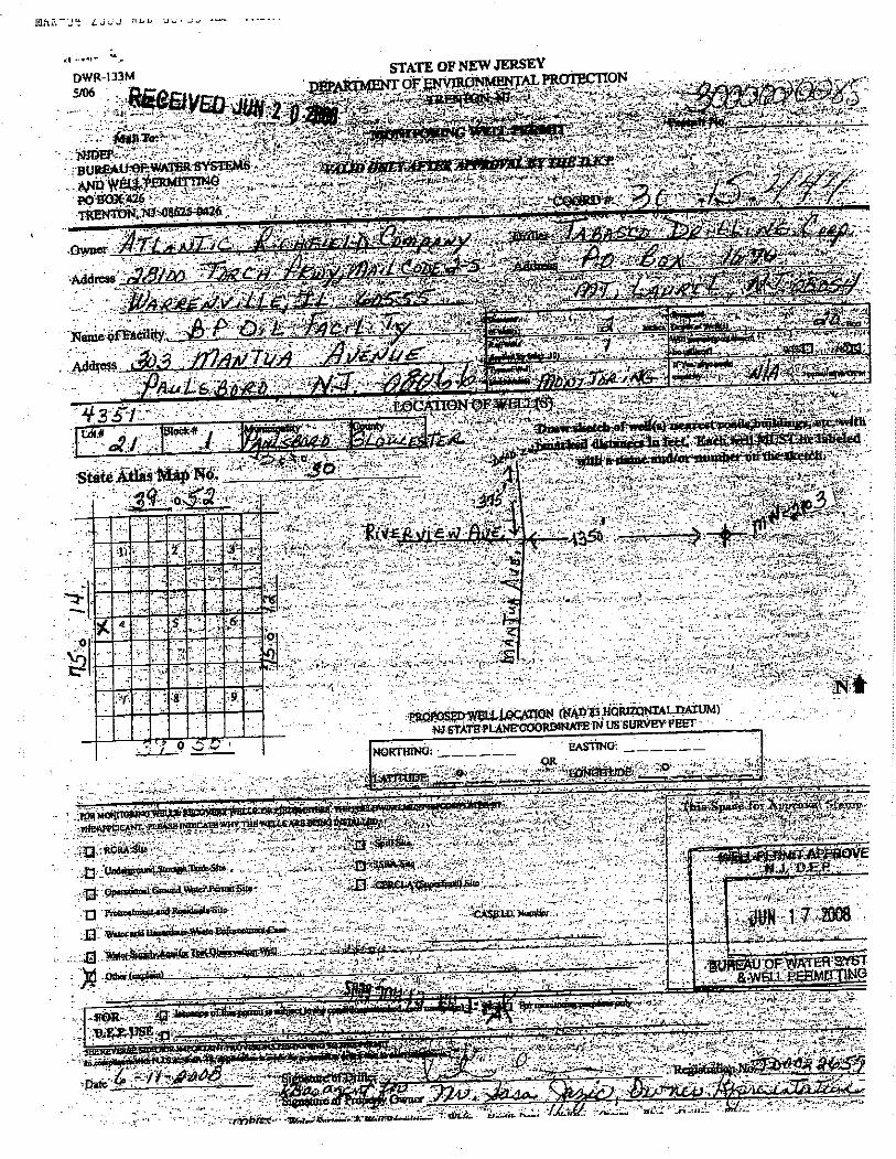
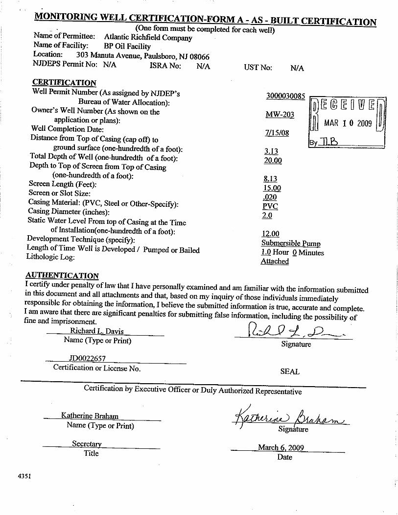
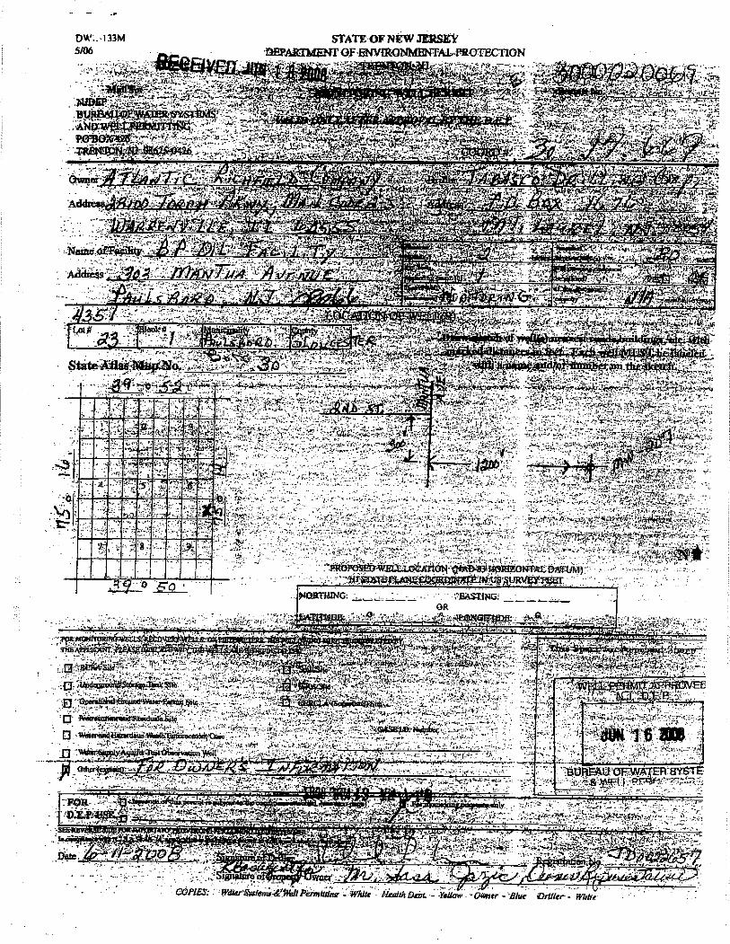
2. Obtain a NJDEP well permit for modification. Refer to Attachment 5 for a copy of the existing New Jersey Monitoring Well Permit per well identification number.
3. Remove existing protective steel standpipe.
4. Extend PVC well casing per specification and proposed rough grade. Furnish and
install new locking cap at top of casing.
5. Excavate around well casing to a depth of 3 ft below original (existing ground elevation) grade

Rev 1 – Dec. 23, 2009 3
6. Furnish and install double wall black HDPE corrugated storm water pipe
(protective collar) or equivalent over modified well casing. Refer to Attachment 6 for a protective well collar specification. Protective collar is to be centered around well casing. Temporary bracing can be used to maintain alignment of protective collar. Upper end of temporary brace can be screwed into outer wall of protective collar.
7. Backfill excavation with excavation spoils. Backfill to be raised in 6" lifts.
8. Compact each lift using a vibratory plate compactor
9. Place fill within annular space between protective collar and well casing to the
elevation of original grade.
10. Fill material to be placed and compacted around the stick-up monitoring well to the proposed rough grade (by others). From a timing perspective, the placement of fill material by others is projected to require upwards of six to eight (8) weeks to complete the fill process. For pricing purposes, the Specialty Consultant is to plan on requiring two separate time intervals (i.e. at 4 weeks and 8 weeks after commencement of fill material) for completing steps 10 and 11 for each of the well extensions.
11. Following the completion of the fill work by others, fill annular space between
protective collar and well casing with light weight concrete.
12. Light weight concrete shall be placed up to a height that is 12” less than the “Proposed rough grade" as indicated in Attachment 3.
13. Upon completion of the well extension work, the Specialty Consultant is to
survey the new well locations via GPS or similar surveying data
14. Upon completion of the well extension work, the Specialty Consultant is to incorporate the GPS and other data necessary in order to submit to the NJDEP within 90 days of installation the required completion report or well record for each well.
Former Recharge Well This procedure applies to protect recharge well RC-1 which is listed in Attachment 1. RC-1 is an 18-inch diameter 33-foot deep former groundwater re-injection well. This well is to be protected and its elevation raised in compliance with the previously described procedure for protection of monitoring wells with stickups/standpipes. The specific changes from the method for protection of monitoring wells shall include:

Rev 1 – Dec. 23, 2009 4
1. Furnish and install a Fernco coupling to extend existing casing with PVC riser (see
Attachment 3).
2. Furnish and install a larger diameter protective collar. Inactive Recovery Wells This procedure applies to protect and raise one inactive recovery well, listed in Attachment 1. R-3 is a 12-inch diameter, 85 foot deep former groundwater recovery well. This well is to be protected and its elevation raised in compliance with the previously described procedure for protection of monitoring wells and as indicated for former recharge well RC-1 (above). Specifications for recovery well R-3 is provided on Attachment 4. Potable water is not available on-site therefore Specialty Consultant to incorporate needs within its scope of work.
SCHEDULE Upon receipt of a Notice-To-Proceed, the Specialty Consultant shall commence the work within a period of 5 business days. A notice to proceed is targeted for late January 2010. The Specialty Consultant is to include a bar chart schedule that depicts the time frame required for each well to be extended as indicated above. COST PROPOSAL FORMAT GCIA requires that you provide a lump sum price per monitoring well identification number listed in Attachment 1. The lump sum price per well is to include all labor and materials to complete the scope of work detailed above. Refer to ATTACHMENT 7 for the format for the Specialty Consultants TOTAL COST PROPOSAL. INSURANCE Consultant is to include a copy of proposed insurance coverage with the technical proposal documents. In addition to the GCIA, BP North America and the South Jersey Port Corporation are to be included as additional insured.

ADS, Inc. Drainage Handbook Specifications ♦ 1-17 ________________________________________________________________________________________________
© ADS, Inc., October 2009
ADS N-12® PLAIN END PIPE (per ASTM F2648) SPECIFICATION Scope This specification describes 4- through 60-inch (100 to 1500 mm) ADS N-12 plain end pipe (per ASTM F2648) for use in gravity-flow land drainage applications. Pipe Requirements ADS N-12 plain end pipe (per ASTM F2648) shall have a smooth interior and annular exterior corrugations. • 4- through 60-inch (100 to 1500 mm) shall meet ASTM F2648. • Manning’s “n” value for use in design shall be 0.012. Joint Performance Pipe shall be joined with coupling bands covering at least two full corrugations on each end of the pipe. Standard connections shall meet or exceed the soil-tight requirements of ASTM F2648. Gasketed connections shall incorporate a closed-cell synthetic expanded rubber gasket meeting the requirements of ASTM D1056 Grade 2A2. Gaskets, when applicable, shall be installed by the pipe manufacturer. Fittings Fittings shall conform to ASTM F 2306. Material Properties Material for pipe production shall be an engineered compound of virgin and recycled high density polyethylene conforming with the minimum requirements of cell classification 424420C (ESCR Test Condition B) for 4- through 10-inch (100 to 250 mm) diameters, and 435420C (ESCR Test Condition B) for 12- through 60-inch (300 to 1500 mm) diameters, as defined and described in the latest version of ASTM D3350, except that carbon black content should not exceed 4%. The design engineer shall verify compatibility with overall system including structural, hydraulic, material and installation requirements for a given application. Installation Installation shall be in accordance with ASTM D2321 and ADS recommended installation guidelines, with the exception that minimum cover in trafficked areas for 4- through 48-inch (100 to 1200 mm) diameters shall be one foot. (0.3 m) and for 60-inch (1500 mm) diameters, the minimum cover shall be 2 ft. (0.6 m) in single run applications. Backfill for minimum cover situations shall consist of Class 1 (compacted), or Class 2 (minimum 90% SPD) material. Maximum fill heights depend on embedment material and compaction level; please refer to Technical Note 2.02. Contact your local ADS representative or visit our website at www.ads-pipe.com for a copy of the latest installation guidelines.
Pipe Dimensions
Nominal Diameter Pipe I.D. in (mm)
4 (100)
6 (150)
8 (200)
10 (250)
12 (300)
15 (375)
18 (450)
24 (600)
30 (750)
36 (900)
42 (1050)
48 (1200)
60 (1500)
Pipe O.D.* in (mm)
4.8 (122)
6.9 (175)
9.1 (231)
11.4 (290)
14.5 (368)
18 (457)
22 (559)
28 (711)
36 (914)
42 (1067)
48 (1219)
54 (1372)
67 (1702)
Perforations All diameters available with or without perforations. *Pipe O.D. values are provided for reference purposes only, values stated for 12- through 60-inch are ± 1 inch. Contact a sales representative for exact values.


Rev 1 – Dec. 23, 2009 5
PAULSBORO MARINE TERMINAL MONITORING WELL EXTENSION SERVICES
COST PROPOSAL
Number
Well Identification
No.
COST PER WELL
($) 1 MW-4
2 MW-12
3 MW-19
4 MW-22
5 MW-124
6 MW-146
7 MW-150
8 MW-165
9 MW-181
10 MW-203
11 MW-207
12 R-3
13 RC-1
14 EMW – 1B
15 EMW – 14
16 EMW-4
17 EMW-7
TOTAL
TOTAL COST PROPOSAL (in words) _____________________________________________