professionalwifiweatherstation usermanual 1.introduction 3
TRANSCRIPT
1
Professional WIFI Weather StationUser Manual
1.IntroductionThank you for your purchase of the FT0330 Professional WIFI Wireless Weatherstation. The following user guide provides step by step instructions for installation,operation and troubleshooting.
2.WarningsWarning: Any metal object may attract a lightning strike, including your weatherstation mounting pole. Never install the weather station in a storm.Warning: Installing your weather station in a high location may result in injury ordeath. Perform as much of the initial check out and operation.
3.Getting StartedThe weather station consists of a display console (receiver), a sensor array withIntegrated Outdoor Transmitter and mounting hardware.
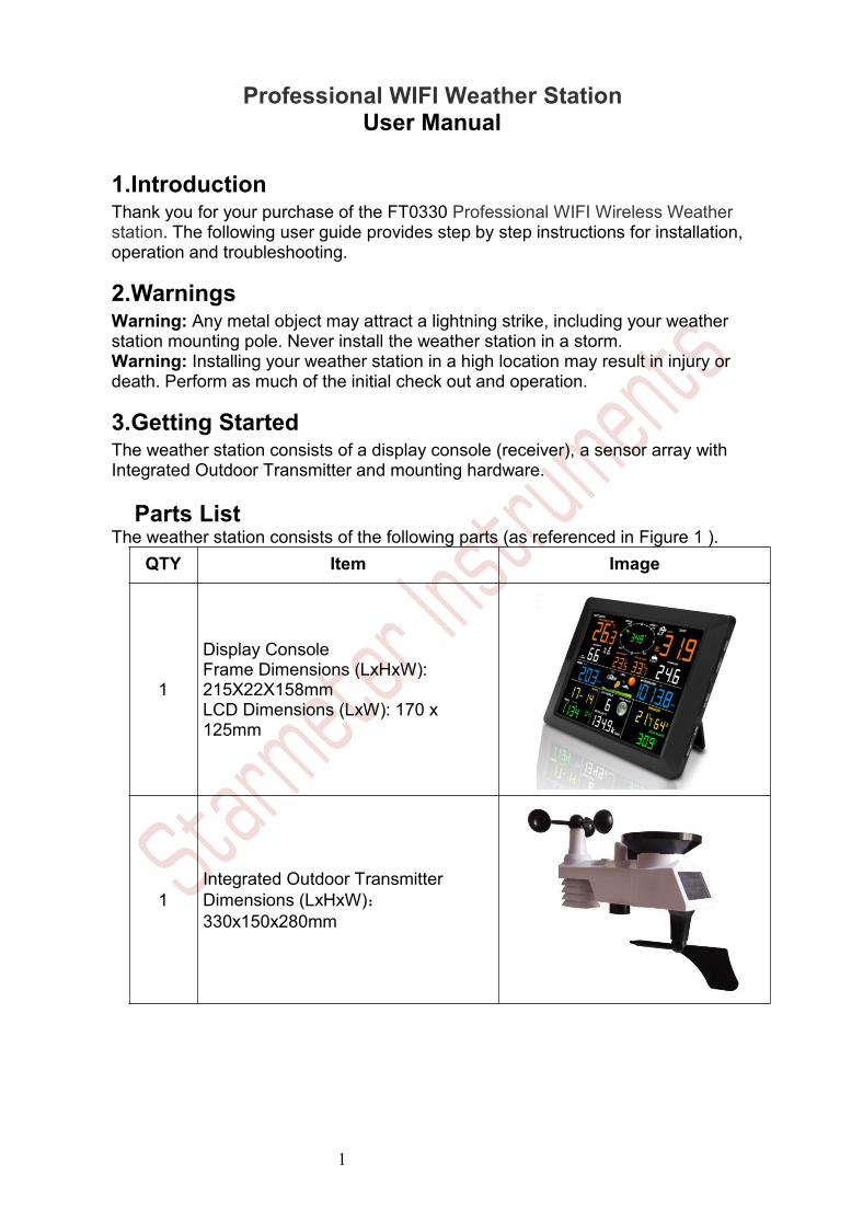
Parts ListThe weather station consists of the following parts (as referenced in Figure 1 ).
QTY Item Image
1
Display ConsoleFrame Dimensions (LxHxW):215X22X158mmLCD Dimensions (LxW): 170 x125mm
1Integrated Outdoor TransmitterDimensions (LxHxW):330x150x280mm

2
QTY Item Image
1 Foot Mounting (with pole insert)Dimensions: 84x 152 x 216mm
1
Mounting Bracket Back Plate (polemount)
Dimensions: 76 x 102 x 38mm
1 Mounting PoleDimensions: 76 x 76 x 25mm
2 Pole mounting nuts (M3) / bolts Ø3)
4 Pole mounting nuts (M5) / bolts ( Ø5)
4 Tapping screws
1 Manual

3
QTY Item Image
1 Power Adapter
Figure 1
3.2 Recommend Tools● Precision screwdriver (for small Phillips screws)● Compass or GPS (for wind direction calibration)● Adjustable Wrench
3.3 Sensor Assembly Set UpThe following illustration shows the full segment for Thermo-Hygrometer,WIND,RAIN and UV INDEX sensor.purposes only ,as shown in Figure 2.
Figure 2
3.3.1 Insert batteries into the transmitter. Locate the battery door on thetransmitter, push and open the battery compartment, as show in Figure 3.

4
Figure 3
Remove the battery door on the back of the sensor by removing the set screw, asshown in Figure 4.
Figure 4
Inserting 3xAA batteries in the battery compartment, as show in Figure 5.

5
Figure 5
Close the battery door. Make sure the gasket (around the battery compartment)is properly seated in its trace prior to closing the door. Tighten the set screw.Note: Do not install the batteries backwards. You can permanently damage the
sensors. The solar panel does not charge the batteries, so rechargeable batteriesare not needed or recommended.
Note:We recommend installing Lithium AA batteries for sensors.The sensor LED indicator will light for 3 seconds, and then flash once per 16seconds thereafter. Each time it flashes, the sensor is transmitting data.Replace the battery door and push to tighten it.
Note: If the sensor does not power up after inserting the batteries, press thereset button shown in Figure 6.

6
Figure 6
3.4 Display Console3.4.1 Display Console LayoutThe display console layout is shown in Figure 10
Note: The following illustration shows the full segment LCD display fordescription purposes only and will not appear like this during normal operation.
Figure 101. Outdoor temperature display2. WIFI network3. Outdoor humidity display4. Outdoor humidity HI/LO alarmicon5. Min/Max reset for 24h icon6. Weather forecast7.Rainfall display(RATE, 24h,WEEK,MONTH, TOTAL)
8. Rainfall units of measure9. Date display10. Time alarm icon11. Time and Year12. UV Index display13. Sunshine intensity14. MOON phase15. Sunlight units of measure16. Indoor Dew point display17. Indoor Dew point ICON
18. Indoor temperature and humiditydisplay19. Pressure (REL and ABS) display20. Pressure units of measure21. Wind speed average display22.Wind gust display23.Wind speed units of measure24.Wind chill and feels like HI/Lo alarmicon25. Wind direction26. OUT dew point and AT(ApparentTemperature) display icon27. Integrated outdoor transmitter Lowpower indicator28.Temperature units (°F or °C)29.Outdoor temperature HI/LO alarmicon
3.4.2Display Console Set Up

7
It is recommended to plug in the power supply to reduce thebattery consumption and extend the service life.
Note: The sensor array must be powered and updating before powering up the console,or theconsole will time out searching for the sensor. Power the console last.
Make certain the weather station sensor array is at least 3m away from the console and within30m of the console. If the weather station is too close or too far away, it may not receive aproper signal.
Remove the battery door on the back of the display, as shown in Figure 11. Insert three AAA(alkaline or lithium) batteries in the back of the display console. The display will beep once andall of the LCD segments will light up for a few seconds to verify all segments are operatingproperly.
Note: The character contrast is best from a slightly elevated viewing angle.
Figure 11
Replace the battery door, and fold out the desk stand and place the console in theupright position.
The unit will instantly display indoor temperature, humidity, pressure, tendency,moon phase, and time. The wind speed, wind gust, wind direction, rain,UV/Sunlight , Integrated outdoor temperature and humidity will update on thedisplay within a few minutes. Do not Press any menu buttons until the outsidetransmitter report in, otherwise the outdoor sensor search mode will be terminated.When the outdoor transmitter data has been received, the console willautomatically switch to the normal mode from which all further settings can beperformed.
While in the search mode, the remote search icon will be constantly displayed.

8
If it does not update, please reference the troubleshooting guide in Section 18.Note: The power adapter is intended to be correctly oriented in a vertical or
floor mounted position. The prongs are not designed to hold the plug in place if it isplugged into a ceiling, under-the-table or cabinet outlet.
Figure 12
Note: If the power adapter is plugged in, BL ON will display in the time area forthree seconds when powered up. Conversely, if the power adapter is not pluggedin, AC OFF will be displayed, the icon will display .
4.Weather Station Installation4.1 Pre Installation Checkout Before installing your weather station in thepermanent location, we recommend operating the weather station for oneweek in a temporary location with easy access. This will allow you to check outall of the functions, insure proper operation, and familiarize you with the weatherstation and calibration procedures. This will also allow you to test the wirelessrange of the weather station.4.2 Site SurveyPerform a site survey before installing the weather station. Consider the following:1. You must clean the rain gauge once per year and change the batteries everytwo years. Provide easy access to the weather station.2. Avoid radiant heat transfer from buildings and structures. In general, install thesensor array at least 5’ from any building, structure, ground, or roof top.3. Avoid wind and rain obstructions. The rule of thumb is to install the sensor arrayat least four times the distance of the height of the tallest obstruction. For example,if the building is 6m tall, install 4 x 6m = 24m away. Use common sense. If theweather station is installed next to a tall building, the wind and rain will not beaccurate.4. Wireless Range. The radio communication between receiver and transmitter inan open field can reach a distance of up to 100 m, providing there are no

9
interfering obstacles such as buildings, trees, vehicles, high voltage lines. Wirelesssignals will not penetrate metal buildings. Most applications will only reach 30mdue to building obstructions, walls and interference.5. Radio interference such as PCs, radios or TV sets can, in the worst case,entirely cut off radio communication. Please take this into consideration whenchoosing console or mounting locations.
4.3 Best Practices for Wireless CommunicationWireless communication is susceptible to interference, distance, walls and metalbarriers. We recommend the following best practices for trouble free wirelesscommunication.1. Electro-Magnetic Interference (EMI). Keep the console several feet away fromcomputer monitors and TVs.2. Radio Frequency Interference (RFI). If you have other 433 MHz devices andcommunication is intermittent, try turning off these other devices fortroubleshooting purposes. You may need to relocate the transmitters or receiversto avoid intermittent communication.3. Line of Sight Rating. This device is rated at 100 m line of sight (no interference,barriers or walls) but typically you will get 30 m maximum under most real-worldinstallations, which include passing through barriers or walls.4. Metal Barriers. Radio frequency will not pass through metal barriers such asaluminum siding. If you have metal siding, align the remote and console through awindow to get a clear line of sight.The following is a table of reception loss vs. the transmission medium. Each“wall”or obstruction decreases the transmission range by the factor shown below.
Medium RF Signal Strength Reduction
Glass (untreated) 5-15%
Plastics 10-15%
Wood 10-40%
Brick 10-40%
Concrete 40-80%
Metal 90-100%
5.Final Installation of SensorsIntegrated outdoor transmitter installation.Professional Wireless Weather Station can be used in both the Northern andSouthern Hemispheres.Prior to installation, you will need to calibrate the wind direction.
5.1. NorthernHemispheres (NOR).

10
The cardinal directions (N, S, E, W) molded on the body of the outdoor sensor areindicators for the Northern Hemisphere only.
Step 1:There is a “S” indicator on the wind vane that indicates South, as shown inFigure 13. Align this “S” marker in the direction of South.Step 2: Console operation is set to NorthernHemispheres( NOR in the time area)in Location division.
Note:There are four alphabet letter of “N”,”E”,”S”and “W” around the winddirection, representing for the direction of North, East, South and West. Winddirection sensor has to be adjusted so that the directions on the sensor arematching with your real location. Permanent wind direction error will be introducedwhen the wind direction sensor is not positioned correctly during installation.
NorthernHemispheres
Southern Hemispheres
Figure 13
5.2. SouthernHemispheres (SOU).For Southern Hemisphere installations, ignore these(N, S, E, W) and face thesolar panel to the North (and in a sunny position) when it comes to installing theIntegrated outdoor transmitter.
Step 1: Install the Integrated outdoor transmitter and face the solar panelNorth.

11
Step 2: Console operation is set to SouthernHemispheres( SOU in the time area)in Location division.
Note:Wind direction sensor has to be adjusted so that the directions on thesensor are matching with your real location. Permanent wind direction error(readapproximately 180º)will be introduced when the wind direction sensor is notpositioned correctly during installation.
Fasten the integrated transmitter to mounting pole brackets with foot-mounting,two ¢3 bolts and M3 nuts , as shown in Figure 14
Figure 14
Tighten the mounting pole to your existing mounting pole with the four¢5 Boltsand M5 Nuts assembly, or fix on the wall with four tapping screw, as shown inFigure15.

12
Figure 15
6.Low Battery Icon.
A low battery indicator icon is shown in the display window for Integrated outdoortransmitter. When the low battery icon appears (the battery voltage is lower than

13
3.6V), replace the batteries in the sensor with fresh batteries. Be sure to never mixold and new batteries, and never mix battery types such as alkaline and lithiumtogether.
7.Console OperationNote: The console has five keys for easy operation: MIN/MAX/-key, ALARM
key, SET/MODE key, CHANNEL/+ andSNOOZE key.
7.1 Quick Display ModeNote: To exit the Quick Display Mode at any time, press the SNOOZE key of
the display console.
While in Normal Mode, press (do not hold) the SET/MODE key to enter the QuickDisplay Mode as follows:
once for time, time/week and second, Twice for rainfall three for outdoor dew point temperature. four for wind average Five for pressure
1.Time, Time/Week and Second. Press the CHANNEL/+ or MIN/MAX/- key totoggle between time, time/week and second.2.Rainfall. Press the CHANNEL/+ or MIN/MAX/- key to toggle between rate, 24h,week, month and total.To clear the total rain, press the CHANNEL/+ or MIN/MAX/- button until total rainis displayed. The total rain will flash.Press and hold the SET button for fiveseconds until total rain reads 0.0.3.Outdoor Dew Point.Press the CHANNEL/+ or MIN/MAX/- key to togglebetween AT(Apparent Temperature) and dew point.4.Wind Average.Press the CHANNEL/+ or MIN/MAX/- key to toggle betweencurrent,2mins and 10 minutes.5.Absolute Pressure and Relative Pressure.Press the CHANNEL/+ orMIN/MAX/- key to toggle between absolute pressure and relative pressure.
7.2 Set (Program) ModeWhile in Normal Mode, press and hold the SET(MODE) key for at least threeseconds to enter the Set Mode. The first setting will begin flashing. You can pressthe SET(MODE) key again to skip any step, as defined below.
Note: In the Set mode, press the [+] key or [-] key to change or scroll the value.Hold the [+] key or [-] key for three seconds to increase/decrease rapidly.
Note: To exit the Set mode at any time, press the SNOOZE button of thedisplay console.1. Time SYNC(default:ON).Press the SET key again to set the network time sync.
Press the [+] key or [-] key to switch between SYNCtime ON and SYNCtimeOFF of measure.
2. 12/24 Hour Format (default: 24h):.Press the SET(MODE) key again to adjustthe 12/24 hour format setting (FMT). Press the [+] key or [-] key to changebetween 12 hour and 24 hour format.

14
3. Change Hour.press the SET(MODE) key again to set the hour. Press the [+]key or [-]key to adjust the hour up or down. Note the PM icon is present duringafternoon hours.
4. Change Minute.Press the SET(MODE) key again to set the minute. Press the[+] key or [-] key to adjust the minute up or down.
5. Date Format (default: MM-DD): Press the SET(MODE) key again to enter theday/month format mode. Press the [+] key to switch between MM-DD, DD-MM.
6. Change Month.Press the SET(MODE) key again to set the calendar month.Press the [+] key or [-] key to adjust the calendar month.
7. Change Day.Press the SET(MODE) key again to set the calendar day. Pressthe [+] key or [-] key to adjust the calendar day.
8. Change Year. Press the SET(MODE) key again to set the calendar year.Press the [+] key or [-] key to adjust the calendar year.
9. Max/Min Clearing (default: ON). Press the SET(MODE) key again to set themax/min clearing mode (CLR). The Max/Min can be programmed to clear daily(at midnight) or manually. Press the [+] key or [-] key to switch between “Clears24h” and Clears Manually.
10.Temperature Units of Measure (default: °C):. Press the SET(MODE) keyagain to change the temperature units of measure (the UNITSET icon will bedisplayed). Press the [+] key or [-] key to switch between °F and °C units ofmeasure.
11.Wind Speed Units of Measure (default: m/s). Press the SET(MODE) keyagain to change the wind speed units of measure . Press the [+] key or [-] keyto toggle the wind speed units between m/s, km/h, mph, knots,ft/s or bft.
12.Rainfall Units of Measure (default: mm). Press the SET(MODE) key again tochange the Rainfall units of measure. Press[+] key or [-] key to toggle therainfall units between mm and inch.
13.Barometric Pressure Display Units(default: hPa). Press the SET(MODE)key again to change the pressure units of measure. Press the [+] key or [-] keyto toggle the pressure units between mmhg, inHg or hPa.
14.Pressure Threshold Setting (default level 2). Press the SET(MODE) keyagain to change the pressure threshold. Press the [+] key or [-] key to changepressure threshold 2 mbar/hour to 4 mbar/hour.(For detailed information of thispart please refer to 15.5)
15.Weather Icons Setting (default: partly cloudy).Press the SET(MODE) keyagain to change the initial weather icon. Press the [+] key or [-] key to select theinitial weather icon of Sunny, Cloudy, Partly Cloudy or Rainy. (For detailedinformation of this part please refer to 15.1 and 15.2)
16.Sunlight Display Units(default: W/㎡). Press the SET(MODE) key again tochange the sunlight units of measure. Press the [+] key or [-] key to toggle thesunlight units between ,W/㎡, fc or lux.
17. Location division.(default: Northern Hemisphere).Press the SET(MODE)key again to change the location division. Press the [+] key or [-] key to toggle thesunlight units Northern Hemisphere (NOR)or Southern Hemisphere(SOU). (referto 5.0 Final Installation of Integrated outdoor transmitter)
7.5 Reset Min/Max record
In normal mode, press (do not hold) the MIN/MAX/-key, the MAX icon will bedisplayed in date area. Press the SET/MODE key to view max values of rainfall

15
(rate, 24h, week or month) , pressure (ABS or REL),outdoor temperature andhumidity(AT or dewpoint)and indoor temperature and humidity (temp or dew point).
Press the MIN/MAX/- key for three seconds to clear all max values. (the rainfall,wind speed, wind gust, pressure, temperature and humidity maximum values. Themaximum values will now display the current values).
Press the MIN/MAX/- key again (do not hold), the MIN icon will be displayed.Press the SET/MODEkey to view min values of pressure (ABS or REL), outdoortemperature/humidity((AT or dew point),and indoor temperature/humidity(temp ordew point).
Press the MIN/MAX/- key for three seconds to clear all min values.(the pressure,temperature and humidity minimum values. The minimum values will now displaythe current values).
Press the SNOOZE key to exit the min/max checking and cleaning mode, return tonormal display mode.
7.6 Snooze ModeIf the alarm sounds, and you wish to silence the alarm, press the SNOOZE key,the backlight will turn on. The alarm icon will continue to flash and the alarm willsilence for five minute. press any key (MIN/MAX/+ ,SET/MODE,ALARM,CHANNEL/+) to permanently exit the Snooze mode.
7.7 Back light ModeIf the LED is off, Press the SNOOZE button once. The backlight will turn on for fiveseconds, and if no operation is performed for three seconds, the backlight will turnoff.
The backlight operation is different when operating on batteries to save power.
ADJUSTABLE BACKLIGHT BRIGHTNESSThere are 3 levels of brightness of backlight.When the backlight is on pressSNOOZE key to switch between the 3 levels.
When backlight is off, press and hold the SNOOZE key for two seconds, thebacklight will turn on permanently, and BL ON icon will be displayed for threeseconds in the date area.To turn off the backlight at any time press and hold the SNOOZE key for twoseconds.BL OFF icon will be displayed for three seconds in the date field.
Note: If plugged into AC power, the time area will display AC ON and thebacklight will remain on. It is not recommended leaving the backlight on for a longperiod of time when operating on batteries only, or the batteries will run downquickly.
8.Alarm ModeThe FT0310 includes the following alarms:
Time (There are two alarms for time. Alarm 1 and Alarm 2)

16
Outdoor Temperature Outdoor Humidity Outdoor AT(Apparent Temperature) Outdoor Dew Point Outdoor Feels Like Temperature Outdoor Dew Point Wind Gust Wind Average Rate Rainfall 24 Hour Rainfall Absolute Pressure Relative Pressure Indoor Temperature Indoor Humidity Indoor Dew Point UV Index Sunlight
8.1 Alarm OperationWhen an alarm condition is exceeded, the alarm icon will flash (visual) and thealarm beeper will sound (audible). To silence the beeper, press any key.
8.2 Viewing the High and Low AlarmsTo view the current alarm settings, press the ALARM key to enter the alarm mode.HI AL 1 will be displayed in the date area. At the same time Alarm 1 time and HIalarm parameters of indoor temperature/humidity, outdoor temperature/humidity,rain rate, AT, feels like, wind gust, wind average, absolute pressure, UV index,Sunlight are displayed. Press SET/MODE key to view Alarm 2 time and HI alarmparameters of indoor dew point, 24h rainfall, outdoor dew point, and relativepressure.
Press ALARM key again to view the LOW alarms along with the alarm clock timethe same way HI alarms.
Press the SNOOZE key at any time to return to the normal mode.
8.3 Setting the AlarmsPress ALARM key to enter the alarm mode.
Press and hold the SET/MODE key for three seconds. The first alarm parameterwill begin flashing (alarm hour).
To save the alarm setting and proceed to the next alarm parameter, Press (do nothold) the SET/MODE key.
To adjust the alarm parameter, press the [+] or [-] key to increase or decrease thealarm settings, or press and hold the [+] or [-] key for three seconds to increase ordecrease the alarm settings rapidly.

17
Press the ALARM key to turn on (the alarm icon will appear) and off the alarm.
Press the SNOOZE key once at any time to return to the normal mode. After 30seconds of inactivity, the alarm mode will time out and return to normal mode.
The following is a list of the individual alarm parameters that are set (in order):1. Alarm hour(alarm 1)2. Alarm minute(alarm 1)3. Alarm hour(alarm 2)4. Alarm minute(alarm 2)5. Outdoor temperature high alarm6. Outdoor temperature low alarm7. Outdoor humidity high alarm8. Outdoor humidity low alarm9. Outdoor AT high alarm10.Outdoor AT low alarm11.Outdoor dew point high alarm12.Outdoor dew point low alarm13.Outdoor feels like high alarm14.Outdoor feels like low alarm15.Wind Gust high alarm16.Wind Average high alarm17.Rainfall (RATE) high alarm18.Rainfall (24h) high alarm19.Absolute pressure high alarm20.Absolute pressure low alarm21.Relative pressure high alarm22.Relative pressure low alarm23.Indoor temperature high alarm24.Indoor temperature low alarm25.Indoor humidity high alarm26.Indoor humidity low alarm27.Indoor dew point high alarm28.Indoor dew point low alarm29.UV Index high alarm30.Sunlight high alarm
Note: To prevent repetitive temperature alarming, there is a 0.5 °C toleranceband. For example, if you set the high alarm to 26.7 °C and silence the alarm, thealarm icon will continue to flash until the temperature falls below 26.2°C, at whichpoint, the alarm will reset and must increase above 26.7 °C to activate again.
Note: To prevent repetitive alarming of humidity, there is a 4% tolerance bandin humidity alarm. For example, if you set the high alarm to 60% and silence thealarm, the alarm icon will continue to flash until the humidity falls below 56%, atwhich point, the alarm will reset and must increase above 60% to activate again.
8.4 Alarm and Command Key Beeper ON/OFF ModeThe beeper can be silenced for both alarms and key strokes.

18
In normal mode, press and hold the ALARM key for three seconds to toggle thebeeper on or off (depending on the current setting).
The BZON (beeper on) or BZOFF (beeper off) icon will appear in the time area forthree seconds.press and hold the ALARM key again for three seconds to togglethe BZON or BZOFF command.
9.WiFi Connection StatusWhen the console successfully connects to your Wi-Fi router, the Wi-Fi signal icon
will appear on the LCD display(behind the Outdoor humidity). If the Wi-Fisignal is not stable or the console is trying to connect to the router, the icon willflash. If the icon disappears, it means the console is not connected to the Wi-Firouter.
Note:If you own a dual band router (2.4 GHz and 5.0 GHz),make sure youconnect to the 2.4 GHz band, otherwise it will fail to connect the weatherstation to WiFi.
10. Time Server Sync StatusAfter the console has connected to the internet, it will attempt to connect to theinternet time server to obtain the time. Once the connection succeeds and theconsole’s time has updated, the SYNC icon will appear on the LCD. Thetime will automatically synchronize to the internet per an hour.
Note:Time synchronize method: Synchronized through internet UTCtime server.
WiFi Connection and Weather Servers11. Register with WeatherCloud.netNote: This is best done on a computer desktop or laptop.Visit : https://weathercloud.net/ and enter a Username, Email and Password(It isyour Login password of the websiteIt, not your email password. So noprivacy will be exposed).
11.1 Sign Up
1) Click Sign up as below
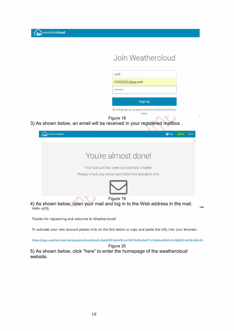
Figure 172) As shown below, enter a Username, Email and Password then Click Sign up.
19
Figure 183) As shown below, an email will be received in your registered mailbox .
Figure 194) As shown below, open your mail and log in to the Web address in the mail.
Figure 205) As shown below, click “here” to enter the homepage of the weathercloudwebsite.
20
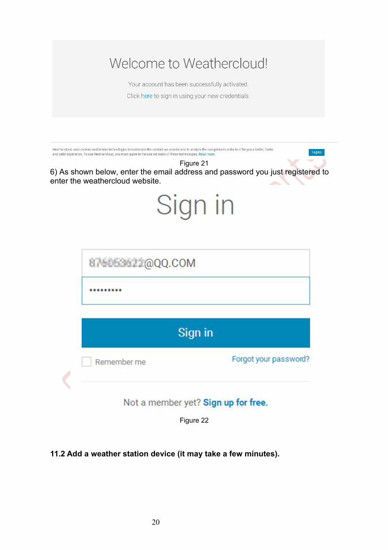
Figure 216) As shown below, enter the email address and password you just registered toenter the weathercloud website.
Figure 22
11.2 Add a weather station device (it may take a few minutes).

21
Figure 231) After sign up you will be prompted to add a device/ Select “Create
device” and enter your station’s information:Blanks with red * must be filled in.
Figure 24
Note: You can select any Model number and Link type in the above blanks.2) As shown below, click Get coordinates to identify your location of on the map,then click Done to confirm..
Figure 25
22
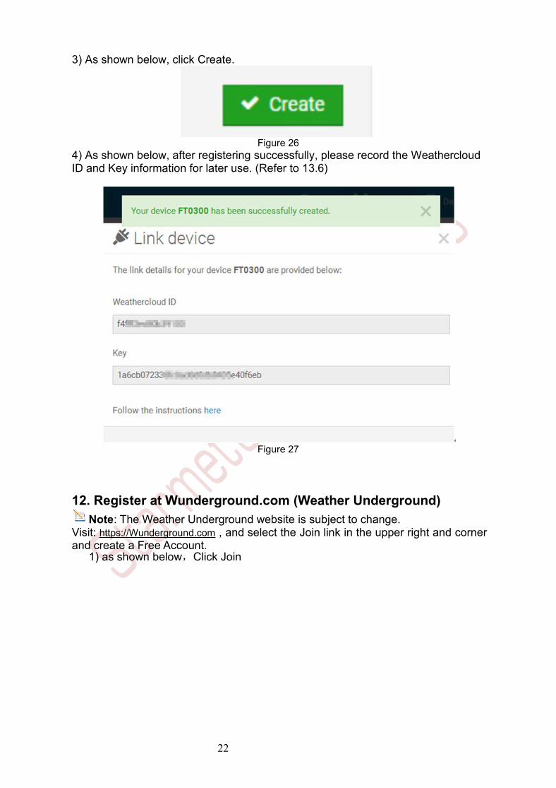
3) As shown below, click Create.
Figure 264) As shown below, after registering successfully, please record the WeathercloudID and Key information for later use. (Refer to 13.6)
Figure 27
12. Register at Wunderground.com (Weather Underground)Note: The Weather Underground website is subject to change.
Visit: https://Wunderground.com , and select the Join link in the upper right and cornerand create a Free Account.
1) as shown below,Click Join

23
Figure 28
2) As shown below, enter a Username, Email and Password(It is your Loginpassword of the websiteIt, not your email password.So no privacy will beexposed). Click Sign up for free.
Figure 29
3) As shown below, registration is done successfully.

24
Figure 30
4) As shown below, click Log in and enter the email address and password youjust registered.
Figure 315) As shown in the below, click My Profile. Then enter Member Settings.
Figure 32
6) As shown below, click Update home location.

25
Figure 33
7) As shown below, you will then be prompted to add a device/ Select “Add NewDevice
Figure 348) As shown below, click Personal Weather Station.
Figure 35
9) As shown below, select Address by inputting an address or select Manual to

26
position your address automatically. Then click Next:
Figure 36
10) As shown below, you will then be prompted to add a device/ Select “Createdevice” , then click I Accept and Next:Blanks with red (Required) must be filled in.Note: You can select any wifi weather station model in Device Hardware blank.

27
Figure 37
11) As shown below, after registering the host successfully, please recordStation ID and Station Key information for later use (refer to 13.6).
Figure 38
12) As shown below, registration is done successfully.

28
Figure 3913.WiFi Setup(Connect your Device to the Console’s WiFi)When you first power up(AC) the console, or press and hold the MIN/MAX/- buttonfor three seconds in normal mode, the console icon(behind the Outdoor humidity))
will flash to signify that it has entered WAP (wireless access point) mode,and is ready to enter for WIFI settings.
You can use your desktop, laptop, tablet, or smart phone to connect to theconsole’s WiFi. The console’s network name begins with WeatherHome, followedby a unique code.Note that when the console programming is complete, you will resume yourdefault WiFi connection.Note that you cannot connect two or more devices at the same time whenWAP mode.
13.1:Example 1: Connect to the console WiFi server with a PC.Choose WiFi network settings from Windows (or search “Change Wi-Fi Settings”from Windows), and Connect to the WeatherHome------ WiFi network, as shown inFigure 40 (your WiFi network name may be slightly different, but will always beginwith WeatherHome -).
Figure 40

29
13.2: Example 2. Connect to the console WiFi server with a Mac.
Choose the Settings icon and Network . Connect to the WeatherHome------ WiFi network, as shown in Figure 41 (your WiFi network name may be slightlydifferent, but will always begin with WeatherHome------ ).
Figure 41
13.3: Example 3. Connect to the console WiFi server with an iPhone or iPad.
Choose the Settings icon and Wi-Fi. Connect to the WeatherHome------ WiFinetwork, as shown in Figure 42 (your WiFi network name may be slightly different,but will always begin with WeatherHome------).
Figure 42

30
13.4: Example 4. Connect to the console WiFi server with an Android.
From the Apps icon, choose the Settings icon and Wi-Fi. Connect to theWeatherHome------ WiFi network, as shown in Figure 43 (your WiFi network namemay be slightly different, but will always begin with WeatherHome------ ).
Figure 43
13.5. Once connected, enter the following IP address into any browser’s addressbar:http://192.168.5.1to access the console’s web interface.
Note: Some browsers will treat 192.168.5.1 as a search, so make sure youinclude the header http://,or:http://192.168.5.1 not 192.168.5.1
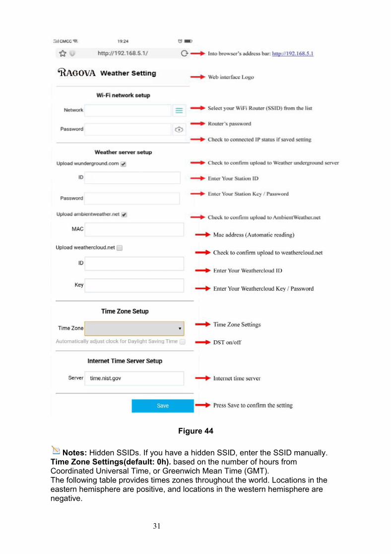
13.6. Enter the following information into the web interface (Figure 44). Make sureall of the information is entered prior to selecting Save. If you choose not to uploadWunderground.com, or upload weathercloud.net, leave the check boxesunchecked.
31
Figure 44
Notes: Hidden SSIDs. If you have a hidden SSID, enter the SSID manually.Time Zone Settings(default: 0h). based on the number of hours fromCoordinated Universal Time, or Greenwich Mean Time (GMT).The following table provides times zones throughout the world. Locations in theeastern hemisphere are positive, and locations in the western hemisphere arenegative.

32
Hoursfrom GMT
Time Zone Cities
-12 IDLW: International Date Line West ---
-11 NT: Nome Nome, AK
-10 AHST: Alaska-Hawaii StandardCAT: Central AlaskaHST: Hawaii Standard
Honolulu, HI
-9 YST: Yukon Standard Yukon Territory
-8 PST: Pacific Standard Los Angeles, CA, USA
-7 MST: Mountain Standard Denver, CO, USA
-6 CST: Central Standard Chicago, IL, USA
-5 EST: Eastern Standard New York, NY, USA
-4 AST: Atlantic Standard Caracas
-3 --- São Paulo, Brazil
-2 AT: Azores Azores, Cape VerdeIslands
-1 WAT: West Africa ---
0 GMT: Greenwich MeanWET: Western European
London, England
1 CET: Central European Paris, France
2 EET: Eastern European Athens, Greece
3 BT: Baghdad Moscow, Russia
4 --- Abu Dhabi, UAE
5 --- Tashkent
6 --- Astana
7 --- Bangkok
8 CCT: China Coast Bejing
9 JST: Japan Standard Tokyo
10 GST: Guam Standard Sydney

33
Hoursfrom GMT
Time Zone Cities
11 --- Magadan
12 IDLE: International Date Line EastNZST: New Zealand Standard
Wellington, NewZealand
13.7. If all of the information you entered is correct press save to confirm(Figure45). If it does not, check your web interface information again.
Figure 45
13.8. Once the setup is completed, disconnect your device from the console WiFi.Otherwise,the console will automatically exit WAP mode. (Figure 46)
Figure 46
If the connection is successful,the Wi-Fi console’s status Wi-Fi icon willstop flashing and remain on.
NOTE:When the console successfully connects to your any website ofweather servers, the data signal icon will appear on the LCD display(behind theOutdoor humidity). If the data signal icon is flashing, the console is currently

34
uploading to the server. If the icon disappears, the console is not connected tothe weather server for more than 30 minutes.
13.9 Viewing your Data on Weather UndergroundVisit:http://www.wunderground.com/personal-weather-station/dashboard?ID=STATIONIDwhere STATIONID is your personal station ID (example, KCALOSAN782).
Figure 47Multiple Sensor FeaturesWunderground.com does not support multiple sensor channels.Note: The current temperature and humidity data is the Integrated Outdoor
Transmitter.13.10. View your data on Weathercloud.Visit the website www.weathercloud.net and sign in with your e-mail address andpassword. Then you will go to the weather data of your weather stationautomatically.
14. Upgrade firmware
You may get the latest firmware of the console as below
14.1. When you first power up(AC) the console, or press and hold the MIN/MAX/-(WiFi) button for three seconds in normal mode, the console icon(behind the Outdoor
humidity)) will flash to signify that it has entered WAP (wireless access point)mode, and is ready to enter for WIFI settings.
`14.2. Use your smart phone, tablet, or computer to connect to the console throughWiFi(reference: Example 1-4 of WiFi Setting ).
14.3.Once connected, enter the following IP address into the browser’s addressbar: http://192.168.5.1/upgrade.html

35
Figure 48
14.4.Once connection succeeds, it will jump to “Upload Setting” screenautomatically.
Figure 49
14.5. Press Select File key to select the upgraded firmware as figure 50.
Figure 50
14.6. If update successfully when press Upgrade key. Then you will see.
Figure 51

36
NOTE: In this upgrade only Wifi firmware is updated. The console does not reset.
14.7.Once the upgrade is completed, the console will automatically exit WAPmode.
15. Other Console FeaturesThe following section describes additional features and display icons.
15.1 Weather ForecastingNote: The weather forecast or pressure tendency is based on the rate of
change of barometric pressure. In general, when the pressure increases, theweather improves (sunny to partly cloudy) and when the pressure decreases, theweather degrades (cloudy to rain).
The weather forecast is an estimation or generalization of weather changes in thenext 24 to 48 hours, and varies from location to location. The tendency is simply atool for projecting weather conditions and is never to be relied upon as an accuratemethod to predict the weather.
15.2 Weather Icons
Condition Icon Description
Sunny Pressure is rising andthe previous condition ispartly cloudy.
Partly Cloudy Pressure is falling andthe previous condition issunny orPressure is rising andthe previous condition iscloudy.
Cloudy Pressure is falling andthe previous condition ispartly cloudy orPressure is rising andthe previous condition israiny.

37
Rainy Pressure is falling andthe previous condition iscloudy.
15.3 Moon PhaseThe following moon phases are displayed based on the calendar date.
15.4 Feels Like Temperature and ATFeels like temperature is a combination of Heat Index and Wind Chill.
At temperatures less than 4.4C(40°F), the wind chill is displayed, as shown in theNational Weather Service Wind Chill Table below:

38
Figure 17
At temperatures greater than 26.7C(80°F), the heat index is displayed, as shownin the National Weather Service Heat Index Table below:
Figure 18
When the temperature is between 4.4C (40°F) and 26.7C (80°F), the OUTtemperature is displayed (Feels Like temperature is the same as OUTtemperature).
The concept of apparent temperature (AT) is a linear regression that is notrestricted, and is more appropriate to outside conditions because it includes

39
wind.and was intended as an assessment of what exposed body surfaces feel likein cold, windy conditionsRegression equations of this universal scale are formulated for indoors, outdoorsin shade but exposed to wind, and outdoors exposed to wind and solar radiation.Of these, outdoors in shade but exposed to wind, has been chosen as mostinformative.
15.5 Pressure Threshold SettingThe pressure threshold (the negative or positive rate of change of pressuresignifying a change in the weather) can be adjusted from 2 mbar/hour to 4mbar/hour (default level 2 mbar/hour).
The lower the level pressure threshold setting, the higher sensitivity for weatherforecast changes. Locations that experience frequent changes in air pressurerequire a higher setting compared to locations where the air pressure is typicallystagnant.
15.6 Restore Factory DefaultTo restore the console to factory default (WiFi network ,Weather server anddisplay), press the MIN/MAX/- key while installing the batteries at the same time.Wait 3 seconds after installing the batteries to let go of the MIN/MAX /- key.
16.Specifications16.1 Wireless Specifications
Line of sight wireless transmission (in open air): 100m. Frequency: 433 MHz Integrated Outdoor transmitter interval: 16seconds
16.2 Measurement SpecificationsThe following table provides specifications for the measured parameters.

40
Measurement Range Accuracy Resolution
Indoor Temperature 0 to 60 °C ± 1 °C 0.1 °C
Outdoor Temperature -40 to 60 °C ± 1 °C 0.1 °C
Indoor Humidity 10 to 99 % ± 5% (only guaranteedbetween 20 to 90%)
1 %
Outdoor Humidity 10 to 99% ± 5% (only guaranteedbetween 20 to 90%)
1 %
UV Index 1 to 15+ ± 1 ± 1
Sunlight 0 to 200klux ± 15% ± 15%
Rain 0 to9999mm
<15mm:±1 mm,15mm to 9999mm:±7%
<1000mm (0.3mm)>1000mm (1mm)
Wind Direction 0 - 360 º ± 10º (16 pointcompass)
± 1º (16 pointcompass)
Wind Speed 0 to 50 m/s 2 m/s ~10 m/s: ±3m/s,10m/s ~50 m/s: ±10%(whichever is greater)
0.1 m/s
Barometric Pressure: 300 to 1100hpa
± 3 hpa 0.1 hpa
16.3 Power Consumption Base station (display console) : 3 x AAA 1.5V Alkaline or Lithium batteries
(not included) Adaptor: 6V~ 500mA (included) Integrated Outdoor Transmitter: 3xAA alkaline batteries or Lithium batteries
(not included) Battery life: Minimum 12 months for base station with excellent reception.
Intermittent reception may reduce the battery life.Minimum 12 months for Integrated Outdoor Transmitter (use lithiumbatteries in cold weather climates less than -20 °C), The primary powersource is the solar panel. The batteriesprovide backup power when there islimited solar energy
16.4 WiFi Specifications1. WIFI Standard: 802.11 b/g/n2. WiFi Console RF Frequency: 2.4 GHz3. Setup User Interface (UI) support setup device: Build-in WiFi with WAP modesmart device, including laptops, computers, smart phones and smart pads.4. Recommend web browser for setup UI: Web browser support of HTML 5, such

41
as the latest versions of Chrome, Safari, IE, Edge, Firefox or Opera.5. Line of sight WiFi RF transmission (in open air): 20meter (80 feet)
17.Maintenance1.Clean the rain gauge of Integrated Outdoor Transmitter once every 3 months.
Unscrew the rain collector funnel by turning it 30°counter clockwise. Gently remove the rain collector funnel. Clean and remove any debris or insects. Install the collector funnel after it has been cleaned and completely dried.
A: Remove the rain collector funnel
B: Install the collector funnel.

42
Figure 52
2. Replace the Integrated and thermo-hygrometer transmitter batteries once every1-2 years18. Troubleshooting Guide.
Problem Solution
Wireless remote not reporting in toconsole.
There are dashes (--.-) on the displayconsole.
If any of the sensor communication is lost, dashes(--.-) will be displayed on the screen. To reacquirethe signal, press and hold the CHANNEL/+ buttonfor 3 seconds, choose the lost sensor and theremote search icon will be constantlydisplayed. Once the signal is reacquired, theremote search icon will turn off, and the currentvalues will be displayed.
The maximum line of sight communication range is100 m and 30 m under most conditions. Move thesensor assembly closer to the display console.
If the sensor assembly is too close (less than1.5m), move the sensor assembly away from thedisplay console.
Make sure the remote sensor LCD display isworking and the transmitter light is flashing onceper 60 seconds.
Install a fresh set of batteries in the remote thermo-hygrometer. For cold weather environments, installlithium batteries.
Make sure the remote sensors are not transmittingthrough solid metal (acts as an RF shield), or earthbarrier (down a hill).
Move the display console around electrical noisegenerating devices, such as computers, TVs andother wireless transmitters or receivers.
Move the remote sensor to a higher location. Movethe remote sensor to a closer location.

43
Problem Solution
Indoor and Outdoor Temperature donot agree
Allow up to one hour for the sensors to stabilizedue to signal filtering. The indoor and outdoortemperature sensors should agree within 2 °C (thesensor accuracy is ± 1 °C).
Use the calibration feature to match the indoor andoutdoor temperature to a known source.
Indoor and Outdoor Humidity do notagree
Allow up to one hour for the sensors to stabilizedue to signal filtering. The indoor and outdoorhumidity sensors should agree within 10 % (thesensor accuracy is ± 5 %).
Use the calibration feature to match the indoor andoutdoor humidity to a known source.
Display console contrast is weak Replace console batteries with a fresh set ofbatteries.
WiFi does not display on console. Check your router for problems.
1. Check WiFi symbol on the display.If wireless connectivity is successful
the WiFi icon will be displayedin the time field.
2. Make sure your modem WiFi settingsare correct (network name, andpassword).
3. Make sure the console is plugged intoAC power. The console will notconnect to WiFi when powered bybatteries only.
4. The console only supports andconnects to 2.4 GHz routers. If youown a 5 GHz router, and it is a dualband router, you will need to disablethe 5 GHz band, and enable the 2.4GHz band.
5. The console does not support guestnetworks.

44
Problem Solution
Data not reporting towww.wunderground.comor www.weathercloud.net
1. Confirm your password or key iscorrect. It is the password youregistered on Wunderground.com.Your Wunderground.com passwordcannot begin with a non-alphanumeric character (a limitationof Wundeground.com, not thestation). Example, $worknet is not avalid password, but worknet$ is valid.
2. Confirm your station ID is correct.3. Make sure the date and time is
correct on the console. If incorrect,you may be reporting old data, notreal time data.
4. Make sure your time zone is setproperly. If incorrect, you may bereporting old data, not real time data.
5. Check your router firewall settings.The console sends data via Port 80.