programmable electronic pattern...
TRANSCRIPT

BAS-360H BAS-365H
Please read this manual before using the machine. Please keep this manual within easy reach for quick reference.
PROGRAMMABLE ELECTRONIC PATTERN SEWER
INSTRUCTION MANUALINSTRUCTION MANUAL

BAS-360H, BAS-365H
Thank you very much for buying a BROTHER sewing machine. Before using your new machine, please read the safety instructions below and the explanations given in the instruction manual.
With industrial sewing machines, it is normal to carry out work while positioned directly in front of moving parts such as the needle and thread take-up lever, and consequently there is always a danger of injury that can be caused by these parts. Follow the instructions from training personnel and instructors regarding safe and correct operation before operating the machine so that you will know how to use it correctly.

iBAS-360H, BAS-365H
SAFETY INSTRUCTIONS
[1] Safety indications and their meanings This instruction manual and the indications and symbols that are used on the machine itself are provided in order to ensure safe operation of this machine and to prevent accidents and injury to yourself or other people. The meanings of these indications and symbols are given below.
Indications
DANGER The instructions which follow this term indicate situations where failure to follow the instructions will result in death or serious injury.
WARNING The instructions which follow this term indicate situations where failure to follow the instructions could result in death or serious injury.
CAUTION The instructions which follow this term indicate situations where failure to follow the instructions may result in minor or moderate injury.
Symbols
・・・・・・ This symbol ( ) indicates something that you should be careful of. The picture inside the triangle indicates the nature of the caution that must be taken. (For example, the symbol at left means “beware of injury”.)
・・・・・・ This symbol ( ) indicates something that you must not do.
・・・・・・ This symbol ( ) indicates something that you must do. The picture inside the circle indicates the nature of the thing that must be done. (For example, the symbol at left means “you must make the ground connection”.)

ii BAS-360H, BAS-365H
[2] Notes on safety
DANGER Wait at least 5 minutes after turning off the power switch and disconnecting the power cord from the wall outlet before opening the control box cover. Touching areas where high voltages are present can result in severe injury.
WARNING Do not allow any liquids to get onto this sewing machine, otherwise fire, electric shocks or operating problems may occur. If any liquid gets inside the sewing machine (machine head or control box), immediately turn off the power and disconnect the power plug from the electrical outlet, and then contact the place of purchase or a qualified technician.
CAUTION Environmental requirements
Use the sewing machine in an area which is free from sources of strong electrical noise such as electrical line noise or static electric noise. Sources of strong electrical noise may cause problems with correct operation. Any fluctuations in the power supply voltage should be within 10% of the rated voltage for the machine. Voltage fluctuations which are greater than this may cause problems with correct operation. The power supply capacity should be greater than the requirements for the sewing machine's power consumption. Insufficient power supply capacity may cause problems with correct operation. The pneumatic delivery capability should be greater than the requirements for the sewing machine's total air consumption. Insufficient pneumatic delivery capability may cause problems with correct operation.
The ambient temperature should be within the range of 5C to 35C during use. Temperatures which are lower or higher than this may cause problems with correct operation. The relative humidity should be within the range of 45% to 85% during use, and no dew formation should occur in any devices. Excessively dry or humid environments and dew formation may cause problems with correct operation. In the event of an electrical storm, turn off the power and disconnect the power cord from the wall outlet. Lightning may cause problems with correct operation. Do not connect anything to the USB port other than the USB memory. If this is not observed, problems with operation may result.
Installation Machine installation should only be carried out by a qualified technician. Contact your Brother dealer or a qualified electrician for any electrical work that may need to be done. Do not connect the power cord plug until installation is complete. If this is not done, the sewing machine may operate if a switch is pressed by mistake, which could result in serious injury. Be sure to connect the ground. If the ground connection is not secure, you run a high risk of receiving a serious electric shock, and problems with correct operation may also occur.
All cords should be secured at least 25 mm away from any moving parts. Furthermore, do not bend the cords too tightly, otherwise there is the danger that fire or electric shocks could occur. Attach the safety cover. Lower the adjusters to secure the sewing machine. Be sure to wear protective goggles and gloves when handling the lubricating oil and grease, so that they do not get into your eyes or onto your skin. If the oil and grease get into your eyes or onto your skin, inflammation can result. Furthermore, do not drink or eat the lubricating oil or grease. They may cause diarrhea or vomiting. Keep the oil out of the reach of children.

To prevpoints tThis soperatosafe usThe seapplicatBe suremachinIf goggneedle your eyTurn offis not dswitch serious When When
machi
Turn ofoperatiomay opcould re
Maintenshould Ask yocarry oelectricaTurn ofcord bethis is nswitch serious Inspec ReplaDisconnfor the before of any p
To prevsewing yourselBrotheror probequipm
vent problemsto operate the ewing machi
ors who have re beforehand
ewing machintions other thae to wear proe. les are not wobreaks, parts
yes and injury ff the power swdone, the sewis pressed by injury.
n replacing then not using theine unattende
ff the power sons. If this isperate if a switesult in serious
nance and insonly be carrieur Brother de
out any mainal system. ff the power sefore carryingnot done, the sis pressed by injury. ction, adjustm
acing consumanect the air honeedle on thcarrying out inparts which us
vent accidentsmachine (i
f. r will not be helems resulting
ment.
s, do not use LCD panel. ine should oreceived the n. e should not
an sewing. otective goggl
orn, there is t of the brokenmay result.
witch at the folwing machiney mistake, wh
e bobbin and ne machine and
switch before not done, thtch is presseds injury.
Maspection of thd out by a qua
ealer or a quantenance and
switch and disg out the follosewing machiy mistake, wh
ment and maintable parts suchoses from the e pressure ganspection, adjse the pneuma
s and problemsncluding the
eld responsiblg from modific
BAS
C
objects with
only be useecessary train
t be used fo
es when usin
the danger than needle may
llowing times. e may operathich could res
needle d when leavin
Ccarrying out
he sewing mad by mistake,
aintenanhe sewing maalified technicialified electric
inspection o
sconnect the powing operatione may operahich could res
tenance h as the rotaryair supply and
auge to drop justment and atic equipment
Mos, do not modi
e control dev
e for any accications made
S-360H, BAS-3
CAUTIOSewingsharp
ed by ning in
or any
ng the
at if a y enter
If this te if a sult in
ng the
Cleaningthese
achine which
nce and achine ian.
cian to of the
power ons. If ate if a sult in
y hook d wait to “0” repair t.
odificatiify the vices)
idents to the
365H
ON g
Lower the ad Attach all smachine. If tattached, injDo not toucobjects againresult in persIf an error ocnoises or smpower switcdealer or a qIf the machnearest BrotThe work claand so theypeople.
g Be sure to whandling thenot get into ygrease get inflammationFurthermoregrease. TheyKeep the oil
inspectiIf the power out some adall safety preWhen replaccessories,parts. Brother will nor problemsparts. If any safeabsolutely spositions andusing the ma
Do not climb
on
djusters to sec
safety deviceshe machine isury may resulth any of the nst the machinsonal injury or ccurs in machimells are noticch. Then conqualified technhine developsher dealer or aamp and feedy should be tr
wear protectivelubricating oil
your eyes or ointo your
n can result. e, do not drinky may cause dout of the rea
ion switch needsjustment, be e
ecautions. acing parts , be sure to
not be held res resulting fro
ety devices sure to re-insd check that thachine.
b inside the se
cure the sewin
s before usins used withoutt. moving parts
ne while sewinr damage to thine operation,
ced, immediatentact your nenician. s a problem, a qualified tec
d plate are larransported by
e goggles andl and grease, sonto your skineyes or ont
k or eat the ludiarrhea or vo
ach of children
s to be left on extremely care
and instause only ge
esponsible for om the use o
have been stall them to hey operate c
ewing machine
ng machine.
ng the sewingt these devices
s or press anyng, as this mayhe machine. or if abnormaely turn off theearest Brothe
contact youchnician. ge and heavyy two or more
d gloves whenso that they don. If the oil andto your skin
bricating oil omiting. .
when carryingeful to observe
lling optionaenuine Brothe
any accidentsof non-genuine
removed, betheir origina
correctly before
e assembly.
iii
g s
y y
al e
er
ur
y, e
n o d
n,
or
g e
al er
s e
e al e

iv BAS-360H, BAS-365H
[3] Warning labels
The following warning labels appear on the sewing machine. Please follow the instructions on the labels at all times when using the machine. If the labels have been removed or are difficult to read, please contact your nearest Brother dealer. 1
2
.
3 4 5
Be careful to avoid injury from moving parts. Be sure to connect the ground. If the ground connection is not secure, you run a high risk of receiving a serious electric shock, and problems with correct operation may also occur.
Direction of operation
*Safety devices Eye guard, side cover, Y guide frame cover, Y motor cover, needle bar bracket cover, front cover, etc.
6

vBAS-360H, BAS-365H
Y motor cover
4105B
Needle bar bracket cover
Eye guard
Front cover
Side cover D-L
Side cover D-R Y guide frame cover
Y guide frame cover
Y guide frame cover
Y guide frame cover
Thread take-up cover Side cover U
Side cover U
Finger guard

BAS-360H, BAS-365H

BAS-360H, BAS-365H
CONTENTS
1. NAMES OF MAJOR PARTS ................ 1 2. SPECIFICATIONS ................................ 2 3. INSTALLATION .................................... 3 3-1. Installing the sewing machine ........................... 3 3-2. Installing the LCD panel ................................... 5 3-3. Installing the air hose .......................................... 5 3-4. Connecting the cords .......................................... 6 3-5. Connecting the ground wire ................................ 8 3-6. Connecting the power cord ................................. 9 3-7. Lubrication ......................................................... 11
4. PREPARATION BEFORE SEWING ..... 12 4-1. Installing the needle .......................................... 12 4-2. Hand start switch operation method ................. 12 4-3. Threading the thread ........................................ 12 4-4. Threading the upper thread .............................. 13 4-5. Winding the lower thread .................................. 15 4-6. Installing the bobbin case ................................. 17 4-7. Thread tension .................................................. 18
4-7-1. Lower thread tension ................................ 18 4-7-2. Upper thread tension ................................ 19
4-8. Starting up ........................................................ 20
5. SEWING ................................................ 21 5-1. Sewing .............................................................. 21 5-2. Using the STOP switch ..................................... 22 5-3. Opening and closing the front cover ................. 23
6. CLEANING ........................................... 24 6-1. Cleaning the rotary hook .................................. 24 6-2. Draining the oil .................................................. 24 6-3. Cleaning the regulator ...................................... 25 6-4. Checking the control box air inlet ports ............ 25 6-5. Cleaning the eye guard ................................... 25 6-6. Checking the needle ....................................... 25 6-7. Lubrication ........................................................ 25 6-8. Applying grease .............................................. 26 6-9. Adding gearbox lubricating oil ......................... 29
7. STANDARD ADJUSTMENTS .............. 32 7-1. Preparing the rotary hook for maintenance ...... 32 7-2. Removing and installing the feed plate ............. 33 7-3. Thread take-up spring ....................................... 33 7-4. Arm thread guide R ........................................... 34 7-5. Adjusting the needle bar height ........................ 34 7-6. Adjusting the sensitivity of the thread breakage
sensor ............................................................... 35 7-7. Adjusting the needle and rotary hook timing ..... 36 7-8. Adjusting the driver (needle guard) position ..... 36 7-9. Adjusting the clearance between the
needle and rotary hook tip ................................ 37 7-10. Adjusting the shuttle race thread guide .......... 37 7-11. Replacing the movable and fixed knives ........ 38 7-12. Adjusting the thread wiper .............................. 39 7-13. Intermittent presser foot installation position .. 39 7-14. Adjusting the air pressure ............................... 40 7-15. Adjusting the speed controller ......................... 40 7-16. If processing the feed plate to a shape that
matches the sewing pattern ............................ 41
8. LIST OF ERROR CODES ..................... 42 9. TROUBLESHOOTING .......................... 48

1. NAMES OF MAJOR PARTS
BAS-360H, BAS-365H 1
1. NAMES OF MAJOR PARTS (1) STOP switch Safety devices: (2) Power switch (10) Eye guard (15) Front cover (3) Right switch (11) Thread take-up cover (16) Y guide frame cover (4) Left switch (12) Side cover D-R (17) Side cover U (5) Control box (13) Side cover D-L (18) Needle bar bracket cover (6) Solenoid valve (14) Y motor cover (19) Finger guard (7) LCD panel (8) Pulley (9) Cotton stand
4106B

2. SPECIFICATIONS
BAS-360H, BAS-365H 2
2. SPECIFICATIONS
Model name BAS-360H BAS-365H
Sewing machine Lock stitch pattern tacking sewing machine
Stitch formation Single needle lock stitch
Max. sewing speed 2,700 sti/min
Max. sewing area (XxY) 500 x 400 mm 700 x 400 mm
Feed mechanism Intermittent feed, pulse motor drive
Stitch length 0.05 20.0 mm
Maximum No. of stitches 100,000 stitches (per program) No. of sewing data items that can be stored 999 (Internal memory, SD card, USB memory) (*1)
Work clamp lift method Pneumatic cylinder method
Work clamp height Max. 52.5 mm Intermittent presser foot lift amount 27.5 mm (During reverse needle lifting)
Intermittent presser foot stroke 0 10 mm
Hook Double-capacity shuttle hook
Wiper device Standard equipment
Thread trimmer Standard equipment
Digital tension Standard equipment
Thread breakage detector Standard equipment
Cycle programs 30
Motor 550 W AC servo motor
Weights LCD panel Approx. 0.8 kg Sewing machine Approx. 630 kg
LCD panel Approx. 0.8 kg Sewing machine Approx. 640kg
Power source Single-phase 220V / 230V, 3-phase 220V / 380V / 400V (For three-phase 380 V/400 V, the trans box is required.)
950VA 1000VA
Air pressure 0.5 MPa 8 l/min. (*1) The number of data items and stitches that can be stored will vary depending on the number of stitches in each
program. No guarantees of operation can be given for any media.

3. INSTALLATION
3 BAS-360H, BAS-365H
3. INSTALLATION CAUTION
Machine installation should only be carried out by a qualified technician. Contact your Brother dealer or a qualified electrician for any electrical work that may need to be done. Do not connect the power cord plug until installation is complete. If this is not done, the sewing machine may operate if a switch is pressed by mistake, which could result in serious injury.
All cords should be secured at least 25 mm away from any moving parts. Furthermore, do not bend the cords too tightly, otherwise there is the danger that fire or electric shocks could occur. Be sure to connect the ground. If the ground connection is not secure, you run a high risk of receiving a serious electric shock, and problems with correct operation may also occur. Attach the safety cover.
3-1. Installing the sewing machine 1. Place the sewing machine onto the
rubber cushions.
NOTE: ・ Use a hoist to install the sewing
machine. ・ Position the six rubber cushions (1)
so that the adjusters come to about the middle of the six rubber cushions (1).
・ Position the sewing machine so that the top of the auxiliary plate is level.
・When moving from the installation position, be careful not to get your feet caught by the casters.
2. Remove the auxiliary plate F assembly
(2) from the base frame. (3) Bolts [8 pcs.] 3. Remove the two protective parts (4).
4107B

3. INSTALLATION
4 BAS-360H, BAS-365H
4. Place the two M4 frame nuts (5) onto the auxiliary plate F assembly (2). Provisionally install the auxiliary plate F assembly (2) to the frame with the sixteen socket bolts (6). If the hole positions are difficult to align, loosen the 32 socket bolts (7) and adjust.
* The position of the nut inside the aluminum frame where the low head socket bolt (15) which was used in step 7 is installed may sometimes be incorrect. Make sure that the position of the nut matches the position of the low head socket bolt before installing.
5. Loosen the two socket bolts (8), and then while pushing the bracket (9) in the direction of the arrow, fully tighten the two socket bolts (8), install the two M5 frame nuts (10), and provisionally tighten the two socket bolts (11).
6. Loosen the four socket bolts (12), and then while pushing the bracket (13) in the direction of the arrow, provisionally tighten the four socket bolts (14).
7. While firmly pushing the auxiliary plate F assembly (2) to the rear, install the low head socket bolt (15), and then fully tighten the socket bolts (6), (11) and (14) which were provisionally tightened.
(15) Low head socket bolt [BAS360H: 8
pcs.] [BAS365H: 9 pcs.]
8. Install the panel mounting bracket
assembly (16) to the frame with the socket bolt (17).
4111B
4339B
4109B

3. INSTALLATION
5 BAS-360H, BAS-365H
3-2. Installing the LCD panel (1) Cord clamps (2) Setting plate (3) LCD panel
・ Insert the red connector of the LCD
panel cord into connector P32 on the main P.C. board inside the control box.
・ Install the ground wire of the LCD panel cable while referring to "3-5. Connecting the ground wire".
NOTE: For safety, secure the cord so that it does not hang down too far.
3-3. Installing the air hose 1. Close the cock (1). 2. Turn the nut (3) at the end of the air
hose (2) and connect it to the valve (4).
3. Open the cock at the compressor. * Check that no air is leaking from
the connection of the valve (4) and air hose (2).
4. Open the cock (1). (The meter pointer will turn
clockwise.)
NOTE: Turn the cock (1) gently to open it.
5. Adjust the air pressure. (Refer to "7-15 Adjusting the speed controller".)
4113B
4112B
Close
Open

3. INSTALLATION
6BAS-360H, BAS-365H
3-4. Connecting the cords 1. Remove the cover of the control box. 2. Loosen the two screws (1), and then
open the cord presser plate (2) in the direction of the arrow.
3. Pass the hand start switch cord and the LCD panel cord together through the hole in the control box.
4. Securely connect the connectors as indicated in the table.
(Refer to the illustration below.) NOTE:
・ Check that the connector is facing the correct way, and then insert it firmly until it locks into place.
・ Secure the cables with cable ties and cord clamps, while being careful not to pull on the connector.
NOTE: The connector of the STOP switch can be inserted into any connector from P40 to P43 inclusive.
Connectors Connection location on main P. C. board Cable ties
Hand switch harness [7-pin] White P15 (PEDAL) (1) LCD panel [8-pin] Red P32 (PROGRAMER) (1) STOP switch [3-pin] White [4 pcs.] P40 − P43 (1) (2)
4114B
4115B
< Main P. C. board >
<Removal>
Press the tab.
<Securing>
3. INSTALLATION
7 BAS-360H, BAS-365H
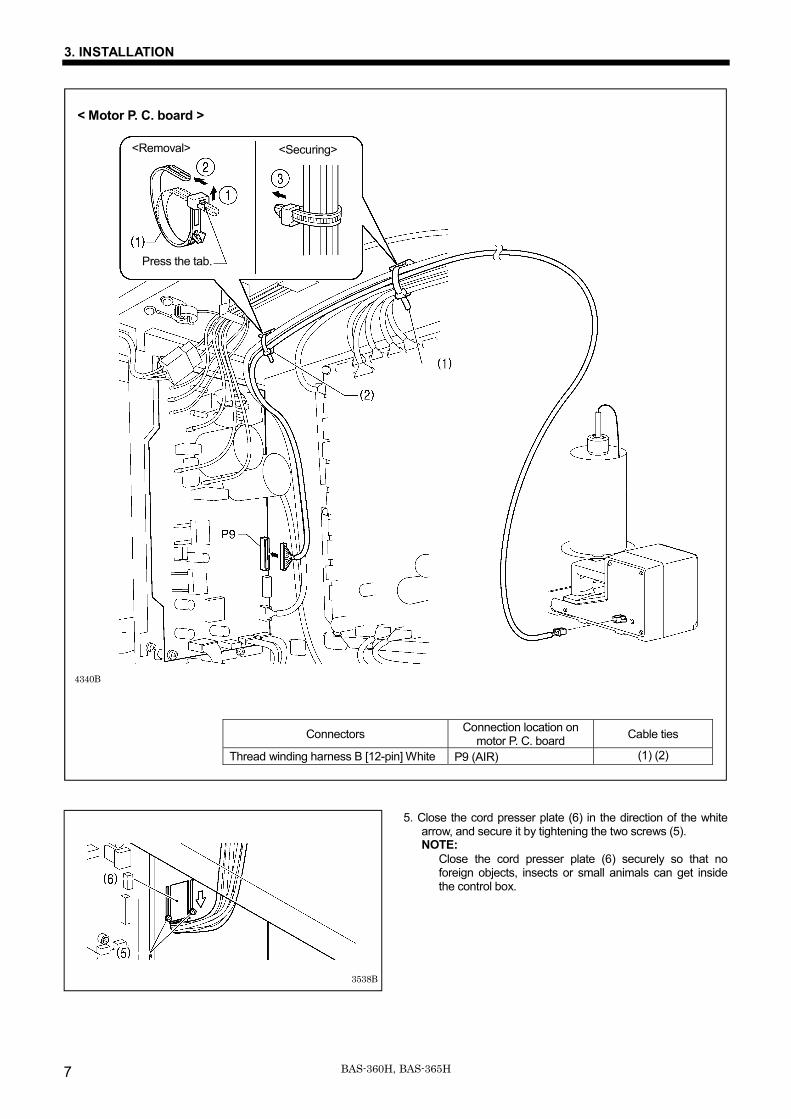
Connectors Connection location on motor P. C. board Cable ties
Thread winding harness B [12-pin] White P9 (AIR) (1) (2)
5. Close the cord presser plate (6) in the direction of the white arrow, and secure it by tightening the two screws (5). NOTE:
Close the cord presser plate (6) securely so that no foreign objects, insects or small animals can get inside the control box.
< Motor P. C. board >
4340B
<Removal>
Press the tab.
<Securing>
3538B

3. INSTALLATION
8BAS-360H, BAS-365H
3-5. Connecting the ground wire
CAUTION Be sure to connect the ground. If the ground connection is not secure, you run a high risk of receiving a serious electric shock, and problems with correct operation may also occur.
(1) Ground wire from LCD panel harness
・ After connecting the ground wire, tighten the control box cover with the eight screws. Check that the cords are not clamped by the cover at this time.
NOTE: Make sure that the ground connections are secure in order to ensure safety.
4116B

3. INSTALLATION
9 BAS-360H, BAS-365H
3-6. Connecting the power cord
CAUTION Be sure to connect the ground. If the ground connection is not secure, you run a high risk of receiving a serious electric shock, and problems with correct operation may also occur.
Connect cords that match the voltage specifications.
< EU specifications> 1. Attach an appropriate switch and cable
to the power cord (1). (The green and yellow wire is the ground wire.)
2. Insert the power plug into a properly-grounded electrical outlet.
NOTE: Do not use extension cords, otherwise machine operation problems may result.
Connect cords that match the voltage specifications.
<200 V system > 1. Attach an appropriate plug to the
power cord (1). (The green and yellow wire is the ground wire.)
2. Insert the power plug into a properly-grounded electrical outlet.
NOTE: Do not use extension cords, otherwise machine operation problems may result.
4345B
4344B
Green and yellow wire (ground wire)
4117B
Green and yellow wire (ground wire)
Green and yellow wire (ground wire)

3. INSTALLATION
10BAS-360H, BAS-365H
<400 V system > (1) Power switch (2) Wood screws [2 pcs.] (3) Cord clamps [4 pcs.] (4) 3-pin power supply connector (5) Power cord
1. Remove the power switch (1)
which is already installed. 2. Remove the 3-pin power supply
connector (4) from the cord clamp (3).
3. Disconnect the 3-pin power supply connector (4) inside the control box.
(1) Power switch (2) Wood screws [2 pcs.] (3) Cord clamps [4 pcs.] (4) 3-pin power supply connector (5) Power cord (6) Transformer box (7) Mounting plate (8) Screws [with washer] [4 pcs.]
1. Attach an appropriate plug to the power cord (5). (The green and yellow wire is the ground wire.)
2. Insert the power plug into a properly-grounded electrical outlet.
NOTE: ・ If the ground connection is not
secure, electric shocks, operating errors or damage to electronic components such as P.C. boards may occur.
・ Do not use extension cords, otherwise machine operation problems may result.
3. Use the eight screws to tighten the
cover of the control box. Check that none of the cords are being clamped by the cover at this time.
4346B
4347B
Green and yellow wire (ground wire)
Green and yellow wire (ground wire)

3. INSTALLATION
11 BAS-360H, BAS-365H
3-7. Lubrication
CAUTION Do not connect the power cord plug until installation is complete. If this is not done, the sewing machine may operate if a switch is pressed by mistake, which could result in serious injury.Be sure to wear protective goggles and gloves when handling the lubricating oil and grease, so that they do not get into your eyes or onto your skin. If the oil and grease get into your eyes or onto your skin, inflammation can result. Furthermore, do not drink or eat the lubricating oil or grease. They may cause diarrhea or vomiting. Keep the oil out of the reach of children.
・ The sewing machine should always be lubricated and the oil supply replenished before it is used for the first time, and also after long periods of non-use.
・ Use only the lubricating oil <JXTG Energy Sewing Lube 10N; VG10> specified by Brother. * If this type of lubricating oil is difficult to obtain, the
recommended oil to use is <Exxon Mobil Essotex SM10; VG10>.
1. Remove the oil feeding pocket cover (1) and add oil. NOTE:
Be sure to add more oil when the oil level drops down to about one-third full in the oil gauge window (2).If the oil drops below the one-third full level in the oil gauge window (2), there is the danger that the sewing machine may seize during operation.
2. Pour oil in through the two holes of the shuttle race base assembly so that the felt (3) is lightly moistened. If it is difficult to add oil, you can also remove the rubber cap (4) and pour in the oil through the hole. NOTE:
・ The two pieces of felt (3) should normally project by 0 to 0.5 mm from the hook race. Be careful not to push in the felt (3) when lubricating.
・ If there is no more oil on the felt (3) of the shuttle race base assembly, problems with sewing may result.
3. If using the needle cooler (5), fill it with silicon oil. (Refer to "4-4. Threading the upper thread" for details on using the needle cooler (5).)
4118B4119B4120B

4. PREPARATION BEFORE SEWING
12BAS-360H, BAS-365H
4. PREPARATION BEFORE SEWING 4-1. Installing the needle
CAUTION Turn off the power switch before installing the needle. If this is not done, the sewing machine may operate if a switch is pressed by mistake, which could result in serious injury.
1. Loosen the set screw (1). 2. Insert the needle (2) in a straight line as far as it will go,
making sure that the long groove on the needle is facing toward the sewing machine, and then securely tighten the screw (1).
4-2. Hand start switch operation method When the right switch (1) is pressed, the intermittent presser foot (2) and the work clamp (3) will drop, and when the left switch (4) is pressed, they will rise. When the left switch (4) and right switch (1) are pressed together while the intermittent presser foot (2) and the work clamp (3) are lowered, the sewing machine will start.
NOTE: Use a work clamp and feed plate which are suitable for the sewing area. If a work clamp or feed plate which is unsuitable for the sewing area is used, the needle may break and injury may occur.
4-3. Threading the thread 1. Set the thread spool in place, and then place the thread
spool presser (1) against the top part of the thread spool to hold it in place.
2. Pass the thread through the top of the thread spool shaft (2).
4341B
4122B
4121B

4. PREPARATION BEFORE SEWING
13 BAS-360H, BAS-365H
4-4. Threading the upper thread Thread the upper thread correctly as shown in the illustration below. * When using threading mode for threading, the thread can be threaded more easily.
(Refer to "Threading mode" on the next page.) ・ Turn the machine pulley (1) and raise the thread take-up (2) to its highest position before threading the upper thread.
(This will make threading easier and it will prevent the thread from coming out at the sewing start.) ・ When threading the thread through the needle, allow a distance of approximately 42 mm between the needle hole and the
end of the thread. If it is too long, the thread may become tangled, and if it is too short, the thread may pull out at the sewing start.
・ If you would like to adjust the sensitivity of the thread breakage sensor, refer to "7-6. Adjusting the sensitivity of the thread breakage sensor”.
[If using cotton thread or spun thread]
4123B
4124B
[If using synthetic thread]
4125B
Needle cooler
Thread the upper thread
Needle cooler

4. PREPARATION BEFORE SEWING
14BAS-360H, BAS-365H
<Threading mode> Threading mode is safe because the sewing machine will not start even when the hand start switch is depressed.
1
Turn on the power.
2
Touch the Thread key on the screen.
・ The feed plate lock cylinder will lock. ・ The tension discs will open.
3 Threading the thread.
4 Ending threading mode The display will return to the previous screen.
Touch the OK key on the screen.
・ The sewing machine will return to the status that it was at
before switching to threading mode.
4126B

4. PREPARATION BEFORE SEWING
15 BAS-360H, BAS-365H
4-5. Winding the lower thread
CAUTION
Do not touch any of the moving parts or press any objects against the sewing machine while winding the thread. If this is not observed, it may result in serious injury or damage to the devices.
1. Place the thread on top of the thread spool bracket (1), and then place the thread spool presser (2) against the top part to hold the thread in place.
2. Place the bobbin onto the thread spool shaft (3).
3. Pass the thread through the thread spool shaft (4) from the top to the bottom.
4. Thread the thread as shown in the illustration, and then turn the bobbin several times in the direction of ① to wind the thread.
5. When the bobbin presser arm (5) is pushed in the direction of ②, the thread will start being wound.
6. When winding is finished, the bobbin presser arm (5) will automatically release the bobbin, and winding will stop.
[NOTE:] ・ When the circuit protector (6) operates, the thread
winding motor will not work. Let the mechanism stand for one minute or more to allow it to cool down, and then press the circuit protector. (If the mechanism is not allowed to cool down, nothing will happen when the circuit protector is pressed.)
・ If the manual winding tension is stronger than necessary, it may cause problems with sewing.
When using the bobbin winder by itself
・ Peel off the sticker, and then insert the AC adapter in
the direction of the arrow.
4342B
4127B

4. PREPARATION BEFORE SEWING
16BAS-360H, BAS-365H
WARNING
Be sure to use an AC adapter that complies with the safety standards in the country of use. Otherwise, it may cause fire or electric shocks or problems with correct operation.
Purchase an AC adaptor conforming to the specifications below.
OUTPUT: 24 V DC, 1A
Polarity:
3670B
3671B
OUTPUT DC24V 1A
Φ2.1mm
Φ5.5mm
1.5mm
9.5mm

4. PREPARATION BEFORE SEWING
17 BAS-360H, BAS-365H
Adjusting the bobbin winding amount Loosen the screw (7) and move the bobbin presser (8). If the thread winds onto the bobbin unevenly Loosen the set screw (9) and move the bobbin winder tension assembly (10) forward and back to adjust. * For case A, move the bobbin winder tension assembly
(10) in the direction of a, and for case B, move it in the direction of b.
4-6. Installing the bobbin case
CAUTION Turn off the power switch before installing the bobbin case. If this is not done, the sewing machine may operate if a switch is pressed by mistake, which could result in serious injury.
1. Pull the shuttle race cover (1) downward to open it. 2. While holding the bobbin so that the thread winds to the right, insert the bobbin into the bobbin case. 3. Pass the thread through the slot (2) and pull it out from the thread hole (3). 4. Check that the bobbin turns in the direction of the arrow when the thread is pulled. 5. Pass the thread through the lever thread hole (4), and then pull out approximately 30 mm of thread. 6. Hold the latch on the bobbin case and insert the bobbin case into the rotary hook.
4130B
2534Q
2535Q
30mm
4128B
4129B
Less thread
More thread
Case B
Case A

4. PREPARATION BEFORE SEWING
18BAS-360H, BAS-365H
4-7. Thread tension [Thread tension reference]
*1 This is the tension value when the pretension is 0.2 N. 4-7-1. Lower thread tension
Adjust the thread tension to the weakest possible tension by turning the thread tension nut (1) until the bobbin case will not drop by its own weight while the thread end coming out of the bobbin case is held.
Upper thread #20 or similar
Lower thread #20 or similar
Upper thread tension (N) [Tension value]
1.4 − 1.8 [140 - 180]*1
Lower thread tension (N) 0.3 − 0.4
Pre-tension (N) 0.2 − 0.4
Needle DP x 17 #19
2536Q
StrongerWeaker

4. PREPARATION BEFORE SEWING
19 BAS-360H, BAS-365H
4-7-2. Upper thread tension
Use the digital tension to adjust the tension as appropriate for the material being sewn. (Refer to “Setting the tension value” below.) Turn the tension nut (1) (sub-tension) to adjust so that the upper thread trailing length is about 42 mm.
Setting the tension value Touch the △ and ▽ keys (2) on the sewing operation screen to increase or decrease the Tension value.
[Sewing operation screen]
(2)
4131B
Weaker Stronger

4. PREPARATION BEFORE SEWING
20BAS-360H, BAS-365H
4-8. Starting up Before turning on the power, check that the needle bar is at the needle up stop position. Turn the pulley (1) in the direction of the arrow until the ridge at the bottom of the thread take-up (2) is aligned with the index mark. * If they are not aligned, the thread take-up lever (2) will move
automatically during sewing and the upper thread may pull out from the needle after threading.
Turn on the power. If a program has been registered, the program number and a preview of the sewing pattern will be displayed. No programs are registered at the time of shipment from the factory, and so "---" is displayed as the program number (No.). For details on the sewing data reading method, refer to "3. USING STORAGE MEDIA" in the "LCD Panel/Operation Panel" Instruction Manual".
4124B
4133B
<When a program is registered>
<When no program is registered>
Aligned

5. SEWING
21 BAS-360H, BAS-365H
5. SEWING WARNING
Do not allow any liquids to get onto this sewing machine, otherwise fire, electric shocks or operating problems may occur. If any liquid gets inside the sewing machine (machine head or control box), immediately turn off the power and disconnect the power plug from the electrical outlet, and then contact the place of purchase or a qualified technician.
CAUTION Turn off the power switch at the following times. If this is not done, the sewing machine may operate if a switch is pressed by mistake, which could result in serious injury. When replacing the bobbin and needle When not using the machine and when leaving the machine unattended Do not touch any of the moving parts or press any objects against the machine while sewing, as this may result in personal injury or damage to the machine.
5-1. Sewing
1. Turn on the power. 2. Touch the △ or ▽ key to select the number for the
program to be sewn. * For details on reading sewing data from SD cards and
USB memory devices, refer to "3-4. Importing items of sewing data separately" in the "LCD panel/Operation pane" Instruction Manual.
3. When the left switch (1) and the right switch (2) are pressed together, home position detection will start. When home position detection is complete, the feed plate lock cylinder will automatically unlock, and the work clamp (3) will rise.
4. Place the material onto the feed plate (4), and set the feed plate (4) to the feed plate lock position. When this is done, the feed plate (4) will lock and the work clamp (3) will drop.
5. When the left switch (1) and the right switch (2) are pressed together, sewing will start.
6. When sewing is complete, the thread will be trimmed, and then the work clamp (3) will rise and the feed plate (4) will unlock.
Use a work clamp (3) which will hold the material securely so that it does not slip. If the material slips when using the standard work clamp (3) and feed plate (4), process the work clamp (3) and feed plate (4) so that the material does not slip.
4134B
4134B

5. SEWING
22BAS-360H, BAS-365H
5-2. Using the STOP switch If you press the emergency stop switch (1) to during actual sewing, an error dialog box will be displayed and the sewing machine will immediately stop.
<Clearing> 1. Touch the Reset key (2).
・ The thread will be trimmed, and then the error dialog box on the screen will disappear and the buzzer will stop.
2. A dialog box asking you to confirm if you want to continue sewing will be displayed.
<Continuing sewing from a stopping point> If the thread breaks or the lower thread runs out during sewing, you can then continue sewing from the point where the thread broke or ran out.
1
Touch "Yes" (3) to return to the resewing standby screen.
2
Touch the keys (5) and (6) on the screen to return to the position where sewing is to be resumed.
When you touch the key (5), the feed will move backward
by 1 stitch, and when you touch the key (6), the feed will move forward by 1 stitch.
3 Press the left switch (1) and the right switch (2) together.
<Returning to the sewing start position without continuing sewing> If you do not wish to continue sewing, touch "No" (4). ・After home position detection is carried out, the mechanism will return to the sewing start position.
4136B
(3) (4)
(5) (6)
(2)
4135B
5. SEWING
23 BAS-360H, BAS-365H
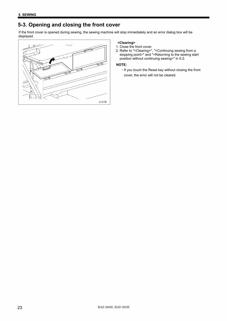
5-3. Opening and closing the front cover If the front cover is opened during sewing, the sewing machine will stop immediately and an error dialog box will be displayed.
<Clearing> 1. Close the front cover. 2. Refer to "<Clearing>", "<Continuing sewing from a
stopping point>" and "<Returning to the sewing start position without continuing sewing>" in 5-2.
NOTE: ・If you touch the Reset key without closing the front
cover, the error will not be cleared.
4137B

6. CLEANING
24BAS-360H, BAS-365H
6. CLEANING CAUTION
Turn off the power switch before carrying out cleaning. If this is not done, the sewing machine may operate if a switch is pressed by mistake, which could result in serious injury. Be sure to wear protective goggles and gloves when handling the lubricating oil and grease, so that they do not get into your eyes or onto your skin. If the oil and grease get into your eyes or onto your skin, inflammation can result. Furthermore, do not drink or eat the lubricating oil or grease. They may cause diarrhea or vomiting. Keep the oil out of the reach of children.
6-1. Cleaning the rotary hook 1. Pull the shuttle race cover downward to open it, and then
remove the bobbin case. * It may be easier to clean the rotary hook if it is done in
maintenance mode. Refer to "7-1. Preparing the rotary hook for maintenance".
2. Open the setting claw (1) in the direction indicated by the arrow, and then remove the shuttle race base (2) and the shuttle hook (3).
3. Clean all the dust and lint from around the driver (4), the top of the rotary hook thread guide and the shuttle race.
6-2. Draining the oil
1. Remove and empty the oiler (1) whenever it is full. 2. After emptying oiler (1), screw it back into its original
position.
4139B
4138B

6. CLEANING
25 BAS-360H, BAS-365H
6-3. Checking the regulator
1. If water collects in the bottle of the regulator (1), turn the drain cock (2) in the direction of the arrow to drain the water.
2. After draining the water, tighten the drain cock (2).
6-4. Cleaning the control box air inlet ports
Use a vacuum cleaner to clean the filter in the air inlet ports (2) of the control box (1) at least once a month.
6-5. Cleaning the eye guard
Wipe the eye guard clean with a soft cloth. NOTE:
Do not use solvents such as kerosene or thinner to clean the eye guard.
6-6. Checking the needle
Always check that the tip of the needle is not broken and also that the needle is not bent before starting sewing.
6-7. Lubrication Lubricate the sewing machine while referring to "3-7. Lubrication".
4143B
4140B
4141B
4142B

6. CLEANING
26BAS-360H, BAS-365H
6-8. Applying grease If the grease-up warnings [E100] or [E101] appear, apply grease to the needle bar bush. * If the warnings [E104] or [E105] for adding both grease and oil appear, add both grease and oil while also referring to "6-9.
Adding gear box lubricating oil".
<Applying grease> Use Brother-specified “Grease unit (SB1275-201)”. Ask the place of purchase for details on obtaining these items. 1. Using the tube
2. Removing the needle cooler device and eye guard
Loosen the two bolts (1), remove the needle cooler device (2), and then loosen the bolt (3) and the screw (4) and remove the eye guard assembly (5).
4087M
4380B
6. CLEANING
27 BAS-360H, BAS-365H
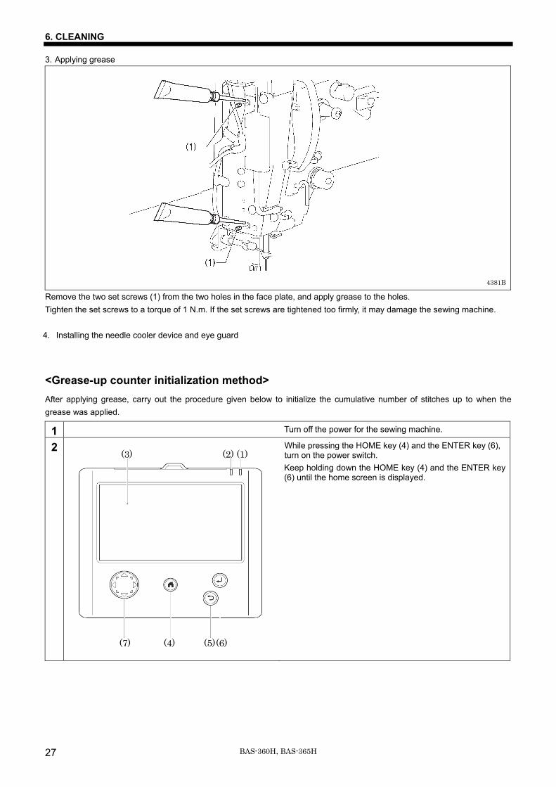
3. Applying grease
Remove the two set screws (1) from the two holes in the face plate, and apply grease to the holes. Tighten the set screws to a torque of 1 N.m. If the set screws are tightened too firmly, it may damage the sewing machine. 4. Installing the needle cooler device and eye guard
<Grease-up counter initialization method> After applying grease, carry out the procedure given below to initialize the cumulative number of stitches up to when the grease was applied.
1 Turn off the power for the sewing machine.
2
While pressing the HOME key (4) and the ENTER key (6), turn on the power switch. Keep holding down the HOME key (4) and the ENTER key (6) until the home screen is displayed.
4381B
(3) (2) (1)
(7) (4) (5) (6)

6. CLEANING
28BAS-360H, BAS-365H
3
When the screen shown at left appears, release the keys.
4
Touch Settings → Sewing Machine Adjustment → Grease up.
5
If you touch OK in the screen shown at left, the grease up counter will be initialized.
6 After the initialization is complete, turn off the power.

6. CLEANING
29 BAS-360H, BAS-365H
6-9. Adding gearbox lubricating oil If the lubricating oil warnings [E102] or [E103] appear, add lubricating oil to the gearbox of the rotary hook base. * If the warnings [E104] or [E105] for adding both grease and oil appear, add both grease and oil while also referring to "6-8.
Applying grease".
<Adding lubricating oil> Use only the lubricating oil <JXTG Energy Sewing Lube 10N; VG10> specified by Brother. Ask the place of purchase for details on obtaining this item.
1. Push the tip of the oiler against the oil feeding pocket at the left side of the rotary hook base to add oil. When the oil level is in between the two reference lines in the oil gauge window below the oil feeding pocket, the correct amount of oil has been added. NOTE: ・ If the oil level is below the lower reference line,
operating problems such as motor seizure may result.
・Do not allow the oil level to go past the top reference line. Oil leaks may occur during sewing machine operation.
2. After adding oil, carry out the initialization operation.
NOTE: If you continue to use the sewing machine after carrying out the initialization procedure but without adding oil, problems with the sewing machine may result.

6. CLEANING
30BAS-360H, BAS-365H
<Oil lubrication counter initialization method> After adding oil, carry out the procedure given below to initialize the cumulative number of stitches up to when the oil was added.
1 Turn off the power for the sewing machine.
2
While pressing the HOME key (4) and the ENTER key (6), turn on the power switch. Keep holding down the HOME key (4) and the ENTER key (6) until the home screen is displayed.
3
When the screen shown at left appears, release the keys.
4
Touch Settings → Sewing Machine Adjustment → Oil lubrication.
(3) (2) (1)
(7) (4) (5) (6)

6. CLEANING
31 BAS-360H, BAS-365H
5
If you touch OK in the screen shown at left, the oil lubrication counter will be initialized.
6 After the initialization is complete, turn off the power.

7. STANDARD ADJUSTMENTS
32BAS-360H, BAS-365H
7. STANDARD ADJUSTMENTS CAUTION
Maintenance and inspection of the sewing machine should only be carried out by a qualified technician. Ask your Brother dealer or a qualified electrician to carry out any maintenance and inspection of the electrical system. Turn off the power switch and disconnect the power cord before carrying out the following operations. If this is not done, the sewing machine may operate if a switch is pressed by mistake, which could result in serious injury. ・ Inspection, adjustment and maintenance ・ Replacing consumable parts such as the rotary
hook Disconnect the air hoses from the air supply and wait for the needle on the pressure gauge to drop to "0" before carrying out inspection, adjustment and repair of any parts which use the pneumatic equipment.
If the power switch and air need to be left on when carrying out some adjustment, be extremely careful to observe all safety precautions. Be sure to wear protective goggles and gloves when handling the lubricating oil and grease, so that they do not get into your eyes or onto your skin. If the oil and grease get into your eyes or onto your skin, inflammation can result. Furthermore, do not drink or eat the lubricating oil or grease. They may cause diarrhea or vomiting. Keep the oil out of the reach of children. If any safety devices have been removed, be absolutely sure to re-install them to their original positions and check that they operate correctly before using the machine.
7-1. Preparing the rotary hook for maintenance
When carrying out adjustments in the area around the rotary hook, first switch the sewing machine to maintenance mode, and then move the machine head (1) to the left edge. (For details on the method of operation, refer to the LCD panel instruction manual.) Next, remove the five screws (2), and then remove the maintenance cover (3). Next, remove the two screws (4) and the two flat screws (5), and then remove the needle plate (7). Applicable tasks: Adjusting the needle and rotary hook timing
Adjusting the driver (needle guard) position Adjusting the clearance between the needle and rotary hook tip Adjusting the shuttle race thread guide Replacing the movable knife and fixed knife
4145B
4144B

7. STANDARD ADJUSTMENTS
33 BAS-360H, BAS-365H
7-2. Removing and installing the feed plate 1. When the left switch (1) is pressed, the feed plate (2) will unlock so that it can then be removed.
Pull the feed plate (2) directly forward to remove it. 2.When installing the feed plate (2), if the two feed plate lock plates (3) are fitted into the gaps in the two cylinder mounting
blocks (4), the two lock cylinders (5) will automatically operate and the feed plate (2) will be locked.
7-3. Thread take-up spring Thread take-up spring height
(mm) 6 - 10
Thread take-up spring tension (N)
1.0 - 1.4
<Thread take-up spring height> Loosen the set screw (1) and turn the adjuster to adjust. <Thread take-up spring tension> 1. Press the upper thread slightly above the tension bracket
with a finger to stop the thread spooling out. 2. Pull the upper thread downward so that the thread take-up
spring (3) is extended to the same height as the base of the thread guide arm (4), and then measure the tension of the thread take-up spring (3).
3. Use a screwdriver to turn the tension stud (5) in order to adjust the tension of the thread take-up spring (3).
NOTE: If the thread tension spring (3) is not adjusted correctly, the upper thread trailing length will be uneven after thread trimming.
Weaker
Stronger
4148B
Lower Higher
4147B
4146B

7. STANDARD ADJUSTMENTS
34BAS-360H, BAS-365H
7-4. Arm thread guide R The standard position of arm thread guide R (1) is when the screw (2) is aligned with the index mark. Loosen the screw (2) and move the arm thread guide R (1) to adjust.
・ When sewing heavy-weight material, move the arm thread guide R (1) to the left. (The thread take-up amount will become greater.)
・ When sewing light-weight material, move the arm thread guide R (1) to the right. (The thread take-up amount will become smaller.
7-5. Adjusting the needle bar height
Turn the pulley in the direction of the arrow to move the needle bar to the lowest position. Then remove the rubber plug (2), loosen the screw (3) and then move the needle bar up or down to adjust so that the second reference line from the bottom of the needle bar (reference line A) is aligned with the lower edge of the needle bar bush (1).
4149B
3497B
More thread Less thread
Index mark
4150B

7. STANDARD ADJUSTMENTS
35 BAS-360H, BAS-365H
7-6. Adjusting the sensitivity of the thread breakage sensor 1. Thread the upper thread and pull the upper thread straight. 2. When the red light from the fiber strikes the thread, check
that the incoming light amount is smaller than the threshold value for the fiber amplifier (2). If the incoming light amount is greater than the threshold value, increase the threshold value.
Press the (setting increase) or (setting decrease) key to change the threshold value. (Keep pressing the key to accelerate the change speed.)
3. Pull the thread straight once more, and if the incoming light amount is smaller than the threshold value, adjustment of the sensor sensitivity is complete.
NOTE:
Thread breakages may be difficult to detect depending on the thickness of the thread and the type of material being sewn. In such cases, adjust the threshold value, or change the number of stitches for judgment of an upper thread breakage. * Contact the place of purchase for information on the
method of changing the number of stitches for judgment of an upper thread breakage.
4191B
Setting value UP keySetting value DOWN key
Threshold value Incoming light amount

7. STANDARD ADJUSTMENTS
36BAS-360H, BAS-365H
7-7. Adjusting the needle and rotary hook timing
1. Turn the pulley (1) in the direction of the arrow to raise the needle bar from the lowest position until the lowest reference line on the needle bar (reference line B) is aligned with the lower edge of the needle bar bush (2).
2. Loosen the bolt (3). 3. Move the driver (4) sideways so that the tip of the rotary hook is aligned with the middle of the needle, and then tighten the
bolt (3).
7-8. Adjusting the driver (needle guard) position Turn the pulley (1) in the direction of the arrow to align the tip of the rotary hook with the center of the needle, and then loosen the screw (3) and turn the adjusting stud (4) to adjust so that the driver (2) is touching the needle.
NOTE: If the driver (2) crosses the needle more than necessary, it will cause problems with the thread tension. Furthermore, if it does not cross the needle at all, the tip of the rotary hook will interfere with the needle and skipped stitches may occur.
4151B 4152B
Center of the needle
Tip
4124B 0135Q
Center of the needle
Tip
0135Q 3515B 4155B 4154B

7. STANDARD ADJUSTMENTS
37 BAS-360H, BAS-365H
7-9. Adjusting the clearance between the needle and rotary hook tip Turn the pulley in the direction of the arrow to align the tip of the rotary hook with the center of the needle, and then loosen the set screw (1) and turn the adjusting stud (2) to adjust so that the clearance between the needle and the tip of the rotary hook is 0.03 to 0.08 mm.
7-10. Adjusting the shuttle race thread guide
Install the shuttle race thread guide (1) by pushing it in the direction of the arrow so that the needle groove is aligned with the center of the needle plate hole. NOTE:
If the shuttle race thread guide (1) is in the wrong position, thread breakages, soiled thread or tangling of the thread may occur. The position of the shuttle race thread guide (1) is adjusted at the time of shipment from the factory. It should not be changed if possible.
0.01 - 0.08mm
4157B
0138Q 4156B

7. STANDARD ADJUSTMENTS
38BAS-360H, BAS-365H
7-11. Replacing the movable and fixed knives 1. Remove the movable knife (1) and the fixed knife (2).
2. Install the new fixed knife (2) in the positions shown in the illustration. 3. Apply grease to the outside of the collar (3) and to the shoulder screw (4), and then install the new movable knife (1)
together with the thrust washer (5) and movable knife spacer (6). 4. Check that the movable knife (1) and fixed knife (2) cut the thread cleanly. Replace the movable knife spacer with accessory
spacers (10) (t=0.2, 0.3, 0.4) so that the knives trim the thread accurately. * If the knife pressure is too weak and the thread is not completely cut, use a thinner movable knife spacer. * If the knife pressure is too strong and the movable knife (1) turns stiffly, use a thicker movable knife spacer.
5. Apply grease to the pin (7) of the movable knife, insert it into the hole in the movable knife connecting plate (8), and then install the needle plate (9).
6. Check that the needle is aligned with the center of the needle hole.
4193B 4194B
4192B

7. STANDARD ADJUSTMENTS
39 BAS-360H, BAS-365H
7-12. Adjusting the thread wiper 1. Loosen the two screws (3) and move the thread wiper shaft bracket (4) to the left or right to adjust so that the thread wiper
(2) is 15 mm to the left of the needle center when the cylinder (1) operates until it is pulled out to its full stroke. 2. Loosen the screw (5) and adjust the position of the thread wiper (2) so that the distance from the thread wiper to the tip of
the needle is approximately 2 mm and the tip of the thread wiper (2) is approximately 3 mm from the center of the needle when the thread wiper (2) passes below the needle during operation.
NOTE: Check that the thread wiper (2) does not touch the finger guard (6).
7-13. Intermittent presser foot installation position Install the intermittent presser foot (1) with the screw (2) so that the distance from the bottom of the intermittent presser foot (1) to the top of the needle plate is 22 mm when the sewing machine is stopped and the intermittent presser foot (1) is raised
4158B 4160B
Approx. 3mm
Approx. 2mm
4161B
4159B

7. STANDARD ADJUSTMENTS
40BAS-360H, BAS-365H
7-14. Adjusting the air pressure Lift up the handle (2) of the regulator (1) and then turn it to adjust the air pressure to 0.5 MPa. After adjustment is complete, push the handle (2) downward to lock it.
7-15. Adjusting the speed controller You can adjust the lifting and lowering speeds for the work clamp using the knobs on the valves.
・ When the knob 1 is tightened, the lifting speed becomes slower. When it is loosened, the lifting speed becomes faster.
・ When the knob 2 is tightened, the lowering speed becomes slower. When it is loosened, the lowering speed becomes faster.
Reference adjustments Knob 1 Fully tighten Knob 2 Fully tighten and then loosen by 8 turns
You can operate the work clamp when the power is turned off by pressing the manual button (1).
4162B
Work clamp
Knob 1
Knob 2
4243B
4163B

7. STANDARD ADJUSTMENTS
41 BAS-360H, BAS-365H
7-16. If processing the feed plate to a shape that matches the sewing pattern
Process the work clamp and feed plate which match the sewing pattern, while referring to the processing diagram below. * Values in ( ) are the recommended sizes when sewing using the maximum area (BAS-360H: 500x400 mm, BAS-365H:
700x400 mm)
BAS-360H
BAS-365H
<Feed plate processing diagram> Recommended thickness 1.5 mm
4165B
4167B
[mm]
[mm]
<Feed plate processing diagram> Recommended thickness 1.5 mm
Center of sewing area
Center of sewing area

8. LIST OF ERROR CODES
BAS-360H, BAS-365H 42
8. LIST OF ERROR CODES DANGER
Wait at least 5 minutes after turning off the power switch and disconnecting the power cord from the wall outlet before opening the control box cover. Touching areas where high voltages are present can result in severe injury.
If a malfunction occurs with the sewing machine, a buzzer will sound and an error code will appear on the screen. Follow the remedy procedure to eliminate the cause of the problem.
Switch-related errors Code Cause of error and remedy
E010 The STOP switch was pressed. Press the Reset key to clear the error.
E011 The STOP switch was pressed. Press the Reset key to clear the error.
You can press the keys on the LCD panel to move the feed in order to continue sewing.
E012 The STOP switch was pressed. Press the Reset key to clear the error, and then the start switch or both the left and right switches to move the feed mechanism to the home position.
E015 The STOP switch was still being pressed when the power was turned on, or there is a problem with the stop switch connection. Turn off the power, and then check that the connector P40, P41, P42, P43 on the main board is properly inserted.
E016 Problem with the STOP switch connection. Turn off the power, and then check that the connector P40, P41, P42, P43 on the main board is properly inserted.
E020 The start switch was pressed or the left and right switches were pressed at the same time without the work clamp being lowered. First lower the work clamp.
E021 The feed plate is not loaded properly. Make sure the position of the feed plate and try again.
E025 The right switch was being depressed (For 2, 3 pedal, start switch was being depressed) when power was turned on. Release the pedal or switch.
E035 Work clamp switch or left switch was being depressed when power was turned on. Release the pedal or switch.
E054 The front cover was open when power was turned on. Close the front cover.
E064 Touch panel was being touched when power was turned on. Release the touch panel.
E065 A key on the LCD panel was still being pressed when the power was turned on, or key is faulty. Release the key.
E070 Front cover was opened. After front cover closed, press the Reset key to clear the error.
E071 Front cover was opened. After front cover closed, press the Reset key to clear the error. You can press the keys on the LCD panel to move the feed in order to continue sewing.
E072 Front cover was opened. After front cover closed, press the Reset key to clear the error, then press both left and right switch at the same time, and conduct the home position detection.

8. LIST OF ERROR CODES
BAS-360H, BAS-365H 43
Motor-related errors Code Cause of error and remedy
E100 It is time for grease up. Apply grease after turning off the power of the sewing machine. After that, operate the prescribed reset procedure. For details, refer to "6-8. Applying grease".
E101 Grease up period has been approached. Apply grease after turning off the power of the sewing machine. After that, operate the prescribed reset procedure. To continue sewing without grease up, press Reset key. For details, refer to "6-8. Applying grease".
E102 It is time for oil lubrication. Apply the lubricating oil after turning off the power of the sewing machine. After that, operate the prescribed reset procedure. For details, refer to "6-9. Adding gearbox lubricating oil".
E103 Oil lubrication period has been approached. Apply the lubricating oil after turning off the power of the sewing machine. After that, operate the prescribed reset procedure. To continue sewing without oil lubrication, press Reset key. For details, refer to "6-9. Adding gearbox lubricating oil".
E104 It is time for oil lubrication and grease up. Apply grease and the lubricating oil after turning off the power of the sewing machine. After that, operate the prescribed reset procedure. For details, refer to "6-8. Applying grease" and "6-9. Adding gearbox lubricating oil".
E105
Both grease up period and oil lubrication period have been approached. Apply grease and the lubricating oil after turning off the power of the sewing machine. After that, operate the prescribed reset procedure. To continue sewing without grease up or lubrication, press Reset key. For details, refer to "6-8. Applying grease" and "6-9. Adding gearbox lubricating oil".
E110 The needle bar is not stopped in the needle up stop position. Turn the pulley until the point where the error display disappears.
E111 Upper shaft did not stop at the needle up stop position when the sewing machine stopped. Turn off the power, and then check that connectors P11 and P1 on the motor board and connector P6 on the main board are properly inserted.
E121 Thread trimming was not completed. Turn off the power, and then check if the cutting edges of the fixed knife and movable knife are damaged or worn.
E130 Upper shaft motor stopped due to a problem, or synchronizer is faulty. Turn off the power, and then turn the pulley and check if the sewing machine has locked up. Check that connectors P11 and P1 on the motor board, connector P6 on the main board and the 4-pin connector of the upper shaft motor on the motor board
E131 Synchronizer is not connected correctly. Turn off the power, and then check that connector P11 on the motor board is properly connected.
E132 Problem detected with upper shaft motor operation. Turn off the power, and then check that connectors P11 and P1 on the motor board, connector P6 on the main board and the 4-pin connector of the upper shaft motor on the motor board are properly inserted.
E133 Upper shaft motor stopping position is incorrect. Turn off the power, and then check that connectors P11 and P1 on the motor board, connector P6 on the main board and the 4-pin connector of the upper shaft motor on the motor board are properly inserted.
E150 Upper shaft motor is overheating, or temperature sensor is faulty. Turn off the power, and then check the upper shaft motor. (When sewing data with a small number of stitches (15 stitches or less) is sewn repeatedly (short cycle operation), the upper shaft motor may overheat and the “E150” error code may be generated.)

8. LIST OF ERROR CODES
BAS-360H, BAS-365H 44
Feed mechanism-related errors Code Cause of error and remedy
E200 X-feed motor home position cannot be detected. Problem with X-feed motor or poor X home position sensor connection. Turn off the power, and then check that connectors P17, P21 and P8 on the main board are properly connected.
E201 X-feed motor stopped due to a problem. Turn off the power, and then check if there are any problems in the X-feed direction. Turn off the power, and then check that connectors P17 and P21 on the main board are properly connected.
E204 X-feed motor stopped due to a problem during sewing. Turn off the power, and then check if there are any problems in the X-feed direction. Turn off the power, and then check that connectors P17 and P21 on the main board are properly connected.
E205 X-feed motor stopped due to a problem while moving to the sewing start position. Turn off the power, and then check if there are any problems in the X-feed direction. Turn off the power, and then check that connectors P17 and P21 on the main board are properly connected.
E206 X-feed motor stopped due to a problem during test feeding. Turn off the power, and then check if there are any problems in the X-feed direction. Turn off the power, and then check that connectors P17 and P21 on the main board are properly connected.
E210 Y-feed motor home position cannot be detected. Problem with Y-feed motor or poor Y home position sensor connection. Turn off the power, and then check that connectors P18, P22 and P8 on the main board are properly connected.
E211 Y-feed motor stopped due to a problem. Turn off the power, and then check if there are any problems in the Y-feed direction. Turn off the power, and then check that connectors P18 and P22 on the main board are properly connected.
E214 Y-feed motor stopped due to a problem during sewing. Turn off the power, and then check if there are any problems in the Y-feed direction. Turn off the power, and then check that connectors P18 and P22 on the main board are properly connected.
E215 Y-feed motor stopped due to a problem while moving to the sewing start position. Turn off the power, and then check if there are any problems in the Y-feed direction. Turn off the power, and then check that connectors P18 and P22 on the main board are properly connected.
E216 Y-feed motor stopped due to a problem during test feeding. Turn off the power, and then check if there are any problems in the Y-feed direction. Turn off the power, and then check that connectors P18 and P22 on the main board are properly connected.
E230 Feed motor stopped due to a problem. Reduce the sewing speed or change the operation settings to the settings for heavy-weight materials. Ask the place of purchase for details on the setting method.
Work clamp-related errors Code Cause of error and remedy
E300 Work clamp home position cannot be detected. Problem with work clamp motor or poor work clamp home position sensor connection. Turn off the power, and then check that connectors P19, P23 and P8 on the main board are properly connected.
E301 Work clamp raised or lowered position cannot be detected. Turn off the power, and then check if there are any problems in the work clamp vertical direction. Turn off the power, and then check that connectors P19 and P23 on the main board are properly connected.

8. LIST OF ERROR CODES
BAS-360H, BAS-365H 45
Communication and memory-related errors Code Cause of error and remedy
E401 Communication error detected between the main board and the motor board when the power was turned on. Turn off the power, and then check that connector P10 on the programmer main board inside the LCD panel and the connector on the right side of the control box and connectors P2 and P3 on the motor board are properly connected.
E410
Communication error detected between the main board and the panel board. Turn off the power, and then turn it back on again. Turn off the power, and then check that connector P10 on the programmer main board inside the LCD panel and the connector on the right side of the control box and connectors P2 and P3 on the motor board are properly connected.
E411
Communication error detected between the main board and the motor board. Turn off the power, and then turn it back on again. Turn off the power, and then check that connector P10 on the programmer main board inside the LCD panel and the connector on the right side of the control box and connectors P2 and P3 on the motor board are properly connected.
E420 No storage media is inserted. Press the Reset key to clear the error. Insert the storage media and then try again.
E421 The program number is invalid or it has no corresponding data. Press the Reset key to clear the error. Check that data for this program number is present on the storage media.
E422 Error occurred while reading. Press the Reset key to clear the error. Check the data.
E425
Error occurred while writing to storage media. Check the storage media. It may be write-protected. There is a possibility of a failure of the storage media or free space shortage in the storage media. Press the Reset key to clear the error. Use the specified storage media.
E427 The program containing the specified cycle program has been cleared. Press the Reset key to clear the error. Redo the cycle program.
E430 Cannot be access to the main board (flash memory). Turn off the power, and then turn it back on again.
E435 Cannot be access to the programmer main board (flash memory). Turn off the power, and then turn it back on again.
E440 Cannot be access to the main board (EEPROM). Turn off the power, and then turn it back on again.
E445 Cannot be access to the programmer main board (EEPROM). Turn off the power, and then turn it back on again.
E450 Model selection cannot be read from the machine head memory. Turn off the power, and then check that connector P16 on the main board is properly connected.
E452 Machine head memory is not connected. Turn off the power, and then check that connector P16 on the main board is properly connected. * If you press the Reset key to clear the error, you can restart the machine using the backup data in the machine
head memory.
E453 Problem with data in machine head memory. Turn off the power, and then turn it back on again.
E454 Problem with data in machine head memory. Press the Reset key to clear the error and then the data will be recovered.
E471 The program number is invalid or it has no corresponding data. Check that data for this program number is present in the internal memory.
E474 Internal memory is full and copying is not possible. Press the Reset key to clear the error. Clear the sewing data.

8. LIST OF ERROR CODES
BAS-360H, BAS-365H 46
Data editing-related errors Code Cause of error and remedy
E500 The enlargement ratio setting caused the sewing data to extend outside the sewing area. Set the enlargement ratio again. Press the Reset key to clear the error.
E502 The enlargement ratio caused the data pitch to exceed the maximum pitch of 20.0 mm. Press the Reset key to clear the error. Set the enlargement ratio again.
E510 Error in sewing data. Press the Reset key to clear the error. If an error occurs while reading or revising the sewing data, revise the data.
E511 No end code has been input into pattern data. Press the Reset key to clear the error.
E512 Number of stitches exceeds allowed maximum. Press the Reset key to clear the error.
E520 Extended option output number already exists. Change the extended option output number. If not using the extended option output, initialize the data to clear the extended option output data.
E581 Memory switch file cannot be read correctly. The model for the data which was read does not match the model being written to. Press the Reset key to clear the error. Read data for the same sewing machine model.
E582 Memory switch versions do not match. Press the Reset key to clear the error. Read data for the same version.
E583 User program versions do not match. Press the Reset key to clear the error. Read data for the same version.
Device-related errors Code Cause of error and remedy
E600 Upper thread breakage occurred. Thread the upper thread. Press the Reset key to clear the error. Re-sewing is possible.
E601 Lift lock sensor was not detected. Problem with either the needle bar base or lift lock sensor connection. Turn off the power, and then check that connectors P10 and P13 on the main board are properly inserted.
E602 Detection problem with lift lock sensor. Problem with either the needle bar baseor lift lock sensor connection. Turn off the power, and then check that connectors P10 and P13 on the main board are properly inserted.
E603 Lift down sensor was not detected. Problem with either the needle bar base or lift lock sensor connection. Turn off the power, and then check that connectors P10 and P13 on the main board are properly inserted.
E604 Detection problem with lift down sensor. Problem with either the needle bar base or lift lock sensor connection. Turn off the power, and then check that connectors P10 and P13 on the main board are properly inserted.
E670 Problem with the lower thread detector. Turn off the power, and then check the lower thread detector.
E690 Home position of thread trimmer motor was not detected. Problem with either the thread trimmer motor or the connection. Turn off the power, and then check if the back side of needle plate is blocked with scraps of thread. Check that the connector P4 and P20 on the main board is properly inserted.
E692 Thread trimmer motor stopped due to a problem. Problem with either the thread trimmer motor or the connection. Turn off the power, and then check if the back side of needle plate is blocked with scraps of thread. Check that the connector P4 and P20 on the main board is properly inserted.

8. LIST OF ERROR CODES
BAS-360H, BAS-365H 47
P.C. board-related errors Code Cause of error and remedy
E700 Abnormal rise in power supply voltage. Turn off the power, and then check the input voltage.
E701 Abnormal rise in upper shaft motor drive voltage. Turn off the power, and then check the voltage.
E702 The installed motor board is not supported by this sewing machine. Please ask the place of purchase for details.
E705 Abnormal drop in power supply voltage. Turn off the power, and then check the input voltage.
E710 Abnormal current detected in upper shaft motor. Turn off the power, and then check if there are any problems with the sewing machine. Turn off the power, and then check that connectors P11 and P1 on the motor board, connector P6 on the main board and the 4-pin connector of the upper shaft motor on the motor board are properly inserted.
E711 Abnormal current detected in pulse motor. Turn off the power, and then check if there are any problems with the work clamp operation.
E730 External error input (AIRSW) detected. Turn off the power, and then check the air pressure.
E740 Control box cooling fan does not operate. Turn off the power, and then check if the cooling fan is blocked with scraps of thread. Check that connector P38 on the main board is properly connected.
E743 Upper shaft motor cooling fan does not operate. Turn off the power, and then check if the cooling fan is blocked with scraps of thread. Check that the connector P7 on the main board is properly inserted.
E744 Presser foot motor cooling fan does not operate. Turn off the power, and then check if the cooling fan is blocked with scraps of thread. Check that connector P7 on the main board is properly inserted
Version updating-related errors Code Cause of error and remedy
E860 No main control program is present. Install the main control program.
E861 The installed main software is not supported by this panel software. Please update the main software or the panel software.
E865 No motor control software is present. Install the motor control software.
E880 Software update request is not accepted. Turn off the power, and then turn it back on again.
E881 Software updating did not complete normally. Turn off the power, and then repeat the software update procedure.
E883 No control program is present in the storage media. Check that the control program has been saved into the correct folder.
E884 There is a problem with the control program. Write the correct file into the storage media.
E887 Software updating could not be carried out. Turn off the power, and then turn it back on again.
E888 Failed to send and receive software update file. Please try again.
E889 Written data to flash memory is incorrect. Please try again.
E890 Software updating could not be carried out. Please try again.
If an error code that is not listed above appears or if carrying out the specified remedy does not solve the problem, contact the place of purchase.

9. TROUBLESHOOTING
BAS-360H, BAS-365H 48
9. TROUBLESHOOTING ・ Please check the following points before calling for repairs or service. ・ If the following remedies do not fix the problem, turn off the power and consult a qualified technician or the place of
purchase.
CAUTION Turn off the power switch and disconnect the power cord before carrying out these operations. If this is not done, the sewing machine may operate if a switch is pressed by mistake, which could result in serious injury.
Items with a “*” in the “Reference” column should only be checked by a qualified technician.
Problem Cause Remedy Reference
Sewing machine does not start when the power is turned on and the left and right switches on the sewing screen are pressed together.
The front cover open sensor is not working.
Check if the front cover open sensor cord is disconnected
Adjust the position of the front cover open sensor.
If the front cover open sensor is malfunctioning, replace it with a new one.
Work clamp does not move.
Air cock is closed. Open the air cock. P. 5
Air pressure is too weak. Adjust the regulator so that the air pressure is about 0.5 MPa. P. 40
Speed controller has been tightened too far.
Adjust the speed controller by loosening it 4 turns from the fully-tightened position.
P. 40
Thread wiper does not work. Thread wiper setting is OFF. Set the thread wiper setting to ON. (*1)
Work clamp pressure is too weak. Air pressure is too weak. Adjust the regulator so that the air
pressure is about 0.5 MPa. P. 40
Thread wiper does not operate correctly.
The thread wiper is obstructing the needle.
Adjust the height of the thread wiper. P. 39
Adjust the operating stroke of the thread wiper. P. 39
Thread wiper position is incorrect. Adjust the operating stroke of the thread wiper. P. 39
(Continued on next page) (*1) Refer to the “LCD Panel/Operation Panel” Instruction Manual.

9. TROUBLESHOOTING
BAS-360H, BAS-365H 49
Problem Cause Remedy Reference
Lower thread winds to one side.
Height of bobbin winder tension assembly is incorrect.
Adjust the height of the bobbin winder tension assembly. P. 17
Lower thread winding amount is incorrect. Bobbin presser position is incorrect. Adjust the position of the bobbin
presser. P. 17
Thread unraveling at sewing start.
Needle is too thick. Select a needle that is suitable for the sewing conditions. P. 18
Upper thread trailing length is too short.
When threading the thread through the needle, allow a distance of approximately 42 mm between the needle hole and the end of the thread.
P. 13
Adjust the sub-tension so that the upper thread trailing length after thread trimming is approximately 42 mm.
P. 19
Amount of lower thread being fed out from bobbin is too small.
Set the feeding amount to approximately 30 mm. P. 17
Sewing start speed is too fast. Adjust the sewing start speed. (*1)
Skipped stitches occur.
Rotary hook tip is missing. Replace the part.
Needle is too thin. Select a needle that is suitable for the sewing conditions. P. 18
Needle is too thick.
Needle is bent. Replace the needle. P. 12
Needle is not installed correctly. Install the needle so that it faces correctly.
P. 12
Needle and rotary hook tip are touching. Adjust the driver needle guard. P.36
Clearance between needle and rotary hook tip is too large. Adjust the needle clearance. P. 37
Needle and rotary hook timing is incorrect. Adjust the timing. P. 36
Material is flapping.
Replace the needle hole plate with one with a smaller needle diameter.
Use a thinner feed plate. * Recommended thickness: 1.5 mm
Process the work clamps and the feed plate into shapes that can hold the material near the seam.
P. 41
Adjust the intermittent height of the intermittent presser foot. (*1)
(Continued on next page)

9. TROUBLESHOOTING
BAS-360H, BAS-365H 50
Problem Cause Remedy Reference
Upper thread is breaking.
Thread is too thick for the needle. Select a thread which is suitable for the needle. P. 18
Needle is not installed correctly. Install the needle so that it faces correctly. P. 12
Thread is not threaded correctly. Thread the thread correctly. P. 13
Damage or burring in parts such as the rotary hook, needle hole plate, needle or thread path.
Repair the respective part by buffing it. Alternatively, replace the part.
Needle and rotary hook timing is incorrect. Adjust the timing. P. 36
Upper thread tension is too strong. Reduce the upper thread tension. P. 19
Thread take-up spring tension is too strong.
Reduce the tension of the thread take-up spring. P. 33
Thread breaks due to heat. Use a needle cooler unit (optional). Reduce the sewing speed. P.13
Lower thread is breaking.
Damage to the needle hole plate or bobbin case.
Repair the respective part by buffing it. Alternatively, replace the part.
Lower thread tension is too strong. Reduce the lower thread tension. P. 18
Needle breaks.
Needle is bent. Replace the needle. P. 12
Needle is too thin. Select a needle that is suitable for the sewing conditions. P. 18
Needle and rotary hook tip are touching.
Adjust the driver needle guard. P. 36
Adjust the needle clearance. P. 37
Needle and rotary hook timing is incorrect. Adjust the timing. P. 36
Feed timing is too slow. Advance the feed timing. *
Upper thread is not cut.
Movable knife is blunt. Replace the movable knife with a new one. P. 38
Fixed knife is blunt. Sharpen the fixed knife or replace it with a new one. P. 38
Movable knife is not picking up the upper thread.
Adjust the timing. P. 36
Adjust the standby position of the movable knife. P. 38
Movable knife is not picking up the needle thread because the last stitch is being skipped.
Refer to "Skipped stitches occur". P. 49
Lower thread is not cut. Lower thread tension is too weak. Increase the lower thread tension. P. 18
(Continued on next page)

9. TROUBLESHOOTING
BAS-360H, BAS-365H 51
Problem Cause Remedy Reference
Upper thread is not tight.
Needle is too thin. Select a needle that is suitable for the sewing conditions. P. 18
Hole diameter in needle hole plate is too small.
Replace the needle hole plate with one with a larger hole diameter.
Feed plate is too thin. Use a thicker feed plate. *Recommended thickness: 1.5 mm
Hole diameter of intermittent presser foot is too small.
Replace the intermittent presser foot with one with a larger hole diameter.
Sliding parts of outer rotary hook and inner hook have little or no sewing machine oil.
Lubricate the felts for the sliding parts of the outer rotary hook and inner hook. P. 11
Damage or burring in parts such as the rotary hook, needle hole plate, needle or thread path.
Repair the respective part by buffing it. Alternatively, replace the part.
Lower thread tension is too strong. Reduce the lower thread tension. P. 18
Upper thread tension is too weak. Increase the upper thread tension. *Adjust the upper thread tension after
adjusting the lower thread tension. P. 19
Thread take-up spring tension is too weak.
Increase the tension of the thread take-up spring. P. 33
Feed timing is too fast. Retard the feed timing. *
Intermittent height of intermittent presser foot is too low.
Adjust the intermittent height of the intermittent presser foot. (*1)
Needle and rotary hook tip are touching.
Adjust the driver needle guard. P. 36
Adjust the needle clearance. P. 37
Lower thread is not tight.
Lower thread tension is too weak. Increase the lower thread tension. P. 18
Upper thread tension is too strong. Reduce the upper thread tension. *Adjust the upper thread tension after adjusting the lower thread tension.
P. 19
Poor seam finish on underside of material at the sewing start.
Upper thread trailing length is too long. Adjust the sub-tension so that the upper thread trailing length after thread trimming is approximately 42 mm.
P. 19
Upper thread trailing length is irregular.
Movable knife is blunt. Replace the movable knife with a new one. P. 38
Fixed knife is blunt. Sharpen the fixed knife or replace it with a new one. P. 38
Sub-tension is too weak. Adjust the sub-tension. P. 19
Thread take-up spring tension is too weak.
Increase the tension of the thread take-up spring. P. 33
0574M
0573M

INSTRUCTION MANUAL
© 2019 Brother Industries, Ltd. All Rights Reserved.
This is the original instructions. BAS-360H, BAS-365H
I9061355B E2019.06. B (1)
* Please note that the contents of this manual may differ slightly from the actual product purchased as a result of product improvements.