programmable logic controllers basic level - festo … · components of a programmable logic...
TRANSCRIPT

Workbook TP 301
Festo Didactic
093314 en
Programmable Logic ControllersBasic Level
TP301 Festo Didactic
2
Authorised applications and liability
The Learning System for Automation and Technology has been devel-oped and prepared exclusively for training in the field of automation. The training organization and / or trainee shall ensure that the safety precau-tions described in the accompanying Technical documentation are fully observed.
Festo Didactic hereby excludes any liability for injury to trainees, to the training organization and / or to third parties occurring as a result of the use or application of the station outside of a pure training situation, unless caused by premeditation or gross negligence on the part of Festo Didactic.
Order No.: 093314 Edition: 08/2002 Layout: Beatrice Huber Graphics: Doris Schwarzenberger Authors: Ekhard v. Terzi, Christine Löffler, Frank Ebel
© Copyright by Festo Didactic GmbH & Co., D-73770 Denkendorf 2013
The purchaser shall receive a single right of use which is non-exclusive, non-time-limited and limited geographically to use at the purchaser's site/location as follows.
The purchaser shall be entitled to use the work to train his/her staff at the purchaser's site/location and shall also be entitled to use parts of the copyright material as the basis for the production of his/her own training documentation for the training of his/her staff at the purchaser's site/location with acknowledgement of source and to make copies for this purpose. In the case of schools/technical colleges and training cen-tres, the right of use shall also include use by school and college stu-dents and trainees at the purchaser's site/location for teaching purposes.
The right of use shall in all cases exclude the right to publish the copy-right material or to make this available for use on intranet, Internet and LMS platforms and databases such as Moodle, which allow access by a wide variety of users, including those outside of the purchaser's site/location.
Entitlement to other rights relating to reproductions, copies, adaptations, translations, microfilming and transfer to and storage and processing in electronic systems, no matter whether in whole or in part, shall require the prior consent of Festo Didactic GmbH & Co. KG.

Festo Didactic TP301
3
Preface
The Festo Didactic Learning System for Automation and Technology is designed to meet a number of different training and vocational require-ments, and the training packages are structured accordingly:
Basic packages convey basic knowledge spanning a wide range of technologies
Technology packages deal with important areas of open and closed-loop control technology
Function packages explain the basic functions of automated systems
Application packages provide basic and further training closely ori-ented to everyday industrial practice
The technology packages encompass pneumatics, electro-pneumatics, control pneumatics, programmable logic controllers, hydraulics, electro-hydraulics, proportional hydraulics and control hydraulics.
Fig. 1: Pneumatik 2000 – i.e. mobile workstation
Mounting Frame
Profile Plate
Storage tray
U = 230 V~
p = 6 MPa
TP301 Festo Didactic
4
The modular design of the learning system permits applications beyond the limits of the individual packages. PLC actuation, for example, is therefore possible of pneumatic, hydraulic and electrical actuators.
All learning packages have an identical structure:
Hardware
Teachware
Software
Courses
The hardware consists of industrial components and installations adapted for didactic purposes.
The courseware is matched methodologically and didactically to the training hardware. The courseware comprises:
Textbooks (with exercises and examples)
Workbooks (with practical exercises, worksheets, supplementary notes, solutions and data sheets)
Overhead transparencies and videos (as a visual means of teaching support)
The teaching and learning media are available in several languages. They have been designed for use in classroom teaching, but can also be used for self-study purposes.
In the software field, computer-based training programs, computer simu-lating programs, CAD programs and programming software for pro-grammable logic controllers are available.
Festo’s Didactic range of products for basic and further training is com-pleted by a comprehensive selection of courses matched to the contents of the technology packages.

Festo Didactic TP301
5
Table of contents
Technology package TP301 13
Layout of this workbook 14
Component/exercise table 15
Equipment set TP301 16
Notes on safety 17
Operating notes 18
Section A – Course
Components of a programmable logic controller
Exercise 1: Design and commissioning of a programmable logic controller Components of a PLC A-3
Programming to EN 61131 (IEC 61131)
Exercise 2: From problem to solution – taking into consideration EN 61131 (IEC 61131) Practical steps for PLC programming A-11
Basic logic operations
Exercise 3: Lamp circuit The assignment function A-19
Exercise 4: Burglar alarm The NOT function A-29
Exercise 5: Press with protective guard The AND function A-39
Exercise 6: Bell system The OR function A-49

TP301 Festo Didactic
6
Logic control systems without latching properties
Exercise 7: Stamping device Combination of AND/OR/NOT A-59
Exercise 8: Silo control system for two bulk materials Combination circuit with branching A-69
Logic control systems with latching properties
Exercise 9: Fire alarm Setting an output A-77
Exercise 10: Drill breakage monitoring Setting and resetting an output A-85
Exercise 11: Activating a cylinder Signal edges A-95
Logic control systems with time response
Exercise 12: Bonding of components Pulse A-107
Exercise 13: Embossing device Switch-on signal delay A-117
Exercise 14: Clamping device Switch-off signal delay A-127
Sequence control systems
Exercise 15: Lifting device for packages Linear sequence A-137
Exercise 16: Lifting and sorting device for packages Alternative branching A-155
Exercise 17: Stamping device with counter Counting cycles A-167
Festo Didactic TP301
7
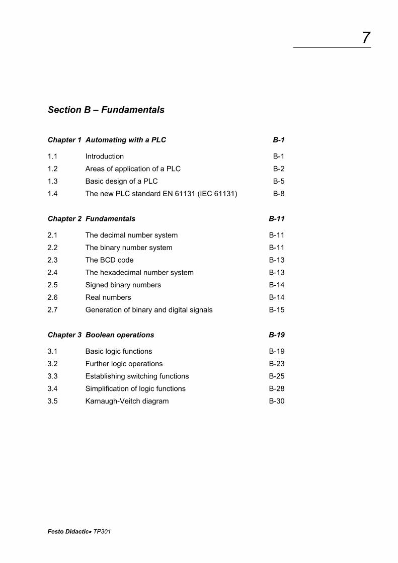
Section B – Fundamentals
Chapter 1 Automating with a PLC B-1
1.1 Introduction B-1
1.2 Areas of application of a PLC B-2
1.3 Basic design of a PLC B-5
1.4 The new PLC standard EN 61131 (IEC 61131) B-8
Chapter 2 Fundamentals B-11
2.1 The decimal number system B-11
2.2 The binary number system B-11
2.3 The BCD code B-13
2.4 The hexadecimal number system B-13
2.5 Signed binary numbers B-14
2.6 Real numbers B-14
2.7 Generation of binary and digital signals B-15
Chapter 3 Boolean operations B-19
3.1 Basic logic functions B-19
3.2 Further logic operations B-23
3.3 Establishing switching functions B-25
3.4 Simplification of logic functions B-28
3.5 Karnaugh-Veitch diagram B-30

TP301 Festo Didactic
8
Chapter 4 Design and mode of operation of a PLC B-33
4.1 Structure of a PLC B-33
4.2 Central control unit of a PLC B-35
4.3 Function mode of a PLC B-37
4.4 Application program memory B-39
4.5 Input module B-41
4.6 Output module B-43
4.7 Programming device/Personal computer B-45
Chapter 5 Programming of a PLC B-47
5.1 Systematic solution finding B-47
5.2 EN 61131-3 (IEC 61131-3) structuring resources B-50
5.3 Programming languages B-54
Chapter 6 Common elements of programming languages B-57
6.1 Resources of a PLC B-57
6.2 Variables and data types B-60
6.3 Program B-70
Chapter 7 Function block diagram B-85
7.1 Elements of function block diagram B-85
7.2 Evaluation of networks B-85
7.3 Loop structures B-87
Chapter 8 Ladder diagram B-89
8.1 Elements of ladder diagram B-89
8.2 Functions and function blocks B-92
8.3 Evaluation of current rungs B-93

Festo Didactic TP301
9
Chapter 9 Instruction list B-95
9.1 Instructions B-95
9.2 Operators B-96
9.3 Functions and function blocks B-97
Chapter 10 Structured text B-99
10.1 Expressions B-99
10.2 Statements B-101
10.3 Selection statements B-103
10.4 Iteration statements B-106
Chapter 11 Sequential function chart B-111
11.1 Introduction B-111
11.2 Elements of sequential function chart B-111
11.3 Transitions B-120
11.4 Steps B-123
11.5 Example B-135
Chapter 12 Logic control systems B-139
12.1 What is a logic control system B-139
12.2 Logic control systems without latching properties B-139
12.3 Logic control systems with memory function B-145
12.4 Edge evaluation B-148
Chapter 13 Timers B-153
13.1 Introduction B-153
13.2 Pulse timer B-154
13.3 Switch-on signal delay B-156
13.4 Switch-off signal delay B-158

TP301 Festo Didactic
10
Chapter 14 Counter B-161
14.1 Counter functions B-161
14.2 Incremental counter B-161
14.3 Decremental counter B-165
14.4 Incremental/decremental counter B-167
Chapter 15 Sequence control systems B-169
15.1 What is a sequence control system B-169
15.2 Function chart to IEC 60848 B-169
Chapter 16 Commissioning and operational safety of a PLC B-175
16.1 Commissioning B-175
16.2 Operational safety of a PLC B-177
Chapter 17 Communication B-183
17.1 The need for communication B-183
17.2 Data transmission B-183
17.3 Interfaces B-184
17.4 Communication in the field area B-185
Appendix
A Bibliography of illustrations B-187
B Bibliography of literature B-189
C Guidelines and standards B-191
D Glossary B-193
E Index B-199
Festo Didactic TP301
11
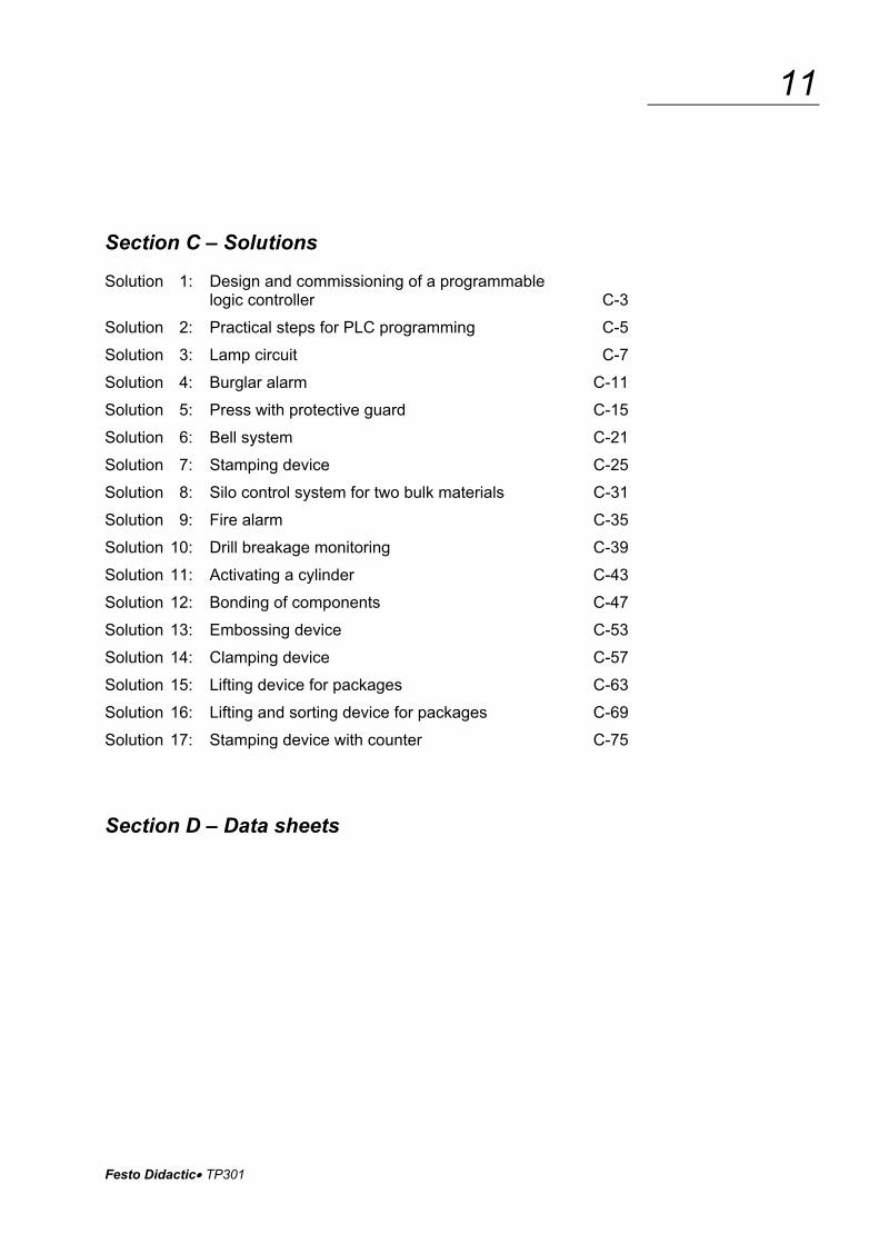
Section C – Solutions
Solution 1: Design and commissioning of a programmable logic controller C-3
Solution 2: Practical steps for PLC programming C-5
Solution 3: Lamp circuit C-7
Solution 4: Burglar alarm C-11
Solution 5: Press with protective guard C-15
Solution 6: Bell system C-21
Solution 7: Stamping device C-25
Solution 8: Silo control system for two bulk materials C-31
Solution 9: Fire alarm C-35
Solution 10: Drill breakage monitoring C-39
Solution 11: Activating a cylinder C-43
Solution 12: Bonding of components C-47
Solution 13: Embossing device C-53
Solution 14: Clamping device C-57
Solution 15: Lifting device for packages C-63
Solution 16: Lifting and sorting device for packages C-69
Solution 17: Stamping device with counter C-75
Section D – Data sheets

TP301 Festo Didactic
12

Festo Didactic TP301
13
Technology package TP301
“ Programmable logic controllers“
The technology package TP301 "Programmable logic controllers" is a component part of the Festo Didactic Learning System for Automation and Technology and forms the basic level of TP300.
The training aims of TP301 are to learn how to program programmable logic controllers and to teach the fundamentals for creating programs in the programming languages ’ladder diagram’ (LD), ’function block dia-gram’ (FBD), ’instruction list’ (IL), ’structured text’ (ST) and ’sequential function chart’ (SFC). Programming is effected in accordance with EN 61131-3 (IEC 61131-3).
You have the option of using this workbook in conjunction with alterna-tive programmable logic controllers by different manufacturers.
A basic knowledge of electro-pneumatics and sensor technology is rec-ommended to work through technology package TP301.
The exercises in TP301 deal with the following main topics:
Components of a programmable logic controller
PLC programming to EN 61131 (IEC 61131)
Basic logic operations
Logic control systems
Sequence control systems
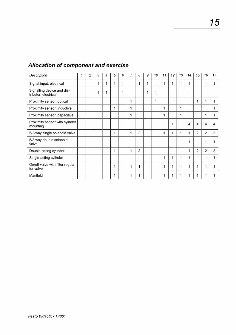
The allocation of components and exercises can be seen from the com-ponent/exercise table.
TP301 Festo Didactic
14
Layout of this workbook
The workbook is structured as follows:
Section A – Course
Section B – Fundamentals
Section C – Solutions
Section D – Appendix
Section A – Course teaches the programming of programmable logic controllers with the help of a series of progressive exercises.
Any necessary technical knowledge required for the implementation of an exercise is provided at the beginning. Functions are limited to the most elementary requirements. More detailed knowledge may be gained in section B.
Section C – Solutions provides the solutions to the exercises with brief explanations.
Section B – Fundamentals contains generally applicable technical knowledge to supplement the training contents of the exercises in Sec-tion A. Theoretical links are established and the necessary technical terminology explained with the help of examples. An index provides an easy means of locating terminology.
Section D – Appendix which contains data sheets of the used compo-nents.
Festo Didactic TP301
15
Allocation of component and exercise
Description 1 2 3 4 5 6 7 8 9 10 11 12 13 14 15 16 17
Signal input, electrical 1 1 1 1 1 1 1 1 1 1 1 1 1
Signalling device and dis-tributor, electrical
1 1 1 1 1
Proximity sensor, optical 1 1 1 1 1
Proximity sensor, inductive 1 1 1 1 1
Proximity sensor, capacitive 1 1 1 1 1
Proximity sensor with cylinder mounting
1 4 4 4 4
5/2-way single solenoid valve 1 1 2 1 1 1 1 2 2 2
5/2-way double solenoid valve
1 1 1
Double-acting cylinder 1 1 2 1 2 2 2
Single-acting cylinder 1 1 1 1 1 1
On/off valve with filter regula-tor valve
1 1 1 1 1 1 1 1 1 1
Manifold 1 1 1 1 1 1 1 1 1 1
TP301 Festo Didactic
16
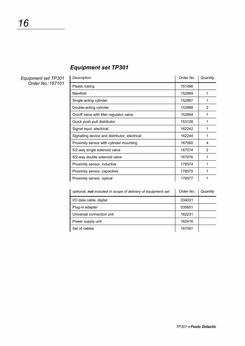
Equipment set TP301
Description Order No. Quantity
Plastic tubing 151496
Manifold 152869 1
Single-acting cylinder 152887 1
Double-acting cylinder 152888 2
On/off valve with filter regulator valve 152894 1
Quick push-pull distributor 153128 1
Signal input, electrical 162242 1
Signalling device and distributor, electrical 162244 1
Proximity sensor with cylinder mounting 167060 4
5/2-way single solenoid valve 167074 2
5/2-way double solenoid valve 167076 1
Proximity sensor, inductive 178574 1
Proximity sensor, capacitive 178575 1
Proximity sensor, optical 178577 1
optional, not included in scope of delivery of equipment set Order No. Quantity
I/O data cable, digital 034031
Plug-in adapter 035651
Universal connection unit 162231
Power supply unit 162416
Set of cables 167091
Equipment set TP301 Order No.:167101

Festo Didactic TP301
17
Notes on safety
The following notes should be followed in the interest of safety:
Mount all components securely on the board.
Do not switch on compressed air until all line connections have been established and secured.
Proceed with care when switching on the compressed air. Cylinders may advance or retract as soon as the compressed air is switched on.
Switch off air supply immediately if air lines become detached. This prevents accidents.
Do not disconnect air lines under pressure.
Do not exceed the permitted working pressure of 8 bar (800kPa).
Observe general safety regulations in accordance with EN 60204-1 (IEC 60204-1).
Use only extra-low voltages of up to 24 V DC.
Observe the data sheets referring to the individual components, in particular all notes regarding safety.

TP301 Festo Didactic
18
Operating notes
The following rules should be observed when constructing a circuit:
Block output 2 of the valve, if a single-acting cylinder is actuated by a 5/2-way single solenoid valve in a circuit.
4
5
2
3
1
Input signals, which would result from an actual production process sequence, are reproduced in part by signals via push buttons or switches.
Fig. 2: Plug for output 2
of a 5/2-way valve
TP301 • Festo Didactic
A-1
Section A – Course
Components of a programmable logic controller
Exercise 1: Design and commissioning of a programmable logic controller Components of a PLC A-3
Programming to EN 61131 (IEC 61131)
Exercise 2: From problem to solution – taking into consideration EN 61131 (IEC 61131) Practical steps for PLC programming A-11
Basic logic operations
Exercise 3: Lamp circuit The assignment function A-19
Exercise 4: Burglar alarm The NOT function A-29
Exercise 5: Press with protective guard The AND function A-39
Exercise 6: Bell system The OR function A-49
Logic control systems without latching properties
Exercise 7: Stamping device Combination of AND/OR/NOT A-59
Exercise 8: Silo control system for two bulk materials Combination circuit with branching A-69
TP301 • Festo Didactic
A-2
Logic control systems with latching properties
Exercise 9: Fire alarm Setting an output A-77
Exercise 10: Drill breakage monitoring Setting and resetting an output A-85
Exercise 11: Activating a cylinder Signal edges A-95
Logic control systems with time response
Exercise 12: Bonding of components Pulse A-107
Exercise 13: Embossing device Switch-on signal delay A-117
Exercise 14: Clamping device Switch-off signal delay A-127
Sequence control systems
Exercise 15: Lifting device for packages Linear sequence A-137
Exercise 16: Lifting and sorting device for packages Alternative branching A-155
Exercise 17: Stamping device with counter Counting cycles A-167
TP301 • Festo Didactic
A-3
Exercise 1
Programmable logic controllers
Design and commissioning of a programmable logic controller Components of a PLC
� To be able to explain the basic design and mode of operation of a PLC
� To be able to configure and commission a PLC
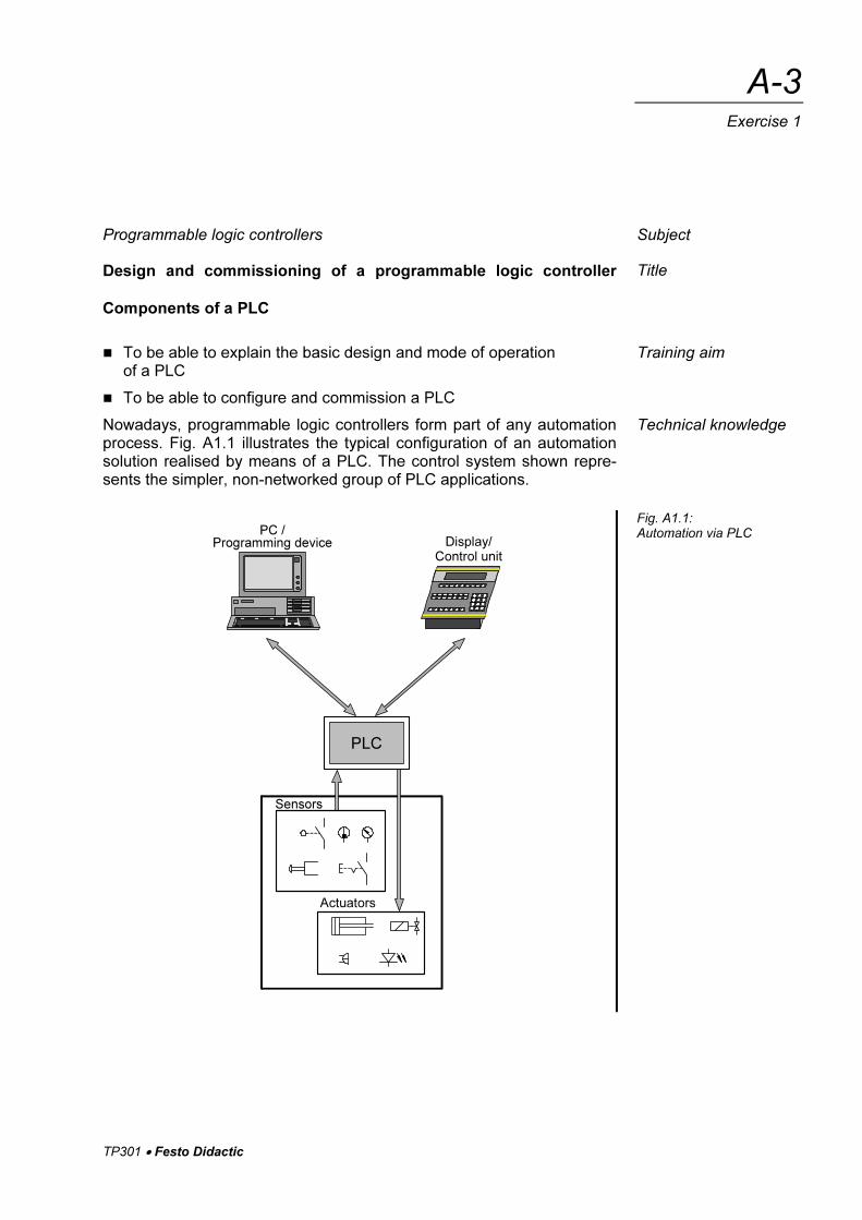
Nowadays, programmable logic controllers form part of any automation process. Fig. A1.1 illustrates the typical configuration of an automation solution realised by means of a PLC. The control system shown repre-sents the simpler, non-networked group of PLC applications.
PLC
Display/Control unit
PC /Programming device
Actuators
Sensors
Subject
Title
Training aim
Technical knowledge
Fig. A1.1: Automation via PLC
TP301 • Festo Didactic
A-4
Exercise 1
The basic components of the control system are:
� Programmable logic controller (PLC) By this, we understand the electronic modules through which all of the system or machine functions to be controlled are addressed and activated in a logic sequence.
� Sensors These components are located directly on the system or machinery be controlled, through to which the PLC is communicated actual statuses.
� Actuators These components are located directly on the system or machinery to be controlled, through which the PLC is able to change or influence statuses and as such the technical process.
� PC or programming device This is used to create the program containing the logic of the system or machinery to be controlled and to transfer this to the memory of the PLC. At the same time, these programming tools also provide sup-porting functions for the testing of the PLC program and commission-ing of the controller.
� Display and control units These enables you to monitor and influence the operation of the sys-tem or machinery.
Programmable logic controller
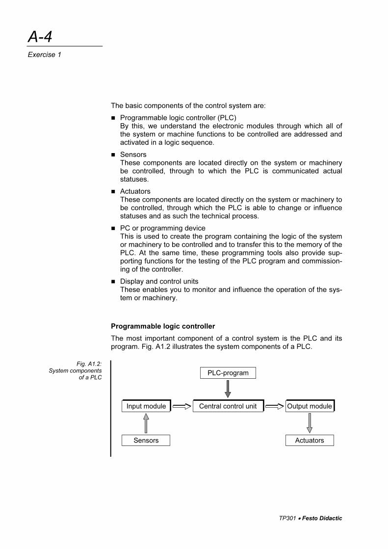
The most important component of a control system is the PLC and its program. Fig. A1.2 illustrates the system components of a PLC.
PLC-program
Central control unitInput module Output module
ActuatorsSensors
Fig. A1.2: System components
of a PLC
TP301 • Festo Didactic
A-5
Exercise 1
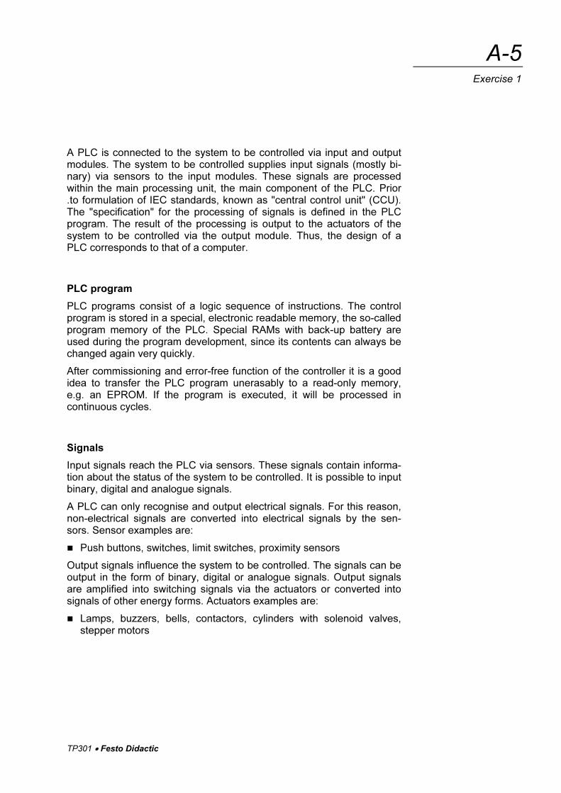
A PLC is connected to the system to be controlled via input and output modules. The system to be controlled supplies input signals (mostly bi-nary) via sensors to the input modules. These signals are processed within the main processing unit, the main component of the PLC. Prior .to formulation of IEC standards, known as "central control unit" (CCU). The "specification" for the processing of signals is defined in the PLC program. The result of the processing is output to the actuators of the system to be controlled via the output module. Thus, the design of a PLC corresponds to that of a computer.
PLC program
PLC programs consist of a logic sequence of instructions. The control program is stored in a special, electronic readable memory, the so-called program memory of the PLC. Special RAMs with back-up battery are used during the program development, since its contents can always be changed again very quickly.
After commissioning and error-free function of the controller it is a good idea to transfer the PLC program unerasably to a read-only memory, e.g. an EPROM. If the program is executed, it will be processed in continuous cycles.
Signals
Input signals reach the PLC via sensors. These signals contain informa-tion about the status of the system to be controlled. It is possible to input binary, digital and analogue signals.
A PLC can only recognise and output electrical signals. For this reason, non-electrical signals are converted into electrical signals by the sen-sors. Sensor examples are:
� Push buttons, switches, limit switches, proximity sensors
Output signals influence the system to be controlled. The signals can be output in the form of binary, digital or analogue signals. Output signals are amplified into switching signals via the actuators or converted into signals of other energy forms. Actuators examples are:
� Lamps, buzzers, bells, contactors, cylinders with solenoid valves, stepper motors
TP301 • Festo Didactic
A-6
Exercise 1
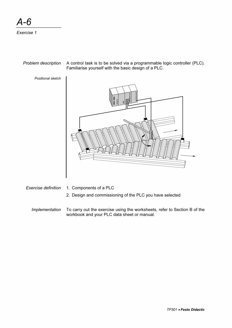
A control task is to be solved via a programmable logic controller (PLC). Familiarise yourself with the basic design of a PLC.
1. Components of a PLC
2. Design and commissioning of the PLC you have selected
To carry out the exercise using the worksheets, refer to Section B of the workbook and your PLC data sheet or manual.
Problem description
Positional sketch
Exercise definition
Implementation
TP301 • Festo Didactic
A-7
Exercise 1
WORKSHEET
1.1 Components of a PLC
Question 1: What are the basic components of a programmable logic controller?
Question 2: What are the basic modules making up the central control unit of a pro-grammable logic controller?
TP301 • Festo Didactic
A-8
Exercise 1
Question 3: How is electrical isolation achieved between sensor/actuator signals and the PLC?

TP301 • Festo Didactic
A-9
Exercise 1
WORKSHEET
1.2 Design and commissioning of the PLC you have selected
Enter the technical data of the selected programmable logic controller in the table below.
Criteria Technical data
Operating voltage
Nominal voltage
Permissible voltage range
Current consumption
Inputs
Number
Input current
Input level
Outputs
Number
Switching logic
Output voltage
Output current
Configure the PLC in accordance with the notes in the relevant data sheet or manual.
Technical data
TP301 • Festo Didactic
A-10
Exercise 1