progress of the remanta project on mav with flapping … · progress of the remanta project on mav...
TRANSCRIPT

PROGRESS OF THE REMANTA PROJECT ON MAV WITH FLAPPING WINGS
Agnès Luc-Bouhali
Office National d’Études et de Recherches Aérospatiales (ONERA)
Centre de Palaiseau, Chemin de la Hunière, 91761 Palaiseau Cedex, France
ABSTRACT Since 2002 a home project (REMANTA for REsearch programme on Microvehicle And New Technologies Application) has been carried out in order to improve our knowledge on science fields required for realizing a Flapping Wing Micro Air Vehicle. This primary project will stop at the end of year 2006. This concept needs to merge different skills and to develop new control and actuator concepts for building an agile MAV able to hover and cruise. The three research topics are the following ones:
• Flight dynamics and control • Low Reynolds number aerodynamics • Light materials, structures and actuators
This paper takes stock of the work done until now and presents the different demonstrators that were realized. With a simplified version of the 6ddl flight mechanics model OSCAB the optimization of the flapping kinematics has been made in open loop. Command and control in closed loop have been investigated and controllability was proved. Two different mechanisms have been built and used in hydrodynamic experiments in order to measure unsteady aerodynamic coefficients in low Reynolds Number domain. The data base obtained is available for comparison with numerical simulations or other experimental results. Simplified laws have been identified and put into the models. Moreover the concept of wing actuation based on resonant thorax type has been evaluated. 2ddl mathematical models have been conceived and kinematics demonstrators have been built in order to characterize the induced movements and displacements. Ultra light wings have been made whose flexibility may be adjusted by increasing/decreasing the number of carbon tows or the spacing of the ribs. The REMANTA project is ready to go farther until the realization of a flying demonstrator. We are looking for funding and collaboration with other research teams.
1. INTRODUCTION Since year 2002, ONERA federates various research teams round a research project dealing with flapping-wing MAV concept. The goal of this project, named REMANTA (for REsearch program on Microvehicle And New Technologies Application) is not to build or design a MAV demonstrator, but to improve the scientific and technical knowledge required for designing such a vehicle capable of hovering and cruising flights. Nevertheless, the µvehicle (total wing span less than 15 to 20 cm) we have in mind should hover and fly at a maximum speed of 10 m/s, with a total mass of 50 to 100g, with a maximal flapping frequency of about 30 to 40 Hz. With such dimensions, the Reynolds number (based on the chord length) is about a few 105 during cruising flight and 104 during hovering. Three research topics are addressed:
• Flight dynamics and control • Low Reynolds number aerodynamics • Light materials, structures and actuators

The other important issues, such as on-board energy, sensors and on-board computer, data link, task distribution, are not studied in this project firstly in order to not disperse the efforts too widely and secondly because these things are important only when one takes the decision to build a complete demonstrator. The REMANTA project is nearly finished, as home project. This paper will take stock of the gained results. Before presenting the status of each issue, we will firstly recall some information that can be found in the open literature concerning the flapping wing propulsion, even if it is now well-known. 2. FLAPPING WING PROPULSION We focused our search on animals able to hover and cruise. The only bird which is able to hover is the hummingbird. Although it is a bird, the morphology of its wings involves a mode of operation very similar to an insect’s one. The wing motion is entirely determined from the shoulder joint (elbow and wrist joints are fused) and the wing flapping kinematics of the upstroke and downstroke are very similar. During stationary flight, the stroke plane is horizontal ; the flap angle (stroke amplitude) varies from -60° to +60°, the rotation angle of the wing from -45° to +45° and the frequency is approximately 25 Hz [1]. This kind of flight is extremely power-consuming. The hummingbirds may also cruise with considerable efficiency. In this case the stroke angle is vertical like other birds. The hummingbirds are at the frontier between birds and insects. Most of insects may hover [2]. They may have two or four wings that operate independently or not. Their wings, when they are unfoldable, are passive structures without muscles: they are not actively controlled [3]. The movement is generated at the wing root by direct and/or indirect muscles that control wing beat, rotation and torsion. The required power is moderate due to the use of the resonance phenomenon in the thorax (for very high frequencies). The kinematics can be described in the following figure. Generally, the stroke angle and the flapping frequency are nearly constant in time.
Figure 1 – a) Flapping speed and wing rotation speed during a flapping cycle
b) Flap angle (lambda) and wing rotation (nu) during a flapping cycle Each insect is then characterized by its particular kinematics, flapping frequency and stroke angle that can be linked together.

All these considerations have suggested that flexible insect-like wings may be simpler to realize, easier to move without active control system and certainly less power consuming than articulated birdlike wings, even if the actuator system is not yet well-defined. The major difficulty will be to find kinematics effective for both hovering and cruising, with the same actuator system at the wing root and also to determine the control laws and the associated parameters.
2. FLIGHT MECHANICS AND CONTROL Our purpose is then to build a numerical flight mechanics model that can be used in order to test and then to choose control strategies. A simulation model called OSCAB (for Outil de Simulation de Concept d’Ailes Battantes) has been realized [4, 5]. An exact mathematical formulation with 6 dof describes the kinematics of the articulated body (fuselage and two independent wings). The wing movement is described by 4 angles: the stroke plane, the lagging angle (both considered as constant during the cycle), the flap angle lambda and the rotation angle nu. The kinematics parameters are described by parametric functions and also by neural networks. Simplified longitudinal model was also established in order to address system analysis, optimization and control problems (Figure 2). The major difficulty is to have aerodynamic models well-adapted to the phenomena encountered around such a vehicle. Due to low Reynolds number conditions, steady aerodynamics are not always sufficient to explain insect or bird flight. A lot of research has been done and is currently done in order to understand and quantify the phenomena. The Robofly experiment [6] is the main information source and concerns a Reynolds number range of around a few hundreds. That is lower than the expected one for our application. Otherwise, kinematics for cruise or hovering flights are very different, either concerning the flapping frequencies or variation speeds, or concerning the angle amplitudes. These important limitations led us to define an aerodynamic task in the REMANTA project that is described in the next chapter. Nevertheless, different existing unsteady models were chosen and implemented, such as rotational circulation and added mass, to create a complete simulation model.
Identification
Experimental Data
Aero Models
OSCAB Model
6dof Fight mechanics Modelaero model by slices
Analysis & Optimisation in the beat cycle
Control in closed loopSimplified
OSCAB Model
Longitudinal or lateral Model1 slice
Aero Models
Open Data
Viewer
Identification
Experimental Data
Aero Models
OSCAB Model
6dof Fight mechanics Modelaero model by slices
Analysis & Optimisation in the beat cycle
Control in closed loopSimplified
OSCAB Model
Longitudinal or lateral Model1 slice
Aero Models
Open Data
Viewer
Figure 2 – Task Organization

First of all, influence of the phase between the rotation and the flapping of the wing has been studied, together with the time history of the wing rotation angle. The optimization of the kinematics within the flapping cycle was made in open loop [5]. Kinematics were also found that let the vehicle to evolve from stationary flight to cruise flight, changing only one or two parameters and being optimal. For example the Figure 3 shows that using optimized parameters at V=0,1m/s and stroke plane=50°, the variation of the stroke plane leads to a lift variation lower than 10% for a speed variation from 0m/s to 0.16 m/s.
Figure 3 – Optimization for experimental conditions (in water):
flapping=sinus function – maximization of mean lift – mean drag=0 Red line: optimized parameters – Blue line: blocked parameters
Furthermore the command and control in closed loop has been investigated and controllability was proven. A non linear command law has been developed based on cycle-averaged states. A complete mission with hovering, acceleration, cruise and manoeuvring can be achieved without any additional control surfaces like tail or flaps. In that case, both rigid wings were considered as independent, and the actuators were simulated by a 1st degree transfer function with a time constant equal to ¼ of the flapping period.

4. EXPERIMENTAL AERODYNAMICS Considering that the need of aerodynamic data for the flight mechanics models, in a domain of low Reynolds numbers is not well-documented (104-105), we decided to use an experimental methodology. The gathering of instantaneous data (Cd, CL, Cm…) will provide us with an experimental data base. These data should also later help for code validation. Unlike conventional aircrafts which are usually too large to be tested at scale 1 in ground facilities, mini or micro UAV are sufficiently small to be tested at actual size. On the contrary, the size of the model might have to be increased due to realization costs or instrumentation difficulties. Similitude rules have to be respected if we want to have correct measurements: not only the Reynolds number but also the Strouhal number (or the reduced frequency) must be identical between flight and test conditions. The kinematics must also be the same. As we wanted to measure torques and forces, we chose to use water tank or tunnel as test facilities: inertial forces will be, then, much lower than aero or hydrodynamic forces. Two existing facilities are involved in the project. In the water tank at ONERA/Lille (Figure 4), a 5- components balance has been specially developed for the REMANTA project. In the water tunnel at ONERA/Toulouse visualisations with laser tomography and image acquisitions were performed.
Figure 4 – Lille test facility involved in the REMANTA project Figure 5 - Coupled mechanism
A mechanism was studied and built (see Figure 5) to move one rigid wing with 2D (plunging and pitching) or 3D (flapping and pitching) kinematics: this device can reproduce bird-like kinematics, with moderate stroke and incidence amplitudes. However, since only one motor is used for generating the kinematics, flapping and pitching are linked together. The airfoil of the wing is a NACA 0012: its thickness is sufficient to incorporate the balance inside the structure, and the model is well documented for both steady and unsteady aerodynamics.

Test campaigns have been conducted in years 2003, 2004 and 2005 [7, 8]. For 2D tests, the reduced frequencies and the Reynolds numbers (based on the chord length and calculated with the relative speed) are respectively in the range [0.04- 0.25] and [104-105]. Figure 6 shows typical results.
n°423 V=0,505 f=0.493 ° ⊇° ⊇° ⊇° ⊇=45° io= 10°
-0,2
0,0
0,2
0,4
0,6
0,8
1,0
1,2
1,4
1,6
0,0 0,2 0,4 0,6 0,8 1,0 1,2 1,4 1,6 1,8 2,0
Temps
Cz Cx Cmx
-30
-25
-20
-15
-10
-5
0
5
10
15
20
25
30CxCzCmxi_mécai_aéroZ
i° Z
Figure 6 – Experimental results – Test case 423
The aerodynamic laws derived from these experimental data through identification process [9] will feed the flight mechanics models. Comparisons have been made between OSCAB and experimental results. Figure 7 shows as example the test case 473: the use of steady aerodynamic model and the change of incidence reference point lead to a rather good agreement.
Figure 7 –CL(α) obtained from water tunnel tests compared with simplified models
Red line: measurements – Green line: first model - Blue line: improved model
Activities on numerical simulations have been undertaken (Figure 8) in order to identify the physical phenomena linked with the vortices, occurring during the flapping. Since November 2005 a PhD is now in progress and will provide useful information [10].
Figure 8 – Example of 2D plunging computation
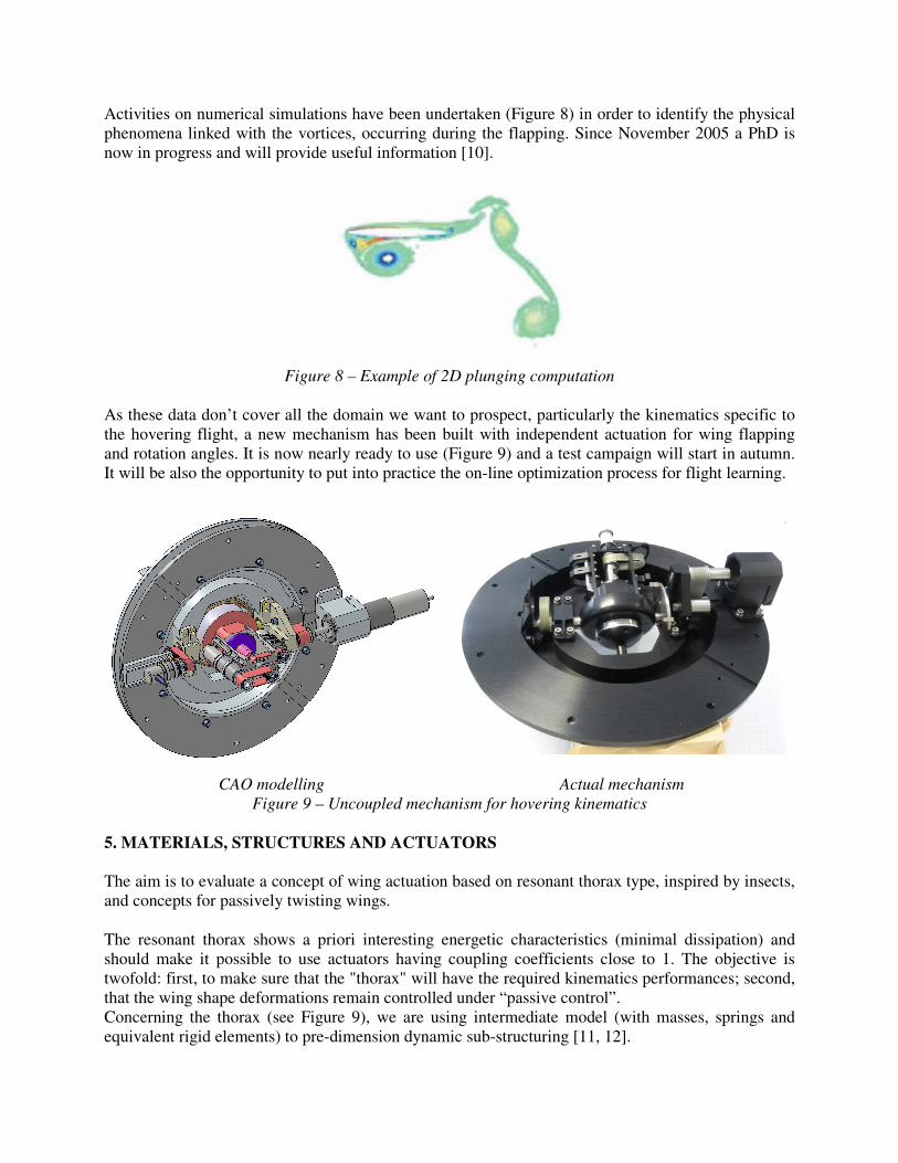
As these data don’t cover all the domain we want to prospect, particularly the kinematics specific to the hovering flight, a new mechanism has been built with independent actuation for wing flapping and rotation angles. It is now nearly ready to use (Figure 9) and a test campaign will start in autumn. It will be also the opportunity to put into practice the on-line optimization process for flight learning.
CAO modelling Actual mechanism Figure 9 – Uncoupled mechanism for hovering kinematics
5. MATERIALS, STRUCTURES AND ACTUATORS The aim is to evaluate a concept of wing actuation based on resonant thorax type, inspired by insects, and concepts for passively twisting wings. The resonant thorax shows a priori interesting energetic characteristics (minimal dissipation) and should make it possible to use actuators having coupling coefficients close to 1. The objective is twofold: first, to make sure that the "thorax" will have the required kinematics performances; second, that the wing shape deformations remain controlled under “passive control”. Concerning the thorax (see Figure 9), we are using intermediate model (with masses, springs and equivalent rigid elements) to pre-dimension dynamic sub-structuring [11, 12].

Figure 9 – Bio-inspired thorax
Realization of prototypes is essential to check the suggested concepts. Two mock-ups have been built (Figure 10). The kinematics have been obtained from flight mechanics studies in order to precise the different parameters defining the concept: flapping frequencies, angle amplitudes, wished displacements, applied forces. Current works are in open loop, but soon a closed-loop approach will be used.
Scale~5 Scale~1
Figure 10 – Kinematics demonstrators Concerning the wings, examination of insect wings has suggested a fabrication of a wire-mesh surrounded by a thin membrane. This wire-mesh processed of prepregs made of carbon fibers and epoxy resin offers an attractive solution (see Figure 11). Flexibility may be adjusted by increasing/decreasing the number of carbon tows. A thermoplastic polyester film pasted on the wire-mesh constitutes an interesting envelope to complete this wing fabrication. Tested by dynamic flexural, this realization is quite suitable to meet the expected mechanical requirements from a MAV wing.

Figure 11 – Wing concept and demonstrator
However, with the present structural version, first tests showed that the wing is not rigid enough in bending (insufficient flexural stiffness of the relevant constituted network).The use of small masses like a pterostigma (Figure 12) seems a good way for having torsional deformation induced by flapping movement. This work is still in progress and will later provide more results.
Figure 12 – Wing deformation during flapping
6. CONCLUSIONS AND FUTURE DEVELOPMENTS The work completed up to now has allowed developing a flight mechanics model which has been partly verified. Optimisation studies have been made. Non linear command laws for control in closed loop have been established. Concerning unsteady aerodynamic models for low Reynolds number, experiments with a coupled mechanism have been conducted and a data base has been created for forward flight. A new mechanism with independent actuation for wing flapping and rotation angles is now available. It allows reproducing kinematics specific to hovering flight. The test campaign will begin in autumn. First achievements of composite wings have been obtained, as well as an initial concept of a resonant thorax. After kinematics characterization these mock-ups will be used for testing wing structure improvements. It is the first step before addressing aeroelasticity problems. After 4 ½ years, the REMANTA project is ready to go farther until the realization of a flying demonstrator. It has contributed to gather different competences and to form a multidisciplinary team which represents an active asset for further practical developments or international cooperations.

ACKNOWLEDGEMENT The authors would like to acknowledge the participants in the PRF REMANTA: J.Ancelle, J.L.Andro, C.Arrouvel, B.Aupoix, J.P.Bourez, Ph.Choy, B.Danet, B.Dangvu, J.Fort, O.Giraudo, G.Heid, L.Jacquin, Th.Le Moing, Ph.Leconte, Ch.Marais, I.Mary, Ph.May, A.Mavel, D.Osmont, J.B.Paquet, J.L.Pastre, A.Peray, L.Planckaert, T.Rakotomamonjy, D.Sipp. REFERENCES [1] D.L.Altshuler, R.Dudley, Kinematics of hovering hummingbird flight along simulated and natural elevational gradients, The Journal Of Experimental Biology 206, 3139-3147 (2003) [2] A.K.Brodsky, The evolution of Insect Flight, Ocford Science Publication, 1994 [3] S.A.Combes, T.L.Daniel, Flexural stiffness in insect wings I. Scaling on the influence of wing venation, The Journal Of Experimental Biology 206, 2979–2987 (2003) [4] T.Rakotomamonjy, T.LeMoing, M.Ouladsine, Simulation of a flapping-wing Micro Air Vehicle, EMAV 2004, Braunschweig, Germany, July 2004 [5] T.Rakotomamonjy, M.Ouladsine, T.LeMoing, Modelisation and kinematics optimization for a flapping-wing Micro Air Vehicle, submitted to Journal of Aircraft, 2006 [6] M.H.Dickinson, F.O.Lehmann, S.P.Sane, Wing rotation and the aerodynamic basis of insect flight, Science, 284:1954-1960, June 1999 [7] J.B.Paquet, Characterization of Flapping Wings in Water Tank for µUAV, EMAV 2004, Braunschweig, Germany, July 2004 [8] J.B.Paquet, J.P.Bourez, Experiments on oscillating wings at low Reynolds Numbers, EMAV 2006, Braunschweig, Germany, July 25-26, 2006 [9] A.Péray, L.Planckaert, G.Dauphin-Tanguy, Ph.Vanheeghe, Modelling and Identification of unsteady aerodynamics at low angle of attack around a flapping-wing, IMAACA, Marseille, France, October 20-22, 2005 [10] J.Y.Andro, L.Jacquin, The three fundamental mechanisms for forward flight with flapping wings: dynamic stall, added mass reaction, wing wake interactions, EMAV 2006, Braunschweig, Germany, July 25-26, 2006 [11] D.Osmont, O.Giraudo, A Bio-inspired Structure for the Actuation of a Flapping Wings Micro Aerial Vehicle (MAV) (kinematic and structural point of view), 16th International Conference on Adaptative Structures and Technologies, Paris, France, October 9th-12th 2005 [12] D.Osmont, O.Giraudo, A simple mechanical system for a flapping wing MAV: modelling and experiments, SPIE Smart Structures and Materials Meeting, San Diego, U.S.A, February 26- March 2, 2006