project 8.1a model a button maker -...
TRANSCRIPT

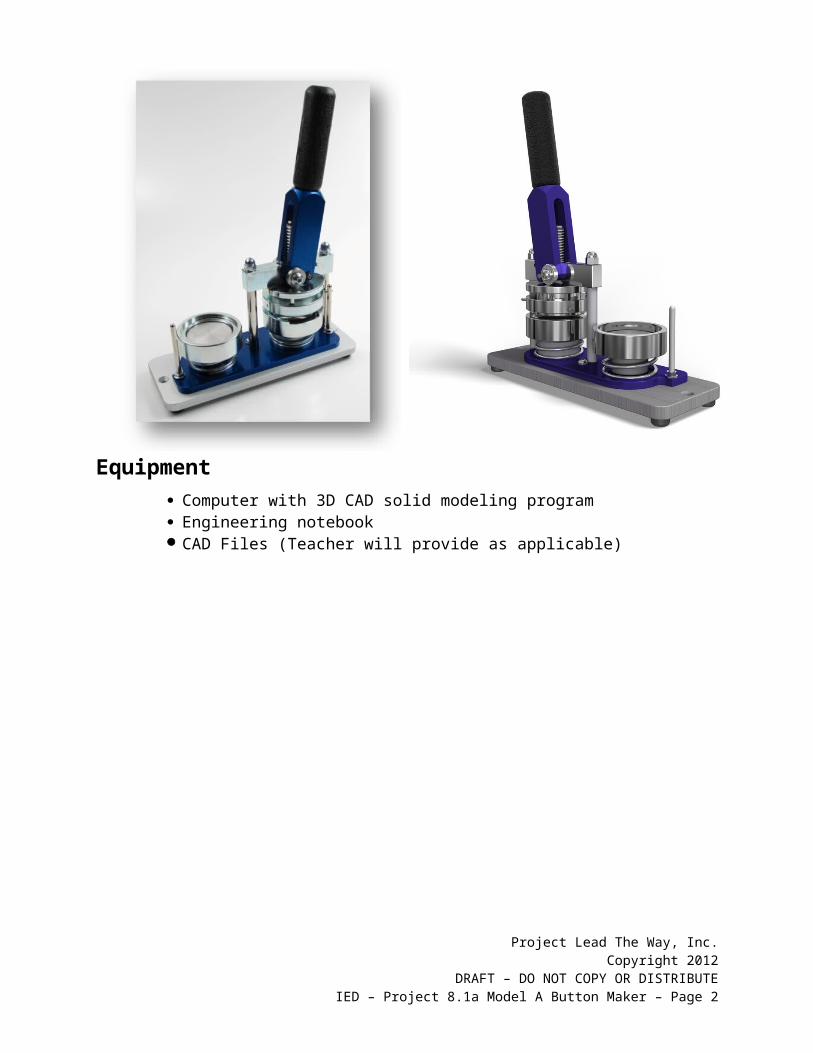
Project 8.1a Model A Button MakerIntroduction
Interpreting dimensioned drawings is an important engineering skill. Using drawings to create a computer model of a part is also important. You learned earlier in this course that a sketch is the documentation foundation for related technical work. Communicating this information effectively allows a group of people to function as a design team.
In this project you will further develop your modeling skills and your ability to use a computer as an efficient communication tool. The skills that you learned earlier in this course will be systematically applied to model the eight remaining parts needed for the Button Maker Assembly. The parts with the dimensions are listed below.
Equipment Computer with 3D CAD solid modeling program Engineering notebook CAD Files (Teacher will provide as applicable)
Project Lead The Way, Inc.Copyright 2012
DRAFT – DO NOT COPY OR DISTRIBUTEIED – Project 8.1a Model A Button Maker – Page 1
Procedure1. Model and assemble the parts and subassemblies shown using the drawings
provided.
Sub Assembly
Item PART NUMBER Required Optional
Bottom Press Assembly
Assemble
1 BASE BEARING Model2 1/4 – 20 CAP NUT Model3 SMALL SNAP RING Model4 HANDLE PIVOT PIN ModelA BASE SUB-ASSEMBLY A AssembleB LOWER DIE SUB-ASSEMBLY B AssembleC HANDLE SUB-ASSEMBLY C AssembleD UPPER DIE SUB-ASSEMBLY D Assemble
Base Sub-Assembly A
Assemble
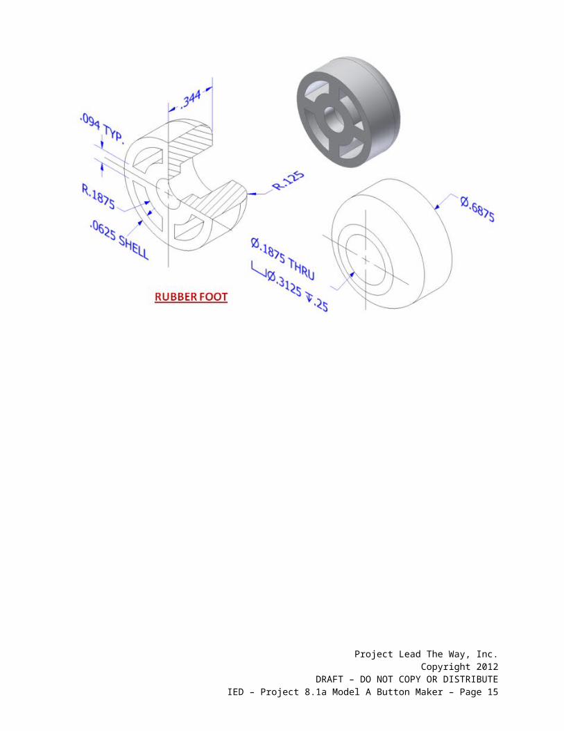
1 BASE PLATE Model2 RUBBER FOOT Model3 8-32 X 3/8 UNC SCREW Model4 VERTICAL SUPPORT Model5 5/16-18 HEX NUT Model5 5/16-18 X 9/16 BUTTON CAP SCREW Model6 RUBBER HANDLE SLEEVE Model7 METAL HANDLE INSERT Model8 7/16-14 X 1 3/8 SOCKET SET SCREW Model
Lower Die Sub-Assembly B
Assemble
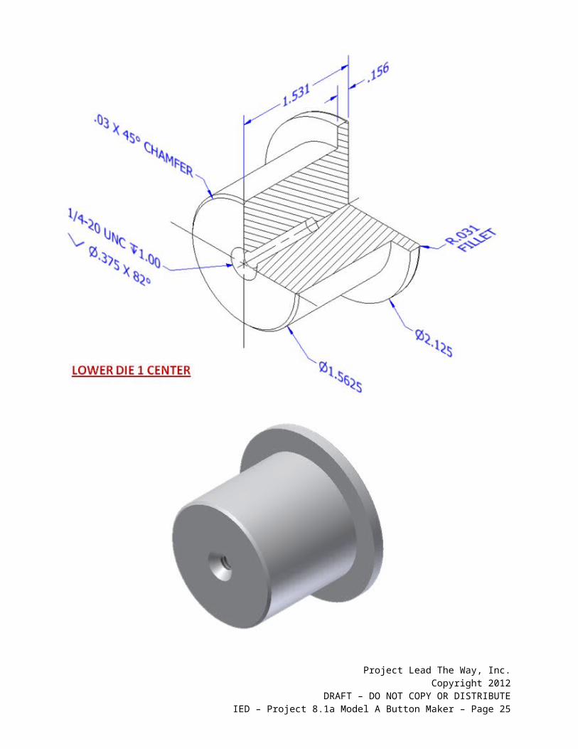
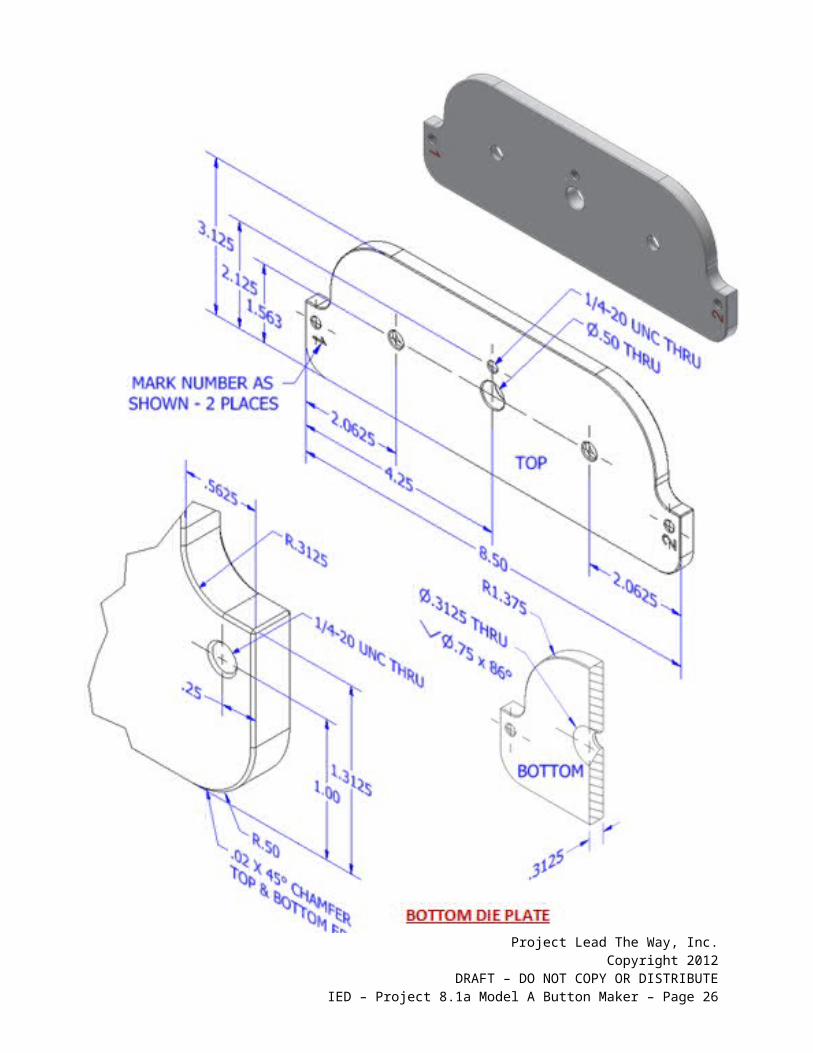
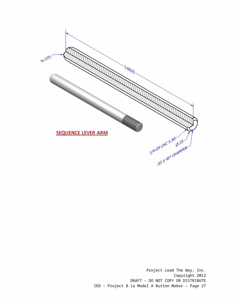
1 BOTTOM DIE PLATE Model2 5/16-18 HEX NUT Model3 SEQUENCE LEVER ARM Model4 ¼ WASHER Model5 ¼-20 X 5/16 BUTTON CAP SCREW Model6 LOWER DIE 1 OUTER RING Model7 LOWER DIE 1 CENTER Model8 ¼-20 X ¾ SOCKET HEAD SCREW Model9 LOWER DIE 2 CENTER Model
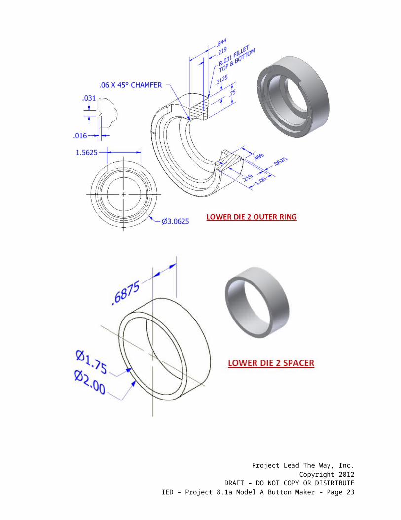
10 LOWER DIE 2 OUTER RING Model11 LOWER DIE 2 SPACER Model12 BOTTOM DIE SPRING Model
Handle Sub-Assembly C
Assemble
1 HANDLE BODY Model2 ROLLER SPACER Model3 ROLLER INNER BEARING Model4 ROLLER OUTER BEARING Model
Upper Die Sub-Assembly D
Assemble
1 UPPER DIE CENTER SUPPORT Model
Project Lead The Way, Inc.Copyright 2012
DRAFT – DO NOT COPY OR DISTRIBUTEIED – Project 8.1a Model A Button Maker – Page 2

2 LARGE SNAP RING Model3 HANDLE RETENTION PIN Model4 UPPER DIE CENTER PIN Model5 UPPER DIE SPRING Model6 UPPER OUTER RING Model7 UPPER DIE PRESSURE RING Model8 #8-32 X 0.7 SCREW Model9 UPPER DIE CENTER Model
10 ¼-20 X 1 3/16 SOCKET HEAD SCREW Model
Project Lead The Way, Inc.Copyright 2012
DRAFT – DO NOT COPY OR DISTRIBUTEIED – Project 8.1a Model A Button Maker – Page 3

Button Press TolerancesAll parts have the following tolerances:
Project Lead The Way, Inc.Copyright 2012
DRAFT – DO NOT COPY OR DISTRIBUTEIED – Project 8.1a Model A Button Maker – Page 4

X.X = +/- .020X.XX = +/- .010X.XXX = +/- .005
2. Model and assemble this subassembly shown using the drawings provided.
Project Lead The Way, Inc.Copyright 2012
DRAFT – DO NOT COPY OR DISTRIBUTEIED – Project 8.1a Model A Button Maker – Page 5

Project Lead The Way, Inc.Copyright 2012
DRAFT – DO NOT COPY OR DISTRIBUTEIED – Project 8.1a Model A Button Maker – Page 6

Project Lead The Way, Inc.Copyright 2012
DRAFT – DO NOT COPY OR DISTRIBUTEIED – Project 8.1a Model A Button Maker – Page 7

Project Lead The Way, Inc.Copyright 2012
DRAFT – DO NOT COPY OR DISTRIBUTEIED – Project 8.1a Model A Button Maker – Page 8

Project Lead The Way, Inc.Copyright 2012
DRAFT – DO NOT COPY OR DISTRIBUTEIED – Project 8.1a Model A Button Maker – Page 9

Project Lead The Way, Inc.Copyright 2012
DRAFT – DO NOT COPY OR DISTRIBUTEIED – Project 8.1a Model A Button Maker – Page 10

3. Model and assemble this subassembly shown using the drawings provided.
Project Lead The Way, Inc.Copyright 2012
DRAFT – DO NOT COPY OR DISTRIBUTEIED – Project 8.1a Model A Button Maker – Page 11

Project Lead The Way, Inc.Copyright 2012
DRAFT – DO NOT COPY OR DISTRIBUTEIED – Project 8.1a Model A Button Maker – Page 12

Project Lead The Way, Inc.Copyright 2012
DRAFT – DO NOT COPY OR DISTRIBUTEIED – Project 8.1a Model A Button Maker – Page 13

Project Lead The Way, Inc.Copyright 2012
DRAFT – DO NOT COPY OR DISTRIBUTEIED – Project 8.1a Model A Button Maker – Page 14
Project Lead The Way, Inc.Copyright 2012
DRAFT – DO NOT COPY OR DISTRIBUTEIED – Project 8.1a Model A Button Maker – Page 15
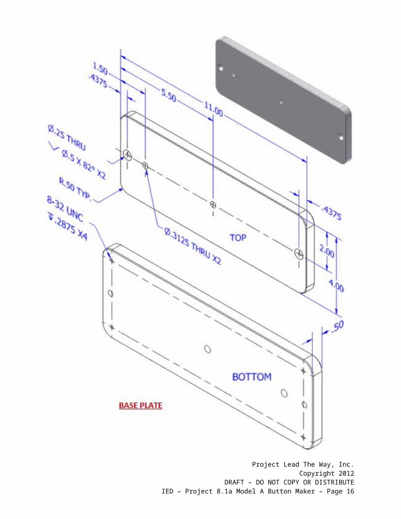
4. Model and assemble this subassembly shown using the drawings provided.
Project Lead The Way, Inc.Copyright 2012
DRAFT – DO NOT COPY OR DISTRIBUTEIED – Project 8.1a Model A Button Maker – Page 16

Project Lead The Way, Inc.Copyright 2012
DRAFT – DO NOT COPY OR DISTRIBUTEIED – Project 8.1a Model A Button Maker – Page 17

Project Lead The Way, Inc.Copyright 2012
DRAFT – DO NOT COPY OR DISTRIBUTEIED – Project 8.1a Model A Button Maker – Page 18

5. Model and assemble this subassembly shown using the drawings provided.
Project Lead The Way, Inc.Copyright 2012
DRAFT – DO NOT COPY OR DISTRIBUTEIED – Project 8.1a Model A Button Maker – Page 19

Project Lead The Way, Inc.Copyright 2012
DRAFT – DO NOT COPY OR DISTRIBUTEIED – Project 8.1a Model A Button Maker – Page 20

Project Lead The Way, Inc.Copyright 2012
DRAFT – DO NOT COPY OR DISTRIBUTEIED – Project 8.1a Model A Button Maker – Page 21

Project Lead The Way, Inc.Copyright 2012
DRAFT – DO NOT COPY OR DISTRIBUTEIED – Project 8.1a Model A Button Maker – Page 22
Project Lead The Way, Inc.Copyright 2012
DRAFT – DO NOT COPY OR DISTRIBUTEIED – Project 8.1a Model A Button Maker – Page 23

Project Lead The Way, Inc.Copyright 2012
DRAFT – DO NOT COPY OR DISTRIBUTEIED – Project 8.1a Model A Button Maker – Page 24
Project Lead The Way, Inc.Copyright 2012
DRAFT – DO NOT COPY OR DISTRIBUTEIED – Project 8.1a Model A Button Maker – Page 25
Conclusion1. Why are drawings composed of different line conventions?
2. What is the purpose of a sectional view?
3. What is the purpose of an auxiliary view?
4. Why are symbols used instead of words to identify hole types?
5. What is the format for calling out a tapped hole?
6. What advantage is there to using algebraic equations instead of numerical values when defining the dimensions of a CAD model?
Project Lead The Way, Inc.Copyright 2012
DRAFT – DO NOT COPY OR DISTRIBUTEIED – Project 8.1a Model A Button Maker – Page 26
7. What three types of constraints can be applied to CAD sketches or models?
8. How would a consumer most likely come into contact with an assembly view drawing?
9. What advantages do CAD drawings have over paper sketches?
Project Lead The Way, Inc.Copyright 2012
DRAFT – DO NOT COPY OR DISTRIBUTEIED – Project 8.1a Model A Button Maker – Page 27