project manual for - university of...
TRANSCRIPT

PROJECT MANUAL FOR:
3rd Floor Fit Out University of Missouri / Patient Care Tower
4th Floor Fit Out University of Missouri / Patient Care Tower
UMHC PCT AHU Modification University of Missouri / Patient Care Tower
PROJECT NUMBERS:
CP150752
CP150753
CP150754
AT:
UNIVERSITY OF MISSOURI – COLUMBIA, MISSOURI
FOR:
THE CURATORS OF THE UNIVERSITY OF MISSOURI
PREPARED BY:
TreanorHL Attn: Robert M. Koenig, AIA 1811 Baltimore Kansas City, Missouri 64108 Phone: 816-221-0900 Fax: 816-221-4992
Issued for Bidding
July 2, 2018


CAMPUS FACILITIES
General Services Bldg. Columbia, Missouri 65211
Telephone: (573) 882-3091
ADVERTISEMENT FOR BIDS
Sealed bids for:
PATIENT CARE TOWER – 3RD & 4TH FLOOR FITOUT AND AHU MODIFICATIONS UNIVERSITY OF MISSOURI COLUMBIA, MISSOURI PROJECT NUMBER: CP150752, CP150753, CP150754
CONSTRUCTION ESTIMATE $8,987,551 - $9,986,768
will be received by the Curators of the University of Missouri, Owner, at Campus Facilities, Planning, Design & Construction, Room L100 (Front Reception Desk), General Services Building, University of Missouri, Columbia, Missouri 65211, until 1:30 p.m., C.T., August 2, 2018 and then immediately opened and publicly read aloud.
Drawings, specifications, and other related contract information may be obtained at http://operations-webapps.missouri.edu/pdc/adsite/ad.html. Electronic bid sets are available at no cost and may be printed as desired by the plan holders. No paper copies will be issued. If paper copies are desired, it is the responsibility of the user to print the files or have them printed. Questions should be directed to the office of Planning, Design & Construction at (573) 882-0455.
Questions regarding the scope of work should be directed to Robert Koenig with TreanorHL at (816) 581-4028 or [email protected]. Questions regarding commercial conditions should be directed toJeff Fleenor at (573) 882-7356 or [email protected].
Information regarding bid results will be available the day following the bid opening by calling (573) 882-6894.
A prebid meeting will be held at 9:30 a.m., C.T., July 18, 2018 in Room 194B General Services Building, University of Missouri, Columbia, Missouri, followed by a walk-through at the site. All interested bidders are invited to attend this meeting. A walk-through of the project may be scheduled by contacting the Prebid Inspection Guide at (573) 882-2228.
A Diversity Participation goal of 10% MBE and 10% Combined WBE, DBE, Veteran Owned Business and 3% SDVE has been established for this contract.
The Owner reserves the right to waive informalities in bids and to reject any and all bids.
Individuals with special needs as addressed by the Americans with Disabilities Act may contact (573) 882-1133.
Advertisement Date: July 2, 2018
Gary L. Ward Vice Chancellor of Operations University of Missouri
DATE: July 2, 2018


THIS PAGE INTENTIONALLY LEFT BLANK

THIS PAGE INTENTIONALLY LEFT BLANK

Cert ‐03
DATE: July 2, 2018 I hereby certify that these Drawings and/or Specifications have been prepared by me, or under my supervision. I further certify that to the best of my knowledge these Drawings and/or Specifications are as required by and in compliance with Building Codes of the University of Missouri.
Eric Reuther, Engineer Specifications Division 20-25 CP150752 – 3rd Floor, CP150753 – 4th Floor Drawings: M001, MD103-MD104, MD203-MD204, M102-M104, M203-M204, M303-M304, M501-M502, M601-M605, M701-M702, M801, MG001, MG203-MG204, MG303, MG601-MG602, PD103-PD104, P102-P104, P401-P402, FP103-FP104, FPT103-FPT104 CP150754 – AHU Modification Drawings: M001, MD109A, MD109B, MD109R, M109A, M109B, M109R, M401-M403, M501, M601-604, M801, P107B, P108B, P109B, FP109

THIS PAGE INTENTIONALLY LEFT BLANK

Cert ‐04
DATE: July 2, 2018 I hereby certify that these Drawings and/or Specifications have been prepared by me, or under my supervision. I further certify that to the best of my knowledge these Drawings and/or Specifications are as required by and in compliance with Building Codes of the University of Missouri.
Austin Strieker, Engineer Specifications Division 26 - 28 CP150752 – 3rd Floor, CP150753 – 4th Floor Drawings: E001, ED101-ED102, E100, E101-E102, E201-E202, E301-E302, E401-E402, E601-E602, E701-E703, E801-E805, FA101-FA102 CP150754 – AHU Modification Drawings: E001, ED109B, ED109C, E109A, E109B, E109R, E501, E701-E704, E800

THIS PAGE INTENTIONALLY LEFT BLANK

DATE: July 2, 2018
I hereby certify that these Drawings and/or Specifications have been prepared by me, or under my supervision. I further certify that to the best of my knowledge these Drawings and/or Specifications are as required by and in compliance with Building Codes of the University of Missouri.
Monica Santos, Engineer
Specifications Division 26, 27, 28 CP150752 – 3rd Floor, CP150753 – 4th Floor Drawings: ED102, E001, E101, E102, E202, E302, E601, E602, E804, E805, FA102
Signature: Monica Santos

THIS PAGE INTENTIONALLY LEFT BLANK

TABLE OF CONTENTS
TITLE PAGE
VOLUME 1 – GENERAL REQUIREMENTS AND DIVISION 1
DIVISION 1 – GENERAL REQUIREMENTS
1.A 1.A 1-5
1.B BSQ/1-2
1.B.0 SD 1-2 1.B.1 SD 3-4 1.B.2 SD 5-6 1.B.3 SD 7 1.B.4 SD 8 1.B.5 SD 9
1.C IFB/1-5
1.D GC/1-39
1.E1.E.11.E.21.E.31.E.4
SC 1-26 HCG 1-13
SS 1- 5 EXR 1-2 RSMC1
1.E.51.E.61.E.71.E.81.E.91.E.10
CRFSMG 1-2 SDSL 1
OMML 1 CLOSL 1 SR-1
COM-1-11
1.F INDEX 1
1.G
Advertisement for Bids Certification Pages Table of Contents
Bid for Lump Sum Contract
Bidder's Statement of Qualifications
Supplier Diversity Compliance Evaluation Application for Waiver Affidavit for Affirmative Action Certifying Supplier Diversity Agencies Newspapers for Outreach to Diverse Suppliers Affidavit of Supplier Diversity Participation
Information for Bidders
General Conditions
Special Conditions Healthcare Construction Guidelines Scheduling Specification Existing Roofing Warranty Roofing System Manufacturer's Certification Contractor’s Roofing/Flashing/Sheet Metal Guarantee Shop Drawing and Submittal Log Operating Instructions and Service Manual Log Closeout Log Sustainability Report Commissioning Plan
Index of Drawings
Prevailing Wage PW 1

VOLUME 1 – DIVISIONS 1 THROUGH 14
DIVISION 1 – GENERAL REQUIREMENTS
012100 Allowances 013329 Indoor Air Quality 014000 Quality Requirements 017300 Execution 017329 Cutting and Patching 017419 Construction Waste Management
DIVISION 2 – EXISTING CONDITIONS
024116.4 Selective Demolition
DIVISION 3 – CONCRETE
NOT USED
DIVISION 4 – MASONARY
NOT USED
DIVISION 5 – METALS
051200 Structural Steel Framing 053100 Steel Decking 054000 Cold Formed Metal Framing 055500 Metal Fabrications
DIVISION 6 – WOOD, PLASTICS, AND COMPOSITES
061000 Rough Carpentry 064023 Casework and Millwork 066155 Solid Polymer Fabrications/Resinous Panels
DIVISION 7 – THERMAL AND MOISTURE PROTECTION
071800 Traffic Coatings 074216 Insulated Metal Panels 075419 PVC Roofing 076100 Sheet Metal Roofing 076200.4 Flashing and Sheet Metal 077100 Roof Specialities 078100 Applied Fireproofing 078413 Penetration Firestopping 079200.4 Joint Sealant 079505 Interior Expansion Joint Assemblies

DIVISION 8 – DOORS AND WINDOWS
081113 Hollow Metal Doors and Frames 081416 Flush Wood Doors 083113 Access Doors and Panels 083323 Overhead Coiling Doors 084243 ICU/CCU Sliding Doors 071000 Door Hardware 087113 Automatic Door Operators 088005 Interior Glazing 088300 Mirrors
DIVISION 9 – FINISHES
092116 Gypsum Board Shaft Wall System 092900 Gypsum Board Systems 093000 Tile Work 095113 Acoustical Lay-In Ceilings 096513 Resilient Base and Accessories 096516 Sheet Flooring 096519 Resilient Flooring 096520 Rubber Flooring 096723 Resinous Flooring 096800 Carpeting 097200 Wall Covering 097300 Fiber Reinforced Laminated Panels (FRL) 097316 FRP Panel System 097319 PVC Wall Panel System 098433 Fabric Wrapped Panels 098447 Metal Wall Panels 099100 Painting 099600 Epoxy Coating 099619 Floor Sealer
DIVISION 10 – SPECIALTIES
101030 Tack Panels 101100 Marker boards 102113 Toilet Compartments 102123 Cubicle Curtain Tracks 102126 I.V. Tracks 102513 Patient Headwalls 102600 Corner and Wall Guards 102800 Toilet Room Accessories 104413 Fire Extinguishers and Cabinets 105600 Miscellaneous Accessories
DIVISION 11 – EQUIPMENT
NOT USED

DIVISION 12 – FURNISHINGS
122413 Shades 123559 Stainless Steel Tops and Countertops 123661 Solid Surface Materials
DIVISION 13 – SPECIAL CONSTRUCTION
NOT USED DIVISION 14 – CONVEYING SYSTEMS
NOT USED VOLUME 2 – DIVISIONS 20 THROUGH 28 DIVISION 20 – MECHANICAL
200000 Basic Mechanical Conditions 200010 Conditions, Bid 200020 Conditions, Jobsite 200030 Project Documents 200040 Duties of Contractor 200050 Material and Equipment 201000 Basic Mechanical Materials and Methods 201010 Basic Piping Materials 201020 Miscellaneous Materials 201030 Joints and Connection Methods 201040 Hangers, Shields, Supports and Anchors 201050 Basic Mechanical Methods - General 201060 Basic Mechanical Methods - Installation 201070 Basic Mechanical Methods - Related Work 201080 Testing, Adjusting and Balancing 201090 Basic Mechanical Methods - Identification 202010 Electrical Requirements 202020 Drives and Guards 202500 Insulation 202510 Insulation Materials 202520 Insulation Material Schedules 202530 Insulation Application
DIVISION 21 – FIRE SUPPRESSION
210000 Fire Protection System 210010 Design 210020 Service Entrance 210030 Wet Pipe Sprinkler System 210040 Pre-Action Sprinkler System

DIVISION 22 – PLUMBING
220000 Plumbing Work 222000 Plumbing Piping Systems 223000 Drains and Cleanouts 224000 Plumbing Fixtures 228000 Plumbing Specialties
DIVISION 23 – HEATING, VENTILATING AND AIR CONDITIONING
230000 HVAC Piping and Equipment 231000 Hydronic Piping 232140 Pumps 232300 Miscellaneous Piping 237300 Air Handling Units 238200 Terminal Units
DIVISION 24 – HEATING, VENTILATING AND AIR CONDITIONING EXPANSION
240000 Air Distribution 243100 Sheetmetal Ductwork 243300 Air Distribution Accessories 243400 Fans 243700 Air Devices
DIVISION 25 – INTEGRATED AUTOMATION
250000 Temperature Control Systems 251000 Control System Requirements 252000 Air Side Control Equipment 253000 Hydronic Control Equipment 254000 Auxiliary Equipment 255000 Wiring Materials and Methods
DIVISION 26 – ELECTRICAL
260500 Common Work Results for Electrical 260519 Low Voltage Electrical Power Conductors and Cables 260526 Grounding and Bonding for Electrical Systems 260529 Hangers and Supports for Electrical Systems 260533 Raceways and Boxes for Electrical Systems 260536 Cable Trays for Electrical Systems 260544 Sleeves and Sleeve Seals for Electrical Systems 260548 Vibration and Seismic Controls for Electrical Systems 260553 Identification for Electrical Systems 260573 Overcurrent Protective Device Coordination Study 260923 Lighting Control Devices 262416 Panelboards 262726 Wiring Devices 262813 Fuses 262816 Enclosed Switches and Circuit Breakers

262923 Variable-Frequency Motor Controllers 264113 Lighting Protection for Structures 265100 Interior Lighting DIVISION 27 – COMMUNICATIONS
270500 Common Work Results for Communications 270544 Sleeves and Sleeve Seals for Communications Pathways and Cabling
DIVISION 28 – ELECTRONIC SAFTEY AND SECURITY
283111 Digital, Addressable Fire Alarm System
DIVISION 31 – EARTHWORK
NOT USED DIVISION 32 – EXTERIOR IMPROVEMENTS
NOT USED
DIVISION 33 – UTILITIES
NOT USED
END OF TABLE OF CONTENTS

1. A - 114
SECTION 1.A
BID FOR LUMP SUM CONTRACT
Date:
BID OF
(hereinafter called "Bidder") a corporation* organized and existing under laws of the State of
,
a partnership* consisting of ,
an individual* trading as ,
a joint venture* consisting of
.
*Insert Corporation(s), partnership or individual, as applicable.
TO: Curators of the University of Missouri, Owner. At Campus Facilities, Planning, Design and
Construction, Room L100 (Front Reception Desk), General Services Building, University of Missouri,
Columbia, Missouri 65211.
1. Bidder, in compliance with invitation for bids for construction work in accordance with Drawings
and Specifications prepared by TreanorHL, entitled "PCT 3rd Floor Fit-Out, PCT 4th Floor Fit-Out and
MUHC PCT AHU Modification", project numbers CP150752, CP150753, CP150754, dated July 2, 2018
having examined Contract Documents and site of proposed work, and being familiar with all conditions
pertaining to construction of proposed project, including availability of materials and labor, hereby proposes
to furnish all labor, materials and supplies to construct project in accordance with Contract Documents, within
time set forth herein at prices stated below. Prices shall cover all expenses, including taxes not covered by the
University of Missouri’s tax exemption status, incurred in performing work required under Contract
documents, of which this Bid is a part.
Bidder acknowledges receipt of following addenda:
Addendum No. Dated
Addendum No. Dated
Addendum No. Dated
Addendum No. Dated
Addendum No. Dated
2. In following Bid(s), amount(s) shall be written in both words and figures. In case of discrepancy
between words and figures, words shall govern.

1. A -215
3. BID PRICING
a. Base Bid: The Bidder agrees to furnish all labor, materials, tools, and equipment required to provide 6 new
Operating Room Suites to the 3rd
Floor, 25 new Peri-operative rooms to the 4th
Floor and a new
Penthouse to the Roof; all as indicated on the Drawings and described in these Specifications for
sum of:
(written sum)
DOLLARS ($ ).
a. Allowance #1: Additional Infection Control Partitions.
Lump-Sum Allowance: Bidder shall include in the base bid sum an allowance of $30,000.00
(Thirty Thousand Dollars and no cents) above and beyond the work included in the Base Bid
for Infection Control barriers not specifically shown on the plans to be used at the Owner’s
discretion during the course of the project. This allowance shall not include Infection Control
Measures shown in the Bid Documents. This allowance amount shall include overhead and
profit on the allowance amount in his bid. This allowance shall be utilized at the Owners
discretion.
b. Allowance #2: Additional Firestopping / Through Wall Penetration Firestop assemblies.
Bidder shall include in the base bid sum an allowance of $10,000.00 (Ten Thousand Dollars
and no cents) for Existing Condition Missing or Non-Compliant Firestopping / Through Wall
Penetration Firestop assemblies uncovered during construction. This allowance amount shall
include contractor's labor, material, overhead and profit on the allowance amount in his bid.
This allowance shall be utilized at the Owners discretion.
4. PROJECT COMPLETION
a. Contract Period - Contract period begins on the day the Contractor receives unsigned
Contract, Performance Bond, Payment Bond, and "Instructions for Execution of Contract, Bonds, and
Insurance Certificates." Bidder agrees to complete project within 274 Days calendar days from receipt
of aforementioned documents. Fifteen (15) calendar days have been allocated in construction schedule
for receiving aforementioned documents from Bidder.
b. Commencement - Contractor agrees to commence work on this project after the "Notice to
Proceed" is issued by the Owner. "Notice to Proceed" will be issued within seven (7) calendar days
after Owner receives properly prepared and executed Contract documents listed in paragraph 4.a.
above.
5. SUBCONTRACTOR LIST:
Bidder hereby certifies that the following subcontractors will be used in performance of Work:
NOTE: Failure to list subcontractors for each category of work identified on this form or listing more than one
subcontractor for any category of work without designating the portion of work performed by each shall be
grounds for rejection of bid. List name, city, and state of designated subcontractor, for each category of work
listed in Bid For Lump Sum Contract. If work within a category will be performed by more than one
subcontractor, Bidder shall provide name, city, and state of each subcontractor and specify exact portion of
work to be performed by each. If acceptance/non-acceptance of Alternates will affect designation of a
subcontractor, Bidder shall provide information, for each affected category, with this bid form. If Bidder intends
to perform any designated subcontract work by using Bidder's own employees, then Bidder shall list their own
name, city, and state. The bidder may petition the Owner to change a listed subcontractor only within 48 hours
of the bid opening. See Information For Bidders Section 16 List of Subcontractors for requirements.
1. A -316
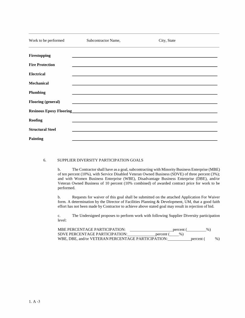
Work to be performed Subcontractor Name, City, State
Firestopping
Fire Protection
Electrical
Mechanical
Plumbing
Flooring (general)
Resinous Epoxy Flooring
Roofing
Structural Steel
Painting
6. SUPPLIER DIVERSITY PARTICIPATION GOALS
b. The Contractor shall have as a goal, subcontracting with Minority Business Enterprise (MBE)
of ten percent (10%), with Service Disabled Veteran Owned Business (SDVE) of three percent (3%);
and with Women Business Enterprise (WBE), Disadvantage Business Enterprise (DBE), and/or
Veteran Owned Business of 10 percent (10% combined) of awarded contract price for work to be
performed.
b. Requests for waiver of this goal shall be submitted on the attached Application For Waiver
form. A determination by the Director of Facilities Planning & Development, UM, that a good faith
effort has not been made by Contractor to achieve above stated goal may result in rejection of bid.
c. The Undersigned proposes to perform work with following Supplier Diversity participation
level:
MBE PERCENTAGE PARTICIPATION: percent ( %)
SDVE PERCENTAGE PARTICIPATION: percent ( %)
WBE, DBE, and/or VETERAN PERCENTAGE PARTICIPATION: percent ( %)

1.A -417
e. A Supplier Diversity Compliance Evaluation form shall be submitted with this bid for each
diverse subcontractor to be used on this project.
7. BIDDER'S ACKNOWLEDGMENTS
a. Bidder declares that he has had an opportunity to examine the site of the work and he has
examined Contract Documents therefore; that he has carefully prepared his bid upon the basis thereof;
that he has carefully examined and checked bid, materials, equipment and labor required thereunder,
cost thereof, and his figures therefore. Bidder hereby states that amount, or amounts, set forth in bid
is, or are, correct and that no mistake or error has occurred in bid or in Bidder's computations upon
which this bid is based. Bidder agrees that he will make no claim for reformation, modifications,
revisions or correction of bid after scheduled closing time for receipt of bids.
b. Bidder agrees that bid shall not be withdrawn for a period of Ninty (90) days after
sched- uled closing time for receipt of bids.
c. Bidder understands that Owner reserves right to reject any or all bids and to waive any
informalities in bidding.
d. Accompanying the bid is a bid bond, or a certified check, or an irrevocable letter of credit, or
a cashier's check payable without condition to "The Curators of the University of Missouri" which is
an amount at least equal to five percent (5%) of amount of largest possible total bid herein submitted,
including consideration of Alternates.
e. Accompanying the bid is a Bidder's Statement of Qualifications. Failure of Bidder to submit
the Bidder's Statement of Qualifications with the bid may cause the bid to be rejected. Owner does not
maintain Bidder's Statements of Qualifications on file.
f. It is understood and agreed that bid security of two (2) lowest and responsive Bidders will be
retained until Contract has been executed and an acceptable Performance Bond and Payment Bond
has been furnished. It is understood and agreed that if the bid is accepted and the undersigned fails to
execute the Contract and furnish acceptable Performance/Payment Bond as required by Contract
Documents, accompanying bid security will be realized upon or retained by Owner. Otherwise, the
bid security will be returned to the undersigned.
8. BIDDER'S CERTIFICATE
Bidder hereby certifies:
a. His bid is genuine and is not made in interest of or on behalf of any undisclosed person, firm
or corporation, and is not submitted in conformity with any agreement or rules of any group,
association or corporation.
b. He has not directly or indirectly induced or solicited any other bidder to put in a false or sham
bid.
c. He has not solicited or induced any person, firm or corporation to refrain from bidding.
d. He has not sought by collusion or otherwise to obtain for himself any advantage over any
other Bidder or over Owner.
e. He will not discriminate against any employee or applicant for employment because of race,

color, religion, sex or national origin in connection with performance of work.
f. By virtue of policy of the Board of Curators, and by virtue of statutory authority, a
preference will be given to materials, products, supplies, provisions and all other articles produced,
manufactured, mined or grown within the State of Missouri. By virtue of policy of the Board of
Curators, preference will also be given to all Missouri firms, corporations, or individuals, all as
more fully set forth in "Information For Bidders."
9. BIDDER'S SIGNATURE
Note: All signatures shall be original; not copies, photocopies, stamped, etc.
Authorized Signature Date
Printed Name Title
Company Name
Mailing Address
City, State, Zip
Phone No. Federal Employer ID No.
Fax No. E-Mail Address
Circle one: Individual Partnership Corporation Joint Venture
If a corporation, incorporated under the laws of the State of
Licensed to do business in the State of Missouri? yes no
(Each Bidder shall complete bid form by manually signing on the proper signature line above and
supplying required information called for in connection with the signature. Information is necessary for
proper preparation of the Contract, Performance Bond and Payment Bond. Each Bidder shall supply
information called for in accompanying "Bidder's Statement of Qualifications.")
END OF
SECTION
1-A.5

THIS PAGE INTENTIONALLY LEFT BLANK
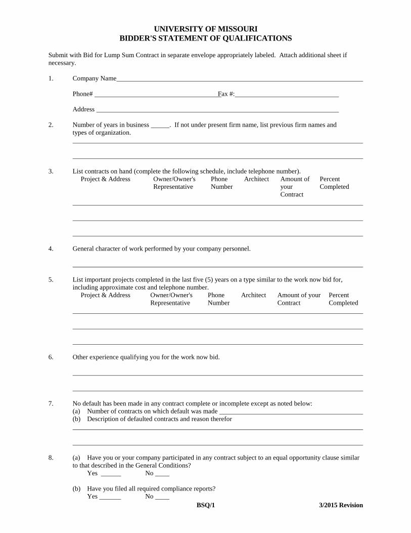
UNIVERSITY OF MISSOURI BIDDER'S STATEMENT OF QUALIFICATIONS Submit with Bid for Lump Sum Contract in separate envelope appropriately labeled. Attach additional sheet if necessary. 1. Company Name Phone# Fax #: Address 2. Number of years in business . If not under present firm name, list previous firm names and types of organization. 3. List contracts on hand (complete the following schedule, include telephone number).
Project & Address Owner/Owner's Representative
Phone Number
Architect Amount of your Contract
Percent Completed
4. General character of work performed by your company personnel. 5. List important projects completed in the last five (5) years on a type similar to the work now bid for,
including approximate cost and telephone number. Project & Address Owner/Owner's
Representative Phone Number
Architect Amount of your Contract
Percent Completed
6. Other experience qualifying you for the work now bid. 7. No default has been made in any contract complete or incomplete except as noted below: (a) Number of contracts on which default was made (b) Description of defaulted contracts and reason therefor 8. (a) Have you or your company participated in any contract subject to an equal opportunity clause similar
to that described in the General Conditions? Yes No (b) Have you filed all required compliance reports? Yes No BSQ/1 3/2015 Revision
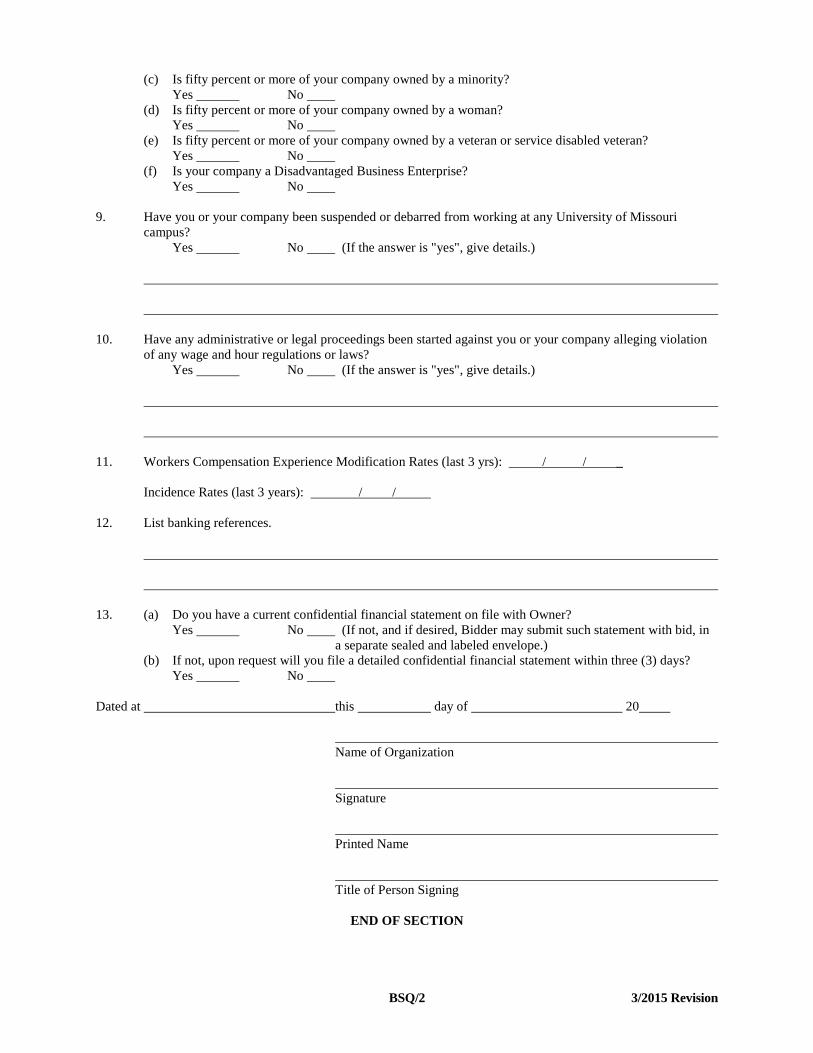
(c) Is fifty percent or more of your company owned by a minority? Yes No (d) Is fifty percent or more of your company owned by a woman? Yes No (e) Is fifty percent or more of your company owned by a veteran or service disabled veteran? Yes No (f) Is your company a Disadvantaged Business Enterprise? Yes No 9. Have you or your company been suspended or debarred from working at any University of Missouri
campus? Yes No (If the answer is "yes", give details.) 10. Have any administrative or legal proceedings been started against you or your company alleging violation
of any wage and hour regulations or laws? Yes No (If the answer is "yes", give details.) 11. Workers Compensation Experience Modification Rates (last 3 yrs): / / _ Incidence Rates (last 3 years): / / 12. List banking references. 13. (a) Do you have a current confidential financial statement on file with Owner? Yes No (If not, and if desired, Bidder may submit such statement with bid, in
a separate sealed and labeled envelope.) (b) If not, upon request will you file a detailed confidential financial statement within three (3) days? Yes No Dated at this day of 20 Name of Organization Signature Printed Name Title of Person Signing END OF SECTION
BSQ/2 3/2015 Revision

SD/1
SUPPLIER DIVERSITY COMPLIANCE EVALUATION FORM This form shall be completed by Bidders and submitted with the Bidder's Statement of Qualifications form for each diverse firm who will function as a subcontractor on the contract. The undersigned submits the following data with respect to this firm's assurance to meet the goal for Supplier Diversity participation. I. Project:
II. Name of General Contractor: III. Name of Diverse Firm:
Address:
Phone No.: Fax No.:
Status (check one) MBE _____ WBE _____ Veteran_____ Service Disabled Veteran______ DBE______ IV. Describe the subcontract work to be performed. (List Base Bid work and any Alternate work separately):
Base Bid:
V. Dollar amount of contract to be subcontracted to the Diverse firm:
Base Bid:
Alternate(s), (Identify separately):
VI. Is the proposed subcontractor listed in the Directory of M/W/DBE Vendors, Directory of Serviced Disabled
Veterans and/or the Directory of Veterans maintained by the State of Missouri?
Yes ______ No ______

SD/2
Is the proposed subcontractor certified as a diverse supplier by any of the following: federal government agencies, state agencies, State of Missouri city or county government agencies, Minority and/or WBE certifying agencies?
Yes ______ No ______ If yes, please provide details and attach
a copy of the certification.
Does the proposed subcontractor have a signed document from their attorney certifying the Supplier as a Diverse and meeting the 51% owned and committed requirement?
Yes ______ No ______ If yes, please attach letter.
Signature: ________ Name: Title: Date:

SD/3
APPLICATION FOR WAIVER This form shall be completed and submitted with the Bidder's Statement of Qualifications. Firms wishing to be considered for award are required to demonstrate that a good faith effort has been made to include diverse suppliers. This form will be used to evaluate the extent to which a good faith effort has been made. The undersigned submits the following data with respect to the firm's efforts to meet the goal for Supplier Diversity Participation. 1. List pre-bid conferences your firm attended where Supplier Diversity requirements were discussed.
2. Identify advertising efforts undertaken by your firm which were intended to recruit potential diverse subcontractors for
various aspects of this project. Provide names of newspapers, dates of advertisements and copies of ads that were run.
3. Note specific efforts to contact in writing those diverse suppliers capable of and likely to participate as subcontractors
for this project.
4. Describe steps taken by your firm to divide work into areas in which diverse suppliers/contractors would be capable of
performing.
5. What efforts were taken to negotiate with prospective diverse suppliers/contractors for specific sub-bids? Include the
names, addresses, and telephone numbers of diverse suppliers/contractors contacted, a description of the information given to diverse suppliers/contractors regarding plans and specifications for the assigned work, and a statement as to why additional agreements were not made with diverse suppliers/contractors.
6. List reasons for rejecting a diverse supplier/contractor which has been contacted.

SD/4
8. Describe the follow-up contacts with diverse suppliers/contractors made by your firm after the initial solicitation.
9. Describe the efforts made by your firm to provide interested diverse suppliers/contractors with sufficiently detailed information about the plans, specifications and requirements of the contract.
10. Describe your firm's efforts to locate diverse suppliers/contractors.
Based on the above stated good faith efforts made to include supplier diversity, the bidder hereby requests that the original supplier diversity percentage goal be waived and that the percentage goal for this project be set at ________ percent.
The undersigned hereby certifies, having read the answers contained in the foregoing Application for Waiver, that they are true and correct to the best of his/her knowledge, information and belief.
Signature
Name
Title
Company
Date

SD/5
AFFIDAVIT
"The undersigned swears that the foregoing statements are true and correct and include all material information necessary to identify and explain the operation of ____________________________ ____________________(name of firm) as well as the ownership thereof. Further, the undersigned agrees to provide through the prime contractor or directly to the Contracting Officer current, complete and accurate information regarding actual work performed on the project, the payment therefore and any proposed changes, if any, of the project, the foregoing arrangements and to permit the audit and examination of books, records and files of the named firm. Any material misrepresentation will be grounds for terminating any contract which may be awarded and for initiating action under federal or state laws concerning false statements."
Note - If, after filing this information and before the work of this firm is completed on the contract covered by this regulation, there is any significant change in the information submitted, you must inform the Director of Facilities Planning and Development of the change either through the prime contractor or directly. Signature Name Title Date Corporate Seal (where appropriate) Date State of County of On this _______________________________________ day of _________________________________________, 19 ,
before me appeared (name) __________________________________________________ to me personally known, who, being
duly sworn, did execute the foregoing affidavit, and did state that he or she was properly authorized by (name of firm)
to execute the affidavit and did so as his or her own free act and deed. (Seal) Notary Public Commission expires

THIS PAGE LEFT BLANK INTENTIONALLY
SD/6
AFFIDAVIT FOR AFFIRMATIVE ACTION
State of Missouri )
) ss. County of ) _______________________________________________________________________ first being duly sworn on his/her oath states: that he/she is the (sole proprietor, partner, or officer) of __________________________________________________ _______________________ a (sole proprietorship, partnership, corporation), and as such (sole proprietor, partner, or officer) is duly authorized to make this affidavit on behalf of said (sole proprietorship, partnership, corporation); that under the contract known as "___________________________________________________________________________________________" Project No. ________________ less than 50 persons in the aggregate will be employed and therefore, the applicable Affirmative Action requirements as set forth in the "Nondiscrimination in Employment Equal Opportunity," Supplemental Special Conditions, and Article 13 in the General Conditions do not apply.
Subscribed and sworn before me this _______________ day of ___________________________, 19________. My commission expires ___________________________________________________________, 19________.

THIS PAGE LEFT BLANK INTENTIONALLY

SD/7
CERTIFYING SUPPLIER DIVERSITYAGENCIES Diverse firms are defined in General Conditions Articles 1.1.7 and those businesses must be certified as disadvantaged by an approved agency. The Bidder is responsible for obtaining information regarding the certification status of a firm. A list of certified firms may be obtained by contacting the agencies listed below. Any firm listed as disadvantaged by any of the following agencies will be classified as a diverse firm by the Owner. St. Louis Development Corporation 1015 Locust St. Louis, MO 63101 314/622-3400; 314/622-3413 (Fax) CONTACT: Minority Business Development Manager Metro 707 North First Street St. Louis, MO 63102-2595 314/982-1400; 314/982-1558 (Fax) CONTACT: Disadvantaged Business Enterprise Coordinator St. Louis Minority Business Council 308 North 21st St., 7th Floor St. Louis, MO 63101 314/241-1143; 314/241-1073 (Fax) CONTACT: Executive Director U.S. Small Business Administration - St. Louis, MO 8(a) Contractors, Minority Small Business 1222 Spruce Street, Suite 10.103 St. Louis, MO 63101 314/539-6600; 202/481-6565 (Fax) CONTACT: Business Opportunity Specialist Lambert St. Louis International Airport 11495 Navaid Bridgeton, MO 63044 314/551-5000; 314/551-5013 (Fax) CONTACT: Program Specialist City of Kansas City, Missouri Human Relations Department, MBE/WBE Division 4th Floor, City Hall 414 E. 12th Street Kansas City, MO 64106 816/513-1836; 816/513-1805 (Fax) CONTACT: Minority Business Specialist Mid America Minority Development Council 7777 Admiral Boulevard Kansas City, MO 64106 816/221-4200; 816/221-4212 (Fax) CONTACT: President
U.S. Small Business Administration - Kansas City, MO 8(a) Contractors, Minority Small Business 1000 Walnut, Suite 500 Kansas City, MO 64106 816/426-4900; 816/426-4939 (Fax) CONTACT: Business Opportunity Specialist Missouri Department of Transportation Division of Construction P.O. Box 270 Jefferson City, MO 65102 573/751-6801; 573/526-5640-6555 (Fax) CONTACT: Disadvantaged Business Enterprise Coordinator Illinois Department of Transportation MBE/WBE Certification Section 2300 Dirksen Parkway Springfield, IL 62764 217/782-5490; 217/785-1524 (Fax) CONTACT: Certification Manager State of Missouri-Office of Administration Office of Supplier & Workforce Diversity P.O. Box 809 Jefferson City, MO 65102 573/751-8130; 573/522-8078 (Fax) CONTACT: MBE/WBE Certification Coordinator

THIS PAGE LEFT BLANK INTENTIONALLY

SD/8
Minority Newspapers Dos Mundos Bilingual Newspaper
902A Southwest Blvd. Kansas City, MO 64108 816-221-4747 www.dosmundos.com
Kansas City Hispanic News 2918 Southwest Blvd. Kansas City, MO 64108 816/472-5246 www.kchispanicnews.com The Kansas City Globe
615 E. 29th Street Kansas City, MO 64109 816-531-5253 www.thekcglobe.com/about_us.php
St. Louis American
4144 Lindell St. Louis, MO 63108 314-533-8000 www.stlamerican.com
St. Louis Chinese American News
1766 Burns Ave, Suite 201 St. Louis, MO 63132 314-432-3858 www.scannews.com
St. Louis Business Journal 815 Olive St., Suite 100 St. Louis, MO 63101 314-421-6200 www.bizjournal.com/stlouis Kansas City Business Journal 1100 Main Street, Suite 210 Kansas City, MO 64105 816-421-5900 www.bizjournals.com/kansascity

THIS PAGE LEFT BLANK INTENTIONALLY

SD/9
AFFIDAVIT OF SUPPLIER DIVERSITY PARTICIPATION
The apparent low Bidder shall complete and submit this form within 48 hours of bid opening for each Diverse firm that will participate on the contract.
1. Diverse Firm:
Contact Name:
Address:
Phone No.: E-Mail:
Status (check one) MBE � WBE � Veteran � Service Disabled Veteran � DBE �If MBE, Certified as (circle one): 1) Black American 2) Hispanic American 3) Native American 4) Asian American
2. Is the proposed diverse firm certified by an approved agency [see IFB article 15]? Yes � No �
Agency: [attach copy of certification authorization from agency]
Certification Number:
3. Diverse firm scope work and bid/contract dollar amount of participation (List Base Bid and Alternate work separately). The final Dollar amount will be determined at substantial completion:
Scope of Work Bid/Contract Amount Final Dollar Amount Base Bid
Alternate #1
Alternate #2
Alternate #3
Alternate #4
Alternate #5
Alternate #6
The undersigned certifies that the information contained herein (i.e. Scope of Work and Bid/Contract Amount) is true and correct to the best of their knowledge, information and belief.
General Contractor: Diverse Firm:
Signature: Signature:
Name: Name:
Title: Title:
Date: Date:
The undersigned certifies that the information contained herein (i.e. Scope of Work and Final Dollar Amount) is true and correct to the best of their knowledge, information and belief. If the Final Dollar Amount is different than the Bid/Contract Amount, then attach justification for the difference. . Contractor: Diverse Firm:
Signature: Signature:
Name: Name:
Title: Title:
Date: Date:

THIS PAGE LEFT BLANK INTENTIONALLY

IFB/1 04/18
University of Missouri INFORMATION FOR BIDDERS Page No. 1. Contract Documents ........................................................................................................................................................... IFB/1 2. Bidder's Obligation ............................................................................................................................................................ IFB/1 3. Interpretation of Documents .............................................................................................................................................. IFB/1 4. Bids .................................................................................................................................................................................... IFB/1 5. Modification and Withdrawal of Bids ................................................................................................................................ IFB/2 6. Signing of Bids .................................................................................................................................................................. IFB/2 7. Bid Security ....................................................................................................................................................................... IFB/2 8. Bidder’s Statement of Qualifications ................................................................................................................................. IFB/2 9. Award of Contract .............................................................................................................................................................. IFB/2 10. Contract Execution ............................................................................................................................................................ IFB/2 11. Contract Security ............................................................................................................................................................... IFB/3 12. Time of Completion ........................................................................................................................................................... IFB/3 13. Number of Contract Documents ........................................................................................................................................ IFB/3 14. Missouri Products and Missouri Firms .............................................................................................................................. IFB/3 15. Supplier Diversity .............................................................................................................................................................. IFB/3 16. List of Subcontractors ........................................................................................................................................................ IFB/5 1. Contract Documents 1.1 Drawings, specifications, and other contract documents, pursuant to work which is to be done, may be obtained shown in the Advertisement for Bids and Special Conditions. 2. Bidder Obligations 2.1 Before submitting bids each bidder shall carefully examine the drawings and specifications and related contract documents, visit site of work and fully inform themselves as to all existing conditions, facilities, restrictions and other matters which can affect the work or the cost thereof. 2.2 Each bidder shall include in their bid the cost of all work and materials required to complete the contract in a first-class manner as hereinafter specified. 2.3 Failure or omission of any bidder to receive or examine any form, instrument, addendum, or other document, or to visit the site and acquaint themselves with existing conditions, shall in no way relieve them from any obligation with respect to their bid or contract, and no extra compensation will be allowed by reason of any thing or matter concerning which bidder should have fully informed themselves prior to bidding. 2.4 Submission of bids shall be deemed acceptance of the above obligations and each and every obligation required to be performed by all of the contract documents in the event the bid is accepted. 3. Interpretation of Documents 3.1 If any prospective bidder is in doubt as to the true meaning of any part of the drawings and specifications or contract documents, they shall submit a written request to the Architect for an interpretation. 3.2 Requests for such interpretations shall be delivered to the Architect at least one (1) week prior to time for receipt of bids.
3.3 Bids shall be based only on interpretations issued in the form of addenda mailed to each person who is on the Architect's record as having received a set of the contract documents. 4. Bids 4.1 Bids shall be received separately or in combination as shown in and required by the Bid for Lump Sum contract. Bids will be completed so as to include insertion of amounts for alternate bids, unit prices and cost accounting data. 4.2 Bidders shall apportion each base bid between various phases of the work, as stipulated in the Bid for Lump Sum contract. All work shall be done as defined in the specifications and as indicated on the drawings. 4.3 Bids shall be presented in sealed envelopes which shall be plainly marked "Bids for (indicate name of project from cover sheet)”, and mailed or delivered to the building and room number specified in the Advertisement for Bids. Bidders shall be responsible for actual delivery of bids during business hours, and it shall not be sufficient to show that a bid was mailed in time to be received before scheduled closing time for receipt of bids, nor shall it be sufficient to show that a bid was somewhere in a university facility. 4.4 The bidder's price shall include all federal sales, excise, and similar taxes, which may be lawfully assessed in connection with their performance of work and purchase of materials to be incorporated in the work. City & State taxes shall not be included as defined within Article 3.16 of the General Conditions for Construction Contract included in the contract documents. 4.5 Bids shall be submitted on a single bid form, furnished by the Owner or Architect. Do not remove the bid form from the specifications. 4.6 No bidder shall stipulate in their bid any conditions not contained in the bid form.
IFB/2 04/18
4.7 The Owner reserves the right to waive informalities in bids and to reject any or all bids. 5. Modification and Withdrawal of Bids 5.1 The bidder may withdraw their bid at any time before the scheduled closing time for receipt of bids, but no bidder may withdraw their bid after the scheduled closing time for receipt of bids. 5.2 Only telegrams, letters and other written requests for modifications or correction of previously submitted bids, contained in a sealed envelope which is plainly marked "Modification of Bid on (name of project on cover sheet),” which are addressed in the same manner as bids, and are received by Owner before the scheduled closing time for receipt of bids will be accepted and bids corrected in accordance with such written requests. 6. Signing of Bids 6.1 Bids which are signed for a partnership shall be manually signed in the firm name by at least one partner, or in the firm name by Attorney-in-Fact. If signed by Attorney-in-Fact there should be attached to the bid, a Power of Attorney evidencing authority to sign the bid dated the same date as the bid and executed by all partners of the firm. 6.2 Bids that are signed for a corporation shall have the correct corporate name thereon and the signature of an authorized officer of the corporation manually written below corporate name. Title of office held by the person signing for the corporation shall appear below the signature of the officer. 6.3 Bids that are signed by an individual doing business under a firm name, shall be manually signed in the name of the individual doing business under the proper firm name and style. 6.4 Bids that are signed under joint venture shall be manually signed by officers of the firms having authority to sign for their firm. 7. Bid Security 7.1 Each bid shall be accompanied by a bid bond, certified check, or cashier's check, acceptable to and payable without condition to The Curators of the University of Missouri, in an amount at least equal to five percent (5%) of bidder's bid including additive alternates. 7.2 Bid security is required as a guarantee that bidder will enter into a written contract and furnish a performance bond within the time and in form as specified in these specifications; and if successful bidder fails to do so, the bid security will be realized upon or retained by the Owner. The apparent low bidder shall notify the Owner in writing within 48 hours (2 work days) of the bid opening of any circumstance that may affect the bid security including, but not limited to, a bidding error. This notification will not guarantee release of the bidder’s security and/or the bidder from the Bidder’s Obligations. 7.3 If a bid bond is given as a bid security, the amount of the bond may be stated as an amount equal to at least five percent (5%) of the bid, including additive alternates,
described in the bid. The bid bond shall be executed by the bidder and a responsible surety licensed in the State of Missouri with a Best’s rating of no less than A-/XI. 7.4 It is specifically understood that the bid security is a guarantee and shall not be considered as liquidated damages for failure of bidder to execute and deliver their contract and performance bond, nor limit or fix bidder's liability to Owner for any damages sustained because of failure to execute and deliver the required contract and performance bond. 7.5 Bid security of the two (2) lowest and responsive Bidders will be retained by the Owner until a contract has been executed and an acceptable bond has been furnished, as required hereby, when such bid security will be returned. Surety bid bonds of all other bidders will be destroyed and all other alternative forms of bid bonds will be returned to them within ten (10) days after Owner has determined the two (2) lowest and responsive bids. 8. Bidder's Statement of Qualifications 8.1 Each bidder submitting a bid shall present evidence of their experience, qualifications, financial responsibility and ability to carry out the terms of the contract by completing and submitting with their bid the schedule of information set forth in the form furnished in the bid form. 8.2 Such information, a single copy required in a separate sealed envelope, will be treated as confidential information by the Owner, within the meaning of Missouri Statue 610.010. 8.3 Bids not accompanied with current Bidder's Statement of Qualifications may be rejected. 9. Award of Contract 9.1 The Owner reserves the right to let other contracts in connection with the work, including, but not by way of limitation, contracts for furnishing and installation of furniture, equipment, machines, appliances, and other apparatus. 9.2 In awarding the contract, the Owner may take into consideration the bidder's, and their subcontractor’s, ability to handle promptly the additional work, skill, facilities, capacity, experience, ability, responsibility, previous work, financial standing of bidder, and the bidder’s ability to provide the required bonds and insurance; quality, efficiency and construction of equipment proposed to be furnished; period of time within which equipment is proposed to be furnished and delivered; success in achieving the specified Supplier Diversity goal, or demonstrating a good faith effort as described in Article 15; necessity of prompt and efficient completion of work herein described, and the bidder’s status as suspended or debarred. Inability of any bidder to meet the requirements mentioned above may be cause for rejection of their bid. 10. Contract Execution 10.1 The Contractor shall submit within fifteen (15) days from receipt of notice, the documents required in Article 9 of the General Conditions for Construction Contract included in the contract documents.

IFB/3 04/18
10.2 No bids will be considered binding upon the Owner until the documents listed above have been furnished. Failure of Contractor to execute and submit these documents within the time period specified will be treated, at the option of the Owner, as a breach of the bidder's bid security under Article 7 and the Owner shall be under no further obligation to Bidder. 11. Contract Security 11.1 When the Contract sum exceeds $50,000, the Contractor shall procure and furnish a Performance bond and a Payment bond in the form prepared by Owner. Each bond shall be in the amount equal to one hundred percent (100%) of the contract sum, as well as adjustments to the Contract Sum. The Performance Bond shall secure and guarantee Contractor’s faithful performance of this Contract, including but not limited to Contractor’s obligation to correct defects after final payment has been made as required by the Contract Documents. The Payment Bond shall secure and guarantee payment of all persons performing labor on the Project under this Contract and furnishing materials in connection with this Contract. These Bonds shall be in effect through the duration of the Contract plus the Guaranty Period as required by the Contract Documents. 11.2 The bonds required hereunder shall be meet all requirements of Article 11 of the General Conditions for Construction Contract included in the contract documents. 11.3 If the surety of any bond furnished by Contractor is declared bankrupt or becomes insolvent or its right to conduct business in the State of Missouri is terminated, or it ceases to meet the requirements of this Article 11, Contractor shall within ten (10) days substitute another bond and surety, both of which must be acceptable to Owner. If Contractor fails to make such substitution, Owner may procure such required bonds on behalf of Contractor at Contractor’s expense. 12. Time of Completion 12.1 Contractors shall agree to commence work within five (5) days of the date "Notice to Proceed" is received from the Owner, and the entire work shall be completed by the completion date specified or within the number of consecutive calendar days stated in the Special Conditions. The duration of the construction period, when specified in consecutive calendar days, shall begin when the contractor receives notice requesting the documents required in Article 9 of the General Conditions for Construction Contract included in the contract documents. 13. Number of Contract Documents 13.1 The Owner will furnish the Contractor a copy of the executed contract and performance bond. 13.2 The Owner will furnish the Contractor the number of copies of complete sets of drawings and specifications for the work, as well as, clarification and change order drawings pertaining to change orders required during construction as set forth in the Special Conditions. 14. Missouri Products and Missouri Firms 14.1 The Curators of the University of Missouri have adopted a policy which is binding upon all employees and departments of the University of Missouri, and which by contract, shall be binding upon independent contractors and
subcontractors with the University of Missouri whereby all other things being equal, and when the same can be secured without additional cost over foreign products, or products of other states, a preference shall be granted in all construction, repair and purchase contracts, to all products, commodities, materials, supplies and articles mined, grown, produced and manufactured in marketable quantity and quality in the State of Missouri, and to all firms, corporations or individuals doing business as Missouri firms, corporations or individuals. Each bidder submitting a bid agrees to comply with, and be bound by the foregoing policy. 15. SUPPLIER DIVERSITY 15.1 Award of Contract The Supplier Diversity participation goal for this project is stated on the Bid for Lump Sum Contract Form, and the Owner will take into consideration the bidder's success in achieving the Supplier Diversity participation goal in awarding the contract. Inability of any bidder to meet this requirement may be cause for rejection of their bid. The University will grant a three (3) point bonus preference to a Missouri based, certified Service Disabled Veteran Enterprise (SDVE) bidder as defined in Article 1 – (Supplier Diversity Definitions) of the General Conditions of the Contract for Construction included in the contract documents. The three percent (3%) goal can be met, and the bonus points obtained, by a qualified SDVE vendor and/or through the use of qualified subcontractors or suppliers that provide at least three percent (3%) of the total contract value. 15.2 List of Supplier Diversity Firms 15.2.1 The bidder shall submit as part of their bid a list of diverse firms performing as contractor, subcontractors, and/or suppliers. The list shall specify the single designated diverse firm name and address. If acceptance or non-acceptance of alternates will affect the designation of a subcontractor, provide information for each affected category. 15.2.2 Failure to include a complete list of diverse firms may be grounds for rejection of the bid. 15.2.3 The list of diverse firms shall be submitted in addition to any other listing of subcontractors required in the Bid for Lump Sum Contract Form. 15.3 Supplier Diversity Percentage Goal The bidder shall have a minimum goal of subcontracting with diverse contractors, subcontractors, and suppliers, the percent of contract price stated in the Supplier Diversity goal paragraph of the Bid for Lump Sum Contract Form. . 15.4 Supplier Diversity Percent Goal Computation 15.4.1 The total dollar value of the work granted to the diverse firms by the successful bidder is counted towards the applicable goal of the entire contract, unless otherwise noted below. 15.4.2 The bidder may count toward the Supplier Diversity goal only expenditures to diverse firms that perform a commercially useful function in the work of a contract. A diverse firm is considered to perform a commercially useful function when it is responsible for executing a distinct element of the work and carrying out its responsibilities by

IFB/4 04/18
actually performing, managing and supervising the work involved. A bidder that is a certified diverse firm may count as 100% of the contract towards the Supplier Diversity goal. For projects with separate MBE, SDVE, and WBE/Veteran /DBE goals, a MBE firm bidding as the prime bidder is expected to obtain the required SDVE, and WBE/Veteran/ DBE participation; a WBE or Veteran or DBE firm bidding as the prime bidder is expected to obtain the required MBE and SDVE participation and a SDVE firm bidding as the prime bidder is expected to obtain the required MBE, and WBE/Veteran/ DBE participation. 15.4.3 When a MBE, WBE, Veteran Business Enterprise, DBE, or SDVE performs work as a participant in a joint venture, only the portion of the total dollar value of the contract equal to the distinct, clearly defined portion of the work of the contract that the MBE, WBE, Veteran Business Enterprise, DBE, or SDVE performs with its own forces shall count toward the MBE, WBE, Veteran Business Enterprise, DBE, or SDVE individual contract percentages. 15.4.4 The bidder may count toward its Supplier Diversity goal expenditures for materials and supplies obtained from diverse suppliers and manufacturers, provided the diverse firm assumes the actual and contractual responsibility for the provision of the materials and supplies. 15.4.4.1 The bidder may count its entire expenditure to a diverse manufacturer. A manufacturer shall be defined as an individual or firm that produces goods from raw materials or substantially alters them before resale. 15.4.4.2 The bidder may count its entire expenditure to diverse suppliers that are not manufacturers provided the diverse supplier performs a commercially useful function as defined above in the supply process. 15.4.4.3 The bidder may count 25% of its entire expenditures to diverse firms that do not meet the definition of a subcontractor, a manufacturer, nor a supplier. Such diverse firms may arrange for, expedite, or procure portions of the work but are not actively engaged in the business of performing, manufacturing, or supplying that work. 15.4.5 The bidder may count toward the Supplier Diversity goal that portion of the total dollar value of the work awarded to a certified joint venture equal to the percentage of the ownership and control of the diverse partner in the joint venture. 15.4.6 On projects with separate MBE and WBE/Veteran/DBE goals, the Owner may allow MBE participation provided in excess of the MBE goal to be counted towards the WBE/Veteran /DBE goal. 15.5 Certification by Bidder of Diverse Firms 15.5.1 The bidder shall submit with its bid the information requested in the "Supplier Diversity Compliance Evaluation Form" for every diverse firm the bidder intends to award work to on the contract. 15.5.2 Diverse firms are defined in Article 1 – (Supplier Diversity Definitions) of the General Conditions of the Contract for Construction included in the contract documents,
and as those businesses certified as disadvantaged by an approved agency. The bidder is responsible for obtaining information regarding the certification status of a firm. A list of certified firms may be obtained by contacting the agencies listed in the proposal form document “Supplier Diversity Certifying Agencies”. Any firm listed as disadvantaged by any of the identified agencies will be classified as a diverse firm by the Owner. 15.5.3 Bidders are urged to encourage their prospective diverse contractors, subcontractors, joint venture participants, team partners, and suppliers who are not currently certified to obtain certification from one of the approved agencies. 15.6 Supplier Diversity Participation Waiver 15.6.1 The bidder is required to make a good faith effort to locate and contract with diverse firms. If a bidder has made a good faith effort to secure the required diverse firms and has failed, the bidder shall submit with the bid, the information requested in "Application for Supplier Diversity Participation Waiver." The Contracting Officer will review the bidder's actions as set forth in the bidder's "Application for Waiver" and any other factors deemed relevant by the Contracting Officer to determine if a good faith effort has been made to meet the applicable percentage goal. If the bidder is judged not to have made a good faith effort, the bid may be rejected. Bidder's who demonstrate that they have made a good faith effort to include Supplier Diversity participation may be awarded the contract regardless of the percent of Supplier Diversity participation, provided the bid is otherwise acceptable and is determined to be the best bid. 15.6.2 To determine good faith effort of the bidder, the Contracting Officer may evaluate factors including, but not limited to, the following: 15.6.2.1 The bidder’s attendance at pre-proposal meetings scheduled to inform bidders and diverse firms of contracting and subcontracting opportunities and responsibilities associated with Supplier Diversity participation. 15.6.2.2 The bidder’s advertisements in general circulation trade association, and diverse (minority) focused media concerning subcontracting opportunities. 15.6.2.3 The bidder’s written notice to specific diverse firms that their services were being solicited in sufficient time to allow for their effective participation. 15.6.2.4 The bidder’s follow-up attempts to the initial solicitation(s) to determine with certainty whether diverse firms were interested. 15.6.2.5 The bidder’s efforts to divide the work into packages suitable for subcontracting to diverse firms. 15.6.2.6 The bidder’s efforts to provide interested diverse firms with sufficiently detailed information about the drawings, specific actions and requirements of the contract, and clear scopes of work for the firms to bid on.

IFB/5 04/18
15.6.2.7 The bidder’s efforts to solicit for specific sub-bids from diverse firms in good faith. Documentation should include names, addresses, and telephone numbers of firms contacted a description of all information provided the diverse firms, and an explanation as to why agreements were not reached. 15.6.2.8 The bidder's efforts to locate diverse firms not on the directory list and assist diverse firms in becoming certified as such. 15.6.2.9 The bidder's initiatives to encourage and develop participation by diverse firms. 15.6.2.10 The bidder’s efforts to help diverse firms overcome legal or other barriers impeding the participation of diverse firms in the construction contract. 15.6.2.11 The availability of diverse firms and the adequacy of the bidder's efforts to increase the participation of such business provided by the persons and organizations consulted by the bidder. 15.7 Submittal of Forms 15.7.1 The bidder will include the Supplier Diversity Compliance Evaluation Form(s), or the Application for Waiver and other form(s) as required above in the envelope containing the "Bidder's Statement of Qualifications", see Article 8. 15.8 Additional Bid/Proposer Information 15.8.1 The Contracting Officer reserves the right to request additional information regarding Supplier Diversity participation and supporting documentation from the apparent low bidder. The bidder shall respond in writing to the Contracting Officer within 24 hours (1 work day) of a request. 15.8.2 The Contracting Officer reserves the right to request additional information after the bidder has responded to prior 24 hour requests. This information may include follow up and/or clarification of the information previously submitted. 15.8.3 The Owner reserves the right to consider additional diverse subcontractor and supplier participation submitted by the bidder after bids are opened under the provisions within these contract documents that describe the Owner’s right to accept or reject subcontractors including, but not limited to, Article 16 below. The Owner may elect to waive the good faith effort requirement if such additional participation achieves the Supplier Diversity goal. 15.8.4 The Bidder shall provide the Owner information related to the Supplier Diversity participation included in the bidder’s proposal, including, but is not limited to, the complete Application for Waiver, evidence of diverse certification of participating firms, dollar amount of participation of diverse firms, information supporting a good faith effort as described in Article 15.6 above, and a list of all diverse firms that submitted bids to the Bidder with the diverse firm’s price and the name and the price of the firm awarded the scope of work bid by the diverse firm.
16. List of Subcontractors 16.1 If a list of subcontractors is required on the Bid for Lump Sum Contract Form, the bidders shall list the name, city and state of the firm(s) which will accomplish that portion of the contract requested in the space provided. This list is separate from both the list of diverse firms required in Article 15.2, and the complete list of subcontractors required in Article 10.1 of this document. Should the bidder choose to perform any of the listed portions of the work with its own forces, the bidder shall enter its own name, city and state in the space provided. If acceptance or non-acceptance of alternates will affect the designation of a subcontractor, the bidder shall provide that information on the bid form. 16.2 Failure of the bidder to supply the list of subcontractors required or the listing of more than one subcontractor for any category without designating the portion of the work to be performed by each, shall be grounds for the rejection of the bid. The bidder can petition the Owner to change a listed subcontractor within 48 hours of the bid opening. The Owner reserves the right to make the final determination on a petition to change a subcontractor. The Owner will consider factors such as clerical and mathematical bidding errors, listed subcontractor’s inability to perform the work for the bid used, etc. Any request to change a listed subcontractor shall include at a minimum, contractor’s bid sheet showing tabulation of the bid; all subcontractor bids with documentation of the time they were received by the contractor; and a letter from the listed subcontractor on their letterhead stating why they cannot perform the work if applicable. The Owner reserves the right to ask for additional information. 16.3 Upon award of the contract, the requirements of Article 10 of this document and Article 5 of the General Conditions of the Contract for Construction included in the contract documents will apply.

THIS PAGE INTENTIONALLY LEFT BLANK

University of Missouri
General Conditions
of the
Contract
for
Construction
September 2016 Edition
THIS PAGE INTENTIONALLY LEFT BLANK
TABLE OF ARTICLES PAGE
1. GENERAL PROVISIONS .................................................................................................................................... GC/1 1.1 Basic Definitions ............................................................................................................................................. GC/1 1.2 Specifications and Drawings ........................................................................................................................... GC/3 1.3 Required Provisions Deemed Inserted ............................................................................................................ GC/4 2. OWNER .................................................................................................................................................................. GC/4 2.1 Information and Services Required of the Owner ........................................................................................... GC/4 2.2 Owner's Right to Stop the Work ...................................................................................................................... GC/4 2.3 Owner's Right to Carry Out the Work ............................................................................................................. GC/4 2.4 Extent of Owner Rights ................................................................................................................................... GC/4 3. CONTRACTOR .................................................................................................................................................... GC/5 3.1 Contractor's Warranty ..................................................................................................................................... GC/5 3.2 Compliance with Laws, Permits, Regulations and Inspections ....................................................................... GC/5 3.3 Anti-Kickback ................................................................................................................................................. GC/6 3.4 Supervision and Construction Procedures ....................................................................................................... GC/6 3.5 Use of Site ....................................................................................................................................................... GC/7 3.6 Review of Contract Documents and Field Conditions by Contractor .............................................................. GC/8 3.7 Cleaning and Removal .................................................................................................................................... GC/8 3.8 Cutting and Patching ....................................................................................................................................... GC/8 3.9 Indemnification ............................................................................................................................................... GC/9 3.10 Patents ............................................................................................................................................................. GC/9 3.11 Materials, Labor, and Workmanship ............................................................................................................... GC/10 3.12 Approved Equal .............................................................................................................................................. GC/11 3.13 Shop Drawings, Product Data and Samples .................................................................................................... GC/11 3.14 Record Drawings ............................................................................................................................................. GC/12 3.15 Operating Instructions and Service Manual .................................................................................................... GC/13 3.16 Taxes ............................................................................................................................................................... GC/13 3.17 Contractor’s Construction Schedules .............................................................................................................. GC/14 4. ADMINISTRATION OF THE CONTRACT ..................................................................................................... GC/14 4.1 Rights of the Owner ........................................................................................................................................ GC/14 4.2 Rights of the Architect .................................................................................................................................... GC/15 4.3 Review of the Work ........................................................................................................................................ GC/15 4.4 Claims ............................................................................................................................................................. GC/15 4.5 Claims for Concealed or Unknown Conditions ............................................................................................... GC/15 4.6 Claim for Additional Cost ............................................................................................................................... GC/16 4.7 Claims for Additional Time ............................................................................................................................ GC/16 4.8 Resolution of Claims and Disputes ................................................................................................................. GC/17 4.9 Administrative Review .................................................................................................................................... GC/17 5. SUBCONTRACTORS .......................................................................................................................................... GC/18 5.1 Award of Subcontracts .................................................................................................................................... GC/18 5.2 Subcontractual Relations ................................................................................................................................. GC/18 5.3 Contingent Assignment of Subcontract ........................................................................................................... GC/18 6. SEPARATE CONTRACTS AND COOPERATION .......................................................................................... GC/18 7. CHANGES IN THE WORK ................................................................................................................................. GC/19
7.1 Change Orders ................................................................................................................................................ GC/19 7.2 Construction Change Directive ....................................................................................................................... GC/20 7.3 Overhead and Profit ........................................................................................................................................ GC/20 7.4 Extended General Conditions ......................................................................................................................... GC/21 7.5 Emergency Work ............................................................................................................................................ GC/21

8. TIME ...................................................................................................................................................................... GC/21 8.1 Progress and Completion ................................................................................................................................ GC/21 8.2 Delay in Completion ....................................................................................................................................... GC/21 8.3 Liquidated Damages ........................................................................................................................................ GC/22 9. PAYMENTS AND COMPLETION ..................................................................................................................... GC/23 9.1 Commencement, Prosecution and Completion ................................................................................................ GC/23 9.2 Contract Sum ................................................................................................................................................... GC/24 9.3 Schedule of Values .......................................................................................................................................... GC/24 9.4 Applications for Payment ................................................................................................................................ GC/24 9.5 Approval for Payment ..................................................................................................................................... GC/25 9.6 Decisions to Withhold Approval ..................................................................................................................... GC/25 9.7 Progress Payments .......................................................................................................................................... GC/26 9.8 Failure of Payment .......................................................................................................................................... GC/26 9.9 Substantial Completion ................................................................................................................................... GC/26 9.10 Partial Occupancy or Use ................................................................................................................................ GC/26 9.11 Final Completion and Final Payment .............................................................................................................. GC/27 10. PROTECTION OF PERSONS AND PROPERTY ............................................................................................ GC/27 10.1 Safety Precautions and Programs .................................................................................................................... GC/27 10.2 Safety of Persons and Property ....................................................................................................................... GC/28 11. INSURANCE & BONDS....................................................................................................................................... GC/28 11.1 Insurance ......................................................................................................................................................... GC/28 11.2 Commercial General Liability ......................................................................................................................... GC/28 11.3 Licensed for Use Vehicle Liability .................................................................................................................. GC/29 11.4 Workers’ Compensation Insurance ................................................................................................................. GC/29 11.5 Liability Insurance General Requirements ...................................................................................................... GC/29 11.6 Builder’s Risk Insurance ................................................................................................................................. GC/30 11.7 Bonds .............................................................................................................................................................. GC/31 12. UNCOVERING AND CORRECTION OF THE WORK .................................................................................. GC/32 12.1 Uncovering of the Work .................................................................................................................................. GC/32 12.2 Correction of the Work ................................................................................................................................... GC/32 12.3 Acceptance of Nonconforming Work ............................................................................................................. GC/33 13. MISCELLANEOUS PROVISIONS ..................................................................................................................... GC/33 13.1 Written Notice ................................................................................................................................................. GC/33 13.2 Rights and Remedies ....................................................................................................................................... GC/33 13.3 Tests and Inspections ...................................................................................................................................... GC/33 13.4 Nondiscrimination in Employment Equal Opportunity ................................................................................... GC/34 13.5 Supplier Diversity Goal Program .................................................................................................................... GC/34 13.6 Wage Rates ..................................................................................................................................................... GC/34 13.7 Records ........................................................................................................................................................... GC/36 13.8 Codes and Standards ....................................................................................................................................... GC/36 13.9 General Provisions .......................................................................................................................................... GC/37 13.10Debarment and Suspension Certificate…………………………………………………………………… .... GC/37

14. TERMINATION OR SUSPENSION OF THE CONTRACT ........................................................................... GC/38
14.1 Termination by Owner for Cause .................................................................................................................... GC/38 14.2 Suspension by the Owner for Convenience .................................................................................................. GC/38 14.3 Owner’s Termination for Convenience ........................................................................................................... GC/38

THIS PAGE INTENTIONALLY LEFT BLANK

GC/1 09/16
ARTICLE 1
GENERAL PROVISIONS 1.1 Basic Definitions As used in the Contract Documents, the following terms shall have the meanings and refer to the parties designated in these definitions. 1.1.1 Owner The Curators of the University of Missouri. The Owner may act through its Board of Curators or any duly authorized committee or representative thereof. 1.1.2 Contracting Officer The Contracting Officer is the duly authorized representative of the Owner with the authority to execute contracts. Communications to the Contracting Officer shall be forwarded via the Owner's Representative. 1.1.3 Owner's Representative The Owner’s Representative is authorized by the Owner as the administrator of the Contract and will represent the Owner during the progress of the Work. Communications from the Architect to the Contractor and from the Contractor to the Architect shall be through the Owner's Representative, unless otherwise indicated in the Contract Documents. 1.1.4 Architect When the term "Architect" is used herein, it shall refer to the Architect or the Engineer specified and defined in the Contract for Construction or its duly authorized representative. Communications to the Architect shall be forwarded to the address shown in the Contract for Construction. 1.1.5 Contractor The Contractor is the person or entity with whom the Owner has entered into the Contract for Construction. The term “Contractor” means the Contractor or the Contractor’s authorized representative. 1.1.6 Subcontractor and Lower-tier Subcontractor A Subcontractor is a person or organization who has a contract with the Contractor to perform any of the Work. The term "Subcontractor" is referred to throughout the Contract Documents as if singular in number and means a Subcontractor or its authorized representative. The term "Subcontractor" also is applicable to those furnishing materials to be incorporated in the Work whether work performed is at the Owner’s site or off site, or both. A lower-tier Subcontractor is a person or organization who has a contract with a Subcontractor or another lower-tier Subcontractor to perform any of the Work at the site. Nothing contained in the Contract Documents shall create contractual relationships between the Owner or the Architect and any Subcontractor or lower-tier Subcontractor of any tier.
1.1.7 Supplier Diversity Definitions Businesses that fall into the Supplier Diversity classification shall mean an approved certified business concern which is at least fifty-one percent (51%) owned and controlled by one (1) or more diverse suppliers as described below. .1 Minority Business Enterprises (MBE) Minority Business Enterprise [MBE] shall mean an approved certified business concern which is at least fifty-one percent (51%) owned and controlled by one (1) or more minorities as defined below or, in the case of any publicly-owned business, in which at least fifty-one percent (51%) of the stock of which is owned by one (1) or more minorities as defined below, and whose management and daily business operations are controlled by one (1) or more minorities as defined herein.
.1.1 "African Americans", which includes persons having origins in any of the black racial groups of Africa.
.1.2 "Hispanic Americans", which includes persons of Mexican, Puerto Rican, Cuban, Central or South American, or other Spanish culture or origin, regardless of race.
.1.3 "Native Americans", which includes persons of American Indian, Eskimo, Aleut, or Native Hawaiian origin.
.1.4 "Asian-Pacific Americans", which includes persons whose origins are from Japan, China, Taiwan, Korea, Vietnam, Laos, Cambodia, the Philippines, Samoa, Guam, the U.S. Trust Territories of the Pacific, or the Northern Marinas.
.1.5 "Asian-Indian Americans", which includes persons whose origins are from India, Pakistan, or Bangladesh.
.2 Women Business Enterprise (WBE) Women Business Enterprise [WBE] shall mean an approved certified business concern which is at least fifty-one percent (51%) owned and controlled by one (1) or more women or, in the case of any publicly-owned business, in which at least fifty-one percent (51%) of the stock of which is owned by one (1) or more women, and whose management and daily business operations are controlled by one (1) or more women. .3 Veteran Owned Business Veteran Owned Business shall mean an approved certified business concern which is at least fifty-one percent (51%) owned and controlled by one (1) or more Veterans or, in the case of any publicly-owned business, in which at least fifty-one percent (51%) of the stock of which is owned by one (1) or more Veterans, and whose management and daily business operations are controlled by one (1) or more Veterans. Veterans must be certified by the appropriate federal agency responsible for veterans’ affairs. .4 Service Disabled Veteran Enterprise (SDVE) Service Disabled Veteran Enterprise (SDVE) shall mean a business certified by the State of Missouri Office of Administration as a Service Disabled Veteran Enterprise, which is at least fifty-one percent (51%) owned and controlled by one (1) or more Serviced Disabled Veterans or,
GC/2 09/16
in the case of any publicly-owned business, in which at least fifty-one percent (51%) of the stock of which is owned by one (1) or more Service Disabled Veterans, and whose management and daily business operations are controlled by one (1) or more Serviced Disabled Veterans. .5 Disadvantaged Business Enterprise (DBE) A Disadvantaged Business Enterprise (DBE) is a for-profit small business concern where a socially and economically disadvantaged individual owns at least 51% interest and also controls management and daily business operations. These firms can and also be referred to as Small Disadvantaged Businesses (SDB). Eligibility requirements for certification are stated in 49 CFR (Code of Federal Regulations), part 26, Subpart D. U.S. citizens that are African-Americans, Hispanics, Native Americans, Asian-Pacific and Subcontinent Asian Americans, and women are presumed to be socially and economically disadvantaged. Also recognized as DBE’s are Historically Black Colleges and Universities (HBCU) and small businesses located in Federal HUB Zones. To be regarded as economically disadvantaged, an individual must have a personal net worth that does not exceed $1.32 million. To be seen as a small business, a firm must meet Small Business Administration (SBA) size criteria (500 employees or less) and have average annual gross receipts not to exceed $22.41 million. To be considered a DBE/SDB, a small business owned and controlled by socially and/or economically disadvantaged individuals must receive DBE certification from one of the recognized Missouri state agencies to be recognized in this classification. 1.1.9 Work Work shall mean supervision, labor, equipment, tools, material, supplies, incidentals operations and activities required by the Contract Documents or reasonably inferable by Contractor therefrom as necessary to produce the results intended by the Contract Documents in a safe, expeditious, orderly, and workmanlike manner, and in the best manner known to each respective trade. 1.1.10 Approved The terms "approved", "equal to", "directed", "required", "ordered", "designated", "acceptable", "satisfactory", and similar words or phrases will be understood to have reference to action on the part of the Architect and/or the Owner's Representative. 1.1.11 Contract Documents The Contract Documents consist of (1) the executed Contract for Construction, (2) these General Conditions of the Contract for Construction, (3) any Supplemental Conditions or Special Conditions identified in the Contract for Construction, (4) the Specifications identified in the Contract for Construction, (5) the Drawings identified in the Contract for Construction, (6) Addenda
issued prior to the receipt of bids, (7) Contractor’s bid addressed to Owner, including Contractor’s completed Qualification Statement, (8) Contractor’s Performance Bond and Contractor’s Payment Bond, (9) Notice to Proceed, (10) and any other exhibits and/or post bid adjustments identified in the Contract for Construction, (11) Advertisement for Bid, (12) Information for Bidders, and (13) Change Orders issued after execution of the Contract. All other documents and technical reports and information are not Contract Documents, including without limitation, Shop Drawings, and Submittals. 1.1.12 Contract The Contract Documents form the Contract and are the exclusive statement of agreement between the parties. The Contract represents the entire and integrated agreement between the parties hereto and supersedes prior representations or agreements, either written or oral. The Contract Documents shall not be construed to create a contractual relationship of any kind between the Owner and a Subcontractor or any lower-tier Subcontractor. 1.1.13 Change Order The Contract may be amended or modified without invalidating the Contract, only by a Change Order, subject to the limitations in Article 7 and elsewhere in the Contract Documents. A Change Order is a written instrument signed by the Owner and the Contractor stating their agreement to a change in the Work, the amount of the adjustment to the Contract Sum, if any, and the extent of the adjustment to the Contract Time, if any. Agreement to any Change Order shall constitute a final settlement of all matters relating to the change in the work which is the subject of the Change Order, including, but not limited to, all direct and indirect costs associated with such change and any and all adjustments of the Contract sum, time and schedule. 1.1.14 Substantial Completion The terms “Substantial Completion” or "substantially complete" as used herein shall be construed to mean the completion of the entire Work, including all submittals required under the Contract Documents, except minor items which in the opinion of the Architect, and/or the Owner's Representative will not interfere with the complete and satisfactory use of the facilities for the purposes intended. 1.1.15 Final Completion The date when all punch list items are completed, including all closeout submittals and approval by the Architect is given to the Owner in writing. 1.1.16 Supplemental and Special Conditions The terms “Supplemental Conditions” or “Special Conditions” shall mean the part of the Contract Documents which amend, supplement, delete from, or add to these General Conditions.

GC/3 09/16
1.1.17 Day The term "day" as used in the Contract Documents shall mean calendar day unless otherwise specifically defined. 1.1.18 Knowledge. The terms “knowledge,” “recognize” and “discover,“ their respective derivatives and similar terms in the Contract Documents, as used in reference to the Contractor, shall be interpreted to mean that which the Contractor knows or should know, recognizes or should recognize and discovers or should discover in exercising the care, skill, and diligence of a diligent and prudent contractor familiar with the work. Analogously, the expression “reasonably inferable” and similar terms in the Contract Documents shall be interpreted to mean reasonably inferable by a diligent and prudent contractor familiar with the work. 1.1.19 Punch List “Punch List” means the list of items, prepared in connection with the inspection of the Project by the Owner’s Representative or Architect in connection with Substantial Completion of the Work or a portion of the Work, which the Owner’s Representative or Architect has designated as remaining to be performed, completed or corrected before the Work will be accepted by the Owner. 1.2 Specifications and Drawings 1.2.1 The Specifications are that portion of the Contract Documents consisting of the written requirements for materials, equipment, construction system, standards and workmanship and performance of related services for the Work identified in the Contract for Construction. Specifications are separated into titled divisions for convenience of reference only. Organization of the Specifications into divisions, sections and articles, and arrangement of Drawings shall not control the Contractor in dividing the Work among Subcontractors or in establishing the extent of Work to be performed by any trade. Such separation will not operate to make the Owner or the Architect an arbiter of labor disputes or work agreements. 1.2.2 The drawings herein referred to, consist of drawings prepared by the Architect and are enumerated in the Contract Documents. 1.2.3 Drawings are intended to show general arrangements, design, and dimensions of work and are partly diagrammatic. Dimensions shall not be determined by scale or rule. If figured dimensions are lacking, they shall be supplied by the Architect on the Contractor's written request to the Owner's Representative. 1.2.4 The intent of the Contract Documents is to include all items necessary for the proper execution and completion of the Work by the Contractor. The Contract Documents are complimentary, and what is required by
one shall be as binding as if required by all; performance by the Contractor shall by required only to the extent consistent with the Contract Documents and reasonably inferable from them as being necessary to produce the intended results. 1.2.5 In the event of inconsistencies within or between parts of the Contract Documents, or between the Contract Documents and applicable standards, codes and ordinances, the Contractor shall (1) provide the better quality or greater quantity of Work or (2) comply with the more stringent requirement; either or both in accordance with the Owner’s Representative’s interpretation. On the Drawings, given dimensions shall take precedence over scaled measurements and large scale drawings over small scale drawings. Before ordering any materials or doing any Work, the Contractor and each Subcontractor shall verify measurements at the Work site and shall be responsible for the correctness of such measurements. Any difference which may be found shall be submitted to the Owner’s Representative and Architect for resolution before proceeding with the Work. If a minor change in the Work is found necessary due to actual field conditions, the Contractor shall submit detailed drawings of such departure for the approval by the Owner’s Representative and Architect before making the change. 1.2.6 Data in the Contract Documents concerning lot size, ground elevations, present obstructions on or near the site, locations and depths of sewers, conduits, pipes, wires, etc., position of sidewalks, curbs, pavements, etc., and nature of ground and subsurface conditions have been obtained from sources the Architect believes reliable, but the Architect and Owner do not represent or warrant that this information is accurate or complete. The Contractor shall verify such data to the extent possible through normal construction procedures, including but not limited to contacting utility owners and by prospecting. 1.2.7 Only work included in the Contract Documents is authorized, and the Contractor shall do no work other than that described therein. 1.2.8 Execution of the Contract by the Contractor is a representation that the Contractor has visited the site, become familiar with local conditions under which the Work is to be performed and correlated personal observations with requirements of the Contract Documents. Contractor represents that it has performed its own investigation and examination of the Work site and its surroundings and satisfied itself before entering into this Contract as to: .1 conditions bearing upon transportation, disposal,
handling, and storage of materials; .2 the availability of labor, materials, equipment, water,
electrical power, utilities and roads; .3 uncertainties of weather, river stages, flooding and
similar characteristics of the site; .4 conditions bearing upon security and protection of
material, equipment, and Work in progress;

GC/4 09/16
.5 the form and nature of the Work site, including the surface and sub-surface conditions;
.6 the extent and nature of Work and materials necessary for the execution of the Work and the remedying of any defects therein; and
.7 the means of access to the site and the accommodations it may require and, in general, shall be deemed to have obtained all information as to risks, contingencies and other circumstances.
.8 the ability to complete work without disruption to normal campus activities, except as specifically allowed in the contract documents.
The Owner assumes no responsibility or liability for the physical condition or safety of the Work site or any improvements located on the Work site. The Contractor shall be solely responsible for providing a safe place for the performance of the Work. The Owner shall not be required to make any adjustment in either the Contract Sum or Contract Time concerning any failure by the Contractor or any Subcontractor to comply with the requirements of this Paragraph. 1.2.9 Drawings, specifications, and copies thereof furnished by the Owner are and shall remain the Owner’s property. They are not to be used on another project and, with the exception of one contract set for each party to the Contract, shall be returned to the Owner's Representative on request, at the completion of the Work. 1.3 Required Provisions Deemed Inserted Each and every provision of law and clause required by law to be inserted in this Contract shall be deemed to be inserted herein, and the Contract shall be read and enforced as though it were included herein; and if through mistake or otherwise any such provision is not inserted, or is not correctly inserted, then upon the written application of either party the Contract shall forthwith be physically amended to make such insertion or correction.
ARTICLE 2 OWNER
2.1 Information and Services Required of the
Owner 2.1.1 Permits and fees are the responsibility of the Contractor under the Contract Documents, unless specifically stated in the contract documents that the Owner will secure and pay for specific necessary approvals, easements, assessments, and charges required for construction, use or occupancy of permanent structures, or for permanent changes in existing facilities. 2.1.2 When requested in writing by the Contractor, information or services under the Owner's control, which
are reasonably necessary to perform the Work, will be furnished by the Owner with reasonable promptness to avoid delay in the orderly progress of the Work. 2.2 Owner's Right to Stop the Work 2.2.1 If the Contractor fails to correct Work which is not in strict accordance with the requirements of the Contract Documents or fails to carry out Work in strict accordance with the Contract Documents, the Owner's Representative may order the Contractor to stop the Work, or any portion thereof, until the cause for such order has been eliminated; however, the right of the Owner to stop the Work will not give rise to a duty on the part of the Owner to exercise this right for the benefit of the Contractor or any other person or entity. Owner’s lifting of Stop Work Order shall not prejudice Owner’s right to enforce any provision of this Contract. 2.3 Owner's Right to Carry Out the Work 2.3.1 If the Contractor defaults or neglects to carry out the Work in accordance with the Contract Documents, and fails within a seven (7) day period after receipt of a written notice from the Owner to correct such default or neglect, the Owner may, without prejudice to other remedies the Owner may have, correct such default or neglect. In such case, an appropriate Change Order shall be issued deducting from payments then or thereafter due the Contractor the cost of correcting such deficiencies, including compensation for the Architect’s additional services and expenses made necessary by such default or neglect. If payments then or thereafter due the Contractor are not sufficient to cover such amounts, the Contractor shall pay the difference to Owner. However, such notice shall be waived in the event of an emergency with the potential for property damage or the endangerment of students, faculty, staff, the public or construction personnel, at the sole discretion of the Owner. 2.3.2 In the event the Contractor has not satisfactorily completed all items on the Punch List within thirty (30) days of its receipt, the Owner reserves the right to complete the Punch List without further notice to the Contractor or its surety. In such case, Owner shall be entitled to deduct from payments then or thereafter due the Contractor the cost of completing the Punch List items, including compensation for the Architect’s additional services. If payments then or thereafter due Contractor are not sufficient to cover such amounts, the Contractor shall pay the difference to Owner. 2.4 Extent of Owner Rights 2.4.1 The rights stated in this Article 2 and elsewhere in the Contract Documents are cumulative and not in limitation of any rights of the Owner (1) granted in the Contract Documents, (2) at law or (3) in equity. 2.4.2 In no event shall the Owner have control over, charge of, or any responsibility for construction means, methods, techniques, sequences or procedures or for safety

GC/5 09/16
precautions and programs in connection with the Work, notwithstanding any of the rights and authority granted the Owner in the Contract Documents.
ARTICLE 3 CONTRACTOR
3.1 Contractor's Warranty 3.1.1 The Contractor warrants all equipment and materials furnished, and work performed, under this Contract, against defective materials and workmanship for a period of twelve months after acceptance as provided in this Contract, unless a longer period is specified, regardless of whether the same were furnished or performed by the Contractor or any Subcontractors of any tier. Upon written notice from the Owner of any breech of warranty during the applicable warranty period due to defective material or workmanship, the affected part or parts thereof shall be repaired or replaced by the Contractor at no cost to the Owner. Should the Contractor fail or refuse to make the necessary repairs, replacements, and tests when requested by the Owner, the Owner may perform, or cause the necessary work and tests to be performed, at the Contractor's expense, or exercise the Owner's rights under Article 14. 3.1.2 Should one or more defects mentioned above appear within the specified period, the Owner shall have the right to continue to use or operate the defective part or apparatus until the Contractor makes repairs or replacements or until such time as it can be taken out of service without loss or inconvenience to the Owner. 3.1.3 The above warranties are not intended as a limitation, but are in addition to all other express warranties set forth in this Contract and such other warranties as are implied by law, custom, and usage of trade. The Contractor, and its surety or sureties, if any, shall be liable for the satisfaction and full performance of the warranties set forth herein. 3.1.4 Neither the final payment nor any provision in the Contract Documents nor partial or entire occupancy of the premises by the Owner, nor expiration of warranty stated herein, will constitute an acceptance of Work not done in accordance with the Contract Documents or relieve the Contractor of liability in respect to any responsibility for non-conforming work. The Contractor shall immediately remedy any defects in the Work and pay for any damage to other Work resulting therefrom upon written notice from the Owner. Should the Contractor fail or refuse to remedy the non-conforming work, the Owner may perform, or cause to be performed the work necessary to bring the work into conformance with the Contract Documents at the Contractor's expense.
3.1.5 The Contractor agrees to defend, indemnify, and save harmless The Curators of the University of Missouri, their Officers, Agents, Employees and Volunteers, from and against all loss or expense from any injury or damages to property of others suffered or incurred on account of any breech of the aforesaid obligations and covenants. The Contractor agrees to investigate, handle, respond to and provide defense for and defend against any such liability, claims, and demands at the sole expense of the Contractor, or at the option of the University, agrees to pay to or reimburse the University for the defense costs incurred by the University in connection with any such liability claims, or demands. The parties hereto understand and agree that the University is relying on, and does not waive or intend to waive by any provision of this Contract, any monetary limitations or any other rights, immunities, and protections provided by the State of Missouri, as from time to time amended, or otherwise available to the University, or its officers, employees, agents or volunteers. 3.2 Compliance with Laws, Permits, Regulations and
Inspections 3.2.1 The Contractor shall, without additional expense to the Owner, comply with all applicable laws, ordinances, rules, statutes, and regulations (collectively referred to as “Laws”). 3.2.2 Since the Owner is an instrumentality of the State of Missouri, municipal, or political subdivision, ordinances, zoning ordinances, and other like ordinances are not applicable to construction on the Owner's property, and the Contractor will not be required to submit plans and specifications to any municipal or political subdivision authority to obtain construction permits or any other licenses or permits from or submit to, inspection by any municipality or political subdivision relating to the construction on the Owner's property, unless required by the Owner in these Contract Documents or otherwise in writing. 3.2.3 All fees, permits, inspections, or licenses required by municipality or political subdivision for operation on property not belonging to the Owner, shall be obtained by and paid for by the Contractor. The Contractor, of its own expense, is responsible to ensure that all inspections required by said permits or licenses on property, easements, or utilities not belonging to the Owner are conducted as required therein. All connection charges, assessments or transportation fees as may be imposed by any utility company or others are included in the Contract Sum and shall be the Contractor’s responsibility, as stated in 2.1.1 above. 3.2.4 If the Contractor has knowledge that any Contract Documents are at variance with any Laws, including Americans with Disabilities Act – Standards for Accessible Design, ordinances, rules, regulations or codes applying to the Work, Contractor shall promptly notify the Architect and the Owner’s Representative, in writing, and any necessary

GC/6 09/16
changes will be adjusted as provided in Contract Documents. However, it is not the Contractor’s primary responsibility to ascertain that the Contract Documents are in accordance with applicable Laws, unless such Laws bear upon performance of the Work. 3.3 Anti-Kickback 3.3.1 No member or delegate to Congress, or resident commissioner, shall be admitted to any share or part of this Contract or to any benefit that may arise therefrom, but this provision shall not be construed to extend to this Contract if made with a corporation for its general benefit. 3.3.2 No official of the Owner who is authorized in such capacity and on behalf of the Owner to negotiate, make, accept or approve, or to take part in negotiating, making, accepting, or approving any architectural, engineering, inspection, construction, or material supply contract or any Subcontract of any tier in connection with the construction of the Work shall have a financial interest in this Contract or in any part thereof, any material supply contract, Subcontract of any tier, insurance contract, or any other contract pertaining to the Work. 3.4 Supervision and Construction Procedures 3.4.1 The Contractor shall supervise and direct the Work, using the Contractor’s best skill and attention. The Contractor shall be solely responsible for and have control over construction means, methods, techniques, sequences, and procedures and for coordinating all portions of the Work under the Contract. The Contractor shall supply sufficient and competent supervision and personnel, and sufficient material, plant, and equipment to prosecute the Work with diligence to ensure completion thereof within the time specified in the Contract Documents, and shall pay when due any laborer, Subcontractor of any tier, or supplier. 3.4.2 The Contractor, if an individual, shall give the Work an adequate amount of personal supervision, and if a partnership or corporation or joint venture the Work shall be given an adequate amount of personal supervision by a partner or executive officer, as determined by the Owner's Representative. 3.4.3 The Contractor and each of its Subcontractors of any tier shall submit to the Owner such schedules of quantities and costs, progress schedules in accordance with 3.17.2 of this document, payrolls, reports, estimates, records, and other data as the Owner may request concerning Work performed or to be performed under the Contract. 3.4.4 The Contractor shall be represented at the site by a competent superintendent from the beginning of the Work until its final acceptance, whenever contract work is being performed, unless otherwise permitted in writing by
the Owner's Representative. The superintendent for the Contractor shall exercise general supervision over the Work and such superintendent shall have decision making authority of the Contractor. Communications given to the superintendent shall be binding as if given to the Contractor. The superintendent shall not be changed by the contractor without approval from the Owner’s Representative. 3.4.5 The Contractor shall establish and maintain a permanent bench mark to which access may be had during progress of the Work, and Contractor shall establish all lines and levels, and shall be responsible for the correctness of such. Contractor shall be fully responsible for all layout work for the proper location of Work in strict accordance with the Contract Documents. 3.4.6 The Contractor shall establish and be responsible for wall and partition locations. If applicable, separate contractors shall be entitled to rely upon these locations and for setting their sleeves, openings, or chases. 3.4.7 The Contractor’s scheduled outage/tie-in plan, time, and date for any utilities is subject to approval by the Owner’s Representative. Communication with the appropriate entity and planning for any scheduled outage/tie-in of utilities shall be the responsibility of the Contractor. Failure of Contractor to comply with the provisions of this Paragraph shall cause Contractor to forfeit any right to an adjustment of the Contract Sum or Contract Time for any postponement, rescheduling or other delays ordered by Owner in connection with such Work. The Contractor shall follow the following procedures for all utility outages/tie-ins or disruption of any building system: .1 All shutting of valves, switches, etc., shall be by the
Owner's personnel. .2 Contractor shall submit its preliminary outage/tie-in
schedule with its baseline schedule. .3 The Contractor shall request an outage/tie-in meeting
at least two weeks before the outage/tie-in is required.
.4 The Owner's Representative will schedule an outage/tie-in meeting at least one week prior to the outage/tie-in.
3.4.8 The Contractor shall coordinate all Work so there shall be no prolonged interruption of existing utilities, systems and equipment of Owner. Any existing plumbing, heating, ventilating, air conditioning, or electrical disconnection necessary, which affect portions of this construction or building or any other building, must be scheduled with the Owner's Representative to avoid any disruption of operation within the building under construction or other buildings or utilities. In no case shall utilities be left disconnected at the end of a work day or over a weekend. Any interruption of utilities, either intentionally or accidentally, shall not relieve the Contractor from repairing and restoring the utility to normal service. Repairs and

GC/7 09/16
restoration shall be made before the workers responsible for the repair and restoration leave the job. 3.4.9 The Contractor shall be responsible for repair of damage to property on or off the project occurring during construction of project, and all such repairs shall be made to meet code requirements or to the satisfaction of the Owner's Representative if code is not applicable. 3.4.10 The Contractor shall be responsible for all shoring required to protect its work or adjacent property and shall pay for any damage caused by failure to shore or by improper shoring or by failure to give proper notice. Shoring shall be removed only after completion of permanent supports. 3.4.11 The Contractor shall maintain at his own cost and expense, adequate, safe and sufficient walkways, platforms, scaffolds, ladders, hoists and all necessary, proper, and adequate equipment, apparatus, and appliances useful in carrying on the Work and which are necessary to make the place of Work safe and free from avoidable danger for students, faculty, staff, the public and construction personnel, and as may be required by safety provisions of applicable laws, ordinances, rules regulations and building and construction codes. 3.4.12 During the performance of the Work, the Contractor shall be responsible for providing and maintaining warning signs, lights, signal devices, barricades, guard rails, fences, and other devices appropriately located on site which shall give proper and understandable warning to all persons of danger of entry onto land, structure, or equipment, within the limits of the Contractor’s work area. 3.4.13 The Contractor shall pump, bail, or otherwise keep any general excavations free of water. The Contractor shall keep all areas free of water before, during and after concrete placement. The Contractor shall be responsible for protection, including weather protection, and proper maintenance of all equipment and materials installed, or to be installed by him. 3.4.14 The Contractor shall be responsible for care of the Work and must protect same from damage of defacement until acceptance by the Owner. All damaged or defaced Work shall be repaired or replaced to the Owner's satisfaction, without cost to the Owner. 3.4.15 When requested by the Owner's Representative, the Contractor, at no extra charge, shall provide scaffolds or ladders in place as may be required by the Architect or the Owner for examination of Work in progress or completed.
3.4.16 The Contractor shall be responsible to the Owner for acts and omissions of the Contractor’s employees, Subcontractors of any tier and their agents and employees, and any entity or other persons performing portions of the Work. 3.4.17 The Contractor shall not be relieved of its obligations to perform the Work in accordance with the Contract Documents either by activities or duties of the Owner’s Representative or Architect in their administration of the Contract, or by tests, inspections or approvals required or performed by persons other than the Contractor. 3.4.18 The Contractor shall be responsible for inspection of portions of the Work already performed under this Contract to determine that such portions are in proper condition to receive subsequent Work. 3.5 Use of Site 3.5.1 The Contractor shall limit operations and storage of material to the area within the Work limit lines shown on Drawings, except as necessary to connect to exiting utilities, shall not encroach on neighboring property, and shall exercise caution to prevent damage to existing structures. 3.5.2 Only materials and equipment, which are to be used directly in the Work, shall be brought to and stored on the Work site by the Contractor. After equipment is no longer required for the Work, it shall be promptly removed from the Work site. Protection of construction materials and equipment stored at the Work site from weather, theft, damage and all other adversity is solely the responsibility of the Contractor. 3.5.3 No project signs shall be erected without the written approval of the Owner's Representative. 3.5.4 The Contractor shall ensure that the Work is at all times performed in a manner that affords reasonable access, both vehicular and pedestrian, to the site of the Work and all adjacent areas. Particular attention shall be paid to access for emergency vehicles, including fire trucks. Wherever there is the possibility of interfering with normal emergency vehicle operations, Contractor shall obtain permission from both campus and municipal emergency response entities prior to limiting any access. The Work shall be performed, to the fullest extent reasonably possible, in such a manner that public areas adjacent to the site of the Work shall be free from all debris, building materials and equipment likely to cause hazardous conditions. Without limitation of any other provision of the Contract Documents, Contractor shall not interfere with the occupancy or beneficial use of (1) any areas and buildings adjacent to the site of the Work or (2) the Work in the event of partial occupancy. Contractor shall assume full responsibility for any damage to the property comprising the Work or to the owner or occupant of any adjacent land or areas resulting from the performance of the Work.

GC/8 09/16
3.5.5 The Contractor shall not permit any workers to use any existing facilities at the Work site, including, without limitation, lavatories, toilets, entrances, and parking areas other than those designated by Owner. The Contractor, Subcontractors of any tier, suppliers and employees shall comply with instructions or regulations of the Owner’s Representative governing access to, operation of, and conduct while in or on the premises and shall perform all Work required under the Contract Documents in such a manner as not to unreasonably interrupt or interfere with the conduct of Owner’s operations. Any request for Work, a suspension of Work or any other request or directive received by the Contractor from occupants of existing buildings shall be referred to the Owner’s Representative for determination. 3.5.6 The Contractor and the Subcontractor of any tier shall have its’ name, acceptable abbreviation or recognizable logo and the name of the city and state of the mailing address of the principal office of the company, on each motor vehicle and motorized self-propelled piece of equipment which is used in connection with the project. The signs are required on such vehicles during the time the Contractor is working on the project. 3.6 Review of Contract Documents and Field
Conditions by Contractor 3.6.1 The Contractor shall carefully study and compare the Contract Documents with each other and with information furnished by the Architect and Owner and shall at once report in writing to the Architect and Owner’s Representative any errors, inconsistencies or omissions discovered. If the Contractor performs any construction activity which it knows or should have known involves a recognized error, inconsistency or omission in the Contract Documents without such written notice to the Architect and Owner’s Representative, the Contractor shall assume appropriate responsibility for such performance and shall bear an appropriate amount of the attributable costs for correction. 3.6.2 The Contractor shall take field measurements and verify field conditions and shall carefully compare such field measurements and conditions and other information known to the Contractor with the Contract Documents before commencing activities. Errors, inconsistencies or omissions discovered shall be reported in writing to the Architect and Owner’s Representative within twenty-four (24) hours. During the progress of work, Contractor shall verify all field measurements prior to fabrication of building components or equipment, and proceed with the fabrication to meet field conditions. Contractor shall consult all Contract Documents to determine the exact location of all work and verify spatial relationships of all work. Any question concerning said location or spatial relationships shall be submitted to the Owner's
Representative. Specific locations for equipment, pipelines, ductwork and other such items of work, where not dimensioned on plans, shall be determined in consultation with Owner's Representative and Architect. Contractor shall be responsible for the proper fitting of the Work in place. 3.6.3 The Contractor shall provide, at the proper time, such material as required for support of the Work. If openings or chases are required, whether shown on Drawings or not, the Contractor shall see they are properly constructed. If required openings or chases are omitted, the Contractor shall cut them at the Contractors own expense, but only as directed by the Architect, through the Owner Representative. 3.6.4 Should the Contract Documents fail to particularly describe materials or goods to be used, it shall be the duty of the Contractor to inquire of the Architect and the Owner’s Representative what is to be used and to supply it at the Contractor’s expense, or else thereafter replace it to the Owner’s Representative’s satisfaction. At a minimum, the Contractor shall provide the quality of materials as generally specified throughout the Contract Documents. 3.7 Cleaning and Removal 3.7.1 The Contractor shall keep the Work site and surrounding areas free from accumulation of waste materials, rubbish, debris, and dirt resulting from the Work and shall clean the Work site and surrounding areas as requested by the Architect and the Owner's Representative, including mowing of grass greater than 6 inches high. The Contractor shall be responsible for the cost of clean up and removal of debris from premises. The building and premises shall be kept clean, safe, in a workmanlike manner, and in compliance with OSHA standards at all times. At completion of the Work, the Contractor shall remove from and about the Work site tools, construction equipment, machinery, fencing, and surplus materials. Further, at the completion of the work, all dirt, stains, and smudges shall be removed from every part of the building, all glass in doors and windows shall be washed, and entire Work shall be left broom clean in a finished state ready for occupancy. The Contractor shall advise his Subcontractors of any tier of this provision, and the Contractor shall be fully responsible for leaving the premises in a finished state ready for use to the satisfaction of the Owner's Representative. If the Contractor fails to comply with the provisions of this paragraph, the Owner may do so and the cost thereof shall be charged to the Contractor. 3.8 Cutting and Patching 3.8.1 The Contractor shall be responsible for cutting, fitting, or patching required to complete the Work or to make its parts fit together properly. 3.8.2 The Contractor shall not damage or endanger a portion of the Work or fully or partially completed construction of the Owner or separate contractors by cutting, patching, or otherwise altering such construction, or by

GC/9 09/16
excavation. The Contractor shall not cut or otherwise alter such construction by the Owner or a separate contractor except with written consent of the Owner and of such separate contractor; such consent shall not be unreasonably withheld. The Contractor shall not unreasonably withhold from the Owner or a separate contractor the Contractor's consent to cutting or otherwise altering the Work. 3.8.3 If the Work involves renovation and/or alteration of existing improvements, Contractor acknowledges that cutting and patching of the Work is essential for the Work to be successfully completed. Contractor shall perform any cutting, altering, patching, and/or fitting of the Work necessary for the Work and the existing improvements to be fully integrated and to present the visual appearance of an entire, completed, and unified project. In performing any Work which requires cutting or patching, Contractor shall use its best efforts to protect and preserve the visual appearance and aesthetics of the Work to the reasonable satisfaction of both the Owner’s Representative and Architect. 3.9 Indemnification 3.9.1 To the fullest extent permitted by law, the Contractor shall defend, indemnify, and hold harmless the Owner, the Architect, Architect’s consultants, and the agents, employees, representatives, insurers and re-insurers of any of the foregoing (hereafter collectively referred to as the “Indemnitees”) from and against claims, damages (including loss of use of the Work itself), punitive damages, penalties and civil fines unless expressly prohibited by law, losses and expenses, including, but not limited to, attorneys’ fees, arising out of or resulting from performance of the Work to the extent caused in whole or in part by negligent acts or omissions or other fault of Contractor, a Subcontractor of any tier, or anyone directly or indirectly employed by them or anyone for whose acts they may be liable, regardless of whether or not such claim, damage, loss, or expense is caused in part by the negligent acts or omissions or other fault of a party indemnified hereunder. The Contractor’s obligations hereunder are in addition to and shall not be construed to negate, abridge, or reduce other rights or obligations of indemnity that the Owner may possess. If one or more of the Indemnitees demand performance by the Contractor of obligations under this paragraph or other provisions of the Contract Documents and if Contractor refuses to assume or perform, or delays in assuming or performing Contractor’s obligations, Contractor shall pay each Indemnitee who has made such demand its respective attorneys’ fees, costs, and other expenses incurred in enforcing this provision. The defense and indemnity required herein shall be a binding obligation upon Contractor whether or not an Indemnitee has made such demand. Even if a defense is successful to a claim or demand for which Contractor is obligated to indemnify
the Indemnitees from under this Paragraph, Contractor shall remain liable for all costs of defense. 3.9.2 The indemnity obligations of Contractor under this Section 3.9 shall survive termination of this Contract or final payment thereunder. In the event of any claim or demand made against any party which is entitled to be indemnified hereunder, the Owner may in its sole discretion reserve, return or apply any monies due or to become due the Contractor under the Contract for the purpose of resolving such claims; provided, however, that the Owner may release such funds if the Contractor provides the Owner with reasonable assurance of protection of the Owner’s interests. The Owner shall in its sole discretion determine if such assurances are reasonable. Owner reserves the right to control the defense and settlement of any claim, action or proceeding which Contractor has an obligation to indemnify the Indemnitees against under Paragraph 3.9.1. 3.9.3 In claims against any person or entity indemnified under this Section 3.9 by an employee of the Contractor, a Subcontractor of any tier, anyone directly or indirectly employed by them or anyone for whose acts they may be liable, the indemnification obligation under this Section 3.9 shall not be limited by a limitation on amount or type of damages, compensation or benefits payable by or for the Contractor or a Subcontractor of any tier under workers’ or workmen’s compensation acts, disability benefit acts or other employee benefit acts. 3.9.4 The obligations of the Contractor under Paragraph 3.9.1 shall not extend to the liability of the Architect, his agents or employees, arising out of the preparation and approval of maps, drawings, opinions, reports, surveys, Change Orders, designs, or Specifications. 3.10 Patents 3.10.1 The Contractor shall hold and save harmless the Owner and its officers, agents, servants, and employees from liability of any nature or kind, including cost and expense, for, or on account of, any patented or otherwise protected invention, process, article, or appliance manufactured or used in the performance of the Contract, including its use by the Owner, unless otherwise specifically stipulated in the Contract Documents. 3.10.2 If the Contractor uses any design, device, or material covered by letters patent or copyright, he shall provide for such use by suitable agreement with the Owner of such patented or copyrighted design, device, or material. It is mutually agreed and understood, without exception, that the Contract Sum includes and the Contractor shall pay all royalties, license fees or costs arising from the use of such design, device, or material in any way involved in the Work. The Contractor and/or sureties shall indemnify and save harmless the Owner from any and all claims for infringement by reason of the use of such patented or copyrighted design,

GC/10 09/16
device, or material or any trademark or copyright in connection with Work agreed to be performed under this Contract and shall indemnify the Owner for any cost, expense, or damage it may be obligated to pay by reason of such infringement at any time during the prosecution of the Work or after completion of the Work. 3.11 Materials, Labor, and Workmanship 3.11.1 Materials and equipment incorporated into the Work shall strictly conform to the Contract Documents and representations and approved Samples provided by Contractor and shall be of the most suitable grade of their respective kinds for their respective uses, and shall be fit and sufficient for the purpose intended, merchantable, of good new material and workmanship, and free from defect. Workmanship shall be in accordance with the highest standard in the industry and free from defect in strict accordance with the Contract Documents. 3.11.2 Materials and fixtures shall be new and of latest design unless otherwise specified, and shall provide the most efficient operating and maintenance costs to the Owner. All Work shall be performed by competent workers and shall be of best quality. 3.11.3 The Contractor shall carefully examine the Contract Documents and shall be responsible for the proper fitting of his material, equipment, and apparatus into the building. 3.11.4 The Contractor shall base his bid only on the Contract Documents. 3.11.5 Materials and workmanship shall be subject to inspection, examination, and test by the Architect and the Owner's Representative at any and all times during manufacture, installation, and construction of any of them, at places where such manufacture, installation, or construction is performed. 3.11.6 The Contractor shall enforce strict discipline and good order among the Contractor’s employees and other persons carrying out the Contract. The Contractor shall not permit employment of unfit persons or persons not skilled in tasks assigned to them. 3.11.7 Unless otherwise specifically noted, the Contractor shall provide and pay for supervision, labor, materials, equipment, tools, construction equipment and machinery, water, heat, utilities, transportation, and other facilities and services necessary for the proper execution and completion of the Work.
3.11.8 Substitutions 3.11.8.1 A substitution is a Contractor proposal of an alternate product or method in lieu of has been specified or shown in the Contract Documents, which is not an “or equal” as set forth in Section 3.12.1. 3.11.8.2 Contractor may make a proposal to the Architect and the Owner’s Representative to use substitute products or methods as set forth herein, but the Architect's and the Owner’s Representative’s decision concerning acceptance of a substitute shall be final. The Contractor must do so in writing and setting forth the following: .1 Full explanation of the proposed substitution and
submittal of all supporting data including technical information, catalog cuts, warranties, test results, installation instructions, operating procedures, and other like information necessary for a complete evaluation of the substitution.
.2 Reasons the substitution is advantageous and necessary, including the benefits to the Owner and the Work in the event the substitution is acceptable.
.3 The adjustment, if any, in the Contract Sum, in the event the substitution is acceptable.
.4 The adjustment, if any, in the time of completion of the Contract and the construction schedule in the event the substitution is acceptable.
.5 An affidavit stating that (a) the proposed substitution conforms to and meets all of the Contract Documents, except as specifically disclosed and set forth in the affidavit and (b) the Contractor accepts the warranty and correction obligations in connection with the proposed substitution as if originally specified by the Architect. Proposals for substitutions shall be submitted to the Architect and Owner’s Representative in sufficient time to allow the Architect and Owner’s Representative no less than ten (10) working days for review. No substitution will be considered or allowed without the Contractor's submittal of complete substantiating data and information as stated herein.
3.11.8.3 Substitutions may be rejected without explanation in Owner’s sole discretion and will be considered only under one or more of the following conditions: .1 Required for compliance with interpretation of code
requirements or insurance regulations then existing; .2 Unavailability of specified products, through no
fault of the Contractor; .3 Material delivered fails to comply with the Contract
Documents; .4 Subsequent information discloses inability of
specified products to perform properly or to fit in designated space;
.5 Manufacturer/fabricator refuses to certify or guarantee performance of specified product as required; or

GC/11 09/16
.6 When in the judgment of the Owner or the Architect, a substitution would be substantially to the Owner's best interests, in terms of cost, time, or other considerations.
3.11.8.4 Whether or not any proposed substitution is accepted by the Owner or the Architect, the Contractor shall reimburse the Owner for any fees charged by the Architect or other consultants for evaluating each proposed substitute. 3.12 Approved Equal 3.12.1 Whenever in the Contract Documents any article, appliance, device, or material is designated by the name of a manufacturer, vendor, or by any proprietary or trade name, the words "or approved equal," shall automatically follow and shall be implied unless specifically indicated otherwise. The standard products of manufacturers other than those specified will be accepted when, prior to the ordering or use thereof, it is proven to the satisfaction of the Owner’s Representative and the Architect they are equal in design, appearance, spare parts availability, strength, durability, usefulness, serviceability, operation cost, maintenance cost, and convenience for the purpose intended. Any general listings of approved manufacturers in any Contract Document shall be for informational purposes only and it shall be the Contractor’s sole responsibility to ensure that any proposed “or equal” complies with the requirements of the Contract Documents. 3.12.2 The Contractor shall submit to Architect and Owner’s Representative a written and full description of the proposed “or equal” including all supporting data, including technical information, catalog cuts, warranties, test results, installation instructions, operating procedures, and similar information demonstrating that the proposed “or equal” strictly complies with the Contract Documents. The Architect or Owner’s Representative shall take appropriate action with respect to the submission of a proposed “or equal” item. If Contractor fails to submit proposed “or equals” as set forth herein, it shall waive any right to supply such items. The Contract Sum and Contract Time shall not be adjusted as a result of any failure by Contractor to submit proposed “or equals” as provided for herein. All documents submitted in connection with preparing an “or equal” shall be clearly and obviously marked as a proposed “or equal” submission. 3.12.3 No approvals or action taken by the Architect or Owner’s Representative shall relieve Contractor from its obligation to ensure that an “or equal” article, appliance, devise or material strictly complies with the requirements of the Contract Documents. Contractor shall not propose “or equal” items in connection with Shop Drawings or other Submittals, and Contractor acknowledges and agrees that no approvals or action taken by the Architect or
Owner’s Representative with respect to Shop Drawings or other Submittals shall constitute approval of any “or equal” item or relieve Contractor from its sole and exclusive responsibility. Any changes required in the details and dimensions indicated in the Contract Documents for the incorporation or installation of any “or equal” item supplied by the Contractor shall be properly made and approved by the Architect at the expense of the Contractor. No ‘or equal’ items will be permitted for components of or extensions to existing systems when, in the opinion of the Architect, the named manufacturer must be provided in order to ensure compatibility with the existing systems, including, but not limited to, mechanical systems, electrical systems, fire alarms, smoke detectors, etc. No action will be taken by the Architect with respect to proposed “or equal” items prior to receipt of bids, unless otherwise noted in the Special Conditions. 3.13 Shop Drawings, Product Data, Samples, and
Coordination Drawings/BIM Models 3.13.1 Shop Drawings are drawings, diagrams, schedules and other data specifically prepared for the Work by the Contractor or a Subcontractor, sub-subcontractor, manufacturer, supplier or distributor to illustrate some portion of the Work. 3.13.2 Product Data are illustrations, standard schedules, performance charts, instructions, brochures, diagrams and other information furnished by the Contractor to illustrate materials or equipment for some portion of the Work. 3.13.3 Samples are physical samples which illustrate materials, equipment or workmanship and establish standards by which the Work will be judged. 3.13.4 Coordination Drawings are drawings for the integration of the Work, including work first shown in detail on shop drawings or product data. Coordination drawings show sequencing and relationship of separate units of work which must interface in a restricted manner to fit in the space provided, or function as indicated. Coordination Drawings are the responsibility of the contractor and are submitted for informational purposes. The Special Conditions will state whether coordination drawings are required. BIM models may be used for coordination in lieu of coordination drawings at the contractor’s discretion, unless required in the Special Conditions. The final coordination drawings/BIM Model will not change the contract documents, unless approved by a fully executed change order describing the specific modifications that are being made to the contract documents. 3.13.5 Shop Drawings, Coordination Drawings/BIM Models, Product Data, Samples and similar submittals (collectively referred to as “Submittals”) are not Contract Documents. The purpose of their submittal is to demonstrate for those portions of the Work for which submittals are required the way the Contractor proposes to conform to the information given and the design concept expressed in the Contract Documents.

GC/12 09/16
3.13.6 The Contractor shall schedule submittal of Shop Drawings and Product Data to the Architect so that no delays will result in delivery of materials and equipment, advising the Architect of priority for checking of Shop Drawings and Product Data, but a minimum of two weeks shall be provided for this purpose. Because time is of the essence in this contract, unless noted otherwise in the Special Conditions or Technical Specifications, all submittals, shop drawings and samples must be submitted as required to maintain the contractor’s plan for proceeding, but must be submitted within 90 days of the Notice To Proceed. If Contractor believes that this milestone is unreasonable for any submittal, Contractor shall request an extension of this milestone, within 60 days of Notice To Proceed, for each submittal that cannot meet the milestone. The request shall contain a reasonable explanation as to why the 90 day milestone is unrealistic, and shall specify a date on which the submittal will be transmitted, for approval by the Owner’s Representative. Failure of the Contractor to comply with this section may result in delays in the submittal approval process and/or charges for expediting approval, both of which will be the responsibility of the Contractor. 3.13.7 The Contractor, at its own expense, shall submit Samples required by the Contract Documents with reasonable promptness as to cause no delay in the Work or the activities of separate contractors and no later than twenty (20) days before materials are required to be ordered for scheduled delivery to the Work site. Samples shall be labeled to designate material or products represented, grade, place of origin, name of producer, name of Contractor and the name and number of the Owner’s project. Quantities of Samples shall be twice the number required for testing so that Architect can return one set of the Samples. Materials delivered before receipt of Architect’s approval may be rejected by Architect and in such event, Contractor shall immediately remove all such materials from the Work site. When requested by Architect or Owner’s Representative, samples of finished masonry and field applied paints and finishes shall be located as directed and shall include sample panels built at the site of approximately twenty (20) square feet each. 3.13.8 The Contractor shall perform no portion of the Work requiring submittal and review of Shop Drawings, Product Data, Samples or similar submittals until the respective submittal has been approved by the Architect. Such Work shall be in accordance with approved submittals. 3.13.9 By approving and submitting Shop Drawings, Product Data, Samples and similar submittals, the Contractor represents such Submittals strictly comply with the requirements of the Contract Documents and that the Contractor has determined and verified field measurements and field construction criteria related thereto, that materials
are fit for their intended use and that the fabrication, shipping, handling, storage, assembly and installation of all materials, systems and equipment are in accordance with best practices in the industry and are in strict compliance with any applicable requirements of the Contract Documents. Contractor shall also coordinate each Submittal with other Submittals. 3.13.10 Contractor shall be responsible for the correctness and accuracy of the dimensions, measurements and other information contained in the Submittals. 3.13.11 Each Submittal will bear a stamp or specific indication that the Submittal complies with the Contract Documents and Contractor has satisfied its obligations under the Contract Documents with respect to Contractor’s review and approval of that Submittal. Each Submittal shall bear the signature of the representative of Contractor who approved the Submittal, together with the Contractor’s name, Owner’s name, number of the Project, and the item name and specification section number. 3.13.12 The Contractor shall not be relieved of responsibility for deviations from requirements of the Contract Documents by the Architect's approval of Shop Drawings, Product Data, Samples or similar submittals. The Contractor shall not be relieved of responsibility for errors or omissions in Shop Drawings, Product Data, Samples or similar submittals by the Architect's approval thereof. Specifically, but not by way of limitation, Contractor acknowledges that Architect’s approval of Shop Drawings shall not relieve Contractor for responsibility for errors and omissions in the Shop Drawings since Contractor is responsible for the correctness of dimensions, details and the design of adequate connections and details contained in the Shop Drawings. 3.13.13 The Contractor shall direct specific attention, in writing or on resubmitted Shop Drawings, Product Data, Samples or similar submittals, to revisions other than those requested by the Architect on previous Submittals. 3.13.14 The Contractor represents and warrants that all Shop Drawings shall be prepared by persons and entities possessing expertise and experience in the trade for which the Shop Drawing is prepared and, if required by the Architect or applicable Laws, by a licensed engineer or other design professional. 3.14 Record Drawings 3.14.1 The Contractor shall maintain a set of Record Drawings on site in good condition and shall use colored pencils to mark up said set with "record information" in a legible manner to show: (1) bidding addendums, (2) executed change orders, (3)deviations from the Drawings made during construction; (4) details in the Work not previously shown; (5) changes to existing conditions or existing conditions found to differ from those shown on any existing drawings; (6) the actual installed position of equipment, piping, conduits, light switches, electric fixtures, circuiting, ducts, dampers, access panels,

GC/13 09/16
control valves, drains, openings, and stub-outs; and (7) such other information as either Owner or Architect may reasonably request. The prints for Record Drawing use will be a set of “blue line” prints provided by Architect to Contractor at the start of construction. Upon Substantial Completion of the Work, Contractor shall deliver all Record Drawings to Owner and Architect for approval. If not approved, Contractor shall make the revisions requested by Architect or Owner’s Representative. Final payment and any retainage shall not be due and owing to Contractor until the final Record Drawings marked by Contractor as required above are delivered to Owner. 3.15 Operating Instructions and Service Manuals 3.15.1 The Contractor shall submit four (4) volumes of operating instructions and service manuals to the Architect before completing 50% of the adjusted contract amount. Payments beyond 50% of the adjusted contract amount may be withheld until all operating instructions and service manuals are received. The operating instructions and service manuals shall contain: .1 Start-up and Shutdown Procedures: Provide a
step-by-step write up of all major equipment. When manufacturer's printed start-up, trouble shooting and shut-down procedures are available, they may be incorporated into the operating manual for reference.
.2 Operating Instructions: Written operating instructions shall be included for the efficient and safe operation of all equipment.
.3 Equipment List: List of all major equipment as installed shall include model number, capacities, flow rate, and name-plate data.
.4 Service Instructions: The Contractor shall be required to provide the following information for all pieces of equipment. (a) Recommended spare parts including catalog
number and name of local suppliers or factory representative.
(b) Belt sizes, types, and lengths. (c) Wiring diagrams.
.5 Manufacturer's Certificate of Warranty: Manufacturer's certificates of warranty shall be obtained for all major equipment. Warranty shall be obtained for at least one year from the date of Substantial Completion. Where longer period is required by the Contract Documents, the longer period shall govern.
.6 Parts catalogs: For each piece of equipment furnished, a parts catalog or similar document shall be provided which identifies the components by number for replacement ordering.
3.15.2 Submission .1 Manuals shall be bound into volumes of standard
8 1/2" x 11" hard binders. Large drawings too bulky to be folded into 8 1/2" x 11" shall be
separately bound or folded and in brown envelopes, cross-referenced and indexed with the manuals.
.2 The manuals shall identify the Owner’s project name, project number, and include the name and address of the Contractor and major Subcontractors of any tier who were involved with the activity described in that particular manual.
3.16 Taxes 3.16.1 The Contractor shall pay all applicable sales, consumer, use, and similar taxes for the Work which are legally enacted when the bids are received, whether or not yet effective or scheduled to go into effect. However, certain purchases by the Contractor of materials incorporated in or consumed in the Work are exempt from certain sales tax pursuant to RSMo § 144.062. The Contractor shall be issued a Project Tax Exemption Certificate for this Work to obtain the benefits of RSMo § 144.062. 3.16.2 The Contractor shall furnish this certificate to all subcontractors, and any person or entity purchasing materials for the Work shall present such certificate to all material suppliers as authorization to purchase, on behalf of the Owner, all tangible personal property and materials to be incorporated into or consumed in the Work and no other on a tax-exempt basis. Such suppliers shall provide to the purchasing party invoices bearing the name of the exempt entity and the project identification number. Nothing in this section shall be deemed to exempt from any sales or similar tax the purchase of any construction machinery, equipment or tools used in construction, repairing or remodeling facilities for the Owner. All invoices for all personal property and materials purchased under a Project Tax Exemption Certificate shall be retained by the Contractor for a period of five years and shall be subject to audit by the Director of Revenue. 3.16.3 Any excess resalable tangible personal property or materials which were purchased for the project under this Project Tax Exemption Certificate but which were not incorporated into or consumed in the Work shall either be returned to the supplier for credit or the appropriate sales or use tax on such excess property or materials shall be reported on a return and paid by such purchasing party not later than the due date of the purchasing party’s Missouri sales or use tax return following the month in which it was determined that the materials were not used in the Work. 3.16.4 If it is determined that sales tax is owed by the Contractor on property and materials due to the failure of the Owner to revise the certificate expiration date to cover the applicable date of purchase, Owner shall be liable for the tax owed. 3.16.5 The Owner shall not be responsible for any tax liability due to Contractor’s neglect to make timely orders, payments, etc. or Contractor’s misuse of the Project Tax

GC/14 09/16
Exemption Certificate. Contractor represents that the Project Tax Exemption Certificate shall be used in accordance with RSMo § 144.062 and the terms of the Project Tax Exemption Certificate. Contractor shall indemnify the Owner for any loss or expense, including but not limited to, reasonable attorneys’ fees, arising out of Contractor’s use of the Project Tax Exemption Certificate. 3.17 Contractor’s Construction Schedules 3.17.1 The Contractor, within fifteen (15) days after the issuance of the Notice to Proceed, shall prepare and submit for the Owner's and Architect's information Contractor's construction schedule for the Work and shall set forth interim dates for completion of various components of the Work and Work Milestone Dates as defined herein. The schedule shall not exceed time limits current under the Contract Documents, shall be revised on a monthly basis or as requested by the Owner’s Representative as required by the conditions of the Work, and shall provide for expeditious and practicable execution of the Work. The Contractor shall conform to the most recent schedule. 3.17.2 The construction schedule shall be in a detailed format satisfactory to the Owner’s Representative and the Architect and in accordance with the detailed schedule requirements set forth in this document and the Special Conditions. If the Owner’s Representative or Architect has a reasonable objection to the schedule submitted by Contractor, the construction schedule shall be promptly revised by the Contractor. The Contractor shall monitor the progress of the Work for conformance with the requirements of the construction schedule and shall promptly advise the Owner of any delays or potential delays. 3.17.3 As time is of the essence to this contract, the University expects that the Contractor will take all necessary steps to insure that the project construction schedule shall be prepared in accordance with the specific requirements of the Special Conditions to this contract. At a minimum, contractor shall comply with the following: .1 The schedule shall be prepared using Primavera
P3, Oracle P6, Microsoft Project or other software acceptable to the Owner’s Representative.
.2 The schedule shall be prepared and maintained in CPM format, in accordance with Construction CPM Scheduling, published by the Associated General Contractors of American (AGC).
.3 Prior to submittal to the Owner’s Representative for review, Contractor shall obtain full buy-in to the schedule from all major subcontractors, in writing if so requested by Owner’s Representative.
.4 Schedule shall be updated, in accordance with Construction CPM Scheduling, published by the AGC, on a monthly basis at minimum, prior to,
and submitted with, the monthly pay application or as requested by the Owner’s Representative.
.5 Along with the update the Contractor shall submit a narrative report addressing all changes, delays and impacts, including weather to the schedule during the last month, and explain how the end date has been impacted by same.
.6 The submission of the updated certifies that all delays and impacts that have occurred on or to the project during the previous month have been factored into the update and are fully integrated into the schedule and the projected completion date.
Failure to comply with any of these requirements will be considered a material breach of this contract. See Special Conditions for detailed scheduling requirements. 3.17. 4 In the event the Owner’s Representative or Architect determines that the performance of the Work, as of a Milestone Date, has not progressed or reached the level of completion required by the Contract Documents, the Owner shall have the right to order the Contractor to take corrective measures necessary to expedite the progress of construction, including, without limitation, (1) working additional shifts or overtime, (2) supplying additional manpower, equipment, facilities, (3) expediting delivery of materials, and (4) other similar measures (hereinafter referred to collectively as Extraordinary Measures). Such Extraordinary Measures shall continue until the progress of the Work complies with the stage of completion required by the Contract Documents. The Owner's right to require Extraordinary Measures is solely for the purpose of ensuring the Contractor's compliance with the construction schedule. The Contractor shall not be entitled to an adjustment in the Contract Sum concerning Extraordinary Measures required by the Owner under or pursuant to this Paragraph 3.17.3. The Owner may exercise the rights furnished the Owner under or pursuant to this Paragraph 3.17.3 as frequently as the Owner deems necessary to ensure that the Contractor's performance of the Work will comply with any Milestone Date or completion date set forth in the Contract Documents.
ARTICLE 4 ADMINISTRATION OF THE CONTRACT
4.1 Rights of the Owner 4.1.1 The Owner's Representative will administer the Construction Contract. The Architect will assist the Owner's Representative with the administration of the Contract as indicated in these Contract Documents. 4.1.2 If, in the judgment of the Owner's Representative, it becomes necessary to accelerate the work, the Contractor, when directed by the Owner's Representative in writing, shall cease work at any point and transfer its workers to such point or points and execute such portions of the work as may be required to enable others to hasten and properly engage and

GC/15 09/16
carry out the work, all as directed by the Owner's Representative. The additional cost of accelerating the work, if any, will be borne by the Owner, unless the Contractor's work progress is behind schedule as shown on the most recent progress schedule. 4.1.3 If the Contractor refuses, for any reason, to proceed with what the Owner believes to be contract work, the Owner may issue a Construction Directive, directing the Contractor to proceed. Contractor shall be obligated to promptly proceed with this work. If Contractor feels that it is entitled to additional compensation for this work, it may file a claim for additional compensation and/or time, in accordance with 4.4 of this document. 4.1.4 The Owner's Representative, may, by written notice, require a Contractor to remove from involvement with the Work, any of Contractor’s personnel or the personnel of its Subcontractors of any tier whom the Owner's Representative may deem abusive, incompetent, careless, or a hindrance to proper and timely execution of the Work. The Contractor shall comply with such notice promptly, but without detriment to the Work or its progress. 4.1.5 The Owner's Representative will schedule Work status meetings that shall be attended by representatives of the Contractor and appropriate Subcontractors of any tier. Material suppliers shall attend status meetings if required by the Owner's Representative. These meetings shall include preconstruction meetings. 4.1.6 The Owner does not allow smoking on University property. 4.2 Rights of the Architect 4.2.1 The Architect will interpret requirements of the Contract Documents with respect to the quality, quantity and other technical requirements of the Work itself within a reasonable time after written request of the Contractor. Contractor shall provide Owner’s Representative a copy of such written request. 4.3 Review of the Work 4.3.1 The Architect and the Owner's Representative shall, at all times, have access to the Work; and the Contractor shall provide proper and safe facilities for such access. 4.3.2 The Owner’s Representative shall have authority to reject Work that does not strictly comply with the requirements of the Contract Documents. Whenever the Owner’s Representative considers it necessary or advisable for implementation of the intent of the Contract Documents, Owner’s Representative shall have the authority to require additional inspection or testing of the
Work, whether or not such Work is fabricated, installed or completed. 4.3.3 The fact that the Architect or the Owner's Representative observed, or failed to observe, faulty Work, or Work done which is not in accordance with the Contract Documents, regardless of whether or not the Owner has released final payment, shall not relieve the Contractor from responsibility for all damages and additional costs of the Owner as a result of defective or faulty Work. 4.4 Claims 4.4.1 A Claim is a demand or assertion by Contractor seeking, as a matter of right, adjustment or interpretation of Contract terms, payment of money, extension of time or any other relief with respect to the terms of the Contract. The term "Claim(s)" also includes demands and assertions of Contractor arising out of or relating to the Contract Documents, including Claims based upon breach of contract, mistake, misrepresentation, or other cause for Contract Modification or recision. Claims must be made by written notice. Contractor shall have the responsibility to substantiate Claims. 4.4.2 Claims by Contractor must be made promptly, and no later than within fourteen (14) days after occurrence of the event giving rise to such Claim. Claims must be made by written notice. Such notice shall include a detailed statement setting forth all reasons for the Claim and the amount of additional money and additional time claimed by Contractor. The notice of Claims shall also strictly comply with all other provisions of the Contract Documents. Contractor shall not be entitled to rely upon any grounds or basis for additional money on additional time not specifically set forth in the notice of Claim. All Claims not made in the manner provided herein shall be deemed waived and of no effect. Contractor shall furnish the Owner and Architect such timely written notice of any Claim provided for herein, including, without limitation, those in connection with alleged concealed or unknown conditions, and shall cooperate with the Owner and Architect in any effort to mitigate the alleged or potential damages, delay or other adverse consequences arising out of the condition which is the cause of such a Claim. 4.4.3 Pending final resolution of a Claim, the Contractor shall proceed diligently with performance of the Contract and the Owner shall continue to make payments that are not in dispute in accordance with the Contract Documents. 4.5 Claims for Concealed or Unknown Conditions 4.5.1 If conditions are encountered at the site which are (1) subsurface or otherwise concealed physical conditions which differ materially from those indicated in the Contract Documents, or (2) unknown physical conditions of an unusual nature, which differ materially from those ordinarily found to exist and generally recognized as inherent in construction activities of the character provided for in the Contract Documents, then notice by the Contractor shall be given to

GC/16 09/16
the Owner's Representative promptly before conditions are disturbed, and in no event later than three (3) days after first observance of the conditions. The Owner's Representative will promptly investigate such conditions. If such conditions differ materially, as provided for above and cause an increase or decrease in the Contractor’s cost, or time, required for performance of the Work, an equitable adjustment in the Contract sum or Contract Time, or both, shall be made, subject to the provisions and restrictions set for herein. If the Owner's Representative determines that the conditions at the site are not materially different from those indicated in the Contract Documents, and that no change in the terms of the Contract is justified, the Owner's Representative will so notify the Contractor in writing. If the Contractor disputes the finding of the Owner’s Representative that no change in the terms of the Contract terms is justified, Contractor shall proceed with the Work, taking whatever steps are necessary to overcome or correct such conditions so that Contractor can proceed in a timely manner. The Contractor may have the right to file a Claim in accordance with the Contract Documents. 4.5.2 It is expressly agreed that no adjustment in the Contract Time or Contract Sum shall be permitted, however, in connection with a concealed or unknown condition which does not differ materially from those conditions disclosed or which reasonably should have been disclosed by the Contractor’s (1) prior inspections, tests, reviews and preconstruction investigations for the Project, or (2) inspections, tests, reviews and preconstruction inspections which the Contractor had the opportunity to make or should have performed in connection with the Project. 4.6 Claim for Additional Cost 4.6.1 If the Contractor makes a Claim for an increase in the Contract Sum, written notice as provided herein shall be given before proceeding to execute the Work. In addition to all other requirements for notice of a Claim, said notice shall detail and itemize the amount of all Claims and shall contain sufficient data to permit evaluation of same by Owner. 4.7 Claims for Additional Time 4.7.1 If the Contractor makes a Claim for an increase in the Contract Time, written notice as provided herein shall be given. In addition to other requirements for notice of a Claim, Contractor shall include an estimate of the probable effect of delay upon the progress of the Work, utilizing a CPM Time Impact Schedule Analysis, (TIA) as defined in the AGC Scheduling Manual. In the case of a continuing delay, only one Claim is necessary. .1 Time extensions will be considered for excusable
delays only. That is, delays that are beyond the control and/or contractual responsibility of the contractor.
4.7.2 If weather days are the basis for a Claim for additional time, such Claim shall be documented by the Contractor by data acceptable to the Owner's Representative substantiating that weather conditions for the period of time in question, had an adverse effect on the critical path of the scheduled construction. Weather days shall be defined as days on which critical path work cannot proceed due to weather conditions (including but not limited to rain, snow, etc.), in excess of the number of days shown on the Anticipated Weather Day schedule in the Special Conditions. To be considered a weather day, at least four hours must be lost due to the weather conditions on a critical path scope item for that day.; Weather days and Anticipated weather days listed in the Special Conditions shall only apply to Monday through Friday. A weather day claim cannot be made for Saturdays, Sundays, New Year’s Day, Martin Luther King Day, Memorial Day, Independence Day, Labor Day, Thanksgiving Day, the day after Thanksgiving Day and Christmas Day, unless that specific day was approved in writing for work by the Owner’s Representative. .1 The Contractor must have fulfilled its contract
obligations with respect to temporary facilities and protection of its work; and worker protection for hot and cold weather per OSHA guidelines.
.2 If the contract obligations have been satisfied, the Owner will review requests for non-compensable time extensions for critical path activities as follows: .2.1 If the Contractor cannot work on a critical
path activity due to adverse weather, after implementing all reasonable temporary weather protection, the Contractor will so notify the Owner’s Representative. Each week, the Contractor will notify the Owner’s Representative of the number of adverse weather days that it believes it has experienced in the previous week. As provided in the contract, until such time as the weather days acknowledged by the Owner’s Representative exceed the number of days of adverse weather contemplated in the Special Conditions, no request for extension of the contract completion time will be considered.
.2.2 If the Contractor has accumulated in excess of the number of adverse weather days contemplated in the Special Conditions due to the stoppage of work on critical path activities due to adverse weather, the Owner will consider a time extension request from the Contractor that is submitted in accordance with the contract requirements. The Owner will provide a change order extending the time for contract completion or direct an acceleration of the work in accordance with the contract terms and conditions to recover

GC/17 09/16
the time lost due to adverse weather in excess of the number of adverse weather working days contemplated in the Special Conditions.
4.7.3 If any other Force Majeure event results in the delay to the critical path of the project, the Owner will consider a time extension request from the Contractor that is submitted in accordance with the contract requirements.
4.7.4 The Owner will consider and evaluate requests for time extensions due to changes or other events beyond the control of the Contractor on a monthly basis only, with the submission of the Contractor’s updated schedule, in conjunction with the monthly application for payment. 4.8 Resolution of Claims and Disputes 4.8.1 The Owner's Representative will review Claims and take one or more of the following preliminary actions within ten days of receipt of a Claim: (1) request additional supporting data from the Contractor, (2) reject the Claim in whole or in part, (3) approve the Claim, or (4) suggest a compromise. 4.8.2 If a Claim has not been resolved, the Contractor shall, within ten days after the Owner's Representative's preliminary response, take one or more of the following actions: (1) submit additional supporting data requested, (2) modify the initial Claim, or (3) notify the Owner's Representative that the initial Claim stands. 4.8.3 If a Claim has not been resolved after consideration of the foregoing and of further information presented by the Contractor, the Contractor has the right to seek administrative review as set forth in Section 4.9. However, Owner’s Representative’s decisions on matters relating to aesthetics will be final. 4.9 Administrative Review 4.9.1 Claims not resolved pursuant to the procedures set forth in the Contract Documents except with respect to Owner’s Representative’s decision on matters relating to aesthetic effect, and except for claims which have been waived by the making or acceptance of final payment, or the Contractor's acceptance of payments in full for changes in work may be submitted to administrative review as provided in this section. All requests for administrative review shall be made in writing. 4.9.2 Upon written request from the Contractor, the Owner’s Review Administrator authorized by the Campus Contracting Officer will convene a review meeting between the Contractor and Owner’s Representative’s within fifteen (15) days of receipt of such written request. The Contractor and Owner’s Representative will be allowed to present written documentation with respect to the claim(s) before or during the meeting. The Contractor
and Owner’s Representative will be allowed to present the testimony of any knowledgeable person regarding the claim at the review meeting. The Owner’s Review Administrator will issue a written summary of the review meeting and decision to resolve the Claim within fifteen (15) days. If the Contractor is in agreement with the decision the Contractor shall notify the Owner’s Review Administrator in writing within five (5) days, and appropriate documentation will be signed by the parties to resolve the Claim. 4.9.3 If the Contractor is not in agreement with the proposal of the Owner’s Review Administrator as to the resolution of the claim, the Contractor may file a written appeal with the UM System Contracting Officer, [in care of the Director of Facilities Planning and Development, University of Missouri, 109 Old Alumni Centers, University of Missouri, Columbia, Missouri 65211] within fifteen (15) days after receipt of the Owner’s Review Administrator’s proposal. The UM System Contracting Officer will call a meeting of the Contractor, the Owner’s Representative, and the Owner’s Review Administrator by written notice, within thirty (30) days after receipt of the Contractor's written appeal. The Owner’s Review Administrator shall provide the UM System Contracting Officer with a copy of the written decision and summary of the review meeting, the Contractor's corrections or comments regarding the summary of the review meeting, and any written documentation presented by the Contractor and the Owner’s Representative at the initial review meeting. The parties may present further documentation and/or present the testimony of any knowledgeable person regarding the claim at the meeting called by the UM System Contracting Officer. 4.9.4 The UM System Contracting Officer will issue a written decision to resolve the claim within fifteen (15) days after the meeting. If the Contractor is in agreement with the UM System Contracting Officer's proposal, the Contractor shall notify the UM System Contracting Officer in writing within five (5) days, and the Contractor and the Owner shall sign appropriate documents. The issuance of the UM System Contracting Officer's written proposal shall conclude the administrative review process even if the Contractor is not in agreement. However, proposals and any opinions expressed in such proposals issued under this section will not be binding on the Contractor nor will the decisions or any opinions expressed be admissible in any legal actions arising from the Claim and will not be deemed to remove any right or remedy of the Contractor as may otherwise exist by virtue of Contract Documents or law. Contractor and Owner agree that the Missouri Circuit Court for the County where the Work is located shall have exclusive jurisdiction to determine all issues between them. Contractor agrees not to file any complaint, petition, lawsuit or legal proceeding against Owner except with such Missouri Circuit Court.

GC/18 09/16
ARTICLE 5 SUBCONTRACTORS
5.1 Award of Subcontracts 5.1.1 Pursuant to Article 9, the Contractor shall furnish the Owner and the Architect, in writing, with the name, and trade for each Subcontractor and the names of all persons or entities proposed as manufacturers of products, materials and equipment identified in the Contract Documents and where applicable, the name of the installing contractor. The Owner’s Representative will reply to the Contractor in writing if the Owner has reasonable objection to any such proposed person or entity. The Contractor shall not contract with a proposed person or entity to whom the Owner has made reasonable and timely objection. 5.1.2 The Contractor may request to change a subcontractor. Any such request shall be made in writing to the Owner’s Representative. The Contractor shall not change a Subcontractor, person, or entity previously disclosed if the Owner makes reasonable objection to such change. 5.1.3 The Contractor shall be responsible to the Owner for acts, defaults, and omissions of its Subcontractors of any tier. 5.2 Subcontractual Relations 5.2.1 By appropriate agreement, written where legally required for validity, the Contractor shall require each Subcontractor of any tier, to the extent of the Work to be performed by the Subcontractor of any tier, to be bound to the Contractor by terms of the Contract Documents and to assume toward the Contractor all the obligations and responsibilities which the Contractor, by these Documents, assumes toward the Owner and the Architect. Each subcontract agreement of any tier shall preserve and protect the rights of the Owner and the Architect under the Contract Documents with respect to the Work to be performed by the Subcontractor of any tier so that subcontracting thereof will not prejudice such rights and shall allow to the Subcontractor of any tier, unless specifically provided otherwise in the subcontract agreement, the benefit of all rights, remedies, and redress against the Contractor that the Contractor, by the Contract Documents, has against the Owner. Where appropriate, the Contractor shall require each Subcontractor to enter into similar agreements with its sub-subcontractors. The Contractor shall make available to each proposed Subcontractor of any tier, prior to the execution of the subcontract agreement, copies of the Contract Documents to which the Subcontractor of any tier shall be bound Subcontractors of any tier shall similarly make copies of applicable portions of such documents available to their respective proposed Subcontractors of any tier.
5.2.2 All agreements between the Contractor and a Subcontractor or supplier shall contain provisions whereby Subcontractor or supplier waives all rights against the Owner, contractor, Owner’s representative, Architect and all other additional insureds for all losses and damages caused by, arising out of, or resulting from any of the perils covered by property or builders risk insurance coverage required of the Contractor in the Contract Documents. If Contractor fails to include said provisions in all subcontracts, Contractor shall indemnify, defend and hold all the above entities harmless in the event of any legal action by Subcontractor or supplier. If insureds on any such policies require separate waiver forms to be signed by any Subcontractors of any tier or suppliers, Contractor shall obtain the same. 5.3 Contingent Assignment of Subcontract 5.3.1 No assignment by the Contractor of any amount or any part of the Contract or of the funds to be received thereunder will be recognized unless such assignment has had the written approval of the Owner, and the surety has been given due notice of such assignment and has furnished written consent hereto. In addition to the usual recitals in assignment Contracts, the following language must be set forth: "it is agreed that the funds to be paid to the assignee under this assignment are subject to performance by the Contractor of the contract and to claims and to liens for services rendered or materials supplied for the performance of the Work called for in said contract in favor of all persons, firms or corporations rendering such services or supplying such materials.
ARTICLE 6 SEPARATE CONTRACTS AND COOPERATION
6.1 The Owner reserves the right to let other contracts in connection with the Work. 6.2 It shall be the duty of each Contractor to whom Work may be awarded, as well as all Subcontractors of any tier employed by them, to communicate immediately with each other in order to schedule Work, locate storage facilities, etc., in a manner that will permit all Contractors to work in harmony in order that Work may be completed in the manner and within the time specified in the Contract Documents. 6.3 No Contractor shall delay another Contractor by neglecting to perform his work at the proper time. Each Contractor shall be required to coordinate his work with other Contractors to afford others reasonable opportunity for execution of their work. Any costs caused by defective or ill- timed work, including actual damages and liquidated damages for delay, if applicable, shall be borne by the Contractor responsible therefor.
GC/19 09/16
6.4 Each Contractor shall be responsible for damage to Owner's or other Contractor's property done by him or persons in his employ, through his or their fault or negligence. If any Contractor shall cause damage to any other Contractor, the Contractor causing such damage shall upon notice of any claim, settle with such Contractor. 6.5 The Contractor shall not claim from the Owner money damages or extra compensation under this Contract when delayed in initiating or completing his performance hereunder, when the delay is caused by labor disputes, acts of God, or the failure of any other Contractor to complete his performance under any Contract with the Owner, where any such cause is beyond the Owner's reasonable control. 6.6 Progress schedule of the Contractor for the Work shall be submitted to other Contractors as necessary to permit coordinating their progress schedules. 6.7 If Contractors or Subcontractors of any tier refuse to cooperate with the instructions and reasonable requests of other contractors performing work for the Owner under separate contract, in the overall coordinating of the Work, the Owner's Representative may take such appropriate action and issue such instructions as in his judgement may be required to avoid unnecessary and unwarranted delay.
ARTICLE 7 CHANGES IN THE WORK
7.1 CHANGE ORDERS 7.1.1 A change order is a written instrument prepared by the Owner and signed by the Owner and Contractor formalizing their agreement on the following: .1 a change in the Work .2 the amount of an adjustment, if any, in the
Contract amount .3 an adjustment, if any, in the Contract time 7.1.2 The Owner may at any time, order additions, deletions, or revisions in the Work by a Change Order or a Construction Change Directive. Such Change Order or Construction Change Directive shall not invalidate the Contract and requires no notice to the surety. Upon receipt of any such document, or written authorization from the Owner’s Representative directing the Contractor to proceed pending receipt of the document, Contractor shall promptly proceed with the Work involved in accordance with the terms set forth therein. 7.1.3 Until such time as the change order is formalized and signed by both the Owner and the Contractor it shall be considered a Change Order Request.
7.1.4 The amount of adjustment in the contract price for authorized Change Orders will be agreed upon before such Change Orders becomes effective and will be determined as follows: .1 By a lump sum proposal from the Contractor and
the Subcontractors of any tier, including overhead and profit.
.2 By a time and material basis with or without a specified maximum. The Contractor shall submit to the Owner’s Representative itemized time and material sheets depicting labor, materials, equipment utilized in completing the Work on a daily basis for the Owner's Representative approval. If this pricing option is utilized, the Contractor may be required to submit weekly reports summarizing costs to date on time and material change orders not yet finalized.
.3 By unit prices contained in the Contractor's original bid and incorporated in the Construction Contract or subsequently agreed upon. Such unit prices contained in the Contractor's original proposal are understood to include the Contractor's overhead and profit. If unit prices are stated in the Contract Documents or subsequently agreed upon, and if quantities originally contemplated are so changed in a proposed Change Order that application of such unit prices to quantities of the Work proposed will cause substantial inequity to the Owner or to the Contractor, the applicable unit prices shall be equitably adjusted.
7.1.5 The Contractor shall submit all fully documented change order requests with corresponding back-up documentation within the time requested by the Owner but no later than fourteen (14) working days following 1.) the Owner’s request for change order pricing in the case of a lump sum; or 2.) the completion of unit price or time and material work.
7.1.6 The Contractor shall submit change order requests in sufficient detail to allow evaluation by the Owner. Such requests shall be fully itemized by units of labor, material and equipment and overhead and profit. Such breakdowns shall be itemized as follows: .1 Labor: The Contractor’s proposal shall include
breakdowns by labor, by trade, indicating number of hours and cost per hour for each Subcontractor as applicable. Such breakdowns shall only include employees in the direct employ of Contractor or Subcontractors in the performance of the Work. Such employees shall only include laborers at the site, mechanics, craftsmen and foremen. Payroll cost shall include base rate salaries and wages plus the cost of fringe benefits required by agreement or custom and social security contributions, unemployment, payroll taxes and workers' or workmen's compensation insurance and other customary and legally required taxes paid by the Contractor or Subcontractors. Any item or expense
GC/20 09/16
outside of these categories is not allowed. The expense of performing Work after regular working hours, on Saturdays, Sundays or legal holidays shall not be included in the above, unless approved in writing and in advance by Owner.
.2 Material, supplies, consumables and equipment to be incorporated into the Work at actual invoice cost to the Contractor or Subcontractors; breakdowns showing all material, installed equipment and consumables fully itemized with number of units installed and cost per unit extended. Any singular item or items in aggregate greater than one thousand dollars ($1,000) in cost shall be supported with supplier invoices at the request of the Owner’s Representative. Normal hand tools are not compensable.
.3 Equipment: Breakdown for required equipment shall itemize (at a minimum) delivery / pick-up charge, hourly rate and hours used. Operator hours and rate shall not be included in the equipment breakdown. Contractor must use the most cost effective equipment available in the area and should not exceed the rates listed in the Rental Rate Blue Book for Construction Equipment (Blue Book). Contractor shall submit documentation for the Blue Book to support the rate being requested.
7.2 Construction Change Directive 7.2.1 A construction change directive is a written order prepared and signed by the Owner, issued with supporting documents prepared by the Architect (if applicable), directing a change in the Work prior to agreement on adjustment of the Contract amount or Contract time, or both. A Construction Change Directive shall be used in the absence of complete agreement between the Owner and Contractor on the terms of a change order. If the Construction Change Directive allows an adjustment of the contract amount or time, such adjustment amount shall be based on one of the following methods: .1 A lump sum agreement, properly itemized and
supported by substantiating documents of sufficient detail to allow evaluation.
.2 By unit prices contained in the Contractor's original proposal and incorporated in the Construction Contract or subsequently agreed upon.
.3 A method agreed to by both the Owner and the contractor with a mutually agreeable fee for overhead and profit.
.4 In the absence of an agreement between the Owner and the Contractor on the method of establishing an adjustment of the contract amount, the Owner, with the assistance of the architect, shall determine the adjustment amount on the basis of expenditures by the Contractor for labor, materials, equipment and other costs consistent with other provisions of the Contract. The contractor shall keep and submit to the Owner an itemized accounting of all cost components, either expended or saved, while
performing the Work covered under the Construction Change Directive.
7.2.2 Upon receipt of a Construction Change Directive, Contractor shall promptly proceed with the change in the Work involved and advise Owner of Contractor’s agreement or disagreement with the method, if any, provided in the Construction Change Directive for determining the proposed adjustment in the Contract Sum, Contract Time or both.
7.2.3 A Construction Change Directive signed by Contractor indicates the agreement of the Contractor therewith, including adjustment in Contract Sum and Contract Time or the method for determining them. Such agreement shall be effective immediately and shall be recorded as a Change Order.
7.3 Overhead and Profit 7.3.1 Overhead and Profit on Change Orders shall be applied as follows: .1 The overhead and profit charged by the Contractor
and Subcontractors shall be considered to include, but not limited to, job site office and clerical expense, normal hand tools, incidental job supervision, field supervision, payroll costs and other compensation for project manager, officers, executives, principals, general managers, estimators, attorneys, auditors, accountants, purchasing and contracting agents, expediters, time-keepers, and other personnel employed whether at the site or in principal or a branch office for general superintendent and administration of the Work.
.2 The percentages for overhead and profit charged on Change Orders shall be negotiated and may vary according to the nature, extent, and complexity of the Work involved but in no case shall exceed the following: 15% To the Contractor or the Subcontractor of any
tier for Work performed with their respective forces or materials purchased
5% To the Contractor on Work performed by other than his forces
5% To first tier Subcontractor on Work performed by his Subcontractor
.3 The Contractor will be allowed to add 2% for the cost of bonding and insurance to their cost of work. This 2% shall be allowed on the total cost of the added work, including overhead and profit.
.4 Not more than three mark-ups, not to exceed individual maximums shown above, shall be allowed regardless of the number of tier subcontractors. Overhead and profit shall be shown separately for each subcontractor of any tier and the Contractor.
.5 On proposals covering both increases and decreases in the amount of the Contract, the application of overhead and profit shall be on the net change in

GC/21 09/16
direct cost for the Contractor or Subcontractor of any tier performing the Work.
.6 The percentages for overhead and profit credit to the Owner on Change Orders that are strictly decreases in the quantity of work or materials shall be negotiated and may vary according to the nature, extent, and complexity of the Work involved, but shall not be less than the following: Overhead and Profit 7.5% Credit to the Owner from the Contractor or
Subcontractor of any tier for Work performed with their respective forces or materials purchased
2.5% Credit to the Owner from the Contractor on Work performed by other than his forces
2.5% Credit to the Owner from the first tier Subcontractor on Work performed by his Subcontractor of any tier
7.4 Extended General Conditions 7.4.1 The Contractor acknowledges that the percentage mark-up allowed on change orders for overhead and profit cover the Contractor’s cost of administering and executing the Work, inclusive of change orders that increase the contract time. Contractor further acknowledges that no compensation beyond the specified mark-up percentages for extended overhead shall be due or payable as a result of an increase in the Contract Time. 7.4.2 The Owner may reimburse the Contractor for extended overhead if an extension of the Contract Time is granted by the Owner, in accordance with Article 4.7.1 and the Owner determines that the extension of the Contract Time creates an inequitable condition for the Contractor. If these conditions are determined by the Owner to exist the Contractor may be reimbursed by unit prices contained in the Contractor's original bid and incorporated in the Construction Contract or by unit prices subsequently agreed upon. 7.4.3 If unit prices are subsequently agreed upon, the Contractor’s compensation shall be limited as follows: .1 For the portion of the direct payroll cost of the
Contractor’s project manager expended in completing the Work and the direct payroll cost of other onsite administrative staff not included in Article 7.3.1. Direct payroll cost shall include base rate salaries and wages plus the cost of fringe benefits required by agreement or custom and social security contributions, unemployment, payroll taxes and workers' or workmen's compensation insurance and other customary and legally required taxes paid by the Contractor;
.2 Cost of Contractor’s temporary office, including temporary office utilities expense;
.3 Cost of temporary utilities required in the performance of the work;
.4 Profit not to exceed 5% of the total extended overhead direct costs;
7.4.4 All costs not falling into one of these categories and costs of the Contractors staff not employed onsite are not allowed. 7.5 Emergency Work 7.5.1 If, during the course of the Work, the Owner has need to engage the Contractor in emergency work, whether related to the Work or not, the Contractor shall immediately proceed with the emergency work as directed by the Owner under the applicable provisions of the contract. In so doing, Contractor agrees that all provisions of the contract remain in full force and effect and the schedule for the Work is not impacted in any way unless explicitly agreed to in writing by the Owner.
ARTICLE 8 TIME
8.1 Progress and Completion 8.1.1 Contractor acknowledges and agrees that time is of the essence of this Contract 8.1.2 Contract Time is the period of time set forth in the Contract for Construction required for Substantial Completion and Final Completion of the entire Work or portions of the Work as defined in the Contract Documents. Time limits stated in the Contract Documents are of the essence of the Contract. The Contract Time may only be changed by a Change Order. By executing the Contract, the Contractor confirms that the Contract Time is a sufficient period for performing the Work in its entirety. 8.1.3 The Contractor shall not knowingly, except by agreement or instruction of the Owner in writing, prematurely commence operations on the site or elsewhere prior to the effective date of insurance and bonds required by Article 11 to be furnished by the Contractor. 8.1.4 The Contractor shall proceed expeditiously and diligently with adequate forces and shall achieve Substantial Completion and Final Completion within the time specified in the Contract Documents. 8.2 Delay in Completion 8.2.1 The Contractor shall be liable for all of the Owner’s damages for delay in achieving Substantial Completion and/or Final Completion of the entire Work or portions of Work as set forth in the Contract Documents within the Contract Time unless liquidated damages are specifically

GC/22 09/16
provided for in the Contract Documents. If liquidated damages are specifically provided for in the Contract for Construction, Contractor shall be liable for such liquidated damages as set forth in Paragraph 8.3 8.2.2 All time limits stated in the Contract are of the essence of the Contract. However, if the Contractor is delayed at any time in the progress of the Work by any act or neglect of the Owner or by the Owner's Representative, by changes ordered in the Work, by strikes, lockouts, abnormal weather conditions, jurisdictional disputes, or any other causes beyond the Contractor's reasonable control which the Owner’s Representative determines may justify delay then, upon submission of the Time Impact Schedule Analysis (TIA) called out in Section 4.7 of these General Conditions, the Contract Time may be extended for a reasonable time to the extent such delay will prevent Contractor from achieving Substantial Completion and/or Final Completion within the Contract Time and if performance of the Work is not, was not or would not have been delayed by any other cause for which the Contractor is not entitled to an extension in the Contract Time under the Contract Documents. It shall be a condition precedent to any adjustment of the Contract Time that Contractor provide the Owner’s Representative with written notice of the cause of delay within seven (7) days from the occurrence of the event or condition which caused the claimed delay. Written notices hereunder shall be in accordance with the applicable provisions of Section 4.7. 8.2.3 The Contractor further acknowledges and agrees that adjustments in the Contract Time will be permitted for a delay only to the extent such delay (1) is not caused, or could not have been anticipated, by the Contractor, (2) could not be limited or avoided by the Contractor's timely notice to the Owner of the delay, (3) prevents Contractor from completing its Work by the Contract Time, and (4) is of a duration not less than one (1) day. Delays attributable to and within the control of a Subcontractor or supplier shall not justify an extension of the Contract Time. 8.2.4 Notwithstanding anything to the contrary in the Contract Documents, except as otherwise noted in these General Conditions, an extension in the Contract Time, to the extent permitted under this Article, shall be the sole remedy of the Contractor for any (1) delay in the commencement, prosecution or completion of the Work, (2) hindrance or obstruction in the performance of the Work, (3) loss of productivity, or (4) other similar claims due to or caused by any events beyond the control of both the Owner and Contractor. In no event shall the Contractor be entitled to any compensation or recovery of any damages or any portion of damages resulting from delays caused by or within the control of Contractor or by acts or omissions of Contractor or its Subcontractors of any tier or delays beyond the control of both Owner and Contractor. If the
Contractor contends that delay, hindrance, obstruction or other adverse condition results from acts or omissions of the Owner, the Owner’s Representative or the Architect, Contractor shall promptly provide written notice to the Owner. Contractor shall only be entitled to an adjustment in the Contract Sum to the extent that such acts or omissions continue after the Contractor's written notice to the Owner of such acts or omissions. The Owner's exercise of any of its rights or remedies under the Contract Documents (including, without limitation, ordering changes in the Work, or directing suspension, rescheduling or correction of the Work) regardless of the extent or frequency of the Owner's exercise of such rights or remedies, shall not be the basis of any Claim for an increase in the Contract Sum or Contract Time. In the event Contractor is entitled to an adjustment in the Contract Sum for any delay, hindrance, obstruction or other adverse condition caused by the acts or omissions of the Owner, the Owner’s Representative or the Architect, Contractor shall only be entitled to its actual direct costs caused thereby and Contractor shall not be entitled to and waives any right to special, indirect, or consequential damages including loss of profits, loss of savings or revenues, loss of anticipated profits, labor inefficiencies, idle equipment, home office overhead, and similar type of damages. 8.2.5 If the Contractor submits a progress report or any construction schedule indicating, or otherwise expressing an intention to achieve completion of the Work prior to any completion date required by the Contract Documents or expiration of the Contract Time, no liability of the Owner to the Contractor for any failure of the Contractor to so complete the Work shall be created or implied. Further, the Contractor acknowledges and agrees that even if Contractor intends or is able to complete the Work prior to the Contract Time, it shall assert no Claim and the Owner shall not be liable to Contractor for any failure of the Contractor, regardless of the cause of the failure, to complete the Work prior to the Contract Time. 8.3 Liquidated Damages 8.3.1 If Liquidated Damages are prescribed on the Bid Form and Special Conditions in the Contract Documents, the Owner may deduct from the Contract Sum and retain as Liquidated Damages, and not as penalty or forfeiture, the sum stipulated in the Contract Documents for each calendar day after the date specified for completion of the Work that the entire Work is not substantially complete and/or finally complete. 8.3.2 The Owner’s Representative shall establish the date of Substantial completion and the date of Final Completion of the Work which shall be conclusive and binding on the Owner and Contractor for the purpose of determining whether or not Liquidated Damages shall be assessed under terms hereof and the sum total amount due. 8.3.3 Liquidated Damages or any matter related thereto shall not relieve the Contractor or his surety of any responsibility or obligation under this Contract.

GC/23 09/16
ARTICLE 9 PAYMENTS AND COMPLETION
9.1 Commencement, Prosecution, and Completion 9.1.1 The Contractor shall commence Work within five (5) days upon the date of a “Notice to Proceed” from the Owner or the date fixed in the Notice to Proceed. Contractor shall prosecute the Work with faithfulness and diligence, and the Contractor shall complete the Work within the Contract Time set forth in the Contract Documents. 9.1.2 The Owner will prepare and forward three (3) copies of the Contract and Performance Bond to the bidder to whom the contract for the Work is awarded and such bidder shall return two (2) properly executed prescribed copies of the Contract and Bond to the Owner. 9.1.3 The construction period, when specified in consecutive calendar days, shall begin when the Contractor receives notice requesting the instruments listed in below. Before the Owner will issue Notice to Proceed to permit the Contractor to begin Work, the Owner shall have received the following instruments, properly executed as described in the Contract Documents. The documents below shall have been received by the Owner within fifteen (15) days after receipt of request for documents: .1 Contract .2 Bond (See Article 11) .3 Insurance (See Article 11) .4 List of Subcontractors of any tier .5 Affirmative Action Plan (see Article 13.4) 9.1.4 In the event Contractor fails to provide Owner such documents, Contractor may not enter upon the site of the Work until such documents are provided. The date the Contractor is required to commence and complete the Work shall not be affected by the Owner denying Contractor access to the site as a result of Contractor’s failure to provide such documents and Contractor shall not be entitled to an adjustment of the Contract Time or Contract sum as a result of its failure to comply with the provisions of this Paragraph 9.1.5 Contracts executed by partnerships shall be signed by all general partners of the partnership. Contracts signed by corporations shall be signed by the President or Vice President and the Secretary or Assistant Secretary. In case the Assistant Secretary or Vice President signs, it shall be so indicated by writing the word "Asst." or "Vice" in front of the words "Secretary" and "President". The corporate seal of the corporation shall be affixed. For all other types of entities, the Contractor and the person signing the Contract on behalf of Contractor represent and warrant that the person
signing the Contract has the legal authority to bind Contractor to the Contract. 9.1.6 Any successful bidder which is a corporation organized in a state other than Missouri or any bidder doing business in the State of Missouri under a fictitious name shall furnish, at no cost to the Owner, no later than the time at which the executed Contract for Construction, the Payment Bond, and the Performance Bond are returned, a properly certified copy of its current Certificate of Authority and License to do business in the State of Missouri. No contract will be executed by the Owner until such certificate is furnished by the bidder, unless there already is on file with the Owner a current certificate, in which event, no additional certificate will be required during the period of time for which such current certificate remains in effect. 9.1.7 Within fifteen (15) calendar days of the issuance of a Notice to Proceed, the Contractor shall submit one (1) signed copy of the following instruments. No payment will be processed until all of these instruments are received and approved by the Owner's Representative. .1 Reproducible progress and payment schedule .2 Contractor's Schedule of Values .3 List of material suppliers .4 Itemized breakdown of all labor rates for each
classification. Overhead and profit shall not be included. Payroll cost shall include base rate salaries and wages plus the cost of fringe benefits required by agreement or custom and social security contributions, unemployment, payroll taxes and workers' or workmen's compensation insurance and other customary and legally required taxes paid by the Contractor or Subcontractors. Any item or expense outside of these categories is not allowed. The expense of performing Work after regular working hours, on Saturdays, Sundays or legal holidays shall not be included in the above, unless approved in writing and in advance by Owner.
.5 Itemized breakdown of anticipated equipment rates (breakout operator rate). Overhead and profit shall not be included. Breakdown for required equipment shall itemize (at a minimum) delivery/ pick-up charge, hourly rate and hours used. Operator hours and rate shall not be included in the equipment breakdown. Contractor must use the most cost effective equipment available in the area and should not exceed the rates listed in the Rental Rate Blue Book for Construction Equipment (Blue Book). Contractor shall submit documentation for the Blue Book to support the rate being requested.
9.1.8 The Contractor shall be paid electronically using the Owner’s web-based payment program with a direct electronic transfer from the Owner’s account into the Contractor’s account. The Contractor must submit the following information to the Owner’s Representative:

GC/24 09/16
.1 Bank Transit Number for the Contractor’s bank
into which the electronic deposit will be made. .2 Bank Account Number for the Contractor’s
account into which the electronic deposit will be made.
.3 Contractor’s E-Mail address so that formal notification of the deposit by the Owner can be provided.
9.2 Contract Sum 9.2.1 The Owner shall compensate Contractor for all Work described herein and in the Contract Documents the Contract Sum set forth in the Contract for Construction, subject to additions and deletions as provided hereunder. 9.3 Schedule of Values 9.3.1 Within fifteen (15) days after receipt of the Notice to Proceed, the Contractor shall submit to the Owner’s Representative a schedule of values allocated to various portions of the Work, prepared in such form and supported by such data to substantiate its accuracy as the Owner’s Representative may require. This schedule, unless objected to by the Owner’s Representative, shall be used as a basis for reviewing the Contractor's Applications for Payment. The values set forth in such schedule may, at the Owner’s option be used in any manner as fixing a basis for additions to or deletions from the Contract Sum. 9.3.2 The progress and payment schedule of values shall show the following: .1 Enough detail as necessary to adequately evaluate
the actual percent complete of any line item on a monthly basis, as determined by the Owner’s Representative.
.2 Line items, when being performed by a subcontractor or material supplier, shall correlate directly back to the subcontract or purchase order amount if requested by the Owner’s Representative.
9.4 Applications for Payment 9.4.1 The Contractor shall submit monthly to the Owner’s Representative and the Architect an itemized Application for Payment for operations completed in accordance with the Schedule of Values. Such application shall be supported by such data substantiating the Contractor's right to payment as the Owner’s Representative or Architect may require, such as copies of requisitions from Subcontractors and material suppliers, and reflecting retainage as provided for herein. 9.4.2 Such applications shall not include requests for payment of amounts the Contractor does not intend to pay to a Subcontractor or material supplier
9.4.3 Progress payments shall be made on account of materials and equipment delivered to the site and incorporated in the Work. No payments will be made for materials and equipment stored at the Project site but not yet incorporated into the Work except as provided in Paragraph 9.4.4. 9.4.4 If approved in writing and in advance by Owner, progress payments may be made on account of materials and equipment delivered and suitably stored at the site for subsequent incorporation in the Work. Owner may in its sole discretion refuse to grant approval for payments for materials and equipment stored at the Project site but not yet incorporated in the Work. Any approval by Owner for payment for materials and equipment delivered and suitably stored at the site, or stored offsite as noted below, for subsequent incorporation in the Work shall be conditioned upon Contractor’s demonstrating that such materials and equipment are adequately protected from weather, damage, vandalism and theft and that such materials and equipment have been inventoried and stored in accordance with procedures established by or approved by the Owner. Nothing in this clause shall imply or create any liability on the part of the Owner for the Contractor’s inventory and storage procedures or for any loss or damage to material, equipment or supplies stored on the site, whether incorporated into the work or not. In the event any such loss or damage occurs, the Contractor remains solely responsible for all costs associated with replacement of the affected materials, supplies and equipment including labor and incidental costs, and shall have no claim against the Owner for such loss. No allowance shall be made in the project pay requests for materials not delivered to the site of the work and incorporated into the work, except as noted below. For the purposes of this Article, Offsite is defined as any location not owned or leased by the Owner. Contractor shall submit a list of materials that they are requesting payment for offsite storage within 60 days of Notice Proceed. .1 Items considered to be major items of considerable
magnitude, if suitably stored, may be allowed in project pay requests on the basis of ninety percent (90%) of invoices
.2 Determination of acceptable “major items of considerable magnitude” and “suitably stored” shall be made by the Owner’s Representative.
.3 Aggregate quantities of materials not considered unique to this project will not be considered for offsite storage payment.
.4 Contractor shall submit to the Owner’s Representative a list of the material for which application for payment for offsite storage is anticipated no less than forty-five days prior to the submission of the applicable pay request. The list shall include a material description, applicable division, quantity and discounts offered to the Owner for early payment. Contractor shall also

GC/25 09/16
submit the location the material will be stored and the method of protection
.5 The storage facility shall be subject to approval by the Owner’s representative, shall be located within an acceptable distance of the project sites as established by the Owner’s Representative and all materials for the Owner’s project must be stored separately from all other items within the storage facility and shall be labeled and stored in the name of the Curators of the University of Missouri.
.6 The Owner’s representative shall be provided a minimum of two weeks tice to visit the storage facility and inspect the stored material prior to submission of the pay request.
.7 Upon favorable inspection by the Owner’s Representative, the Contractor shall, at the Owner’s option, submit the appropriate UCC filing, transferring title of the material or equipment to The Curators of the University of Missouri.
.8 An invoice provided by the supplier shall be included with the applicable pay request.
.9 The contractor shall remain fully responsible for all items, until acceptance of the project by the Owner.
10. The contractor shall reimburse all costs incurred by the Owner in inspecting and verifying all material stored offsite, including mileage, airfare, meals, lodging and time, charged at a reasonable hourly rate.
9.4.5 The Application for Payment shall constitute a representation by the Contractor to the Owner that the Work has progressed to the point indicated; the quality of the Work covered by the Application for Payment is in accordance with the Contract Documents; and the Contractor is entitled to payment in the amount requested. 9.4.6 The Contractor will be reimbursed for ninety-five
percent (95%) of the value of all labor furnished and material installed and computed in the same manner, less all previous payments made. On projects where a bond is not required, the contractor will be reimbursed for ninety percent (90%) of the value of all labor furnished and material installed and computed in the same manner, less all previous payments made
9.5 Approval for Payment 9.5.1 The Owner’s Representative will, within fifteen (15) days after receipt of the Contractor's Application for Payment, either approve Contractor’s Application for Payment for such amount as the Owner’s Representative determines is properly due, or notify the Contractor of the Owner’s Representative's reasons for withholding certification in whole or in part as provided in Section 9.6.
9.6 Decisions to Withhold Approval 9.6.1 The Owner’s Representative may decide not to certify payment and may withhold approval in whole or in part, to the extent reasonably necessary to protect the Owner. If the Owner’s Representative is unable to approve payment in the amount of the Application, the Owner’s Representative will notify the Contractor as provided in Paragraph 9.5.1. If the Contractor and Owner’s Representative cannot agree on a revised amount, the Owner’s Representative will promptly issue approval for payment for the amount for which the Owner’s Representative is able to determine is due Contractor. The Owner’s Representative may also decide not to approve payment or, because of subsequently discovered evidence or subsequent observations, may nullify the whole or a part of approval for payment previously issued, to such extent as may be necessary in the Owner’s Representative opinion to protect the Owner from loss because of: .1 defective Work not remedied or damage to completed
Work; .2 failure to supply sufficient skilled workers or suitable
materials; .3 third party claims filed or reasonable evidence
indicating probable filing of such claims; .4 failure of the Contractor to make payments properly to
Subcontractors or for labor, materials or equipment, Owner may, at its sole option issue joint checks to subcontractors who have presented evidence that it has not been paid in accordance with the Contract;
.5 reasonable evidence that the Work cannot be completed for the unpaid balance of the Contract Sum;
.6 damage to the Owner or another contractor;
.7 reasonable evidence that the Work will not be completed within the Contract Time or an unsatisfactory rate of progress made by Contractor;
.8 Contractor's failure to comply with applicable Laws;
.9 Contractor’s or Subcontractor’s failure to comply with contract Prevailing Wage requirements; or
.10 Contractor’s failure to carry out the Work in strict accordance with the Contract Documents.
9.6.2 When the above reasons for withholding approval are removed, approval will be made for amounts previously withheld. 9.7 Progress Payments 9.7.1 Based upon Applications for Payment submitted to the Owner by the Contractor and approvals issued by the Owner’s Representative, the Owner shall make progress payments on account of the Contract Sum to the Contractor as provided below and elsewhere in the Contract Documents. 9.7.2 The period covered by each Application for Payment shall be one (1) calendar month. 9.7.3 The Owner shall make payment to Contractor for amounts due and approved by Owner’s Representative not later

GC/26 09/16
than thirty (30) days after the Owner approves a properly detailed Application for Payment which is in compliance with the Contract Documents. The Owner shall not have the obligation to process or pay such Application for Payment until it receives an Application for Payment satisfying such requirements. 9.7.4 Based on the Schedule of Values submitted by Contractor, Applications for Payment submitted by Contractor shall indicate the actual percentage of completion of each portion of Contractor's Work as of the end of the period covered by the Application for Payment. 9.7.5 The Contractor shall promptly pay each Subcontractor and Supplier, upon receipt of payment from the Owner, out of the amount paid to the Contractor on account of such Subcontractor's or supplier's portion of the Work, the amount to which said Subcontractor or supplier is entitled, reflecting percentages actually retained from payments to the Contractor on account of each Subcontractor's or supplier's portion of the Work, in full compliance with state statute. The Contractor shall, by appropriate agreement with each Subcontractor or supplier, require each Subcontractor or supplier to make payments to Sub-subcontractors in similar manner. 9.7.6 Neither the Owner nor Architect shall have an obligation to pay or to see to the payment of money to a Subcontractor of any tier nor a laborer or employee of Contractor except to the extent required by law. Retainage provided for by the Contract Documents are to be retained and held for the sole protection of Owner, and no other person, firm or corporation shall have any claim or right whatsoever thereto. 9.7.7 An approval for payment by Owner’s Representative, a progress payment, or partial or entire use or occupancy of the Project by the Owner shall not constitute acceptance of Work not in accordance with the Contract Documents. 9.8 Failure of Payment 9.8.1 If the Owner is entitled to reimbursement or payment from the Contractor under or pursuant to the Contract Documents, such payment by Contractor shall be made promptly upon demand by the Owner. Notwithstanding anything contained in the Contract Documents to the contrary, if the Contractor fails to promptly make any payment due the Owner, or the Owner incurs any costs and expenses to cure any default of the Contractor or to correct defective Work, the Owner shall have an absolute right to offset such amount against the Contract Sum and may, in the Owner's sole discretion, elect either to: (1) deduct an amount equal to that to which the Owner is entitled from any payment then or thereafter due the Contractor from the Owner, or (2) issue a written notice
to the Contractor reducing the Contract Sum by an amount equal to that to which the Owner is entitled. 9.9 Substantial Completion 9.9.1 Substantial Completion is the stage in the progress of the Work as defined in Paragraph 1.1.9 as certified by the Owner. 9.9.2 When the Contractor considers the Work, or a portion thereof which the Owner agrees to accept separately, is substantially complete, the Contractor shall notify the Owner and the Architect. The Owner’s Representative will make an inspection to determine whether the Work or designated portion thereof is substantially complete. If the Owner’s Representative's inspection discloses any item which is not in accordance with the requirements of the Contract Documents, the Contractor shall complete or correct such item upon notification by the Owner’s Representative. The Contractor shall then submit a request for another inspection by the Owner’s Representative to determine Substantial Completion. When the Work or designated portion thereof is substantially complete, the Owner will issue a Certificate of Substantial Completion. Substantial Completion shall transfer from the Contractor to the Owner responsibilities for security, maintenance, heat, utilities, damage to the Work and insurance. In no event shall Contractor have more than thirty (30) days to complete all items on the Punch List and achieve Final Completion. Warranties required by the Contract Documents shall commence on the date of Substantial Completion or as agreed otherwise. 9.9.3 At the date of Substantial Completion, the Contractor may apply for, and if approved by Owner’s Representative, the Owner, subject to the provisions herein, shall increase total payments to one hundred percent (100%) of the Contract Sum less one hundred fifty percent (150%) of the value of any incomplete Work and unsettled claims, as determined by the Owner’s Representative. 9.10 Partial Occupancy or Use 9.10.1 The Owner may occupy or use any completed or partially completed portion of the Work at any stage when such portion is designated by separate agreement with the Contractor. Such partial occupancy or use may commence whether or not the portion is substantially complete, provided the Owner and Contractor have accepted in writing the responsibilities assigned to each of them for payments, retainage, security, maintenance, heat, utilities, damage to the Work and insurance. Consent of the Contractor to partial occupancy or use shall not be unreasonably withheld. The stage of the progress of the Work shall be determined by the Owner’s Representative. 9.10.2 Immediately before such partial occupancy or use, the Owner, and Contractor shall jointly inspect the area to be occupied or portion of the Work to be used in order to determine and record the condition of the Work. Unless

GC/27 09/16
otherwise agreed upon, partial occupancy or use of a portion or portions of the Work shall not constitute acceptance of Work not complying with the requirements of the Contract Documents. 9.11 Final Completion and Final Payment 9.11.1 Upon receipt of written notice that the Work is ready for final inspection and acceptance and upon receipt of a final Application for Payment, the Owner’s Representative and the Architect will promptly make such inspection and, when the Owner’s Representative and Architect find the Work acceptable under the Contract Documents and the Contract fully performed, the Owner’s Representative will promptly issue a final approval for payment; otherwise, Owner’s Representative will return Contractor's Final Application for Payment to Contractor, indicating in writing the reasons for refusing to recommend final payment, in which case Contractor shall make the necessary corrections and resubmit the Application. Submission of a Final Application for Payment shall constitute a further representation that conditions listed in Paragraph 9.11.2 as precedent to the Contractor's being entitled to final payment have been fulfilled. All warranties and guarantees required under or pursuant to the Contract Documents shall be assembled and delivered by the Contractor to the Owner’s Representative as part of the final Application for Payment. The final approval for payment will not be issued by the Owner’s Representative until all warranties and guarantees have been received and accepted by the Owner. 9.11.2 The Owner will request the Contractor to submit the application for final payment along with a manually signed notarized letter on the Contractor's letterhead certifying that: .1 Labor costs, prevailing wage rates, fringe benefits
and material costs have been paid. .2 Subcontractors of any tier and manufacturers
furnishing materials and labor for the project have fully completed their Work and have been paid in full.
.3 The project has been fully completed in accordance with the Contract Documents as modified by Change Orders.
.4 The acceptance by Contractor of its Final Payment, by check or electronic transfer, shall be and operate as a release of all claims of Contractor against Owner for all things done or furnished or relating to the Work and for every act or alleged neglect of Owner arising out of the Work.
9.11.3 Final Payment constituting the entire unpaid balance due shall be paid by the Owner to the Contractor within thirty (30) days after Owner's receipt of Contractor's Final Application for Payment which satisfies all the requirements of the Contract Documents and Owner’s
receipt of all information and documents set forth in Section 9.11. 9.11.4 No payment under this Contract, including but not limited to final payment, shall constitute acceptance by Owner of any Work or act not in accordance with the requirements of the Contract Documents. 9.11.5 No recourse shall be had against any member of the Board of Curators, or officer thereof, for any payment under the Contract or any claim based thereon.
ARTICLE 10 PROTECTION OF PERSONS AND PROPERTY
10.1 Safety Precautions and Programs 10.1.1 The Contractor shall at all times conduct operations under this Contract in a manner to avoid the risk of bodily harm to persons or risk of damage to any property. The Contractor shall promptly take precautions which are necessary and adequate against conditions created during the progress of the Contractor's activities hereunder which involve a risk of bodily harm to persons or a risk of damage to property. The Contractor shall continuously inspect Work, materials, and equipment to discover and determine any such conditions and shall be solely responsible for discovery, determination, and correction of any such conditions. The Contractor shall comply with applicable safety laws, standards, codes, and regulations in the jurisdiction where the Work is being performed, specifically, but without limiting the generality of the foregoing, with rules regulations, and standards adopted pursuant to the Williams-Steiger Occupational Safety and Health Act of 1970 and applicable amendments. 10.1.2 All contractors, subcontractors and workers on this project are subject to the Construction Safety Training provisions 292.675 RSMo. 10.1.3 In the event the Contractor encounters on the site, material reasonably believed to be asbestos, polychlorinated biphenyl (PCB), lead, mercury, or other material known to be hazardous, which has not been rendered harmless, the Contractor shall immediately stop Work in the area affected and report the condition to the Owner's Representative and the Architect in writing. The Work in the affected area shall not thereafter be resumed except by written agreement of the Owner's Representative and Contractor if in fact the material is asbestos or polychlorinated biphenyl (PCB) and has not been rendered harmless. The Work in the affected area shall be resumed in the absence of asbestos or polychlorinated biphenyl (PCB), or when it has been rendered harmless by written agreement of the Owner's Representative and the Contractor. “Rendered Harmless” shall mean that levels of such materials are less than any applicable exposure standards, including but limited to OSHA regulations.

GC/28 09/16
10.2 Safety Of Persons And Property 10.2.1 The Contractor shall take reasonable precautions for safety of, and shall provide protection to prevent damage, injury, or loss to: .1 students, faculty, staff, the public, construction
personnel, and other persons who may be affected thereby;
.2 the Work and materials and equipment to be incorporated therein, whether in storage on or off the site, under care, custody, or control of the Contractor or the Contractor's Subcontractors of any tier; and
.3 other property at the site or adjacent thereto, such as trees, shrubs, lawns, walks, pavements, roadways, structures, and utilities not designated for removal, relocation, or replacement in the course of construction.
10.2.2 The Contractor shall give notices and comply with applicable laws, ordinances, rules, regulations, and lawful orders of public authorities bearing on safety of persons or property or their protection from damage, injury, or loss. 10.2.3 The Contractor shall erect and maintain, as required by existing conditions and performance of the Contract, safeguards for safety and protection, including, but not limited to, posting danger signs and other warnings against hazards, promulgating safety regulations, and notifying owners and users of adjacent sites and utilities. 10.2.4 When use or storage of explosives or other hazardous materials or equipment or unusual methods are necessary for execution of the Work, the Contractor shall exercise the highest degree of care and carry on such activities under supervision of properly qualified personnel. 10.2.5 The Contractor shall promptly remedy damage and loss (other than damage or loss insured under property insurance required by the Contract Documents) to property referred to in Article 10 caused in whole or in part by the Contractor, a Subcontractor of any tier, or anyone directly or indirectly employed by any of them, or by anyone for whose acts they may be liable, and for which the Contractor is responsible under Article 10, except damage or loss attributable solely to acts or omissions of Owner or the Architect or anyone directly or indirectly employed by either of them, or by anyone for whose acts either of them may be liable, and not attributable to the fault or negligence of the Contractor. The foregoing obligations of the Contractor are in addition to the Contractor's other obligations stated elsewhere in the Contract.
10.2.6 The Contractor shall designate a responsible member of the Contractor's organization at the site whose duty shall be the prevention of accidents, and the maintaining, enforcing and supervising of safety precautions and programs. This person shall be the Contractor's superintendent unless otherwise designated by the Contractor in writing to the Owner's Representative and Architect. The Contractor shall hold regularly scheduled safety meetings to instruct Contractor personnel on safety practices, accident avoidance and prevention, and the Project Safety Program. The Contractor shall furnish safety equipment, and enforce the use of such equipment by it's employees and it’s subcontractors of any tier. 10.2.7 The Contractor shall not load or permit any part of the construction or site to be loaded so as to endanger its safety. 10.2.8 The Contractor shall promptly report in writing to the Owner all accidents arising out of or in connection with the Work which cause death, lost time injury, personal injury, or property damage, giving full details and statements of any witnesses. In addition, if death, serious personal injuries, or serious property damages are caused, the accident shall be reported immediately by telephone or messenger to the Owner 10.2.9 The Contractor shall promptly notify in writing to the Owner of any claims for injury or damage to personal property related to the work, either by or against the Contractor.
ARTICLE 11 INSURANCE & BONDS
11.1 Insurance 11.1.1 Contractor shall secure from the date of the Contract for Construction and maintain for such periods of time as set forth below, insurance of such types and in such amounts specified below, to protect Contractor, Owner and others against all hazards or risks of loss described below. The form of such insurance together with carriers thereof, in each case, shall be approved by Owner, but, regardless of such approval, it shall be the responsibility of Contractor to maintain the insurance coverages set forth herein. 11.1.2 The contractor shall not be allowed on the Owners property without proof of the insurance coverages set forth herein 11.2 Commercial General Liability 11.2.1 Contractor shall secure and maintain from the date of the Contract and for a period of at least five (5) years from the date of Final Completion of the entire Work Commercial General Liability insurance (“CGL”) with a combined single limit of not less than $2,000,000 per occurrence, $5,000,000 general aggregate, $5,000,000 products and completed operations aggregate and $1,000,000 personal injury and

GC/29 09/16
advertising injury. General Aggregate should apply per project. An umbrella policy may be used to satisfy these limits. If the General Aggregate is not on a per project basis, the contractor shall provide an additional $2,000,000 general aggregate. 11.2.2 CGL insurance shall be written on a comprehensive form and shall cover claims and liability in connection with or resulting from the Contractor’s operations and activities under the Contract, for personal injuries, occupational sickness, disease, death or damage to property of others, including loss of use resulting therefrom, arising out of any operations or activities of the Contractor, its agents, or any Subcontractors of any tier or by anyone directly or indirectly employed by either of them. 11.2.3 CGL insurance shall include premises, operations, independent contractors, products-completed operations, personal injury and advertising injury and liability assumed under an insured contract (including the tort liability of another assumed in a business contract) coverages. In particular, and not by way of any limitation, the CGL insurance shall cover the Contractor’s indemnity obligations contained in the Contract Documents. 11.2.4 There shall be no endorsement or modification of the CGL policy limiting the scope of coverage for liability arising from blasting, explosion, collapse, or underground property damage. 11.2.5 “The Curators of the University of Missouri” shall be endorsed as an “additional insured” under the CGL policy. The additional insured status must be conveyed by using the ISO CG 2 10 (2004) edition or equivalent and the ISO CG 20 37 (2004) edition. The policy shall be endorsed to be primary coverage and any other insurance carried by the Owner shall be excess only and will not contribute with Contractors’ insurance. To confirm, the Endorsement should accompany the insurance certificate. 11.2.6 Contractor waives all rights against Owner and its agents, officers, representatives and employees for recovery of damages to the extent those damages are covered by the CGL policy required hereunder. 11.3 Licensed for Use Vehicle Liability 11.3.1 Contractor shall secure and maintain from the date of the Contract for Construction until the date of Final Completion of the entire Work, insurance, to be on comprehensive form, which shall protect Contractor against any and all claims for all injuries and all damage to property arising from the use of automobiles, trucks and motorized vehicles, in connection with the performance of Work under this Contract, and shall cover the operation on or off the site of the Work of all motor vehicles licensed for highway use
whether they are owned, non-owned or hired. Such insurance shall include contractual liability coverage and shall provide coverage on the basis of the date of any accident. The liability limits under such policy shall not be less than $2,000,000 combined single limit for bodily injury and property damage per accident. 11.3.2 Contractor waives all rights against Owner and its agents, officers, directors and employees for recovery of damages to the extent such damages are covered by the automobile liability insurance required hereunder. 11.4 Workers’ Compensation Insurance 11.4.1 Contractor shall purchase and maintain workers’ compensation insurance and employers’ liability insurance which shall protect Contractor from claims for injury, sickness, disease or death of Contractor’s employees or statutory employees. The insurance policies required hereunder shall include an “all states” or “other states” endorsement. In case any Work is sublet, Contractor shall require any Subcontractor of any tier to provide the insurance coverages required under this Section 11.4. 11.4.2 Contractor’s workers’ compensation insurance coverage shall be in compliance with all applicable Laws, including the statutes of the State of Missouri. Contractor’s employers’ liability coverage limits shall not be less than $1,000,000 each accident for bodily injury by accident or $1,000,000 each employee for bodily injury by disease. 11.5 Liability Insurance General Requirements 11.5.1 All insurance coverages procured by Contractor shall be provided by agencies and insurance companies acceptable to and approved by Owner. Any insurance coverage shall be provided by insurance companies that are duly licensed to conduct business in the State of Missouri as an admitted carrier. The form and content of all insurance coverage provided by Contractor are subject to the approval of Owner. All required insurance coverages shall be obtained and paid for by Contractor. Any approval of the form, content or insurance company by Owner shall not relieve the Contractor from the obligation to provide the coverages required herein. 11.5.2 All insurance coverage procured by the Contractor shall be provided by insurance companies having policyholder ratings no lower than "A-" and financial ratings not lower than "XI" in the Best's Insurance Guide, latest edition in effect as of the date of the Contract, and subsequently in effect at the time of renewal of any policies required by the Contract Documents. Insurance coverages required hereunder shall not be subject to a deductible amount on a per-claim basis of more than $10,000.00 and shall not be subject to a per-occurrence deductible of more than $25,000.00. Insurance procured by Contractor covering the additional insureds shall be primary insurance and any insurance maintained by Owner shall be excess insurance.
GC/30 09/16
11.5.3 All insurance required hereunder shall provide that the insurer’s cost of providing the insureds a defense and appeal, including attorneys’ fees, shall be supplementary and shall not be included as part of the policy limits but shall remain the insurer’s separate responsibility. Contractor shall cause its insurance carriers to waive all rights of subrogation, except for Workers’ Compensation, against the Owner and its officers, employees and agents. 11.5.4 The Contractor shall furnish the Owner with certificates, Additional Insured endorsements, policies, or binders which indicate the Contractor and/or the Owner and other Contractors (where required) are covered by the required insurance showing type, amount, class of operations covered, effective dates and dates of expiration of policies prior to commencement of the work. Contractor is required to maintain coverages as stated and required to notify the University of a Carrier Change or cancellation within 2 business days. The University reserves the right to request a copy of the policy. Contractor fails to provide, procure and deliver acceptable policies of insurance or satisfactory certificates or other evidence thereof, the Owner may obtain such insurance at the cost and expense of the Contractor without notice to the Contractor. 11.5.5 With respect to all insurance coverages required to remain in force and affect after final payment, Contractor shall provide Owner additional certificates, policies and binders evidencing continuation of such insurance coverages along with Contractor’s application for final payment and shall provide certificates, policies and binders thereafter as requested by Owner. 11.5.6 The maintenance in full current force and effect of such forms and amounts of insurance and bonds required by the Contract Documents shall be a condition precedent to Contractor’s exercise or enforcement of any rights under the Contract Documents. 11.5.7 Failure of Owner to demand certificates, policies and binders evidencing insurance coverages required by the Contract Documents, approval by Owner of such certificates, policies and binders or failure of Owner to identify a deficiency from evidence that is provided by Contractor shall not be construed as a waiver of Contractor’s obligations to maintain the insurance required by the Contract Documents. 11.5.8 The Owner shall have the right to terminate the Contract if Contractor fails to maintain the insurance required by the Contract Documents. 11.5.9 If Contractor fails to maintain the insurance required by the Contract Document, Owner shall have the right, but not the obligation, to purchase said insurance at
Contractor’s expense. If Owner is damaged by Contractor’s failure to maintain the insurance required by the Contract Documents, Contractor shall bear all reasonable costs properly attributable to such failure. 11.5.10 By requiring the insurance set forth herein and in the Contract Documents, Owner does not represent or warrant that coverage and limits will necessarily be adequate to protect Contractor, and such coverages and limits shall not be deemed as a limitation on Contractor’s liability under the indemnities granted to Owner in the Contract Documents. 11.5.11 If Contractor’s liability policies do not contain a standard separation of insureds provision, such policies shall be endorsed to provide cross-liability coverage. 11.5.12 If a part of the Work hereunder is to be subcontracted, the Contractor shall: (1) cover any and all Subcontractors in its insurance policies; (2) require each Subcontractor to secure insurance which will protect said Subcontractor and supplier against all applicable hazards or risks of loss designated in accordance with Article 11 hereunder; and (3) require each Subcontractor or supplier to assist in every manner possible in the reporting and investigation of any accident, and upon request, to cooperate with any insurance carrier in the handling of any claim by securing and giving evidence and obtaining the attendance of witnesses as required by any claim or suit. 11.5.13 It is understood and agreed that the insurance coverages required by the provisions of this Article 11 are required in the public interest and that the Owner does not assume any liability for acts of Contractor or Subcontractors of any tier or their employees in the performance of the Contract or Work. 11.6 Builder’s Risk Insurance 11.6.1 The Contractor shall purchase and maintain, in a company or companies lawfully authorized to do business in the State of Missouri, as an admitted carrier, builder’s risk insurance on the entire Work. Such insurance shall be written on a completed value form for the entire Work. The insurance shall apply on a replacement cost basis. 11.6.2 The insurance as required herein shall name as insureds the Owner, Contractor and all Subcontractors of any tier. The insurance policy shall contain a provision that the insurance will not be canceled, allowed to expire or materially changed until at least thirty (30) days prior written notice has been given to Owner. 11.6.3 The insurance as required herein shall cover the entire Work, including reasonable compensation for Architect’s services and expenses made necessary by an insured loss. Insured property shall include portions of the Work located away from the site (including all offsite stored materials) but intended for use at the site, and shall also cover portions of the Work in transit, including ocean transit. The

GC/31 09/16
policy shall include as insured property scaffolding, falsework, and temporary buildings located at the site. The policy shall cover the cost of removing debris, including demolition as may be made legally necessary by the operation of any law, ordinance or regulation. 11.6.4 The insurance required herein shall be on an all risk form and shall be written to cover all risks of physical loss or damage to the insured party and shall insure at least against the perils of fire and extended coverage, theft, vandalism, malicious mischief, collapse, lightening, earthquake, flood, frost, water damage, windstorm and freezing. 11.6.5 If there are any deductibles applicable to the insurance required herein, Contractor shall pay any part of any loss not covered because of the operation of such deductibles. 11.6.6 The insurance as required herein shall be maintained in effect until the earliest of the following dates: .1 the date which all persons and organization who
are insureds under the policy agree in writing that it shall be terminated;
.2 the date on which final payment of this Contract has been made by Owner to Contractor; or
.3 the date on which the insurable interests in the property of all insureds other than the Owner have ceased.
11.6.7 The Owner and Contractor waive all rights against (1) each other and any of their subcontractors of any tier, suppliers, agents and employees, each of the other, (2) the Architect and Architect's consultants, and (3) separate contractors described in Article 6, if any, and any of their subcontractors of any tier, suppliers, agents and employees, for damages caused by fire or other perils to the extent covered by property insurance obtained pursuant to this Section 11.7 or other insurance applicable to the Work, except such rights as they have to proceeds of such insurance. The Owner or Contractor, as appropriate, shall require of the Architect, Architect's consultants, separate contractors described in Article 6, if any, and the subcontractors of any tier, suppliers, agents and employees of any of them, by appropriate agreements, written where legally required for validity, similar waivers each in favor of other parties enumerated herein. The policies shall provide such waivers of subrogation by endorsement or otherwise. A waiver of subrogation shall be effective as to a person or entity even though that person or entity would otherwise have a duty of indemnification, contractual or otherwise, did not pay the insurance premium directly or indirectly, was at fault or was negligent in causing the loss and whether or not the person or entity had an interest in the property damaged.
11.6.8 A loss insured under Contractor's property insurance shall be adjusted by the Owner in good faith and made payable to the Owner for the insureds, subject to requirements of the Contract Documents. The Contractor shall pay Subcontractors of any tier their just shares of insurance proceeds received by the Contractor, and by appropriate agreements, written where legally required for validity, shall require Subcontractors of any tier to make payments to their Sub-subcontractors in similar manner. 11.7 Bonds 11.7.1 When the Contract sum exceeds Fifty Thousand Dollars ($50,000), the Contractor shall procure and furnish a Performance Bond and a Payment Bond in the form prepared by the Owner, each in an amount equal to one hundred percent (100%) of the Contract Sum, as well as adjustments to the Contract Sum. The Performance Bond shall secure and guarantee Contractor’s faithful performance of this Contract, including but not limited to Contractor’s obligation to correct defects after final payment has been made as required by the Contract Documents. The Payment Bond shall secure and guarantee payment of all persons performing labor on the Project under this Contract and furnishing materials in connection with this Contract. These Bonds shall be in effect through the duration of the Contract plus the Guaranty Period as required by the Contract Documents. 11.7.2 The bonds required hereunder shall be executed by a responsible surety licensed in the State of Missouri, with a Best’s rating of no less than A-/XI. The Contractor shall require the attorney in fact who executes the required bonds on behalf of the surety to affix thereto a certified and current copy of this power of attorney indicating the monetary limit of such power. 11.7.3 If the surety of any bond furnished by Contractor is declared bankrupt or becomes insolvent or its right to conduct business in the State of Missouri is terminated, or it ceases to meet the requirements of this paragraph, Contractor shall within ten (10) days substitute another bond and surety, both of which must be acceptable to Owner. If Contractor fails to make such substitution, Owner may procure such required bonds on behalf of Contractor at Contractor’s expense. 11.7.4 Upon the request of any person or entity appearing to be a potential beneficiary of bonds covering payment of obligations arising under the Contract, the Contractor shall promptly furnish a copy of the bonds to such person or entity. 11.7.5 The Contractor shall keep the surety informed of the progress of the Work, and, where necessary, obtain the surety's consent to or waiver of: (1) notice of changes in the Work; (2) request for reduction or release of retention; (3) request for final payment; and (4) any other material required by the surety. The Owner shall be notified by the Contractor, in writing, of all communications with the surety, as it relates to items one through four. The Owner may, in the Owner's sole discretion,

GC/32 09/16
inform surety of the progress of the Work, any defects in the Work, or any defaults of Contractor under the Contract Documents and obtain consents as necessary to protect the Owner's rights, interest, privileges and benefits under and pursuant to any bond issued in connection with the Work. 11.7.6 Contractor shall indemnify and hold harmless the Owner and any agents, employees, representative or member of the Board of Curators from and against any claims, expenses, losses, costs, including reasonable attorneys’ fees, as a result of any failure of Contractor to procure the bonds required herein.
ARTICLE 12 UNCOVERING AND CORRECTION OF THE
WORK 12.1 Uncovering of the Work 12.1.1 If a portion of the Work is covered contrary to the Architect's request or to requirements specifically expressed in the Contract Documents, it shall, if required in writing by the Architect or the Owner's Representative, be uncovered for the Architect's observation and be replaced at the Contractor's expense without change in the Contract Time. 12.1.2 If a portion of the Work has been covered which the Architect or the Owner's Representative has not specifically requested to observe, prior to its being covered, the Architect or the Owner's Representative may request to see such Work, and it shall be uncovered by the Contractor. If such Work is in accordance with the Contract Documents, costs of uncovering and replacement shall, by appropriate Change Order, be charged to the Owner. If such Work is not in accordance with the Contract Documents, the Contractor shall pay such costs unless the condition was caused by the Owner or a separate contractor in which event the Owner will be responsible for payment of such costs. 12.2 Correction of the Work 12.2.1 The Architect or Owner’s Representative shall have the right to reject Work not in strict compliance with the requirements of the Contract Documents. The Contractor shall promptly correct Work rejected by the Architect or the Owner's Representative for failing to conform to the requirements of the Contract Documents, whether observed before or after final completion and whether or not fabricated, installed, or completed. If Work has been rejected by Architect or Owner’s Representative, the Architect or Owner’s Representative shall have the right to require the Contractor to remove it from the Project site and replace it with Work that strictly conforms to the requirements of the Contract Documents regardless if such removal and replacement results in “economic waste.” Contractor shall pay all claims, costs,
losses and damages caused by or resulting from the correction, removal or replacement of defective Work, including but not limited to, all costs of repair or replacement of Work of others. The Contractor shall bear costs of correcting, removing and replacing such rejected Work, including additional testing and inspections and compensation for the Architect's services and expenses made necessary thereby. If prior to the date of final payment, the Contractor, a Subcontractor or anyone for whom either is responsible uses or damages any portion of the Work, including, without limitation, mechanical, electrical, plumbing and other building systems, machinery, equipment or other mechanical device, the Contractor shall cause such item to be restored to “like new” condition at no expense to the Owner. 12.2.2 If, within twelve (12) months after the date of Final Completion of the Work or designated portion thereof, or after the date for commencement of warranties, or by terms of an applicable special warranty required by the Contract Documents, any of the Work is found not to be in strict accordance with the requirements of the Contract Documents, the Contractor shall correct or remove and replace such defective Work, at the Owner’s discretion. Such twelve (12) month period is referred to as the “Guarantee Period.” The obligations under this Paragraph 12.2.2 shall cover any repairs, removal and replacement to any part of the Work or other property caused by the defective Work. 12.2.3 The Contractor shall remove from the site portions of the Work which are not in accordance with the requirements of the Contract Documents and are neither corrected by the Contractor nor accepted by the Owner. 12.2.4 If the Contractor fails to correct nonconforming Work within a reasonable time, the Owner may correct or remove it and replace such nonconforming Work. If the Contractor does not proceed with correction of such nonconforming Work within a reasonable time fixed by written notice from the Owner, the Owner may take action to correct or remove the nonconforming work at the contractor’s expense. 12.2.5 The Contractor shall bear the cost of correcting destroyed or damaged Work or property, whether completed or partially completed, of the Owner or of others caused by the Contractor's correction or removal of Work which is not in accordance with the requirements of the Contract Documents. 12.2.6 Nothing contained in Article 12 shall be construed to establish a period of limitation with respect to other obligations that the Contractor might have under the Contract Documents. Establishment of the twelve (12) month Guarantee Period as described in Article 12 relates only to the specific obligation of the Contractor to correct, remove or replace the Work, and has no relationship to the time within which the obligation to comply with the Contract Documents

GC/33 09/16
may be sought to be enforced, nor to the time within which proceedings may be commenced to establish the Contractor's liability with respect to the Contractor's obligations under the Contract Documents. The requirements of Article 12 are in addition to and not in limitation of any of the other requirements of the Contract for warranties or conformance of the Work to the requirements of the Contract Documents. 12.3 Acceptance of Nonconforming Work 12.3.1 The Owner may accept Work which is not in accordance with the Contract Documents, instead of requiring its removal and correction, in its sole discretion. In Such case the Contract Sum will be adjusted as appropriate and equitable. Such adjustment shall be made whether or not final payment has been made. Nothing contained herein shall impose any obligation upon the Owner to accept nonconforming or defective Work.
ARTICLE 13 MISCELLANEOUS PROVISIONS
13.1 Written Notice 13.1.1 All notices required to be given by the contractor under the terms of this Contract shall be made in writing. Written notice when served by the Owner will be deemed to have been duly served if delivered in person to the individual or a member of the firm or entity or to an office of the corporation for which it was intended, or if delivered at or sent to the last business address known to the party giving notice. 13.2 Rights and Remedies 13.2.1 Duties and obligations imposed by the Contract Documents, and rights and remedies available thereunder shall be in addition to and not a limitation of duties, obligations, rights, and remedies otherwise imposed or available by law. 13.2.2 No action or failure to act by the Owner, the Architect, or the Owner’s Representative will constitute a waiver of a right or duty afforded to the Owner under the Contract Documents, nor will such action or failure to act constitute approval of or acquiescence in a breach thereunder, except as may be specifically agreed in writing. 13.2.3 The terms of this Contract and all representations, indemnifications, warranties and guarantees made in, required by or given in accordance with the Contract Documents, as well as all continuing obligations indicated in the Contract Documents, will survive final payment, completion and acceptance of the Work and termination or completion of the Work and shall remain in effect so long as the Owner is entitled to protection of its rights under applicable law.
13.2.4 Contractor shall carry out the Work and adhere to the current construction schedule during all disputes or disagreements with the Owner. No Work shall be delayed or postponed pending resolution of any disputes or disagreements except as the Owner and Contractor may otherwise agree to in writing. 13.3 Tests and Inspections 13.3.1 Tests, inspections, and approvals of portions of the Work required by the Contract Documents or by laws, ordinances, rules or regulations shall be made at an appropriate time. Unless otherwise provided, the Contractor shall make arrangements for such tests, inspections and approvals with an independent testing laboratory or entity acceptable to the Owner, and shall bear related costs of tests, inspections, and approvals. The Contractor shall give the Architect and the Owner's Representative timely notice of when and where tests and inspections are to be made so the Architect and/or the Owner's Representative may observe procedures. 13.3.2 If the Architect or the Owner's Representative determine that portions of the Work require additional testing, inspection or approval not included in the Contract Documents, or required by law, the Architect, or the Owner's Representative will instruct the Contractor to make arrangements for such additional testing, inspection, or approval by an entity acceptable to the Owner's Representative and the Contractor shall give timely notice to the Architect, and the Owner's Representative, of when and where tests and inspections are to be made so the Architect and/or the Owner's Representative may observe such procedures. The Owner will bear such costs except as provided elsewhere in Article 13. 13.3.3 If such procedures for testing, inspection, or approval under Article 13 reveal failure of the portions of the Work to comply with requirements established by the Contract Documents, the Contractor shall bear all costs made necessary by such failure including those of repeated procedures and compensation for the Architect's services and expenses. 13.3.4 Required certificates of testing, inspection, or approval shall, unless otherwise required by the Contract Documents, be secured by the Contractor and promptly delivered to the Owner’s Representative and Architect. 13.3.5 Contractor shall take all necessary actions to ensure that all tests or inspections conducted pursuant to the Contract Documents shall be made promptly to avoid unreasonable delay in the Work. 13.3.6 Contractor shall arrange for and pay for all costs of all testing required by the Contract Documents or any applicable Laws for materials to be tested or certified at or on the place or

GC/34 09/16
premises of the source of the material to be supplied. The Owner shall have the right to require testing of all materials at the place of the source of the material to be supplied if not required by the Contract Documents or any applicable Laws. The Owner shall bear the costs of such tests and inspections not required by the Contract Documents or by applicable Laws unless prior defective Work provides Architect or Owner with a reasonable belief that additional defective Work may be found, in which case Contractor shall be responsible for all costs of tests and inspections ordered by the Owner or Architect, whether or not such tests or inspection reveals that Work is in compliance with the Contract Documents. 13.4 Nondiscrimination in Employment Equal
Opportunity 13.4.1 The University serves from time to time as a contractor for the United States government. Accordingly, the provider of goods and/or services shall comply with federal laws, rules and regulations applicable to subcontractors of government contracts including those relating to equal employment opportunity and affirmative action in the employment of minorities (Executive Order 11246), women (Executive Order 11375), persons with disabilities (29 USC 706) and Executive Order 11758, and certain veterans (38 USC 4212 formerly [2012]) contracting with business concerns with small disadvantaged business concerns (Publication L. 95-507). Contract clauses required by the Government in such circumstances are incorporated herein by reference. 13.5 Supplier Diversity Goal Program 13.5.1 The Contractor shall subcontract with diverse firms no less than the amount pledged in the Contractor’s Bid and/or the amount accepted by the Owner. 13.5.2 If the Contractor must remove any diverse subcontractor of any tier, the Contractor shall replace the diverse subcontractor of any tier with another diverse subcontractor(s) of equal dollar value to the diverse supplier removed. The Contractor shall immediately notify the Owner’s Representative in writing of the Contractor’s intent to remove any, and the Contractor’s plan to maintain subcontracts with diverse firms of no less than amount pledged in the Contractor’s Bid and/or the amount accepted by the Owner. All changes of diverse subcontractor of any tier shall be approved by the Director of Facilities Planning & Development. 13.5.3 If the Contractor fails to meet or maintain the contractor’s Supplier Diversity subcontracting pledge, the Contractor shall immediately notify in writing the Owner’s Representative, and the Director of Facilities Planning & Development. Such notice shall include a description of the Contractor’s good faith effort to comply with their Supplier Diversity subcontracting pledge.
13.5.4 If the Director of Facilities Planning & Development finds the Contractor has failed to comply in good faith with the Owner’s Supplier Diversity goal program, the Director may take appropriate action, including but not limited to, declaring the Contractor ineligible to participate in any contracts with the Owner for a period not to exceed six (6) months, and/or directing that the Contractor's actions be declared a material breach of the Contract and that the Contract be terminated. 13.5.5 The Contractor and his subcontractors shall develop, implement, maintain, and submit in writing to the Director of Facilities Planning & Development, an affirmative action program if at least fifty (50) persons in the aggregate are employed under this contract. If less than fifty (50) persons in the aggregate are to be employed under this contract, the Contractor shall submit, in lieu of the written affirmative action program, a properly executed "Affidavit for Affirmative Action" in the form as included in the Contract Documents. For the purpose of this section, an "Affirmative Action Program" means positive actions to influence all employment practices (including, but not limited to, recruiting, hiring, promoting, and training) in providing equal employment opportunity regardless of race, color, sex, national origin, religion, age (where the person affected is between 40 and 70), disabled and Vietnam-era veteran status, and handicapped otherwise qualified status. Such affirmative action program shall include: .1 A written policy statement committing the total
organization to affirmative action and assigning management responsibilities and procedures for evaluation and dissemination.
.2 The identification of a person designated to handle affirmative action.
.3 The establishment of non-discriminatory selection standards, objective measures to analyze recruitment, an upward mobility system, a wage and salary structure, and standards applicable to lay-off, recall, discharge, demotion, and discipline.
.4 The exclusion of discrimination from collective bargaining agreements.
.5 Performance of an internal audit of the reporting system to monitor execution and to provide for future planning.
13.5.6 In the enforcement of this non-discrimination requirement, the Owner may use any reasonable procedures available, including but not limited to: requests, reports, site visits, and inspection of relevant documents of Contractors and Subcontractors of any tier. The contractor shall submit a final Affidavit of Supplier Diversity Participation for each diverse firm at the end of the project stating the actual amount paid to the diverse firm. 13.6 Wage Rates 13.6.1 The Contractor shall pay workers employed in the execution of this contract in full each week and not less than

GC/35 09/16
the predetermined wage rates and overtime for work of a similar character that have been made a part of this Contract. These rates are determined by the University of Missouri Director of Facilities Planning and Development. The rates are based on wage rates published in the Annual Wage Orders of the Missouri Department of Labor and Industrial Relations (MDLIR). The Contractor is to use MDLIR 8 CSR 30-3.020; .030; .040, .060 in determining the appropriate occupational titles and rates for workers used in the execution of this contract. All determinations and/or interpretations regarding wage rates and classification of workers will be made by the office of the University of Missouri Director of Facilities Planning and Development. The Contractor is responsible for the payment of the aggregate of the Basic Hourly Rate and the Total Fringe Benefits to the workers on the project. Fringe benefit payments may be made to the worker in cash, or irrevocably made by a Contractor or Subcontractor to a trustee or to a third person pursuant to a fund, plan or program, or pursuant to an enforceable commitment, or any combination thereof, to carry out a financially responsible plan or program which was communicated in writing to the workmen affected, for medical or hospital care, pensions on retirement or death, compensation for injuries or illness resulting from occupational activity, or insurance to provide any of the foregoing, for unemployment benefits, life insurance, disability and sickness insurance, accident insurance, for vacation and holiday pay, for defraying costs of apprenticeship or other similar programs, or for other bona fide fringe benefits, but only where the Contractor or Subcontractor is not required by other federal or state law to provide any of the benefits as referenced in §290.210(5) RSMo 1994. Pay for travel, mileage, meals, bonuses, or other expenses are not fringe benefits and cannot be considered part of the workers wage rate. The Contractor shall not make any deductions for food, sleeping accommodations, transportation, use of small tools, uniforms, or anything of any kind or description, unless the Contractor and employee enter into an agreement in writing at the beginning of the worker’s term of employment, and such agreement is approved by the Owner. In the event the contract contains more than one wage determination the Contractor shall comply with both. 13.6.2 The Contractor shall submit to the Owner with the Contractor’s periodic pay request, certified payroll records for labor performed by the Contractor and Subcontractors of any tier. The Contractor shall submit all required certified payroll information records electronically in pdf format using the Owner’s web-based payment program. The certified payroll forms shall contain the name, address, personal identification number, and occupational title of the workers as well as the hours they work each day. The Owner’s acceptance of certified payroll records does not in any way relieve the Contractor
of any responsibility for the payment of prevailing wages to workers on the project. The Contractor shall also maintain copies of the certified payroll records. The Owner may, at any time, request copies of, and/or inspect all of the Contractor's payroll records for the Work to verify compliance. The Contractor shall furnish the Owner copies of payroll records within 10 days of the Owner’s written request. The Contractor shall provide copies of workers I-9 forms within 24 hours of written notice. (If applicable, and required by Owner, the Contractor will demonstrate that the Contractor is enrolled and participating in a federal work authorization program with respect to the employees working in connection with this project.) Such payroll records shall be maintained in accordance with Article 13.7.1 and shall be available for inspection for two (2) years after final completion of the Work. The contractor further agrees, in the event the records are not presented as requested, he will abide by any decision made by the Owner regarding underpayment of wages to workers and amounts owed them as well as liquidated damages for underpayment of wages. Falsification of the certified payroll records may result in the debarment of the contractor or subcontractor from future work with the University. 13.6.3 The acquisition of products or services is subject to the supplier's conformance to the rules and regulations of the President's Committee on Equal Employment Opportunity (41 CFR, Ch. 60). 13.6.4 The Contractor shall comply with the Copeland Regulations of the Secretary of Labor (29 CFR, Part 3), which are incorporated herein by reference. In addition, the Weekly Statement of Compliance required by these Regulations shall also contain a statement that the applicable fringe benefits paid are equal to or greater than those set forth in the minimum wage decision. The Contractor may pay workers a rate of pay less than required by the wage rates made a part of the Contract, provided the worker is a bona fide Apprentice or Trainee and also meets the other criteria as set forth in MDLIR 8 CSR 30-3.030. 13.6.5 Contractor acknowledges that violation of the requirements of Article 13.6 result in additional costs to Owner, including, but not limited to, cost of construction delays, of additional work for Owner’s staff and legal expense. The cost of Contractor’s violation of the provisions of Article 13.6 would be and is difficult to determine and establish. In the event that Contractor fails to comply with the provisions of this Article 13.6, Owner shall be entitled to retain or recover from the Contractor, as liquidated damages and not as a penalty, the sum of Fifty Dollars ($50.00) per day per individual who is paid less than the applicable prevailing wage, to approximate the investigative cost resulting to the Owner for such violations. To approximate the delay costs, Owner shall be entitled to retain or recover

GC/36 09/16
from the Contractor, as liquidated damages and not as a penalty, the sum of One Hundred Dollars ($100.00) per day for each day the Contract cannot be closed out and final payment made because of Contractor’s failure to comply with the provisions of this Article 13.6. Such liquidated damages shall be collected regardless of whether the Work has been completed. The liquidated damages and other amounts set forth in this Article 13.6 shall be in addition to all other liquidated damages the Owner may be entitled as set forth in the Contract Documents. 13.6.6 The Owner may deduct liquidated damages described Article 13 and the amounts set forth in Article 13 from any unpaid amounts then or thereafter due the Contractor under the Contract. Any liquidated damages not so deducted from any unpaid amounts due the Contractor shall be payable to the Owner at the demand of the Owner. 13.6.7 The Contractor shall specifically incorporate the obligations of Article 13 into the subcontracts, supply agreements and purchase orders for the Work and require the same of any Subcontractors of any tier. 13.6.8 Contractor acknowledges and recognizes that a material factor in its selection by the Owner is the Contractor’s willingness to undertake and comply with the requirements of this Article 13.6. If Contractor fails to comply with the provisions of this Article 13.6, Owner may, in its sole discretion, immediately terminate the Contract upon written notice. The rights and remedies of Owner provided herein shall not be exclusive and are in addition to other rights and remedies provided by law or under this Contract. 13.6.9 The Contractor may pay workers a reduced rate of pay, provided the worker is a bona fide Apprentice or Trainee and also meets the other criteria as set forth in MDLIR 8 CSR 30-3.030. 13.6.10 The Contractor shall post the wage rates for the contract in a conspicuous place at the field office on the project. On projects where there is no field office the Contractor may post the wage rates at their local office, as long as they provide a copy of the wage rates to a worker upon request. The wage rates shall be kept in a clearly legible condition for the duration of the project. 13.6.11 Neither the Contractor, nor any Subcontractor of any tier, nor any person hired by them or acting on their behalf, shall request or demand that workers pay back, return, donate, contribute or give any part, or all, of said workers wages, salary, or any thing of value, upon the statement, representation or understanding that failure to comply with such request or demand will prevent such worker from procuring or retaining employment. The
exception being to an agent or representative of a duly constituted labor organization acting in the collection of dues or assessments of such organization. 13.6.12 No contractor or subcontractor may directly or indirectly receive a wage subsidy, bid supplement, or rebate for employment on this project if such wage subsidy, bid supplement, or rebate has the effect of reducing the wage rate paid by the employer on a given occupational title below the prevailing wage rate as provided in contract. In the event a wage subsidy, bid supplement, or rebate is provided or received, the entity receiving such subsidy, supplement, or rebate shall report the date and amount of such subsidy, supplement, or rebate to the University within thirty days of receipt of payment. This disclosure report shall be a matter of public record. Any employer not in compliance with this Article shall owe to the University double the dollar amount per hour that the wage subsidy, bid supplement, or rebate has reduced the wage rate paid by the employer below the prevailing wage rate for each hour that work was performed. 13.7 Records 13.7.1 The Owner, or any parties it deems necessary, shall have access to and the right to examine any accounting or other records of the Contractor involving transactions and Work related to this Contract for five (5) years after final payment or five (5) years after the final resolution of any on going disputes at the time of final payment. All records shall be maintained in accordance with generally accepted accounting procedures, consistently applied. Subcontractors of any tier shall be required by Contractor to maintain records and to permit audits as required of Contractor herein. 13.8 Codes and Standards 13.8.1 The Work shall be performed to comply with the International Code Council (ICC) Codes, and the codes and standards noted below. The latest editions and supplements of these Codes and Standards in effect on the date of the execution of the Contract for Construction shall be applicable unless otherwise designated in the Contract Documents. Codes and standards required by accreditation agencies will also be used unless the ICC requirements are more stringent. In the event that special design features and/or construction systems are not covered in the ICC codes, the applicable edition of the National Fire Protection Association (NFPA) family of standards and/or the NFPA 101 Life Safety Code shall be used. .1 ICC International Building Code and reference
standards .2 ICC International Plumbing Code .3 ICC International Mechanical Code .4 NFPA 70 National Electric Code (NEC) .5 Americans with Disabilities Act – Standards for
Accessible Design. .6 American National Standard Safety Code for
Elevators, Dumbwaiters, Escalators, and Moving Walks as published by the American Society of

GC/37 09/16
Mechanical Engineers (ASME), American National Standards Institute (ANSI) A17.1
.7 NFPA 101 Life Safety Code (as noted above)
.8 American Concrete Institute (ACI)
.9 American National Standards Institute (ANSI)
.10 American Society of Heating, Refrigeration and Air Conditioning Engineers (ASHRAE)
.11 American Refrigeration Institute (ARI)
.12 American Society for Testing and Materials (ASTM)
.13 Missouri Standard Specification for Highway Construction, Missouri State Highway Commission
.14 National Electrical Manufacturers Association (NEMA)
.15 Underwriter's Laboratories, Inc. (UL), Federal Specifications
.16 Williams Steiger Occupational Safety and Health Act of 1970 (OSHA)
13.9 General Provisions 13.9.1 Any specific requirement in this Contract that the responsibilities or obligations of the Contractor also apply to a Subcontractor is added for emphasis and are also hereby deemed to include a Subcontractor of any tier. The omission of a reference to a Subcontractor in connection with any of the Contractor's responsibilities or obligations shall not be construed to diminish, abrogate or limit any responsibilities or obligations of a Subcontractor of any tier under the Contract Documents or the applicable subcontract. 13.9.2 This Contract shall be interpreted, construed, enforced and regulated under and by the laws of the State of Missouri. Whenever possible, each provision of this Contract shall be interpreted in a manner as to be effective and valid under applicable law. If, however, any provision of this Contract, or a portion thereof, is prohibited by law or found invalid under any law, only such provision or portion thereof shall be ineffective, without invalidating or affecting the remaining provisions of this Contract or valid portions of such provision, which are hereby deemed severable. Contractor and Owner further agree that in the event any provision of this Contract, or a portion thereof, is prohibited by law or found invalid under any law, this Contract shall be reformed to replace such prohibited or invalid provision or portion thereof with a valid and enforceable provision which comes as close as possible to expressing the intention of the prohibited or invalid provision. 13.9.3 Contractor and Owner each agree that the State of Missouri Circuit Court for the County where the Project is located shall have exclusive jurisdiction to resolve all Claims and any issue and disputes between Contractor and Owner. Contractor agrees that it shall not file any petition, complaint, lawsuit or legal proceeding against Owner in any
other court other than the State of Missouri Circuit Court for the County where the Project is located. 13.9.4 Owner’s total liability to Contractor and anyone claiming by, through, or under Contractor for any Claim, cost, loss, expense or damage caused in part by the fault of Owner and in part by the fault of Contractor or any other entity or individual shall not exceed the percentage share that Owner’s fault bears to the total fault of Owner, Contractor and all other entities and individuals as determined on the basis of comparative fault principles. 13.9.5 Contractor agrees that Owner shall not be liable to Contractor for any special, indirect, incidental, or consequential damage whatsoever, whether caused by Owner’s negligence, fault, errors or omissions, strict liability, breach of contract, breach of warranty or other cause or causes whatsoever. Such special, indirect, incidental or consequential damages include, but are not limited to loss of profits, loss of savings or revenue, loss of anticipated profits, labor inefficiencies, idle equipment, home office overhead, and similar types of damages. 13.9.6 Nothing contained in this Contract or the Contract Documents shall create any contractual relationship with or cause of action in favor of a third party against the Owner. 13.9.7 No member or officer of the Board of Curators of the University incurs or assumes any individual or personal liability under the Contract or by reason of the default of the Owner in the performance of any terms thereof. Contractor releases and discharges all members or officers of the Board of Curators of the University from any liability as a condition of and as consideration for the award of the Contract to Contractor. 13.9.8 The Contractor hereby binds itself, its partners, successors, assigns and legal representatives to the Owner in respect to covenants, agreements and obligations contained in the Contract Documents. Contractor shall not assign the Contract or proceeds hereof without written consent of the Owner. If Contractor attempts to make such an assignment without such consent, it shall be void and confer no rights on third parties, and Contractor shall nevertheless remain legally responsible for all obligations under the Contract. The Owner’s consent to any assignment is conditioned upon Contractor entering into a written assignment which contains the following language: “it is agreed that the funds to be paid to the assignee under this assignment are subject to performance by the Contractor and to claims and to liens for services rendered or materials supplied for the performance of the Work required in said Contract in favor of all persons, firms, corporations rendering such services or supplying such materials.”
13.10 Debarment and Suspension Certification The contractor certifies to the best of its knowledge and belief that it and its principals are not presently debarred, suspended, proposed for debarment, declared ineligible, or voluntarily

GC/38 09/16
excluded from covered transactions by any Federal department or agency in accordance with Executive Order 12549 (2/18/86).
ARTICLE 14 TERMINATION OR SUSPENSION OF THE
CONTRACT 14.1 Termination by Owner for Cause 14.1.1 In addition to other rights and remedies granted to Owner under the Contract Documents and by law, the Owner may terminate the Contract if the Contractor: .1 refuses or fails to supply enough properly skilled
workers, superintendents, foremen, or managers; .2 refuses or fails to supply sufficient or proper
materials; .3 fails to make payment to Subcontractors for
materials or labor in accordance with the respective agreements between the Contractor and the Subcontractors;
.4 disregards laws, ordinances, rules, or regulations or orders of a public authority having jurisdiction;
.5 disregards the authority of the Owner’s Representative or Architect;
.6 breaches any warranty or representations made by the Contractor under or pursuant to the Contract Documents;
.7 fails to furnish the Owner with assurances satisfactory to the Owner evidencing the Contractor's ability to complete the Work in compliance with all the requirements of the Contract Documents;
.8 fails after commencement of the Work to proceed continuously with the construction and completion of the Work for more than ten (10) days, except as permitted under the Contract Documents;
.9 fails to maintain a satisfactory rate of progress with the Work or fails to comply with approved progress schedules; or
.10 violates in any substantial way any provisions of the Contract Documents.
14.1.2 When any of the above reasons exist, the Owner may, without prejudice to any other rights or remedies of the Owner, terminate this Contract by delivering a written notice of termination to Contractor and Contractor’s surety, and may: .1 take possession of the site and of all materials,
equipment, tools, and construction equipment and machinery thereon owned by the Contractor;
.2 accept assignment of subcontracts pursuant to Paragraph 5.3; and
.3 finish the Work by whatever reasonable method the Owner may deem expedient, including turning the Work over to the surety.
14.1.3 The Contractor, in the event of a termination under Section 14.1, shall not be entitled to receive any further payments under the Contract until the Work is completed in its entirety. Then, if the unpaid balance under the Contract shall exceed all expenses of the Owner in finishing the Work, including additional compensation for the Architects services and expenses made necessary thereby, such excess will be paid to the Contractor; but, if such expenses of Owner to finish the Work shall exceed the unpaid balance, the Contractor and its surety shall be liable for, and shall pay the difference and any damages to the Owner. The obligation of the Contractor and its surety for payment of said amounts shall survive termination of the Contract. 14.1.4 In exercising the Owner's right to secure completion of the Work under any of the provisions hereof, the Owner shall have the right to exercise the Owner's sole discretion as to the manner, methods, and reasonableness of costs of completing the Work. 14.1.5 The rights of the Owner to terminate pursuant to Article 14.1 will be cumulative and not exclusive and shall be in addition to any other remedy provided by law or the Contract Documents. 14.1.6 Should the Contractor fail to achieve Final Completion of the Work within thirty (30) calendar days following the date of Substantial Completion, the Owner may exercise its rights under Article 14.1. 14.2 Suspension by the Owner for Convenience 14.2.1 The Owner may, without cause, order the Contractor in writing to suspend, delay, or interrupt the Work in whole or in part for such period of time as the Owner may determine. 14.2.2 An adjustment will be made to the Contract Sum for increases in the cost of performance of the Contract caused by suspension, delay or interruption. However, in the event of a suspension under this Article 14.2, Contractor hereby waives and forfeits any claims for payment of any special, indirect, incidental or consequential damages such as lost profits, loss of savings or revenue, loss of anticipated profits, idle labor or equipment, home office overhead, and similar type damages. No adjustment will be made to the extent: .1 that performance is, was, or would have been so
suspended, delayed or interrupted by another cause for which the Contractor in whole or in part is responsible, or
.2 that an equitable adjustment is made or denied under another provision of this Contract.
14.3 Owner’s Termination for Convenience 14.3.1 The Owner may, at any time, terminate the Contract in whole or in part for the Owner's convenience and without cause. Termination by the Owner under this Paragraph shall be

GC/39 09/16
by a notice of termination delivered to the Contractor specifying the extent of termination and the effective date. 14.3.2 Upon receipt of a notice of termination for convenience, the Contractor shall immediately, in accordance with instructions from the Owner, proceed with performance of the following duties regardless of delay in determining or adjusting amounts due under this Paragraph: .1 cease operation as specified in the notice; .2 place no further orders and enter into no further
subcontracts for materials, labor, services or facilities except as necessary to complete Work not terminated;
.3 terminate all subcontracts and orders to the extent they relate to the Work terminated;
.4 proceed to complete the performance of Work not terminated; and
.5 take actions that may be necessary, or that the Owner may direct, for the protection and preservation of the terminated Work.
14.3.3 Upon such termination, the Contractor shall recover as its sole remedy payment for Work properly performed in connection with the terminated portion of the Work prior to the effective date of termination and for items properly and timely fabricated off the Project site, delivered and stored in accordance with the Owner's instructions and for all Owner approved claims, costs, losses and damages incurred in settlement of terminated contracts with Subcontractors and suppliers. The Contractor hereby waives and forfeits all other claims for payment and damages, including, without limitation, anticipated profits, consequential damages and other economic losses. 14.3.4 The Owner shall be credited for (1) payments previously made to the Contractor for the terminated portion of the Work, (2) claims which the Owner has against the Contractor under the Contract and (3) the value of the materials, supplies, equipment or other items that are to be disposed of by the Contractor that are part of the Contract Sum. 14.3.5 Upon determination by a court that termination of Contractor or its successor in interest pursuant to Paragraph 14.1 was wrongful, such termination will be deemed converted to a termination for convenience pursuant to Paragraph 14.3, and Contractor's sole and exclusive remedy for wrongful termination is limited to recovery of the payments permitted for termination for convenience as set forth in Paragraph 14.3.

THIS PAGE LEFT BLANK INTENTIONALLY
MU Project CP150752 1.E-1
SECTION 1.E SPECIAL CONDITIONS
1. DEFINITIONS
a. "Drawings"
Drawings referred to in and accompanying Project Manual consist of Drawings prepared by and bearing name below of defined Architect, Engineer and Consulting Engineers; Dated July 2, 2018 – CP150752 “PCT 3rd Floor Fit-Out” Dated July 2, 2018 – CP150753 “PCT 4th Floor Fit-Out”, Dated July 2, 2018 – CP150754 “PCT AHU Modification”
b. Architect
TreanorHL 1811 Baltimore Ave Kansas City, MO 64108 Contact: Robert Koenig Phone: 816.221.0900 Email: [email protected]
c. Mechanical & Electrical Engineer
McClure Engineering 1000 Clark Avenue, Suite 500 St. Louis, MO 63102 Contact: Eric Reuther Phone: 314.645.6232 Email: [email protected]
d. Structural Engineer
KH Engineering Group, P.A.
15377 West 95th Street Lenexa, KS 66219 Contact: Kathy Hagen Phone: 913.825.9381 Email: [email protected]
e. Electrical Engineer
Antella 1600 Genessee, Suite 260 Kansas City, MO 64102 Contact: Monica Santos Phone: 816.421.0950 Email: [email protected]
f. Other Definitions: See Article 1., General Conditions.

MU Project CP150752 1.E-2
2. SCHEDULING REQUIREMENTS
A) GENERAL
a) Time is of the essence for this contract The time frames spelled out in this contract are essential to the success of this project. The University understands that effective schedule management, in accordance with the General Conditions and these Special Conditions is necessary to insure that the critical milestone and end dates spelled out in the contract are achieved.
b) Related Documents Drawings and general provisions of the Contract, including General Conditions’ Article 3.17 shall apply to this Section.
c) Stakeholders A stakeholder is anyone with a stake in the outcome of the Project, including the University, the University Department utilizing the facility, the Design Professionals, the Contractor and subcontractors.
B) SCHEDULING PROCESS
a) The intent of this section is to insure that a well-conceived plan, that addresses the
milestone and completion dates spelled out in these documents, is developed with input from all stakeholders in the project. Input is limited to all reasonable requests that are consistent with the requirements of the contract documents, and do not prejudice the Contractor’s ability to perform its work consistent with the contract documents.
Further, the plan must be documented in an understandable format that allows for each stakeholder in the project to understand the plan for the construction and/or renovation contained in the Project.
b) Contractor Requirements
(1) Schedule Development
Contractor shall prepare the Project Schedule using Primavera SureTrack or P3, Microsoft Project, Oracle P6, or other standard industry scheduling software, approved by the Owner’s Representative.
(2) Schedule Development
Within 2 weeks of the NTP, contractor shall prepare a schedule, preferably in CPM format, but in detailed bar chart format at a minimum, that reflects the contractor’s and each subcontractors plan for performing the contract work. Contractor shall review each major subcontractor’s schedule with the sub and obtain the subcontractor’s concurrence with the schedule, prior to submitting to the University.

MU Project CP150752 1.E-3
(3) The start-up, testing, and adjusting of pneumatic and digital control systems will be conducted by owner. Once all items are completed by the Contractor for each system, Contractor shall allow time in the construction schedule for Owner to complete commissioning of controls before project substantial completion. This task should be included in the original schedule and updated to include the allotted time necessary to complete it. Refer to 23 09 00 Control Systems for the requirements necessary for the owner’s staff to begin work on each system.
(4) Schedule Updates.
(a) Schedule Updates will be conducted once a month, at a minimum. Actual Start and Finish dates should be recorded regularly during the month. Percent Complete, or Remaining Duration shall be updated as of the data date, just prior to Contractor’s submittal of the update data.
(b) Contractor will copy the previous months schedule and will input update information into the new monthly update version.
(c) Contractor will meet with the Owner’s Representative to review the draft of the updated schedule. At this meeting, Owner’s Representative and Contractor will: (i) Review out of sequence progress, making adjustments
as necessary, (ii) Add any fragnets necessary to describe changes or other impacts
to the project schedule and (iii) Review the resultant critical and near critical paths to determine
any impact of the occurrences encountered over the last month.
(5) Schedule Narrative After finalization of the update, the contractor shall prepare a Narrative that describes progress for the month, impacts to the schedule and an assessment as to the Contractor’s entitlement to a time extension for occurrences beyond its control during the month and submit in accordance with this Section.
(6) Progress Meetings (a) Review the updated schedule at each monthly progress meeting.
Payments to the Contractor may be suspended if the progress schedule is not adequately updated to reflect actual conditions.
(b) Submit progress schedules to subcontractors to permit coordinating their progress schedules to the general construction work. Include four-week look ahead schedules to allow subs to focus on critical upcoming work.
C) CRITICAL PATH METHOD (CPM)
a) This Section includes administrative and procedural requirements for the critical path method (CPM) of scheduling and reporting progress of the Work.
b) Refer to the General and Special Conditions and the Agreement for

MU Project CP150752 1.E-4
definitions and specific dates of Contract Time.
c) Critical Path Method (CPM): A method of planning and scheduling a construction project where activities are arranged based on activity relationships and network calculations determine when activities can be performed and the critical path of the Project.
d) Critical Path: The longest continuous chain of activities through the network schedule that establishes the minimum overall project duration.
e) Network Diagram: A graphic diagram of a network schedule, showing the activities and activity relationships.
f) Activity: A discrete part of a project that can be identified for planning, scheduling, monitoring, and controlling, the construction project. Activities included in a construction schedule consume time and resources.
g) Critical activities are activities on the critical path.
h) Predecessor activity is an activity that must be completed before a given activity can be started.
i) Milestone: A key or critical point in time for reference or measurement.
j) Float or Slack Time: The measure of leeway in activity performance. Accumulative float time is not for the exclusive use or benefit of the Owner or Contractor, but is a project resource available to both parties as needed to meet contract milestones and the completion date.
k) Free float is herein defined as the amount of time an activity can be delayed without extending the current critical path of the project.
l) Total float is herein defined as the measure of leeway in starting or completing an activity without adversely affecting the planned project completion date.
m) Force Majeure Event: Any event that delays the project but is beyond the control and/or contractual responsibility of either party.
n) Schedule shall include the following, in addition to Contractor’s work. i) Phasing: Provide notations on the schedule to show
how the sequence of the Work is affected by the following:
ii) Requirements for phased completion and milestone dates. iii) Work by separate contractors. iv) Work by the Owner.

MU Project CP150752 1.E-5
v) Coordination with existing construction. vi) Limitations of continued occupancies. vii) Uninterruptible services. viii) Partial occupancy prior to Substantial Completion.
o) Area Separations: Use Activity Codes to identify each major area of
construction for each major portion of the Work. For the purposes of this Article, a "major area" is a story of construction, or a similar significant construction element.
D) Time Extension Requests
a. Refer to General Conditions of the Contract for Construction, Article 4.7 Claims
for Additional Time.
b. Changes or Other Impacts to the Contractor’s Work Plan The Owner will consider and evaluate requests for time extensions due to changes or other events beyond the control of the Contractor on a monthly basis only, with the submission of the Contractor’s updated schedule, in conjunction with the monthly application for payment. The Update must include:
(1) An activity depicting the event(s) impacting the Contractors work plan shall be added to the CPM schedule, using the actual start date of the impact, along with actually required predecessors and successors.
(2) After the addition of the impact activity(ies), the Contractor shall identify subsequent activities on the critical path, with finish to start relationships, that can be realistically adjusted to overlap using good, standard construction practice.
(3) If the adjustments above result in the completion date being brought back within the contract time period, no adjustment will be made in the contract time.
(4) If the adjustments above still result in a completion date beyond the contract completion date, the delay shall be deemed excusable and the contract completion date shall be extended by the number of days indicated by the analysis.
(5) Contractor agrees to continue to utilize its best efforts to make up the time caused by the delays. However, the Contractor is not expected to expend costs not contemplated in its contract, in making those efforts.
(6) Questions of compensability of any delays shall be held until the actual completion of the project. If the actual substantial completion date of the project based on excusable delays, excluding weather delays, exceeds the original contract completion date, AND there are no delays that are the responsibility of the contractor to consider, the delays days shall be considered compensable. The actual costs, if any, of the Contractor’s time

MU Project CP150752 1.E-6
sensitive jobsite supervision and general conditions costs, shall be quantified and a change order issued for these costs.
3. SPECIAL SCHEDULING REQUIREMENTS
a. Special scheduling requirements supplemental to the bid form
(1) Project sequence and inter-project dependencies must be maintained in
successful bidder’s schedule. Schedule development shall include, but not limited to MU work activities of Controls, TAB, CERNER, IT, Hospital Engineering Support, and Inspections and Testing.
(2) Prior to any work in the contract area, provide isolation dampers to isolate
construction area from general building air. Dampers are to remain where installed permanently. Contractor to coordinate with MU representatives on exact details of isolation method and scheduling. Airflow from the building systems will not be allowed during construction and “dirty” activities. Work to isolate is to be done during off-hours for disconnecting and reconnecting ductwork at the isolation dampers. Contractor shall in all instances be responsible for “Thorough Clean” requirements per the Infection Control Cleaning Definitions document. See “Special Conditions” section “Healthcare Construction Guideline” - Infection Control Cleaning Definitions. Owner requires air movement a minimum of 30 days prior to
substantial completion to perform TAB and 2nd pass controls. Pre-punch inspection will take place 45 days prior to substantial completion to allow 15 days to complete dirty activities.
(3) Owner has specific requirements for notifications regarding coordination and
utility shut-downs and tie-ins. These are described further in Division 1
(4) Working Hours:
(a) Normal Working Hours are defined as weekdays, 7:00 am to 5:00 pm on the third, fourth and penthouse floors and 8:00 am to 4:00 pm on the 8th floor.
(b) Night Hours are defined as Monday thru Thursday after 8:00 pm and before 4:00 am.
(c) Weekend Hours are defined as after 8:00 pm Friday until 4:00 am
Monday
(d) Generally, all demolition work will occur after normal working hours on the 3rd and 4th Floors.
(e) New construction work that creates noise or vibrations that could disrupt the quiet hours and operations of the patient care unit located on the 8th floor below the Penthouse Project floor above will be required to be performed during normal working hours.

MU Project CP150752 1.E-7
(f) Quiet Hours for the 8th Floor are defined as 2:00pm to 5:00pm daily.
No noise may be made on the unit during these hours.
(g) All work on 2nd and 7th floors will occur during weekend hours when there are no patients present in the area.
(h) All work on the 8th floor occur will occur during Normal Working Hours with the Quiet Hour exception.
(i) All work in existing corridors on the 3rd and 4th floors will occur
during scheduled and fully coordinated weekend hours.
(5) All noisy and vibration causing work shall only occur after being coordinated and approved at least 48-hours in advance with Owner’s Representative.
(6) Owner has retained a 3rd party commissioning agent. Contractor shall allow
for and incorporate commissioning agent’s tasks into their construction schedule.
(7) Utility shut-downs, outages and tie-ins: All such work may be done during
normal, night, and/or weekend hours. All such work shall be done continuously until fully restored. Contractor shall submit a written plan outlining the required shut-downs, outages, and tie-in at least fourteen (14) days prior to starting the work. Utility shut- downs shall be reviewed, coordinated and approved by the Owner’s Representative.
(8) Owner installed equipment provision: owner will complete connections of
Owner supplied equipment as coordinated and approved by Owner’s Representative.
(9) Medical Gases: Connection to the existing Medical Gas System, once
begun, must be completed until recertification. Medical gas tie-in must be scheduled with Owner’s Representative at least fourteen (14) days prior.
(10) Exhaust system: exhaust system serving floors other than project floor shall
remain in operation through-out the duration of the project. Any shut downs shall be minimized in duration. Coordinate shut-downs and tie-ins with Owner’s Representative at least fourteen (14) days prior.
(11) Incidental floor work on other occupied floors (work that must occur on the
floor below the project area or in other areas of the building for utility demolition and new work):
(a) The incidental area will remain occupied during construction.
Refer to Healthcare Construction Guidelines for construction within healthcare environments.
(b) Contractor shall submit a formal request to perform work on
MU Project CP150752 1.E-8
incidental floors and areas at least fourteen (14) working days prior to starting.
(c) Work in incidental rooms must be performed during the time
frame indicated in outage schedule.
(12) HVAC testing and balancing provision – Allow thirty (30) calendar days for Owner to perform testing and balancing of HVAC system prior to substantial completion.
(13) Allow five (5) working days in the schedule for disinfecting and testing of
water service line(s).
(14) Refuse/Trash Removal and Material Delivery: Contractor cannot use any elevators for accessing the 3rd or 4th Floors. Limited use of the existing South East stair tower may be scheduled with the Owners Project Manager. External building access (removal of existing curtain wall system required) is mandated for this project for access to these floors. Refer to site staging plans in the contract documents for routes to be used to access construction areas. Scheduled access to the 2nd, 7th, 8th and Penthouse levels may occur via a single assigned elevator and by the South East Stair Tower for any materials leaving or coming into the out of primary zone construction areas. These activities are limited to after hours and weekends as defined above.
4. SCOPE OF WORK
a. The Contractor shall furnish all labor, materials, tools, equipment necessary for,
and incidental to, construction of this project as indicated on Drawings and specified herein.
b. Work shall include everything requisite and necessary to finish work properly,
notwithstanding that every item of labor or materials or accessories required to make project complete may not be specifically mentioned. The three projects have been combined to accommodate the required associations, shut downs, sequencing and economies. The projects are defined separately below, but should be understood as interconnected.
c. General Description of Work for CP150752 – PCT 3rd Floor Fit Out:
(1) Project consists of construction of 6 new operating room suites into the
existing shell space on the east end of the 3rd floor of the Patient Care Tower. Work will mimic the current 6 operating room suites and support spaces. The work area will primarily be accessed via temporary exterior lift and stair. Coordination for access to the second floor for above ceiling work will be required. Work extends beyond the primary shell space to allow tie ins to existing utilities and functions. Construction of this new space will occur with the adjacent existing 6 operating rooms in service.
(2) Demolition shall consist of removal of portions of the interior construction
MU Project CP150752 1.E-9
in the existing building as required to allow for the new construction planned. Removal, Salvage, Storage and build-back of the existing curtain wall system will be required.
(3) Architectural work shall consist of new construction on the 3rd floor to
construct 6 new operating rooms, storage rooms, clean core area and support spaces to extend the fit and finish of the existing functions throughout the floor. Removal and replacement of some existing finishes will be required in order to properly match extents and to provide extended performance.
(4) Structural work shall consist of base and above ceiling area of screen wall
elements between scrub sinks and bed alcove. Structural support of all Stryker Booms is by a 3rd Party Contractor via the Stryker contract with the Owner. Contractor shall provide scheduling and field coordination with this 3rd Party (KHI Medical Construction) as well as with Stryker throughout the duration of the contract.
(5) Mechanical work shall consist of extensions of heating and cooling systems
in the building area being renovated, extension of the existing domestic cold and hot water systems, plumbing systems, sanitary drainage systems, and extension of the existing wet pipe fire protection service. Mechanical work also includes demolition of existing systems within as well as outside renovated areas.
(6) Electrical work shall consist of extension to electrical systems including new electrical panels and distribution system within the renovation area. Electrical utilities will be extended from the existing building to the renovation area. New interior lighting and power devices and new fire alarm devices in the renovation area. Electrical work also includes demolition as required in renovated areas as well as adjacent to these spaces.
(7) Technology work shall consist of extensions of low voltage systems
including new telecommunication closets, cable tray, cabling, wireless access points, digital clocks, audio/video outlets, paging systems and information outlets within the renovation area. Rough- ins for the nurse call and security systems will be provided. Technology work also includes demolition to provide technology systems and services to renovated areas.
d. General Description of Work for CP150753 – PCT 4th Floor Fit Out:
(1) Project consists of the construction of 25 new pre and post-operative rooms
into the existing shell space on the east end of the 4th floor of the Patient Care Tower. Work will minic the current rooms and support spaces. The work will primarily be accessed via temporary exterior lift and stair. Coordination for above ceiling work on the 3rd floor will be required. Work extends beyond the primary shell space to allow tie ins to existing utilities and functions.

MU Project CP150752 1.E-10
(2) Demolition shall consist of removal of portions of the interior construction in the existing building as required to allow for the new construction planned. Removal, Salvage, Storage and build-back of the existing curtain wall system will be required.
(3) Architectural work shall consist of the fit out of approximately 6,230 square
foot of shell space on a portion of the 4th Floor of the Patient Care Tower that will provide for a 25-bed expansion of pre and post-operative rooms on the 4th floor. Construction of the new work will be performed while the existing rooms are in service.
(4) No major Structural work is planned for this project.
(5) Mechanical work shall consist of extensions of heating and cooling systems
in the building area being renovated, extension of the existing domestic cold and hot water systems, plumbing systems, sanitary drainage systems, and extension of the existing wet pipe fire protection service. Mechanical work also includes demolition of existing systems within as well as outside renovated areas.
(6) Electrical work shall consist of extension to electrical systems including new electrical panels and distribution system within the renovation area. Electrical utilities will be extended from the existing building to the renovation area. New interior lighting and power devices and new fire alarm devices in the renovation area. Electrical work also includes demolition as required in renovated areas as well as adjacent to these spaces.
(7) Technology work shall consist of extensions of low voltage systems
including new telecommunication closets, cable tray, cabling, wireless access points, digital clocks, audio/video outlets, paging systems and information outlets within the renovation area. Rough- ins for the nurse call and security systems will be provided. Technology work also includes demolition to provide technology systems and services to renovated areas.
e. General Description of Work for CP150754 – PCT AHU Modifications:
(1) Project consists of construction of a new freestanding auxiliary penthouse
adjacent to the existing main penthouse for the Patient Care Tower (9th and 10th floor levels). Work will include an aerial utility tunnel to connect the two, relocation of building generator radiator assemblies, relocation and expansion of the building rooftop screening elements and re-roofing of adjacent spaces. All materials and finishes will be extended to match those currently in place. This work will occur via Crane, with no materials delivered to the project via the PCT Elevators. The labor force will access the jobsite via a single assigned elevator. Work on the new penthouse will occur with the existing penthouse and equipment remaining in service. The new Penthouse and support screen locations occur over 24 hour a day / 7 day a week occupied patient rooms and care areas on the 8th Floor below.

MU Project CP150752 1.E-11
(2) Demolition shall consist of removal of portions of the existing exterior roof
construction and support steel (roofing system, radiators as well as roof screens) as required to allow for the new construction planned. Removal, Salvage, Storage and build-back of the roof screen system will be required. Removal of existing penthouse roofing system and concrete roof deck for the attachment and penetration of new structures will be required.
(3) Architectural work shall consist of construction of a new penthouse, aerial
tunnel and doghouses, utility screen walls and new roofing in select areas.
(4) Structural work shall consist of structure for the new penthouse, aerial tunnel and doghouses, support steel for the relocated radiators and relocated and new utility screen walls.
(5) Mechanical work shall consist of extensions of heating and cooling systems
in the existing penthouse and tying to the new penthouse via the tunnel, extension of the plumbing systems and extension of the existing wet pipe fire protection service. Mechanical work also includes demolition of existing systems within renovated areas.
(6) Electrical work shall consist of extension to electrical systems including new
electrical panels and distribution system within the renovated and new areas. Electrical utilities will be extended from the existing building to the new area. New interior lighting and power devices and new fire alarm devices in the renovation area. Electrical work also includes demolition as required in renovated areas as well as adjacent to new spaces. Removal, salvage, storage and reinstallation of building rooftop lighting systems will be required.
(7) Technology work shall consist of extensions of low voltage systems.
5. LOCATION
Work shall be performed under this Contract on the campus of the University of Missouri - Columbia Campus at: MUHC Patient Care Tower (PCT) #1 Hospital Drive Columbia, Missouri 65201
6. NUMBER OF CONSTRUCTION DOCUMENTS
a. The Owner's Representative will furnish the Contractor a copy of executed
Contract and an electronic copy of Drawings and Specifications.
b. Additional sets may be obtained from the architect at cost of reproduction.
c. The Owner will furnish an electronic copy of explanatory and changed Drawings to Contractor as issued during project.

MU Project CP150752 1.E-12
7. SUBMITTALS
a. The Contractor shall submit for approval to the Architect, equipment lists and
Shop Drawings, as expediently as possible. Failure of the Contractor to submit Shop Drawings in a timely manner will result in the Owner holding back Contractor payments. (See General Conditions)
b. The material and equipment lists shall be submitted and approved before any
material or equipment is purchased and shall be corrected to as-built conditions before the completion of the project.
c. The Contractor shall submit electronic versions of all required Shop Drawings,
material and equipment lists. The Contractor shall upload all Shop Drawings to a secure information sharing website determined by the Owner notifying the Owner and Consultant that these shop drawings are available for review. Refer to: https://projex4.cf.missouri.edu/projex for protocols for the use of this website. Each submittal shall have the General Contractors digital stamp affixed to the first page signifying their review and acceptance. Review comments, approvals, and rejections will be posted on this same site with notification to the contractor. Submittals requiring a professional seal shall be submitted hard copy with a manual seal affixed.
(1) The Contractor shall identify each submittal item with the following:
(a) Project Title and Location (b) Project Number (c) Supplier’s Name (d) Manufacturer’s Name (e) Contract Specification Section and Article Number (f) Contract Drawing Number (g) Acrobat file name: Spec Section_Times Submitted-Spec Title:
033000 _01-Cast In Place Concrete.pdf
(2) Reference the accompanying Shop Drawing and Submittal Log at the end of this section (1.E.3) for required submittal information.
d. The Contractor shall submit to the Architect one (1) printed copy in a three-ring
binder and one pdf copy of all required Operating Instructions and Service Manuals for the Architect’s and the Owner’s sole use prior to completing 50% of the adjusted contract. Payments beyond 50% of the contract amount may be withheld until all Operating Instructions and Service Manuals are received as referenced in the accompanying Operating Instructions and Service Manual Log at the end of this section (1.E.4).
e. The Contractor shall submit to the Owner’s Representative all items referenced in
the accompanying Closeout Log (1.E.5) within 30 days following substantial completion of the work. The Owner’s Representative will maintain the closeout

MU Project CP150752 1.E-13
log and include as an agenda item at all coordination meetings.
f. The contractor shall submit to the Owner’s Representative a Daily Field Report the following morning. Daily Report shall include; date, weather, manpower (list of subcontractors and number of workers), activity performed by each subcontractor, equipment being utilized, material deliveries, incidents, and general notes.
8. NOTIFICATION
Before beginning Demolition Work or service outages, the Contractor shall provide, at minimum, fourteen (14) days advance notice to Owner’s Representative for purpose of verifying utility locations including, but not limited to, gas, telecommunications, electric, water, steam, sewer, and nitrogen. Contractor shall minimize the number of outages, minimize the length of outages and related work shall be continuous until the utility is restored.
9. USE OF PREMISES
a. Access: Access to construction site shall be as indicated on Drawings and as
directed by the Owner's Representative.
b. Parking:
(1) The Owner will NOT issue Contractor service vehicle parking permits for use in University Parking lots. Contractor will be allowed to park two (2) Service Vehicles in the dedicated lay down space. The contractor may elect to purchase permits at their own cost for University Lots. Non-permitted vehicles are subject to ticketing and/or towing at the vehicle owner’s expense
(2) Parking of personal vehicles within project access/lay down/staging areas is prohibited. Violation of this requirement may result in ticketing and/or towing at the vehicle owner’s expense and suspension of progress payments.
(3) Parking or driving on sidewalks, landscaped areas, within fire and service
lanes or generally in areas not designated for vehicular traffic is prohibited except as allowed in the contract documents. Violation of this requirement may result in ticketing and/or towing at the vehicle owner’s expense and suspension of progress payments.
(4) Free parking for contractor employees is available in the Ashland Road
Contractor lot on an as available basis. This space is for use by contractor employees for parking their personal vehicles only and is not to be used for staging or storage.
(5) Vendor Permits may be purchased by contractor management personnel
on an as available basis by contacting the Parking and Transportation office in the Turner Avenue Parking Structure. These permits will allow

MU Project CP150752 1.E-14
contractor management personnel to park in various University lots while conducting business on University construction projects.
(6) Temporary University parking permits may be purchased by contractor
employees for use with their personal vehicles on an as available basis by contacting the Parking and Transportation office in the Turner Avenue Parking Structure.
(7) Conley Avenue between Missouri Avenue and University Avenue and
Hitt Street between University Avenue and the Memorial Union are designated for pedestrian use only during the work week between the hours of 8:15 AM and 3:45 PM. Unless otherwise indicated in the contract documents, this area is strictly off limits to vehicular traffic without authorization from the Owner’s Representative.
c. Storage of materials: The Contractor shall store all materials within project limits.
The Contractor shall confine apparatus, materials, and operation of workers to location established by the Owner's Representative. The Contractor shall not unreasonably encumber premises with materials. In addition, storage trailer locations may be available within 1- 1/2 miles of project site as directed by the Owner’s Representative. Storage trailer locations shall be subject to approval by the Owner's Representative and are available to the Contractor without cost.
d. Utilities: Drinking water, water required to carry on work, and 120 volt electrical
power required for small tool operation may be obtained without cost to the Contractor from existing utilities at locations designated by the Owner's
Representative. Provisions for obtaining power, including temporary extensions, shall be furnished and maintained by the Contractor. Upon completion of work such extensions shall be removed and any damage caused by use of such extensions shall be repaired to satisfaction of the Owner's Representative, at no cost to the Owner.
e. Utilities: Steam, water, sewer, and electricity can be obtained from existing utilities
at locations designated by the Owner's Representative. Provisions for obtaining power, including temporary extensions, shall be furnished and maintained by the Contractor. Upon completion of the work, such extensions shall be removed and any damage caused by use of such extensions shall be repaired to the satisfaction of the Owner's Representative, at no cost to the Owner.
f. Restroom: The Contractor shall provide and maintain, in a sanitary condition,
chemical type portable toilet facilities at work site for use by his personnel. Toilets and toilet location shall be subject to approval by the Owner's Representative.
g. The use of tobacco products is prohibited at the University of Missouri and all
properties owned, operated, leased or controlled by the University of Missouri. Violation of the policy is defined as the use of any tobacco products, including e-cigarettes.
h. Landfill: The Contractor shall not use the Owner’s landfill. Dumping or disposal of

MU Project CP150752 1.E-15
excavated or demolition materials on Owner’s property shall not be permitted. The Contractor shall remove and legally dispose of excavated or demolished materials off the Owner’s property.
i. Care of Project Work Site: The contractor shall be responsible for maintaining the
construction site in a reasonably neat and orderly condition by regular cleaning and mowing of the premises as determined by the Owner’s Representative.
j. Discharge to Sewer Request: The University of Missouri’s MS4 permit
and NPDES Storm Water Discharge Permits along with the City of Columbia’s POTW Operating Permit as well as local ordinances, and state and federal environmental regulations prohibit hazardous materials from being disposed into either the storm water or sanitary sewer systems. Unless specifically approved, all chemical products such as paints, dyes, lawn care products, maintenance products, and oil is are prohibited from drain disposal. Any product, including contaminated water, being discarded into the storm water or sanitary sewer systems requires written approval from the Owner through a formal “Discharge to Sewer Request” form obtained at Discharge to Sewer Request Form. The contractor should submit the form to the Owner’s Representative, not to the Department of Environmental Health and Safety as the form indicates.
k. All concrete waste material including washout water shall be totally contained and
removed from the Owner’s property.
l. “Permit Required Confined Space” Entry Communication and Coordination (See OSHA 1926 subpart aa – Construction Confined Space for the definition of “permit required confined spaces” - Note: OSHA does not apply to the University. However, the University will provide a list of all known “permit required confined spaces”)
There are no known “permit required confined spaces” within the project limits. Each contractor shall conduct a survey to confirm whether or not any confined spaces exist within the project limits. It is incumbent upon each contractor to list all “permit required spaces”.
The Contractor shall notify the Owner’s Representative if 1) conditions change resulting in a non-permit required confined space being reclassified to a “permit required confined space” after evaluation of the space by a competent person; 2) a space previously thought to be non-permit required space is classified as a “permit required confined space”; or 3) during the course of construction a “permit required confined space” is created after evaluation by a competent person.
The Contractor shall submit to the Owner’s Representative a copy of the cancelled confined space entry permit and a written report summarizing the permit space program followed and all hazards confronted or created during entry operations. This information shall be submitted within one week of cancelling the permit.

MU Project CP150752 1.E-16
10. PROTECTION OF OWNER'S PROPERTY
a. The Contractor shall be responsible for repair of damage to building exterior and interior, drives, curbs, streets, walks, grass, shrubbery and trees, which was caused by workmen or equipment employed during progress of work. All such repairs shall be made to satisfaction of the Owner's Representative, at no cost to the Owner, or reimburse the Owner if the Owner elects to make repairs. For landscape damage, the Owner shall make such repairs. Compensation for these repairs shall be determined by the Owner's Representative using the "Valuation of Landscape Trees, Shrubs, and other Plants" as published by the International Society of Arboriculture, as last revised.
b. Construction Project Fencing:
(1) Fencing requirements, as indicated on Drawings, shall be constructed of 9
or 11-gauge chain link not less than six (6) feet in height and not more than 2-inch mesh with posts spaced not more than ten (10) feet apart and all corner and gate posts imbedded in concrete. All other posts shall be sufficiently secured in ground to maintain proper and adequate support of fence. Fenced in area shall have at least two (2) access gates and all gates shall be lockable.
(2) Fence screening fabric shall be used on all perimeter fencing. Fabric shall
be provided by the Owner and installed, securely attached and properly maintained by the Contractor throughout the duration of the project.
(3) Using existing landmarks, lamp posts, trees or other Owner property for
support of fencing is strictly prohibited unless a written waiver is obtained from Owner's Representative.
(4) Use of ribbon, snow fence, chicken wire, rope, and wooden barricades as
fencing is prohibited.
(5) Fencing shall be maintained in an "as-installed" condition throughout the life of the project.
(6) The Contractor may use used fencing provided it is in good condition and
is satisfactory to the Owner's Representative.
c. Preserving and Protecting Existing Vegetation:
(1) Protection and compensation for damages:
(a) Trees and shrubs within work area designated to remain shall be protected from damage during construction by fixed chain link fencing or armoring as indicated on Drawings or specified herein. Plant protection devices shall be installed before work has begun and shall be maintained for duration of work unless otherwise directed by Owner's Representative.

MU Project CP150752 1.E-17
(b) In the event that damage(s) to the Owner's trees, shrubs or
vegetation occurs as a result of the Contractor's unauthorized operations, the Contractor shall pay or allow to the Owner compensation for said damage(s). Compensation shall be determined by the Owner's Representative using the "Valuation of Landscape Trees, Shrubs, and other Plants" as published by the International Society of Arboriculture, as last revised.
(2) Plants within work area designated for removal shall be removed by
Contractor.
(3) To prevent compaction of soil over tree roots, vehicles or equipment shall not at any time park or travel over, nor shall any materials be stored within drip line of trees designated to remain.
(4) Area within drip line of trees and shrubs shall be protected from work area
by use of a standard 60" high woven plastic or woven wire fence mounted on standard steel posts set not more than 10‘ apart. Tree protection shall be removed during work in area of protection only when necessary to perform grading and other work required by Drawings and only as authorized by Owner's Representative.
(5) Only minimal grading or disturbance will be allowed to area within and
adjacent to drip line of trees or shrubs designated to remain. Contractor shall obtain approval from Owner's Representative prior to starting any grading work in these areas. Unnecessary cutting of plant roots shall not be permitted. The Contractor shall stop work immediately and shall notify Owner’s Representative immediately if root system is exposed or if any roots over 1 ½” in diameter are encountered. Roots exposed and/or damaged during construction shall be immediately cut off cleanly behind exposed or damaged area, and cut surface treated in accordance with established horticultural standards and covered with top soil.
(6) Owner's Representative will stop work immediately when proper measures
are not being employed to protect trees and shrubs. Contractor will be notified to resume work after required protection measures are implemented.
(7) Pruning of limbs necessary to repair damage or provide clearance for work
shall be done by the MU Landscape Services Department.
(8) Contractor shall repair tire ruts and other damages to existing lawn areas. Repairs shall match surrounding area.
d. Products for Temporary Facilities
(1) Dust-Control Adhesive-Surface Walk-off Mats: Provide mats minimum
36 by 60 inches. (2) Fire Extinguishers: Portable, UL rated; with class and extinguishing agent

MU Project CP150752 1.E-18
as required by locations and classes of fire exposures. (3) Air-Filtration Units: Primary and secondary HEPA-filter-equipped
portable units with four-stage filtration. Provide single switch for emergency shutoff. Configure to run continuously.
e. Security and Protection Facilities Installation
(1) Security Enclosure and Lockup: Install infection control barriers around
access points to the renovation area. Provide lockable entrances to prevent unauthorized entrance, vandalism, theft, and similar violations of security. Lock entrances at end of each work day.
(2) Temporary Egress: Maintain temporary egress from existing occupied facilities as indicated and as required by authorities having jurisdiction.
(3) Temporary Fire Protection: Install, modify and maintain temporary fire-protection facilities of types needed to protect against reasonably predictable and controllable fire losses. Comply with NFPA 241; manage fire-prevention program.
(4) Tower Crane, Elevator lift and Temporary Exterior Personnel Staircase –
The Contractor shall take extraordinary means to barrier, lock and secure the base of the Tower Crane, Elevator Lift and Temporary Exterior Personnel Staircase from vaulting, encroachment and break-in during non-construction hours. This includes but is not limited to full plywood enclosures to 10 feet in height at the base of each structure with secure hardware and locking systems.
11. SUBSTITUTIONS and EQUALS
a. Substitutions are defined in General Conditions article 3.11.8 for and Equals are
defined General Conditions Article 3.12 .
b. Substitutions and/or Equals of any item(s) not specifically listed as “no substitutions” will be allowed only prior to receipt of bids provided that a written request for approval has been received by both the Architect and the Owner at least ten calendar days prior to the date for receipt of Bids. All substitution and/or Equals items shall follow the procedures set forth in the General Conditions.
To be considered, bidder’s proposal shall include a complete description of the proposed substitution and/or equal and a comparison of significant qualities of the proposed substitution and/or equal with those specified including drawings, performance and test data, and other information necessary for an evaluation. The Architect's decision on the approval or disapproval of a proposed substitution and/or equal shall be final.
c. Use of materials, products or equipment other than those named and described in
the Contract Documents are substitutions and/or equal. Substitutions and/or equals submitted during the bidding period shall be received by both the Architect

MU Project CP150752 1.E-19
and the Owner at least ten calendar days prior to the date for receipt of bids. To be considered, bidder’s proposal shall include a complete description of the proposed substitution and/or equal and a comparison of significant qualities of the proposed substitution and/or equal with those specified including drawings, performance and test data, and other information necessary for an evaluation. The Architect's decision on the approval or disapproval of a proposed substitution and/or equal shall be final.
d. If the Architect and Owner approve a proposed substitution prior to receipt of
Bids, such approval will be set forth in an Addendum. Bidders shall not rely upon approval made in any other manner.
e. No substitutions and/or equal will be allowed for the following:
Item Spec Section Lock Cylinders / Best 071000 Resilient Flooring 096519 Wall Surfaces in OR Corridors 097300,097316,097319 Sensor Operated Flush Valves 224000 Medical Gas Outlets Oxiequip by Hospital Systems 232304 Fire Alarm System Seimens 210000 Exterior Metal Wall Panels / Centria 074216 Roofing / Johns Manville 075419 Clear Tempered Glass with Integral Image 088005 Glass Units with Integral Blinds 088005
12. CODES AND STANDARDS
The Contractor shall comply with applicable codes and standards as listed in General Conditions. The following codes and standards shall also apply:
a) 2012 Edition of NFPA 101: Life Safety Code
b) 2014 Facilities Guidelines Institute (FGI) Guidelines for Design and Construction of Hospitals
13. PERMITS
a. The Contractor shall comply with applicable codes and standards as listed in the
Contract Documents, General Conditions, and the Healthcare Construction Guidelines.
b. All permits, including, but not limited to Hot Work, Fire Alarm, Energized Work, and Infection Control Permits shall be coordinated and scheduled with the Owner’s representative and or his designee prior to commencement of the work.
14. SPECIALTIES – Not Used
15. PRE-BID INSPECTION
All pre-bid inspections of work areas shall be scheduled with pre-bid inspection guide,

MU Project CP150752 1.E-20
telephone: (573) 882-2228.
16. ROOF WARRANTY REQUIREMENT
a. Owner has an existing roof warranty on roof of the Patient Care Tower and is included at the end of this section. The Contractor shall verify roofing manufacturer and warranty provider. The Contractor shall use a licensed applicator of existing roofing system to make and repair roof penetrations in order for the Owner's existing warranty to remain in full force and effect.
Roof System Manufacturer:
Johns-Manville Name / Roof Type: JM PVC Spec SP6RA Installer: Missouri Builders Service P.O. Box 104205 Jefferson City, MO 65201 Manufacturer’s Warranty: 20 Year – No Dollar Limit Substantial Completion: January 18, 2013 Expiration Date: January 18, 2033
b. Following final inspection and acceptance of the roofing system(s) by the Owner
and the roofing system manufacturer(s), the Contractor shall submit a manually signed standard warranty agreement provided and executed by the roofing system manufacturer for each roofing system provided. Standard warranty agreement(s) shall be of the duration specified in Division 7.
c. University of Missouri three (3) year Contractor’s Roofing/Flashing/ Sheetmetal
Guarantee shall be signed by the roofing contractor after final inspection and acceptance of each roofing system by Manufacturer and by Owner.
d. The Roofing contractor or subcontractor shall provide the Owner with an
Application for a Roof Warranty.
17. MODIFICATIONS TO INFORMATION TO BIDDERS
a. Information to Bidders:
(1) Referenced Information to Bidders, Page IFB/6. Add new Article 15.9.2 as follows:
15.9.2.1 Within 48 hours of the receipt of bids, the apparent low bidder shall submit to the Director of Facilities Planning and Development an “Affidavit

MU Project CP150752 1.E-21
of Supplier Diversity Participation” for every diverse subcontractor or supplier the bidder intends to award work to on the contract. The affidavit will be signed by both the bidder and the diverse firm.
18. MODIFICATION TO INFORMATION FOR BIDDERS: BIDDERS STATEMENT OF
QUALIFICATIONS
a. Information For Bidders (1) Reference: Information for Bidders, Article 8.4 Insert new Article 8.4 to
read as follows:
In addition to the Bidder’s Statement of Qualifications, the Bidder must also submit evidence and meet the following qualifications: The project requires the services of a prime contractor who has demonstrated success in completing hospital work of comparable size and scope in an operational hospital with little or no interruption of hospital operations.
(a) MINIMUM QUALIFICATIONS
(i) Successful and sustained track record of effectively utilizing project/schedule management software for at least the last two years.
(b) QUALIFICATION SUBMITTALS
(i) Submitted qualification packages should include the following
information: • Project and Schedule
- Management Experience managing projects with equal or greater schedule demands.
- Demonstrated and consistent on-time completion success • Project Organization / Personnel
- Key project team members and their resume showing experience working within a hospital environment with strict infectious control processes and procedures.
- Project team roles and responsibilities of team members - Reporting/accountability procedures - Quality control program and procedures
• Organizational Support - Home office support - Labor and subcontractor relations - Submittal processing procedures - Material ordering/tracking/delivery Procedures - Cost accounting support - Financial stability/capacity
(ii) Record of mentoring and supporting Supplier Diversity Subcontractor Participation
(iii) Packages must include the following items:

MU Project CP150752 1.E-22
• Corporate Organizational Charts • Project Organizational Charts • Summary of Similar Projects • Client References • Resumes – resumes for each key individual proposed for the
project, include: position in the firm, project responsibility, education, license or registration and relevant experience over the last five years.
• Financial Statements and/or Evidence of Bonding Capacity • Sample progress reports and schedules • Brief Narratives indicating how the Contractor intends to manage
this project, including subcontractors.
(c) QUALIFICATION PROCEDURE
(i) All qualification information and supporting materials must be submitted with your bid. Following the bid date, the Owner reserves the right to request additional information material to evaluate qualifications. Failure of the Contractor to demonstrate their ability to comply with these qualifications may be grounds for the Owner not recommending aware of the Contract.
19. MODIFICATIONS TO GENERAL CONDITIONS
a. General Conditions:
(1) The Commercial General Liability policy or policies specified in Article 11 shall provide coverage for special hazards, where they exist, such as, but not limited to, the operation of material hoist, blasting or other use of explosives, and damage to underground property.
(2) Reference: General Conditions Article 11.2.1 Commercial General
Liability.
Delete in the first sentence of 11.2.1: “$2,000,000 per occurrence, $5,000,000 in general aggregate, $5,000,000 products and completed operations aggregate and $1,000,000 personal injury and advertising injury”
and insert: “$2,000,000 per occurrence, $15,000,000 in general aggregate, $15,000,000 products and completed operations aggregate and $1,000,000 personal injury and advertising injury”
20. PROJECT SCHEDULING
The project scheduling specification for the project are included immediately after the Special Conditions. For this project the Contractor shall meet the following scheduling requirements.

MU Project CP150752 1.E-23
Project Controlled Scheduling- Contractor is responsible for the schedule. However, University shall hire a Third-Party Scheduling Consultant, at the University’s expense. See Project Controlled Scheduling Specification included in these documents.
21. PROJECT COORDINATION
a. Coordinate construction operations included in various Sections of these
Specifications to assure efficient and orderly installation of each part of the Work. Coordinate construction operations included under different Sections that depend on each other for proper installation, connection, and operation.
(1) Schedule construction operations in the sequence required to obtain the best
results where installation of one part of the Work depends on installation of other components, before or after its own installation.
(2) Coordinate installation of different components to assure maximum
accessibility for required maintenance, service, and repair.
(3) Make provisions to accommodate items scheduled for later installation.
b. Coordination Drawings: Within (30) days of Notice to Proceed provide coordination drawings for the integration of the Work, including work first shown in detail on shop drawings or product data. Show sequencing and relationship of separate units of work which must interface in a restricted manner to fit in the space provided, or function as indicated.
(1) Show the interrelationship of components shown on separate shop
drawings.
(2) Indicate required installation sequences.
(3) Call attention in advance to Architect of any dimensional or detail information needed to complete the coordination drawings.
22. PROJECT PARTNERING – Not Used
23. VALUE ENGINEERING – Not Used
24. BUILDING SYSTEM COMMISSIONING
a. Contractor shall provide all personnel and equipment required to complete the
commissioning activities referenced in the Commissioning Plan and the Quality Assurance Log. The requirements of the Commissioning Plan and Quality Assurance Log shall be completed in their entirety before substantial completion and submitted as referenced in the Closeout Log.
b. The contractor shall designate a competent person, separate from the
superintendent or Project Manager, to act as the contractor’s commissioning coordinator. The commissioning coordinator is responsible for planning,

MU Project CP150752 1.E-24
scheduling, coordinating, conducting and verifying all commissioning activities required by the commissioning plan and ensuring all building systems are complete, operable and ready for use by the Owner. At a minimum, building ventilation systems, chilled/hot water generation systems, hydronic distribution systems, power distributions systems and fire detection and alarm systems, as applicable.
25. MECHANICAL, ELECTRICAL, PLUMBING (MEP) PRE NSTALLATION
MEETING(S)
a. Before the start of MEP installation, the Owner’s Representative will convene an MEP pre-installation meeting. Meeting participants to include contractor (including MEP subcontractors), Owner’s Representative and additional contractor and University operational staff invited by the Owner’s Representative. Topics will include underground rough-ins, steam piping, chilled water piping, sprinkler piping, hot water piping, electrical system, duct, telephone/data wiring, control wiring. Additional meetings will be conducted as required for the review of coordination drawings and scope specific installations. Cross section drawings of corridor ceilings and other congested areas will be of highest priority and will be reviewed prior to the start of installations in the affected areas. Meeting minutes and sign-up sheet will be transcribed by contractor and distributed to attendees.
26. COST BREAKOUT FOR OWNER’S ACCOUNTING PURPOSES
a. Contractor will be required to submit the following cost breakouts on company
letterhead prior to the end of the next business day following the bid opening.
1) CP150752- PCT 3rd Floor Fit Out 2) CP150753- PCT 4th Floor Fit Out 3) CP150754- PCT AHU Modifications
27. PROJECT MANAGEMENT/COMMUNICATION REQUIREMENTS
a. The Contractor shall be represented at the site by both a competent full-time
Project Manager and a full-time, competent superintendent with no other assigned duties or responsibilities from the beginning of the work until its final acceptance, unless otherwise permitted by the Owner’s Representative. The superintendent for the Contractor for the general building work shall exercise general supervision over all subcontractors of any tier engaged on the work with decision-making authority of the Contractor.
b. The Contractor shall use a current industry standard (Primavera, Microsoft Project,
etc.) project scheduling software which provides as a minimum: Critical paths, milestones, estimated and actual start and completion dates, scheduled vs. actual progress, and detailed task and subtask breakdown. The following schedules shall be provided as a minimum and kept current: Overall project schedule, four-(4-)week look-ahead, and two- (2-) week look-ahead.

MU Project CP150752 1.E-25
c. The Contractor shall furnish on-site Internet access for use by his Project Manager and Superintendent. The University is providing an on-line, secure project communications web site which will be used as a major method of communicating and storing project information. This web site will be used to communicate directed and group email, RFIs, change order requests and authorizations, and general correspondence. It will serve as a project message board, file storage and retrieval system, and will provide access to and storage of digital photos and contract documents and revisions.
d. The Contractor shall provide his on-site Superintendent with a handheld cellular
telephone.
28. SAFETY PRECAUTIONS AND PROGRAMS
a. The Bidder’s Statement of Qualifications includes a requirement that the Bidder provide its Worker’s Compensation Experience Modification Rates (EMR) and Incidence Rates for the three recent years. The Bidder shall also include the EMR and Incidence Rates of listed major subcontractors on the Bid for Lump Sum Contract. If the EMR exceeds 1 or the Incidence Rate exceeds 13, the Contractor or major subcontractor shall take additional safety measures including, but not limited to, developing a site specific safety plan and assigning a Safety Manager to the Project to perform inspections on a schedule as determined acceptable by the Owner with written reports to be submitted to the Owner. The Owner reserves the right to reject a Bidder or major subcontractor whose rates exceed these stated rates.
b. The contractor shall provide Emergency Contact Information for the Contractor’s
on-site staff and home office management as well as contact information for all major subcontractor personnel. This information shall contain business and personal phone numbers for each individual for contact during or after hours in case of an emergency. This information shall be submitted within 15 days of the Notice to Proceed.
29. CONSTRUCTION WASTE MANAGEMENT
Contractor shall track and report all efforts related to recycling, reusing, and / or reselling of all salvaged material from the project (including clean fill material). Report total weight of all demolition waste and clean fill material diverted from a landfill. Report all material types and weights, where material was diverted, type of diversion, documentation of this diversion, and applicable dates. Total weights and percentages of total demolition material shall also be reported. This information shall be in tabular form utilizing the Construction Waste Management Plan. Refer to document SR-1.
30. WARRANTY WALKTHROUGH
Contractor shall attend a walk-thru with the Owner at 11 months after acceptance to review and document any warranty items to be addressed as part of the 12- month

MU Project CP150752 1.E-26
warranty stated in article 3.1 of the General Conditions.
END OF SECTION

HCG-1
1.E.1 Healthcare Construction Guideline
SEPT 2017 Edition
Table of Contents Section Page
1 TRAINING REQUIREMENTS 2 2 EMERGENCY PHONE NUMBERS & CONTACT INFORMATION 2 3 CONTRACTOR IDENTIFICATION BADGE 2 4 GENERAL SAFETY REQUIREMENTS FOR HEALTH CARE PROJECTS 3 5 CONSTRUCTION-RENOVATION-MAINTENANCE RISK ASSESSMENT (CRMRA) 3 6 CRM INFECTION CONTROL RISK MITIGATION CRITERIA (CRMICRMC) 4 7 CONSTRUCTION OF DUST BARRIER WALLS 4 8 VENTILATION AND NEGATIVE AIR PRESSURE REQUIREMENTS 4 9 INTERIM LIFE SAFETY MEASURES ASSESSMENT (ILSM) 7 10 NOISE AND VIBRATION CONTROL MANAGEMENT 7 11 ABOVE CEILING WORK PERMIT 7 12 LOCK OUT/TAG OUT PERMIT 8 13 UTILITY SYSTEMS SHUTDOWN & SERVICE PERMIT 8 14 HOT WORK & PERMIT 8 15 EXTERIOR CONSTRUCTION SITE REQUIREMENTS 9 16 REQUIRED FORMS, PERMITS, POSTINGS AND DOCUMENTATION 10 17 PROJECT CLEANING AND BARRIER REMOVAL PROCESS 10 18 APPROVED EQUIPMENT AND PRODUCT INFORMATION 11 19 HEALTH CARE CONSTRUCTION CLEANING DEFINITIONS 13

HCG-2
Section 1 Training Requirements The purpose of the training requirements for contractors is to ensure that construction project work in and around the healthcare environment is managed in such a way to minimize health and safety risks associated with construction activities and that contractors know and understand their responsibilities. Required Training 1. Contractor project managers, superintendents and subcontractor foremen will be required to attend
the following training: • Minimum of One (1) hour training related to “Infection Control & Dust Barriers” and
“Healthcare Construction Training for Contractors”. 2. Contractor project managers, superintendents and subcontractor foremen have the responsibility for
ensuring that contractor employees are knowledgeable of the training requirements and direct their employees and project work accordingly.
3. Contractors will be required to utilize the MU Hospital online eMeditrack system for initiating work requests of various types, examples may include infection control barriers, utility outage, various permits required.
4. Contractors are required to report in and sign in and out at the designated location per building location each work day upon arrival and exit of the work location.
Training Agenda At a minimum the topics to be covered in the training include the following: 1. Construction Risk Assessment, Infection Control, ventilation, barrier plans and Interim Life Safety. 2. Contractor Training Requirements.
Documentation 1. All employees who receive training will be required to sign their name on a training acknowledgement
form stating that they have been oriented to the training requirements. 2. Healthcare Safety and Infection Control Requirements will be in the project contract documents for
further review as required. 3. COMPLIANCE VIOLATIONS: Contractors/Vendors who violate the requirements of this Guideline
are subject to disciplinary action and removal from the project. Section 2 Emergency Phone Numbers & Contact Information Telephone contacts should be used by the contractor for emergency situations which may arise during the construction project. Contact Plan will be identified and coordinated at the project Pre-Construction Meeting by the owner’s representative.
Section 3 Contractor Identification Badge Contractors working in and around the MUHC facilities will be required to display and wear the “Contractor Identification Badge” and in accordance with the information displayed below. It is the responsibility of the contractor to provide the computer and color printer for reproduction of badges required. Consult the Owner’s Representative for the electronic file. Contractor ID Badge 1. Contractor is to issue badges to employees as required. (Contractor to validate employee with proof
of ID). 2. Contractor to edit the information, print in color, cut out the badges, fold in the center and insert.
Contractor will provide badge holders. 3. Contractor shall keep a roster/log of badged employees by trade/subcontractor at the project jobsite
for reference by the Owners Representative. 4. All badges to be collected and returned to PD&C at the end of the project. 5. Any orientation required will be discussed at the pre-construction meeting with the Owner’s
Representative. 6. Contractor employees are to wear the badge on the upper chest facing forward unless approved
otherwise for safety reasons.

HCG-3
7. All contractor superintendent and foreman shall attend “Healthcare Construction Training” and affix issued “T” sticker in the circle area on badge as shown. This will show evidence that the employee has completed training
8. The Badge document will be provided to the Contractor to make copies and distribute as required. See Page HCG 12.
Section 4 General Safety Requirements for Health Care Projects The General Contractor and its Subcontractors are responsible for understanding, planning and implementing the following requirements in the management of the project.
1. Make sure shoes/boots and clothing are free of excessive dirt/debris before entering and leaving the construction area.
2. If you leave any dust/dirt or tracks in the occupied area of the healthcare facility, you must stop and clean them up immediately by using a HEPA filtered vacuum and/or a clean dampened floor mop with a UMTH hospital approved furnished cleaning solution.
3. Assure that all construction material, supplies and tools are cleaned and covered with a clean covering material while transporting through the healthcare facility.
4. Ensure that the carts and wheels on tool and supply carts as well as trash/demolition waste carts are properly wiped clean before leaving the construction area. Cleaning/wiping solutions are provided by the hospital and must be approved per direction of the Owner’s Representative.
5. Staff and patients ALWAYS have priority and the “Right of Way” in the elevators and corridors. 6. Never use aerosol sprays or cleaning solvents that could dispense fumes, odors or cause potentially
allergenic reactions or medical problems to susceptible patients, staff or visitors. Section 5 Construction-Renovation-Maintenance Risk Assessment (CRMRA) The “Construction-Renovation-Maintenance Risk Assessment” (CRMRA) planning process establishes criteria to be used and measures to be taken for the protection of patients, healthcare workers, visitors and contractors, from construction/renovation activities which could lead to infections or compromise existing life safety systems in the healthcare facility. Once the Contractor is selected, they will be required, and the Subcontractors as applicable to participate in the “CRMRA” planning process for orientation of project requirements and help in identifying any additional project needs or risks prior to any contract construction work commencing.
The owner’s representative will work with the contractor to coordinate and facilitate these CRMRA planning activities with MUHC engineering services, infection control department and others as required during the duration of the project. Section 6 Construction – Renovation – Maintenance Infection Control Risk
Mitigation Criteria The “Construction–Renovation-Maintenance Infection Control Risk Mitigation Criteria” (CRMICRMC) is a process to evaluate construction projects for required interventions during construction in order to minimize Hospital Acquired Infections (HAI’s), and controlling dispersal of air and/or water- borne infectious agents concealed within the building components. All construction activities shall be defined and managed in such a way that occupant’s exposure to dust, moisture and their accompanying hazards is limited. 1. Construction–Renovation-Maintenance Infection Control Risk Mitigation Criteria and the
Construction– Renovation-Maintenance Infection Control Risk Mitigation Permit which will be used for all MUHC construction and renovation projects.
2. Any work required outside the main project limits will require a NEW Infection Control Risk Assessment.
3. The owner’s representatives and Contractor will work together to coordinate the assessment and determine the requirements and permit.
4. The owner’s representative will ensure that all required infection control interventions and needed life safety measures required for the project are in place by the contractor prior to starting work. (i.e. barrier walls, tacky mats, required exits, etc.)
HCG-4
5. The contractor shall follow all requirements to support the “Construction – Renovation- Maintenance Infection Control Risk Mitigation Criteria”.
6. The contract documents and CRM IC Permit will provide requirements specific to the project. 7. Work outside of construction limits. Prior to contractor performing any work outside of construction limits, the owner’s representative must be notified. 8. Contractors that violate the requirements of the “Construction – Renovation- Maintenance Infection Control Risk Mitigation Criteria/Permit will be removed from the project. Section 7 Construction of Dust Barrier Walls Infection control is the number one health concern in a construction project. Infection can occur when workers are not cautious about keeping dust, bacteria, mold, etc. from becoming airborne during the construction process. For these reasons, barrier walls are built to isolate dust and fumes in the construction site to separate the patient care and public areas of the healthcare facility. Dust Barriers Walls and Contamination Reduction 1. A signed copy of the “CRM Infection Control Construction Permit” shall be kept at the job site at
all times. Large AND small projects may have several “CRM Infection Control Construction Permits” issued as project phases, needs and assessments evolve.
2. Barriers are required to contain the ceiling envelope, chases, interstitial spaces, etc. 3. When access and exiting to the construction site can only be accomplished through a public area, the
interior space of the construction site must be cleaned once every 8 – hour shift to control excessive dust and ventilation filtering issues. Debris shall be removed daily.
4. A temporary fire resistant 6 mil., polyethylene dust barrier is required to control dust while the rigid barrier is being constructed as well as at the end of the job during removal of the rigid barrier.
5. Contractors are responsible to ensure that barrier systems and walls are properly constructed, penetrations sealed and maintained for effectiveness for the duration of the project. Anytime polyethylene is used in a control barrier, it must be fire resistant, 6 mil. See “Approved Equipment and Product Information”.
6. Once barrier walls are built they are required to be cleaned or wiped down prior to the start of work. 7. Barrier doors and exits from the construction site must be installed with a closer and kept in good
working order with positive latching. 8. Keep doors closed except when in use in order to minimize migration of dust and to maintain negative
air pressure relationships. 9. Doors must have a seal/door sweep installed at the undercut and weather stripping around the metal
frame to control the migration of dust from the construction site. 10. Doors in barrier walls which are not in use by the contractor to the public spaces must be sealed off
and taped around the door, frame and threshold undercut, in order to minimize migration of dust and to maintain negative air pressure requirements.
11. If an elevator, dumb waiter, pneumatic tube system, stairway, linen chute, or any other chased or open type building system is located within the construction site, a barrier wall system will be required to be built around the open building system from deck to deck and properly sealed at top, bottom and sidewalls.
12. Upon completion of barriers and prior to beginning work, the contractor shall notify the owner’s representative and healthcare construction compliance manager to coordinate an inspection and verify that the barrier wall meets requirements and that acceptable negative air pressure is being achieved.
Special Notes: 1. See “Barrier Wall Design Details” for additional requirements.
2. See section in this manual on ”Ventilation and Negative Air Pressure Requirements” for additional requirements when building dust barrier systems and
walls. 3. See section in this manual on “Approved Equipment and Product Information”
. Section 8 Ventilation and Negative Air Pressure Requirements The first step is building of dust barrier walls to isolate the construction site from patient care and public areas of the healthcare facility to protect patients and the public from construction related dust, fumes and

HCG-5
other activities. The effectiveness of barrier walls is minimal unless the construction site is also under negative air pressure. (i.e. air must flow from clean or public spaces into the dirty or construction site). The following are the “Ventilation and Negative Air Pressure Requirements” which contractors shall strictly follow in the management and construction of their projects. Negative Air Pressure Requirements 1. The contractor shall provide all necessary “Negative Air HEPA Filtered Ventilation Units” required
for the negative air requirements of the construction area. 2. See section in this manual on “Approved Equipment and Product Information” for more
information. 3. The contractor will work with the owner’s representative to determine best methods and equipment
set up requirements for the project. 4. The contractor shall run the “Negative Air HEPA Filtered Ventilation Unit” in the work zone
location prior to starting any barrier wall construction or work. 5. “Negative Air HEPA Filtered Ventilation Units”, may be connected to normal or emergency power
and shall run continuously, 24/7. Critical areas of the healthcare facility may require the HEPA filtered ventilation units to be connected to emergency power only.
6. A secondary method to maintain negative air pressure is by using the hospitals exhaust system attached to the “Negative Air HEPA Filtered Ventilation Units”. This process and installation must be approved by the owner’s representative.
7. Pre-Filters shall be changed at least twice weekly during demolition and drywall sanding and a minimum of once a week during other times. This frequency requirement may be relaxed for lower risk projects and on prior approval from the owner’s representative.
8. The contractor shall furnish and install the negative air-monitoring device to monitor daily negative air pressure -.01 inches of water column. See section in this manual on “Approved Equipment and product Information”. 9. The contractor shall record daily on the “Negative Air Pressure and Filter Change Log” the air
pressure reading in the construction area to insure that appropriate negative air pressure is being maintained.
10. See “Negative Air Pressure and Filter Change Log” form at the end of this section. Barrier Walls and Negative Air Ventilation Special Infection Control Requirements and Interventions for Contractors When Working In (Surgical OR’s, Sterile Processing, Bone Marrow Transplant) Construction activities can lead to increased Aspergillus counts in the air and increased risk for Aspergillus infections in high risk patients. In an effort to minimize and contain dust, and lessen the possibility of microbial contamination during renovation work in high risk special care units, Interventions are typically initiated and maintained until the completion of the project. The owner’s representative, MUHC infection control and engineering services departments will be involved in contractor orientation for project work procedures in high risk special care units. Special work scheduling in these special care units may be a requirement of the project and contractor.

HCG-6
Negative Air Pressure and Filter Change Log Project Name: Location:
Date: Time Negative Air Unit No.
Inspected By: Actions Taken (Filter Change, Pre Filter, HEPA, Other)
Yes No Pressure Reading
Project Number:
Contractor to complete the Negative Air Pressure and Filter Change Log daily at the start of each work shift and maintain completed forms in the project safety file for future review. Post this log inside construction site entrance for use and review.

HCG-7
Pressure Relationship Illustration - 20 - 10 .00 10 20 .0 .0 0 +.0 +.0
Negative Better Minimum Even Positive Pressure Pressure
Section 9 Interim Life Safety Measures Assessment (ILSM) Interim Life Safety Measures (ILSM) are a series of administrative actions that must be taken to compensate temporarily for the hazards posed by existing NFPA Life Safety Code 101, 2014 edition deficiencies, other building code issues or construction activities. Examples of when construction activities require ILSM’s to be implemented are as follows:
1. Fire alarm system, detection, and/or sprinkler system are impaired or disabled. 2. Normal exits or exit routes and/or exit lighting have been compromised. 3. Re-routing of traffic due to construction activities. 4. Temporary narrowing of the corridor. 5. Deficiencies in fire and/or smoke separations and systems caused by construction activities.
(Changes to wall, door, dampers, penetrations, etc.) 6. Emergency lighting not compliant. 7. Major and minor construction/renovation in an occupied health care occupancy. 8. Hot work.
Whenever an “Interim Life Safety Measure” is identified for implementation during the construction project, there will typically be measures or actions required by both the MUHC engineering services department as well as the contractor. The contractor has the responsibility prior to the beginning of work and throughout the project to become familiar with the ILSM in order to plan and identify what construction related activities will require an evaluation of ILSM’s as noted in the ILSM. The “Interim Life Safety Measures Evaluation” is a required team effort. Section 10 Noise and Vibration Control Management Construction related noise and vibration control and mitigation measures are to be implemented when the contractor is working in and around healthcare facilities. The contractor shall work with the owner’s representative to develop means and methods for controlling excessive noise and vibration during construction. Section 11 Above Ceiling Work Permit All contractors who need access above ceilings in the public areas of the healthcare facility and outside the approved construction site shall be required to obtain an “Above Ceiling Work Permit” from the owner’s representative prior to disrupting or lifting out ceiling tiles. The contractor shall notify the owner’s representative fourteen (14) days prior to the need for ceiling access in order to process and evaluate any special requirements of the permit. General Requirements for Working above Ceilings (“Above Ceiling Permit Required”)
1. The Construction-Renovation-Maintenance Infection Control Risk Mitigation Permit issued for the work activity will note specifics required for Barrier Types.
2. Any cable and wiring pulls through the healthcare facility which will require a ceiling disturbance must be approved in advance by obtaining an “Above Ceiling Work Permit”.
3. Ceiling tiles must not be left displaced by the contractor if he walks away from the area unless the area has been contained by an approved “Dust Barrier”.
4. If a ceiling tile is damaged by the contractor he should notify the owner’s representative to acquire a new tile for replacement.
5. All debris shall be cleaned up by the contractor daily when working in cabling and electrical closets. 6. Pulling of communication cables in a patient care or other critical care areas will require special
scheduling. Consult with the owner’s representative for coordination. 7. When cables must be pulled in an active patient care unit, a dust partition must be used at the site of
entry and exit of the cable.

HCG-8
8. The dust partition may be attached to the false ceiling because taking it to deck may interfere with the work.
9. The site of entry and exit of the cable or other above ceiling work must be HEPA vacuumed (ceiling tiles and pipes) before the work begins.
Section 12 Lock Out/Tag out Permit The contractor shall give a minimum fourteen (14) working days) notice to the owner’s representative for shutdown work on electrical systems or other critical utility systems which could significantly impact the healthcare facilities operations, the contractor will be required to plan these “Lock Out/Tag Out” activities ten (14) days in advance. Major utility shutdowns may require weeks of notice and planning. The contractor shall work with the owner’s representative to identify these time planning requirements. Section 13 Utility Systems Shutdown & Service Permit The “Utility Systems Shutdown & Service Permit” is to be used when work on an existing utility system may cause a disruption within the MUHC facility.
“Utility Systems” shall be defined as any system that would hinder the delivery of patient care and hospital operations should the system be interrupted for any reason. Planning for this work usually requires a contingency plan by the healthcare facility management department to address any failure of the utility system. Utility Shutdown Any and all utility or system connections, shut-off, or interruptions must be scheduled with the owner’s representative prior to commencement of the work. This work shall be defined as a “Utility Shutdown” and notice shall be made to the owner’s representative to coordinate the request and facilitation. Utility Service - (System must be worked live or energized) In addition to utility system connection, shut-off, or interruption, the contractor must also schedule any work on existing utility systems that either do not require interruption or cannot be interrupted to accomplish the work. This type of work shall be defined as “Utility Service” and notice shall be made to the owner’s representative. The contractor shall give up to 14 working days’ notice to the owner’s representative in order to properly plan and coordinate required activities. All permits are to be posted at the job site location for the duration of the permit. When complete the contractor shall file the permits in the contractor job safety file for future review as may be required. Section 14 Hot Work & Permit Hot work shall be defined as welding, brazing, cutting soldering, grinding, or other activities which produce sparks or use flame which are capable of initiating fires or explosions. All contractors performing construction, renovation and installation work for MUHC facilities are required to follow the requirements and provisions of NFPA 51B and the owner’s representative procedures related to “Hot Work” and obtaining a “Hot Work Permit”. The following are the requirements for a contractor to obtain a “Hot Work Permit”. 1. Contractors shall contact the owner’s representative two (2) days, forty eight (48) hours in advance to
request a hot work permit. A request for complex projects which requires extensive planning on behalf of the owner’s representative may require a longer notice period.
2. All hot work sites are inspected by the owner’s representative using the requirements printed on the “Hot Work Permit”. 3. The owner’s representative will issue a “Hot Work Permit” tag to be attached in the vicinity of the
actual hot work being performed. Upon completion, the hot work tag shall be returned to the owner’s representative.

HCG-9
4. “Hot Work Permits” will be issued for only one shift unless other arrangements have been made with owner’s representative. All permits expire 30 minutes prior to the end of the shift.
5. If hot work cannot be completed within one work shift, the contractor is responsible for obtaining approval for a revised permit extension from the owner’s representative. The contractor is responsible for meeting all the safety requirements required by the permit for any and all extensions granted.
6. The contractor shall be responsible for supplying a trained worker for the requirement of a fire watch during the actual hot work. The fire watch’s only responsibility will be as a fire watch.
7. A fire watch shall be provided for 30 minutes following the completion of work, including during lunch and breaks by the contractor.
8. The contractor shall provide at a minimum a ten pound (10) ABC fire extinguisher that has a current, valid inspection tag.
9. A copy of the “Hot Work Permit” shall be kept in the general contractors project file for future review as may be required.
10. The contractor shall upload completed Hot Work Permits to the owner’s electronic construction document program (Projex 4) in the Hot Work Permit folder for the project not less than on a weekly basis or as instructed by the owner’s representative.
Section 15 Exterior Construction Site Helicopter Landings Any contractor doing construction work or activities on the hospital grounds, property or on the roof of the buildings is required to follow the guidelines regarding construction activities during helicopter landings on the helipad. The contractor shall coordinate with the owner’s representative roof access, roof protection, keying, roof and safety precautions to be taken when working close to the roof edge regarding helicopter landings and contractor responsibilities during this time. In addition, the placement of vertical installations such as tall lighting poles and the use of project cranes or hoisting on the hospital property might affect the “Final Approach and Take Off” of medical center ambulance helicopters. It is essential that the contractor plans these types of activities with the owner’s representative prior to the beginning of work.

HCG-10
Section 16 Required Forms, Permits, Postings and Documentation Note: Refer to the sections in the “Healthcare Construction Requirements” manual for detailed information on each form and permit approval procedure. Category Required
Notice Form Permit
Approval Job Site Posting
Contractor Safety File
CRM Infection Control Construction Permit
Before Starting √ √ √ √
Above Ceiling Permit 14 Days √ √ √ √ Utility Systems Shutdown & Service Permit
14 Days √ √ √ √
Fire Protection System Impairment Permit
14 Days √ √ √ √
Hot Work Permit 2 Days √ √ √ √ Lock Out/Tag Out Permit 14 Days √ √ √ √
CRM Interim Life Safety Measures Assessment √
Negative Air Pressure Log √ √ √ CRM Risk Assessment √ Construction Safety Deficiency Notice √ √ Violations and “Notice To Contractor” √ √ Hazardous Material Abatement Signage √ Required Construction Jobsite Signage √ Interim Life Safety Signage √ Contractor & Employee Training Acknowledgment √
√
Contractor Safety Meeting Minutes √
The contractor will be required to furnish and install a “Project Safety Information” bulletin board on their project site for posting of required safety information. Small, short duration projects may have this requirement waived by the owner’s representative.
LEGEND CRM = Construction-Renovation-Maintenance
Section 17 Project Cleaning and Barrier Removal Process The following is the typical sequence prior to the removal of barrier walls. With the barrier in place and with the “Negative Air HEPA Filtered Ventilation Unit” running, the contractor will HEPA vacuum all horizontal and vertical surfaces.
1. Clean the covers that are isolating the HVAC ducts. 2. Clean the outside of the negative air HEPA machine and its exhaust duct.

HCG-11
3. The contractor shall notify the owner’s representative to schedule a walk-through of the clean space for inspection and approval prior to removal of the barrier wall.
4. Following all job site cleaning and flushing of plumbing, the contractor can begin the barrier cleaning process.
5. During construction or removal of barrier walls, fire resistant polyethylene barriers must be put into place to help control any construction or demolition dust of the barrier wall system.
6. MUHC must approve removal of any Infection Control or other barriers. Prior to removal of the temporary fire resistant polyethylene barrier, it shall be vacuumed with a HEPA vacuum to eliminate
any dust attached to the plastic. The polyethylene barrier is then wiped down with the use of damp cleaning cloths and using a hospital furnished approved infection control cleaning solution. The contractor shall roll or fold the polyethylene in on itself creating as little dust as possible prior to
transporting out of the building in a covered cart. 7. Remove the covers or caps from any and all HVAC system supply, return and exhaust ducts and
restore the HVAC system. 8. The “Negative Air HEPA Filtered Ventilation Unit” is removed from the project site once the HVAC
system is verified is operating properly. If Air Sampling Is Required When construction/renovation is done and completed in or near a high risk assessment critical care unit (i.e. Burn Unit, Operating Rooms, Intensive Care, etc.) there may be a requirement to do air sampling after the negative air system has been removed and the building HVAC system has been restored. This will be a requirement only if the infection control department determines the need at the end of the project and prior to occupancy.
Section 18 Approved Equipment and Product Information
“NEGATIVE AIR HEPA FILTERED VENTILATION UNIT”, HEPA filter equipped negative air machines that provide rough in filters, primary filters and a HEPA final filter. Rating of 300 to 2000 cubic feet per minute, (CFM). HEPA filters must be a minimum 99.97% efficient @ 0.3 microns. Differential pressure alarm required if not installed in another fashion to monitor construction site negative air of – 0.01 water column. Or approved equal.
• MICRO Trap Corporation, Models MT 1000 or Model MT 2000. 1300 W. Steel Road, No. 2
Morrisville, PA 19067 (215) 295-8208 or (877) 646-8208. • ABATEMENT Technologies, Inc. Model HEPA-AIRE PAS2400HC Portable Air Scrubber or
Model PAS1200HC 605 Satellite Blvd. Suite 300 Suwanee, GA 30024 (800) 634-9091
“HEPA VACUUM”, A shop style vacuum with a HEPA filter cartridge at 99.97% filtration @ 0.3 microns. Or approved equal.
• ABATEMENT Technologies Inc. Model V8000WD Canister Style Wet/Dry HEPA Vacuum. 605 Satellite Blvd. Suite 300 Suwanee, GA 30024 (800) 634-9091.
• ABATEMENT Technologies Inc. Model V1300H Hip Mounted HEPA Vacuum, designed for use on scaffolding and mobile conditions such as ceiling tile type cleaning. Lightweight at 6.4 lbs. 605 Satellite Blvd. Suite 300 Suwanee, GA 30024 (800) 634-9091.
“ADHESIVE WALK OFF MATS”, 24” x 36” Tacky Mat. Peel up dirty layer and dispose to reveal a new, fresh clean tacky mat.
• Tacky walk off mat No. 5838 24” x 36”, 60 tacky mats to a unit. Four units per case. 3M Company, St. Paul, MN 55144 (888) 364-3577. Or approved equal.
“NEGATIVE AIR PRESSURE INDICATOR”, Manometer.
• Model “Mark II Model No. 25 inclined-vertical Manometer. Dwyer Instruments Inc. PO Box 373, Michigan City, IN 46361 (219) 879-2000.

HCG-12
• MICRO Trap Corporation, Model Tri/Mon, digital recording manometer for tracking differential pressure. 1300 W. Steel Road, No. 2 Morrisville, PA 19067 (215) 295-8208 or (877) 646-8208.
“PORTABLE WORK ENCLOSURE”, For temporary fire resistant polyethylene dust barrier. System components supplier of zip poles, door opening access zippers, dust sealing system parts, etc.
• Zip Wall, LLC. 37 Broadway, Arlington, MA 02474 (800) 718-2255. Or approved equal. “FIRE RESISTANT POLYETHYLENE”, For temporary dust barriers and use with Zip Wall Barrier System. Fire resistant polyethylene 6 mil. Underwriters Laboratories listed. Americover, Inc. 6 mil. Fire Retardant Polyethylene No. ASFR6. Use with Zip Pole System also sold by Americover. 2067 Wineridge Place. Suite F Escondido, CA 92029. 800-747-6095 Dept. 48. Or approved equal. Example of Badge for Contractor use – Owner will send e-file of badges for Contractor to print

HCG-13
SECTION 19 Health Care Construction Cleaning Definitions
Construction Clean 1. Remove tools & equipment from the work area. 2. Remove all bulk trash from the work area. 3. Thoroughly sweep all floor surfaces in the work area utilizing a dust compound (floor
sweep) material. 4. Dry wipe all horizontal & vertical surfaces in the work area. Surfaces to include but not
limited to walls, window sills, doors & door frames, base trim, casework (inside & out), fixtures, and wall-mounted equipment.
5. Sweep all floor surfaces utilizing a dust mop. 6. Wet mop all floor surfaces.
Thorough Clean 1. To be implemented only after Construction Clean procedures have been completed. 2. Wet wipe all horizontal and vertical surfaces utilizing a MUHC – Infection Control
Department approved germicidal disinfectant. Surfaces to include but not limited to walls, window sills, doors & door frames, base trim, casework (inside & out), all fixtures, and wall-mounted equipment.
3. Wet mop all floor surfaces utilizing a MUHC Infection Control Department approved germicidal disinfectant.
Terminal Clean 1. To be implemented only after Through Clean procedures have been completed. 2. Cleaning procedures shall be conducted by MUHC trained Environmental Services,
Sterile Processing or Surgical Services staff only. 3. Thoroughly clean and disinfect surfaces on the ceiling such as diffusers, light fixtures,
and ceiling mounted devices & equipment. 4. Thoroughly clean and disinfect all equipment in the work area. 5. Thoroughly clean and disinfect all flooring including moving equipment & furnishings to
allow access to all floor surfaces. 6. Move all portable equipment and furnishings away from the walls. Wet wipe and disinfect
all wall surfaces and wall mounted equipment.

This page is purposely left Blank

RSMC-1
UNIVERSITY OF MISSOURI ROOF SYSTEM MANUFACTURERS CERTIFICATION
(Revised 12/94)
TO: Title Project No. Location
Our technical staff has examined the Architect/Engineer’s Drawings, Specifications and required warranty for the roofing work on this project. We do not wholly endorse the building design or any materials or services not part of our advertised roofing system.
CERTIFICATION
We hereby certify that: 1. All materials we will furnish and deliver to the project shall be of good merchantable quality, shall meet or
exceed the Specifications required and shall, if properly applied by one of our approved roofing applicator firms in accord with our instructions, provide a sound weather/watertight roofing system.
2. Upon completion of the installation in accord with the Drawings and specifications and our recommended installation procedures, we shall issue a total system warranty specified in the project Specifications.
3. The Drawings and Specifications follow the recommendations of our roofing manual for this type of roofing system with:
No exceptions.
The following exceptions: (The roofing system will be approved for this project if the following changes are made to the Contract Documents. The bid provided with this Document includes the required changes).
NOTE: Exceptions may cause Owner to reject bid. Exceptions are as follows:
4. The Warranty will be issued for the following proposed roofing system:
ROOFING SYSTEM MANUFACTURER:
Authorized Signature:
Title: Date
Telephone Number: ( )
Fax Number: ( )
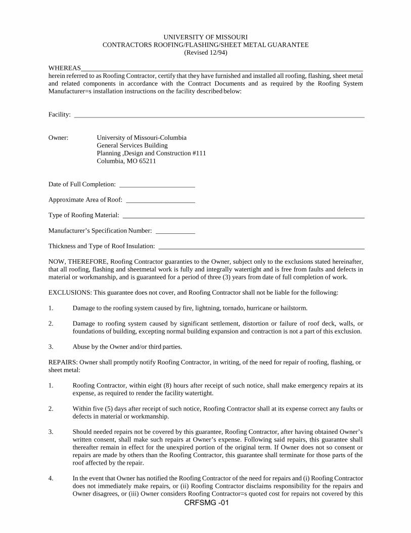
CRFSMG -01
UNIVERSITY OF MISSOURI CONTRACTORS ROOFING/FLASHING/SHEET METAL GUARANTEE
(Revised 12/94)
WHEREAS herein referred to as Roofing Contractor, certify that they have furnished and installed all roofing, flashing, sheet metal and related components in accordance with the Contract Documents and as required by the Roofing System Manufacturer=s installation instructions on the facility described below:
Facility:
Owner: University of Missouri-Columbia General Services Building Planning ,Design and Construction #111 Columbia, MO 65211
Date of Full Completion:
Approximate Area of Roof:
Type of Roofing Material:
Manufacturer’s Specification Number:
Thickness and Type of Roof Insulation:
NOW, THEREFORE, Roofing Contractor guaranties to the Owner, subject only to the exclusions stated hereinafter, that all roofing, flashing and sheetmetal work is fully and integrally watertight and is free from faults and defects in material or workmanship, and is guaranteed for a period of three (3) years from date of full completion of work.
EXCLUSIONS: This guarantee does not cover, and Roofing Contractor shall not be liable for the following:
1. Damage to the roofing system caused by fire, lightning, tornado, hurricane or hailstorm.
2. Damage to roofing system caused by significant settlement, distortion or failure of roof deck, walls, or
foundations of building, excepting normal building expansion and contraction is not a part of this exclusion.
3. Abuse by the Owner and/or third parties.
REPAIRS: Owner shall promptly notify Roofing Contractor, in writing, of the need for repair of roofing, flashing, or sheet metal:
1. Roofing Contractor, within eight (8) hours after receipt of such notice, shall make emergency repairs at its
expense, as required to render the facility watertight.
2. Within five (5) days after receipt of such notice, Roofing Contractor shall at its expense correct any faults or defects in material or workmanship.
3. Should needed repairs not be covered by this guarantee, Roofing Contractor, after having obtained Owner’s
written consent, shall make such repairs at Owner’s expense. Following said repairs, this guarantee shall thereafter remain in effect for the unexpired portion of the original term. If Owner does not so consent or repairs are made by others than the Roofing Contractor, this guarantee shall terminate for those parts of the roof affected by the repair.
4. In the event that Owner has notified the Roofing Contractor of the need for repairs and (i) Roofing Contractor
does not immediately make repairs, or (ii) Roofing Contractor disclaims responsibility for the repairs and Owner disagrees, or (iii) Owner considers Roofing Contractor=s quoted cost for repairs not covered by this

CRFSMG -02
guarantee to be unreasonable and, an emergency condition exists which requires prompt repair to avoid
substantial damage or loss to Owner, then, Owner may make such temporary repairs as he finds necessary and such action shall not be a breach of the provisions of this guarantee.
ANNUAL INSPECTIONS: Roofing Contractor shall inspect roof installation prior to each of the three anniversary dates from date of full completion of the work.
1. Inspection team to include Roofing Contractor, Roof Manufacturer, and Owner=s Representative.
2. Inspection of total roof system will be included in the annual inspections.
3. All defects in total roof system will be corrected by the Roofing Contractor within 30 days of inspection.
4. Roof manufacturer will certify by a written report that roof inspection has been completed, defects are
acknowledged, and will warrant any repairs.
5. All corrective work completed by Roofing Contractor shall be warranted as approved by the Roofing Manufacturer.
ROOF MODIFICATION: Should Owner require work to be done on roof of said facility including modifications, alternations, extensions or additions to roof and including installation of vents, platforms, equipment, bracings or fastenings, Owner shall notify Roofing Contractor and give Roofing Contractor an opportunity to make recommendations as to methods necessary to safeguard against damage to roofing covered by this guarantee. Failure of Owner to give Roofing Contractor such opportunity or failure to follow methods recommended by Roofing Contractor shall render this guarantee null and void to the extent such failure should result in damage to roofing covered by this guarantee.
NOTICES: Notification of Roofing Contractor by Owner, shall be fulfilled by sending notice to Roofing Contractor.
IN WITNESS WHEREOF, we set our hands this day of , 20 .
By:
Title:
For Roofing Contractor
Name:
Address:
Phone:

Project:
Project Number:
Contractor:
SHOP DRAWING AND SUBMITTAL LOG
Section
Description
Contractor
Date
Rec’d
#
Date Sent
to Cons.
Date
Ret’d
Remarks
Date
ret’d
Copies
To
Cont’r Owner File
SDSL - 1


Project:
Project Number:
Contractor:
OPERATING INSTRUCTIONS AND SERVICE MANUAL LOG
Section
Description
Catalog Data
Wiring
Diagrams
Installation
Instructions
Service &
Maintenance
Instructions
Parts List &
Availability
PerformanceC
urves
Startup &
Operating
Instructions
OMML - 1


Project:
Project Number:
Contractor:
CLOSEOUT LOG
Section
Description
Contractor/Subcontractor
Date
Rec’d
# of
Copies
CPM
Initials
Remarks
GC /3.11 As-built drawings
GC /13.5.6 Final Affidavit of Supplier Diversity Participation for each
Diverse firm
SC/20 Executed commissioning plan w/ required documentation
List special warranties and guarantees for each section
List any required maintenance stock, spare parts, etc.
List any special tools, keys, etc.
CLOSEOUT- 1


Sustainability Report
Material Description Ticket No. Date Material Type Weight Notes
Total weight of all demolition material:
Percentage of total material diverted:
SR-1


SECTION 1.F
INDEX OF DRAWINGS
Drawings referred to in and accompanying Project Manual consist of following sheets dated July 2, 2018.
3rd Floor Fit Out (CP150752) and 4th Floor Fit Out (CP150753) GENERAL G-000 COVER G-001 ADA TYP. & GENERAL SCHEDULES G-002 TYPICAL MOUNTING HEIGHTS G-003 PARTITION TYPES AND DETAILS G-004 UL ASSEMBLIES G-101 SECOND FLOOR CODE PLAN G-102 THIRD FLOOR CODE PLAN G-103 FOURTH FLOOR CODE PLAN STRUCTURAL S100 FOURTH FLOOR FRAMING PLAN ARCHITECTURAL AS-100 CONSTRUCTION SITE PLAN AC-101 SECOND FLOOR TEMPORARY BARRIER CONSTRUCTION PLAN AC-102 THIRD FLOOR TEMPORARY BARRIER CONSTRUCTION PLAN AC-103 FOURTH FLOOR TEMPORARY BARRIER CONSTRUCTION PLAN AD-101 THIRD FLOOR DEMOLITION PLANS AD-102 FOURTH FLOOR DEMOLITION PLAN A-101 THIRD FLOOR PLAN A-102 FOURTH FLOOR PLAN A-151 THIRD FLOOR REFLECTED CEILING PLAN A-152 FOURTH FLOOR REFLECTED CEILING PLAN A-201 BUILDING ELEVATIONS A-202 BUILDING ELEVATIONS A-411 THIRD FLOOR ENLARGED PLAN A-412 FOURTH FLOOR ENLARGED PLAN A-413 FOURTH FLOOR ENLARGED PLANS A-414 THIRD FLOOR ENLARGED REFLECTED CEILING PLAN A-415 FOURTH FLOOR ENLARGED REFLECTED CEILING PLAN A-416 FOURTH FLOOR ENLARGED REFLECTED CEILING PLANS A-501 BUILDING DETAILS A-502 BUILDING DETAILS A-503 CASEWORK DETAILS A-601 DOORS & WINDOWS A-701 INTERIOR FINISH SCHEDULE AND DETAILS A-702 INTERIOR DETAILS A-710 THIRD FLOOR FINISH PLAN A-711 FOURTH FLOOR FINISH PLAN A-721 INTERIOR ELEVATIONS - THIRD FLOOR A-722 INTERIOR ELEVATIONS - THIRD FLOOR

A-723 INTERIOR ELEVATIONS - THIRD FLOOR A-724 INTERIOR ELEVATIONS - FOURTH FLOOR A-725 INTERIOR ELEVATIONS - FOURTH FLOOR A-731 OR TYPICAL SECTIONS A-741 CASEWORK ELEVATIONS A-742 CASEWORK DETAILS FIRE PROTECTION FP103 THIRD FLOOR PLAN FIRE PROTECTION FP104 FOURTH FLOOR PLAN FIRE PROTECTION FPT103 THIRD FLOOR PLAN TEMPORARY FIRE PROTECTION FPT104 FOURTH FLOOR TEMPORARY FIRE PROTECTION PLAN FIRE ALARM FA101 THIRD FLOOR PARTIAL PLAN - FIRE ALARM FA102 FOURTH FLOOR PARTIAL PLAN - FIRE ALARM PLUMBING PD103 THIRD FLOOR DEMOLITION PLAN PLUMBING PD104 FOURTH FLOOR DEMOLITION PLAN PLUMBING P102 SECOND FLOOR PLAN PLUMBING P103 THIRD FLOOR PLAN PLUMBING P104 FOURTH FLOOR PLAN PLUMBING P401 PLUMBING WASTE AND VENT RISER DIAGRAMS P402 PLUMBING WASTE AND VENT RISER DIAGRAMS MECHANICAL M001 MECHANICAL SYMBOLS AND ABBREVIATIONS MD103 THIRD FLOOR DEMOLITION PLAN DUCTWORK MD104 FOURTH FLOOR DEMOLITION PLAN DUCTWORK MD203 THIRD FLOOR DEMOLITION PLAN MECHANICAL PIPING MD204 FOURTH FLOOR DEMOLITION PLAN MECHANICAL PIPING M102 SECOND FLOOR PLAN DUCTWORK - DEMO/NEW WORK M103 THIRD FLOOR PLAN DUCTWORK M104 FOURTH FLOOR PLAN DUCTWORK M203 THIRD FLOOR PLAN MECHANICAL PIPING M204 FOURTH FLOOR PLAN MECHANICAL PIPING M303 ENLARGED PARTIAL THIRD FLOOR PLAN DUCTWORK M304 ENLARGED PARTIAL THIRD FLOOR PLAN DUCTWORK M501 MECHANICAL DETAILS M502 MECHANICAL DETAILS M601 THIRD FLOOR AIR FLOW DIAGRAM AHU-3 M602 THIRD FLOOR AIR FLOW DIAGRAM AHU-4 M603 FOURTH FLOOR AIR FLOW DIAGRAM AHU-5 M604 FOURTH FLOOR AIR FLOW DIAGRAM AHU-6 M605 HEATING HOT WATER DIAGRAMS M701 PRESSURE CONTROL SCHEMATICS M702 TEMPERATURE CONTROL SCHEMATIC M801 MECHANICAL SCHEDULES MEDICAL GAS MG001 MECIAL GAS SYMBOLS, ABBREVIATIONS, SCHEDULES MG203 THIRD FLOOR PLAN MEDICAL GAS
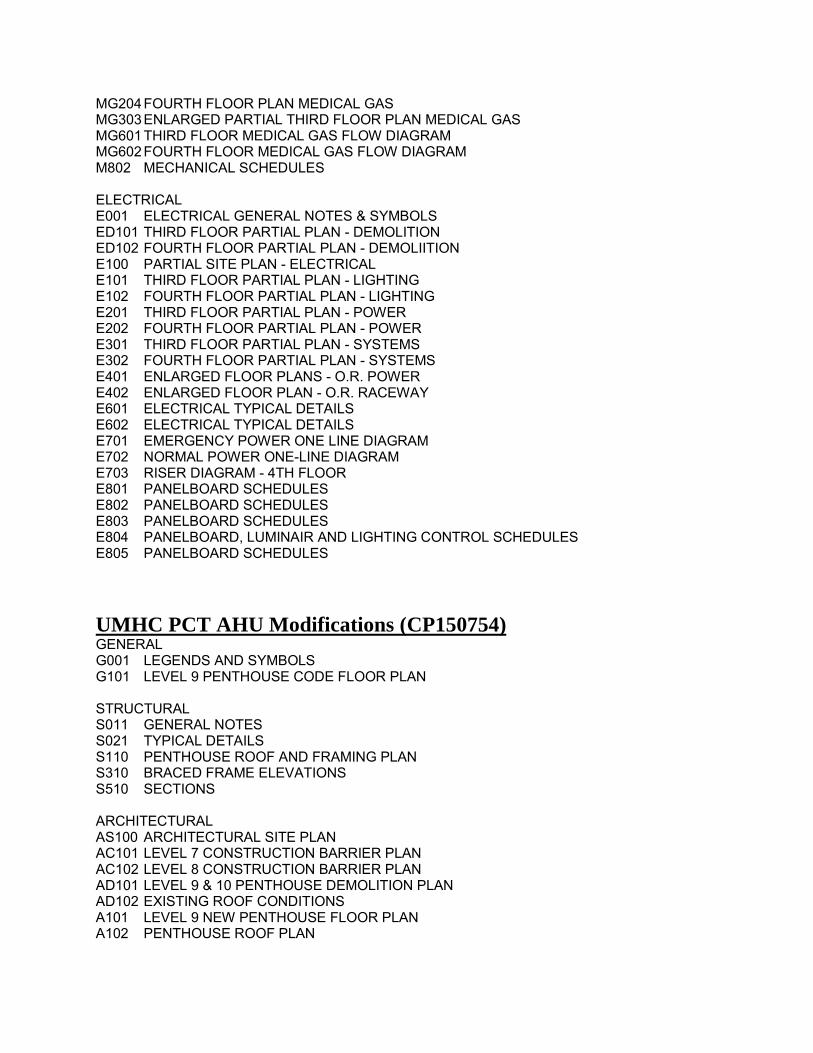
MG204 FOURTH FLOOR PLAN MEDICAL GAS MG303 ENLARGED PARTIAL THIRD FLOOR PLAN MEDICAL GAS MG601 THIRD FLOOR MEDICAL GAS FLOW DIAGRAM MG602 FOURTH FLOOR MEDICAL GAS FLOW DIAGRAM M802 MECHANICAL SCHEDULES ELECTRICAL E001 ELECTRICAL GENERAL NOTES & SYMBOLS ED101 THIRD FLOOR PARTIAL PLAN - DEMOLITION ED102 FOURTH FLOOR PARTIAL PLAN - DEMOLIITION E100 PARTIAL SITE PLAN - ELECTRICAL E101 THIRD FLOOR PARTIAL PLAN - LIGHTING E102 FOURTH FLOOR PARTIAL PLAN - LIGHTING E201 THIRD FLOOR PARTIAL PLAN - POWER E202 FOURTH FLOOR PARTIAL PLAN - POWER E301 THIRD FLOOR PARTIAL PLAN - SYSTEMS E302 FOURTH FLOOR PARTIAL PLAN - SYSTEMS E401 ENLARGED FLOOR PLANS - O.R. POWER E402 ENLARGED FLOOR PLAN - O.R. RACEWAY E601 ELECTRICAL TYPICAL DETAILS E602 ELECTRICAL TYPICAL DETAILS E701 EMERGENCY POWER ONE LINE DIAGRAM E702 NORMAL POWER ONE-LINE DIAGRAM E703 RISER DIAGRAM - 4TH FLOOR E801 PANELBOARD SCHEDULES E802 PANELBOARD SCHEDULES E803 PANELBOARD SCHEDULES E804 PANELBOARD, LUMINAIR AND LIGHTING CONTROL SCHEDULES E805 PANELBOARD SCHEDULES
UMHC PCT AHU Modifications (CP150754) GENERAL G001 LEGENDS AND SYMBOLS G101 LEVEL 9 PENTHOUSE CODE FLOOR PLAN STRUCTURAL S011 GENERAL NOTES S021 TYPICAL DETAILS S110 PENTHOUSE ROOF AND FRAMING PLAN S310 BRACED FRAME ELEVATIONS S510 SECTIONS ARCHITECTURAL AS100 ARCHITECTURAL SITE PLAN AC101 LEVEL 7 CONSTRUCTION BARRIER PLAN AC102 LEVEL 8 CONSTRUCTION BARRIER PLAN AD101 LEVEL 9 & 10 PENTHOUSE DEMOLITION PLAN AD102 EXISTING ROOF CONDITIONS A101 LEVEL 9 NEW PENTHOUSE FLOOR PLAN A102 PENTHOUSE ROOF PLAN

A201 EXTERIOR ELEVATIONS A202 EXTERIOR ELEVATIONS A301 BUILDING SECTIONS A311 WALL SECTIONS A501 NEW PENTHOUSE DETAILS A502 NEW PENTHOUSE DETAILS A503 PENTHOUSE DUCT ENCLOSURE DETAILS A504 PENTHOUSE DUCT ENCLOSURE DETAILS A505 DOOR SCHEDULE & DETAILS A901 3D VIEWS FIRE PROTECTION FP109 PENTHOUSE PLAN – FIRE PROTECTION PLUMBING - PENTHOUSE P107B SEVENTH FL PLAN AREA B – PLUBMING – NEW WORK P108B EIGHTH FLOOR PLAN AREA B – PLUMBING – NEW WORK P109B PENTHOUSE PLAN AREA B – PLUMBING – NEW WORK MECHANICAL M001 MECHANICAL SYMBOLS AND ABBREVIATIONS MD109A PENTHOUSE PLAN AREA A – MECHANICAL – DEMO MD109B PENTHOUSE PLAN AREA B – MECHANICAL – DEMO MD109R PENTHOUSE ROOF PLAN – MECHANICAL – DEMO M109A PENTHOUSE PLAN AREA A – MECHANICAL – NEW WORK M109B PENTHOUSE PLAN AREA B – MECHANICAL – NEW WORK M109R PENTHOUSE ROOF PLAN – MECHANICAL – NEW WORK M401 MECHANICAL SECTIONS M402 MECHANICAL SECTIONS M403 MECHANICAL SECTIONS M501 MECHANICAL DETAILS M601 MAU-9 & AHU-4 CONTROLS AND POINTS LIST M602 AHU-3 & AHU-4 CONTROLS AND SEQUENCE M603 CHILLED WATER FLOW DIAGRAM M604 HEATED WATER FLOW DIAGRAM M801 MECHANICAL SCHEDULES ELECTRICAL E001 ELECTRICAL SYMBOLS AND ABBREVIATIONS ED109B PENTHOUSE PLAN AREA B – ELECTRICAL DEMOLITION ED109C PENTHOUSE PLAN AREA C – ELECTRICAL DEMOLITION E109 PENTHOUSE PLAN – OVERALL ELECTRICAL NEW WORK E109A PENTHOUSE PLAN AREA A – ELECTRICAL NEW WORK E109B PENTHOUSE PLAN AREA B – ELECTRICAL NEW WORK E109R PENTHOUSE PLAN ROOF – ELECTRICAL E501 ELECTRICAL DETAILS AND CONNECTION DIAGRAMS E701 NORMAL POWER ONE-LINE DIAGRAM E702 NORMAL POWER RISER DIAGRAM E703 EMERGENCY POWER ONE-LINE DIAGRAM E704 EMERGENCY POWER RISER DIAGRAM E800 FIRE ALARM RISER AND DETAILS
END OF SECTION


CP150752,53,54 UMHC PCT 3rd and 4th FLOOR and AHU Quality Assurance Log
Commissioning Items by CSI DivisionDocumentation
RequiredOwner Witness
Required
Verified by:
Name FirmDate compl
Coord Initial
51200Structural Steel FramingProvide welder qualification report for each welder on site
Welder Qualifications
Schedule Pre-Installation Conference To Review All Details, Workmanship, and Quality Expectations
Meeting Minutes
53100Steel DeckingProvide welder qualification report for each welder on site
Welder Qualifications
54000Cold-Formed Metal FramingProvide welder qualification report for each welder on site
Welder Qualifications
200000Basic Mechanical ConditionsProvide pressure vessel permits - if applicable Pressure Vessel Permit
201000Basic Mechanical ConditionsAlign Equipment As specified Alignment Report
Firestop all thru penetrations as specified Certification
COM 1 of 106/18/2018

Commissioning Items by CSI DivisionDocumentation
RequiredOwner Witness
Required
Verified by:
Name FirmDate compl
Coord Initial
Flush pipe as specified Flush Report
Hold MEP pre-installation meeting(s). Meeting Minutes
201080Testing, Adjusting, and BalancingBalance all systems and keep a list of issues uncovered. Keep owner informed of all issues.
Issues List
Confirm approved shop drawings, as-builts, O&Ms and change orders have been submitted to the TAB engineer prior to testing and balancing
Coordinate and cooperate with owner's commissioning efforts
Coordinate temperature control testing and adjusting with temperature controls contractor
Mark equipment settings including central positions, value indicators, fan speed control levers, etc.
Notify Owner's Representative 14 days prior to the scheduled date for balancing the system.
written notification
Place outlet dampers in full open position
Provide a complete set of as-builts prior to testing
Provide final balance report to owner and consulting engineers for their review and record
Balance Report
COM 2 of 106/18/2018

Commissioning Items by CSI DivisionDocumentation
RequiredOwner Witness
Required
Verified by:
Name FirmDate compl
Coord Initial
201090Basic Mechanical Methods - IdentificationInstall pipe markers per specifications
202013MotorsCheck each motor for alignment, lubrication, rotation, voltage and current and efficiency
Inspection Report
202500InsulationVerify all piping unions are accessible for maintenance
Verify fire rating at fire dampers,walls, floors, ceilings and roof
Verify proper insulation used for piping and duct work
210000Fire Protection systemFlush, test and inspect stand piping per specifications and NFPA standards
test results report
210030Wet Pipe Sprinkler SystemTest tie-ins to fire alarm system and perform 200 psi hydrostatic testing per NFPA 13.
NFPA Documentation
231000Hydronic PipingDrain, flush and refill system with clean water. Clean and set automatic fill valves for required system pressure
COM 3 of 106/18/2018

Commissioning Items by CSI DivisionDocumentation
RequiredOwner Witness
Required
Verified by:
Name FirmDate compl
Coord Initial
hydrostatically pressure test chilled water pipe to 160 psi for 4 hours and hot water pipe to 100 psi for 4 hours. Test for 24 hours if using air.
Test Report
Remove and clean all strainers after flushing system Flush Report
232100PumpsFlush system and replace strainers
Startup with a factory trained representative and Align as required
Startup Report
232113Hydronic PipingEnsure pete's plugs, thermometers and pressure gage's are installed as specified.
232309Medical Gas and Vacuum TestingContractor to test at 150 psi with nitrogen for 24 hours
Test Reports
Test as required by this section Test Reports
237300Air Handling UnitsProvide factory training Sign in sheet
Provide startup with a factory trained technician Startup Report
COM 4 of 106/18/2018

Commissioning Items by CSI DivisionDocumentation
RequiredOwner Witness
Required
Verified by:
Name FirmDate compl
Coord Initial
243100Sheetmetal Ductworktest for duct leakage per "Ductwork Leakage Testing" section of spec.and below. Ducts shall meet leakage requirement prior to testing and balancing. Meet Leakage class of 4
test report
243300Air Duct AccessoriesDemonstrate Proper Operation of All Fire Dampers per NFPA-90A.
test report
243400FansEnergize motor; Check drive system and fan wheel; Adjust fan to required rpm.
250000Temperature Control SystemsFirestop as required by specifications Certification
Install and assist at start up as specified
Start, test and adjust controls and safeties
Test and adjust temperature controls in coordination with TAB engineer
Verify all field devices provided by contractor are terminated
Verify all panel covers are installed
COM 5 of 106/18/2018

Commissioning Items by CSI DivisionDocumentation
RequiredOwner Witness
Required
Verified by:
Name FirmDate compl
Coord Initial
Verify control wiring and/or pneumatic tubing from all devices to Metasys panel
Verify method of labeling used for identification has been defined to the Owners Representative
Verify power to all EMCS panels and equipment is complete
Verify safety alarms hard wired to control panels
Verify systems are completely operable and ready for testing and balancing
260500Common Work Results for ElectricalVerify that every penetration through fire walls (re: life safety plans) has been properly firestopped
certification
260519Low-Voltage Electrical Power Conductors and CablesPerform independent tests per "Field Quality Control" section of spec, including megohm/high pot tests
test report
260526Grounding and Bonding for Electrical SystemsConduct grounding tests per Field Quality Control Section of specifications
test reports
260536Cable Trays for Electrical SystemsPerform resistance test as described in "Field Quality Control" section of spec
Test Reports
COM 6 of 106/18/2018

Commissioning Items by CSI DivisionDocumentation
RequiredOwner Witness
Required
Verified by:
Name FirmDate compl
Coord Initial
260543Vibration and Seismic Controls for Electrical SystemsPerform tests as noted in "Field Quality Control" section of spec
Test Report
260553Identification for Electrical SystemsEnsure identification devices are applied per specifications
260573Overcurrent Protective Device Coordination StudyFactory certified technician to set electronic overcurrent devices to approved coordination study setpoints
Inspection Report
Train owners representatives in setting of overcurrent devices
Sign-up Sheet
260923Lighting Control DevicesPerform Commissioning as noted in "Factory Commissioning" section of spec
Commissioning Report
Perform tests as noted in "Field Quality Control" section of spec
field report
Provide factory training per demonstration section of specifications
Sign-in sheet
262200Low-Voltage TransformersPerform checks and tests as noted in "Field Quality Control Testing" section of spec
test report
COM 7 of 106/18/2018

Commissioning Items by CSI DivisionDocumentation
RequiredOwner Witness
Required
Verified by:
Name FirmDate compl
Coord Initial
262416PanelboardsPerform checks per "Field Quality Control" and "Testing" section of spec. Including torque checks.
Test Report
262726Wiring DevicesCheck all switches for proper operation per field quality control section of specifications
document on field copy of drawings
262813FusesFurnish extra material as specified Transmittal
Test for continuity and short circuits prior to energization
262816Enclosed Switches and Circuit BreakersPerform tests per "Field Quality Control" section of spec
Test Report
Provide Extra Material as specified Transmittal
262923Variable-Frequency Motor ControllersProvide factory trained start-up and testing per Field Quality Control section of specifications
start-up & test log; service rep report
Provide factory training per demonstration section of specifications
Sign-in Sheet
COM 8 of 106/18/2018

Commissioning Items by CSI DivisionDocumentation
RequiredOwner Witness
Required
Verified by:
Name FirmDate compl
Coord Initial
264113Lightning Protection for StructuresProvide periodic and final inspections as required by LPI-177 in order to obtain UL Master Label
field report, certification, and Master Label
265000LightingTest all fixtures for proper operation per field quality control section of specifications. Perform startup service section of specifications
Test reports
265100Interior LightingBuild mockups as specified Inspection report
Provide extra material as specified Transmittal
Test Emergency Lighting fixtures for proper operation
Test Report
270500Common Work Results for CommunicationsInstall firestopping as specified Certification
283111Digital, Addressable Fire-Alarm SystemPretest system prior to testing with owners representative
Pretest checklist
Provide factory training per demonstration section of specifications
Sign-in Sheet
COM 9 of 106/18/2018

Commissioning Items by CSI DivisionDocumentation
RequiredOwner Witness
Required
Verified by:
Name FirmDate compl
Coord Initial
Test system per field quality control section of specifications
Written certification of fire alrm system per NFPA
Verify battery power available
COM 10 of 106/18/2018

Please see following website for suggested commissioning forms:
http://www.cf.missouri.edu/pdc/commissioning‐forms.html


Missouri
Division of Labor StandardsWAGE AND HOUR SECTION
ERIC R. GREITENS, Governor
Annual Wage Order No. 25Section 010
BOONE COUNTY
In accordance with Section 290.262 RSMo 2000, within thirty (30) days after a certified copy of thisAnnual Wage Order has been filed with the Secretary of State as indicated below, any person who maybe affected by this Annual Wage Order may object by filing an objection in triplicate with the Labor andIndustrial Relations Commission, P.O. Box 599, Jefferson City, MO 65102-0599. Such objections mustset forth in writing the specific grounds of objection. Each objection shall certify that a copy has beenfurnished to the Division of Labor Standards, P.O. Box 449, Jefferson City, MO 65102-0449 pursuant to8 CSR 20-5.010(1). A certified copy of the Annual Wage Order has been filed with the Secretary ofState of Missouri.
Original Signed by
Matt Cowell, Director
Division of Labor Standards
Filed With Secretary of State: March 9.2018
Last Date Objections May Be Filed: April 9.2018
Prepared by Missouri Department of Labor and Industrial Relations

Building Construction Rates forBOONE County
REPLACEMENT PAGE Section 010
OCCUPATIONAL TITLE ** Date of
Increase
*
Basic
HourlyRates
Over-
Time
Schedule
HolidaySchedule
Total Fringe Benefits
Asbestos Worker (H & F) Insulator $32.70 55 60 $23.17Boilermaker 6/18 $37.91 57 7 $29.38Bricklayer and Stone Mason 6/18 $30.00 59 7 $18.19Carpenter 6/18 $26.15 60 15 $17.10Cement Mason 6/18 $28.53 9 3 $12.92Communication Technician 6/18 $32.50 28 7 $13.50 + 13%Electrician (Inside Wireman) 6/18 $32.50 28 7 $13.50 + 13%Electrician (Outside-Line Construction\Lineman) $44.56 43 45 $5.75 + 36%Lineman Operator $38.35 43 45 $5.75 + 36%Groundman $29.48 43 45 $5.75 + 36%
Elevator Constructor a $47.07 26 54 $33,275Glazier 6/18 $27.56 122 76 $12.74Ironworker $29.49 11 8 $25.96Laborer (Building):General $23.71 42 44 $13.84
First Semi-Skilled $25.71 42 44 $13.84Second Semi-Skilled $24.71 42 44 $13.84
Lather USE CARPENTER RATE
Linoleum Layer and Cutter 6/18 $26.03 60 15 $17.10Marble Mason $22.24 124 74 $13.05Marble Finisher $14.35 124 74 $9.52Millwright 6/18 $27.17 60 15 $17.10
Operating EngineerGroup 1 6/18 $29.16 86 66 $27.17Group II 6/18 $29.16 86 66 $27.17Group III 6/18 $27.91 86 66 $27.17Group lll-A 6/18 $29.16 86 66 $27.17Group IV 6/18 $26.93 86 66 $27.17Group V 6/18 $29.86 86 66 $27.17
Painter 6/18 $23.93 18 7 $12.74Pile Driver 6/18 $27.17 60 15 $17.10Pipe Fitter b $39.25 91 69 $27.18
Plasterer 6/18 $27.02 94 5 $12.97Plumber b $39.25 91 69 $27.18Roofer \ Waterproofer $29.55 12 4 $16.04Sheet Metal Worker $31.55 40 23 $17.88Sprinkler Fitter - Fire Protection 6/18 $35.84 33 19 $21.42Terrazzo Worker $29.55 124 74 $14.76
Terrazzo Finisher $19.22 124 74 $14.76
Tile Setter $22.24 124 74 $13.05Tile Finisher $14.35 124 74 $9.52Traffic Control Service Driver $26,415 22 55 $9,045Truck Driver-Teamster
Group 1 $25.30 101 5 $10.70Group II $25.95 101 5 $10.70Group III $25.45 101 5 $10.70Group IV $25.95 101 5 $10.70
Fringe Benefit Percentage is of the Basic Hourly Rate
'Annual Incremental Increase
•SEE FOOTNOTE PAGE ANNUAL WAGE ORDER NO. 25 6/18


ALLOWANCES 012100 - Page 1
TreanorHL UM Projects # CP150752, CP150753 & CP150754
UMHC PCT 3rd and 4th Floor Fit Out UMHC PCT AHU Modification
SECTION 012100 – ALLOWANCES
PART 1 – GENERAL
1.1 SUMMARY
A. Section includes administrative and procedural requirements governing allowances.
B. Types of allowances include the following:
1. Lump-sum allowances.
1.2 DEFINITIONS
A. Allowance is a quantity of work or dollar amount established in lieu of additional requirements, used to defer selection of actual materials and equipment to a later date when direction will be provided to Contractor. If necessary, additional requirements will be issued by Change Order.
1.3 SELECTION AND PURCHASE
A. At the earliest practical date after award of the Contract, advise Architect of the date when final selection, or purchase and delivery, of each product or system described by an allowance must be completed by the Owner to avoid delaying the Work.
B. At Architect's request, obtain proposals for each allowance for use in making final selections. Include recommendations that are relevant to performing the Work.
C. Purchase products and systems selected by Architect from the designated supplier.
1.4 ACTION SUBMITTALS
A. Submit proposals for purchase of products or systems included in allowances in the form specified for Change Orders.
1.5 INFORMATIONAL SUBMITTALS
A. Submit invoices or delivery slips to show actual quantities of materials delivered to the site for use in fulfillment of each allowance.

ALLOWANCES 012100 - Page 2
TreanorHL UM Projects # CP150752, CP150753 & CP150754
UMHC PCT 3rd and 4th Floor Fit Out UMHC PCT AHU Modification
B. Submit time sheets and other documentation to show labor time and cost for installation of allowance items that include installation as part of the allowance.
1.6 LUMP-SUM ALLOWANCES
A. Allowance shall include cost to Contractor of specific products and materials ordered by Owner or selected by Architect under allowance and shall include and delivery to Project site.
B. Unless otherwise indicated, Contractor's costs for receiving and handling at Project site, labor, installation, overhead and profit, and similar costs related to products and materials ordered by Owner or selected by Architect under allowance shall be included as part of the Contract Sum and not part of the allowance.
1.7 ADJUSTMENT OF ALLOWANCES
A. Allowance Adjustment: Unused monies from any/all allowances shall be returned to the Owner by way of a formal change order at the conclusion of the project. Any such credit change order shall include applicable mark-ups consistent with Article 7 of the General Conditions in addition to the returned allowance amount.
B. Each Allowance will be a separate line item in the Schedule of Values. All work completed using the allowance requires the prior written approval of the Owner’s representative and will be completed on a time and material basis utilizing the applicable labor rates approved by the Owner.
PART 2 – PRODUCTS (Not Used)
PART 3 - EXECUTION
3.1 EXAMINATION
A. Examine products covered by an allowance promptly on delivery for damage or defects. Return damaged or defective products to manufacturer for replacement.
3.2 PREPARATION
A. Coordinate materials and their installation for each allowance with related materials and installations to ensure that each allowance item is completely integrated and interfaced with related work.

ALLOWANCES 012100 - Page 3
TreanorHL UM Projects # CP150752, CP150753 & CP150754
UMHC PCT 3rd and 4th Floor Fit Out UMHC PCT AHU Modification
3.3 SCHEDULE OF ALLOWANCES
A. Allowance No. 1: Lump-Sum Allowance: Bidder shall include in the base bid sum an allowance of $30,000.00 (Thirty Thousand Dollars and no cents) above and beyond the work included in the Base Bid for Infection Control barriers not specifically shown on the plans to be used at the Owner’s discretion during the course of the project. This allowance shall not include Infection Control Measures shown in the Bid Documents. This allowance amount shall include overhead and profit on the allowance amount in his bid. This allowance shall be utilized at the Owners discretion.
B. Allowance No. 2: Lump-Sum Allowance: Bidder shall include in the base bid sum an allowance of $10,000.00 (Ten Thousand Dollars and no cents) for Existing Condition Missing or Non-Compliant Firestopping / Through Wall Penetration Firestop assemblies uncovered during construction. This allowance amount shall include contractor's labor, material, overhead and profit on the allowance amount in his bid. This allowance shall be utilized at the Owners discretion. END OF SECTION 012100

THIS PAGE INTENTIONALLY LEFT BLANK

INDOOR AIR QUALITY /EQUIPMENT 013329 -Page 1
TreanorHL UM Projects # CP150752, CP150753 & CP150754
UMHC PCT 3rd and 4th Floor Fit Out UMHC PCT AHU Modification
SECTION 01 33 29 – INDOOR AIR QUALITY / EQUIPMENT
PART 1 - GENERAL
1.1 SECTION INCLUDES
A. Construction procedures to promote adequate indoor air quality after construction, by managing the indoor air quality during the construction and preoccupancy phases of the project.
B. Mobile Containment Cube
1.2 PROJECT GOALS A. Dust and Airborne Particulates: Prevent deposition of dust and other
particulates in HVAC ducts and equipment.
1. Cleaning of ductwork is not contemplated under this Contract. 2. Contractor shall bear the cost of cleaning required due to failure to
protect ducts and equipment from construction dust. 3. Establish condition of existing ducts and equipment prior to start of
alterations.
B. Airborne Contaminants: Procedures and products have been specified to minimize indoor air pollutants.
1. Furnish products meeting the specifications. 2. Avoid construction practices that could result in contamination of
installed products leading to indoor air pollution.
1.3 REFERENCE STANDARDS A. ASHRAE Std 52.2 - Method of Testing General Ventilation Air-Cleaning
Devices for Removal Efficiency by Particle Size; 2007.
B. SMACNA (OCC) - IAQ Guideline for Occupied Buildings Under Construction; 2007.
C. Federal Std. 191A, Test Method 5903, MVSS 320, CA Fire Marshal
(containment cube)
D. Meets Relevant CDC, CSA Z317.13-03, AIA, ASHE & NFPA 101 Life Safety Code Requirements. (containment cube)
1.4 DEFINITIONS
A. Adsorptive Materials: Gypsum board, acoustical ceiling tile and panels, carpet and carpet tile, fabrics, fibrous insulation, and other similar products.
B. Contaminants: Gases, vapors, regulated pollutants, airborne mold and
mildew, and the like, as specified.
C. Particulates: Dust, dirt, and other airborne solid matter.

INDOOR AIR QUALITY /EQUIPMENT 013329 -Page 2
TreanorHL UM Projects # CP150752, CP150753 & CP150754
UMHC PCT 3rd and 4th Floor Fit Out UMHC PCT AHU Modification
D. Wet Work: Concrete, plaster, coatings, and other products that emit water vapor or volatile organic compounds during installation, drying, or curing.
1.5 SUBMITTALS
A. See General Conditions Article 6.10 - Shop Drawings, Product Data & Samples.
1. Signed statement describing the building air flush-out procedures including the dates when flush-out was begun and completed and statement that filtration media was replaced after flush-out.
2. Product data for filtration media used during flush-out and during occupancy. Use IAQ form in Division 1 Section 1.E.3.
3. Report from testing and inspection agency indicating results of indoor-air-quality testing and documentation showing compliance with indoor-air-quality procedures and requirements.
B. Indoor Air Quality Management Plan: Describe in detail measures to be
taken to promote adequate indoor air quality upon completion; use SMACNA IAQ Guidelines for Occupied Buildings Under Construction as a guide.
1. Submit not less than 60 days before enclosure of building. 2. Identify potential sources of odor and dust. 3. Identify construction activities likely to produce odor or dust. 4. Identify areas of project potentially affected, especially occupied areas. 5. Evaluate potential problems by severity and describe methods of control. 6. Describe construction ventilation to be provided, including type and
duration of ventilation, use of permanent HVAC systems, types of filters and schedule for replacement of filters.
7. Describe cleaning and dust control procedures.
C. Product Data (containment cube): For each type of product listed. Include rated capacities, operating characteristics and furnished specialties.
D. Operation and Maintenance Manual Data (containment cube) E. Product Data for negative air fan and HEPA filters (containment cube)
PART 2 - PRODUCTS A.1 MATERIALS
A. Low VOC Materials: See other sections for specific requirements for materials with low VOC content.
B. Auxiliary Air Filters: MERV of 10, minimum, when tested in accordance with ASHRAE 52.2.
A.2 EQUIPMENT
A. Mobile Containment Cube shall be a: A.1 HEPACART Series HC55U/HC74U
A. HEPACART, 9825 Widmer Road, Lenexa, KS 66215, 913.789.9590 Scott Keeler [email protected]
A.2 approved equal.

INDOOR AIR QUALITY /EQUIPMENT 013329 -Page 3
TreanorHL UM Projects # CP150752, CP150753 & CP150754
UMHC PCT 3rd and 4th Floor Fit Out UMHC PCT AHU Modification
B. Unit shall consist of a 4- sided cabinet base constructed of steel and aluminum that is a minimum height of 64 inches, with a two-stage flexible telescoping curtain at the top of the unit that spans the space between the top of the base unit and the ceiling.
▪ The telescoping curtain of the unit shall be made of flame-retardant material.
▪ Unit shall reach ceiling heights of up to 10 feet. The top of the telescoping curtain shall have a seal to prevent air leakage where the curtain meets the ceiling surface.
▪ Top frame shall have the ability to slide-out up to eight inches out to accommodate space around handrails and wall obstacles.
▪ Unit shall have full range, swivel-lock, non-marring casters (minimum of 4 per unit) to move and maneuver the unit.
▪ The unit shall be capable of moving through a 3-foot wide and 80 inch-high door opening when the telescoping curtain is retracted into the base unit.
C. The unit shall have an integral, built-in variable speed negative air unit with HEPA filtration, to include pre-filters and HEPA filter, to meet ISO class 5 certification standards.
▪ The unit shall be certified by the manufacturer. ▪ The negative air unit shall be capable of variable speeds
providing a minimum 300 cubic feet per minute (cfm) capacity and a maximum of 500 cfm.
▪ Filters shall havea minimum 500 hour life between replacements. Units shall be delivered with all new filters.
▪ The unit shall have an on/off switch to power the HEPA filtration on both the inside and outside of the unit.
▪ The interior space of the unit shall be large enough for one person; the interior space of the unit shall safely allow the use of a 6-foot high (minimum) step ladder.
D. Provide Total Vinyl/ Cloth Dust Cover • to reduce dust accumulation and protect sidewalls and filtration exhaust area while unit is in storage or during transport.
PART 3 - EXECUTION 3.1 PROJECT CONSTRAINTS / CONTAINMENT CUBE PURCHASE FOR PROJECT
A. Contractor shall purchase a minimum of one (1) containment cube to be used for the duration of the project by Contractors forces.
B. Upon completion of the project the unit shall be thoroughly cleaned and repaired as required to ensure all functions of he mobile cube operate as intended. Turn over to the Hospital via coordinated effort with the Owners Representative.
3.2 CONSTRUCTION PROCEDURES
A. Prevent the absorption of moisture and humidity by adsorptive materials by:
1. Sequencing the delivery of such materials so that they are not

INDOOR AIR QUALITY /EQUIPMENT 013329 -Page 4
TreanorHL UM Projects # CP150752, CP150753 & CP150754
UMHC PCT 3rd and 4th Floor Fit Out UMHC PCT AHU Modification
present in the building until wet work is completed and dry. 2. Delivery and storage of such materials in fully sealed moisture-
impermeable packaging. 3. Provide sufficient ventilation for drying within reasonable time frame.
B. Begin construction ventilation prior to starting any construction.
C. Block off all existing HVAC systems serving renovation areas for the duration
of the project; remove dust and dirt completely before re-connecting to and opening HVAC systems to renovated area.
D. When working in a portion of an occupied building, prevent movement of air
from construction area to occupied area.
E. Existing HVAC equipment and ductwork may NOT be used for heating and cooling during construction:
1. Provide temporary ventilation equivalent to 1.5 air changes per hour,
minimum. 2. Exhaust directly to outside. 3. Seal HVAC air inlets and outlets immediately after duct installation. 4. Refer to Division 1 for additional information on temporary heating
and cooling requirements.
F. Do not store construction materials or waste in mechanical or electrical rooms.
G. Prior to use of return air ductwork without intake filters clean up and remove dust and debris generated by construction activities.
1. Inspect duct intakes, return air grilles, and terminal units for dust. 2. Clean plenum spaces, including top sides of lay-in ceilings,
outsides of ducts, tops of pipes and conduit. 3. Clean tops of doors and frames. 4. Clean mechanical and electrical rooms, including tops of pipes,
ducts, and conduit, equipment, and supports. 5. Clean return plenums of air handling units. 6. Remove intake filters last, after cleaning is complete.
H. Do not perform dusty or dirty work after starting use of return air ducts
without intake filters.
I. Use other relevant recommendations of SMACNA IAQ Guideline for Occupied Buildings Under Construction for avoiding unnecessary contamination due to construction procedures.
END OF SECTION 01 33 29

QUALITY REQUIREMENTS 014000 – Page 1
TreanorHL UM Projects # CP150752, CP150753 & CP150754
UMHC PCT 3rd and 4th Floor Fit Out UMHC PCT AHU Modification
SECTION 014000 - QUALITY REQUIREMENTS
PART 1 - GENERAL
1.1 SUMMARY
A. Section includes administrative and procedural requirements for quality assurance and quality control.
B. Testing and inspecting services are required to verify compliance with requirements
specified or indicated. These services do not relieve Contractor of responsibility for compliance with the Contract Document requirements.
1. Specific quality-assurance and -control requirements for individual construction
activities are specified in the Sections that specify those activities. Requirements in those Sections may also cover production of standard products.
2. Specified tests, inspections, and related actions do not limit Contractor's other quality- assurance and -control procedures that facilitate compliance with the Contract Document requirements.
3. Requirements for Contractor to provide quality-assurance and -control services required by the Owners Representative or authorities having jurisdiction are not limited by provisions of this Section.
4. Specific test and inspection requirements are not specified in this Section.
1.2 DEFINITIONS
A. Quality-Assurance Services: Activities, actions, and procedures performed before and during execution of the Work to guard against defects and deficiencies and substantiate that proposed construction will comply with requirements.
B. Quality-Control Services: Tests, inspections, procedures, and related actions during and
after execution of the Work to evaluate that actual products incorporated into the Work and completed construction comply with requirements. Services do not include contract enforcement activities performed by Architect or Construction Manager.
C. Mockups: Full-size physical assemblies that are constructed on-site. Mockups are
constructed to verify selections made under Sample submittals; to demonstrate aesthetic effects and, where indicated, qualities of materials and execution; to review coordination, testing, or operation; to show interface between dissimilar materials; and to demonstrate compliance with specified installation tolerances. Mockups are not Samples. Unless otherwise indicated, approved mockups establish the standard by which the Work will be judged.

QUALITY REQUIREMENTS 014000 – Page 2
TreanorHL UM Projects # CP150752, CP150753 & CP150754
UMHC PCT 3rd and 4th Floor Fit Out UMHC PCT AHU Modification
1.3 CONFLICTING REQUIREMENTS
A. Referenced Standards: If compliance with two or more standards is specified and the
standards establish different or conflicting requirements for minimum quantities or quality levels, comply with the most stringent requirement. Refer conflicting requirements that are different, but apparently equal, to Architect for a decision before proceeding.
B. Minimum Quantity or Quality Levels: The quantity or quality level shown or specified shall
be the minimum provided or performed. The actual installation may comply exactly with the minimum quantity or quality specified, or it may exceed the minimum within reasonable limits. To comply with these requirements, indicated numeric values are minimum or maximum, as appropriate, for the context of requirements. Refer uncertainties to Architect for a decision before proceeding.
1.4 INFORMATIONAL SUBMITTALS
A. Qualification Data : For Contractor's quality-control personnel.
B. Testing Agency Qualifications: For testing agencies specified in "Quality Assurance" Article to demonstrate their capabilities and experience. Include proof of qualifications in the form of a recent report on the inspection of the testing agency by a recognized authority.
C. Schedule of Tests and Inspections: Prepare in tabular form and include the following:
1. Specification Section number and title. 2. Entity responsible for performing tests and inspections. 3. Description of test and inspection. 4. Identification of applicable standards. 5. Identification of test and inspection methods. 6. Number of tests and inspections required. 7. Time schedule or time span for tests and inspections. 8. Requirements for obtaining samples. 9. Unique characteristics of each quality-control service.
1.5 REPORTS AND DOCUMENTS
A. Test and Inspection Reports: Prepare and submit certified written reports specified in other Sections. Include the following:
1. Date of issue. 2. Project title and number. 3. Name, address, and telephone number of testing agency. 4. Dates and locations of samples and tests or inspections. 5. Names of individuals making tests and inspections. 6. Description of the Work and test and inspection method. 7. Identification of product and Specification Section.

QUALITY REQUIREMENTS 014000 – Page 3
TreanorHL UM Projects # CP150752, CP150753 & CP150754
UMHC PCT 3rd and 4th Floor Fit Out UMHC PCT AHU Modification
8. Complete test or inspection data. 9. Test and inspection results and an interpretation of test results. 10. Record of temperature and weather conditions at time of sample taking and
testing and inspecting. 11. Comments or professional opinion on whether tested or inspected Work complies
with the Contract Document requirements. 12. Name and signature of laboratory inspector. 13. Recommendations on retesting and reinspecting.
B. Manufacturer's Technical Representative's Field Reports: Prepare written information
documenting manufacturer's technical representative's tests and inspections specified in other Sections. Include the following:
1. Name, address, and telephone number of technical representative making report. 2. Statement on condition of substrates and their acceptability for installation of
product. 3. Statement that products at Project site comply with requirements. 4. Summary of installation procedures being followed, whether they comply with
requirements and, if not, what corrective action was taken. 5. Results of operational and other tests and a statement of whether observed
performance complies with requirements. 6. Statement whether conditions, products, and installation will affect warranty. 7. Other required items indicated in individual Specification Sections.
1.6 QUALITY ASSURANCE
A. General: Qualifications paragraphs in this article establish the minimum qualification levels required; individual Specification Sections specify additional requirements.
B. Manufacturer Qualifications: A firm experienced in manufacturing products or systems
similar to those indicated for this Project and with a record of successful in-service performance, as well as sufficient production capacity to produce required units.
C. Fabricator Qualifications: A firm experienced in producing products similar to those
indicated for this Project and with a record of successful in-service performance, as well as sufficient production capacity to produce required units.
D. Installer Qualifications: A firm or individual experienced in installing, erecting, or
assembling work similar in material, design, and extent to that indicated for this Project, whose work has resulted in construction with a record of successful in-service performance.
E. Professional Engineer Qualifications: A professional engineer who is legally qualified to
practice in jurisdiction where Project is located and who is experienced in providing engineering services of the kind indicated. Engineering services are defined as those performed for installations of the system, assembly, or product that are similar in material, design, and extent to those indicated for this Project.
QUALITY REQUIREMENTS
014000 – Page 4
TreanorHL UM Projects # CP150752, CP150753 & CP150754
UMHC PCT 3rd and 4th Floor Fit Out UMHC PCT AHU Modification
F. Testing Agency Qualifications: An NRTL, an NVLAP, or an independent agency with
the experience and capability to conduct testing and inspecting indicated, as documented according to ASTM E 329.
1. NRTL: A nationally recognized testing laboratory according to 29 CFR 1910.7. 2. NVLAP: A testing agency accredited according to NIST's National Voluntary
Laboratory Accreditation Program.
G. Manufacturer's Technical Representative Qualifications: An authorized representative of manufacturer who is trained and approved by manufacturer to observe and inspect installation of manufacturer's products that are similar in material, design, and extent to those indicated for this Project.
H. Factory-Authorized Service Representative Qualifications: An authorized
representative of manufacturer who is trained and approved by manufacturer to inspect installation of manufacturer's products that are similar in material, design, and extent to those indicated for this Project.
1.7 QUALITY CONTROL
A. Owner Responsibilities: Where quality-control services are indicated as Owner's responsibility, Owner will engage a qualified testing agency to perform these services.
B. Contractor Responsibilities: Tests and inspections not explicitly assigned to Owner
are Contractor's responsibility. Perform additional quality-control activities required to verify that the Work complies with requirements, whether specified or not.
C. Manufacturer's Field Services: Where indicated, engage a factory-authorized service
representative to inspect field-assembled components and equipment installation, including service connections. Report results in writing.
D. Manufacturer's Technical Services: Where indicated, engage a manufacturer's
technical representative to observe and inspect the Work. Manufacturer's technical representative's services include participation in preinstallation conferences, examination of substrates and conditions, verification of materials, observation of Installer activities, inspection of completed portions of the Work, and submittal of written reports.
E. Retesting/Reinspecting: Regardless of whether original tests or inspections were
Contractor's responsibility, provide quality-control services, including retesting and reinspecting, for construction that replaced Work that failed to comply with the Contract Documents.
F. Coordination: Coordinate sequence of activities to accommodate required quality-
assurance and -control services with a minimum of delay and to avoid necessity of removing and replacing construction to accommodate testing and inspecting.

QUALITY REQUIREMENTS
014000 – Page 5
TreanorHL UM Projects # CP150752, CP150753 & CP150754
UMHC PCT 3rd and 4th Floor Fit Out UMHC PCT AHU Modification
1. Schedule times for tests, inspections, obtaining samples, and similar activities.
G. Schedule of Tests and Inspections: Prepare a schedule of tests, inspections, and similar quality- control services required by the Contract Documents. Coordinate and submit concurrently with Contractor's construction schedule. Update as the Work progresses.
PART 2 - PRODUCTS (N/A)
PART 3 - EXECUTION
3.1 TEST AND INSPECTION LOG
A. Test and Inspection Log: Prepare a record of tests and inspections. Include the following:
1. Date test or inspection was conducted. 2. Description of the Work tested or inspected. 3. Date test or inspection results were transmitted to Architect. 4. Identification of testing agency or special inspector conducting test or
inspection.
B. Maintain log at Project site. Post changes and revisions as they occur. Provide access to test and inspection log for Architect's, and Owners Representative reference during normal working hours.
3.2 REPAIR AND PROTECTION
A. General: On completion of testing, inspecting, sample taking, and similar services, repair damaged construction and restore substrates and finishes.
1. Provide materials and comply with installation requirements specified in other
Specification Sections or matching existing substrates and finishes. Restore patched areas and extend restoration into adjoining areas with durable seams that are as invisible as possible. Comply with the Contract Document requirements for cutting and patching in Section 017300 "Execution."
B. Protect construction exposed by or for quality-control service activities.
C. Repair and protection are Contractor's responsibility, regardless of the assignment of
responsibility for quality-control services.
END OF SECTION 01 40 00

THIS PAGE INTENTIONALLY LEFT BLANK

EXECUTION 017300 -Page 1
TreanorHL UM Projects # CP150752, CP150753 & CP150754
UMHC PCT 3rd and 4th Floor Fit Out UMHC PCT AHU Modification
SECTION 017300 -EXECUTION
PART 1 - GENERAL
1.1 SUMMARY
A. Section includes general administrative and procedural requirements governing execution of the Work including, but not limited to, the following: 1. Installation of the Work. 2. Coordination of Owner-installed products. 3. Progress cleaning. 4. Protection of installed construction.
B. Related Requirements:
1. Section 024119 "Selective Demolition" for demolition and removal of selected portions of the building and Cutting and Patching.
2. Section 078413 "Penetration Firestopping" for patching penetrations in fire-rated construction.
1.2 DEFINITIONS
A. Cutting: Removal of in-place construction necessary to permit installation or performance of other work.
B. Patching: Fitting and repair work required to restore construction to original
conditions after installation of other work.
PART 2 - PRODUCTS
2.1 MATERIALS
A. General: Comply with requirements specified in other Sections.
PART 3 - EXECUTION
3.1 EXAMINATION
A. Existing Conditions: The existence and location of underground and other utilities and construction indicated as existing are not guaranteed. Before beginning sitework, investigate and verify the existence and location of underground utilities, and other construction affecting the Work.
B. Examination and Acceptance of Conditions: Before proceeding with each component
of the Work, examine substrates, areas, and conditions, with Installer or Applicator present where indicated, for compliance with requirements for installation tolerances

EXECUTION 017300 -Page 2
TreanorHL UM Projects # CP150752, CP150753 & CP150754
UMHC PCT 3rd and 4th Floor Fit Out UMHC PCT AHU Modification
and other conditions affecting performance. Record observations.
1. Examine roughing-in for mechanical and electrical systems to verify actual locations of connections before equipment and fixture installation.
2. Examine walls, floors, and roofs for suitable conditions where products and systems are to be installed.
3. Verify compatibility with and suitability of substrates, including compatibility with existing finishes or primers.
C. Written Report: Where a written report listing conditions detrimental to performance
of the Work is required by other Sections, include the following:
1. Description of the Work. 2. List of detrimental conditions, including substrates. 3. List of unacceptable installation tolerances. 4. Recommended corrections.
D. Proceed with installation only after unsatisfactory conditions have been corrected.
Proceeding with the Work indicates acceptance of surfaces and conditions.
3.2 PREPARATION
A. Field Measurements: Take field measurements as required to fit the Work properly. Recheck measurements before installing each product. Where portions of the Work are indicated to fit to other construction, verify dimensions of other construction by field measurements before fabrication. Coordinate fabrication schedule with construction progress to avoid delaying the Work.
B. Space Requirements: Verify space requirements and dimensions of items shown
diagrammatically on Drawings.
C. Review of Contract Documents and Field Conditions: Immediately on discovery of the need for clarification of the Contract Documents caused by differing field conditions outside the control of Contractor, submit a request for information to Architect.
3.3 INSTALLATION
A. General: Locate the Work and components of the Work accurately, in correct
alignment and elevation, as indicated.
1. Make vertical work plumb and make horizontal work level. 2. Where space is limited, install components to maximize space available for
maintenance and ease of removal for replacement. 3. Conceal pipes, ducts, and wiring in finished areas unless otherwise indicated.
B. Comply with manufacturer's written instructions and recommendations for installing
products in applications indicated.
C. Install products at the time and under conditions that will ensure the best possible

EXECUTION 017300 -Page 3
TreanorHL UM Projects # CP150752, CP150753 & CP150754
UMHC PCT 3rd and 4th Floor Fit Out UMHC PCT AHU Modification
results. Maintain conditions required for product performance until Substantial Completion.
D. Conduct construction operations so no part of the Work is subjected to damaging
operations or loading in excess of that expected during normal conditions of occupancy.
E. Sequence the Work and allow adequate clearances to accommodate movement of
construction items on site and placement in permanent locations.
F. Tools and Equipment: Do not use tools or equipment that produce harmful noise levels.
G. Templates: Obtain and distribute to the parties involved templates for work specified
to be factory prepared and field installed. Check Shop Drawings of other work to confirm that adequate provisions are made for locating and installing products to comply with indicated requirements.
H. Attachment: Provide blocking and attachment plates and anchors and fasteners of
adequate size and number to securely anchor each component in place, accurately located and aligned with other portions of the Work. Where size and type of attachments are not indicated, verify size and type required for load conditions.
1. Mounting Heights: Where mounting heights are not indicated, mount
components at heights directed by Architect. 2. Allow for building movement, including thermal expansion and contraction. 3. Coordinate installation of anchorages. Furnish setting drawings, templates, and
directions for installing anchorages, including sleeves, concrete inserts, anchor bolts, and items with integral anchors, that are to be embedded in concrete or masonry. Deliver such items to Project site in time for installation.
I. Joints: Make joints of uniform width. Where joint locations in exposed work are not
indicated, arrange joints for the best visual effect. Fit exposed connections together to form hairline joints.
J. Hazardous Materials: Use products, cleaners, and installation materials that are not
considered hazardous.
3.4 OWNER-INSTALLED PRODUCTS
A. Site Access: Provide access to Project site for Owner's construction personnel.
B. Coordination: Coordinate construction and operations of the Work with work performed by Owner's construction personnel.
3.5 PROGRESS CLEANING

EXECUTION 017300 -Page 4
TreanorHL UM Projects # CP150752, CP150753 & CP150754
UMHC PCT 3rd and 4th Floor Fit Out UMHC PCT AHU Modification
A. General: Clean Project site and work areas daily, including common areas. Enforce requirements strictly. Dispose of materials lawfully.
B. Work Areas: Clean areas where work is in progress to the level of cleanliness
necessary for proper execution of the Work.
1. Remove liquid spills promptly. 2. Where dust would impair proper execution of the Work, broom-clean or
vacuum the entire work area, as appropriate.
C. Installed Work: Keep installed work clean. Clean installed surfaces according to written instructions of manufacturer or fabricator of product installed, using only cleaning materials specifically recommended. If specific cleaning materials are not recommended, use cleaning materials that are not hazardous to health or property and that will not damage exposed surfaces.
D. Concealed Spaces: Remove debris from concealed spaces before enclosing the
space.
E. Exposed Surfaces in Finished Areas: Clean exposed surfaces and protect as necessary to ensure freedom from damage and deterioration at time of Substantial Completion.
F. Waste Disposal: Do not bury or burn waste materials on-site. Do not wash waste
materials down sewers or into waterways. Comply with Waste Management Plan.
G. Clean and provide maintenance on completed construction as frequently as necessary through the remainder of the construction period. Adjust and lubricate operable components to ensure operability without damaging effects.
H. Limiting Exposures: Supervise construction operations to assure that no part of the
construction, completed or in progress, is subject to harmful, dangerous, damaging, or otherwise deleterious exposure during the construction period.
3.6 PROTECTION OF INSTALLED CONSTRUCTION
A. Provide final protection and maintain conditions that ensure installed Work is without
damage or deterioration at time of Substantial Completion.
B. Comply with manufacturer's written instructions for temperature and relative humidity.
END OF SECTION 01 73 00

CUTTING AND PATCHING 01 73 29 – Page 1
TreanorHL UM Projects # CP150752, CP150753 & CP150754
UMHC PCT 3rd and 4th Floor Fit Out UMHC PCT AHU Modification
SECTION 017329 - CUTTING AND PATCHING
PART 1 - GENERAL
1.1 SUMMARY
A. This Section includes procedural requirements for cutting and patching.
B. The Contractor or trade responsible for cutting or damaging existing work shall patch the Work to match its unaltered condition at no additional cost to the Owner. The party or parties responsible for the cutting or damaging existing work shall be responsible for the costs associated with repairs and correction of the damaged existing work
C. Related Sections include the following:
1. Division 02 Section "Selective Demolition" for demolition of selected portions of
the building for alterations. 2. Division 07 Section "Firestopping" for patching fire-rated construction.
1.2 DEFINITIONS
A. Cutting: Removal of existing construction necessary to permit installation or performance of other Work.
B. Patching: Fitting and repair work required to restore surfaces to original conditions after
installation of other Work.
1.3 QUALITY ASSURANCE
A. The Contractor shall report to the Owners Representative any uncovered damaged or missing firestopping from a rated wall assembly for action by the Owner.
B. Structural Elements: Do not cut and patch structural elements in a manner that could change their load-carrying capacity or load-deflection ratio.
C. Operational Elements: Do not cut and patch operating elements and related components
in a manner that results in reducing their capacity to perform as intended or that results in increased maintenance or decreased operational life or safety.
D. Miscellaneous Elements: Do not cut and patch the following elements or related
components in a manner that could change their load-carrying capacity, that results in reducing their capacity to perform as intended, or that results in increased maintenance or decreased operational life or safety.
1. Water, moisture, or vapor barriers. 2. Membranes and flashings.
CUTTING AND PATCHING 01 73 29 – Page 2
TreanorHL UM Projects # CP150752, CP150753 & CP150754
UMHC PCT 3rd and 4th Floor Fit Out UMHC PCT AHU Modification
3. Exterior curtain-wall construction. 4. Equipment supports. 5. Piping, ductwork, vessels, and equipment. 6. Noise- and vibration-control elements and systems.
E. Visual Requirements: Do not cut and patch construction in a manner that results in visual
evidence of cutting and patching. Do not cut and patch construction exposed on the exterior or in occupied spaces in a manner that would, in Architect/Engineer's opinion, reduce the building's aesthetic qualities. Remove and replace construction that has been cut and patched in a visually unsatisfactory manner.
F. Cutting and Patching Conference: Before proceeding, meet at Project site with parties
involved in cutting and patching, including mechanical and electrical trades. Review areas of potential interference and conflict. Coordinate procedures and resolve potential conflicts before proceeding.
1.4 WARRANTY
A. Existing Warranties: Remove, replace, patch, and repair materials and surfaces cut or damaged during cutting and patching operations, by methods and with materials so as not to void existing warranties.
PART 2 - PRODUCTS
2.1 MATERIALS
A. General: Comply with requirements specified in other Sections of these Specifications.
B. Existing Materials: Use materials identical to existing materials. For exposed surfaces, use materials that visually match existing adjacent surfaces to the fullest extent possible.
1. If identical materials are unavailable or cannot be used, use materials that, when
installed, will match the visual and functional performance of existing materials.
PART 3 - EXECUTION
3.1 EXAMINATION
A. Examine surfaces to be cut and patched and conditions under which cutting and patching are to be performed.
1. Compatibility: Before patching, verify compatibility with and suitability of
substrates, including compatibility with existing finishes or primers.

CUTTING AND PATCHING 01 73 29 – Page 3
TreanorHL UM Projects # CP150752, CP150753 & CP150754
UMHC PCT 3rd and 4th Floor Fit Out UMHC PCT AHU Modification
2. Proceed with installation only after unsafe or unsatisfactory conditions have been
corrected.
3.2 PREPARATION
A. Protection: Protect existing construction during cutting and patching to prevent damage.
B. Adjoining Areas: Avoid interference with use of adjoining areas or interruption of free passage to adjoining areas.
C. Existing Services: Where existing services are required to be removed, relocated, or
abandoned, bypass such services before cutting to minimize or avoid interruption of services to occupied areas.
3.3 PERFORMANCE
A. General: Employ skilled workers to perform cutting and patching. Proceed with cutting and patching at the earliest feasible time, and complete without delay.
1. Cut existing construction to provide for installation of other components or
performance of other construction, and subsequently patch as required to restore surfaces to their original condition.
B. Cutting: Cut existing construction by sawing, drilling, breaking, chipping, grinding, and
similar operations using methods least likely to damage elements retained or adjoining construction. If possible, review proposed procedures with original Installer; comply with original Installer's written recommendations.
1. In general, use hand or small power tools designed for sawing and grinding, not
hammering and chopping. Cut holes and slots as small as possible, neatly to size required, and with minimum disturbance of adjacent surfaces. Temporarily cover openings when not in use.
2. Existing Finished Surfaces: Cut or drill from the exposed or finished side into concealed surfaces.
3. Mechanical and Electrical Services: Cut off pipe or conduit in walls or partitions to be removed. Cap, valve, or plug and seal remaining portion of pipe or conduit to prevent entrance of moisture or other foreign matter after cutting.
4. Proceed with patching after construction operations requiring cutting are complete.
C. Patching: Patch construction by filling, repairing, refinishing, closing up, and similar operations following performance of other Work. Patch with durable seams that are as invisible as possible. Provide materials and comply with installation requirements specified in other Sections of these Specifications. 1. Exposed Finishes: Restore exposed finishes of patched areas and extend finish
restoration into retained adjoining construction in a manner that will eliminate evidence of patching and refinishing.

CUTTING AND PATCHING 01 73 29 – Page 4
TreanorHL UM Projects # CP150752, CP150753 & CP150754
UMHC PCT 3rd and 4th Floor Fit Out UMHC PCT AHU Modification
2. Floors and Walls: Where walls or partitions that are removed extend one
finished area into another, patch and repair floor and wall surfaces in the new space. Provide an even surface of uniform finish, color, texture, and appearance. Remove existing floor and wall coverings and replace with new materials, if necessary, to achieve uniform color and appearance.
a. Where patching occurs in a painted surface, apply primer and
intermediate paint coats over the patch and apply final paint coat over entire unbroken surface containing the patch. Provide additional coats until patch blends with adjacent surfaces.
3. Ceilings: Patch, repair, or rehang existing ceilings as necessary to provide an
even-plane surface of uniform appearance. 4. Fire Separation: Patched areas shall maintain original or proposed fire
separation ratings.
END OF SECTION 01 73 29

CONSTRUCTION WASTE MANAGEMENT 017419 - Page 1
TreanorHL UM Projects # CP150752, CP150753 & CP150754
UMHC PCT 3rd and 4th Floor Fit Out UMHC PCT AHU Modification
SECTION 017419 – CONSTRUCTION WASTE MANAGEMENT
PART 1 - GENERAL
1.1 SUMMARY
A. This Section specifies requirements for the Contractor's implementation of waste management controls and systems for the duration of the Work.
1. Salvaging nonhazardous demolition and construction waste. 2. Recycling nonhazardous demolition and construction waste. 3. Disposing of nonhazardous demolition and construction waste.
B. The intent of this Section is to develop and implement a Construction Waste
Management Plan (CWMP) in order to quantify material diverted from Solid Waste Disposal Facility or incineration. At least fifty (50) percent of non-hazardous Demolition and Construction Debris generated by the construction project must be diverted through recycling or salvage. Quantities must be reported by weight using consistent units reported and calculation method throughout.
Diversion Methods and Materials Eligible for Reporting:
1. Appropriate materials suitably placed in a Clean Fill Site may be reported 2. Appropriate materials diverted for use as Wood Derived Fuel (WDF) may
be reported
Diversion Methods and Materials Ineligible for Reporting:
1. Material disposal by incineration 2. Excavated soil and land-clearing debris 3. Material for use as Alternative Daily Cover (ADC) 4. Hazardous waste; should be disposed of according to relevant regulations
C. Contractor may subcontract work of this Section to a sub-contractor specializing in
recycling and salvaging of construction waste.
1.2 DEFINITIONS
A. ALTERNATIVE DAILY COVER (ADC): Material (other than earthen material) that is placed on the surface of the active face of a municipal solid waste landfill at the end of each operating day.

CONSTRUCTION WASTE MANAGEMENT 017419 - Page 2
TreanorHL UM Projects # CP150752, CP150753 & CP150754
UMHC PCT 3rd and 4th Floor Fit Out UMHC PCT AHU Modification
B. AVERAGE RECYCLING RATE: The weighted average for the diversion of
materials by the commingled (mixed-stream) recycling facility over time.
C. CLEAN FILL SITE: Re-grading fill site for land reclamation or other beneficial use. Typically requiring permits, regular site maintenance and hours of operation. With material consisting of demolition debris and construction waste from buildings, roads and highway pavement, and other structures. Commonly comprised of brick, ceramics, concrete, and asphalt paving fragments that are virtually inert and pose neither a pollution threat to ground or surface waters nor a fire hazard. May contain minimal amounts of wood, metal and inert solids.
D. COMMINGLED WASTE: Waste streams that are combined on the project site and
hauled away for sorting into recyclable streams. Also known as mixed or single-stream recycling.
E. DEMOLITION AND CONSTRUCTION DEBRIS: Debris, waste and surplus
materials, including recyclables, generated as a result of the Contractor’s onsite activities while executing the requirements of the contract. Also, commonly includes materials from renovation, demolition, or deconstruction activities.
F. RECYCLE: Recovery of materials, otherwise diverted from the solid waste stream
for remanufacturing.
G. SALVAGE: Recovery of useful items repurposing without the need for remanufacturing or reducing to raw materials due to their intrinsic value.
H. SOLID WASTE DISPOSAL FACILITY: A managed landfill, regulated at the
Federal, State, and/or Local level.
1.3 INTENT
A. The Owner has established that this Project shall generate the least amount of Demolition and Construction debris as practical. The Contractor shall develop and employ processes that ensure that the amount of demolition and construction debris actually generated during the execution of this project due to error, poor planning, breakage, mishandling, contamination or other factors is minimized.
B. Of the construction and demolition debris generated, as much as is economically
feasible shall be reused, salvaged, or recycled. Disposal of construction and demolition debris in solid waste disposal facilities shall be minimized to the greatest extent practical but at a minimum shall be consistent with the percentage goal stated herein.
C. The Contractor shall develop, for the Owner's review, a Construction Waste
Management Plan (CWMP) for this Project.

CONSTRUCTION WASTE MANAGEMENT 017419 - Page 3
TreanorHL UM Projects # CP150752, CP150753 & CP150754
UMHC PCT 3rd and 4th Floor Fit Out UMHC PCT AHU Modification
D. Contractor shall be responsible for ensuring that construction and demolition
debris, not otherwise salvaged or recycled will be disposed of at appropriately licensed solid waste disposal facilities.
E. Each subcontractor shall be responsible for segregating his own waste into
different dumpsters as directed by the Contractor.
1.4 SUBMITTALS
A. Construction Waste Management Plan (CWMP): Within 15 calendar days after receipt of Notice to Proceed, the Contractor shall provide a plan for review and approval by architect and owner. The construction waste management plan shall be in the format acceptable to the Owner and shall at a minimum contain the following:
1. Analysis of the proposed jobsite waste to be generated, including types and
estimated quantities. 2. Solid Waste Disposal Facility Options: The name of the facilities landfills
where construction and demolition debris not otherwise salvaged or recycled will be disposed of, the applicable landfill tipping disposal fees, and the projected cost of such disposal.
3. Solid Waste Disposal Facility Certification: Contractor’s statement of verification that facilities proposed for use are licensed for types of waste to be deposited and have sufficient capacity to receive waste from this project.
4. Recycling Facility Options: Facilities providing commingled or mixed-stream recycling must provide diversion rates either specific to the project, or an average diversion rate that is regulated by the local or state authority. The average recycling rate for the facility must exclude ADC. Measurements must be based on weight (not volume), using scales. Reporting increments shall be no more than annually, and must use consistent time increments throughout calculations.
5. Alternatives to Solid Waste Disposal: A list of each material proposed to be salvaged or recycled during the course of the Project and the planned reuse strategy or diversion destination of each. Include the following and any additional items proposed:
a. Cardboard b. Beverage containers c. Concrete d. Metals from framing, banding, stud trim, ductwork, piping, rebar,
roofing, other trim, steel, iron, galvanized sheet steel, stainless steel, aluminum, copper, zinc, lead, brass, and bronze
e. Mechanical and electrical equipment f. Building components which can be removed relatively intact from
existing construction g. Packaging materials

CONSTRUCTION WASTE MANAGEMENT 017419 - Page 4
TreanorHL UM Projects # CP150752, CP150753 & CP150754
UMHC PCT 3rd and 4th Floor Fit Out UMHC PCT AHU Modification
h. Glass i. Scraps from new gypsum wall board j. Carpet and pad k. Acoustical ceiling panels l. Plastics
6. Meetings: A description of the regular meetings to be held to address
waste management. 7. Debris Handling Procedures: A description of the means by which any
construction waste materials identified above will be protected from contamination, and a description of the means to be employed in recycling the above materials consistent with requirements for acceptance by designated facilities.
8. Transportation: A description of the means of transportation of the debris (whether debris will be site-separated and self-hauled to designated centers, or whether mixed materials will be collected by a waste hauler and removed from the site) and destination of materials.
B. Waste Management Progress Report: Concurrent with each Application for
Payment, submit a written Waste Management Progress Report in the format required by the Owner. Submission of this report shall be a pre-requisite to the Owner’s approval of the Contractor’s application for Payment. Provide statement indicating original estimated total diversion rate, diversion to date, and expected final diversion rate. Include narrative regarding discrepancies or activity since the previous report.
C. Waste Management Final Report: Within five (5) Calendar Days of Substantial
Completion, submit a written Construction Waste Management Final Report summarizing the types and quantities of materials recycled, salvaged and disposed of under the Construction Waste Management Plan. This report shall be in the same format as the monthly reports. Include the name and location of disposal facilities. Quantities must be reported by weight and consistent in units reported and calculation method throughout. Include the following:
1. Material category 2. Generation point of waste 3. Total quantity of waste by category 4. Total quantity of waste reused 5. Total quantity of waste salvaged, both estimated and actual 6. Total quantity of waste recycled, both estimated and actual 7. Total quantity of waste diverted (salvaged and recycled) 8. Total quantity of waste diverted (salvaged and recycled) as a percentage
of total waste
D. Other Submittals:

CONSTRUCTION WASTE MANAGEMENT 017419 - Page 5
TreanorHL UM Projects # CP150752, CP150753 & CP150754
UMHC PCT 3rd and 4th Floor Fit Out UMHC PCT AHU Modification
1. Records of Donations: Indicate receipt and acceptance of salvageable
waste donated to individuals and organizations. 2. Records of Sales: Indicate receipt and acceptance of salvageable waste
sold to individuals and organizations. 3. Recycling and Processing Facility Records: Indicate receipt and
acceptance of recyclable waste by recycling and processing facilities licensed to accept them. Include manifests, weight tickets, receipts, and invoices.
4. Landfill Disposal Records: Indicate receipt and acceptance of waste by landfills facilities licensed to accept them. Include manifests, weight tickets, receipts, and invoices.
5. Statement of Refrigerant Recovery: Signed by refrigerant recovery technician responsible for recovering refrigerant, stating that all refrigerant that was present was recovered and that recovery was performed according to EPA regulations. Include name and address of technician and date refrigerant was recovered.
PART 2 - PRODUCTS (NOT USED)
PART 3 - EXECUTION
3.1 RECYCLING
A. Metal, including but not limited to aluminum, steel stairs, structural beams and section, and reinforcing steel shall be recycled.
B. Commingling Waste: Commingling waste at the job site may be allowed, provided
that the following conditions are met:
1. Comminglers shall be included in the Construction Waste Management Plan (CWMP).
2. Additional comminglers must be pre-approved by the Architect via CWMP addenda, prior to tipping on the job site.
3.2 ON-SITE OPERATIONS
A. Manager: The Contractor shall designate an on-site person responsible for
instructing workers and overseeing and documenting results of the Waste Management Plan for the Project.
B. Distribution: The Contractor shall distribute copies of the Waste Management Plan
to the Job Site Foreman, each Subcontractor, and the Owner’s Representative.

CONSTRUCTION WASTE MANAGEMENT 017419 - Page 6
TreanorHL UM Projects # CP150752, CP150753 & CP150754
UMHC PCT 3rd and 4th Floor Fit Out UMHC PCT AHU Modification
C. Instruction: The Contractor shall provide on-site instruction of appropriate
separation, handling, and recycling, salvage, reuse, and return methods to be used by all parties at the appropriate stages of the Project.
D. Hazardous Wastes: Any unforeseen hazardous wastes shall be separated,
stored, and disposed of according to local regulations and as directed by the Owner.
END OF SECTION 01 74 19

TreanorHL UM Projects # CP150752, CP150753 & CP150754
UMHC PCT 3rd and 4th Floor Fit Out UMHC PCT AHU Modification
024116.4 - Page 1 Selective Demolition
SECTION 024116.4 – SELECTIVE DEMOLITION
PART 1 - GENERAL
1.1 RELATED DOCUMENTS
A. Drawings and general provisions of Contract, including General and Supplementary Conditions and Division 1 Specification Sections, apply to this Section.
1.2 SUMMARY
A. Extent of selective demolition MUHC work is shown on drawings.
1. Obtain all required permits and inspections and comply with all local ordinances
for selective demolition work.
2. After completion of work under this section, the Contractor shall assume the responsibility for the maintenance of all temporary partitions, enclosures and security enclosures, and the removal and disposal of such items upon completion of the project or sooner when directed by the Owner and Architect.
1.2 SUBMITTALS
A. Schedule indicating proposed sequence of operations for selective demolition work to
Owner for review prior to start of work. Include coordination for shutoff, capping, and continuation of utility services as required, together with details for dust and noise control protection.
1. Provide detailed sequence of demolition and removal work to ensure
uninterrupted progress of Owner's on-site operations.
2. Coordinate with Owner's continuing occupation of portions of existing building and with Owner's partial occupancy of completed new addition.
B. Photographs of existing conditions of structural surfaces, equipment, and adjacent
improvements that might be misconstrued as damage related to removal operations. File with Architect prior to start of work.
1.3 MATERIALS OWNERSHIP
A. Coordinate with the Owner to establish a list of items that will remain the Owner's
property, all other demolished materials shall become the Contractor's property and shall be removed from the site with further disposition at the Contractor's option. Items to remain the Owner's property shall be carefully removed and protected, and stored at a location as directed by the Owner.
1.4 JOB CONDITIONS
A. Occupancy: Owner will occupy areas of the building immediately adjacent to and below
areas of selective demolition. Conduct selective demolition work in manner that will minimize need for disruption of Owner's normal operations. Provide minimum of 72 hours advance notice to Owner of demolition activities that will affect Owner's normal operations.

TreanorHL UM Projects # CP150752, CP150753 & CP150754
UMHC PCT 3rd and 4th Floor Fit Out UMHC PCT AHU Modification
024116.4 - Page 2 Selective Demolition
B. Condition of Building: To establish a firm bid, Bidders shall investigate all areas where demolition work occurs to determine extent of work.
C. Partial Removal: Items of salvable value to the Contractor, except for items indicated to
be removed and stored, and items which the Owner schedules to be turned over to him, may be removed from the structure as the work progresses. Salvaged items must be transported from the site as they are removed. Storage or sale of removed items on the site will not be permitted. Contractor cannot assume any salvage value for any existing items on the premises.
D. Protections: Provide temporary barricades and other forms of protection to protect
Owner's personnel and general public from injury due to selective demolition work.
1. Provide protective measures as required to provide free and safe passage of Owner's personnel and general public to occupied portions of building.
2. Erect temporary covered passageways where overhead work is required.
3. Provide shoring, bracing, or support to prevent movement, settlement, or collapse
of structure or element to be demolished and adjacent facilities or work to remain.
4. Protect from damage existing finish work that is to remain in place and becomes exposed during demolition operations.
5. Protect floors with suitable coverings when necessary.
6. Construct temporary insulated 1 (one) hour rated partitions where required to
prevent the spread of infectious diseases and to separate areas where noisy or dirt or dust and construction operations are performed.
7. Provide temporary weather protection during intervals between demolition and
removal of existing construction on exterior surfaces and installation of new construction to ensure that no water leakage occurs. Contractor to maintain water tightness throughout entire construction.
E. Damages: Promptly repair damages caused to adjacent facilities by demolition work.
F. Traffic: Conduct selective demolition operations and debris removal to ensure minimum
interference with roads, streets, walks, and other adjacent occupied or used facilities.
1. Do not close, block, or otherwise obstruct streets, walks, or other occupied or used facilities without written permission from authorities having jurisdiction. Provide alternate routes around closed or obstructed traffic ways if required by governing regulations.
2. Maintain exiting requirements.
G. Flame Cutting: Do not use cutting torches for removal until work area is cleared of
flammable materials. At concealed spaces, such as interior of ducts and pipe spaces, verify condition of hidden space before starting flame-cutting operations. Maintain portable fire suppression devices during flame-cutting operations.
H. Utility Services: Maintain existing utilities indicated to remain in service and protect them
against damage during demolition operations.

TreanorHL UM Projects # CP150752, CP150753 & CP150754
UMHC PCT 3rd and 4th Floor Fit Out UMHC PCT AHU Modification
024116.4 - Page 3 Selective Demolition
1, Do not interrupt utilities serving occupied or used facilities, except when authorized in writing by authorities having jurisdiction. Provide temporary services during interruptions to existing utilities, as acceptable to governing authorities.
2, Maintain fire protection services during selective demolition operations.
I. Environmental Controls: Use water, temporary enclosures, and other methods to limit
dust and dirt migration. Comply with governing regulations pertaining to environmental protection.
J. Locate and mark locations of all items including utilities in concrete slabs indicated to be
removed.
K. Temporary Weather Protection/Security Enclosures: Provide temporary weather protection/security enclosures during intervals between selective demolition and removal of existing construction on exterior surfaces and installation of new construction to ensure that no water leakage occurs and that no unlawful entry is allowed into the existing building. Provide temporary weatherproof security enclosures for protection of existing building and construction, in progress and completed, from exposure, weather, other construction operations, and similar activities. Contractor to maintain water tightness throughout entire construction.
PART 2 - PRODUCTS (Not Applicable)
PART 3 - EXECUTION
3.1 INSPECTION:
A. Prior to commencement of demolition work, inspect areas in which work will be
performed. Photograph existing conditions which could be misconstrued as damage resulting from demolition work; file with Architect prior to starting work.
3.2 PREPARATION
A. General: Provide shoring, bracing, or support to prevent movement, settlement, or
collapse of areas to be demolished and adjacent facilities to remain.
1. Cease operations and notify Architect immediately if safety of structure appears to be endangered. Take precautions to support structure until determination is made for continuing operations.
2. Cover and protect furniture, equipment, and fixtures from soilage or damage
when demolition work is performed in areas where such items have not been removed.
3. Temporary Partition And Enclosures: Erect and maintain 1 (one) hour rated
temporary partitions and closures as required to prevent spread of dust or fumes to occupied portions of the building.
a. Construct temporary partitions and enclosures of minimum 3-1/2-inch
metal studs, 5/8-inch fire rated drywall (joints taped and finished Level 4) on both sides. Fill partition cavity with sound-deadening insulation.
b. Tape around all penetrations of partitions to ensure infectious disease,
dust and flume tightness.
c. Finish: Provide a Level 4 finish on all partitions and enclosures.

TreanorHL UM Projects # CP150752, CP150753 & CP150754
UMHC PCT 3rd and 4th Floor Fit Out UMHC PCT AHU Modification
024116.4 - Page 4 Selective Demolition
e. Paint surfaces facing Owner's occupied spaces with one coat primer and one coat semigloss latex enamel. Colors as selected by the Architect.
4. Locate, identify, stub off, and disconnect utility services that are not indicated to
remain.
a. Provide bypass connections as necessary to maintain continuity of service to occupied areas of building. Provide minimum of 72 hours advance notice to Owner if shutdown of service is necessary during changeover.
B. Salvaged Items: Comply with the following:
Clean salvaged stone items of dirt and demolition debris.
Pack or crate items after cleaning. Identify contents of containers.
Store items in a secure area.
Transport items to secure storage area.
Protect items from damage during transport and storage.
3.3 DEMOLITION
A. General: Perform selective demolition work in a systematic manner. Use such methods as required to complete work indicated on Drawings in accordance with demolition schedule and governing regulations. Perform all selective demolition to accommodate new work including means and methods.
1. Demolish concrete and masonry in small sections. Cut concrete and masonry at
junctures with construction to remain using power-driven masonry saw or hand tools; do not use power-driven impact tools. Provide and install temporary shoring and bracing before selective demolish of or cutting opening in existing suspended concrete slabs.
2. Provide services for effective air and water pollution controls as required by local
authorities having jurisdiction.
B. If unanticipated mechanical, electrical, or structural elements that conflict with intended function or design are encountered, investigate and measure both nature and extent of the conflict. Submit report to Architect in written, accurate detail. Pending receipt of directive from Architect, rearrange selective demolition schedule as necessary to continue overall job progress without undue delay.
C. Clean adjacent structures and improvements of dust, dirt, and debris caused by
demolition operations, as directed by Architect or governing authorities. Return adjacent areas to condition existing prior to the start of work.
D. Noise Control: Conduct work with a minimum of inconvenience to the Owner, and the
public, and comply with Federal, State, County and Municipal ordinances in this respect. Contractor is aware that there are retail operations below and residential buildings near by.
E. General: Execute work in such a manner as to avoid hazard to persons and property.
Protect existing structural members to remain in place from damage during demolition

TreanorHL UM Projects # CP150752, CP150753 & CP150754
UMHC PCT 3rd and 4th Floor Fit Out UMHC PCT AHU Modification
024116.4 - Page 5 Selective Demolition
work, provide competent supervisor to ensure that demolition at these points is not overdone so as to weaken the structural integrity of the members.
F. Carefully remove existing items indicated to be removed and reinstalled, or turned over to
the Owner, so as to prevent damage. Store items at location directed by the Owner.
1. Items which have to be dismantled, shall have each piece identified and a drawing prepared by the Contractor showing reassembly of the components.
3.4 DISPOSAL OF DEMOLISHED MATERIALS
A. Remove from building site debris, rubbish, and other materials resulting from demolition
operations. Transport and legally dispose off site.
1. Burning of removed materials is not permitted on project site. 2. Track all materials recycled and diverted from landfill
a. Create a spreadsheet that identifies: i. Materials recovered or salvaged for recycling ii. Approximate volume or count of material iii. Date of removal from site iv. Responsible party or company v. Recycle entity
3. Submit to Owner monthly
3.5 CLEANUP AND REPAIR
A. General: Upon completion of demolition work, remove tools, equipment, and demolished materials from site. Remove protections and leave interior areas broom clean.
1. Repair demolition performed in excess of that required. Return elements of
construction and surfaces to remain to condition existing prior to start operations. Repair adjacent construction or surfaces soiled or damaged by selective demolition work.
END OF SECTION 024116.3

THIS PAGE INTENTIONALLY LEFT BLANK

TreanorHL
UM Projects # CP150752,
CP150753 & CP150754
UMHC PCT 3rd and 4th Floor Fit Out
UMHC PCT AHU Modification
051200 – Page 1 051200 STRUCTURAL STEEL FRAMING 07/02/2018
SECTION 051200 - STRUCTURAL STEEL FRAMING
PART 1 - GENERAL
1.1 SUMMARY
A. Section Includes:
1. Structural steel.
2. Grout.
1.2 DEFINITIONS
A. Structural Steel: Elements of the structural frame indicated on Drawings and as described in
AISC 303, "Code of Standard Practice for Steel Buildings and Bridges."
1.3 COORDINATION
A. Coordinate selection of shop primers with topcoats to be applied over them. Comply with paint
and coating manufacturers' written recommendations to ensure that shop primers and topcoats
are compatible with one another.
B. Coordinate installation of anchorage items to be embedded in or attached to other construction
without delaying the Work. Provide setting diagrams, sheet metal templates, instructions, and
directions for installation.
1.4 PREINSTALLATION MEETINGS
A. Preinstallation Conference: Conduct conference at Project site.
1.5 ACTION SUBMITTALS
A. Product Data: For each type of product.
B. LEED Submittals:
1. Product Data for Credit MR 4: For products having recycled content, documentation
indicating percentages by weight of postconsumer and preconsumer recycled content.
Include statement indicating cost for each product having recycled content.
C. Shop Drawings: Show fabrication of structural-steel components.
1. Include details of cuts, connections, splices, camber, holes, and other pertinent data.
2. Include embedment Drawings.

TreanorHL
UM Projects # CP150752,
CP150753 & CP150754
UMHC PCT 3rd and 4th Floor Fit Out
UMHC PCT AHU Modification
051200 – Page 2 051200 STRUCTURAL STEEL FRAMING 07/02/2018
3. Indicate welds by standard AWS symbols, distinguishing between shop and field welds,
and show size, length, and type of each weld. Show backing bars that are to be removed
and supplemental fillet welds where backing bars are to remain.
4. Indicate type, size, and length of bolts, distinguishing between shop and field bolts.
Identify pretensioned and slip-critical, high-strength bolted connections.
D. Delegated-Design Submittal: For structural-steel connections indicated to comply with design
loads, include analysis data signed and sealed by the qualified professional engineer responsible
for their preparation.
1.6 INFORMATIONAL SUBMITTALS
A. Qualification Data: For fabricator.
B. Welding certificates.
C. Paint Compatibility Certificates: From manufacturers of topcoats applied over shop primers,
certifying that shop primers are compatible with topcoats.
D. Mill test reports for structural steel, including chemical and physical properties.
E. Product Test Reports: For the following:
1. Bolts, nuts, and washers including mechanical properties and chemical analysis.
2. Tension-control, high-strength, bolt-nut-washer assemblies.
3. Shop primers.
4. Nonshrink grout.
1.7 QUALITY ASSURANCE
A. Fabricator Qualifications: A qualified fabricator that participates in the AISC Quality
Certification Program and is designated an AISC-Certified Plant, Category STD.
B. Welding Qualifications: Qualify procedures and personnel according to AWS D1.1/D1.1M,
"Structural Welding Code - Steel."
C. Comply with applicable provisions of the following specifications and documents:
1. AISC 303.
2. RCSC's "Specification for Structural Joints Using ASTM A 325 or A 490 Bolts."
1.8 DELIVERY, STORAGE, AND HANDLING
A. Store materials to permit easy access for inspection and identification. Keep steel members off
ground and spaced by using pallets, dunnage, or other supports and spacers. Protect steel
members and packaged materials from corrosion and deterioration.

TreanorHL
UM Projects # CP150752,
CP150753 & CP150754
UMHC PCT 3rd and 4th Floor Fit Out
UMHC PCT AHU Modification
051200 – Page 3 051200 STRUCTURAL STEEL FRAMING 07/02/2018
1. Do not store materials on structure in a manner that might cause distortion, damage, or
overload to members or supporting structures. Repair or replace damaged materials or
structures as directed.
B. Store fasteners in a protected place in sealed containers with manufacturer's labels intact.
1. Fasteners may be repackaged provided Owner's testing and inspecting agency observes
repackaging and seals containers.
2. Clean and relubricate bolts and nuts that become dry or rusty before use.
3. Comply with manufacturers' written recommendations for cleaning and lubricating
ASTM F 1852 fasteners and for retesting fasteners after lubrication.
PART 2 - PRODUCTS
2.1 PERFORMANCE REQUIREMENTS
A. Connections: Provide details of simple shear connections required by the Contract Documents
to be selected or completed by structural-steel fabricator, including comprehensive engineering
analysis by a qualified professional engineer, to withstand loads indicated and comply with
other information and restrictions indicated.
1. Use Allowable Stress Design; data are given at service-load level.
B. Moment Connections: Type FR, fully restrained.
C. Construction: Combined system of moment frame and shear walls.
2.2 STRUCTURAL-STEEL MATERIALS
A. Recycled Content of Steel Products: Provide products with an average recycled content of steel
products so postconsumer recycled content plus one-half of preconsumer recycled content is not
less than the following:
1. W-Shapes: 60 percent.
2. Channels, Angles, S-Shapes: 60 percent.
3. Plate and Bar: 25 percent.
4. Cold-Formed Hollow Structural Sections: 25 percent.
5. Steel Pipe: 25 percent.
6. All Other Steel Materials: 25 percent.
B. W-Shapes: ASTM A 992/A 992M.
C. Channels, Angles, S-Shapes: ASTM A 36/A 36M.
D. Plate and Bar: ASTM A 36/A 36M.
E. Cold-Formed Hollow Structural Sections: ASTM A 500/A 500M, Grade B, structural tubing.

TreanorHL
UM Projects # CP150752,
CP150753 & CP150754
UMHC PCT 3rd and 4th Floor Fit Out
UMHC PCT AHU Modification
051200 – Page 4 051200 STRUCTURAL STEEL FRAMING 07/02/2018
F. Steel Pipe: ASTM A53/A53M, Type E or Type S, Grade B.
1. Weight Class: Standard.
2. Finish: Black except where indicated to be galvanized.
2.3 BOLTS, CONNECTORS, AND ANCHORS
A. High-Strength Bolts, Nuts, and Washers: ASTM A325, Type 1, heavy-hex steel structural bolts;
ASTM A563, Grade C, heavy-hex carbon-steel nuts; and ASTM F436, Type 1, hardened
carbon-steel washers; all with plain finish.
B. Zinc-Coated High-Strength Bolts, Nuts, and Washers: ASTM A325, Type 1, heavy-hex steel
structural bolts; ASTM A563, Grade DH heavy-hex carbon-steel nuts; and ASTM F 436, Type
1, hardened carbon-steel washers.
1. Finish: Hot-dip or mechanically deposited zinc coating.
C. Tension-Control, High-Strength Bolt-Nut-Washer Assemblies: ASTM F 1852, Type 1, heavy-
hex head assemblies consisting of steel structural bolts with splined ends, heavy-hex carbon-
steel nuts, and hardened carbon-steel washers.
1. Finish: Mechanically deposited zinc coating.
D. Shear Connectors: ASTM A 108, Grades 1015 through 1020, headed-stud type, cold-finished
carbon steel; AWS D1.1/D1.1M, Type B.
E. Headed Anchor Rods: ASTM F 1554, Grade 36, straight.
1. Nuts: ASTM A 563 heavy-hex carbon steel.
2. Plate Washers: ASTM A 36/A 36M carbon steel.
3. Washers: ASTM F 436, Type 1, hardened carbon steel.
4. Finish: Mechanically deposited zinc coating, ASTM B 695, Class 50.
F. Threaded Rods: ASTM A 36/A 36M.
1. Nuts: ASTM A 563 heavy-hex carbon steel.
2. Washers: ASTM F 436, Type 1, hardened carbon steel.
3. Finish: Mechanically deposited zinc coating, ASTM B 695, Class 50.
2.4 PRIMER
A. Primer: Comply with Section 099113 "Exterior Painting," Section 099123 "Interior Painting,"
and Section 099600 "High-Performance Coatings."

TreanorHL
UM Projects # CP150752,
CP150753 & CP150754
UMHC PCT 3rd and 4th Floor Fit Out
UMHC PCT AHU Modification
051200 – Page 5 051200 STRUCTURAL STEEL FRAMING 07/02/2018
2.5 GROUT
A. Nonmetallic, Shrinkage-Resistant Grout: ASTM C 1107/C 1107M, factory-packaged,
nonmetallic aggregate grout, noncorrosive and nonstaining, mixed with water to consistency
suitable for application and a 30-minute working time.
2.6 FABRICATION
A. Structural Steel: Fabricate and assemble in shop to greatest extent possible. Fabricate according
to AISC 303, "Code of Standard Practice for Steel Buildings and Bridges," and to AISC 360.
1. Camber structural-steel members where indicated.
2. Fabricate beams with rolling camber up.
3. Identify high-strength structural steel according to ASTM A 6/A 6M and maintain
markings until structural steel has been erected.
4. Mark and match-mark materials for field assembly.
5. Complete structural-steel assemblies, including welding of units, before starting shop-
priming operations.
B. Bolt Holes: Cut, drill, or punch standard bolt holes perpendicular to metal surfaces.
C. Finishing: Accurately finish ends of columns and other members transmitting bearing loads.
D. Cleaning: Clean and prepare steel surfaces that are to remain unpainted according to SSPC-SP
2, "Hand Tool Cleaning."
E. Shear Connectors: Prepare steel surfaces as recommended by manufacturer of shear connectors.
Use automatic end welding of headed-stud shear connectors according to AWS D1.1/D1.1M
and manufacturer's written instructions.
F. Holes: Provide holes required for securing other work to structural steel and for other work to
pass through steel members.
1. Cut, drill, or punch holes perpendicular to steel surfaces.
2. Baseplate Holes: Cut, drill, mechanically thermal cut, or punch holes perpendicular to
steel surfaces.
3. Weld threaded nuts to framing and other specialty items indicated to receive other work.
2.7 SHOP CONNECTIONS
A. High-Strength Bolts: Shop install high-strength bolts according to RCSC's "Specification for
Structural Joints Using ASTM A325 or A 490 Bolts" for type of bolt and type of joint specified.
1. Joint Type: Snug tightened.
B. Weld Connections: Comply with AWS D1.1/D1.1M for tolerances, appearances, welding
procedure specifications, weld quality, and methods used in correcting welding work.

TreanorHL
UM Projects # CP150752,
CP150753 & CP150754
UMHC PCT 3rd and 4th Floor Fit Out
UMHC PCT AHU Modification
051200 – Page 6 051200 STRUCTURAL STEEL FRAMING 07/02/2018
1. Assemble and weld built-up sections by methods that maintain true alignment of axes
without exceeding tolerances in AISC 303 for mill material.
2.8 SHOP PRIMING
A. Shop prime steel surfaces except the following:
1. Surfaces embedded in concrete or mortar. Extend priming of partially embedded
members to a depth of 2 inches.
2. Surfaces to be field welded.
3. Surfaces of high-strength bolted, slip-critical connections.
4. Surfaces to receive sprayed fire-resistive materials (applied fireproofing).
5. Galvanized surfaces.
6. Surfaces enclosed in interior construction.
2.9 GALVANIZING
A. Hot-Dip Galvanized Finish: Apply zinc coating by the hot-dip process to structural steel
according to ASTM A 123/A 123M.
1. Fill vent and drain holes that are exposed in the finished Work unless they function as
weep holes, by plugging with zinc solder and filing off smooth.
2. Galvanize lintels attached to structural-steel frame and located in exterior walls.
PART 3 - EXECUTION
3.1 EXAMINATION
A. Verify, with certified steel erector present, elevations of concrete- and masonry-bearing surfaces
and locations of anchor rods, bearing plates, and other embedments for compliance with
requirements.
1. Prepare a certified survey of existing conditions. Include bearing surfaces, anchor rods,
bearing plates, and other embedments showing dimensions, locations, angles, and
elevations.
B. Proceed with installation only after unsatisfactory conditions have been corrected.
3.2 PREPARATION
A. Provide temporary shores, guys, braces, and other supports during erection to keep structural
steel secure, plumb, and in alignment against temporary construction loads and loads equal in
intensity to design loads. Remove temporary supports when permanent structural steel,
connections, and bracing are in place unless otherwise indicated.
1. Do not remove temporary shoring supporting composite deck construction until cast-in-
place concrete has attained its design compressive strength.

TreanorHL
UM Projects # CP150752,
CP150753 & CP150754
UMHC PCT 3rd and 4th Floor Fit Out
UMHC PCT AHU Modification
051200 – Page 7 051200 STRUCTURAL STEEL FRAMING 07/02/2018
3.3 ERECTION
A. Set structural steel accurately in locations and to elevations indicated and according to AISC
303 and AISC 360.
B. Baseplates Leveling Plates: Clean concrete- and masonry-bearing surfaces of bond-reducing
materials, and roughen surfaces prior to setting plates. Clean bottom surface of plates.
1. Set plates for structural members on wedges, shims, or setting nuts as required.
2. Weld plate washers to top of baseplate.
3. Snug-tighten anchor rods after supported members have been positioned and plumbed.
Do not remove wedges or shims but, if protruding, cut off flush with edge of plate before
packing with grout.
4. Promptly pack grout solidly between bearing surfaces and plates so no voids remain.
Neatly finish exposed surfaces; protect grout and allow to cure. Comply with
manufacturer's written installation instructions for shrinkage-resistant grouts.
C. Maintain erection tolerances of structural steel within AISC 303, "Code of Standard Practice for
Steel Buildings and Bridges."
D. Align and adjust various members that form part of complete frame or structure before
permanently fastening. Before assembly, clean bearing surfaces and other surfaces that are in
permanent contact with members. Perform necessary adjustments to compensate for
discrepancies in elevations and alignment.
1. Level and plumb individual members of structure.
2. Make allowances for difference between temperature at time of erection and mean
temperature when structure is completed and in service.
E. Splice members only where indicated.
F. Do not use thermal cutting during erection.
G. Do not enlarge unfair holes in members by burning or using drift pins. Ream holes that must be
enlarged to admit bolts.
3.4 FIELD CONNECTIONS
A. High-Strength Bolts: Install high-strength bolts according to RCSC's "Specification for
Structural Joints Using ASTM A325 or A 490 Bolts" for type of bolt and type of joint specified.
1. Joint Type: Snug tightened.
B. Weld Connections: Comply with AWS D1.1/D1.1M for tolerances, appearances, welding
procedure specifications, weld quality, and methods used in correcting welding work.
1. Comply with AISC 303 and AISC 360 for bearing, alignment, adequacy of temporary
connections, and removal of paint on surfaces adjacent to field welds.

TreanorHL
UM Projects # CP150752,
CP150753 & CP150754
UMHC PCT 3rd and 4th Floor Fit Out
UMHC PCT AHU Modification
051200 – Page 8 051200 STRUCTURAL STEEL FRAMING 07/02/2018
2. Assemble and weld built-up sections by methods that maintain true alignment of axes
without exceeding tolerances in AISC 303, "Code of Standard Practice for Steel
Buildings and Bridges," for mill material.
3.5 REPAIRS AND PROTECTION
A. Touchup Painting: Cleaning and touchup painting are specified in Section 099113 "Exterior
Painting" and Section 099123 "Interior Painting."
B. Touchup Priming: Cleaning and touchup priming are specified in Section 099600 "High-
Performance Coatings."
END OF SECTION 051200

TreanorHL
UM Projects # CP150752,
CP150753 & CP150754
UMHC PCT 3rd and 4th Floor Fit Out
UMHC PCT AHU Modification
053100 – Page 1 053100 STEEL DECKING 07/02/2018
SECTION 053100 - STEEL DECKING
PART 1 - GENERAL
1.1 SUMMARY
A. Section Includes:
1. Roof deck.
1.2 ACTION SUBMITTALS
A. Product Data: For each type of deck, accessory, and product indicated.
B. LEED Submittals:
1. Product Data for Credit MR 4: For products having recycled content, documentation
indicating percentages by weight of postconsumer and preconsumer recycled content.
Include statement indicating cost for each product having recycled content.
C. Shop Drawings:
1. Include layout and types of deck panels, anchorage details, reinforcing channels, pans,
cut deck openings, special jointing, accessories, and attachments to other construction.
1.3 INFORMATIONAL SUBMITTALS
A. Welding certificates.
B. Product Certificates: For each type of steel deck.
C. Product Test Reports: Based on evaluation of comprehensive tests performed by a qualified
testing agency, indicating that each of the following complies with requirements:
1. Power-actuated mechanical fasteners.
D. Evaluation Reports: For steel deck.
1.4 QUALITY ASSURANCE
A. Testing Agency Qualifications: Qualified according to ASTM E 329 for testing indicated.
B. Welding Qualifications: Qualify procedures and personnel according to AWS D1.3, "Structural
Welding Code - Sheet Steel."
C. FM Global Listing: Provide steel roof deck evaluated by FM Global and listed in its "Approval
Guide, Building Materials" for Class 1 fire rating and Class 1-90 windstorm ratings.

TreanorHL
UM Projects # CP150752,
CP150753 & CP150754
UMHC PCT 3rd and 4th Floor Fit Out
UMHC PCT AHU Modification
053100 – Page 2 053100 STEEL DECKING 07/02/2018
1.5 DELIVERY, STORAGE, AND HANDLING
A. Protect steel deck from corrosion, deformation, and other damage during delivery, storage, and
handling.
B. Stack steel deck on platforms or pallets and slope to provide drainage. Protect with a waterproof
covering and ventilate to avoid condensation.
PART 2 - PRODUCTS
2.1 PERFORMANCE REQUIREMENTS
A. AISI Specifications: Comply with calculated structural characteristics of steel deck according to
AISI's "North American Specification for the Design of Cold-Formed Steel Structural
Members."
B. Recycled Content of Steel Products: Postconsumer recycled content plus one-half of
preconsumer recycled content not less than 25 percent.
2.2 ROOF DECK
A. Roof Deck: Fabricate panels, without top-flange stiffening grooves, to comply with "SDI
Specifications and Commentary for Steel Roof Deck," in SDI Publication No. 31, and with the
following:
1. Galvanized-Steel Sheet: ASTM A 653/A 653M, Structural Steel (SS), Grade 33 , G60
zinc coating.
2. Deck Profile: Type WR, wide rib.
3. Profile Depth: 1-1/2 inches .
4. Design Uncoated-Steel Thickness: 0.0295 inch .
5. Span Condition: Triple span or more.
6. Side Laps: Overlapped or interlocking seam at Contractor's option.
2.3 ACCESSORIES
A. General: Provide manufacturer's standard accessory materials for deck that comply with
requirements indicated.
B. Mechanical Fasteners: Corrosion-resistant, low-velocity, power-actuated or pneumatically
driven carbon-steel fasteners; or self-drilling, self-threading screws.
C. Side-Lap Fasteners: Corrosion-resistant, hexagonal washer head; self-drilling, carbon-steel
screws, No. 10 minimum diameter.
D. Flexible Closure Strips: Vulcanized, closed-cell, synthetic rubber.
E. Miscellaneous Sheet Metal Deck Accessories: Steel sheet, minimum yield strength of 33,000
psi , not less than 0.0359-inch design uncoated thickness, of same material and finish as deck;
of profile indicated or required for application.

TreanorHL
UM Projects # CP150752,
CP150753 & CP150754
UMHC PCT 3rd and 4th Floor Fit Out
UMHC PCT AHU Modification
053100 – Page 3 053100 STEEL DECKING 07/02/2018
F. Column Closures, End Closures, Z-Closures, and Cover Plates: Steel sheet, of same material,
finish, and thickness as deck unless otherwise indicated.
G. Flat Sump Plates: Single-piece steel sheet, 0.0747 inch thick, of same material and finish as
deck. For drains, cut holes in the field.
H. Recessed Sump Pans: Single-piece steel sheet, 0.0747 inch thick, of same material and finish as
deck, with 3-inch-wide flanges and sloped recessed pans of 1-1/2-inch minimum depth. For
drains, cut holes in the field.
I. Galvanizing Repair Paint: ASTM A 780.
J. Repair Paint: Manufacturer's standard rust-inhibitive primer of same color as primer.
PART 3 - EXECUTION
3.1 EXAMINATION
A. Examine supporting frame and field conditions for compliance with requirements for
installation tolerances and other conditions affecting performance.
B. Proceed with installation only after unsatisfactory conditions have been corrected.
3.2 INSTALLATION, GENERAL
A. Install deck panels and accessories according to applicable specifications and commentary in
SDI Publication No. 31, manufacturer's written instructions, and requirements in this Section.
B. Install temporary shoring before placing deck panels if required to meet deflection limitations.
C. Locate deck bundles to prevent overloading of supporting members.
D. Place deck panels on supporting frame and adjust to final position with ends accurately aligned
and bearing on supporting frame before being permanently fastened. Do not stretch or contract
side-lap interlocks.
E. Place deck panels flat and square and fasten to supporting frame without warp or deflection.
F. Cut and neatly fit deck panels and accessories around openings and other work projecting
through or adjacent to deck.
G. Provide additional reinforcement and closure pieces at openings as required for strength,
continuity of deck, and support of other work.
H. Comply with AWS requirements and procedures for manual shielded metal arc welding,
appearance and quality of welds, and methods used for correcting welding work.

TreanorHL
UM Projects # CP150752,
CP150753 & CP150754
UMHC PCT 3rd and 4th Floor Fit Out
UMHC PCT AHU Modification
053100 – Page 4 053100 STEEL DECKING 07/02/2018
I. Mechanical fasteners may be used in lieu of welding to fasten deck. Locate mechanical
fasteners and install according to deck manufacturer's written instructions.
3.3 ROOF-DECK INSTALLATION
A. Fasten roof-deck panels to steel supporting members per drawings.
B. End Bearing: Install deck ends over supporting frame with a minimum end bearing of 1-1/2
inches , with end joints as follows:
1. End Joints: Lapped 2 inches minimum.
C. Roof Sump Pans and Sump Plates: Install over openings provided in roof deck and
mechanically fasten flanges to top of deck. Space mechanical fasteners not more than 12 inches
apart with at least one fastener at each corner.
1. Install reinforcing channels or zees in ribs to span between supports and mechanically
fasten.
D. Miscellaneous Roof-Deck Accessories: Install ridge and valley plates, finish strips, end
closures, and reinforcing channels according to deck manufacturer's written instructions.
mechanically fasten to substrate to provide a complete deck installation.
E. Flexible Closure Strips: Install flexible closure strips over partitions, walls, and where indicated.
Install with adhesive according to manufacturer's written instructions to ensure complete
closure.
3.4 FIELD QUALITY CONTROL
A. Testing Agency: Owner will engage a qualified testing agency to perform tests and inspections.
B. Testing agency will report inspection results promptly and in writing to Contractor and
Architect.
C. Remove and replace work that does not comply with specified requirements.
D. Additional inspecting, at Contractor's expense, will be performed to determine compliance of
corrected work with specified requirements.
3.5 PROTECTION
A. Galvanizing Repairs: Prepare and repair damaged galvanized coatings on both surfaces of deck
with galvanized repair paint according to ASTM A 780 and manufacturer's written instructions.
B. Provide final protection and maintain conditions to ensure that steel deck is without damage or
deterioration at time of Substantial Completion.
END OF SECTION 053100

TreanorHL
UM Projects # CP150752,
CP150753 & CP150754
UMHC PCT 3rd and 4th Floor Fit Out
UMHC PCT AHU Modification
054000 – Page 1 054000 COLD FORMED METAL FRAMING 07/02/2018
SECTION 054000 - COLD-FORMED METAL FRAMING
PART 1 - GENERAL
1.1 SUMMARY
A. Section Includes:
1. Exterior non-load-bearing wall framing.
2. Soffit framing.
1.2 ACTION SUBMITTALS
A. Product Data: For each type of cold-formed steel framing product and accessory.
B. LEED Submittals:
1. Product Data for Credit MR 4: For products having recycled content, documentation
indicating percentages by weight of postconsumer and preconsumer recycled content.
Include statement indicating cost for each product having recycled content.
C. Shop Drawings:
1. Include layout, spacings, sizes, thicknesses, and types of cold-formed steel framing;
fabrication; and fastening and anchorage details, including mechanical fasteners.
2. Indicate reinforcing channels, opening framing, supplemental framing, strapping,
bracing, bridging, splices, accessories, connection details, and attachment to adjoining
work.
D. Delegated-Design Submittal: For cold-formed steel framing.
1.3 QUALITY ASSURANCE
A. Welding Qualifications: Qualify procedures and personnel according to the following:
1. AWS D1.1/D1.1M, "Structural Welding Code - Steel."
2. AWS D1.3/D1.3M, "Structural Welding Code - Sheet Steel."
1.4 DELIVERY, STORAGE, AND HANDLING
A. Protect cold-formed steel framing from corrosion, moisture staining, deformation, and other
damage during delivery, storage, and handling.

TreanorHL
UM Projects # CP150752,
CP150753 & CP150754
UMHC PCT 3rd and 4th Floor Fit Out
UMHC PCT AHU Modification
054000 – Page 2 054000 COLD FORMED METAL FRAMING 07/02/2018
PART 2 - PRODUCTS
2.1 PERFORMANCE REQUIREMENTS
A. Delegated Design: Engage a qualified professional engineer, as defined in Section 014000
"Quality Requirements," to design cold-formed steel framing.
B. Structural Performance: Provide cold-formed steel framing capable of withstanding design
loads within limits and under conditions indicated.
1. Design Loads: As indicated.
2. Deflection Limits: Design framing systems to withstand design loads without deflections
greater than the following:
a. Exterior Non-Load-Bearing Framing: Horizontal deflection of 1/600 of the wall
height.
b. Ceiling Joist Framing: Vertical deflection of 1/360 of the span for live loads and
1/240 for total loads of the span.
3. Design framing systems to provide for movement of framing members located outside
the insulated building envelope without damage or overstressing, sheathing failure,
connection failure, undue strain on fasteners and anchors, or other detrimental effects
when subject to a maximum ambient temperature change of 120 deg F.
4. Design framing system to maintain clearances at openings, to allow for construction
tolerances, and to accommodate live load deflection of primary building structure as
follows:
a. Upward and downward movement of 1 inch.
5. Design exterior non-load-bearing wall framing to accommodate horizontal deflection
without regard for contribution of sheathing materials.
C. Cold-Formed Steel Framing Design Standards:
1. Floor and Roof Systems: AISI S210.
2. Wall Studs: AISI S211.
3. Headers: AISI S212.
4. Lateral Design: AISI S213.
D. AISI Specifications and Standards: Unless more stringent requirements are indicated, comply
with AISI S100 and AISI S200.
2.2 COLD-FORMED STEEL FRAMING, GENERAL
A. Recycled Content of Steel Products: Postconsumer recycled content plus one-half of
preconsumer recycled content not less than 25 percent.
B. Steel Sheet: ASTM A 1003/A 1003M, Structural Grade, Type H, metallic coated, of grade and
coating weight as follows:

TreanorHL
UM Projects # CP150752,
CP150753 & CP150754
UMHC PCT 3rd and 4th Floor Fit Out
UMHC PCT AHU Modification
054000 – Page 3 054000 COLD FORMED METAL FRAMING 07/02/2018
1. Grade: Per Structural General Notes.
2. Coating: G60, A60, AZ50, or GF30.
C. Steel Sheet for Vertical Deflection Clips: ASTM A 653/A 653M, structural steel, zinc coated, of
grade and coating as follows:
1. Grade: 50, Class 1.
2. Coating: G60.
2.3 EXTERIOR NON-LOAD-BEARING WALL FRAMING
A. Steel Studs: Manufacturer's standard C-shaped steel studs, of web depths indicated, punched,
with stiffened flanges, and as follows:
1. Minimum Base-Metal Thickness: 0.0329 inch.
2. Flange Width: 1-5/8 inches.
B. Steel Track: Manufacturer's standard U-shaped steel track, of web depths indicated, unpunched,
with unstiffened flanges, and as follows:
1. Minimum Base-Metal Thickness: Matching steel studs.
2. Flange Width: 1-1/4 inches.
C. Vertical Deflection Clips: Manufacturer's standard bypass clips, capable of accommodating
upward and downward vertical displacement of primary structure through positive mechanical
attachment to stud web.
D. Drift Clips: Manufacturer's standard bypass or head clips, capable of isolating wall stud from
upward and downward vertical displacement and lateral drift of primary structure through
positive mechanical attachment to stud web and structure.
2.4 SOFFIT FRAMING
A. Exterior Soffit Frame: Manufacturer's standard C-shaped steel sections, of web depths
indicated, with stiffened flanges, and as follows:
1. Minimum Base-Metal Thickness: 0.0329 inch.
2. Flange Width: 1-5/8 inches, minimum.
2.5 FRAMING ACCESSORIES
A. Fabricate steel-framing accessories from steel sheet, ASTM A 1003/A 1003M, Structural
Grade, Type H, metallic coated, of same grade and coating weight used for framing members.
B. Provide accessories of manufacturer's standard thickness and configuration, unless otherwise
indicated, as follows:
1. Supplementary framing.

TreanorHL
UM Projects # CP150752,
CP150753 & CP150754
UMHC PCT 3rd and 4th Floor Fit Out
UMHC PCT AHU Modification
054000 – Page 4 054000 COLD FORMED METAL FRAMING 07/02/2018
2. Bracing, bridging, and solid blocking.
3. Web stiffeners.
2.6 ANCHORS, CLIPS, AND FASTENERS
A. Steel Shapes and Clips: ASTM A 36/A 36M, zinc coated by hot-dip process according to
ASTM A 123/A 123M.
B. Anchor Bolts: ASTM F 1554, Grade 36, threaded carbon-steel hex-headed bolts and carbon-
steel nuts; and flat, hardened-steel washers; zinc coated by mechanically deposition according
to ASTM B 695, Class 50.
C. Expansion Anchors: Fabricated from corrosion-resistant materials, with allowable load or
strength design capacities calculated according to ICC-ES AC193 and ACI 318 greater than or
equal to the design load, as determined by testing per ASTM E 488 conducted by a qualified
testing agency.
D. Power-Actuated Anchors: Fastener system of type suitable for application indicated, fabricated
from corrosion-resistant materials, with allowable load capacities calculated according to ICC-
ES AC70, greater than or equal to the design load, as determined by testing per ASTM E 1190
conducted by a qualified testing agency.
E. Mechanical Fasteners: ASTM C 1513, corrosion-resistant-coated, self-drilling, self-tapping,
steel drill screws.
1. Head Type: Low-profile head beneath sheathing, manufacturer's standard elsewhere.
F. Welding Electrodes: Comply with AWS standards.
2.7 MISCELLANEOUS MATERIALS
A. Galvanizing Repair Paint: ASTM A780.
B. Shims: Load bearing, high-density multimonomer plastic, and nonleaching; or of cold-formed
steel of same grade and coating as framing members supported by shims.
C. Sealer Gaskets: Closed-cell neoprene foam, 1/4 inch thick, selected from manufacturer's
standard widths to match width of bottom track or rim track members.
2.8 FABRICATION
A. Fabricate cold-formed steel framing and accessories plumb, square, and true to line, and with
connections securely fastened, according to referenced AISI's specifications and standards,
manufacturer's written instructions, and requirements in this Section.
1. Fabricate framing assemblies using jigs or templates.
2. Cut framing members by sawing or shearing; do not torch cut.
3. Fasten cold-formed steel framing members by welding, screw fastening, clinch fastening,
pneumatic pin fastening, or riveting as standard with fabricator. Wire tying of framing
members is not permitted.

TreanorHL
UM Projects # CP150752,
CP150753 & CP150754
UMHC PCT 3rd and 4th Floor Fit Out
UMHC PCT AHU Modification
054000 – Page 5 054000 COLD FORMED METAL FRAMING 07/02/2018
a. Comply with AWS D1.3/D1.3M requirements and procedures for welding,
appearance and quality of welds, and methods used in correcting welding work.
b. Locate mechanical fasteners and install according to Shop Drawings, with screw
penetrating joined members by no fewer than three exposed screw threads.
4. Fasten other materials to cold-formed steel framing by welding, bolting, pneumatic pin
fastening, or screw fastening, according to Shop Drawings.
B. Reinforce, stiffen, and brace framing assemblies to withstand handling, delivery, and erection
stresses. Lift fabricated assemblies to prevent damage or permanent distortion.
C. Fabrication Tolerances: Fabricate assemblies level, plumb, and true to line to a maximum
allowable tolerance variation of 1/8 inch in 10 feet and as follows:
1. Spacing: Space individual framing members no more than plus or minus 1/8 inch from
plan location. Cumulative error shall not exceed minimum fastening requirements of
sheathing or other finishing materials.
2. Squareness: Fabricate each cold-formed steel framing assembly to a maximum out-of-
square tolerance of 1/8 inch.
PART 3 - EXECUTION
3.1 EXAMINATION
A. Examine supporting substrates and abutting structural framing for compliance with
requirements for installation tolerances and other conditions affecting performance of the Work.
B. Proceed with installation only after unsatisfactory conditions have been corrected.
3.2 PREPARATION
A. Install load bearing shims or grout between the underside of load-bearing wall bottom track and
the top of foundation wall or slab at locations with a gap larger than 1/4 inch to ensure a
uniform bearing surface on supporting concrete or masonry construction.
B. Install sealer gaskets at the underside of wall bottom track or rim track and at the top of
foundation wall or slab at stud or joist locations.
3.3 INSTALLATION, GENERAL
A. Cold-formed steel framing may be shop or field fabricated for installation, or it may be field
assembled.
B. Install cold-formed steel framing according to AISI S200 and to manufacturer's written
instructions unless more stringent requirements are indicated.

TreanorHL
UM Projects # CP150752,
CP150753 & CP150754
UMHC PCT 3rd and 4th Floor Fit Out
UMHC PCT AHU Modification
054000 – Page 6 054000 COLD FORMED METAL FRAMING 07/02/2018
C. Install shop- or field-fabricated, cold-formed framing and securely anchor to supporting
structure.
1. Screw, bolt, or weld wall panels at horizontal and vertical junctures to produce flush,
even, true-to-line joints with maximum variation in plane and true position between
fabricated panels not exceeding 1/16 inch.
D. Install cold-formed steel framing and accessories plumb, square, and true to line, and with
connections securely fastened.
1. Cut framing members by sawing or shearing; do not torch cut.
2. Fasten cold-formed steel framing members by welding, screw fastening, clinch fastening,
or riveting. Wire tying of framing members is not permitted.
a. Comply with AWS D1.3/D1.3M requirements and procedures for welding,
appearance and quality of welds, and methods used in correcting welding work.
b. Locate mechanical fasteners and install according to Shop Drawings, and
complying with requirements for spacing, edge distances, and screw penetration.
E. Install framing members in one-piece lengths unless splice connections are indicated for track
or tension members.
F. Install temporary bracing and supports to secure framing and support loads comparable in
intensity to those for which structure was designed. Maintain braces and supports in place,
undisturbed, until entire integrated supporting structure has been completed and permanent
connections to framing are secured.
G. Do not bridge building expansion joints with cold-formed steel framing. Independently frame
both sides of joints.
H. Install insulation, specified in Section 072100 "Thermal Insulation," in built-up exterior framing
members, such as headers, sills, boxed joists, and multiple studs at openings, that are
inaccessible on completion of framing work.
I. Fasten hole reinforcing plate over web penetrations that exceed size of manufacturer's approved
or standard punched openings.
J. Erection Tolerances: Install cold-formed steel framing level, plumb, and true to line to a
maximum allowable tolerance variation of 1/8 inch in 10 feet and as follows:
1. Space individual framing members no more than plus or minus 1/8 inch from plan
location. Cumulative error shall not exceed minimum fastening requirements of sheathing
or other finishing materials.
3.4 EXTERIOR NON-LOAD-BEARING WALL INSTALLATION
A. Install continuous tracks sized to match studs. Align tracks accurately and securely anchor to
supporting structure as indicated.
B. Fasten both flanges of studs to top and bottom track unless otherwise indicated. Space studs as
follows:

TreanorHL
UM Projects # CP150752,
CP150753 & CP150754
UMHC PCT 3rd and 4th Floor Fit Out
UMHC PCT AHU Modification
054000 – Page 7 054000 COLD FORMED METAL FRAMING 07/02/2018
1. Stud Spacing: As indicated.
C. Set studs plumb, except as needed for diagonal bracing or required for nonplumb walls or
warped surfaces and similar requirements.
D. Isolate non-load-bearing steel framing from building structure to prevent transfer of vertical
loads while providing lateral support.
1. Connect vertical deflection clips to bypassing studs and anchor to building structure.
2. Connect drift clips to cold-formed metal framing and anchor to building structure.
E. Install horizontal bridging in wall studs, spaced vertically in rows indicated on Shop Drawings
but not more than 48 inches apart. Fasten at each stud intersection.
1. Bridging: Cold-rolled steel channel, welded or mechanically fastened to webs of punched
studs.
F. Install miscellaneous framing and connections, including stud kickers, web stiffeners, clip
angles, continuous angles, anchors, and fasteners, to provide a complete and stable wall-framing
system.
3.5 REPAIRS AND PROTECTION
A. Galvanizing Repairs: Prepare and repair damaged galvanized coatings on fabricated and
installed cold-formed steel framing with galvanized repair paint according to ASTM A780 and
manufacturer's written instructions.
B. Provide final protection and maintain conditions, in a manner acceptable to manufacturer and
Installer that ensure that cold-formed steel framing is without damage or deterioration at time of
Substantial Completion.
END OF SECTION 054000

THIS PAGE INTENTIONALLY LEFT BLANK
TreanorHL UM Projects # CP150752, CP150753 & CP150754
UMHC PCT 3rd and 4th Floor Fit Out UMHC PCT AHU Modification
055000 - Page 1 METAL FABRICATIONS
SECTION 055000 - METAL FABRICATIONS
PART 1 - GENERAL
1.1 RELATED DOCUMENTS
A. Drawings and general provisions of the Contract, including General and Supplementary Conditions and Division 01 Specification Sections, apply to this Section.
1.2 SUMMARY
A. Section Includes:
1. Steel framing and supports for overhead doors. 2. Steel framing and supports for countertops. 3. Steel tube reinforcement for low partitions. 4. Steel framing and supports for mechanical and electrical equipment. 5. Steel framing and supports for applications where framing and supports are not
specified in other Sections. 6. Metal Roof ladders. 7. Ladder safety cages. 8. Miscellaneous steel trim including steel angle corner guards, steel edgings, and
loading-dock edge angles.
B. Related Requirements:
1. Section 051200 "Structural Steel Framing."
1.3 COORDINATION
A. Coordinate selection of shop primers with topcoats to be applied over them. Comply with paint and coating manufacturers' written recommendations to ensure that shop primers and topcoats are compatible with one another.
B. Coordinate installation of metal fabrications that are anchored to or that receive other work. Furnish setting drawings, templates, and directions for installing anchorages, including sleeves, concrete inserts, anchor bolts, and items with integral anchors, that are to be embedded in concrete or masonry. Deliver such items to Project site in time for installation.
1.4 ACTION SUBMITTALS
A. Product Data: For the following:
1. Nonslip aggregates and nonslip-aggregate surface finishes.

TreanorHL UM Projects # CP150752, CP150753 & CP150754
UMHC PCT 3rd and 4th Floor Fit Out UMHC PCT AHU Modification
055000 - Page 2 METAL FABRICATIONS
2. Paint products.
B. Shop Drawings: Show fabrication and installation details. Include plans, elevations, sections, and details of metal fabrications and their connections. Show anchorage and accessory items. Provide Shop Drawings for the following:
1. Steel framing and supports for overhead doors. 2. Steel framing and supports for countertops. 3. Steel tube reinforcement for low partitions. 4. Steel framing and supports for mechanical and electrical equipment. 5. Steel framing and supports for applications where framing and supports are not
specified in other Sections. 6. Metal Roof ladders. 7. Ladder safety cages. 8. Miscellaneous steel trim including steel angle corner guards, steel edgings, and
loading-dock edge angles. 9. Penthouse Aluminum Staircases and Handrails
1.5 INFORMATIONAL SUBMITTALS
A. Qualification Data: For professional engineer.
B. Mill Certificates: Signed by stainless-steel manufacturers, certifying that products furnished comply with requirements.
C. Welding certificates.
D. Paint Compatibility Certificates: From manufacturers of topcoats applied over shop primers, certifying that shop primers are compatible with topcoats.
1.6 QUALITY ASSURANCE
A. Welding Qualifications: Qualify procedures and personnel according to AWS D1.1/D1.1M, "Structural Welding Code - Steel."
B. Welding Qualifications: Qualify procedures and personnel according to the following:
1. AWS D1.1/D1.1M, "Structural Welding Code - Steel." 2. AWS D1.6/D1.6M, "Structural Welding Code - Stainless Steel."
1.7 FIELD CONDITIONS
A. Field Measurements: Verify actual locations of walls and other construction contiguous with metal fabrications by field measurements before fabrication.

TreanorHL UM Projects # CP150752, CP150753 & CP150754
UMHC PCT 3rd and 4th Floor Fit Out UMHC PCT AHU Modification
055000 - Page 3 METAL FABRICATIONS
PART 2 - PRODUCTS
2.1 PERFORMANCE REQUIREMENTS
A. Delegated Design: Engage a qualified professional engineer, as defined in Section 014000 "Quality Requirements," to design ladders.
B. Thermal Movements: Allow for thermal movements from ambient and surface temperature changes acting on exterior metal fabrications by preventing buckling, opening of joints, overstressing of components, failure of connections, and other detrimental effects.
1. Temperature Change: 120 deg F (67 deg C), ambient; 180 deg F (100 deg C), material surfaces.
2.2 METALS
A. Metal Surfaces, General: Provide materials with smooth, flat surfaces unless otherwise indicated. For metal fabrications exposed to view in the completed Work, provide materials without seam marks, roller marks, rolled trade names, or blemishes.
B. Steel Plates, Shapes, and Bars: ASTM A 36/A 36M.
C. Stainless-Steel Sheet, Strip, and Plate: ASTM A 240/A 240M or ASTM A 666, Type 304.
D. Stainless-Steel Bars and Shapes: ASTM A 276, Type 304.
E. Steel Tubing: ASTM A 500/A 500M, cold-formed steel tubing.
F. Steel Pipe: ASTM A 53/A 53M, Standard Weight (Schedule 40) unless otherwise indicated.
G. Slotted Channel Framing: Cold-formed metal box channels (struts) complying with MFMA-4.
1. Size of Channels: As indicated.
H. Bronze Castings: ASTM B 584, Alloy UNS No. C83600 (leaded red brass) or No. C84400 (leaded semired brass).
2.3 MISCELLANEOUS MATERIALS
A. Shop Primer for Galvanized Steel: Primer formulated for exterior use over zinc-coated metal and compatible with finish paint systems indicated.
2.4 FABRICATION, GENERAL
A. Shop Assembly: Preassemble items in the shop to greatest extent possible. Disassemble units only as necessary for shipping and handling limitations. Use

TreanorHL UM Projects # CP150752, CP150753 & CP150754
UMHC PCT 3rd and 4th Floor Fit Out UMHC PCT AHU Modification
055000 - Page 4 METAL FABRICATIONS
connections that maintain structural value of joined pieces. Clearly mark units for reassembly and coordinated installation.
B. Cut, drill, and punch metals cleanly and accurately. Remove burrs and ease edges to a radius of approximately 1/32 inch (1 mm) unless otherwise indicated. Remove sharp or rough areas on exposed surfaces.
C. Form bent-metal corners to smallest radius possible without causing grain separation or otherwise impairing work.
D. Form exposed work with accurate angles and surfaces and straight edges.
E. Weld corners and seams continuously to comply with the following:
1. Use materials and methods that minimize distortion and develop strength and corrosion resistance of base metals.
2. Obtain fusion without undercut or overlap. 3. Remove welding flux immediately. 4. At exposed connections, finish exposed welds and surfaces smooth and blended
so no roughness shows after finishing and contour of welded surface matches that of adjacent surface.
F. Form exposed connections with hairline joints, flush and smooth, using concealed fasteners or welds where possible. Where exposed fasteners are required, use Phillips flat-head (countersunk) fasteners unless otherwise indicated. Locate joints where least conspicuous.
G. Fabricate seams and other connections that are exposed to weather in a manner to exclude water. Provide weep holes where water may accumulate.
H. Cut, reinforce, drill, and tap metal fabrications as indicated to receive finish hardware, screws, and similar items.
I. Provide for anchorage of type indicated; coordinate with supporting structure. Space anchoring devices to secure metal fabrications rigidly in place and to support indicated loads.
J. Where units are indicated to be cast into concrete or built into masonry, equip with integrally welded steel strap anchors, 1/8 by 1-1/2 inches (3.2 by 38 mm), with a minimum 6-inch (150-mm) embedment and 2-inch (50-mm) hook, not less than 8 inches (200 mm) from ends and corners of units and 24 inches (600 mm) o.c., unless otherwise indicated.
2.5 MISCELLANEOUS FRAMING AND SUPPORTS
A. General: Provide steel framing and supports not specified in other Sections as needed to complete the Work.
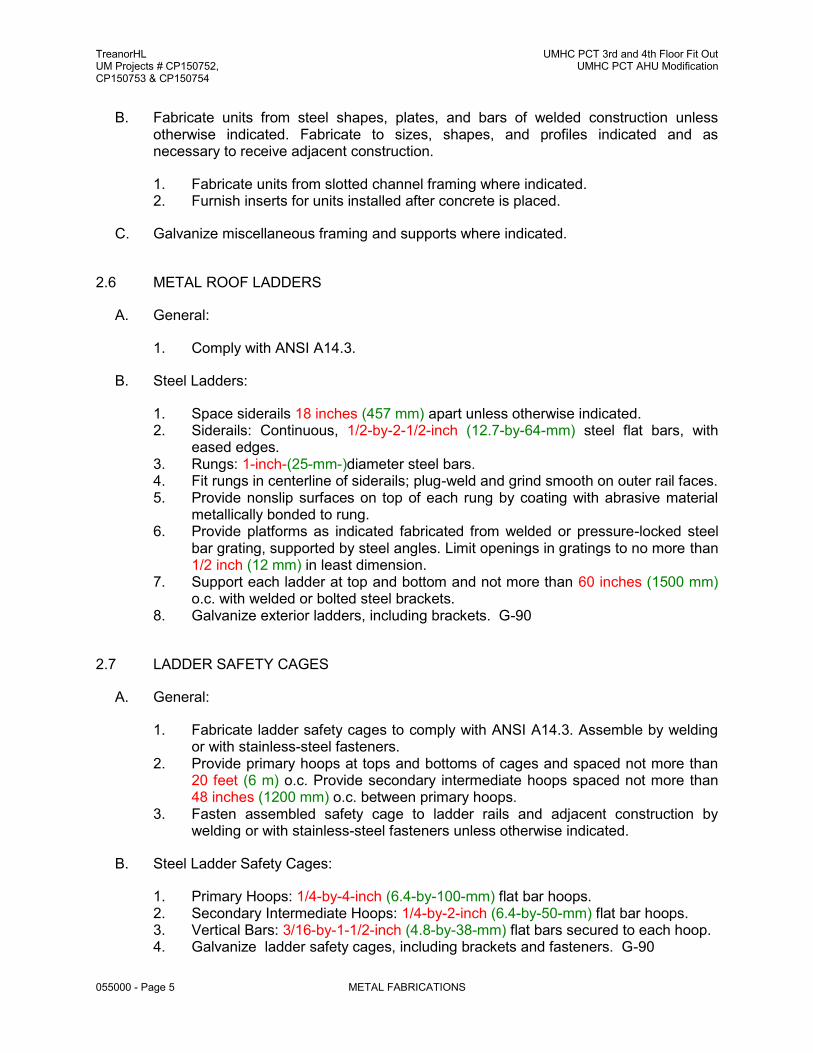
TreanorHL UM Projects # CP150752, CP150753 & CP150754
UMHC PCT 3rd and 4th Floor Fit Out UMHC PCT AHU Modification
055000 - Page 5 METAL FABRICATIONS
B. Fabricate units from steel shapes, plates, and bars of welded construction unless otherwise indicated. Fabricate to sizes, shapes, and profiles indicated and as necessary to receive adjacent construction.
1. Fabricate units from slotted channel framing where indicated. 2. Furnish inserts for units installed after concrete is placed.
C. Galvanize miscellaneous framing and supports where indicated.
2.6 METAL ROOF LADDERS
A. General:
1. Comply with ANSI A14.3.
B. Steel Ladders:
1. Space siderails 18 inches (457 mm) apart unless otherwise indicated. 2. Siderails: Continuous, 1/2-by-2-1/2-inch (12.7-by-64-mm) steel flat bars, with
eased edges. 3. Rungs: 1-inch-(25-mm-)diameter steel bars. 4. Fit rungs in centerline of siderails; plug-weld and grind smooth on outer rail faces. 5. Provide nonslip surfaces on top of each rung by coating with abrasive material
metallically bonded to rung. 6. Provide platforms as indicated fabricated from welded or pressure-locked steel
bar grating, supported by steel angles. Limit openings in gratings to no more than 1/2 inch (12 mm) in least dimension.
7. Support each ladder at top and bottom and not more than 60 inches (1500 mm) o.c. with welded or bolted steel brackets.
8. Galvanize exterior ladders, including brackets. G-90
2.7 LADDER SAFETY CAGES
A. General:
1. Fabricate ladder safety cages to comply with ANSI A14.3. Assemble by welding or with stainless-steel fasteners.
2. Provide primary hoops at tops and bottoms of cages and spaced not more than 20 feet (6 m) o.c. Provide secondary intermediate hoops spaced not more than 48 inches (1200 mm) o.c. between primary hoops.
3. Fasten assembled safety cage to ladder rails and adjacent construction by welding or with stainless-steel fasteners unless otherwise indicated.
B. Steel Ladder Safety Cages:
1. Primary Hoops: 1/4-by-4-inch (6.4-by-100-mm) flat bar hoops. 2. Secondary Intermediate Hoops: 1/4-by-2-inch (6.4-by-50-mm) flat bar hoops. 3. Vertical Bars: 3/16-by-1-1/2-inch (4.8-by-38-mm) flat bars secured to each hoop. 4. Galvanize ladder safety cages, including brackets and fasteners. G-90

TreanorHL UM Projects # CP150752, CP150753 & CP150754
UMHC PCT 3rd and 4th Floor Fit Out UMHC PCT AHU Modification
055000 - Page 6 METAL FABRICATIONS
2.8 PENTHOUSE ALUMINUM STAIRCASES AND HANDRAILS 1. General:
a. Provide pre-fabricated 16-gauge aluminum staircase and handrail assemblies where shown on documents. Provide roof pads beneath rails to protect roof. Attach securely to the Penthouse wall. Determine tread and riser heights after new roofline and sill elevation of penthouse have been determined by new roofing installation.
b. Utilize a company that can provide complete shop design and fabrication for OSHA compliant combination stair and handrail assemblies for the interior and exterior man doors of the new penthouse. 1) Shop Drawings for Owner / Architect review 2) 10 – year warranty 3) 400 lbs. minimum service rating
2. Manufacturers capable of providing services and equipment: a. ERETASTEP – 888.878.1839 b. Approved Equal
2.9 HORIZONTAL CABLE LIFE LINE AND FALL PROTECTION SYSTEM 1. General:
a. Provide OSHA compliant fall arrest system for the following conditions: 1) New Penthouse Roof – refer to plan for proposed locations 2) Existing Penthouse Roof – refer to plan for proposed locations
b. Utilize a company that can provide a third-party safety design for both conditions to include: 1) Full fall arrest safety design services including shop drawings for
Owner / Architect review. 2) Professional Engineers seal / signature for the State of Missouri for
final design documents. 3) On-Site testing of installed system mount points. 4) Manual for proper usage of system as part of close-out documents 5) 10- year Warranty 6) 1st and 2nd year OSHA pull testing
2. Manufacturers capable of providing services and equipment: a. Summit Anchor Company, Inc – 800.372.1098 / 301.620.8820 b. Flexible Lifeline Systems – 800.353.9425 c. ProBel – 800.461.0575 d. Approved equal
2.10 MISCELLANEOUS STEEL TRIM
A. Unless otherwise indicated, fabricate units from steel shapes, plates, and bars of profiles shown with continuously welded joints and smooth exposed edges. Miter corners and use concealed field splices where possible.
B. Provide cutouts, fittings, and anchorages as needed to coordinate assembly and installation with other work.

TreanorHL UM Projects # CP150752, CP150753 & CP150754
UMHC PCT 3rd and 4th Floor Fit Out UMHC PCT AHU Modification
055000 - Page 7 METAL FABRICATIONS
1. Provide with integrally welded steel strap anchors for embedding in concrete or masonry construction.
2.11 FINISHES, GENERAL
A. Finish metal fabrications after assembly.
B. Finish exposed surfaces to remove tool and die marks and stretch lines, and to blend into surrounding surface.
2.12 STEEL AND IRON FINISHES
A. Galvanizing: Hot-dip galvanize items as indicated to comply with ASTM A 153/A 153M for steel and iron hardware and with ASTM A 123/A 123M for other steel and iron products.
1. Do not quench or apply post galvanizing treatments that might interfere with paint adhesion.
B. Shop prime iron and steel items not indicated to be galvanized unless they are to be embedded in concrete, sprayed-on fireproofing, or masonry, or unless otherwise indicated.
C. Preparation for Shop Priming: Prepare surfaces to comply with SSPC-SP 6/NACE No. 3, "Commercial Blast Cleaning."
1. Exterior Items: SSPC-SP 6/NACE No. 3, "Commercial Blast Cleaning." 2. Items Indicated to Receive Zinc-Rich Primer: SSPC-SP 6/NACE No. 3,
"Commercial Blast Cleaning." 3. Items Indicated to Receive Primers Specified in Section 099600 "High-
Performance Coatings": SSPC-SP 6/NACE No. 3, "Commercial Blast Cleaning." 4. Other Items: SSPC-SP 3, "Power Tool Cleaning."
D. Shop Priming: Apply shop primer to comply with SSPC-PA 1, "Paint Application Specification No. 1: Shop, Field, and Maintenance Painting of Steel," for shop painting.
1. Stripe paint corners, crevices, bolts, welds, and sharp edges.
PART 3 - EXECUTION
3.1 INSTALLATION, GENERAL
A. Cutting, Fitting, and Placement: Perform cutting, drilling, and fitting required for installing metal fabrications. Set metal fabrications accurately in location, alignment, and elevation; with edges and surfaces level, plumb, true, and free of rack; and measured from established lines and levels.
B. Fit exposed connections accurately together to form hairline joints. Weld connections that are not to be left as exposed joints but cannot be shop welded because of shipping size limitations. Do not weld, cut, or abrade surfaces of exterior units that have been hot-dip galvanized after fabrication and are for bolted or screwed field connections.

TreanorHL UM Projects # CP150752, CP150753 & CP150754
UMHC PCT 3rd and 4th Floor Fit Out UMHC PCT AHU Modification
055000 - Page 8 METAL FABRICATIONS
C. Field Welding: Comply with the following requirements:
1. Use materials and methods that minimize distortion and develop strength and corrosion resistance of base metals.
2. Obtain fusion without undercut or overlap. 3. Remove welding flux immediately. 4. At exposed connections, finish exposed welds and surfaces smooth and blended
so no roughness shows after finishing and contour of welded surface matches that of adjacent surface.
D. Fastening to In-Place Construction: Provide anchorage devices and fasteners where metal fabrications are required to be fastened to in-place construction. Provide threaded fasteners for use with concrete and masonry inserts, toggle bolts, through bolts, lag screws, wood screws, and other connectors.
E. Provide temporary bracing or anchors in formwork for items that are to be built into concrete, masonry, or similar construction.
3.2 INSTALLING MISCELLANEOUS FRAMING AND SUPPORTS
A. General: Install framing and supports to comply with requirements of items being supported, including manufacturers' written instructions and requirements indicated on Shop Drawings.
B. Anchor supports for overhead doors securely to, and rigidly brace from, building structure.
C. Support steel girders on solid grouted masonry, concrete, or steel pipe columns. Secure girders with anchor bolts embedded in grouted masonry or concrete or with bolts through top plates of pipe columns.
1. Where grout space under bearing plates is indicated for girders supported on concrete or masonry, install as specified in "Installing Bearing and Leveling Plates" Article.
D. Install pipe columns on concrete footings with grouted baseplates. Position and grout column baseplates as specified in "Installing Bearing and Leveling Plates" Article.
1. Grout baseplates of columns supporting steel girders after girders are installed and leveled.
END OF SECTION 055000

TreanorHL UM Projects # CP150752, CP150753 & CP150754
UMHC PCT 3rd and 4th Floor Fit Out UMHC PCT AHU Modification
061000 - Page 1 Carpentry, General
SECTION 061000 - CARPENTRY, GENERAL
PART 1 - GENERAL
1.1 RELATED DOCUMENTS
A. Drawings and general provisions of the Contract, including General and Supplementary Conditions and Division 1 Specification Sections apply to this Section.
1.2 SUMMARY:
A. This Section includes, but is not necessarily limited to the following:
1. Wood nailers, framing, grounds, and blocking.
2. Miscellaneous interior and exterior plywood applications.
1.3 CODES AND STANDARDS:
A. Lumber Standards: Comply with PS 20 "American Softwood Lumber Standard" and with
applicable rules of the respective grading and inspecting agencies for species and products indicated.
B. Plywood Products Standards: Comply with PS 1 (ANSI A 199.1) or, for products not
manufactured under PS 1 provisions, with applicable APA Performance standard for type of panel indicated.
1.4 QUALITY ASSURANCE:
A. Single-Source Responsibility for Fire Retardant Treated Wood: Obtain each type of fire-
retardant-treated wood products from one source for both treatment and fire-retardant formulation.
B. Grade Stamps: Provide lumber with each piece factory-marked with grade stamp of
inspection agency evidencing compliance with grading rule requirements and identifying grading agency, grade, species, moisture content at time of surfacing, and mill.
1.5 SUBMITTALS:
A. Product Data: For each type of process and factory-fabricated product. Indicate
component materials and dimensions and include construction and application details.
1. Include data for wood-preservative treatment from chemical treatment manufacturer and certification by treating plant that treated materials comply with requirements. Indicate type of preservative used and net amount of preservative retained.
2. Include data for fire-retardant treatment from chemical treatment manufacturer
and certification by treating plant that treated materials comply with requirements. Include physical properties of treated materials based on testing by a qualified independent testing agency.

TreanorHL UM Projects # CP150752, CP150753 & CP150754
UMHC PCT 3rd and 4th Floor Fit Out UMHC PCT AHU Modification
061000 - Page 2 Carpentry, General
3. For fire-retardant treatments, include physical properties of treated lumber both before and after exposure to elevated temperatures, based on testing by a qualified independent testing agency according to ASTM D 5664.
4. For products receiving a waterborne treatment, include statement that
moisture content of treated materials was reduced to levels specified before shipment to Project site.
5. Include copies of warranties from chemical treatment manufacturers for
each type of treatment.
1.6 DELIVERY, STORAGE, AND HANDLING
A. Stack lumber flat with spacers beneath and between each bundle to provide air circulation. Protect lumber from weather by covering with waterproof sheeting, securely anchored. Provide for air circulation around stacks and under coverings.
PART 2 - PRODUCTS
2.1 MATERIALS:
A. Lumber, General:
1. Factory-mark each piece of lumber with type, grade, mill and grading
agency, except omit marking from surfaces to be exposed with transparent finish or without finish.
2. Nominal sizes are indicated, except as shown by detail dimensions.
3. Provide dressed lumber, surfaced four sides.
4. Provide seasoned lumber with 19% maximum moisture content at time
of dressing.
5. Species: Any of the following species: Spruce, pine or fir.
B. Miscellaneous Lumber:
1. Provide wood for support or attachment of other work including nailers, blocking, grounds, furring, and similar members. Provide lumber of sizes indicated, worked into shapes shown, and as follows:
2. Moisture content: 19% maximum for lumber items not specified to receive
wood preservative treatment.
C. Plywood:
1. Trademark: Identify each plywood panel with appropriate APA trademark.
2. For interior backing panels applications, and for miscellaneous interior applications, provide fire-retardant treated plywood with grade designation, APA C-D PLUGGED INT with exterior glue, in thickness indicated, or, if not otherwise indicated, not less than 3/4".
3. For miscellaneous exterior applications, provide plywood with grade designation,
APA C-C PLUGGED EXT, in thickness indicated.

TreanorHL UM Projects # CP150752, CP150753 & CP150754
UMHC PCT 3rd and 4th Floor Fit Out UMHC PCT AHU Modification
061000 - Page 3 Carpentry, General
D. Miscellaneous Materials:
1. Fasteners and Anchorages: Provide size, type, material and finish as indicated and as recommended by applicable standards, complying with applicable Federal Specifications for nails, staples, screws, bolts, nuts, washers and anchoring devices.
a. Where rough carpentry work is exposed to weather, in ground contact, or
in area of high relative humidity, provide fasteners and anchorages with a hot-dip zinc coating (ASTM A 153).
2. Screws (for attachment of plywood to framing and supports): Self-drilling, self-
tapping screws with countersunk type heads. Finish: Galvanized. Provide stainless steel screws for use with fire treated lumber and plywood.
2.2 WOOD TREATMENT:
A. Preservative Treatment by Pressure Process: AWPA U1; Use Category UC3b for exterior
construction not in contact with the ground, and Use Category UC4a for items in contact with the ground].
1. Preservative Chemicals: Acceptable to authorities having jurisdiction and
containing no arsenic or chromium.
2. Kiln-dry lumber after treatment to a maximum moisture content of 19 percent. Do not use material that is warped or that does not comply with requirements for untreated material.
3. Mark lumber with treatment quality mark of an inspection agency approved by
the ALSC Board of Review.
4. Complete fabrication of treated items prior to treatment, where possible. If cut after treatment, coat cut surfaces with heavy brush coat of same chemical used for treatment. Inspect each piece of lumber or plywood after drying and discard damaged or defective pieces.
5. Application: Treat items indicated on Drawings, and the following:
a. Wood nailers blocking, furring, and similar concealed members built into
or in contract with masonry or concrete.
B. Fire-Retardant-Treated Lumber and Plywood by Pressure Process: Products with a flame spread index of 25 or less when tested according to ASTM E 84, and with no

TreanorHL UM Projects # CP150752, CP150753 & CP150754
UMHC PCT 3rd and 4th Floor Fit Out UMHC PCT AHU Modification
061000 - Page 4 Carpentry, General
evidence of significant progressive combustion when the test is extended an additional 20 minutes, and with the flame front not extending more than 10.5 feet (3.2 m) beyond the centerline of the burners at any time during the test.
1. Use treatment that does not promote corrosion of metal fasteners.
2. Exterior Type: Treated materials shall comply with requirements specified above
for fire-retardant-treated lumber and plywood by pressure process after being subjected to accelerated weathering according to ASTM D 2898. Use for exterior locations and where indicated.
3. Interior Type A: Treated materials shall have a moisture content of 28 percent or
less when tested according to ASTM D 3201 at 92 percent relative humidity. Use where exterior type is not indicated.
C. Kiln-dry lumber after treatment to a maximum moisture content of 19 percent. Kiln-dry
plywood after treatment to a maximum moisture content of 15 percent.
D. Identify fire-retardant-treated wood with appropriate classification marking of qualified testing agency.
E. For exposed items, use chemical formulations that do not bleed through, contain
colorants, or otherwise adversely affect finishes
F. Fire-Retardant Treatment Application: All nailers, blocking, plywood and similar members which are permanently installed within the interior portion of the building, and all exterior nailers, blocking, plywood and similar members in connection with membrane roofing, metal roof, flat seam wall panels, flashing and sheet metal shall be fire retardant treated.
1. Fire retardant treatment shall not contain halogens, sulfates, chlorides or
ammonium phosphates.
2. Treatment shall be non-hygroscopic, and non-corrosive per ASTM D-3201.
3. Provide UL label on each piece of fire-retardant lumber or plywood.
4. Inspect each piece of treated lumber or plywood after drying and discard damaged or defective pieces.
PART 3 - EXECUTION
3.1 PRODUCT HANDLING:
A. Delivery and Storage: Keep materials dry at all times. Protect against exposure to
weather and contact with damp or wet surfaces. Stack lumber and plywood, and provide air circulation within stacks.
3.2 JOB CONDITIONS:
A. Coordination: Fit carpentry work to other work; scribe and cope as required for accurate
fit. Correlate location of furring, nailers, blocking, grounds and similar supports to allow proper attachment of other work.

TreanorHL UM Projects # CP150752, CP150753 & CP150754
UMHC PCT 3rd and 4th Floor Fit Out UMHC PCT AHU Modification
061000 - Page 5 Carpentry, General
3.3 INSTALLATION:
A. General:
1. Discard units of material with defects which might impair quality of work, and units which are too small to fabricate work with minimum joints or optimum joint arrangement.
2. Set carpentry work accurately to required levels and lines, with members plumb
and true and accurately cut and fitted.
3. Securely attach carpentry work to substrate by anchoring and fastening as shown and as required by recognized standards. Countersink nail heads on exposed carpentry work and fill holes.
4. Use common wire nails, except as otherwise indicated. Select fasteners of size
that will not penetrate members where opposite side will be exposed to view or will receive finish materials. Make tight connections between members. Install fasteners without splitting of wood; predrill as required.
B. Wood Nailers, and Blocking:
1. Provide wherever shown and where required for attachment of other work. Form
to shapes as shown and cut as required for true line and level of work to be attached. Coordinate location with other work involved.
2. Attach to substrates as required to support applied loading. Countersink bolts
and nuts flush with surfaces, unless otherwise shown. Build into masonry during installation of masonry work. Where possible, anchor to formwork before concrete placement.
3. Do not bridge expansion joints with wood blocking or plywood. Provide space
between blocking and plywood to coincide with the joint width of expansion joints.
C. Installation of Plywood:
A. General: Comply with applicable recommendations contained in APA
"Design/Construction Guide Residential & Commercial", for types of applications indicated.
B. Plywood: Screw to metal and wood supports; expansion plugs and screws to
concrete and masonry.
END OF SECTION 061000

THIS PAGE INTENTIONALLY LEFT BLANK

TreanorHL UM Projects # CP150752, CP150753 & CP150754
UMHC PCT 3rd and 4th Floor Fit Out UMHC PCT AHU Modification
064023 - Page 1 Casework and Millwork
SECTION 064023 - CASEWORK AND MILLWORK PART 1 - GENERAL
1.1 RELATED DOCUMENTS
A. Drawings and general provisions of the Contract, including General and
Supplementary Conditions and Division 1 Specification Sections apply to this Section.
1.2 SUMMARY:
A. Extent of casework/millwork is shown on drawings.
1. Types of work under this section includes, but is not limited to the
following:
a. Plastic laminate casework and millwork.
b. Metal clad casework and millwork.
c. Millwork and casework hardware.
d. Plastic laminate panels. 1.3 QUALITY ASSURANCE:
A. Quality Standards: Except as otherwise shown or specified, comply with
specified provisions of the following:
1. North American Architectural Woodwork Standards – Most recent version in print at the time of the contract execution.
B. Woodwork shall be produced in strict accordance with the Premium Grade
requirements of the Quality Standards of the Woodwork Institute (WI). The woodwork manufacturer agrees to a detailed review and approval of submittals and completed work for compliance to the Premium Grade standards of the WI by the Architect. If the Architect disputes compliance with the Quality Standards, the woodwork company agrees to remedy the problems bound by the decision of an independent mediator (selected by the WI) and the Architect.
C. Fabricator: Work shall be executed by a recognized architectural woodworking
company who can furnish supporting documentation that the firm has been continuously employed for a minimum of ten (10) years on projects of similar size and quality to this project, and with adequate engineering, production, and financial capability to produce this job without causing delay.
TreanorHL UM Projects # CP150752, CP150753 & CP150754
UMHC PCT 3rd and 4th Floor Fit Out UMHC PCT AHU Modification
064023 - Page 2 Casework and Millwork
D. Casework and millwork shall be furnished by a single-source manufacturer in order to provide undivided responsibility for all woodwork including fabrication and finishing.
E. Measurements: Before proceeding with fabrication of casework and millwork
required to be fitted to other construction, obtain measurements and verify dimensions and shop drawings details for accurate fit.
1. Where sequence of measuring substrates before fabrication would
delay the project, proceed with fabrication (without field measurements) and provide ample borders and edges to allow for subsequent scribing and trimming of casework and millwork for accurate fit.
1.4 REFERENCES:
1. North American Architectural Woodwork Standards – Most recent
version in print at the time of the contract execution.
1.5 SUBMITTALS:
A. Shop Drawings: Submit shop drawings showing location of each item, dimensioned plans and elevations, large scale details, attachment devices and other components.
B. Samples: Submit the following samples:
1. Plastic laminate 12" square for each type and surface finish.
2. Exposed cabinet hardware, one unit of each type and finish.
C. Samples: Submit for approval 12" long samples of each color required (except black) for each type of sealant and caulking compound exposed to view.
1.6 PRODUCT DELIVERY, STORAGE AND HANDLING:
A. Protect all items during transit, delivery, storage and handling to prevent
damage, soiling and deterioration.
B. Do not deliver items, until painting, wet work, and similar operations which could damage, soil or deteriorate woodwork have been completed in installation areas. If, due to unforeseen circumstances, items must be stored in other than installation areas, store only in areas meeting requirements specified for installation areas.
1.7 JOB CONDITIONS:
A. Conditioning: Fabricator and installer shall advise Contractor of temperature and humidity requirements for millwork/casework installation areas. Do not install items until required temperature and relative humidity have been stabilized and will be maintained in installation areas.

TreanorHL UM Projects # CP150752, CP150753 & CP150754
UMHC PCT 3rd and 4th Floor Fit Out UMHC PCT AHU Modification
064023 - Page 3 Casework and Millwork
B. Maintain temperature and humidity in installation area as required to maintain moisture content of installed work within a 1.0 percent tolerance of optimum moisture content, from date of installation through remainder of construction period. The fabricator of millwork/casework shall determine optimum moisture content and required temperature and humidity conditions.
PART 2 - PRODUCTS
2.1 MATERIALS:
A. Plastic Laminate: Comply with the requirements of "Publication No. LD3" by the National Electrical Manufacturer's Association (NEMA) for the following:
1. General Purpose Laminate: NEMA General-purpose type, Grade GP-
50, nominal 0.050" thickness for horizontal surfaces, and GP-28, nominal 0.028 thickness for vertical surfaces.
2. Surface Finish and Colors: Provide color and surface finish as
determined by the Architect.
3. Finish: Low reflective, unless otherwise indicated or scheduled.
4. Colors: Refer to the “Finish Legend”. Color of plastic laminate used in conjunction with adjustable shelving shall match Nevamar “57027T Smoky White” as approved by the Architect.
B. Core (For plastic laminate and wood veneer):
1. Medium density fiberboard, free of formaldehyde resin, having a
density of not less than 48 lbs./cu. ft., and complying with ASTM D 1037. All tops and counter tops shall be hardwood faced exterior grade plywood.
2. Fire Rated Core (For Fabrication of Panels Installed in Patient Rooms)
a. Fire retardant treated medium density fiberboard, free of
formaldehyde resins, having a flame spread rating of not more than 25 when tested in accordance with ASTM E 84. Each panel shall bear the label of Underwriters' Laboratories, Inc. Products: Provide one of the following:
1) "PyroBlock", by Panel Resource. 2) "Medite FR2", Sierra Pine Composite Solutions.
C. Finish Hardware and Related Accessories: Provide hardware and related
accessories as follows and as indicated on the drawings. Finish for exposed hardware shall be as selected by the Architect, unless otherwise indicated.
1. Hinges:
a. Concealed Hinges: Concealed, self-closing type hinges of
type required by door construction and stile applications. Number of hinges required per leaf shall be determined by door size and weight.

TreanorHL UM Projects # CP150752, CP150753 & CP150754
UMHC PCT 3rd and 4th Floor Fit Out UMHC PCT AHU Modification
064023 - Page 4 Casework and Millwork
b. Swing-Up Hinges: Haffele “E-Z Open” spring piston type hinge of type required for size and weight of door being opened. Provide two for PT1251 and two for PT1252.
c. Hinges: ANSI/BHMA A 156.9, Grade 1. institutional
construction, 5 knuckles, 2-1/2" long; heavy, brush chrome plated with hinge barrel only projected beyond face of cabinet. Furnish two per door 36" high and less, three per door over 36" high. Hinges shall be equal to “376” by Rockford Process Controls.
2. Locks: Pin tumbler, solid brass cylinder cam locks, of type required by door and drawer applications, with 3/4" round cylinder. Locks shall be keyed as directed by the Owner. Provide locks on all doors and drawers not occurring behind doors. Manufacturer: CompX National, or approved equal.
3. Keypad Locks: Provide “DaulAxess” by CompX Security Products,
surface recessed mounted or approved equal on all drawers and doors (U.N.O.) at the following locations:
a. ALC-NOUR/VEND, PUB b. ALC-NOUR, PUB c. MED d. WKRM-ANES e. CLEAN CORE PT3220 f. CLEAN/MED PT2249 g PT2005F PASS (EFCC Lab), tall cabinets only
4. Drawer Slides: Ball bearing type with nickel plated, carburized steel balls. Ball retainers shall be bridge type, self-cleaning, slide shall have positive stop at full extension and permit the removal of the drawer without use of tools. Load capacity shall be 75 lbs. per pair. Provide drawer slides as manufactured by Accuride.
5. Drawer Slides: Ball bearing type with nickel plated, carburized steel
balls. Ball retainers shall be bridge type, self-cleaning, slide shall have positive stop at full extension and permit the removal of the drawer without use of tools. Load capacity shall be 75 lbs. per pair. Provide drawer slides as manufactured by Accuride.
6. Shelf Standards and Brackets: ANSI A156, Type B84072 standards
and 824082 brackets. Standards shall be mortised into sides of cabinets.
7. Shelf Support Clips: Shelf supports shall be heavy-duty, 2 pin design to
prevent the shelf support from rotating.
8. Pulls: Refer to the following Hardware Groups noted on the millwork elevations.
9. Grommets: Provide “Max1” metal grommets of sizes as follows and
indicated as manufactured by Doug Mockett & Co., Inc. Color as selected by the Architect from manufacturer's full color range.
a. 27 5/8" overall fitting into slot 27 7/32" x 2 11/32"x 1 17/32" deep

TreanorHL UM Projects # CP150752, CP150753 & CP150754
UMHC PCT 3rd and 4th Floor Fit Out UMHC PCT AHU Modification
064023 - Page 5 Casework and Millwork
- between counter supports 36" and larger.
b. 13 7/8" overall fitting into slot 13 11/32" x 2 11/32" x 1 17/32" deep - between counter supports less than 36"apart.
10. Millwork Hardware
Groups: Hardware Group
Hardware Group 1 (TYP ) Hafele Stainless Steel Handles, 116.11.635
Hardware Group 2 (Level 4 Wait)
Siro Designs 45 European Railing Pull, Horizontal 31”
Hardware Group 3 (PAT RM wardrobe) Siro Designs 45 European Railing Pull, Vertical 31” Siro Designs 45 European Railing Pull, Horizontal 7” Siro Designs 45 European Railing Pull, Vertical 7” (Motor)
Hardware Group 4 (PAT RM nurse work)
Siro Designs 45 European Railing Pull, Vertical 10” Siro Designs 45 European Railing Pull, Horizontal 10”
Hardware Group 5 (BED FL CORR)
Siro Designs 45 European Railing Pull, Vertical 31” Hafele Aluminum Extruded Handles, 126.22.909 Horizontal
Hardware Group 6 (INF)
Siro Designs 45 European Railing Pull, Top Vertical 31” Siro Designs 45 European Railing Pull, Bottom Vertical 7”
Hardware Group 7(EXAM)
Siro Designs 45 European Railing Pull, Top Vertical 31” Siro Designs 45 European Railing Pull, Bottom Vertical 7”
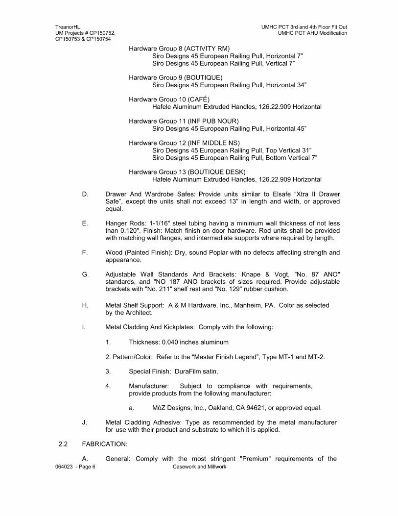
TreanorHL UM Projects # CP150752, CP150753 & CP150754
UMHC PCT 3rd and 4th Floor Fit Out UMHC PCT AHU Modification
064023 - Page 6 Casework and Millwork
Hardware Group 8 (ACTIVITY RM) Siro Designs 45 European Railing Pull, Horizontal 7” Siro Designs 45 European Railing Pull, Vertical 7”
Hardware Group 9 (BOUTIQUE)
Siro Designs 45 European Railing Pull, Horizontal 34”
Hardware Group 10 (CAFÉ) Hafele Aluminum Extruded Handles, 126.22.909 Horizontal
Hardware Group 11 (INF PUB NOUR)
Siro Designs 45 European Railing Pull, Horizontal 45”
Hardware Group 12 (INF MIDDLE NS) Siro Designs 45 European Railing Pull, Top Vertical 31” Siro Designs 45 European Railing Pull, Bottom Vertical 7”
Hardware Group 13 (BOUTIQUE DESK)
Hafele Aluminum Extruded Handles, 126.22.909 Horizontal
D. Drawer And Wardrobe Safes: Provide units similar to Elsafe “Xtra II Drawer Safe”, except the units shall not exceed 13” in length and width, or approved equal.
E. Hanger Rods: 1-1/16" steel tubing having a minimum wall thickness of not less
than 0.120". Finish: Match finish on door hardware. Rod units shall be provided with matching wall flanges, and intermediate supports where required by length.
F. Wood (Painted Finish): Dry, sound Poplar with no defects affecting strength and
appearance.
G. Adjustable Wall Standards And Brackets: Knape & Vogt, "No. 87 ANO" standards, and "NO 187 ANO brackets of sizes required. Provide adjustable brackets with "No. 211" shelf rest and "No. 129" rubber cushion.
H. Metal Shelf Support: A & M Hardware, Inc., Manheim, PA. Color as selected by the Architect.
I. Metal Cladding And Kickplates: Comply with the following:
1. Thickness: 0.040 inches aluminum
2. Pattern/Color: Refer to the “Master Finish Legend”, Type MT-1 and MT-2.
3. Special Finish: DuraFilm satin.
4. Manufacturer: Subject to compliance with requirements, provide products from the following manufacturer:
a. MóZ Designs, Inc., Oakland, CA 94621, or approved equal.
J. Metal Cladding Adhesive: Type as recommended by the metal manufacturer
for use with their product and substrate to which it is applied. 2.2 FABRICATION:
A. General: Comply with the most stringent "Premium" requirements of the

TreanorHL UM Projects # CP150752, CP150753 & CP150754
UMHC PCT 3rd and 4th Floor Fit Out UMHC PCT AHU Modification
064023 - Page 7 Casework and Millwork
Architectural Woodwork Institute (AWI) "Quality Standards" as a minimum level of quality standard for the fabrication of all work, except where more specific or more stringent requirements are specified herein.
B. Complete fabrication, including assembly and hardware application, before
shipment to project site to maximum extent possible. Disassemble components only as necessary for shipment and installation. Provide ample allowance for scribing, trimming, and fitting.
C. Equipment Openings: Coordinate the size of openings as required for built-
in equipment with the actual piece of equipment to be furnished.
D. Fabricate plastic laminate items to dimensions and profiles shown.
E. Assemble units in the shop in as large components as practicable to minimize field cutting and jointing; mortise and tenon, or glue and screw joints for maximum strength using precision jigs and clamps to insure square corners and plumb vertical surfaces. All bottoms of cabinets shall be flush for ease of cleaning.
F. Edges of drawer fronts and swing doors shall be square. All doors and
drawer fronts shall be cushioned with rubber bumpers applied on the back side.
G. Cabinet Body and Shelves: Fabricate from 3/4" thick medium density fiberboard with cabinet liner finish on semi-exposed surfaces, except where indicated as plastic laminate or wood. Provide shelves with color matched front and back 3 mm PVC edges.
H. Doors: 3/4" thick medium density fiberboard with plastic laminate cladding on
front, back and edges of door, except where indicated as wood.
I. Exposed bottoms of wall cabinets shall have laminate finish of same material used on exterior of cabinet.
J. Drawer sides and backs shall be 1/2" thick solid hardwood, clear and sound
two sides, of unselected color or figure or 7-ply all hardwood veneer core plywood (no voids). Sides shall be multiple dovetailed and glued to drawer fronts and backs.
K. Drawer bottoms shall be 3/16" thick tempered hardboard set up
approximately 5/16" from drawer sides. Bottoms shall be grooved 1/4" deep into drawer fronts, sides and backs.
L. Edge banding shall be provided on the following: All four sides of drawer
fronts and doors, and adjustable shelves; exposed edges of fixed shelving; exposed edges of cabinet, including those behind drawer fronts and swing doors.
1. Edge banding on plastic laminate items shall be accomplished with
3 mm PVC edging, except where indicated as wood. Cabinet fronts shall be edged with 1mm PVC.
2. Edge banding on natural finished wood items shall be accomplished
with the same wood used for face.
M. Closet and Adjustable Shelving: 3/4" thick plastic laminate faced plywood with plastic laminate edge banding on exposed edges.

TreanorHL UM Projects # CP150752, CP150753 & CP150754
UMHC PCT 3rd and 4th Floor Fit Out UMHC PCT AHU Modification
064023 - Page 8 Casework and Millwork
N. Plastic Laminate:
1. Plastic shall be laminated to core material under pressure with
hydraulic presses and cold setting glue.
2. Plastic laminate shall be applied to all exposed surfaces, and to the rear surfaces of doors and drawers. Balance of cabinets, etc. shall be finished with cabinet liner as specified for semi-exposed surfaces.
3. Balance unexposed surfaces of plastic laminate tops with 0.020"
backing sheet.
4. Surfaces requiring more than one sheet of plastic shall have the plastic pre-matched to minimize color variation and shall be fabricated from the longest sheet lengths available. Joints shall be neatly and tightly fitted.
O. Semi-Exposed Surfaces: Finish semi-exposed surfaces as follows:
1. Cab Liner
P. Metal Cladding:
1. Metal cladding shall be laminated to core material under pressure.
2. Surfaces requiring more than one sheet of metal shall have the metal pre-matched to minimize color variation and shall be fabricated from the longest sheet lengths available. Joints shall be neatly and tightly fitted.
3. Fabricate items in maximum lengths and keep joints to a minimum.
Form with flat, flush surfaces, true to line and level, and without cracking and grain separation at bends. Provide stiffeners or backing as required to produce surface flatness, free of oil-canning, and to impart sufficient strength for required use.
PART 3 - EXECUTION 3.1 PREPARATION:
A. Condition finish casework and millwork to average prevailing humidity
conditions in installation areas prior to installing. 3.2 INSTALLATION:
A. General: Comply with the most stringent "Premium" requirements of the
North American Architectural Woodwork Standards – Version 3.0 effective July 1, 2016.
B. Installation of Architectural Woodwork (Interior) as a minimum level of quality for installation of all casework and millwork, except where more specific or more stringent requirements are specified herein.
C. Install the work plumb, level, true and straight with no distortions. Shim as
required using concealed shims. Install to a tolerance of 1/8" in 8'-0" for
TreanorHL UM Projects # CP150752, CP150753 & CP150754
UMHC PCT 3rd and 4th Floor Fit Out UMHC PCT AHU Modification
064023 - Page 9 Casework and Millwork
plumb and level (including countertops); and with no offset in flush adjoining surface, and in revealed adjoining surfaces.
D. Scribe and cut work to fit adjoining work, and refinish cut surfaces or
repair damaged finish at cuts.
E. Casework: Install without distortion so that doors and drawers will fit openings properly and be accurately aligned. Adjust hardware to center doors and drawers in openings and to provide unencumbered operation. Complete the installation of hardware and accessory items as indicated. Maintain veneer sequence matching of casework with transparent finish.
F. Tops:
1. Field Jointing: Where practicable, make in same manner as factory jointing using dowels, splines, adhesives, and fasteners recommended by manufacturer. Locate field joints as shown on accepted shop drawings, factory prepared so that there is no job site processing to top and edge surfaces.
2. Workmanship: Abut top and edge surfaces in one true plane, with
internal supports placed to prevent any deflection. Provide flush hairline joints in top units. Scribe and cut for accurate fit.
a. After installation, carefully dress joints smooth, remove any surface
scratches, clean and polish entire surface.
b. Provide all holes and cutouts as required for built-in equipment, and mechanical and electrical service fixtures. Verify size of opening with actual size of equipment to be used, prior to making openings.
3. Secure tops with concealed fastening devices.
G. Hardware: Prepare wood door frames to receive finish hardware, including cutouts, and mortising, in accordance with final Finish Hardware Schedule and templates provided by hardware supplier.
3.3 ADJUSTMENT, CLEANING FINISHING AND PROTECTION:
A. Repair damaged and defective items wherever possible to eliminate defects
functionally and visually; where not possible to repair properly, replace items. Adjust joinery for uniform appearance.
B. Clean hardware, lubricate and make final adjustments for proper operation.
C. Clean finish millwork and casework on exposed and semi-exposed surfaces.
Touch-up shop applied finishes to restore damaged or soiled areas.
D. Protection: Cover completed work with 4-mil polyethylene film protective enclosure, applied in a manner which will allow easy removal and without damage to woodwork or adjoining work. Remove cover immediately before time of final acceptance.
END OF SECTION 064023

THIS PAGE INTENTIONALLY LEFT BLANK

TreanorHL UM Projects # CP150752, CP150753 & CP150754
UMHC PCT 3rd and 4th Floor Fit Out UMHC PCT AHU Modification
066155 - Page 1 Solid Polymer Fabrications
SECTION 066155 – SOLID POLYMER FABRICATIONS
PART 1 - GENERAL
1.1 RELATED DOCUMENTS
A. Drawings and general provisions of the Contract, including General and Supplementary Conditions and Division 1 Specification Sections apply to this Section.
1.2 SUMMARY:
A. Extent of solid polymer fabrications, referenced herein as resinous panel material, is
shown on the drawings and “Interior Finish And Material Schedule”.
B. Coordination of Fabrication: Wherever possible, check dimensions of supporting structure at the site by accurate field measurements before final submittal of shop drawings and fabrication of resinous panels material. However, coordinate fabrication schedule with construction progress as directed by the Contractor to avoid delay of the work. Where necessary, proceed without field measurements and coordinate installation tolerances to ensure proper fit.
1.3 QUALITY ASSURANCE:
A. Each type of solid polymer panel material shall be from the same production run to
assure uniformity in color and appearance.
B. Shop Assembly: Preassemble items in the shop to the greatest extent possible. Disassemble units only to the extent necessary for shipping and handling limitations. Clearly mark units for reassembly and coordinated installation.
C. Field Measurements: Take field measurements prior to preparation of shop drawings
and fabrication, where possible, to ensure proper fitting of the work. However, do not delay job progress; allow for trimming and fitting wherever the taking of field measurements before fabrication might delay the work.
1.4 SUBMITTALS:
A. Manufacturer's Data: Submit manufacturer's detailed materials and installation
specifications and other data for solid polymer material.
B. Samples: Submit sample not less than 6" x 6" in size of color, grade and finish of each type of solid polymer material required. Sample to include one joint showing method of jointing and finishing.
C. Samples: Submit for approval 12" long samples of each color required (except black) for
each type of sealant compound exposed to view.
D. Shop Drawings: Submit drawings showing size, dimensions, sections and the arrangement and provisions for jointing, anchoring, fastening and supports and other necessary details for reception of other work.
E. Maintenance Data: Submit manufacturer's care and maintenance data, including repair
and cleaning instructions for solid surface material.

TreanorHL UM Projects # CP150752, CP150753 & CP150754
UMHC PCT 3rd and 4th Floor Fit Out UMHC PCT AHU Modification
066155 - Page 2 Solid Polymer Fabrications
1.5 WARRANTY:
A. Provide manufacturer's warranty against defects in solid polymer material. Warranty
shall provide for replacement material and labor for a period of 5 years, beginning at Date of Substantial Completion.
1.6 DELIVERY, STORAGE AND HANDLING:
A. Protect work from damage during loading, shipment delivery and storage. Use non-
staining materials for blocking and packing. Stack units at the site in accordance with fabricator's recommendations.
PART 2 - PRODUCTS
2.1 MATERIALS:
A. Solid Polymer Materials (SPF): Refer to the "Master Finish Legend" for types, colors,
patterns and manufacturers, or an approved equal.
B. Adhesives And Sealants: Provide types as recommended by the respective manufacturer of resinous panel material.
C. Attachment Devices And Supports: Provide types as indicated on the drawings.
D. “J” Molding: Provide clear anodized extruded aluminum molding by Fry Reglet, or
approved equal. Coordinate the sizes required with the actual item to which it will be applied.
E. Suspended Hardware: Provide hardware as follows and manufactured by 3-Forms:
1. Cables: Nominal 3 mm diameter, galvanized steel cable. Each end of cable
shall be provided with a crimped on coupling for attachment to ceiling and floor.
2. Accessories: Provide all fittings and accessories necessary for the attachment of glass shelving, and for supporting, fastening and tensioning the cable display system. All fittings shall have a satin chrome finish. Refer to drawings for configuration and arrangement of cable display system and accessories. Provide "clamps for glass shelves single and double.
F. Framing System: “Frames” by 3forms, or approved equal.
1. Framing members, transition members, mullions and mountings for aluminum
framing, etc. shall be of extruded aluminum. Include all anchors, fasteners, hardware, etc., to provide a complete installation.
2. Joints in metal work: All exposed work shall be carefully matched to produce
continuity of line and design. All joints in exposed metal work, unless otherwise shown or specified, shall be accurately fitted and rigidly secured with hairline contact. All corner joints shall be mitered.
3. Prefabrication: To greatest extent possible, complete fabrication, assembly,
finishing, and other work before shipment to project site.
4. Continuity: Maintain accurate relation of planes and angles, with hairline fit of contacting members.
5. Finish: Manufacturer's standard painted system, in color as selected by the
TreanorHL UM Projects # CP150752, CP150753 & CP150754
UMHC PCT 3rd and 4th Floor Fit Out UMHC PCT AHU Modification
066155 - Page 3 Solid Polymer Fabrications
Architect. 2.2 FABRICATION:
A. General: Fabricate as shown. Cut accurately to shape and dimensions indicated.
Provide holes cut or drilled for anchors, fasteners, brackets as shown and as necessary to secure work in place.
B. No evidence of drilling, cutting or patching shall be exposed in the finished work. Allow
for expansion and contraction.
C. Finish on all exposed surfaces shall be a uniform finish as scheduled.
D. Edges not concealed by trim shall be polished. PART 3 - EXECUTION
3.1 INSTALLATION:
A. Install in accordance with fabricator's approved shop drawings.
B. Finished work shall be level, plumb and in correct relationship to adjacent work.
C. Form field joints using manufacturer's recommended adhesive, with joints inconspicuous
in finished work.
D. Keep components clean during installation. Remove adhesives, sealants and other stains. Replace stained components.
E. Protect surfaces from damage. Repair work or replace damaged work that cannot be
repaired to Architect's satisfaction.
F. Adjust cables for proper tension. Replace damaged or defective items.
END OF SECTION 066155

THIS PAGE INTENTIONALLY LEFT BLANK

TreanorHL UM Projects # CP150752, CP150753 & CP150754
UMHC PCT 3rd and 4th Floor Fit Out UMHC PCT AHU Modification
071800 - Page 1 TRAFFIC COATINGS
SECTION 071800 - TRAFFIC COATINGS
PART 1 - GENERAL
1.1 RELATED DOCUMENTS
A. Drawings and general provisions of the Contract, including General and Supplementary Conditions and Division 01 Specification Sections, apply to this Section.
1.2 SUMMARY
A. Section includes traffic coatings for the following applications:
1. Equipment-room floor. The new floor coating for the Penthouse requires removal of all roofing and roofing mastic currently in place. This work includes, but is not limited to, shot blasting of the deck surface. Fully comply with the product manufacturers requirements for installation of the new coating system.
B. Related Requirements:
1. Section 096723 "Resinous Flooring" for fluid-applied, high-performance resinous flooring that does not serve as a waterproofing membrane with integral wearing surface.
1.3 ACTION SUBMITTALS
A. Product Data: For each type of product, including installation instructions.
B. Shop Drawings: For traffic coatings.
1. Include details for treating substrate joints and cracks, flashings, deck penetrations, and other termination conditions.
C. Samples for Initial Selection: For each type of exposed finish.
D. Samples for Verification: For each type of exposed finish, prepared on rigid backing.
1. Provide stepped Samples on backing to illustrate buildup of traffic coatings.
1.4 INFORMATIONAL SUBMITTALS
A. Qualification Data: For Installer.
B. Product Certificates: For each type of traffic coating.

TreanorHL UM Projects # CP150752, CP150753 & CP150754
UMHC PCT 3rd and 4th Floor Fit Out UMHC PCT AHU Modification
071800 - Page 2 TRAFFIC COATINGS
C. Sample Warranty: For special warranty.
1.5 CLOSEOUT SUBMITTALS
A. Maintenance Data: For traffic coatings to include in maintenance manuals.
1.6 QUALITY ASSURANCE
A. Installer Qualifications: An authorized representative who is trained and approved by manufacturer.
1.7 FIELD CONDITIONS
A. Environmental Limitations: Apply traffic coatings within the range of ambient and substrate temperatures recommended in writing by manufacturer. Do not apply traffic coatings to damp or wet substrates, when temperatures are below 40 deg F (5 deg C), when relative humidity exceeds 85 percent, or when temperatures are less than 5 deg F (3 deg C) above dew point.
1. Do not apply traffic coatings in snow, rain, fog, or mist, or when such weather conditions are imminent during the application and curing period. Apply only when frost-free conditions occur throughout the depth of substrate.
B. Do not install traffic coating until items that penetrate membrane have been installed.
1.8 WARRANTY
A. Manufacturer's Warranty: Manufacturer agrees to repair or replace traffic coating that fails in materials or workmanship within specified warranty period.
1. Failures include, but are not limited to, the following:
a. Adhesive or cohesive failures. b. Abrasion or tearing failures. c. Surface crazing or spalling. d. Intrusion of water, oils, gasoline, grease, salt, deicer chemicals, or acids
into deck substrate.
2. Warranty Period: Five years from date of Substantial Completion.
PART 2 - PRODUCTS
2.1 MATERIALS, GENERAL
A. Material Compatibility: Provide primers; base-, intermediate-, and topcoat; and accessory materials that are compatible with one another and with substrate under conditions of service and application, as demonstrated by manufacturer based on testing and field experience.
B. Source Limitations:

TreanorHL UM Projects # CP150752, CP150753 & CP150754
UMHC PCT 3rd and 4th Floor Fit Out UMHC PCT AHU Modification
071800 - Page 3 TRAFFIC COATINGS
1. Obtain traffic coatings from single source from single manufacturer. 2. Obtain primary traffic-coating materials, including primers, from traffic-coating
manufacturer. Obtain accessory materials including aggregates, sheet flashings, joint sealants, and substrate repair materials of types and from sources recommended in writing by primary material manufacturer.
2.2 TRAFFIC COATING for New Penthouse Floor
A. Traffic Coating: Manufacturer's standard, traffic-bearing, seamless, high-solids-content, cold liquid-applied, elastomeric, waterproofing membrane system with integral wearing surface for equipment-room floor; according to ASTM C 957.
1. Manufacturers: Subject to compliance with requirements, provide products by the following:
2. Basis-of-Design Product: Subject to compliance with requirements, provide Insert manufacturer's name; product name or designation or comparable product by one of the following:
a. Tremco - Commercial Sealants and Waterproofing
1) Vulkem EWS with PUMA Technology (Heavy Duty)
B. PRIOR TO COMMENCING FLOOR COATING INSTALL, ALL ROOFING RESIDUE SHALL BE BEAD BLASTED OFF TO PROPERLY PREPARE THE DECK SURFACE FOR NEW FINISH.
C. Primer: Liquid solvent-borne primer recommended for substrate and conditions by traffic-coating manufacturer.
1. Material: Urethane.
a. Tremco PUMA Primer
D. Preparatory and Base Coats: Polyurethane.
1. Thicknesses: Minimum dry film thickness as recommended in writing by manufacturer for substrate and service conditions indicated.
2. Tremco PUMA BC (Base Coat)
E.
1. Tremco PUMA WCIntermediate Coat: Polyurethane. 2. Thicknesses: Minimum wet film thickness as recommended in writing by
manufacturer for substrate and service conditions indicated, measured excluding aggregate.
3. Aggregate Content: As recommended in writing by traffic-coating manufacturer for substrate and service conditions indicated.
F.

TreanorHL UM Projects # CP150752, CP150753 & CP150754
UMHC PCT 3rd and 4th Floor Fit Out UMHC PCT AHU Modification
071800 - Page 4 TRAFFIC COATINGS
1. Tremco PUMA TCTopcoat: Polyurethane. 2. Thicknesses: Minimum wet film thickness as recommended in writing by
manufacturer for substrate and service conditions indicated, measured excluding aggregate.
3. Aggregate Content: As recommended in writing by traffic-coating manufacturer for substrate and service conditions indicated.
4. Color: As selected by Architect from manufacturer's full range.
G. Aggregate: Manufacturer's standard aggregate for each use indicated of particle sizes, shape, and minimum hardness recommended in writing by traffic-coating manufacturer.
H. Fire-Test-Response Characteristics: Provide traffic-coating materials with the fire-test-response characteristics as determined by testing identical products per test method below for deck type and slopes indicated by an independent testing and inspecting agency that is acceptable to authorities having jurisdiction.
1. Class A roof covering per ASTM E 108 or UL 790.
I. VOC Content: Traffic coating shall have a VOC content of 150 g/L or less when calculated according to 40 CFR 59, Subpart D (EPA Method 24).
2.3 ACCESSORY MATERIALS
A. Joint Sealants: As specified in Section 079200 "Joint Sealants."
B. Adhesive: Contact adhesive recommended in writing by traffic-coating manufacturer.
C. Reinforcing Strip: Fiberglass mesh recommended in writing by traffic-coating manufacturer.
PART 3 - EXECUTION
3.1 EXAMINATION
A. Examine substrates, areas, and conditions, with Installer present, for compliance with requirements for surface smoothness, surface moisture, and other conditions affecting performance of traffic-coating work.
B. Verify that substrates are visibly dry and free of moisture.
1. Test for moisture according to ASTM D 4263. 2. Test for moisture content by method recommended in writing by traffic-coating
manufacturer.
C. Prepare written report, endorsed by Installer, listing conditions detrimental to performance of traffic-coating work.
D. Proceed with installation only after substrate construction and penetrating work have been completed and unsatisfactory conditions have been corrected.

TreanorHL UM Projects # CP150752, CP150753 & CP150754
UMHC PCT 3rd and 4th Floor Fit Out UMHC PCT AHU Modification
071800 - Page 5 TRAFFIC COATINGS
1. Begin coating application only after minimum concrete-curing and -drying period recommended in writing by traffic-coating manufacturer has passed and after substrates are dry.
2. Application of coating indicates acceptance of surfaces and conditions.
3.2 PREPARATION
A. General: Before applying traffic coatings, clean and prepare substrates according to ASTM C 1127 and manufacturer's written instructions to produce clean, dust-free, dry substrate for traffic-coating application. Remove projections, fill voids, and seal joints if any, as recommended in writing by traffic-coating manufacturer.
B. Schedule preparation work so dust and other contaminants from process do not fall on wet, newly coated surfaces.
C. Mask adjoining surfaces not receiving traffic coatings to prevent overspray, spillage, leaking, and migration of coatings. Prevent traffic-coating materials from entering deck substrate penetrations and clogging weep holes and drains.
D. Concrete Substrates: Mechanically abrade surface to a uniform profile acceptable to manufacturer, according to ASTM D 4259. Do not acid etch.
1. Remove grease, oil, paints, and other penetrating contaminants from concrete. 2. Remove concrete fins, ridges, and other projections. 3. Remove laitance, glaze, efflorescence, curing compounds, concrete hardeners,
form-release agents, and other incompatible materials that might affect coating adhesion.
4. Remove remaining loose material to provide a sound surface, and clean surfaces according to ASTM D 4258.
3.3 TERMINATIONS AND PENETRATIONS
A. Prepare vertical and horizontal surfaces at terminations and penetrations through traffic coatings and at expansion joints, drains, and sleeves according to ASTM C 1127 and manufacturer's written instructions.
B. Provide sealant cants at penetrations and at reinforced and nonreinforced, deck-to-wall butt joints.
C. Terminate edges of deck-to-deck expansion joints with preparatory base-coat strip.
3.4 JOINT AND CRACK TREATMENT
A. Prepare, treat, rout, and fill joints and cracks in substrates according to ASTM C 1127 and manufacturer's written recommendations. Before coating surfaces, remove dust and dirt from joints and cracks according to ASTM D 4258.
1. Comply with recommendations in ASTM C 1193 for joint-sealant installation.

TreanorHL UM Projects # CP150752, CP150753 & CP150754
UMHC PCT 3rd and 4th Floor Fit Out UMHC PCT AHU Modification
071800 - Page 6 TRAFFIC COATINGS
B. Apply reinforcing strip in traffic-coating system where recommended in writing by traffic-coating manufacturer.
3.5 TRAFFIC-COATING APPLICATION
A. Apply traffic coating according to ASTM C 1127 and manufacturer's written instructions.
B. Apply number of coats of specified compositions for each type of traffic coating at locations as indicated on Drawings.
C. Start traffic-coating application in presence of manufacturer's technical representative.
D. Verify that wet film thickness of each coat complies with requirements every 100 sq. ft. (9 sq. m).
E. Uniformly broadcast aggregate on coats specified to receive aggregate. Embed aggregate according to manufacturer's written instructions. After coat dries, sweep away excess aggregate.
F. Apply traffic coatings to prepared wall terminations and vertical surfaces to height indicated; omit aggregate on vertical surfaces.
G. Cure traffic coatings. Prevent contamination and damage during application and curing stages.
3.6 FIELD QUALITY CONTROL
A. Final Traffic-Coating Inspection: Arrange for traffic-coating manufacturer's technical personnel to inspect membrane installation on completion.
1. Notify Architect or Owner 48 hours in advance of date and time of inspection.
B. Additional testing and inspecting, at Contractor's expense, will be performed to determine compliance of replaced or additional work with specified requirements.
C. Prepare test and inspection reports.
3.7 PROTECTING AND CLEANING
A. Protect traffic coatings from damage and wear during remainder of construction period.
B. Clean spillage and soiling from adjacent construction using cleaning agents and procedures recommended by manufacturer of affected construction.
END OF SECTION 071800

TreanorHL UM Projects # CP150752, CP150753 & CP150754
UMHC PCT 3rd and 4th Floor Fit Out UMHC PCT AHU Modification
074216 - Page 1 Insulated Metal Panels
SECTION 074216 - INSULATED METAL PANELS
PART 1 - GENERAL
1.1 RELATED DOCUMENTS
A. Drawings and general provisions of the Contract, including General and Supplementary Conditions and Division 1 Specification Sections apply to this Section.
1.2 SUMMARY:
A. Extent of insulated metal panels are indicated. Work includes but is not limited to the
following:
1. Design, engineering, fabrication and installation of insulated metal panel system, including the support and attachment system.
2. Prefinished metal flashings, coping caps, fascias, trim and closures used in
conjunction with metal panels.
3. All supports and attachment devices as required for a secure and complete installation.
4. All caulking and sealant work used in conjunction with and as required to provide
a completely watertight system.
5. Provide all sub-frames, angles, steel reinforcing bars, struts, metal anchors, clips, bolts, nuts, shims, etc. as indicated or required to properly erect, align and secure all work under this section. All materials including sub-steel: furnished by and erected by (or erected under direct supervision of) one contractor.
1.3 QUALITY ASSURANCE:
A. Installer Qualifications: An employer of workers trained and approved by manufacturer.
B. Source Limitations: Obtain each type of metal wall panel from single source from a
single manufacturer.
C. Fire-Test-Response Characteristics: Provide metal wall panels and system components with the following fire-test-response characteristics as determined by testing identical panels and system components per test method indicated below by UL or another testing and inspecting agency acceptable to authorities having jurisdiction. Identify products with appropriate markings of applicable testing agency.
1. Fire-Resistance Characteristics: Provide materials and construction tested for
fire resistance per ASTM E 119.
2. Intermediate-Scale Multistory Fire Test: Tested mockup, representative of completed multistory wall assembly of which wall panel is a part, complies with NFPA 285 for test method and required fire-test-response characteristics of exterior non-load-bearing wall panel assemblies.
3. Radiant Heat Exposure: No ignition when tested according to NFPA 268.

TreanorHL UM Projects # CP150752, CP150753 & CP150754
UMHC PCT 3rd and 4th Floor Fit Out UMHC PCT AHU Modification
074216 - Page 2 Insulated Metal Panels
4. Potential Heat: Acceptable level when tested according to NFPA 259.
5. Surface-Burning Characteristics: Provide wall panels with flame-spread index of
25 or less and smoke-developed index of 450 or less, per ASTM E 84.
D. Manufacturer: Work specified herein shall be produced by a firm with not less than 5 years of successful experience in the fabrication of panels of the type required herein.
E. Preinstallation Conference: Conduct conference at Project site.
1. Meet with Owner, Architect, insulated metal wall panel Installer, insulated metal
wall panel manufacturer’s representative, structural-support Installer, and installers whose work interfaces with or affects metal wall panels including installers of doors, windows, and louvers.
2. Review and finalize construction schedule and verify availability of materials,
Installer's personnel, equipment, and facilities needed to make progress and avoid delays.
3. Review methods and procedures related to insulated metal wall panel
installation, including manufacturer's written instructions.
4. Examine support conditions for compliance with requirements, including alignment between and attachment to structural members.
5. Review flashings, details, wall penetrations, openings, and condition of other
construction that will affect insulated metal wall panels.
7. Review temporary protection requirements for insulated metal wall panel assembly during and after installation.
8. Review wall panel observation and repair procedures after insulated metal wall
panel installation.
1.4 SUBMITTALS:
A. Product Data: Submit manufacturer's product specifications, standard details, certified product test results, installation instructions and general recommendations, as applicable to materials and finishes for each component and for total system of preformed panels.
B. Samples: Submit 2 samples 24" square showing vertical and horizontal joint intersection,
and of each exposed finish.
C. Shop Drawings: Submit small-scale layouts of panels on walls and large-scale details of edge conditions, joints, corners, custom profiles, supports, anchorages, trim, flashings, closures, and special details. Distinguish between factory and field assembly work.
D. Delegated-Design Submittal: Submit written certification prepared and sealed by a
registered Structural Engineer licensed in the State of Missouri, verifying the ability of members, assemblies, and connections to support the loads specified.
1.5 PERFORMANCE REQUIREMENTS:
A. General Performance: Metal wall panel assemblies shall comply with performance
requirements without failure due to defective manufacture, fabrication, installation, or other defects in construction.

TreanorHL UM Projects # CP150752, CP150753 & CP150754
UMHC PCT 3rd and 4th Floor Fit Out UMHC PCT AHU Modification
074216 - Page 3 Insulated Metal Panels
B. Delegated Design: Design metal wall panel assembly, including written certification by a qualified professional engineer, using performance requirements and design criteria indicated.
C. Structural Performance:
1. All metal panels, and their method of attachment to the building structure and
supports shall be designed to withstand the a positive and negative wind pressures acting perpendicular to the plane of the metal panels as se forth by local building code but in no case less than 25 lbs./sq./ft.
a. Corners shall be defined by local building code.
b. Deflection of members shall be limited to 1/180 of the span.
D. Air Infiltration: Air leakage through assembly of not more than 0.06 cfm/sq. ft. of wall
area when tested according to ASTM E 283 at the following test-pressure difference:
1. Test-Pressure Difference: 1.57 Ibf/sq. ft..
E. Water Penetration Under Static Pressure: No water penetration when tested according to ASTM E 331 at the following test-pressure difference:
1. Test-Pressure Difference: 6.24 Ibf/sq. ft.
F. Thermal Movements: Allow for thermal movements from ambient and surface
temperature changes by preventing buckling, opening of joints, overstressing of components, failure of joint sealants, failure of connections, and other detrimental effects. Base calculations on surface temperatures of materials due to both solar heat gain and nighttime-sky heat loss.
1. Temperature Change (Range): 120 deg F (67 deg C), ambient; 180 deg F (100
deg C), material surfaces.
1.6 GUARANTEE:
A. Submit written guarantee agreeing to repair or replace defective materials and workmanship of the metal panel work during the guarantee period. Defective materials and workmanship is hereby defined to include evidence of abnormal deterioration, delamination, aging or weathering of the work, leakage of water or air, structural failure of components resulting from exposure to specified loads and forces, deterioration or discoloration of finishes in excess of normal weathering and aging, and failure of the work to fulfill other specified performance requirements.
1. The guarantee period is the five (5) year period after the date of final acceptance.
1.7 DELIVERY, STORAGE, AND HANDLING
A. Deliver components, sheets, insulated metal wall panels, and other manufactured items
so as not to be damaged or deformed. Package insulated metal wall panels for protection during transportation and handling.
B. Unload, store, and erect insulated metal wall panels in a manner to prevent bending,
warping, twisting, and surface damage.
C. Stack insulated metal wall panels horizontally on platforms or pallets, covered with suitable weathertight and ventilated covering. Store insulated metal wall panels to ensure dryness, with positive slope for drainage of water. Do not store insulated metal

TreanorHL UM Projects # CP150752, CP150753 & CP150754
UMHC PCT 3rd and 4th Floor Fit Out UMHC PCT AHU Modification
074216 - Page 4 Insulated Metal Panels
wall panels in contact with other materials that might cause staining, denting, or other surface damage.
D. Retain strippable protective covering on insulated metal wall panels for period of metal
wall panel installation.
PART 2 - PRODUCTS
2.1 ACCEPTABLE MANUFACTURERS"
A. Products/Manufacturers: Subject to compliance with requirements specified, provide products of the following: NOTE; THE FOLLOWING PRODUCTS MATCH EXISTING – VERIFY FINAL INFORMATION WITH MANUFACTURER RECORD DOCUMENTS FOR THE ORIGINAL PCT PROJECT. Centria "Formawall” DS60 Horizontal Profile Series, two inches (2") thick. Centria “EcoScreen” BR5-36 Pattern Screen Wall Panel
2.2 SHEET MATERIALS:
A. Steel for Painting/Coating: Hot-dip zinc coated steel sheet, ASTM A 446, Grade B, with
smooth finish, G90 zinc coating, surface treated for maximum coating performance. 2.3 METAL FINISHES:
A. General: Apply coatings either before or after forming and fabricating panels, as required
by coating process and as required for maximum coating performance capability. Apply coatings to gratings after fabrication. Protect coating promptly after application and cure, by application of strippable film or removable adhesive cover, and retain until installation has been completed.
B. Fluoropolymer Coating: Full-strength 70% polyvinylidene fluoride (PVF2) coating baked-
on, three coat system, 30% reflective gloss (ASTM D 523), over min. 0.2 mil baked-on epoxy primer.
1. Color: Custom color TO MATCH EXISTING as selected by the Architect, and matching samples approved by the Architect.
2. Durability: Provide coating which has been field tested under normal range of weathering conditions for minimum of 20 years without significant peel, blister, flake, chip, crack or check in finish, and without chalking in excess of 8 (ASTM D 659), and without fading in excess of 5 NBS units.
C. Interior finish shall be a white polyester coating over an epoxy primer. No less than 0.3
mil dry film thickness.
2.4 THERMAL INSULATION:
A. Insulation: Poured-in-place urethane modified isocyanurate foam core with a 93% closed cell structures with following physical properties:
1. Density: 2.3 lbs./cu. ft. (minimum).
2. Compressive Strength: 20 psi (minimum).
TreanorHL UM Projects # CP150752, CP150753 & CP150754
UMHC PCT 3rd and 4th Floor Fit Out UMHC PCT AHU Modification
074216 - Page 5 Insulated Metal Panels
3. Tensile Strength: 30 psi (minimum).
4. Aging at 122 to 158 degrees F. and 100% R.H. for not less than 250 hours, 6.6% volume increase.
5. Heat aging at 180 to 200 degrees F. for not less than 250 hours, 4% volume
increase (maximum). 2.5 STEEL SUPPORTS:
A. All steel supports necessary for attachment of panel system shall be designed, furnished
and erected by this supplier.
B. Support steel shall be standard mill-rolled structural sections as required by structural design. Size any thickness of all steel structural sections is to be in accordance with the appropriate accepted design practices of the American Institute of Steel Construction, American Iron and Steel Institute.
C. Attachment of all support steel shall be as required to meet wind loading requirements.
D. Fasteners: Type and size recommended by the panel manufacturer. All fasteners shall
be concealed.
2.6 MISCELLANEOUS MATERIALS:
A. Accessories: Provide components required for a complete panel system, including trim, copings, sills, corner units, clips, flashings, sealants, gaskets, fillers, closure strips and similar items. Match materiaIs/ finishes of panels.
B. Caulking and Sealant: Provide one part silicone sealant complying with the following:
1. Low Modulus, Non-Acid Curing Silicone: ASTM C 920, Type S; Grade NS; Class
25. Tensile strength of not less than 45 nor more than 75 psi or less at 100% elongation when tested after 14 days at 77 degrees F (22 degrees C) and 50% relative humidity per ASTM D 412. Uses TN, A and O.
2. Provide primers and backer rod material as recommended by the sealant
manufacturer for specific use with his product.
2.7 PANEL FABRICATION; PERFORMANCES:
A. General: Fabricate and finish panels, and accessories at the factory by manufacturer’s standard procedures and processes, and as required to fulfill specified performance requirements which have been demonstrated by factory testing. Comply with specified profiles and dimensional requirements, and with structural requirements.
1. Metal Gages: Thicknesses required for structural performances, but not less
than manufacturer's recommended minimums for profiles and applications indicated, and not less than 22 gage (0.0299") for exterior panels and for interior liner panels, with a smooth flat finish.
B. Panels shall be tongue and groove and shiplap design permitting the use of fasteners
installed from the exterior that are completely concealed within the side joint. This side joint design shall have a plus or minus coverage adjustment to meet building tolerances. The side joint shall permit the use of self-tapping fasteners and clips to lock the unit to the structural supports and provide positive resistance to negative load pull off. Interior female joints factory caulked.
TreanorHL UM Projects # CP150752, CP150753 & CP150754
UMHC PCT 3rd and 4th Floor Fit Out UMHC PCT AHU Modification
074216 - Page 6 Insulated Metal Panels
C. All corners shall be factory fabricated, square and true, straight lines.
PART 3 - EXECUTION
3.1 INSTALLATION:
A. General: Comply with panel fabricator’s and material manufacturers' shop drawings, instructions and recommendations for installation, as applicable to project conditions and supporting substrates. Anchor panels and other components of the work securely in place, with provisions for thermal/structural movement.
1. Install panels with concealed fasteners.
B. Set units plumb, level, true to line, without warp. Anchor securely in place using
concealed fasteners. Align the horizontal reveal with the horizontal mullion in the curtain wall system.
C. Caulking and Sealant:
1. Caulk all gaps between panels and adjoining construction after erection
wherever they occur throughout the entire work of this contract.
2. All uses of sealant materials shall be in strict accordance with sealant manufacturer's instructions.
D. Damaged Units: Replace panels and other components of the work which have been
damaged or have deteriorated beyond successful repair by means of finish touch-up or similar minor repair procedures.
E. Cleaning: Remove temporary protective coverings and strippable films (if any) as each
panel is installed. Upon completion of panel installation, clean finished surfaces as recommended by panel manufacturer, and maintain in a clean condition during construction.
3.2 FIELD QUALITY CONTROL:
A. Field Quality Control
1. Method for field check for water leakage, but not interpretation of results, shall conform to AAMA 501.2, except as modified herein. There shall be no unacceptable water leakage as defined herein. Provide powered scaffold, hose, water supply and manpower to perform at least thee successful tests, plus any unsuccessful tests. Test areas shall be as selected by the Architect and each test shall be based on areas that will take 3 to 4 hours to test. Water testing shall be conducted early in construction schedule. Construction sequence shall include provisions for timely completion of test areas. Remedial measures shall maintain standards of quality and durability and are subject to approval.
END OF SECTION 074216

TreanorHL UM Projects # CP150752, CP150753 & CP150754
UMHC PCT 3rd and 4th Floor Fit Out UMHC PCT AHU Modification
075419 - Page 1 POLYVINYL-CHLORIDE (PVC) ROOFING
SECTION 075419 - POLYVINYL-CHLORIDE (PVC) ROOFING
PART 1 - GENERAL
1.1 RELATED DOCUMENTS
A. Drawings and general provisions of the Contract, including General and Supplementary Conditions and Division 01 Specification Sections, apply to this Section.
1.2 SUMMARY
A. Section Includes:
1. Adhered polyvinyl-chloride (PVC) roofing system. 2. Roof insulation.
B. Related Requirements:
1. Section 061000 "Rough Carpentry" for wood nailers, curbs, and blocking; and for wood-based, structural-use roof deck panels.
2. Section 076200 "Sheet Metal Flashing and Trim" for metal roof flashings and counterflashings.
3. Section 079200 "Joint Sealants" for joint sealants, joint fillers, and joint preparation.
1.3 DEFINITIONS
A. Roofing Terminology: Definitions in ASTM D 1079 and glossary in NRCA's "The NRCA Roofing and Waterproofing Manual" apply to work of this Section.
1.4 PREINSTALLATION MEETINGS
A. Preliminary Roofing Conference: Before starting roof deck construction, conduct conference at Project site.
1. Meet with Owner, Architect, Owner's insurer if applicable, testing and inspecting agency representative, roofing Installer, roofing system manufacturer's representative, deck Installer, and installers whose work interfaces with or affects roofing, including installers of roof accessories and roof-mounted equipment.
2. Review methods and procedures related to roofing installation, including manufacturer's written instructions.

TreanorHL UM Projects # CP150752, CP150753 & CP150754
UMHC PCT 3rd and 4th Floor Fit Out UMHC PCT AHU Modification
075419 - Page 2 POLYVINYL-CHLORIDE (PVC) ROOFING
3. Review and finalize construction schedule, and verify availability of materials, Installer's personnel, equipment, and facilities needed to make progress and avoid delays.
4. Review deck substrate requirements for conditions and finishes, including flatness and fastening.
5. Review structural loading limitations of roof deck during and after roofing. 6. Review base flashings, special roofing details, roof drainage, roof penetrations,
equipment curbs, and condition of other construction that affects roofing system. 7. Review governing regulations and requirements for insurance and certificates if
applicable. 8. Review temporary protection requirements for roofing system during and after
installation. 9. Review roof observation and repair procedures after roofing installation.
B. Preinstallation Roofing Conference: Conduct conference at Project site.
1. Meet with Owner, Architect, Owner's insurer if applicable, testing and inspecting agency representative, roofing Installer, roofing system manufacturer's representative, deck Installer, and installers whose work interfaces with or affects roofing, including installers of roof accessories and roof-mounted equipment.
2. Review methods and procedures related to roofing installation, including manufacturer's written instructions.
3. Review and finalize construction schedule, and verify availability of materials, Installer's personnel, equipment, and facilities needed to make progress and avoid delays.
4. Examine deck substrate conditions and finishes for compliance with requirements, including flatness and fastening.
5. Review structural loading limitations of roof deck during and after roofing. 6. Review base flashings, special roofing details, roof drainage, roof penetrations,
equipment curbs, and condition of other construction that affects roofing system. 7. Review governing regulations and requirements for insurance and certificates if
applicable. 8. Review temporary protection requirements for roofing system during and after
installation. 9. Review roof observation and repair procedures after roofing installation.
1.5 ACTION SUBMITTALS
A. Product Data: For each type of product.
B. Shop Drawings: For roofing system. Include plans, elevations, sections, details, and attachments to other work, including:
1. Roof plan showing orientation of steel roof deck and orientation of roofing, fastening spacings, and patterns for mechanically fastened roofing.
2. Insulation fastening patterns for corner, perimeter, and field-of-roof locations.
C. Samples for Verification: For the following products:

TreanorHL UM Projects # CP150752, CP150753 & CP150754
UMHC PCT 3rd and 4th Floor Fit Out UMHC PCT AHU Modification
075419 - Page 3 POLYVINYL-CHLORIDE (PVC) ROOFING
1. Sheet roofing, of color required. 2. Walkway pads or rolls, of color required.
1.6 INFORMATIONAL SUBMITTALS
A. Qualification Data: For Installer and manufacturer.
B. Manufacturer Certificates: Signed by roofing manufacturer certifying that roofing system complies with requirements specified in "Performance Requirements" Article.
1. Submit evidence of compliance with performance requirements.
C. Product Test Reports: For components of roofing system, for tests performed by manufacturer and witnessed by a qualified testing agency.
D. Research/Evaluation Reports: For components of roofing system, from ICC-ES.
E. Field quality-control reports.
F. Sample Warranties: For manufacturer's special warranties.
1.7 CLOSEOUT SUBMITTALS
A. Maintenance Data: For roofing system to include in maintenance manuals.
1.8 QUALITY ASSURANCE
A. Manufacturer Qualifications: A qualified manufacturer that is FM Global approved for roofing system identical to that used for this Project.
B. Installer Qualifications: A qualified firm that is approved, authorized, or licensed by roofing system manufacturer to install manufacturer's product and that is eligible to receive manufacturer's special warranty.
1.9 DELIVERY, STORAGE, AND HANDLING
A. Deliver roofing materials to Project site in original containers with seals unbroken and labeled with manufacturer's name, product brand name and type, date of manufacture, approval or listing agency markings, and directions for storing and mixing with other components.
B. Store liquid materials in their original undamaged containers in a clean, dry, protected location and within the temperature range required by roofing system manufacturer. Protect stored liquid material from direct sunlight.
1. Discard and legally dispose of liquid material that cannot be applied within its stated shelf life.
C. Protect roof insulation materials from physical damage and from deterioration by sunlight, moisture, soiling, and other sources. Store in a dry location. Comply with

TreanorHL UM Projects # CP150752, CP150753 & CP150754
UMHC PCT 3rd and 4th Floor Fit Out UMHC PCT AHU Modification
075419 - Page 4 POLYVINYL-CHLORIDE (PVC) ROOFING
insulation manufacturer's written instructions for handling, storing, and protecting during installation.
D. Handle and store roofing materials, and place equipment in a manner to avoid permanent deflection of deck.
1.10 FIELD CONDITIONS
A. Weather Limitations: Proceed with installation only when existing and forecasted weather conditions permit roofing system to be installed according to manufacturer's written instructions and warranty requirements.
1.11 WARRANTY
A. Special Warranty: Manufacturer agrees to repair or replace components of roofing system that fail in materials or workmanship within specified warranty period.
1. Warranty Period: 20 years from date of Substantial Completion.
PART 2 - PRODUCTS
2.1 MANUFACTURERS
A. Source Limitations: Obtain components including roof insulation for roofing system from same manufacturer as membrane roofing.
2.2 PERFORMANCE REQUIREMENTS
A. General Performance: Installed roofing and base flashings shall withstand specified uplift pressures, thermally induced movement, and exposure to weather without failure due to defective manufacture, fabrication, installation, or other defects in construction. Roofing and base flashings shall remain watertight.
1. Accelerated Weathering: Roofing system shall withstand 2000 hours of exposure when tested according to ASTM G 152, ASTM G 154, or ASTM G 155.
2. Impact Resistance: Roofing system shall resist impact damage when tested according to ASTM D 3746 or ASTM D 4272.
B. Material Compatibility: Roofing materials shall be compatible with one another and adjacent materials under conditions of service and application required, as demonstrated by roofing manufacturer based on testing and field experience.
C. FM Global Listing: Roofing, base flashings, and component materials shall comply with requirements in FM Global 4450 or FM Global 4470 as part of a built-up roofing system, and shall be listed in FM Global's "RoofNav" for Class 1 or noncombustible construction, as applicable. Identify materials with FM Global markings.
1. Fire/Windstorm Classification: Class 1A-90. 2. Hail-Resistance Rating: SH.

TreanorHL UM Projects # CP150752, CP150753 & CP150754
UMHC PCT 3rd and 4th Floor Fit Out UMHC PCT AHU Modification
075419 - Page 5 POLYVINYL-CHLORIDE (PVC) ROOFING
D. Exterior Fire-Test Exposure: ASTM E 108 or UL 790, Class A; for application and roof slopes indicated; testing by a qualified testing agency. Identify products with appropriate markings of applicable testing agency.
E. Fire-Resistance Ratings: Comply with fire-resistance-rated assembly designs indicated. Identify products with appropriate markings of applicable testing agency.
2.3 PVC ROOFING
A. PVC Sheet: ASTM D 4434/D 4434M, Type III, fabric reinforced.
1. Basis-of-Design Product: Subject to compliance with requirements, provide Johns Manville SP6RA (match existing roof) no exceptions.
2. Thickness: 60 mils (1.5 mm), nominal. 3. Exposed Face Color: White.
2.4 AUXILIARY ROOFING MATERIALS
A. General: Auxiliary materials recommended by roofing system manufacturer for intended use and compatible with roofing.
1. Liquid-type auxiliary materials shall comply with VOC limits of authorities having jurisdiction.
B. Sheet Flashing: Manufacturer's standard sheet flashing of same material, type, reinforcement, thickness, and color as PVC sheet.
C. Bonding Adhesive: Manufacturer's standard.
D. Slip Sheet: Manufacturer's standard, of thickness required for application.
E. Metal Termination Bars: Manufacturer's standard, predrilled stainless-steel or aluminum bars, approximately 1 by 1/8 inch (25 by 3 mm) thick; with anchors.
F. Metal Battens: Manufacturer's standard, aluminum-zinc-alloy-coated or zinc-coated steel sheet, approximately 1 inch wide by 0.05 inch (25 mm wide by 1.3 mm) thick, prepunched.
G. Fasteners: Factory-coated steel fasteners and metal or plastic plates complying with corrosion-resistance provisions in FM Global 4470, designed for fastening roofing to substrate, and acceptable to roofing system manufacturer.
H. Miscellaneous Accessories: Provide pourable sealers, preformed cone and vent sheet flashings, preformed inside and outside corner sheet flashings, T-joint covers, lap sealants, termination reglets, and other accessories.

TreanorHL UM Projects # CP150752, CP150753 & CP150754
UMHC PCT 3rd and 4th Floor Fit Out UMHC PCT AHU Modification
075419 - Page 6 POLYVINYL-CHLORIDE (PVC) ROOFING
2.5 SUBSTRATE BOARDS
A. Substrate Board: ASTM C 1177/C 1177M, glass-mat, water-resistant gypsum substrate, Type X, 5/8 inch (16 mm) thick.
B. Fasteners: Factory-coated steel fasteners and metal or plastic plates complying with corrosion-resistance provisions in FM Global 4470, designed for fastening substrate board to roof deck.
2.6 ROOF INSULATION
A. General: Preformed roof insulation boards manufactured by PVC roofing manufacturer, selected from manufacturer's standard sizes suitable for application, of thicknesses indicated and that produce FM Global-approved roof insulation.
B. Polyisocyanurate Board Insulation: ASTM C 1289, Type II, Class 1, Grade 3, felt or glass-fiber mat facer on both major surfaces. NOTE: R-24 average total thermal performance on the new Penthouse Roof. No less than 2" of insulation at the existing roof drains will be considered.
1. Manufacturers: Subject to compliance with requirements, provide products by one of the following:
a. Johns Manville (match existing system) ENRGY 3 Tapered
C. Provide preformed saddles, crickets, tapered edge strips, and other insulation shapes where indicated for sloping to drain. Fabricate to slopes indicated.
1. 1/4" per foot minimum unless otherwise noted.
2.7 INSULATION ACCESSORIES
A. General: Roof insulation accessories recommended by insulation manufacturer for intended use and compatibility with roofing.
B. Fasteners: Factory-coated steel fasteners and metal or plastic plates complying with corrosion-resistance provisions in FM Global 4470, designed for fastening roof insulation to substrate, and acceptable to roofing system manufacturer.
C. Insulation Adhesive: Insulation manufacturer's recommended adhesive formulated to attach roof insulation to substrate or to another insulation layer as follows:
1. Full-spread spray-applied, low-rise, two-component urethane adhesive.
D. Cover Board: ASTM C 1177/C 1177M, glass-mat, water-resistant gypsum substrate, 5/8 inch (16 mm) thick, factory primed.
1. Products: Subject to compliance with requirements, provide the following:
a. USG - Securock Roof Board

TreanorHL UM Projects # CP150752, CP150753 & CP150754
UMHC PCT 3rd and 4th Floor Fit Out UMHC PCT AHU Modification
075419 - Page 7 POLYVINYL-CHLORIDE (PVC) ROOFING
b. Match existing system product and thickness where new work meets existing.
2.8 ASPHALT MATERIALS
A. Roofing Asphalt - Per manufacturers installation specifications and instructions
2.9 WALKWAYS
A. Flexible Walkways: Factory-formed, nonporous, heavy-duty, slip-resisting, surface-textured walkway pads or rolls, approximately 3/16 inch (5 mm) thick and acceptable to roofing system manufacturer.
PART 3 - EXECUTION
3.1 EXAMINATION
A. Examine substrates, areas, and conditions, with Installer present, for compliance with requirements and other conditions affecting performance of the Work:
1. Verify that roof openings and penetrations are in place, curbs are set and braced, and roof-drain bodies are securely clamped in place.
2. Verify that wood blocking, curbs, and nailers are securely anchored to roof deck at penetrations and terminations and that nailers match thicknesses of insulation.
3. Verify that surface plane flatness and fastening of steel roof deck complies with requirements in Section 053100 "Steel Decking."
4. Verify that minimum concrete drying period recommended by roofing system manufacturer has passed.
5. Verify that concrete substrate is visibly dry and free of moisture. Test for capillary moisture by plastic sheet method according to ASTM D 4263.
6. Verify that concrete-curing compounds that will impair adhesion of roofing components to roof deck have been removed.
B. Proceed with installation only after unsatisfactory conditions have been corrected.
3.2 PREPARATION
A. Clean substrate of dust, debris, moisture, and other substances detrimental to roofing installation according to roofing system manufacturer's written instructions. Remove sharp projections.
B. Prevent materials from entering and clogging roof drains and conductors and from spilling or migrating onto surfaces of other construction. Remove roof-drain plugs when no work is taking place or when rain is forecast.

TreanorHL UM Projects # CP150752, CP150753 & CP150754
UMHC PCT 3rd and 4th Floor Fit Out UMHC PCT AHU Modification
075419 - Page 8 POLYVINYL-CHLORIDE (PVC) ROOFING
C. Install insulation strips according to acoustical roof deck manufacturer's written instructions.
3.3 ROOFING INSTALLATION, GENERAL
A. Install roofing system according to roofing system manufacturer's written instructions.
B. Complete terminations and base flashings and provide temporary seals to prevent water from entering completed sections of roofing system at end of workday or when rain is forecast. Remove and discard temporary seals before beginning work on adjoining roofing.
C. Install roofing and auxiliary materials to tie in to existing roofing to maintain weathertightness of transition and to not void warranty for existing roofing system.
3.4 SUBSTRATE BOARD INSTALLATION
A. Install substrate board with long joints in continuous straight lines, perpendicular to roof slopes with end joints staggered between rows. Tightly butt substrate boards together.
1. Fasten substrate board to top flanges of steel deck according to recommendations in FM Global's "RoofNav" and FM Global Loss Prevention Data Sheet 1-29 for specified Windstorm Resistance Classification.
2. Fasten substrate board to top flanges of steel deck to resist uplift pressure at corners, perimeter, and field of roof according to roofing system manufacturers' written instructions.
3.5 INSULATION INSTALLATION
A. Coordinate installing roofing system components so insulation is not exposed to precipitation or left exposed at the end of the workday.
B. Comply with roofing system and insulation manufacturer's written instructions for installing roof insulation.
C. Install insulation under area of roofing to achieve required thickness. Where overall insulation thickness is 2.7 inches (68 mm) or greater, install two or more layers with joints of each succeeding layer staggered from joints of previous layer a minimum of 6 inches (150 mm) in each direction.
D. Trim surface of insulation where necessary at roof drains so completed surface is flush and does not restrict flow of water.
E. Install insulation with long joints of insulation in a continuous straight line with end joints staggered between rows, abutting edges and ends between boards. Fill gaps exceeding 1/4 inch (6 mm) with insulation.

TreanorHL UM Projects # CP150752, CP150753 & CP150754
UMHC PCT 3rd and 4th Floor Fit Out UMHC PCT AHU Modification
075419 - Page 9 POLYVINYL-CHLORIDE (PVC) ROOFING
1. Cut and fit insulation within 1/4 inch (6 mm) of nailers, projections, and penetrations.
F. Mechanically Fastened and Adhered Insulation: Install each layer of insulation to deck using mechanical fasteners specifically designed and sized for fastening specified board-type roof insulation to deck type.
1. Fasten first layer of insulation according to requirements in FM Global's "RoofNav" for specified Windstorm Resistance Classification.
2. Set each subsequent layer of insulation in a solid mopping of hot roofing asphalt, applied within plus or minus 25 deg F (14 deg C) of equiviscous temperature.
3. Set each subsequent layer of insulation in a uniform coverage of full-spread insulation adhesive, firmly pressing and maintaining insulation in place.
G. Install cover boards over insulation with long joints in continuous straight lines with end joints staggered between rows. Offset joints of insulation below a minimum of 6 inches (150 mm) in each direction. Loosely butt cover boards together [and fasten to roof deck].
1. Fasten cover boards according to requirements in FM Global's "RoofNav" for specified Windstorm Resistance Classification.
2. Fasten cover boards to resist uplift pressure at corners, perimeter, and field of roof.
3.6 ADHERED ROOFING INSTALLATION
A. Adhere roofing over area to receive roofing according to roofing system manufacturer's written instructions. Unroll roofing and allow to relax before retaining.
1. Install sheet according to ASTM D 5036.
B. Start installation of roofing in presence of roofing system manufacturer's technical personnel.
C. Accurately align roofing, and maintain uniform side and end laps of minimum dimensions required by manufacturer. Stagger end laps.
D. Bonding Adhesive: Apply to substrate and underside of roofing at rate required by manufacturer, and allow to partially dry before installing roofing. Do not apply to splice area of roofing.
E. In addition to adhering, mechanically fasten roofing securely at terminations, penetrations, and perimeter of roofing.
F. Apply roofing with side laps shingled with slope of roof deck where possible.
G. Seams: Clean seam areas, overlap roofing, and hot-air weld side and end laps of roofing and sheet flashings according to manufacturer's written instructions, to ensure a watertight seam installation.

TreanorHL UM Projects # CP150752, CP150753 & CP150754
UMHC PCT 3rd and 4th Floor Fit Out UMHC PCT AHU Modification
075419 - Page 10 POLYVINYL-CHLORIDE (PVC) ROOFING
1. Test lap edges with probe to verify seam weld continuity. Apply lap sealant to seal cut edges of sheet.
2. Verify field strength of seams a minimum of twice daily, and repair seam sample areas.
3. Repair tears, voids, and lapped seams in roofing that do not comply with requirements.
H. Spread sealant bed over deck-drain flange at roof drains, and securely seal roofing in place with clamping ring.
3.7 BASE FLASHING INSTALLATION
A. Install sheet flashings and preformed flashing accessories, and adhere to substrates according to roofing system manufacturer's written instructions.
B. Apply bonding adhesive to substrate and underside of sheet flashing at required rate, and allow to partially dry. Do not apply to seam area of flashing.
C. Flash penetrations and field-formed inside and outside corners with cured or uncured sheet flashing.
D. Clean seam areas, overlap, and firmly roll sheet flashings into the adhesive. Hot-air weld side and end laps to ensure a watertight seam installation.
E. Terminate and seal top of sheet flashings and mechanically anchor to substrate through termination bars.
3.8 WALKWAY INSTALLATION
A. Flexible Walkways: Install walkway products in locations indicated. Heat weld to substrate or adhere walkway products to substrate with compatible adhesive according to roofing system manufacturer's written instructions.
3.9 FIELD QUALITY CONTROL
A. Testing Agency: Engage a qualified testing agency to inspect substrate conditions, surface preparation, membrane application, flashings, protection, and drainage components, and to furnish reports to Architect.
1. Electric Field Vector Mapping (EFVM): Testing agency shall survey entire roof area for potential leaks using electric field vector mapping (EFVM).
B. Final Roof Inspection: Arrange for roofing system manufacturer's technical personnel to inspect roofing installation on completion.
C. Repair or remove and replace components of roofing system where inspections indicate that they do not comply with specified requirements.

TreanorHL UM Projects # CP150752, CP150753 & CP150754
UMHC PCT 3rd and 4th Floor Fit Out UMHC PCT AHU Modification
075419 - Page 11 POLYVINYL-CHLORIDE (PVC) ROOFING
D. Additional testing and inspecting, at Contractor's expense, will be performed to determine if replaced or additional work complies with specified requirements.
3.10 PROTECTING AND CLEANING
A. Protect roofing system from damage and wear during remainder of construction period. When remaining construction does not affect or endanger roofing, inspect roofing for deterioration and damage, describing its nature and extent in a written report, with copies to Architect and Owner.
B. Correct deficiencies in or remove roofing system that does not comply with requirements, repair substrates, and repair or reinstall roofing system to a condition free of damage and deterioration at time of Substantial Completion and according to warranty requirements.
C. Clean overspray and spillage from adjacent construction using cleaning agents and procedures recommended by manufacturer of affected construction.
END OF SECTION 075419

THIS PAGE INTENTIONALLY LEFT BLANK
TreanorHL UM Projects # CP150752, CP150753 & CP150754
UMHC PCT 3rd and 4th Floor Fit Out UMHC PCT AHU Modification
076100 - Page 1 SHEET METAL ROOFING
SECTION 076100 - SHEET METAL ROOFING
PART 1 - GENERAL
1.1 RELATED DOCUMENTS
A. Drawings and general provisions of the Contract, including General and Supplementary Conditions and Division 01 Specification Sections, apply to this Section.
1.2 SUMMARY
A. Section includes custom-fabricated, standing-seam sheet metal roofing system, including undelayment, attachment method, bearing plates and insulation
B. Related Requirements:
1. Section 076200 "Sheet Metal Flashing and Trim" for copings, and flashings that are not part of sheet metal roofing.
2. Section 077200 "Roof Accessories" for manufactured roof accessories. 3. Section 079200 "Joint Sealants" for field-applied sealants adjoining sheet metal
roofing.
1.3 COORDINATION
A. Coordinate sheet metal roofing layout and seams with sizes and locations of roof curbs, equipment supports, equipment provided, and roof penetrations.
B. Coordinate sheet metal roofing installation with rain drainage work, flashing, trim, and construction of roofing substrate,parapets, walls, and other adjoining work to provide leakproof, secure, and noncorrosive installation.
1.4 PREINSTALLATION MEETINGS
A. Preinstallation Conference: Conduct conference at Project site.
1. Review construction schedule. Verify availability of materials, Installer's personnel, equipment, and facilities needed to make progress and avoid delays.
2. Review structural loading limitations of substrates during and after roofing installation.
3. Review flashings, special roofing details, roof drainage, roof penetrations, equipment curbs, and condition of other construction that affect sheet metal roofing.
4. Review requirements for insurance and certificates if applicable.

TreanorHL UM Projects # CP150752, CP150753 & CP150754
UMHC PCT 3rd and 4th Floor Fit Out UMHC PCT AHU Modification
076100 - Page 2 SHEET METAL ROOFING
5. Review roof observation and repair procedures after sheet metal roofing installation.
1.5 ACTION SUBMITTALS
A. Product Data: For each type of product.
1. Include construction details, material descriptions, dimensions of individual components and profiles, and finishes for each manufactured product and accessory.
B. Shop Drawings: For sheet metal roofing.
1. Include plans, elevations, sections, and attachment details. 2. Detail fabrication and installation layouts, expansion joint locations, fixed points,
and keyed details. Distinguish between shop- and field-assembled work. 3. Include details for forming, including seams and dimensions. 4. Include details for joining and securing, including layout and spacing of fasteners,
cleats, and other attachments. Include pattern of seams. 5. Include details of termination points and assemblies. 6. Include details of expansion joints, including showing direction of expansion and
contraction from fixed points. 7. Include details of roof penetrations. 8. Include details of edge conditions, including eaves, ridges, valleys, rakes,
crickets, and counterflashings. 9. Include details of special conditions. 10. Include details of connections to adjoining work. 11. Detail the following accessory items, at scale of not less than 1-1/2 inches per 12
inches (1:10):
a. Flashing and trim. b. Attachment of snow guards.
C. Samples for Initial Selection: For each type of sheet metal with factory-applied finishes.
1. Include Samples of trim and accessories involving finish or color selection.
D. Samples for Verification: For each type of exposed finish.
1. Sheet Metal Roofing: 12 inches (300 mm) long by actual width of unit, including finished seam and in required profile. Include fasteners, cleats, and other attachments.
2. Trim and Metal Closures: 12 inches (300 mm) long and in required profile. Include fasteners and other exposed accessories.
3. Other Accessories: 12-inch-(300-mm-)long Samples for each type of other accessory.

TreanorHL UM Projects # CP150752, CP150753 & CP150754
UMHC PCT 3rd and 4th Floor Fit Out UMHC PCT AHU Modification
076100 - Page 3 SHEET METAL ROOFING
1.6 INFORMATIONAL SUBMITTALS
A. Coordination Drawings: Roof plans, drawn to scale, on which the following items are shown and coordinated with each other, using input from installers of the items involved:
1. Sheet metal roofing, seam locations, and attachments. 2. Roof hatches. 3. Equipment supports, pipe supports, and penetrations. 4. Lighting fixtures and cable runs. 5. Snow guards. 6. Details for penetrations.
B. Qualification Data: For fabricator.
C. Product Test Reports: For each product, for tests performed by a qualified testing agency.
D. Sample Warranties: For special warranties.
1.7 CLOSEOUT SUBMITTALS
A. Maintenance Data: For roofing sheet metals and accessories to include in maintenance manuals.
1.8 QUALITY ASSURANCE
A. Sheet Metal Roofing Fabricator Qualifications: Employs skilled workers who custom fabricate sheet metal roofing similar to that required for this Project and whose products have a record of successful in-service performance.
1.9 DELIVERY, STORAGE, AND HANDLING
A. Do not store sheet metal roofing materials in contact with other materials that might cause staining, denting, or other surface damage. Store sheet metal roofing materials away from uncured concrete and masonry.
B. Protect strippable protective covering on sheet metal roofing from exposure to sunlight and high humidity, except to extent necessary for period of sheet metal roofing installation.
1.10 WARRANTY
A. Special Warranty: Warranty form at end of this Section in which Installer agrees to repair or replace components of sheet metal roofing that fail in materials or workmanship within specified warranty period.

TreanorHL UM Projects # CP150752, CP150753 & CP150754
UMHC PCT 3rd and 4th Floor Fit Out UMHC PCT AHU Modification
076100 - Page 4 SHEET METAL ROOFING
1. Failures include, but are not limited to, the following:
a. Structural failures including, but not limited to, rupturing, cracking, or puncturing.
b. Wrinkling or buckling. c. Loose parts. d. Failure to remain weathertight, including uncontrolled water leakage. e. Deterioration of metals, metal finishes, and other materials beyond normal
weathering, including nonuniformity of color or finish. f. Galvanic action between sheet metal roofing and dissimilar materials.
2. Warranty Period: 3 years from date of Substantial Completion.
B. Special Warranty on Finishes: Manufacturer agrees to repair finish or replace sheet metal roofing that shows evidence of deterioration of factory-applied finishes within specified warranty period.
1. Exposed Panel Finish: Deterioration includes, but is not limited to, the following:
a. Color fading more than 5 Hunter units when tested according to ASTM D 2244.
b. Chalking in excess of a No. 8 rating when tested according to ASTM D 4214.
c. Cracking, checking, peeling, or failure of paint to adhere to bare metal.
2. Finish Warranty Period: 20 years from date of Substantial Completion.
PART 2 - PRODUCTS
2.1 PERFORMANCE REQUIREMENTS
A. General Performance: Sheet metal roofing system including, but not limited to, metal roof panels, cleats, anchors and fasteners, sheet metal flashing integral with sheet metal roofing, fascia panels, trim, battens, underlayment, and accessories, shall comply with requirements without failure due to defective manufacture, fabrication, or installation, or due to other defects in construction. Sheet metal roofing shall remain watertight.
B. Sheet Metal Roofing Standard: Comply with SMACNA's "Architectural Sheet Metal Manual" unless more stringent requirements are specified or indicated on Drawings.
2.2 ROOFING SYSTEM AND SHEET METALS
A. General: Protect mechanical and other finishes on exposed surfaces from damage by applying strippable, temporary protective film before shipping.
B.
1. Standing Seam System - Firestone Building Products "UNA-CLAD" UC-3 Panel 20 year warranty

TreanorHL UM Projects # CP150752, CP150753 & CP150754
UMHC PCT 3rd and 4th Floor Fit Out UMHC PCT AHU Modification
076100 - Page 5 SHEET METAL ROOFING
a. approved equalMetallic-Coated Steel Sheet: Provide zinc-coated (galvanized) steel sheet according to ASTM A 653/A 653M, G90 (Z275) coating designation; with smooth, flat surface; prepainted by coil-coating process to comply with ASTM A 755/A 755M.
2. Thickness: Nominal 0.028 inch (0.71 mm) unless otherwise indicated. 3. Exposed Coil-Coated Finish:
a. Three-Coat Fluoropolymer: AAMA 621. Fluoropolymer finish containing not less than 70 percent PVDF resin by weight in both color coat and clear topcoat. Prepare, pretreat, and apply coating to exposed metal surfaces to comply with coating and resin manufacturers' written instructions.
4. Color: Match Architect's sample.
a. Color shall match the existing Centria Panel system
5. Concealed Finish: Pretreat with manufacturer's standard white or light-colored acrylic or polyester-backer finish, consisting of prime coat and wash coat with minimum total dry film thickness of 0.5 mil (0.013 mm).
2.3 UNDERLAYMENT MATERIALS
A. Self-Adhering, High-Temperature Sheet: Minimum 30 mils (0.76 mm) thick, consisting of a slip-resistant polyethylene- or polypropylene-film top surface laminated to a layer of butyl- or SBS-modified asphalt adhesive, with release-paper backing; specifically designed to withstand high metal temperatures beneath metal roofing. Provide primer according to written recommendations of underlayment manufacturer.
1. Products: Subject to compliance with requirements, provide one of the following:
a. Firestone Building Products - CLAD GARD SA-FR b. approved equal
2. Thermal Stability: ASTM D 1970; stable after testing at 240 deg F (116 deg C) or higher.
3. Low-Temperature Flexibility: ASTM D 1970; passes after testing at minus 20 deg F (29 deg C) or lower.
2.4 MISCELLANEOUS MATERIALS
A. General: Provide materials and types of fasteners, protective coatings, sealants, and other miscellaneous items as required for complete roofing system and as recommended by primary sheet metal manufacturer unless otherwise indicated.
B. Insulation - Firestone ISO 95+ GL Insulation (2")
C. Fasteners: Wood screws, annular-threaded nails, self-tapping screws, self-locking rivets and bolts, and other suitable fasteners designed to withstand design loads.

TreanorHL UM Projects # CP150752, CP150753 & CP150754
UMHC PCT 3rd and 4th Floor Fit Out UMHC PCT AHU Modification
076100 - Page 6 SHEET METAL ROOFING
1. General:
a. Exposed Fasteners: Heads matching color of sheet metal roofing using plastic caps or factory-applied coating. Provide metal-backed EPDM or PVC sealing washers under heads of exposed fasteners bearing on weather side of roofing.
b. Fasteners for Flashing and Trim: Blind fasteners or self-drilling screws, gasketed; with hex-washer head.
c. Blind Fasteners: High-strength aluminum or stainless-steel rivets suitable for metal being fastened.
d. Bearing Plate - Firestone UC Stainless Steel
2. Fasteners for Stainless-Steel Sheet: Series 300 stainless steel. Firestone UC-3 Stainless Steel Expansion Clip.
D. Sealant Tape: Pressure-sensitive, 100 percent solids, polyisobutylene compound sealant tape with release-paper backing. Provide permanently elastic, nonsag, nontoxic, nonstaining tape 1/2 inch (13 mm) wide and 1/8 inch (3 mm) thick.
E. Elastomeric Sealant: ASTM C 920, elastomeric silicone polymer sealant; of type, grade, class, and use classifications required to seal joints in sheet metal roofing and remain watertight.
2.5 ACCESSORIES
A. Sheet Metal Accessories: Provide components required for complete sheet metal roofing assembly including trim, copings, fasciae, corner units, clips, flashings, sealants, gaskets, fillers, metal closures, closure strips, and similar items. Match material and finish of sheet metal roofing unless otherwise indicated.
1. Closure Strips: Closed-cell, expanded, cellular, rubber or crosslinked, polyolefin foam or closed-cell laminated polyethylene; minimum 1-inch-(25-mm-)thick, flexible-closure strips; cut or premolded to match sheet metal roofing profile. Provide closure strips where necessary to ensure weathertight construction.
2. Flashing and Trim: Formed from same material and with same finish as sheet metal roofing, minimum 0.018 inch (0.46 mm) thick.
3. Snow Guards - "Snow Gem" 1" Gem Clamp with MEC Bracket www.snogem.com continuous installation method at 12" above eve line
2.6 FABRICATION
A. General: Custom fabricate sheet metal roofing to comply with details shown and recommendations in SMACNA's "Architectural Sheet Metal Manual" that apply to design, dimensions (panel width and seam height), geometry, metal thickness, and other characteristics of installation. Fabricate sheet metal roofing and accessories in shop to greatest extent possible.
1. Standing-Seam Roofing: Form standing-seam panels with finished seam height of 1 inch (25 mm).

TreanorHL UM Projects # CP150752, CP150753 & CP150754
UMHC PCT 3rd and 4th Floor Fit Out UMHC PCT AHU Modification
076100 - Page 7 SHEET METAL ROOFING
B. Fabrication Tolerances: Fabricate sheet metal roofing that is capable of installation to a tolerance of 1/4 inch in 20 feet (6 mm in 6 m) on slope and location lines indicated on Drawings and within 1/8-inch (3-mm) offset of adjoining faces and of alignment of matching profiles.
C. Form exposed sheet metal work to fit substrates with little oil canning; free of buckling and tool marks; true to line, levels, and slopes; and with exposed edges folded back to form hems.
1. Lay out sheet metal roofing so transverse seams, if required, are made in direction of flow with higher panels overlapping lower panels.
2. Offset transverse seams from each other 12 inches (300 mm) minimum. 3. Fold and cleat eaves and transverse seams in shop. 4. Form and fabricate sheets, seams, strips, cleats, valleys, ridges, edge
treatments, integral flashings, and other components of metal roofing to profiles, patterns, and drainage arrangements indicated on Drawings and as required for leakproof construction.
D. Expansion Provisions: Fabricate sheet metal roofing to allow for expansion in running work sufficient to prevent leakage, damage, and deterioration of the Work.
1. Form expansion joints of intermeshing hooked flanges, not less than 1 inch (25 mm) deep, filled with butyl sealant concealed within joints.
2. Use lapped expansion joints only where indicated on Drawings.
E. Sealant Joints: Where movable, nonexpansion-type joints are required, form metal to provide for proper installation of elastomeric sealant according to SMACNA standards.
F. Sheet Metal Accessories: Custom fabricate flashings and trim to comply with recommendations in SMACNA's "Architectural Sheet Metal Manual" that apply to design, dimensions, metal, and other characteristics of item required. Obtain field measurements for accurate fit before shop fabrication.
1. Form exposed sheet metal accessories without excessive oil canning, buckling, and tool marks; true to line, levels, and slopes; and with exposed edges folded back to form hems.
2. Seams: Fabricate nonmoving seams with flat-lock seams. Form seams and seal with elastomeric sealant unless otherwise recommended by sealant manufacturer for intended use. [Rivet joints where necessary for strength.]
3. Conceal fasteners and expansion provisions where possible. Do not use exposed fasteners on faces of accessories exposed to view.
G. Do not use graphite pencils to mark metal surfaces.

TreanorHL UM Projects # CP150752, CP150753 & CP150754
UMHC PCT 3rd and 4th Floor Fit Out UMHC PCT AHU Modification
076100 - Page 8 SHEET METAL ROOFING
PART 3 - EXECUTION
3.1 EXAMINATION
A. Examine substrates, areas, and conditions, with Installer present, for compliance with requirements for installation tolerances, substrate, and other conditions affecting performance of the Work.
1. Examine solid roof sheathing to verify that sheathing joints are supported by framing or blocking, that tops of fasteners are flush with surface, and that installation is within flatness tolerances required for finished roofing installation.
2. Verify that substrate is sound, dry, smooth, clean, sloped for drainage, and completely anchored, and that provision has been made for drainage, flashings, and penetrations through sheet metal roofing.
3. Verify that air- or water-resistant barriers have been installed over sheathing or backing substrate to prevent air infiltration or water penetration.
B. Examine roughing-in for components and systems penetrating sheet metal roofing to verify actual locations of penetrations relative to seam locations of sheet metal roofing before installation.
C. Prepare written report, endorsed by Installer, listing conditions detrimental to performance of the Work.
D. Proceed with installation only after unsatisfactory conditions have been corrected.
3.2 UNDERLAYMENT INSTALLATION
A. Self-Adhering Sheet Underlayment: Install self-adhering sheet underlayment, wrinkle free. Prime substrate if recommended by underlayment manufacturer. Comply with temperature restrictions of underlayment manufacturer for installation; use primer for installing underlayment at low temperatures. Apply in shingle fashion to shed water, with end laps of not less than 6 inches (150 mm) staggered 24 inches (600 mm) between courses. Overlap side edges not less than 3-1/2 inches (90 mm). Roll laps and edges with roller. Cover underlayment within 14 days.
1. Apply self-adhering sheet underlayment over entire roof. 2. Roof perimeter for a distance up from eaves of 24 inches (600 mm) beyond
interior wall line. 3. Valleys, from lowest to highest point, for a distance on each side of 18 inches
(460 mm). 4. Rake edges for a distance of 18 inches (460 mm). 5. Hips and ridges for a distance on each side of 12 inches (300 mm). 6. Roof-to-wall intersections for a distance from wall of 18 inches (460 mm). 7. Around dormers, chimneys, skylights, and other penetrating elements for a
distance from element of 18 inches (460 mm).
B. Install flashings to cover underlayment according to requirements in Section 076200 "Sheet Metal Flashing and Trim."

TreanorHL UM Projects # CP150752, CP150753 & CP150754
UMHC PCT 3rd and 4th Floor Fit Out UMHC PCT AHU Modification
076100 - Page 9 SHEET METAL ROOFING
3.3 INSTALLATION, GENERAL
A. General: Install sheet metal roofing to comply with details shown and recommendations in SMACNA's "Architectural Sheet Metal Manual" that apply to installation characteristics required unless otherwise indicated on Drawings. Install fasteners, protective coatings, separators, sealants, and other miscellaneous items as required for complete roofing system and as recommended by fabricator for sheet metal roofing.
1. Install sheet metal roofing true to line, levels, and slopes. Provide uniform, neat seams with minimum exposure of solder, welds, and sealant.
2. Anchor sheet metal roofing and other components of the Work securely in place, with provisions for thermal and structural movement.
3. Field cutting of sheet metal roofing by torch is not permitted. 4. Provide metal closures at peaks, rake edges, rake walls, and eaves each side of
ridge [and hip] caps. 5. Flash and seal sheet metal roofing with closure strips at eaves, rakes, and
perimeter of all openings. Fasten with self-tapping screws. 6. Locate and space fastenings in uniform vertical and horizontal alignment. Predrill
panels for fasteners. 7. Install ridge [and hip] caps as sheet metal roofing work proceeds. 8. Locate roofing splices over, but not attached to, structural supports. Stagger
roofing splices and end laps to avoid four-panel lap splice condition. Install backing plates at roofing splices.
9. Lap metal flashing over sheet metal roofing to direct moisture to run over and off roofing.
10. Do not use graphite pencils to mark metal surfaces.
B. Thermal Movement: Rigidly fasten metal roof panels to structure at only one location for each panel. Allow remainder of panel to move freely for thermal expansion and contraction.
1. Point of Fixity: Fasten each panel along single line of fixing located at [eave][ridge][center of panel length][locations indicated on Drawings]<Insert location>.
2. Avoid attaching accessories through roof panels in manner that inhibits thermal movement.
C. Fasteners: Use fastener sizes that penetrate wood blocking or sheathing not less than 1-1/4 inches (32 mm) for nails and not less than 3/4 inch (19 mm) for wood screws.
D. Metal Protection: Where dissimilar metals contact each other, or where metal contacts pressure-treated wood or other corrosive substrates, protect against galvanic action or corrosion by painting contact surfaces with bituminous coating, by applying self-adhering sheet underlayment to each contact surface, or by other permanent separation as recommended by sheet metal manufacturer or SMACNA.
E. Conceal fasteners and expansion provisions where possible in exposed work and locate to minimize possibility of leakage. Cover and seal fasteners and anchors as required for a tight installation.

TreanorHL UM Projects # CP150752, CP150753 & CP150754
UMHC PCT 3rd and 4th Floor Fit Out UMHC PCT AHU Modification
076100 - Page 10 SHEET METAL ROOFING
F. Fasciae: Align bottom of sheet metal roofing and fasten with blind rivets, bolts, or self-tapping screws. Flash and seal sheet metal roofing with closure strips where fasciae meet soffits, along lower panel edges, and at perimeter of all openings.
3.4 CUSTOM-FABRICATED SHEET METAL ROOFING INSTALLATION
A. Fabricate and install work with lines and corners of exposed units true and accurate. Form exposed faces flat and free of buckles, excessive waves, and avoidable tool marks, considering metal temper and reflectivity. Provide uniform, neat seams with minimum exposure of solder, welds, and sealant. Fold back sheet metal to form hem on concealed side of exposed edges unless otherwise indicated.
1. Space cleats not more than 12 inches (300 mm) o.c. Bend tabs over fastener head.
B. Seal joints as required for watertight construction. For roofing with 3:12 slopes or less, use cleats at transverse seams.
1. Use sealant-filled joints unless otherwise indicated. Embed hooked flanges of joint members not less than 1 inch (25 mm) into sealant. Form joints to completely conceal sealant. When ambient temperature at time of installation is between 40 and 70 deg F (4 and 21 deg C), set joint members for 50 percent movement each way. Adjust setting proportionately for installation at higher ambient temperatures. Do not install sealant-type joints at temperatures below 40 deg F (4 deg C).
2. Prepare joints and apply sealants to comply with requirements in Section 079200 "Joint Sealants."
C. Standing-Seam Roofing: Attach standing-seam metal panels to substrate with double-fastened cleats spaced at 12 inches (300 mm) o.c. Install panels reaching from eave to ridge before moving to adjacent panels. Before panels are interlocked, apply continuous bead of sealant to top of flange of lower panel. Lock standing seams by folding over twice so cleat and panel edges are completely engaged.
1. Lock each panel to panel below with sealed transverse seam. 2. Loose-lock panels at eave edges to continuous edge flashing exposed 24 inches
(600 mm) from roof edge. Attach edge flashing to face of roof edge with continuous cleat fastened to roof substrate at [12-inch (305-mm)]<Insert dimension> o.c. spacing. Lock panels to edge flashing.
3. [Leave seams upright][Fold over seams] after locking at ridges and hips.
3.5 ACCESSORY INSTALLATION
A. General: Install accessories with positive anchorage to building and weathertight mounting, and provide for thermal expansion. Coordinate installation with flashings and other components.
TreanorHL UM Projects # CP150752, CP150753 & CP150754
UMHC PCT 3rd and 4th Floor Fit Out UMHC PCT AHU Modification
076100 - Page 11 SHEET METAL ROOFING
1. Install components required for complete sheet metal roofing assembly including trim, copings, seam covers, flashings, sealants, gaskets, fillers, metal closures, closure strips, and similar items.
2. Install accessories integral to sheet metal roofing that are specified in Section 076200 "Sheet Metal Flashing and Trim" to comply with that Section's requirements.
B. Flashing and Trim: Comply with performance requirements, manufacturer's written installation instructions, and SMACNA's "Architectural Sheet Metal Manual." Provide concealed fasteners where possible, and install units true to line, levels, and slopes. Install work with laps, joints, and seams that are permanently watertight and weather resistant.
1. Install flashing and trim as required to seal against weather and to provide finished appearance. Locations include, but are not limited to, eaves, rakes, corners, bases, framed openings, ridges, fasciae, and fillers.
2. Install continuous strip of self-adhering underlayment at edge of continuous flashing overlapping self-adhering underlayment, where "continuous seal strip" is indicated in SMACNA's "Architectural Sheet Metal Manual" and on Drawings.
3. Install exposed flashing and trim without excessive oil canning, buckling, and tool marks; true to line, levels, and slopes; and with exposed edges folded back to form hems. Install sheet metal flashing and trim to fit substrates, and to result in waterproof and weather-resistant performance.
4. Expansion Provisions: Provide for thermal expansion of exposed flashing and trim. Space movement joints at maximum of 10 feet (3 m) with no joints within 24 inches (600 mm) of corner or intersection.
a. Form expansion joints of intermeshing hooked flanges, not less than 1 inch (25 mm) deep, and filled with butyl sealant concealed within joints.
b. Use lapped expansion joints only where indicated on Drawings.
3.6 ERECTION TOLERANCES
A. Installation Tolerances: Shim and align sheet metal roofing within installed tolerance of 1/4 inch in 20 feet (6 mm in 6 m) on slope and location lines indicated on Drawings and within 1/8-inch (3-mm) offset of adjoining faces and of alignment of matching profiles.
B. Installation Tolerances: Shim and align sheet metal roofing within installed tolerances specified in MCA's "Guide Specification for Residential Metal Roofing."
3.7 CLEANING AND PROTECTION
A. Clean exposed metal surfaces of substances that interfere with uniform oxidation and weathering.
B. Clean off excess sealants.
C. Remove temporary protective coverings and strippable films as sheet metal roofing is installed unless otherwise indicated in manufacturer's written installation instructions.

TreanorHL UM Projects # CP150752, CP150753 & CP150754
UMHC PCT 3rd and 4th Floor Fit Out UMHC PCT AHU Modification
076100 - Page 12 SHEET METAL ROOFING
On completion of sheet metal roofing installation, clean finished surfaces as recommended by sheet metal roofing manufacturer. Maintain sheet metal roofing in clean condition during construction.
D. Replace sheet metal roofing components that have been damaged or have deteriorated beyond successful repair by finish touchup or similar minor repair procedures.
END OF SECTION 076100

TreanorHL UM Projects # CP150752, CP150753 & CP150754
UMHC PCT 3rd and 4th Floor Fit Out UMHC PCT AHU Modification
UMHC PCT AHU Modification
95% CD Review Submittal
076200.4 - Page 1 Flashing and Sheet Metal
SECTION 076200.4 - FLASHING AND SHEET METAL
PART 1 - GENERAL
1.1 RELATED DOCUMENTS
A. Drawings and general provisions of the Contract, including General and Supplementary Conditions and Division 1 Specification Sections apply to this Section.
1.2 SUMMARY:
A. This section covers the requirements and procedures for flashing and sheet metal.
1. Types of flashing and sheet metal include but are not limited to the following
categories:
a. Metal counterflashing. b. Metal coping caps. c. Scuppers. d. Metal flashing. e. Miscellaneous sheet metal accessories. f. Gutter and downspouts. g. Fascia.
1.3 SUBMITTALS
A. General: Submit each item in this Article according to the Conditions of the Contract and
Division 1 Specification Sections.
B. Product Data including manufacturer's material and finish data, installation instructions, and general recommendations for each specified flashing material and fabricated product.
C. Shop Drawings of each item specified showing layout, profiles, methods of joining, and
anchorage details.
D. Samples of sheet metal flashing, trim, and accessory items, in the specified finish. Where finish involves normal color and texture variations, include Sample sets composed of 2 or more units showing the full range of variations expected.
1. 8-inch-square Samples of specified sheet materials to be exposed as finished
surfaces.
2. 12-inch-long Samples of factory-fabricated products exposed as finished Work. Provide complete with specified factory finish.
1.4 QUALITY ASSURANCE
A. Fabricator Qualifications: Shop that employs skilled workers who custom fabricate sheet metal flashing and trim similar to that required for this Project and whose products have a record of successful in-service performance.
B. Installer Qualifications: Engage an experience Installer who has completed sheet metal
flashing and trim work similar in material, design, and extent to that indicated for this Project and with a record of successful in-service performance.
TreanorHL UM Projects # CP150752, CP150753 & CP150754
UMHC PCT 3rd and 4th Floor Fit Out UMHC PCT AHU Modification
UMHC PCT AHU Modification
95% CD Review Submittal
076200.4 - Page 2 Flashing and Sheet Metal
C. Sheet Metal Flashing and Trim Standard: Comply with SMACNA's "Architectural Sheet Metal Manual" unless more stringent requirements are specified or shown on Drawings.
1.5 DELIVERY, STORAGE, AND HANDLING
A. Do not store sheet metal flashing and trim materials in contact with other materials that
might cause staining, denting, or other surface damage. Store sheet metal flashing and trim materials away from uncured concrete and masonry.
B. Protect strippable protective covering on sheet metal flashing and trim from exposure to
sunlight and high humidity, except to the extent necessary for the period of sheet metal flashing and trim installation.
1.6 PROJECT CONDITIONS
A. Coordinate Work of this Section with interfacing and adjoining Work for proper
sequencing of each installation. Ensure best possible weather resistance, durability of Work, and protection of materials and finishes.
PART 2 - PRODUCTS
2.1 METALS
A. Aluminum (Prefinished Sheet Metal): Alloy and temper recommended by aluminum
producer and finisher for type of use and finish indicated and with not less than the strength and durability of alloy and temper designated below:
1. Factory-Painted Aluminum Sheet: ASTM B 209, 3003-H14, with a minimum
thickness as specified.
2. Thickness: Unless otherwise indicated, 0.040" up to 2" of exposure; 0.050" greater than 2" of exposure.
3. Finish: Primed and finished one side with fluoropolymer coating, containing 70
% polyvinylidene (PVF2) resin, 10. plus or minus 0.1 mil total dry film thickness. A wash coat, having a dry film thickness of 0.3 - 0.4 mils shall be applied to the unfinished side of the sheet metal.
a. Protection: Finished surfaces shall be protected with a strippable plastic
film.
b. Color: Custom color as selected by the Architect.
2.2 MISCELLANEOUS MATERIALS AND ACCESSORIES
A. Fasteners: Same metal as sheet metal flashing or other noncorrosive metal as recommended by sheet metal manufacturer. Match finish of exposed heads with material being fastened.
B. Asphalt Mastic: SSPC-Paint 12, solvent-type asphalt mastic, nominally free of sulfur and
containing no asbestos fibers, compounded for 15-mil dry film thickness per coat.
C. Mastic Sealant: ASTM C 1311, single-component, solvent-release butyl rubber sealant; polyisobutylene plasticized; heavy bodied for hooked-type expansion joints with limited movement.
D. Elastomeric Sealant: Generic type recommended by sheet metal manufacturer and
fabricator of components being sealed and complying with requirements for joint sealants as specified in Division 7 Section "Joint Sealants."

TreanorHL UM Projects # CP150752, CP150753 & CP150754
UMHC PCT 3rd and 4th Floor Fit Out UMHC PCT AHU Modification
UMHC PCT AHU Modification
95% CD Review Submittal
076200.4 - Page 3 Flashing and Sheet Metal
E. Paper Slip Sheet: 5-lb/square red rosin, sized building paper conforming to FS UU-B- 790, Type I, Style 1b.
F. Polyethylene Underlayment: ASTM D 4397, minimum 6-mil-thick black polyethylene film,
resistant to decay when tested according to ASTM E 154.
G. Metal Accessories: Provide sheet metal clips, straps, anchoring devices, and similar accessory units as required for installation of Work, matching or compatible with material being installed; noncorrosive; size and thickness required for performance.
H. Roofing Cement: ASTM D 4586, Type I, asbestos free, asphalt based.
2.3 FABRICATION, GENERAL
A. General Metal Fabrication: Shop-fabricate work to greatest extent possible. Comply with
details shown and with applicable requirements of SMACNA "Architectural Sheet Metal Manual" and other recognized industry practices. Fabricate for waterproof and weather- resistant performance, with expansion provisions for running work, sufficient to permanently prevent leakage, damage, or deterioration of the work. Form work to fit substrates. Comply with material manufacturer instructions and recommendations for forming material. Form exposed sheet metal work without excessive oil-canning, buckling, and tool marks, true to line and levels indicated, with exposed edges folded back. Counterflashings shall be 2-piece type.
1. Conceal fasteners and expansion provisions where possible. Exposed fasteners are not allowed on faces exposed to view.
B. Comply with details shown to fabricate sheet metal flashing and trim that fit substrates
and result in waterproof and weather-resistant performance once installed. Verify shapes and dimensions of surfaces to be covered before fabricating sheet metal.
C. Form exposed sheet metal Work that is without excessive oil canning, buckling, and tool
marks and that is true to line and levels indicated, with exposed edges folded back to form hems.
D. Seams: Fabricate nonmoving seams with flat-lock seams. Form seams and seal with
epoxy seam sealer. For metal other than aluminum, tin edges to be seamed, form seams, and solder.
E. Expansion Provisions: Space movement joints at maximum of 10 feet with no joints
allowed within 24 inches of corner or intersection. Where lapped or bayonet-type expansion provisions in Work cannot be used or would not be sufficiently weatherproof and waterproof, form expansion joints of intermeshing hooked flanges, not less than 1 inch deep, filled with mastic sealant (concealed within joints).
F. Sealed Joints: Form nonexpansion, but movable, joints in metal to accommodate
elastomeric sealant to comply with SMACNA standards.
G. Separate metal from noncompatible metal or corrosive substrates by coating concealed surfaces at locations of contact with asphalt mastic or other permanent separation as recommended by manufacturer.
H. Conceal fasteners and expansion provisions where possible. Exposed fasteners are not
allowed on faces of sheet metal exposed to public view.
I. Gutters: Fabricate to cross section indicated, complete with end pieces, outlet tubes, and other accessories as required. Furnish flat-stock gutter spacers and gutter brackets fabricated from same metal as gutters, of size recommended by SMACNA but not less than twice the gutter thickness. Fabricate expansion joints, expansion-joint covers, and gutter accessories from same metal as gutters.

TreanorHL UM Projects # CP150752, CP150753 & CP150754
UMHC PCT 3rd and 4th Floor Fit Out UMHC PCT AHU Modification
UMHC PCT AHU Modification
95% CD Review Submittal
076200.4 - Page 4 Flashing and Sheet Metal
1. Gutters with Girth up to 15 Inches (380 mm): Fabricate from the following materials:
a. Aluminum: 0.032 inch (0.81 mm thick.
2. Gutters with Girth 16 to 20 Inches (410 to 510 mm): Fabricate from the following
materials:
a. Aluminum: 0.040 inch (1.02 mm) thick.
3. Gutters with Girth 21 to 25 Inches (530 to 640 mm): Fabricate from the following materials:
a. Aluminum: 0.050 inch (1.27 mm) thick.
4. Gutters with Girth 26 to 30 Inches (660 to 760 mm): Fabricate from the following
materials:
a. Aluminum: 0.063 inch (1.60 mm) thick.

076200.4 - Page 5 Flashing and Sheet Metal 06/08/2016
PROJECT MANUAL FOR: PATIENT CARE TOWER – BID PACKAGE #4 – FIT-OUT PACKAGE PROJECT NUMBER: CP070094
K. Downspouts: Fabricate rectangular downspouts complete with mitered elbows. Furnish with metal hangers, from same material as downspouts, and anchors.
1. Fabricate from the following materials:
a. Aluminum: 0.03 inch (0.81 mm) thick.
L. Scuppers: Fabricate scuppers of dimensions required with closure flange trim to exterior,
minimum 4-inch- (100-mm-) wide wall flanges to interior, and base extending minimum 4 inches (100 mm) beyond cant or tapered strip into field of roof. Fabricate from the following materials:
1. Aluminum: [0.032 inch (0.81 mm) thick.
M. Roof-Edge Flashing and Fascia Cap: Fabricate in minimum 96-inch- (2400-mm-) long,
but not exceeding 10-foot- (3-m-) long, sections. Furnish with 6-inch- (150-mm-) wide, joint cover plates.
1. Joint Style: Butt, with exposed cover plates.
2. Fabricate from the following materials:
a. Aluminum: 0.050 inch (1.27 mm) thick.
N. Copings: Fabricate in minimum 96-inch- (2400-mm-) long, but not exceeding 10-foot- (3-
m-) long, sections. Fabricate joint plates of same thickness as copings. Furnish with continuous cleats to support edge of external leg and interior leg. Miter corners, seal, watertight.
Coping profiles in first subparagraph below refer to SMACNA figure designations for shapes of fabricated copings. Delete if Drawings show cross section or profile in sufficient detail.
1. Joint Style: Butt, with exposed cover plates.
2. Fabricate from the following materials:
Retain thickness of copings that will suit wind-uplift performance requirements.
a. Aluminum: 0.050 inch (1.27 mm) thick.
O. Counter flashing shall be formed in two-pieces consisting of a continuous metal snap-
lock receiver and counter flashing member formed to spring tight against the base flashing. Fabricate from the following materials:
1. Aluminum: 0.050 inch (1.27 mm) thick.
P. Metal Receivers: Provide watertight metal receivers to receive metal counterflashing.
Receivers shall be open type. Include slip joints or splice plates at running joints and corner fittings at angles and returns.
1. Form locking edge on the front that will receive and hold the top edge of the
counterflashing which is shaped to interlock with the receiver.

PROJECT MANUAL FOR: PATIENT CARE TOWER – BID PACKAGE #4 – FIT-OUT PACKAGE PROJECT NUMBER: CP070094
076200.4 - Page 6 Flashing and Sheet Metal 06/08/2016
Q. Fabricate cleats and attachment devices from same material as sheet metal component being anchored or from compatible, noncorrosive metal recommended by sheet metal manufacturer.
1. Size: As recommended by SMACNA manual or sheet metal manufacturer for
application but never less than thickness of metal being secured.
PART 3 - EXECUTION
3.1 EXAMINATION
A. Examine substrates and conditions under which sheet metal flashing and trim are to be installed and verify that Work may properly commence. Do not proceed with installation until unsatisfactory conditions have been corrected.
3.2 INSTALLATION
A. General: Except as otherwise indicated, comply with manufacturer's installation
instructions and recommendations and with SMACNA "Architect Sheet Metal Manual." Anchor units of work securely in place by methods indicated, or if methods are not indicated on drawings, anchor units firmly in place with anchorage devices appropriate to the substrate. Space anchors to adequately resist lateral and thermal stresses as well as inward and outward pressures, but not more than 18 inches on center. Provide for thermal expansion of metal units. Conceal fasteners where possible. Set units true to line and level as indicated. Install work with laps, joints, and seams that will be permanently watertight and weatherproof. Provide continuous metal cleats for copings
B. Install exposed sheet metal Work that is without excessive oil canning, buckling, and tool
marks and that is true to line and levels indicated, with exposed edges folded back to form hems. Install sheet metal flashing and trim to fit substrates and to result in waterproof and weather-resistant performance. Verify shapes and dimensions of surfaces to be covered before fabricating sheet metal.
C. Expansion Provisions: Provide for thermal expansion of exposed sheet metal Work.
Space movement joints at maximum of 10 feet with no joints allowed within 24 inches of corner or intersection. Where lapped or bayonet-type expansion provisions in Work cannot be used or would not be sufficiently weatherproof and waterproof, form expansion joints of intermeshing hooked flanges, not less than 1 inch deep, filled with mastic sealant (concealed within joints).
D. Sealed Joints: Form nonexpansion, but movable, joints in metal to accommodate
elastomeric sealant to comply with SMACNA standards. Fill joint with sealant and form metal to completely conceal sealant.
1. Use joint adhesive for nonmoving joints.
E. Seams: Fabricate nonmoving seams in aluminum with flat-lock seams. Form seams and
seal with epoxy seam sealer.
F. Separations: Separate metal from noncompatible metal or corrosive substrates by coating concealed surfaces, at locations of contact, with asphalt mastic or other permanent separation as recommended by manufacturer.
1. Underlayment: Where installing aluminum directly on cementitious or wood
substrates, install a slip sheet of red-rosin paper and a course of polyethylene underlayment.

PROJECT MANUAL FOR: PATIENT CARE TOWER – BID PACKAGE #4 – FIT-OUT PACKAGE PROJECT NUMBER: CP070094
076200.4 - Page 7 Flashing and Sheet Metal 06/08/2016
2. Bed flanges of Work in a thick coat of roofing cement where required for waterproof performance.
3. Flashing in contact with masonry and concrete work shall have surfaces in
contact with masonry and concrete protected from electrolytic action at points of contact.
G. Install reglets to receive counterflashing in manner and by methods indicated. Where
shown in concrete, furnish reglets to trades of concrete work for installation as work of Division 3 sections. Where shown in masonry, furnish reglets to trades of masonry work, for installation as work of Division 4 sections.
H. Counterflashings: Coordinate installation of counterflashings with installation of
assemblies to be protected by counterflashing. Install counterflashings in reglets or receivers. Secure in a waterproof manner by means of snap-in installation and sealant, lead wedges and sealant, interlocking folded seam, or blind rivets and sealant. Lap counterflashing joints a minimum of 3 inches and bed with sealant.
3.3 CLEANING AND PROTECTION
A. Clean exposed metal surfaces, removing substances that might cause corrosion of metal
or deterioration of finishes.
B. Provide final protection and maintain conditions that ensure sheet metal flashing and trim Work during construction is without damage or deterioration other than natural weathering at the time of Substantial Completion.
END OF SECTION 076200.4

THIS PAGE INTENTIONALLY LEFT BLANK

TreanorHL UM Projects # CP150752, CP150753 & CP150754
UMHC PCT 3rd and 4th Floor Fit Out UMHC PCT AHU Modification
077100 - Page 1 ROOF SPECIALTIES
SECTION 077100 - ROOF SPECIALTIES
PART 1 - GENERAL
1.1 RELATED DOCUMENTS
A. Drawings and general provisions of the Contract, including General and Supplementary Conditions and Division 01 Specification Sections, apply to this Section.
1.2 SUMMARY
A. Section Includes:
1. Copings. 2. Roof-edge drainage systems. 3. Reglets and counterflashings.
B. Related Requirements:
1. Section 055000 "Metal Fabrications" for downspout guards and downspout boots.
2. [Section 061000 "Rough Carpentry"][Section 061053 "Miscellaneous Rough Carpentry"] for wood nailers, curbs, and blocking.
3. Section 076200 "Sheet Metal Flashing and Trim" for custom- and site-fabricated sheet metal flashing and trim.
4. Section 077200 "Roof Accessories" for set-on-type curbs, equipment supports, roof hatches, vents, and other manufactured roof accessory units.
5. Section 079200 "Joint Sealants" for field-applied sealants between roof specialties and adjacent materials.
C. Preinstallation Conference: Conduct conference at Project site.
1. Meet with Owner, Architect, Owner's insurer if applicable, roofing-system testing and inspecting agency representative, roofing Installer, roofing-system manufacturer's representative, Installer, structural-support Installer, and installers whose work interfaces with or affects roof specialties, including installers of roofing materials and accessories.
2. Examine substrate conditions for compliance with requirements, including flatness and attachment to structural members.
3. Review special roof details, roof drainage, and condition of other construction that will affect roof specialties.

TreanorHL UM Projects # CP150752, CP150753 & CP150754
UMHC PCT 3rd and 4th Floor Fit Out UMHC PCT AHU Modification
077100 - Page 2 ROOF SPECIALTIES
1.3 ACTION SUBMITTALS
A. Product Data: For each type of product.
1. Include construction details, material descriptions, dimensions of individual components and profiles, and finishes.
B. Shop Drawings: For roof specialties.
1. Include plans, elevations, expansion-joint locations, keyed details, and attachments to other work. Distinguish between plant- and field-assembled work.
2. Include details for expansion and contraction; locations of expansion joints, including direction of expansion and contraction.
3. Indicate profile and pattern of seams and layout of fasteners, cleats, clips, and other attachments.
4. Detail termination points and assemblies, including fixed points. 5. Include details of special conditions.
C. Samples for Initial Selection: For each type of roof specialty indicated with factory-applied color finishes.
D. Samples for Verification:
1. Include Samples of each type of roof specialty to verify finish and color selection, in manufacturer's standard sizes.
2. Include reglets and counterflashings made from 12-inch (300-mm) lengths of full-size components in specified material, and including fasteners, cover joints, accessories, and attachments.
1.4 INFORMATIONAL SUBMITTALS
A. Qualification Data: For manufacturer.
B. Product Certificates: For each type of roof specialty.
C. Product Test Reports: For copings, for tests performed by a qualified testing agency.
D. Sample Warranty: For manufacturer's special warranty.
1.5 CLOSEOUT SUBMITTALS
A. Maintenance Data: For roofing specialties to include in maintenance manuals.
1.6 QUALITY ASSURANCE
A. Manufacturer Qualifications: A qualified manufacturer offering products meeting requirements that are FM Approvals listed for specified class.

TreanorHL UM Projects # CP150752, CP150753 & CP150754
UMHC PCT 3rd and 4th Floor Fit Out UMHC PCT AHU Modification
077100 - Page 3 ROOF SPECIALTIES
B. Source Limitations: Obtain roof specialties approved by manufacturer providing roofing-system warranty specified in Section 075423 - PVC Roofing.
C. Mockups: Build mockups to verify selections made under Sample submittals, to demonstrate aesthetic effects, and set quality standards for fabrication and installation.
1. Build mockup of typical roof edge as shown on Drawings. 2. Build mockup of typical roof edge as part of Integrated Exterior Mockup specified
in Section 014000 "Quality Requirements" 3. Build mockup of typical roof edge, including gutter and downspout, approximately
6' long, including supporting construction, seams, attachments, and accessories. 4. Approval of mockups does not constitute approval of deviations from the
Contract Documents contained in mockups unless Architect specifically approves such deviations in writing.
5. Subject to compliance with requirements, approved mockups may become part of the completed Work if undisturbed at time of Substantial Completion.
1.7 DELIVERY, STORAGE, AND HANDLING
A. Do not store roof specialties in contact with other materials that might cause staining, denting, or other surface damage. Store roof specialties away from uncured concrete and masonry.
B. Protect strippable protective covering on roof specialties from exposure to sunlight and high humidity, except to extent necessary for the period of roof-specialty installation.
1.8 FIELD CONDITIONS
A. Field Measurements: Verify profiles and tolerances of roof-specialty substrates by field measurements before fabrication, and indicate measurements on Shop Drawings.
B. Coordination: Coordinate roof specialties with flashing, trim, and construction of parapets, roof deck, roof and wall panels, and other adjoining work to provide a leakproof, secure, and noncorrosive installation.
1.9 WARRANTY
A. Roofing-System Warranty: Roof specialties are included in warranty provisions in Section Division 1 - Special Conditions ". ".
B. Special Warranty on Painted Finishes: Manufacturer agrees to repair finish or replace roof specialties that show evidence of deterioration of factory-applied finishes within specified warranty period.
1. Finish Warranty Period: 20 years from date of Substantial Completion.
TreanorHL UM Projects # CP150752, CP150753 & CP150754
UMHC PCT 3rd and 4th Floor Fit Out UMHC PCT AHU Modification
077100 - Page 4 ROOF SPECIALTIES
PART 2 - PRODUCTS
2.1 PERFORMANCE REQUIREMENTS
A. General Performance: Roof specialties shall withstand exposure to weather and resist thermally induced movement without failure, rattling, leaking, or fastener disengagement due to defective manufacture, fabrication, installation, or other defects in construction.
B. FM Approvals' Listing: Manufacture and install copings that are listed in FM Approvals' "RoofNav" and approved for windstorm classification, Class 1-90. Identify materials with FM Approvals' markings.
C. Thermal Movements: Allow for thermal movements from ambient and surface temperature changes to prevent buckling, opening of joints, hole elongation, overstressing of components, failure of joint sealants, failure of connections, and other detrimental effects. Provide clips that resist rotation and avoid shear stress as a result of thermal movements. Base calculations on surface temperatures of materials due to both solar heat gain and nighttime-sky heat loss.
1. Temperature Change (Range): 120 deg F (67 deg C), ambient; 180 deg F (100 deg C), material surfaces.
2.2 COPINGS
A. Metal Copings: Manufactured coping system consisting of metal coping cap in section lengths not exceeding 12 feet (3.6 m), concealed anchorage; with corner units, end cap units, and concealed splice plates with finish matching coping caps.
1. Manufacturers: Subject to compliance with requirements, available manufacturers offering products that may be incorporated into the Work include, but are not limited to, the following:
2. Metallic-Coated Steel Sheet Coping Caps: Zinc-coated (galvanized) steel, nominal 0.034-inch (0.86-mm) thickness.
a. Surface: Smooth, flat finish. b. Finish: Three-coat fluoropolymer. c. Color: Match Architect's sample.
1) Color to match existing Centria wall panels
3. Corners: Factory mitered and mechanically clinched and sealed watertight. 4. Coping-Cap Attachment Method: Snap-on, fabricated from coping-cap material.
a. Snap-on Coping Anchor Plates: Concealed, galvanized-steel sheet, 12 inches (300 mm) wide, with integral cleats.
2.3 ROOF-EDGE DRAINAGE SYSTEMS
A. Gutters: Manufactured in uniform section lengths not exceeding 12 feet (3.6 m), with matching corner units, ends, outlet tubes, and other accessories. Elevate back edge at

TreanorHL UM Projects # CP150752, CP150753 & CP150754
UMHC PCT 3rd and 4th Floor Fit Out UMHC PCT AHU Modification
077100 - Page 5 ROOF SPECIALTIES
least 1 inch (25 mm) above front edge. Furnish flat-stock gutter straps, gutter brackets, expansion joints, and expansion-joint covers fabricated from same metal as gutters.
1. Zinc-Coated Steel: Nominal 0.034-inch (0.86-mm) thickness. 2. Gutter Profile: Style A according to SMACNA's "Architectural Sheet Metal
Manual." 3. Corners: Factory mitered and mechanically clinched and sealed watertight. 4. Gutter Supports: Gutter brackets with finish matching the gutters.
B. Downspouts: Plain rectangular complete with machine-crimped elbows, manufactured from the following exposed metal. Furnish with metal hangers, from same material as downspouts, and anchors.
1. Zinc-Coated Steel: Nominal 0.034-inch (0.86-mm) thickness.
C. Parapet Scuppers: Manufactured with closure flange trim to exterior, 4-inch-(100-mm-)wide wall flanges to interior, and base extending 4 inches (100 mm) beyond cant or tapered strip into field of roof.
1. Zinc-Coated Steel: Nominal 0.028-inch (0.71-mm) thickness.
D. Conductor Heads: Manufactured conductor heads, each with flanged back and stiffened top edge, and of dimensions and shape indicated, complete with outlet tube that nests into upper end of downspout[, exterior flange trim,] [and] [built-in overflow].
1. Zinc-Coated Steel: Nominal 0.028-inch (0.71-mm) thickness.
E. Splash Pans: Concrete with walk pad protection beneath - provide sample to project manager for approval
F. Zinc-Coated Steel Finish: Three-coat fluoropolymer.
1. Color: Match Architect's sample.
a. Color to match Existing Building Centria Panel finish
2.4 REGLETS AND COUNTERFLASHINGS
A. Reglets: Manufactured units formed to provide secure interlocking of separate reglet and counterflashing pieces, from the following exposed metal:
1. Zinc-Coated Steel: Nominal 0.028-inch (0.71-mm) thickness. 2. Corners: Factory mitered and mechanically clinched and sealed watertight. 3. Surface-Mounted Type: Provide reglets with slotted holes for fastening to
substrate, with neoprene or other suitable weatherproofing washers, and with channel for sealant at top edge.
B. Counterflashings: Manufactured units of heights to overlap top edges of base flashings by 4 inches (100 mm) and in lengths not exceeding [12 feet (3.6 m)]<Insert

TreanorHL UM Projects # CP150752, CP150753 & CP150754
UMHC PCT 3rd and 4th Floor Fit Out UMHC PCT AHU Modification
077100 - Page 6 ROOF SPECIALTIES
dimension> designed to snap into [reglets] [or] [through-wall-flashing receiver] and compress against base flashings with joints lapped, from the following exposed metal:
1. Zinc-Coated Steel: Nominal [0.022-inch (0.56-mm)][0.028-inch (0.71-mm)]<Insert value> thickness.
C. Accessories:
1. Flexible-Flashing Retainer: Provide resilient plastic or rubber accessory to secure flexible flashing in reglet where clearance does not permit use of standard metal counterflashing or where reglet is provided separate from metal counterflashing.
D. Zinc-Coated Steel Finish: Insert finish.
1. Color: Match Architect's sample.
a. Match existing Centria wall panel finish
2.5 MATERIALS
A. Zinc-Coated (Galvanized) Steel Sheet: ASTM A 653/A 653M, G90 (Z275) coating designation.
2.6 UNDERLAYMENT MATERIALS
A. Self-Adhering, High-Temperature Sheet: Minimum 30 to 40 mils (0.76 to 1.0 mm) thick, consisting of slip-resisting polyethylene-film top surface laminated to layer of butyl or SBS-modified asphalt adhesive, with release-paper backing; cold applied. Provide primer when recommended by underlayment manufacturer.
1. Thermal Stability: ASTM D 1970/D 1970M; stable after testing at 240 deg F (116 deg C).
2. Low-Temperature Flexibility: ASTM D 1970/D 1970M; passes after testing at minus 20 deg F (29 deg C).
3. Products: Subject to compliance with requirements, available products that may be incorporated into the Work include, but are not limited to, the following:
a. Carlisle Coatings & Waterproofing Inc; CCW WIP 300HT. b. GCP Applied Technologies Inc; Grace Ice and Water Shield HT. c. Henry Company; Blueskin PE200 HT. d. Metal-Fab Manufacturing, a Drexel Metals Company; Metshield. e. approved equal
2.7 MISCELLANEOUS MATERIALS
A. Fasteners: Manufacturer's recommended fasteners, suitable for application and designed to meet performance requirements. Furnish the following unless otherwise indicated:

TreanorHL UM Projects # CP150752, CP150753 & CP150754
UMHC PCT 3rd and 4th Floor Fit Out UMHC PCT AHU Modification
077100 - Page 7 ROOF SPECIALTIES
1. Exposed Penetrating Fasteners: Gasketed screws with hex washer heads matching color of sheet metal.
2. Fasteners for Zinc-Coated (Galvanized) Steel Sheet: Series 300 stainless steel or hot-dip zinc-coated steel according to ASTM A 153/A 153M or ASTM F 2329.
B. Elastomeric Sealant: ASTM C 920, elastomeric silicone polymer sealant of type, grade, class, and use classifications required by roofing-specialty manufacturer for each application.
2.8 FINISHES
A. Comply with NAAMM's "Metal Finishes Manual for Architectural and Metal Products" for recommendations for applying and designating finishes.
B. Protect mechanical and painted finishes on exposed surfaces from damage by applying a strippable, temporary protective covering before shipping.
C. Appearance of Finished Work: Noticeable variations in same piece are unacceptable. Variations in appearance of adjoining components are acceptable if they are within the range of approved Samples and are assembled or installed to minimize contrast.
PART 3 - EXECUTION
3.1 EXAMINATION
A. Examine substrates, areas, and conditions, with Installer present, to verify actual locations, dimensions, and other conditions affecting performance of the Work.
B. Examine walls, roof edges, and parapets for suitable conditions for roof specialties.
C. Verify that substrate is sound, dry, smooth, clean, sloped for drainage where applicable, and securely anchored.
D. Proceed with installation only after unsatisfactory conditions have been corrected.
3.2 UNDERLAYMENT INSTALLATION
A. Self-Adhering Sheet Underlayment: Apply primer if required by manufacturer. Comply with temperature restrictions of underlayment manufacturer for installation. Apply wrinkle free, in shingle fashion to shed water, and with end laps of not less than 6 inches (152 mm) staggered 24 inches (610 mm) between courses. Overlap side edges not less than 3-1/2 inches (90 mm). Roll laps with roller. Cover underlayment within 14 days.
1. Apply continuously under roof-edge specialties and reglets and counterflashings. 2. Coordinate application of self-adhering sheet underlayment under roof specialties
with requirements for continuity with adjacent air barrier materials.

TreanorHL UM Projects # CP150752, CP150753 & CP150754
UMHC PCT 3rd and 4th Floor Fit Out UMHC PCT AHU Modification
077100 - Page 8 ROOF SPECIALTIES
3.3 INSTALLATION, GENERAL
A. General: Install roof specialties according to manufacturer's written instructions. Anchor roof specialties securely in place, with provisions for thermal and structural movement. Use fasteners, solder, protective coatings, separators, underlayments, sealants, and other miscellaneous items as required to complete roof-specialty systems.
1. Install roof specialties level, plumb, true to line and elevation; with limited oil-canning and without warping, jogs in alignment, buckling, or tool marks.
2. Provide uniform, neat seams with minimum exposure of solder and sealant. 3. Install roof specialties to fit substrates and to result in weathertight performance.
Verify shapes and dimensions of surfaces to be covered before manufacture. 4. Torch cutting of roof specialties is not permitted. 5. Do not use graphite pencils to mark metal surfaces.
B. Metal Protection: Protect metals against galvanic action by separating dissimilar metals from contact with each other or with corrosive substrates by painting contact surfaces with bituminous coating or by other permanent separation as recommended by manufacturer.
1. Bed flanges in thick coat of asphalt roofing cement where required by manufacturers of roof specialties for waterproof performance.
C. Expansion Provisions: Allow for thermal expansion of exposed roof specialties.
1. Space movement joints at a maximum of 12 feet (3.6 m) with no joints within 18 inches (450 mm) of corners or intersections unless otherwise indicated on Drawings.
2. When ambient temperature at time of installation is between 40 and 70 deg F (4 and 21 deg C), set joint members for 50 percent movement each way. Adjust setting proportionately for installation at higher ambient temperatures.
D. Fastener Sizes: Use fasteners of sizes that penetrate substrate not less than recommended by fastener manufacturer to achieve maximum pull-out resistance.
E. Seal concealed joints with butyl sealant as required by roofing-specialty manufacturer.
F. Seal joints as required for weathertight construction. Place sealant to be completely concealed in joint. Do not install sealants at temperatures below 40 deg F (4 deg C).
G. Soldered Joints: Clean surfaces to be soldered, removing oils and foreign matter. Pre-tin edges of sheets to be soldered to a width of 1-1/2 inches (38 mm); however, reduce pre-tinning where pre-tinned surface would show in completed Work. Tin edges of uncoated copper sheets using solder for copper. Do not use torches for soldering. Heat surfaces to receive solder and flow solder into joint. Fill joint completely. Completely remove flux and spatter from exposed surfaces.
TreanorHL UM Projects # CP150752, CP150753 & CP150754
UMHC PCT 3rd and 4th Floor Fit Out UMHC PCT AHU Modification
077100 - Page 9 ROOF SPECIALTIES
3.4 COPING INSTALLATION
A. Install cleats, anchor plates, and other anchoring and attachment accessories and devices with concealed fasteners.
B. Anchor copings with manufacturer's required devices, fasteners, and fastener spacing to meet performance requirements.
1. Interlock face and back leg drip edges of snap-on coping cap into cleated anchor plates anchored to substrate at 30-inch (762-mm) centers.
3.5 ROOF-EDGE DRAINAGE-SYSTEM INSTALLATION
A. General: Install components to produce a complete roof-edge drainage system according to manufacturer's written instructions. Coordinate installation of roof perimeter flashing with installation of roof-edge drainage system.
B. Gutters: Join and seal gutter lengths. Allow for thermal expansion. Attach gutters to firmly anchored gutter supports spaced not more than 12 inches (305 mm) apart. Attach ends with rivets and seal with sealant to make watertight. Slope to downspouts.
1. Install gutter with expansion joints at locations indicated but not exceeding 50 feet (15.2 m) apart. Install expansion-joint caps.
C. Downspouts: Join sections with manufacturer's standard telescoping joints. Provide hangers with fasteners designed to hold downspouts securely to walls and 1 inch (25 mm) away from walls; locate fasteners at top and bottom and at approximately 60 inches (1500 mm) o.c.
1. Provide elbows at base of downspouts at grade to direct water away from building.
D. Parapet Scuppers: Install scuppers through parapet where indicated. Continuously support scupper, set to correct elevation, and seal flanges to interior wall face, over cants or tapered edge strips, and under roofing membrane.
1. Anchor scupper closure trim flange to exterior wall and seal or solder to scupper. 2. Loosely lock front edge of scupper with conductor head. 3. Seal or solder exterior wall scupper flanges into back of conductor head.
E. Conductor Heads: Anchor securely to wall with elevation of conductor top edge 1 inch (25 mm) below scupper discharge.
3.6 REGLET AND COUNTERFLASHING INSTALLATION
A. General: Coordinate installation of reglets and counterflashings with installation of base flashings.

TreanorHL UM Projects # CP150752, CP150753 & CP150754
UMHC PCT 3rd and 4th Floor Fit Out UMHC PCT AHU Modification
077100 - Page 10 ROOF SPECIALTIES
B. Surface-Mounted Reglets: Install reglets to receive flashings where flashing without embedded reglets is indicated on Drawings. Install at height so that inserted counterflashings overlap 4 inches (100 mm) over top edge of base flashings.
C. Counterflashings: Insert counterflashings into reglets or other indicated receivers; ensure that counterflashings overlap 4 inches (100 mm) over top edge of base flashings. Lap counterflashing joints a minimum of 4 inches (100 mm) and bed with butyl sealant. Fit counterflashings tightly to base flashings.
3.7 CLEANING AND PROTECTION
A. Clean exposed metal surfaces of substances that interfere with uniform oxidation and weathering.
B. Clean and neutralize flux materials. Clean off excess solder and sealants.
C. Remove temporary protective coverings and strippable films as roof specialties are installed. On completion of installation, clean finished surfaces, including removing unused fasteners, metal filings, pop rivet stems, and pieces of flashing. Maintain roof specialties in a clean condition during construction.
D. Replace roof specialties that have been damaged or that cannot be successfully repaired by finish touchup or similar minor repair procedures.
END OF SECTION 077100

TreanorHL UM Projects # CP150752, CP150753 & CP150754
UMHC PCT 3rd and 4th Floor Fit Out UMHC PCT AHU Modification
UMHC PCT AHU Modification
95% CD Review Submittal
078100 - Page 1 Applied Fireproofing
SECTION 07 81 00 - APPLIED FIREPROOFING
PART 1 - GENERAL
1.1 SUMMARY
A. Section includes patching of existing sprayed fire-resistive materials (SFRM).
1.2 ACTION SUBMITTALS
A. Product Data: For each type of product.
1.3 FIELD CONDITIONS
A. Environmental Limitations: Do not apply fireproofing when ambient or substrate temperature is 44 deg F or lower unless temporary protection and heat are provided to maintain temperature at or above this level for 24 hours before, during, and for 24 hours after product application.
B. Ventilation: Ventilate building spaces during and after application of fireproofing,
providing complete air exchanges according to manufacturer's written instructions. Use natural means or, if they are inadequate, forced-air circulation until fireproofing dries thoroughly.
PART 2 - PRODUCTS
2.1 MATERIALS, GENERAL
A. Assemblies: Provide patching of fireproofing according to requirements of each fire-resistance design and manufacturer's written instructions.
B. Source Limitations: Obtain fireproofing patching material from product manufacturer and
listed assembly currently in place that is being patched.
C. VOC Content: Products shall comply with VOC content limits of authorities having jurisdiction.
D. Asbestos: Provide products containing no detectable asbestos.
2.2 FIRE-RESISTIVE MATERIALS
TreanorHL UM Projects # CP150752, CP150753 & CP150754
UMHC PCT 3rd and 4th Floor Fit Out UMHC PCT AHU Modification
UMHC PCT AHU Modification
95% CD Review Submittal
078100 - Page 2 Applied Fireproofing
A. SFRM Patching Material: Manufacturer's standard patching material, factory-mixed, lightweight, dry formulation, complying with indicated fire-resistance design, and mixed with water at Project site to form mortar before application.
1. Products: Match existing assembly manufacturer and product. 2. Application: Trowel on.
PART 3 - EXECUTION
3.1 APPLICATION
A. Construct fireproofing assemblies that are identical to fire-resistance design indicated and products as specified, tested, and substantiated by test reports; for thickness, primers, sealers, topcoats, finishing, and other materials and procedures affecting fireproofing work.
3.2 PROTECTING AND REPAIRING
A. Protect existing fireproofing from damage resulting from construction operations of this work so fireproofing will be without damage or deterioration at time of Substantial Completion.
B. If installation of work of this project damages or removes existing fireproofing
materials, repair damaged areas and fireproofing removed due to work of other trades.
C. Repair fireproofing by reapplying it using manufacturer's recommended trowel-applied product.
D. Repair fireproofing before concealing it with other construction.
3.3 FIELD QUALITY CONTROL
A. Special Inspections: Owner will engage a qualified special inspector to perform the following special inspections:
1. Test and inspect as required by the IBC, 1704.10.
B. Fireproofing patching will be considered defective if it does not pass tests and
inspections.
1. Remove and replace fireproofing that does not pass tests and inspections, and retest.
2. Apply additional fireproofing, per manufacturer's written instructions, where test results indicate insufficient thickness, and retest.
TreanorHL UM Projects # CP150752, CP150753 & CP150754
UMHC PCT 3rd and 4th Floor Fit Out UMHC PCT AHU Modification
UMHC PCT AHU Modification
95% CD Review Submittal
078100 - Page 3 Applied Fireproofing
END OF SECTION 07 81 00

THIS PAGE INTENTIONALLY LEFT BLANK

TreanorHL UM Projects # CP150752, CP150753 & CP150754
UMHC PCT 3rd and 4th Floor Fit Out UMHC PCT AHU Modification
078413 - Page 1 Penetration Firestopping
SECTION 07 84 13 - PENETRATION FIRESTOPPING
PART 1 - GENERAL
1.1 SUMMARY
A. Section Includes:
1. Penetrations in fire-resistance-rated walls. 2. Penetrations in horizontal assemblies. 3. Penetrations in smoke barriers. 4. Penetration devices for fire and smoke walls.
1.2 ACTION SUBMITTALS
A. Product Data: For each type of product indicated.
B. Product Schedule: For each penetration firestopping system. Include location and design designation of qualified testing and inspecting agency.
1. Where Project conditions require modification to a qualified testing and inspecting
agency's illustration for a particular penetration firestopping condition, submit illustration, with modifications marked, approved by penetration firestopping manufacturer's fire-protection engineer as an engineering judgment or equivalent fire- resistance-rated assembly.
1.3 INFORMATIONAL SUBMITTALS
A. Qualification Data: For qualified Installer.
B. Product Test Reports: Based on evaluation of comprehensive tests performed by a qualified testing agency, for penetration firestopping.
1.4 QUALITY ASSURANCE
A. Installer Qualifications: A firm experienced in installing penetration fire stopping similar in material, design, and extent to that indicated for this Project, whose work has resulted in construction with a record of successful performance. The following shall apply: 1. Installer/consultant shall be an FM Approved Fire Stopping Company and
Member of the FCIA (Firestop Contractors International Association) 2. Installer/consultant shall have a demonstrated knowledge by the contractor’s
Designated Responsible Individual of the FCIA Manual of Practice, FM Approval requirements,

TreanorHL UM Projects # CP150752, CP150753 & CP150754
UMHC PCT 3rd and 4th Floor Fit Out UMHC PCT AHU Modification
078413 - Page 2 Penetration Firestopping
overall product knowledge in his or her area of expertise and the ability to select appropriate firestopping components, systems and assemblies as shown in a published listing by a recognized listing agency that will meet or exceed written specifications.
3. In order to achieve the intended results under actual or field conditions, it is necessary that the installer/consultant not only use the products specified in the published listings, but that the products be installed in accordance with manufacturer’s written installation instructions and accepted industry practices. Failure to install any single component in the specified manner may jeopardize the integrity of the entire system.
4. Approved installer/ consultant must employ at least one Designated Responsible Individual who understands the requirements and restrictions of the various listing agency publications, the FCIA Manual of Practice and FM Approval requirements. The Designated Responsible Individual shall also have a knowledge of firestopping components, systems and assemblies, their proper selection, installation, and the ability to identify and implement corrective action when deficiencies or non- conformances occur.
5. Eligibility as an FM Approved Firestop Installer /Consultant shall have verification that their firm has been in the firestopping business for at least a two (2) year period and have demonstrated knowledge by the installer /consultant’s Designated Responsible Individual of the FCIA Manual of Practice, FM Approval requirements, overall product knowledge in his or her area of expertise and the ability to select appropriate firestopping components, systems and assemblies as shown in a published listing by a recognized listing agency that will meet or exceed written specifications. A documented and archived record keeping system for all installations and documented technical training acceptable to FM Approval.
6. Prequalified installers are listed in Part 2 of this specification section. Other installers may be considered if qualification information demonstrating to the Owner that they meet the Owner’s requirements listed above. Submit all information required for Owner review to the Architect minimum 2 weeks prior to bid due date. If installer information is found to be acceptable, the approved installer will be listed in an addendum. If not listed in an addendum, no installer no already prequalified will be accepted.
7. Installer of Penetration Firestopping and Fire-Resistive Joint Systems shall be a single source for the entire project.
B. Fire-Test-Response Characteristics: Penetration fire stopping shall comply with the
following requirements:
1. Penetration fire stopping tests are performed by a qualified testing agency acceptable to authorities having jurisdiction.
2. Penetration fire stopping is identical to those tested per testing standard referenced in "Penetration Fire stopping" Article. Provide rated systems complying with the following requirements:
a. Penetration fire stopping products bear classification marking of qualified
testing and inspecting agency. b. Classification markings on penetration fire stopping correspond to
designations listed by the following:

TreanorHL UM Projects # CP150752, CP150753 & CP150754
UMHC PCT 3rd and 4th Floor Fit Out UMHC PCT AHU Modification
078413 - Page 3 Penetration Firestopping
1) UL in its "Fire Resistance Directory."
C. Obtain fire stop systems for each type of penetration or joint opening and construction
condition indicated from a single manufacturer.
1.5 PROJECT CONDITIONS
A. Environmental Limitations: Do not install penetration firestopping when ambient or substrate temperatures are outside limits permitted by penetration firestopping manufacturers or when substrates are wet because of rain, frost, condensation, or other causes.
B. Install and cure penetration firestopping per manufacturer's written instructions using
natural means of ventilations or, where this is inadequate, forced-air circulation.
1.6 COORDINATION
A. Coordinate construction of openings and penetrating items to ensure that penetration firestopping is installed according to specified requirements.
B. Coordinate sizing of sleeves, openings, core-drilled holes, or cut openings to
accommodate penetration firestopping.
C. Notify Owner's testing agency at least seven days in advance of penetration firestopping installations; confirm dates and times on day preceding each series of installations.
PART 2 - PRODUCTS
2.1 MANUFACTURERS
A. Manufacturers: Subject to compliance with requirements, provide products by only one of the following:
1. Hilti, Inc. 2. Specified Technologies Inc. 3. 3M Fire Protection Products.
B. Installer / Consultant: Installers who are prequalified and acceptable to the Owner are
limited to the following:
1. Barrier Technologies LLC (866) 305-3528 2. FireStoppers LLC (618) 235-0582. 3. Firetek (417) 693-8291.

TreanorHL UM Projects # CP150752, CP150753 & CP150754
UMHC PCT 3rd and 4th Floor Fit Out UMHC PCT AHU Modification
078413 - Page 4 Penetration Firestopping
2.2 PENETRATION FIRESTOPPING
A. Provide penetration firestopping that is produced and installed to resist spread of fire according to requirements indicated, resist passage of smoke and other gases, and maintain original fire- resistance rating of construction penetrated. Penetration firestopping systems shall be compatible with one another, with the substrates forming openings, and with penetrating items if any.
B. Penetrations in Fire-Resistance-Rated Walls: Provide penetration firestopping with
ratings determined per ASTM E 814 or UL 1479, based on testing at a positive pressure differential of 0.01-inch wg.
1. Fire-resistance-rated walls include smoke-barrier walls and fire partitions. 2. F-Rating: Not less than the fire-resistance rating of constructions penetrated.
C. Penetrations in Horizontal Assemblies: Provide penetration firestopping with ratings
determined per ASTM E 814 or UL 1479, based on testing at a positive pressure differential of 0.01-inch wg.
1. Horizontal assemblies include floors. 2. F-Rating: At least 1 hour, but not less than the fire-resistance rating of
constructions penetrated. 3. T-Rating: At least 1 hour, but not less than the fire-resistance rating of
constructions penetrated except for floor penetrations within the cavity of a wall.
D. Penetrations in Smoke Barriers: Provide penetration firestopping with ratings determined per UL 1479.
E. VOC Content: Penetration firestopping sealants and sealant primers shall comply with
the following limits for VOC content when calculated according to 40 CFR 59, Subpart D (EPA Method 24):
1. Sealants: 250 g/L. 2. Sealant Primers for Nonporous Substrates: 250 g/L. 3. Sealant Primers for Porous Substrates: 775 g/L.
F. Accessories: Provide components for each penetration firestopping system that are
needed to install fill materials and to maintain ratings required. Use only those components specified by penetration firestopping manufacturer and approved by qualified testing and inspecting agency for firestopping indicated.
1. Permanent forming/damming/backing materials, including the following:
a. Slag-wool-fiber or rock-wool-fiber insulation. b. Sealants used in combination with other forming/damming/backing
materials to prevent leakage of fill materials in liquid state. c. Fire-rated form board. d. Fillers for sealants.
2. Temporary forming materials.

TreanorHL UM Projects # CP150752, CP150753 & CP150754
UMHC PCT 3rd and 4th Floor Fit Out UMHC PCT AHU Modification
078413 - Page 5 Penetration Firestopping
3. Substrate primers. 4. Collars. 5. Steel sleeves.
G. Fire rated / smoke cable pathways: Gang-able device modules capable of being
retrofitted around existing cables and comprised of steel raceway with intumescent foam pads allowing 0 to 100 percent cable fill and requiring no additional action in the form of plugs, twisting, closure, putty, hollow or sealant to achieve fire ratings and smoke leakage ratings. Same as Specified Technologies, Inc. EZ-path fire rated pathway-series 44 or approved equal.
1. Single module EZ path is to be installed above doors to all rooms of this
project except toilet rooms.
2.3 FILL MATERIALS
A. Latex Sealants: Single-component latex formulations that do not re-emulsify after cure during exposure to moisture.
B. Firestop Devices: Factory-assembled collars formed from galvanized steel and lined
with intumescent material sized to fit specific diameter of penetrant.
C. Intumescent Composite Sheets: Rigid panels consisting of aluminum-foil-faced elastomeric sheet bonded to galvanized-steel sheet.
D. Intumescent Putties: Nonhardening dielectric, water-resistant putties containing no
solvents, inorganic fibers, or silicone compounds.
E. Intumescent Wrap Strips: Single-component intumescent elastomeric sheets with aluminum foil on one side.
F. Mortars: Prepackaged dry mixes consisting of a blend of inorganic binders, hydraulic
cement, fillers, and lightweight aggregate formulated for mixing with water at Project site to form a nonshrinking, homogeneous mortar.
G. Pillows/Bags: Reusable heat-expanding pillows/bags consisting of glass-fiber cloth
cases filled with a combination of mineral-fiber, water-insoluble expansion agents, and fire-retardant additives. Where exposed, cover openings with steel-reinforcing wire mesh to protect pillows/bags from being easily removed.
H. Silicone Foams: Multicomponent, silicone-based liquid elastomers that, when mixed,
expand and cure in place to produce a flexible, nonshrinking foam.
K. Wall Opening Protective Materials: Intumescent, non-curing pads or inserts for protection of electrical switch and receptacle boxes to reduce horizontal separation to less than 24”.

TreanorHL UM Projects # CP150752, CP150753 & CP150754
UMHC PCT 3rd and 4th Floor Fit Out UMHC PCT AHU Modification
078413 - Page 6 Penetration Firestopping
M. Firestop Plugs: Re-enterable, foam rubber plug impregnated with intumescent material capable of expanding minimum 10 times with expansion beginning at 350° F for use in blank openings and cable sleeves.
N. Fire-Rated T Rating Collar Device: Louvered steel collar system with synthetic
aluminized Polymer coolant wrap installed on metallic pipes where T Ratings are required by applicable building code requirements.
O. Fire-Rated Cable Grommet: Molded two-piece grommet made from plenum
grade polymer with a foam inner core for sealing cable penetrations up to 0.53 in diameter.
PART 3 - EXECUTION
3.1 EXAMINATION
A. Examine substrates and conditions, with Installer present, for compliance with requirements for opening configurations, penetrating items, substrates, and other conditions affecting performance of the Work.
B. Proceed with installation only after unsatisfactory conditions have been corrected.
3.2 PREPARATION
A. Surface Cleaning: Clean out openings immediately before installing penetration firestopping to comply with manufacturer's written instructions and with the following requirements:
1. Remove from surfaces of opening substrates and from penetrating items foreign
materials that could interfere with adhesion of penetration firestopping. 2. Clean opening substrates and penetrating items to produce clean, sound
surfaces capable of developing optimum bond with penetration firestopping. Remove loose particles remaining from cleaning operation.
3. Remove laitance and form-release agents from concrete.
B. Priming: Prime substrates where recommended in writing by manufacturer using that manufacturer's recommended products and methods. Confine primers to areas of bond; do not allow spillage and migration onto exposed surfaces.
C. Masking Tape: Use masking tape to prevent penetration firestopping from contacting
adjoining surfaces that will remain exposed on completion of the Work and that would otherwise be permanently stained or damaged by such contact or by cleaning methods used to remove stains. Remove tape as soon as possible without disturbing firestopping's seal with substrates.

TreanorHL UM Projects # CP150752, CP150753 & CP150754
UMHC PCT 3rd and 4th Floor Fit Out UMHC PCT AHU Modification
078413 - Page 7 Penetration Firestopping
3.3 INSTALLATION
A. General: Install penetration firestopping to comply with manufacturer's written
installation instructions and published drawings for products and applications indicated.
B. Consult with Mechanical Engineer and Damper Manufacturer prior to installation of
firestopping systems that might hamper proper performance of fire dampers as it pertains to ductwork.
3.4 IDENTIFICATION
A. Identify penetration firestopping with preprinted metal or plastic labels. Attach labels permanently to surfaces adjacent to and within 6 inches of firestopping edge so labels will be visible to anyone seeking to remove penetrating items or firestopping. Use mechanical fasteners or self-adhering-type labels with adhesives capable of permanently bonding labels to surfaces on which labels are placed. Include the following information on labels:
1. The words "Warning - Penetration Firestopping - Do Not Disturb. Notify
Building Management of Any Damage." 2. Contractor's name, address, and phone number. 3. Designation of applicable testing and inspecting agency. 4. Date of installation. 5. Manufacturer's name. 6. Installer's name.
3.5 FIELD QUALITY CONTROL
A. Owner will engage a qualified testing agency to perform tests and inspections.
B. Where deficiencies are found or penetration firestopping is damaged or removed because of testing, repair or replace penetration firestopping to comply with requirements.
C. Proceed with enclosing penetration firestopping with other construction only after
inspection reports are issued and installations comply with requirements.
3.6 CLEANING AND PROTECTION
A. Clean off excess fill materials adjacent to openings as the Work progresses by methods and with cleaning materials that are approved in writing by penetration firestopping manufacturers and that do not damage materials in which openings occur.
B. Provide final protection and maintain conditions during and after installation that
TreanorHL UM Projects # CP150752, CP150753 & CP150754
UMHC PCT 3rd and 4th Floor Fit Out UMHC PCT AHU Modification
078413 - Page 8 Penetration Firestopping
ensure that penetration firestopping is without damage or deterioration at time of Substantial Completion. If, despite such protection, damage or deterioration occurs, immediately cut out and remove damaged or deteriorated penetration firestopping and install new materials to produce systems complying with specified requirements.
3.7 PENETRATION FIRESTOPPING SCHEDULE
A. Where UL-classified systems are indicated, they refer to system numbers in UL's
"Fire Resistance Directory" under product Category XHEZ.
B. Firestopping with No Penetrating Items:
1. UL-Classified Systems: C-AJ-, C-BK-, F-A-, F-B-,W-J-, W-K-,W-L- 0001-0999.
C. Firestopping for Metallic Pipes, Conduit, or Tubing:
1. UL-Classified Systems: C-AJ-, C-BK-, F-A-, F-B-,W-J-, W-K-,W-L- 1001-1999.
D. Firestopping for Nonmetallic Pipe, Conduit, or Tubing:
1. UL-Classified Systems: C-AJ-, C-BK-, F-A-, F-B-,W-J-, W-K-,W-L- 2001-2999.
E. Firestopping for Electrical Cables:
1. UL-Classified Systems: C-AJ-, C-BK-, F-A-, F-B-,W-J-, W-K-,W-L- 3001-3999.
F. Firestopping for Cable Trays with Electric Cables:
1. UL-Classified Systems: C-AJ-, C-BK-, F-A-, F-B-,W-J-, W-K-,W-L- 4001-4999.
G. Firestopping for Insulated Pipes:
1. UL-Classified Systems: C-AJ-, C-BK-, F-A-, F-B-,W-J-, W-K-,W-L- 5001-5999.
H. Firestopping for Miscellaneous Electrical Penetrants:
1. UL-Classified Systems: C-AJ-, C-BK-, F-A-, F-B-,W-J-, W-K-,W-L- 6001-6999.
I. Firestopping for Miscellaneous Mechanical Penetrants:
1. UL-Classified Systems: C-AJ-, C-BK-, F-A-, F-B-,W-J-, W-K-,W-L- 7001-7999.
J. Firestopping for Groupings of Penetrants:
1. UL-Classified Systems: C-AJ-, C-BK-, F-A-, F-B-,W-J-, W-K-,W-L- 8001-8999.
END OF SECTION 07 84 13

TreanorHL UM Projects # CP150752, CP150753 & CP150754
UMHC PCT 3rd and 4th Floor Fit Out UMHC PCT AHU Modification
079200.4 - Page 1 Joint Sealant
SECTION 079200.4 - JOINT SEALANT PART 1 - GENERAL
1.1 RELATED DOCUMENTS
A. Drawings and general provisions of the Contract, including General and Supplementary
Conditions and Division 1 Specification Sections apply to this Section. 1.2 SUMMARY:
A. This Section includes joint sealants for the following locations:
1. Exterior joints in vertical surfaces and nontraffic horizontal surfaces as indicated
below:
a. Control and expansion joints in cast-in-place concrete unit masonry.
b. Joints between louvers and adjoining construction.
c. Joints between different materials.
d. Perimeter joints between materials and frames of doors and windows.
e. Control and expansion joints, not receiving expansion joint assemblies, in ceiling and overhead surfaces.
f. Joints between hollow metal frames and concrete, precast concrete, and
masonry.
g. Other joints as indicated.
h. All caulking and sealant work not specifically mentioned in other sections, but required to provide a neat appearing and weathertight construction.
2. Exterior joints in horizontal traffic surfaces as indicated below:
a. Control and expansion joints in unit pavers.
b. Control, expansion, and isolation joints in cast-in-place concrete slabs.
c. Joints between different materials listed above.
d. Other joints as indicated.
3. Interior joints in vertical surfaces and horizontal nontraffic surfaces as indicated
below:
a. Control and expansion joints, not receiving expansion joint assemblies, on exposed interior surfaces of exterior walls.
b. Perimeter joints of exterior openings where indicated.

TreanorHL UM Projects # CP150752, CP150753 & CP150754
UMHC PCT 3rd and 4th Floor Fit Out UMHC PCT AHU Modification
079200.4 - Page 2 Joint Sealant
c. Tile control and expansion joints.
d. Joints between hollow metal frames and concrete, precast concrete, and drywall.
e. Perimeter joints between interior wall surfaces and frames of interior
doors, windows, and elevator entrances.
f. Perimeter joints of toilet fixtures.
g. All joints subject to water and moisture exposure including, but not limited to, shower pans, countertops, toilet fixtures, and sink rims.
h. Other joints as indicated.
i. All caulking and sealant work not specifically mentioned in other
sections, but required to provide a neat appearing construction.
4. Interior joints in horizontal traffic surfaces as indicated below:
a. Control and expansion joints in cast-in-place concrete slabs.
b. Control and expansion joints in tile flooring.
c. Other joints as indicated.
5. All caulking and sealant work not specifically mentioned in other sections, but required to provide a neat appearing and weathertight construction.
B. Related work not included under this section shall consist of caulking and sealant used in
conjunction with the following items:
1. Sheet metal work specified under section 076200.
2. Fixed aluminum window framing, storefronts and entrances, and curtain wall.
3. Mechanical and electrical work.
C. General Performance: Except as otherwise indicated, joint sealants and caulking are required to establish and maintain airtight and waterproof continuous seals on a permanent bases.
D. Failures of installed sealants and caulking to comply with this requirement will be
recognized as failures of materials and workmanship. 1.2 QUALITY ASSURANCE:
A. Source Limitations: Obtain each kind of joint sealant from single source from single
manufacturer.
B. Preconstruction Compatibility and Adhesion Testing: Submit to joint sealant manufacturers samples of materials that will contact or affect joint sealants for compatibility and adhesion testing as indicated below including staining:

.5
TreanorHL UM Projects # CP150752, CP150753 & CP150754
UMHC PCT 3rd and 4th Floor Fit Out UMHC PCT AHU Modification
079200.4 - Page 3 Joint Sealant
1. Use test methods standard with manufacturer to determine if priming and other specific joint preparation techniques are required to obtain rapid, optimum adhesion of joint sealants to joint substrates.
2. Perform tests under normal environmental conditions that will exist during actual
installation.
3. Submit not less than 8 pieces of each type of material, including joint substrates, shims, joint sealant backings, secondary seals, and miscellaneous materials.
4. Schedule sufficient time for testing and analysis of results to prevent delay in the
progress of the Work.
6. Investigate materials failing compatibility or adhesion tests, including staining tests, and obtain joint sealant manufacturer's written recommendations for corrective measures, including use of specially formulated primers.
7. Testing will not be required when joint sealant manufacturer is able to submit
joint preparation data required above that are acceptable to Architect and are based on previous testing of current sealant products for adhesion to, and compatibility with, joint substrates and other materials matching those submitted.
1.4 SUBMITTALS
A. General: Submit the following in accordance with Conditions of the Contract and
Division 1 Specifications Sections.
B. Product data, installation/curing instructions from manufacturers for each joint sealant product required.
C. Samples: Submit for approval 12" long samples of each color required (except black) for
each type of sealant and caulking compound exposed to view.
D. Compatibility and adhesion test reports from elastomeric sealant manufacturer indicating that materials forming joint substrates and joint sealant backings have been tested for compatibility and adhesion with joint sealants. Include sealant manufacturer's interpretation of test results relative to sealant performance and recommendations for primers and substrate preparation needed to obtain adhesion.
1.5 DELIVERY, STORAGE, AND HANDLING
A. Deliver materials to Project site in original unopened containers or bundles with labels indicating manufacturer, product name and designation, color, expiration period for use, pot life, curing time, and mixing instructions for multi component materials.
B. Store and handle materials in compliance with manufacturer's recommendations to
prevent their deterioration or damage due to moisture, high or low temperatures, contaminants, or other causes.
1.6 PROJECT CONDITIONS
A. Joint Substrate Conditions: Do not proceed with installation of joint sealants until
contaminants capable of interfering with their adhesion are removed from joint substrates.
B. Weather Conditions: Do not proceed with the installation of liquid sealants and caulking
under unfavorable weather conditions. Install sealants and caulking when temperature is in lower third of the temperature range recommended by the manufacturer for installation.

.5
TreanorHL UM Projects # CP150752, CP150753 & CP150754
UMHC PCT 3rd and 4th Floor Fit Out UMHC PCT AHU Modification
079200.4 - Page 4 Joint Sealant
1.7 SPECIAL PROJECT WARRANTY
A. Provide written warranty agreeing to repair or replace sealants and caulking which fail in joint adhesion, cohesion, abrasion resistance, weather resistance, stain resistance, or general durability; or appear to deteriorate in any other manner not clearly specified by submitted manufacturer's data, as an inherent quality of the material for the exposure indicated.
B. Warranty period is three (3) years from date of substantial completion. System warranty
includes material and labor.
C. Provide manufacturer's standard warranties in addition to the special warranties. PART 2 - PRODUCTS
2.1 MATERIALS, GENERAL
A. Compatibility: Provide joint sealants, joint fillers, and other related materials that are
compatible with one another and with joint substrates under conditions of service and application, as demonstrated by sealant manufacturer based on testing and field experience.
B. Colors: Provide colors of exposed joint sealants to comply with the following:
1. Provide selections made by Architect manufacturer's full range of colors.
2.2 ELASTOMERIC JOINT SEALANTS AND CAULKING
A. Exterior Elastomeric Sealants: Provide one of the following for exterior sealant and
caulking work:
1. Single-Component Silicone Rubber Sealant: Provide manufacturer's standard, non-modified, one-part, silicone rubber based, air curing, non-sag, elastomeric sealant; complying with either ASTM C 920, Type S, Class 25, Grade NS.
2. Products:
Silpruf; GE 790; Dow Spectrum 1, 2 or 3
B. Horizontal Sealant (Joints subject to vehicular or foot traffic): Polyurethane based, 2 part
elastomeric sealant, complying with FS TT-S-00227, Class A, Type 1 (self-leveling) unless Type 2 (non-sag) is recommended by manufacturer for the application shown.
C. Single-Component Latex Sealant (Interior Sealant and Caulking for Non-Moving Joints
Wellness Center): Provide manufacturer's standard, one-part, non-sag, mildew resistant, paintable acrylic-emulsion latex; complying with ASTM C834 that accommodates joint movement of not more than 5 percent in both extension and compression for a total of 10 percent.
1. Products:
AC-20; Pecora Corp. Tremco Acrylic Latex 834; Tremco, Inc.
D. Single-Component Polyurethane Sealant (Interior Sealant and Caulking for Moving
Joints): Provide manufacturer's standard, non-modified, one-part polyurethane based, air-curing, sealant compound; complying with either ASTM C920 Type S, Class 125, or TT-S-00230C Class; nonsag grade/type.

.5
TreanorHL UM Projects # CP150752, CP150753 & CP150754
UMHC PCT 3rd and 4th Floor Fit Out UMHC PCT AHU Modification
079200.4 - Page 5 Joint Sealant
1. Products: Dynatrol;
Pecora Corp. Vulkem 921; Mameco International Sikaflex-1a; Sika Dymonic; Tremco
E. Immersible Multicomponent, Nonsag, Polysulfide Joint Sealant (At Fountains):
ASTM C 920, Type M, Grade NS, Class 25, for Use NT.
1. Products: Subject to compliance with requirements, provide the following, or approved equal subject to availability of colors:
a. W. R. Meadows, Inc.; Deck-O-Seal Gun Grade.
2.3 EXPANDABLE GASKETS
A. Expanding Impregnated Foam Gasket Systems And Expandable Foam Tape
Sealant Tape: Manufacturer's standard preformed, silicone pre-coated, precompressed, impregnated open-cell foam sealant manufactured from high- density urethane foam impregnated with a non-drying, polymer-modified 100% acrylic dispersion; factory-produced in precompressed sizes and in roll or stick form to fit joint widths indicated and to develop a watertight and airtight seal when compressed to the degree specified by manufacturer; and complying with the following requirements. Silicone external color facing to be factory-applied to the foam while it is partially pre-compressed to a width greater than maximum joint extension and cured before final compression. When compressed to final supplied dimension, a bellows with distinct and uniform folds to handle movement must be created in the silicone coating.
1. Properties: Permanently elastic, mildew-resistant, nonmigratory, nonstaining, and compatible with joint substrates and other joint sealants.
2. Impregnating Agent: Non-drying, polymer-modified 100% acrylic dispersion.
3. Density: Manufacturer's standard.
4. Sealant Color: As selected by the Architect. Color shall not be limited to
manufacturer's standard colors
5. Products: Subject to compliance with requirements, provide one of the following:
a. "Colorseal,", and Horizontal Color Seal”, Emseal Corp., or approved equal.
2.4 JOINT SEALANT BACKING
A. General: Provide sealant backings of material and type that are nonstaining; are
compatible with joint substrates, sealants, primers and other joint fillers; and are approved for applications indicated by sealant manufacturer based on field experience and laboratory testing.
B. Plastic Foam Joint Fillers: Preformed, compressible, resilient, nonstaining, nonwaxing,
nonextruding strips of flexible plastic foam of size, shape, and density to control sealant depth and otherwise contribute to producing optimum sealant performance.
C. Bond-Breaker Tape: Polyethylene tape or other plastic tape as recommended by sealant
manufacturer for preventing sealant from adhering to rigid, inflexible joint filler materials or joint surfaces at back of joint where such adhesion would result in sealant failure. Provide self-adhesive tape where applicable.
.5
TreanorHL UM Projects # CP150752, CP150753 & CP150754
UMHC PCT 3rd and 4th Floor Fit Out UMHC PCT AHU Modification
079200.4 - Page 6 Joint Sealant
2.5 MISCELLANEOUS MATERIALS
A. Primer: Material recommended by joint sealant manufacturer where required for
adhesion of sealant to joint substrates indicated, as determined from preconstruction joint sealant-substrate tests and field tests.
B. Masking Tape: Nonstaining, nonabsorbent material compatible with joint sealants and
surfaces adjacent to joints.
PART 3 - EXECUTION
3.1 PREPARATION
A. Surface Cleaning of Joints: Clean out joints immediately before installing joint sealants to comply with recommendations of joint sealant manufacturer and the following requirements:
1. Remove all foreign material from joint substrates that could interfere with
adhesion of joint sealant, including dust, paints (except for permanent, protective coatings tested and approved for sealant adhesion and compatibility by sealant manufacturer), old joint sealants, oil, grease, waterproofing, water repellents, water, surface dirt, and frost.
2. Clean nonporous surfaces with chemical cleaners or other means that do not stain, harm substrates, or leave residues capable of interfering with adhesion of joint sealants.
B. Joint Priming: Prime joint substrates or where recommended by joint sealant
manufacturer. Apply primer to comply with joint sealant manufacturer's recommendations. Confine primers to areas of joint sealant bond; do not allow spillage or migration onto adjoining surfaces.
C. Masking Tape: Use masking tape where required to prevent contact of sealant with
adjoining surfaces that otherwise would be permanently stained or damaged by such contact or by cleaning methods required to remove sealant smears. Remove tape immediately after tooling without disturbing joint seal.
3.2 INSTALLATION OF JOINT SEALANTS
A. General: Comply with joint sealant manufacturer's printed installation instructions
applicable to products and applications indicated, except where more stringent requirements apply.
B. Elastomeric Sealant Installation Standard: Comply with recommendations of ASTM C
962 for use of joint sealants as applicable to materials, applications, and conditions indicated.
C. Installation of Sealant Backings: Install sealant backings to comply with the following
requirements:
1. Install joint fillers to provide support of sealants during application and at position required to produce the cross-sectional shapes and depths of installed sealants relative to joint widths that allow optimum sealant movement capability.
a. Do not leave gaps between ends of joint fillers.
b. Do not stretch, twist, puncture, or tear joint fillers.
2. Install bond breaker tape between sealants where backer rods are not used

.5
TreanorHL UM Projects # CP150752, CP150753 & CP150754
UMHC PCT 3rd and 4th Floor Fit Out UMHC PCT AHU Modification
079200.4 - Page 7 Joint Sealant
between sealants and joint fillers or back of joints.
D. Installation of Sealants: Install sealants by proven techniques that result in sealants directly contacting and fully wetting joint substrates, completely filling recesses provided for each joint configuration, and providing uniform, cross-sectional shapes and depths relative to joint widths that allow optimum sealant movement capability. Install sealants at the same time sealant backings are installed.
E. Tooling of Nonsag Sealants: Immediately after sealant application and prior to time
skinning or curing begins, tool sealants to form smooth, uniform beads of configuration indicated, to eliminate air pockets, and to ensure contact and adhesion of sealant with sides of joint. Remove excess sealants from surfaces adjacent to joint. Do not use tooling agents that discolor sealants or adjacent surfaces or are not approved by sealant manufacturer.
1. Use masking tape to protect adjacent surfaces of recessed tooled joints.
F. Installation of Expandable Gaskets: Install each length of gasket immediately after
removing protective wrapping, taking care not to pull or stretch material, and to comply with gasket manufacturer's directions for installation methods, materials, and tools that produce seal continuity at ends, turns, and intersections of joints. For applications at low ambient temperatures where expansion of gasket requires acceleration to produce seal, apply heat to gasket in conformance with gasket manufacturer's recommendations.
3.3 CLEANING
A. Clean off excess sealants or sealant smears adjacent to joints as work progresses by
methods and with cleaning materials approved by manufacturers of joint sealants and of products in which joints occur.
3.4 PROTECTION
A. Protect joint sealants during and after curing period from contact with contaminating
substances or from damage resulting from construction operations or other causes so that they are without deterioration or damage at time of Substantial Completion. If, despite such protection, damage or deterioration occurs, cut out and remove damaged or deteriorated joint sealants immediately so that installations with repaired areas are indistinguishable from original work.
END OF SECTION 079200.4

THIS PAGE INTENTIONALLY LEFT BLANK

TreanorHL UM Projects # CP150752, CP150753 & CP150754
UMHC PCT 3rd and 4th Floor Fit Out UMHC PCT AHU Modification
079505 - Page 1 Interior Expansion Control
SECTION 079505 – INTERIOR EXPANSION JOINT ASSEMBLIES
PART 1 - GENERAL
1.1 RELATED DOCUMENTS
A. Drawings and general provisions of the Contract, including General and Supplementary Conditions and Division 1 Specification Sections apply to this Section.
1.2 SUMMARY
A. This Section includes the following:
1. Floor expansion joint cover assemblies
2. Wall expansion joint cover assemblies.
3. Ceiling expansion joint cover assemblies.
1.3 SUBMITTALS
A. Product data for each type of expansion joint cover assembly specified, including
manufacturer's product specifications, installation instructions, details of construction relative to materials, dimensions of individual components, profiles, and finishes.
B. Shop drawings showing fabrication and installation of expansion joint cover assembly
including plans, elevations, sections, details of components, joints, splices, and attachments to other units of Work.
1.4 QUALITY ASSURANCE
A. Single-Source Responsibility: Obtain expansion joint cover assemblies specified in this
Section from one source from a single manufacturer. Coordinate compatibility with expansion joint cover assemblies specified in other sections.
PART 2 - PRODUCTS
2.1 GENERAL EXPANSION JOINTS:
A. Expansion Joint Covers: Expansion joint work covered under this section shall be
models as specified and manufactured by MM Systems Corp or approved equal units by Balco, Inc., or Construction Specialties. Provide expansion joints with flexible fire shields to maintain the hourly rating of the assembly. Location match per existing use, requirement, appearance and adjacency.
1. Expansion Joint Covers for Floors: Construction Specialties as follows or
approved equal units by Balco, Inc., or MM Systems Corp. Provide expansion joints with flexible fire shields to maintain the hourly rating of the assembly.
a. Floor To Floor (With Flush Plate): "ASJ-4-2, ASJ -7-3, ASJE-4-2, ASJE-7-
3,5, SP-4-2, SP-7-3,5, SPE-4-2.

TreanorHL UM Projects # CP150752, CP150753 & CP150754
UMHC PCT 3rd and 4th Floor Fit Out UMHC PCT AHU Modification
079505 - Page 2 Interior Expansion Control
2. Expansion Joint Covers for Walls: MM Systems Corp. or approved equal units by Balco, Inc., or Construction Specialties. Provide expansion joints with flexible fire shields to maintain the hourly rating of the assembly.
a. Wall/Ceilings: FX-K-4-2_STUD, FX-L-4-2_STUD, VSG-400, VSG-800,
VSS-400-E STUD MOD, VSS-800-1.
3. Expansion Joint Covers for Ceilings: MM Systems Corp. or approved equal units by Balco, Inc., or Construction Specialties.
a. Ceiling: FCF-300.
B. Flexible Fire Shields: Provide units as manufactured by the expansion joint manufacturer.
C. Accessories: Manufacturer's standard anchors, fasteners, and other accessories
compatible with material in contact; as indicated or required for complete installations.
2.2 METAL FINISHES
A. General: Comply with NAAMM "Metal Finishes Manual" for finish designations and application recommendations, except as otherwise indicated. Apply finishes to products in factory after fabrication. Protect finishes on exposed surfaces before shipment.
B. Aluminum Finishes: Finish designations prefixed by AA conform to the system
established by the Aluminum Association for designating aluminum finishes.
1. Mill Finish: AA-M10 (unspecified mill finish).
2. Aluminum contact surfaces on concrete or masonry; manufacturer's standard protective coating.
PART 3 - EXECUTION
3.1 PREPARATION
A. Manufacturer's Instructions: In addition to requirements of these specifications, comply
with manufacturer's instructions and recommendations for phases of Work, including preparing substrate, applying materials, and protecting installed units.
B. Fastening to In-Place Construction: Provide anchorage devices and fasteners where
necessary to secure expansion joint cover assemblies to in-place construction, including threaded fasteners with drilled-in expansion shields for masonry and concrete where anchoring members are not embedded in concrete. Provide fasteners of metal, type, and size to suit type of construction indicated and provide for secure attachment of expansion joint cover assemblies.
3.2 INSTALLATION
A. Cutting, Fitting, and Placement: Perform cutting, drilling, and fitting required to install
expansion joint covers. Install joint cover assemblies in true alignment and proper relationship to expansion joints and adjoining finished surfaces measured from established lines and levels. Allow adequate free movement for thermal expansion and contraction of metal to avoid buckling. Locate wall and ceiling covers in continuous contact with adjacent surfaces. Securely attach in place with required accessories.

Treanor Architects, P.A. UM Projects # CP150752, CP150753 & CP150754
UMHC PCT 3rd and 4th Floor Fit Out UMHC PCT AHU Modification
50% CD Review Submittal
079505 - Page 3 Interior Expansion Control
Locate anchors at interval recommended by manufacturer, but not less than 3 inches from each end and not more than 24 inches on center.
B. Continuity: Maintain continuity of expansion joint cover assemblies with a minimum
number of end joints and align metal members mechanically using splice joints. Cut and fit ends to produce joints that will accommodate thermal expansion and contraction of metal to avoid buckling of frames. Adhere flexible filler materials (if any) to frames with adhesive or pressure-sensitive tape as recommended by manufacturer.
3.3 CLEANING AND PROTECTION
A. Do not remove protective covering until finish work in adjacent areas is complete. When
protective covering is removed, clean exposed metal surfaces to comply with manufacturer's instructions.
END OF SECTION 079505

TreanorHL UM Projects # CP150752, CP150753 & CP150754
UMHC PCT 3rd and 4th Floor Fit Out UMHC PCT AHU Modification
081113 - Page 1 Hollow Metal Doors and Frames
SECTION 081113 - HOLLOW METAL DOORS AND FRAMES
PART 1 - GENERAL
1.1 RELATED DOCUMENTS:
A. Drawings and general provisions of Contract, including General and SupplementaryConditions and Division 1 Specification Sections, apply to this Section.
1.2 SUMMARY:
A. This Section includes commercial-quality steel doors, and frames for doors and relatedopenings and windows.
B. Related Sections: The following Sections contain requirements that relate to thisSection:
1. Division 8 Section "Door Hardware" for door hardware and weatherstripping.
2. Division 8 Section "Glass And Glazing" for glass in steel doors and sidelights.
3. Division 9 Section "Painting And Finishing" for field painting primed doors andframes.
1.3 SUBMITTALS
A. General: Submit each item in this Article according to the Conditions of the Contract andDivision 1 Specification Sections.
B. Product Data including manufacturer's specifications for fabrication and installation.Provide data substantiating that products comply with requirements.
C. Shop Drawings showing fabrication and installation of custom steel doors, frames andwindow work. Include details of each frame type, elevations of door design types,conditions at openings, details of construction, location and installation requirements offrame anchorage, door and frame hardware and reinforcements, and details of joints andconnections. Show anchorage and accessory items.
1. Provide a schedule of doors, frames and windows using same referencenumbers for details and openings as those on Contract Drawings.
1.4 QUALITY ASSURANCE
A. Manufacturer Qualifications: Engage a firm experienced in manufacturing custom steeldoors, windows and frames similar to those indicated for this Project and that have arecord of successful in-service performance, as well as sufficient production capacity toproduce required units without delaying the Work.
B. Fire-Rated Door Assemblies: Assemblies complying with NFPA 80 that are listed andlabeled by a qualified testing agency, for fire-protection ratings indicated, based ontesting at positive pressure according to UL 10C.
1. Temperature-Rise Rating: Where indicated, provide doors that have atemperature-rise rating of 450 deg F maximum in 30 minutes of fire exposure.

TreanorHL UM Projects # CP150752, CP150753 & CP150754
UMHC PCT 3rd and 4th Floor Fit Out UMHC PCT AHU Modification
081113 - Page 2 Hollow Metal Doors and Frames
1.5 DELIVERY, STORAGE, AND HANDLING
A. Deliver doors, windows and frames palleted, wrapped, or crated to provide protection during transit and job storage.
B. Inspect doors, windows and frames on delivery for damage. Minor damage may be
repaired provided refinished items match new work and are acceptable to Architect- Engineer; otherwise, remove and replace damaged items as directed.
C. Store doors, windows and frames at building site under cover. Place units on minimum
4-inch-high wood blocking. Avoid using nonvented plastic or canvas shelters that could create a humidity chamber. If wrappers on doors become wet, remove cartons immediately. Provide minimum 1/4-inch spaces between stacked doors to promote air circulation.
PART 2 - PRODUCTS
2.1 ACCEPTABLE MANUFACTURERS
A. Manufacturer: Subject to compliance with requirements, provide steel doors, windows
and frames by one of the following:
Curries Company Republic Metals Ceco Steelcraft
2.2 MATERIALS
A. Hot-Rolled Steel Sheets and Strips: Commercial-quality carbon steel, pickled and oiled,
complying with ASTM A 569, free of scale, pitting, or surface defects.
B. Cold-Rolled Steel Sheets: Commercial-quality, level, carbon steel, complying with ASTM A 366.
C. Galvanized Steel Sheets: Zinc-coated carbon-steel sheets of commercial quality, complying with ASTM A 526 and ASTM A 525 with G 90 coating designation, mill phosphatized.
D. Supports and Anchors: Fabricated from not less than 0.06-inch-thick steel sheet. After
fabricating, galvanize units to be built into exterior walls, complying with ASTM A 153, Class B.
E. Inserts, Bolts, and Fasteners: Manufacturer's standard units. Where items are to be built
into exterior walls, hot-dip galvanize complying with ASTM A 153, Class C or D as applicable.
2.3 DOORS
A. General: Provide flush-design doors, 1-3/4 inches thick, unless otherwise noted,
continuously welded seamless hollow construction, unless otherwise indicated.
1. Provide non-handed doors having square edges. Handing is accomplished with hinge filler plates.
2. Internally reinforce vertical edges of doors with continuous steel channel
extending full height of doors, not less than 16-gage (0.051”) steel channel. Spot weld at not more than 5" o.c. to both face sheets.
3. Reinforce tops and bottoms of doors with 16-gage horizontal steel channels spot

TreanorHL UM Projects # CP150752, CP150753 & CP150754
UMHC PCT 3rd and 4th Floor Fit Out UMHC PCT AHU Modification
081113 - Page 3 Hollow Metal Doors and Frames
welded maximum 6 inches o.c. to outer sheets.
4. Reinforce doors with rigid tubular frame where stiles and rails are less than 8 inches wide. Form tubular frame with 16-gage (0.0598”) thick steel, welded to outer sheets.
B. Exterior Doors: Fabricate exterior doors with 2 outer, galvanized, stretcher-leveled steel
sheets not less than 16-gage (0.051”). Construct doors with smooth, flush surfaces, without visible joints or seams on exposed faces or stile edges, except around glazed or louvered panel inserts. Provide flush top cap - fastened in place by approved means. Provide weep-hole openings in the bottom of doors to permit escape of entrapped moisture.
1. Reinforce inside of doors with vertical, hot-rolled, not less than 22-gage steel
sections. Space vertical reinforcing 6" o.c. and extend full door height. Spot weld at not more than 5" o.c. to both face sheets.
a. Continuous truss-form inner core of 28-gage sheet metal reinforcing may
be provided as inner reinforcement in lieu of above. Spot weld truss- form reinforcement 3" o.c. vertically and horizontally over entire surface of both sides.
2. Close top and bottom edges to provide flush, waterproof weather seal, as
integral part of door construction or by adding steel channels at least 16-gage (0.0598”) thick with face of flange down.
C. Interior Doors: Fabricate interior doors with 2 outer, cold-rolled, stretcher-leveled steel
sheets not less than 16-gage (0.051”). Construct doors with smooth, flush surfaces, without visible joints or seams on exposed faces or stile edges, except around glazed or louvered panel inserts.
1. Reinforce inside of doors with vertical, hot-rolled, not less than 22-gage steel sections. Space vertical reinforcing 6" o.c. and extend full door height. Spot weld at not more than 5" o.c. to both face sheets.
a. Continuous truss-form inner core of 28-gage sheet metal reinforcing may
be provided as inner reinforcement in lieu of above. Spot weld truss- form reinforcement 3" o.c. vertically and horizontally over entire surface of both sides.
2. Reinforce tops and bottoms of doors with 18-gage, horizontal steel channels,
welded continuously to outer sheets.
D. Hardware Reinforcement: Minimum thickness of steel reinforcing plates for the following hardware:
1. Hinges and Pivots: 7 gauge (0.144”) by 1-1/2 inches wide by 6 inches longer
than hinge, secured by not less than 6 spot welds.
2. Lock Face, Flush Bolts, Closers, and Concealed Holders: 12 gauge (0.081”).
3. Closer: 14 gauge (0.064”)
4. All Other Surface-Mounted Hardware: 16 gauge (0.051”).
E. Astragals: Provide overlapping astragals at meeting edges on pairs of double egress doors occurring in 20 minute smoke barrier walls to meet Life Safety and IBC.
2.4 FRAMES

TreanorHL UM Projects # CP150752, CP150753 & CP150754
UMHC PCT 3rd and 4th Floor Fit Out UMHC PCT AHU Modification
081113 - Page 4 Hollow Metal Doors and Frames
A. Fabricate frames of full-welded unit construction, with corners mitered, reinforced, and
continuously welded full depth and width of frame. Knock-down frames are not acceptable.
1. For exterior use, form frames from galvanized steel sheets not less than 12-gage
(0.0785”) thick.
2. For interior use, form frames from either cold- or hot-rolled steel sheet of the following minimum thicknesses:
a. Openings up to and Including 40 Inches Wide: 16-gage (0.0598”). b. Openings over 40 Inches Wide: 12-gage (0.0747”).
B. Hardware Reinforcement: Minimum thickness of steel reinforcing plates for the following
hardware:
1. Hinges and Pivots: 7 gauge (0.144”) or equal, by 1-1/2 inches wide by 6 inches longer than hinge, secured by not less than 6 spot welds.
2. Strikes, Flush Bolts, and Closers: 12 gauge (0.081”).
3. Surface-Mounted Hold-Open Arms and Panic Devices: 12 gauge (0.081”).
C. Mullions and Transom Bars: Provide closed or tubular mullions and transom bars where indicated. Fasten mullions and transom bars at crossings and to jambs by butt welding. Reinforce joints between frame members with concealed clip angles or sleeves of same metal and thickness as frame.
1. Provide false head member to receive lower ceiling where frames extend to
finish ceilings of different heights.
D. Head Reinforcing: Where installed in masonry, leave vertical mullions in frames open at top for grouting.
E. Jamb Anchors: Furnish jamb anchors as required to secure frames to adjacent
construction, formed of not less than 0.0516-inch-thick galvanized steel. Where fire- rated assemblies are indicated, provide anchors required to meet U.L.
1. Masonry Construction: Adjustable, non-removable, flat, corrugated, or
perforated, with leg not less than 2 inches wide by 10 inches long. Furnish at least 3 anchors per jamb leg up to 90 inches in height, 4 anchors up to 96 inches in jamb height, and 1 additional anchor for each 24 inches or fraction thereof over 96 inches in height.
2. Metal-Stud Partitions: Insert type with notched clip to engage metal stud, welded
to back of frames. Provide at least 4 anchors for each jamb leg for frames up to 90 inches in height, 5 anchors up to 96 inches in jamb height, and 1 additional anchor for each 24 inches or fraction thereof over 96 inches in height.
3. In-Place Concrete: Anchor frame jambs with minimum 3/8-inch concealed bolts
into expansion shields or inserts 6 inches from top and bottom and 26 inches o.c., unless otherwise shown. Reinforce frames at anchor locations. Except for fire-rated openings, apply removable stop to cover anchor bolts, unless otherwise indicated.
F. Floor Anchors: Provide floor anchors for each jamb and mullion that extends to floor,
formed of not less than 12-gage (0.0747”) thick galvanized steel sheet, as follows:
1. Monolithic Concrete Slabs: Clip-type anchors, with 2 holes to receive fasteners,
TreanorHL UM Projects # CP150752, CP150753 & CP150754
UMHC PCT 3rd and 4th Floor Fit Out UMHC PCT AHU Modification
081113 - Page 5 Hollow Metal Doors and Frames
welded to bottom of jambs and mullions. 2. Separate Topping Concrete Slabs: Adjustable type with extension clips, allowing
not less than 2-inch height adjustment. Terminate bottom of frames at finish floor surface.
G. Head Anchors: For frames more than 42 inches wide mounted in steel-stud walls,
provide 2 head anchors.
H. Head Reinforcing: For frames over 48 inches wide in masonry wall openings, provide continuous steel channel or angle stiffener, not less than 10-gage (0.1046”) thick for full width of opening, welded to back of frame at head.
I. Spreader Bars: Provide removable spreader bar across bottom of frames, tack welded
to jambs and mullions.
J. Rubber Door Silencers: Except on weatherstripped doors, drill stop in strike jamb to receive 3 silencers on single-door frames and drill head jamb stop to receive 4 silencers on double-door frames. Install plastic plugs to keep holes clear during construction.
K. Dust Guards: Provide 26-gage (0.0179”) thick steel dust-cover boxes, welded to frame, at back of hardware cutouts.
2.5 STOPS AND MOLDINGS
A. Provide stops and moldings around solid, glazed, and louvered panels where indicated.
B. Form fixed stops and moldings integral with frame, unless otherwise indicated.
C. Provide removable stops and moldings where indicated or required, formed of not less
than 20-gage (0.0359”) thick steel sheets matching steel of frames. Secure with countersunk flat or oval head machine screws spaced uniformly not more than 12 inches o.c. Form corners with butted hairline joints.
D. Coordinate rabbet width between fixed and removable stops with type of glass or panel
and type of installation indicated.
2.6 FABRICATION
A. Fabricate doors and frames rigid, neat in appearance, and free from defects, warp, or buckle. Accurately form metal to required sizes and profiles. Where practicable, fit and assemble units in manufacturer's plant. Clearly identify work that cannot be permanently factory assembled before shipment, to assure proper assembly at the Project site. Weld exposed joints continuously; grind, fill, dress, and make smooth, flush, and invisible.
B. Exposed Fasteners: Unless otherwise indicated, provide countersunk flat or oval heads
for exposed screws and bolts.
C. Hardware Preparation: Prepare doors and frames to receive hardware, including cutouts, reinforcing, mortising, drilling, and tapping according to final hardware schedule and templates provided by hardware supplier. Comply with applicable requirements of ANSI A115 Series specifications for door and frame preparation for hardware.
1. Reinforce doors and frames to receive surface-applied hardware. Drilling and
tapping for surface-applied hardware may be done at Project site.
2. Locate hardware as indicated or, if not indicated, according to the Hollow Metal Manufacturers Association's HMMA 830, "Hardware Preparation and Locations for Hollow Metal Doors and Frames."
D. Protective Coating: Protect inside (concealed) faces of door frames in masonry

TreanorHL UM Projects # CP150752, CP150753 & CP150754
UMHC PCT 3rd and 4th Floor Fit Out UMHC PCT AHU Modification
081113 - Page 6 Hollow Metal Doors and Frames
construction using fibered asphalt emulsion coating. Apply over shop primer approximately 1/8" thick and allow to dry before handling.
2.7 FINISHES
A. General: Comply with NAAMM's "Metal Finishes Manual" for recommendations relative
to applying and designating finishes.
B. Shop Painting: Clean, treat, and paint exposed surfaces of steel doors, windows and frames, including galvanized surfaces.
1. Clean steel surfaces of mill scale, rust, oil, grease, dirt, and other foreign
materials before applying paint. 2. Apply pretreatment to cleaned metal surfaces; use cold phosphate solution
(SSPC-PT 2), hot phosphate solution (SSPC-PT 4), or basic zinc chromate-vinyl butyral wash primer (SSPC-Paint 27).
3. Apply shop coat of prime paint within time limits recommended by pretreatment
manufacturer. Apply a smooth coat of even consistency to provide a uniform dry film thickness of not less than 0.7 mils.
PART 3 - EXECUTION
3.1 INSTALLATION
A. Frames: Install custom steel frames for doors, transoms, sidelights, windows, borrowed
lights, and other openings, of size and profile as indicated.
1. Install frames and accessories according to manufacturer's installation instructions and as specified.
2. Setting Masonry Anchorage Devices: Provide masonry anchorage devices
where required for securing frames to in-place concrete or masonry construction.
a. Set anchorage devices opposite each anchor location, according to details on Shop Drawings and anchorage device manufacturer's instructions. Leave drilled holes rough, not reamed, and free from dust and debris.
3. Floor anchors may be set with powder-actuated fasteners instead of masonry
anchorage devices and machine screws, if so indicated on Shop Drawings.
4. Placing Frames: Set frames accurately in position, plumb, align, and brace securely until permanent anchors are set. After wall construction is complete, remove temporary braces and spreaders, leaving surfaces smooth and undamaged.
a. At existing concrete or masonry construction, set frames and secure in
place with machine screws and masonry anchorage devices.
b. At fire-rated openings, place frames according to NFPA 80.
c. Field splice only at approved locations. Weld, grind, and finish as required to conceal evidence of splicing on exposed faces.
d. Remove spreader bars only after frames or bucks have been properly
set and secured.
B. Doors: Fit non-fire-rated doors accurately in their respective frames, with the following

TreanorHL UM Projects # CP150752, CP150753 & CP150754
UMHC PCT 3rd and 4th Floor Fit Out UMHC PCT AHU Modification
081113 - Page 7 Hollow Metal Doors and Frames
maximum clearances:
1. Jambs and Head: 1/8” inch.
2. Meeting Edges, Pairs of Doors: 1/4 inch.
3. Bottom: 5/8 inch, where no threshold or carpet. 4. Bottom: 1/8 inch, at threshold or carpet.
C. Place fire-rated doors with clearances as specified in NFPA 80. Fire rated doors exceeding the clearance set forth by NFPA shall removed and replace at no additional cost to the Owner.
D. Comply with NFPA 105 for installing smoke-control doors.
3.2 ADJUSTING AND CLEANING
A. Final Adjustments: Check and readjust operating hardware items just prior to final
inspection. Leave work in complete and proper operating condition. Remove and replace defective work, including doors or frames that are warped, bowed, or otherwise unacceptable.
B. Prime Coat Touchup: Immediately after erection, sand smooth any rusted or damaged
areas of prime coat and apply touchup of compatible air-drying primer.
END OF SECTION 081113

TreanorHL UM Projects # CP150752, CP150753 & CP150754
UMHC PCT 3rd and 4th Floor Fit Out UMHC PCT AHU Modification
081416 - Page 1 Flush Wood Doors
SECTION 081416 - FLUSH WOOD DOORS PART 1 - GENERAL
1.1 RELATED DOCUMENTS
A. Drawings and general provisions of the Contract, including General and Supplementary
Conditions and Division 1 Specification Sections apply to this Section. 1.2 SUMMARY:
A. Extent and location of each type of flush wood door is indicated on drawings and in schedules.
B. Types of doors required include the following:
1. Solid core flush wood doors with wood veneer PVC faces.
C. Factory-finishing of flush wood doors is included in this section.
D. Factory-prefitting to frames and factory-premachining for hardware for wood doors is included in this section.
E. Metal door frames for flush wood doors are specified in another Division-8 section.
1.3 SUBMITTALS
A. General: Submit each item in this Article according to the Conditions of the Contract and
Division 1 Specification Sections.
B. Product data for each type of door, including details of core and edge construction, trim for openings and louvers, and factory-finishing specifications.
C. Shop drawings indicating location and size of each door, elevation of each kind of door, details
of construction, location and extent of hardware blocking, fire ratings, requirements for veneer matching and factory finishing and other pertinent data.
1. For factory-machined doors, indicate dimensions and locations of cutouts for locksets
and other cutouts adjacent to light and louver openings.
D. Samples for verification in the form and size indicated below:
1. Corner sections of doors approximately 12 inches square with door faces and edgings representing the typical range of color and grain for each species of veneer and solid lumber required. Finish sample with same materials proposed for factory-finished doors.
1.4 QUALITY ASSURANCE
A. Quality Standard: Comply with the following standard:
1. NWWDA Quality Standard: I.S.1-A, "Architectural Wood Flush Doors," of the National
Wood Window and Door Association.
2. AWI Quality Standard: "Architectural Woodwork Quality Standards" of the Architectural Woodwork Institute for grade of door, core, construction, finish, and other requirements.
B. Fire-Rated Wood Doors: Doors complying with NFPA 80 that are listed and labeled by a

TreanorHL UM Projects # CP150752, CP150753 & CP150754
UMHC PCT 3rd and 4th Floor Fit Out UMHC PCT AHU Modification
081416 - Page 2 Flush Wood Doors
qualified testing agency, for fire-protection ratings indicated, based on testing at positive pressure according to UL 10C.
C. Fire-Rated Wood Doors: Provide wood doors that comply with NFPA 80; are identical in
materials and construction to units tested in door and frame assemblies per ASTM E 152; and are labeled and listed by UL, Warnock Hersey, or another testing and inspection agency acceptable to authorities having jurisdiction.
D. Single-Source Responsibility: Obtain doors from one source and by a single manufacturer.
1.5 DELIVERY, STORAGE, AND HANDLING
A. Protect doors during transit, storage, and handling to prevent damage, soiling, and
deterioration. Comply with requirements of referenced standard and manufacturer's instructions.
1. Comply with WIC Technical Bulletin 420-R for delivery, storage, and handling of doors.
B. Identify each door with individual opening numbers as designated on shop drawings, using
temporary, removable, or concealed markings.
1.6 PROJECT CONDITIONS
A. Conditioning: Do not deliver or install doors until conditions for temperature and relative humidity have been stabilized and will be maintained in storage and installation areas during the remainder of the construction period to comply with the following requirements applicable to Project's geographical location:
1. AWI quality standard Section 100-S-11 "Relative Humidity and Moisture Content."
1.7 WARRANTY
A. General Warranty: Door manufacturer's warranty specified in this Article shall not deprive the
Owner of other rights the Owner may have under other provisions of the Contract Documents and shall be in addition to, and run concurrent with, other warranties made by the Contractor under requirements of the Contract Documents.
B. Door Manufacturer's Warranty: Submit written agreement on door manufacturer's standard
form signed by manufacturer, Installer, and Contractor, agreeing to repair or replace defective doors that have warped (bow, cup, or twist) more than 1/4 inch in a 42-by-84-inch section or that show telegraphing of core construction in face veneers exceeding 0.01 inch in a 3-inch span, or do not conform to tolerance limitations of referenced quality standards.
1. Warranty shall be in effect during the following period of time after date of Substantial
Completion.
a. Solid Core Interior Doors: Life of installation. PART 2 - PRODUCTS
2.1 MANUFACTURERS
B. Manufacturer: Subject to compliance with requirements, provide doors by one of the following:
1. Solid Core Doors:
a. “Durable Door by Marshfield Door Systems, Inc.
2.2 INTERIOR FLUSH WOOD DOORS

TreanorHL UM Projects # CP150752, CP150753 & CP150754
UMHC PCT 3rd and 4th Floor Fit Out UMHC PCT AHU Modification
081416 - Page 3 Flush Wood Doors
A. Solid Core Doors for PVC Finish: Comply with the following requirements:
1. Faces: PVC, color Marshfield “fusion X”. 2. Grade: Premium, Grade A. 3. Construction: 5 ply . 4. Core: Particleboard core.
B. Fire-Rated Solid Core Doors: Comply with the following requirements:
1. Faces and Grade: Provide faces and grade to match non-fire-rated doors in same area
of building, unless otherwise indicated.
2. Construction: Manufacturer's standard core construction as required to provide fire- resistance rating indicated. Provide additional hardwood blocking in doors for attachment of surface mounted hardware items without the use of thru-bolts.
3. Category "A" positive pressure openings have all the intumescent required for compliance contained within the door and require no additional installation of intumescent strips.
4. Edge Construction: Provide manufacturer's standard laminated-edge construction for
improved screw-holding capability and split resistance as compared to edges composed of a single layer of treated lumber. Vertical edge banding shall be 1/8” PVC matching door faces.
2.3 FABRICATION
A. Fabricate flush wood doors to comply with following requirements:
1. Factory fit doors to suit frame-opening sizes indicated, with the following uniform clearances and bevels:
a. Comply with clearance requirements of referenced quality standard for fitting.
Comply with requirements of NFPA 80 for fire-resistance-rated doors.
b. Maximum door-to-frame margin on doors in smoke barrier walls shall be 1/8", per Life Safety Code 6-3.4.
2. Factory machine doors for hardware that is not surface applied. Locate hardware to
comply with DHI-WDHS-3. Comply with final hardware schedules, door frame shop drawings, DHI A115-W series standards, and hardware templates.
a. Coordinate measurements of hardware mortises in metal frames to verify
dimensions and alignment before proceeding with factory machining.
B. Openings: Cut and trim openings through doors to comply with applicable requirements of referenced standards for kind(s) of door(s) required.
1. Light Openings: Trim openings with moldings of material and profile indicated.
2.4 FACTORY FINISHING
A. General: Comply with referenced quality standard's requirements for factory finishing.
B. Finish wood doors at factory.

TreanorHL UM Projects # CP150752, CP150753 & CP150754
UMHC PCT 3rd and 4th Floor Fit Out UMHC PCT AHU Modification
081416 - Page 4 Flush Wood Doors
PART 3 - EXECUTION 3.1 EXAMINATION
A. Examine installed door frames prior to hanging door:
1. Verify that frames comply with indicated requirements for type, size, location, and swing
characteristics and have been installed with plumb jambs and level heads.
2. Reject doors with defects.
B. Do not proceed with installation until unsatisfactory conditions have been corrected. 3.2 INSTALLATION
A. Hardware: For installation see Division 8 Section "Door Hardware."
B. Manufacturer's Instructions: Install wood doors to comply with manufacturer's instructions and
referenced quality standard and as indicated.
1. Install fire-rated doors in corresponding fire-rated frames according to requirements of NFPA 80.
C. Factory-Fitted Doors: Align in frames for uniform clearance at each edge.
D. Factory-Finished Doors: Restore finish before installation, if fitting or machining is required at
the job site. 3.3 ADJUSTING AND PROTECTION
A. Operation: Rehang or replace doors that do not swing or operate freely.
B. Finished Doors: Refinish or replace doors damaged during installation.
C. Protect doors as recommended by door manufacturer to ensure that wood doors will be without
damage or deterioration at the time of Substantial Completion.
END OF SECTION 081416

TreanorHL UM Projects # CP150752, CP150753 & CP150754
UMHC PCT 3rd and 4th Floor Fit Out UMHC PCT AHU Modification
083113 - Page 1 Access Doors and Panels
SECTION 083113 - ACCESS DOORS AND PANELS
PART 1 - GENERAL
1.1 RELATED DOCUMENTS
A. Drawings and general provisions of the Contract, including General and Supplementary Conditions and Division 1 Specification Sections apply to this Section.
1.2 SUMMARY
A. This Section includes access doors for installation in the following types of construction:
1. Gypsum drywall.
2. Concrete and masonry.
3. Provide fire-rated access doors installed in fire rated walls and partitions, and for
access to all fire dampers in mechanical shafts.
1.3 SUBMITTALS
A. Product data for each type of access door assembly specified, including details of construction relative to materials, individual components, profiles, finishes, and fire- protection ratings (if required).
1. Include complete schedule, including types, general locations, sizes, wall and
ceiling construction details, latching or locking provisions, and other data pertinent to installation.
B. Shop drawings showing fabrication and installation of customized access doors and
frames, including details of each frame type, elevations of door design types, anchorage, and accessory items.
1.4 QUALITY ASSURANCE
A. Single-Source Responsibility: Obtain access doors for entire Project from one source and by a single manufacturer.
B. Fire-Rated Door Assemblies: Units that comply with NFPA 80, are identical to door and
frame assemblies tested for fire-test-response characteristics per test method as indicated below, and are labeled and listed by UL, Warnock Hersey, or another testing and inspecting agency acceptable to authorities having jurisdiction.
1. Test Method for Vertical Installations: ASTM E 152. 2. Test Method for Horizontal Installations: ASTM E 119.
C. Size Variations: Obtain Architect/Engineer's acceptance of manufacturer's standard size
units, which may vary slightly from sizes indicated.
1.5 COORDINATION
A. Verification: Determine specific locations and sizes for access doors needed to gain access to concealed equipment, and indicate on schedule specified under "Submittals" Article.

TreanorHL UM Projects # CP150752, CP150753 & CP150754
UMHC PCT 3rd and 4th Floor Fit Out UMHC PCT AHU Modification
083113 - Page 2 Access Doors and Panels
PART 2 - PRODUCTS
2.1 MATERIALS
A. Steel Sheet: ASTM A 366 commercial-quality, cold-rolled steel sheet with baked-on,
rust-inhibitive primer.
2.2 ACCESS DOORS
A. Insulated, Fire-Rated Access Doors: Self-latching units consisting of frame, trim, door, insulation, and hardware, including automatic closer, interior latch release, and complying with the following requirements:
1. Frame with Exposed Trim: Perimeter frame with integral exposed trim complying
with the following requirements:
a. Metal: 0.0598-inch-thick steel sheet.
b. Trim: 1-inch flange overlapping surfaces surrounding door frame.
2. Door: 0.0359-inch-thick steel sheet, welded pan type.
3. Hinges: Continuous type.
4. Latches: Bolt type, operated by flush Keyed cylinder device (keyed alike).
5. Insulation: Manufacturer's standard.
B. Flush Access Doors with Exposed Trim: Units consisting of frame with exposed trim, door, hardware, and complying with the following requirements:
1. Frame: 0.0598-inch-thick steel sheet.
2. Door: 0.0747-inch-thick steel sheet.
3. Trim: Flange integral with frame, 1 inch wide, overlapping surrounding finished surface.
4. Hinge: Continuous type.
5. Locking Devices: Key operated cam locks of number required to hold door in
flush, smooth plane when closed. All keys shall be keyed alike.
C. Trimless, Flush Access Doors for Gypsum Board: Units consisting of frame, concealed edge trim, door, hardware, and complying with the following requirements:
1. Frame: 0.0598-inch-thick steel sheet.
2. Door: 0.0747-inch-thick steel sheet.
3. Concealed Edge Trim: 0.0299-inch zinc-coated or galvanized-steel sheet with
face flange formed to receive joint compound or plaster.
4. Hinge: Concealed spring pin or continuous type.
5. Locking Devices: Key operated cam locks of number required to hold door in
TreanorHL UM Projects # CP150752, CP150753 & CP150754
UMHC PCT 3rd and 4th Floor Fit Out UMHC PCT AHU Modification
083113 - Page 3 Access Doors and Panels
flush, smooth plane when closed. All keys shall be keyed alike.
D. Recessed Access Doors and Trimless Frames: Units consisting of frame, concealed edge trim, door, hardware, and complying with the following requirements:
1. Frame: 0.0598-inch-thick steel sheet.
2. Door: 0.060-inch-thick steel sheet in the form of a pan recessed for exterior soffit
and ceiling material.
3. Concealed Edge Trim: 0.0299-inch zinc-coated or galvanized-steel sheet with face flange formed to receive joint compound or plaster.
4. Hinge: Concealed spring pin or continuous type.
5. Locking Devices: Key operated cam locks of number required to hold door in
flush, smooth plane when closed. All keys shall be keyed alike.
6. Finish: Galvanized 2.3 FABRICATION
A. General: Manufacture each access door assembly as an integral unit ready for
installation.
B. Steel Access Doors and Frames: Continuous welded construction. Grind welds smooth and flush with adjacent surfaces. Furnish attachment devices and fasteners of type required to secure access panels to types of supports indicated.
1. Exposed Flange: Nominal 1 inch wide around perimeter of frame.
2. For gypsum board assemblies or plaster, furnish frames with edge trim for
gypsum board or gypsum base. 3. For installation in masonry construction, furnish frames with adjustable metal
masonry anchors.
D. Locking Devices: Key operated cam locks of number required to hold door in flush, smooth plane when closed. All keys shall be keyed alike.
PART 3 - EXECUTION
3.1 PREPARATION
A. Advise Installers of other work about specific requirements relating to access door
installation, including sizes of openings to receive access door and frame, as well as locations of supports, inserts, and anchoring devices. Furnish inserts and anchoring devices for access doors that must be built into other construction. Coordinate delivery with other work to avoid delay.
3.2 INSTALLATION
A. Comply with manufacturer's instructions for installing access doors.
B. Set frames accurately in position and attach securely to supports with plane of face
panels aligned with adjacent finished surfaces.
C. Install concealed-frame access doors flush with adjacent finish surfaces.

TreanorHL UM Projects # CP150752, CP150753 & CP150754
UMHC PCT 3rd and 4th Floor Fit Out UMHC PCT AHU Modification
083113 - Page 4 Access Doors and Panels
3.3 ADJUST AND CLEAN
A. Adjust hardware and panels after installation for proper operation.
B. Remove and replace panels or frames that are warped, bowed, or otherwise damaged.
END OF SECTION 083113

TreanorHL UM Projects # CP150752, CP150753 & CP150754
UMHC PCT 3rd and 4th Floor Fit Out UMHC PCT AHU Modification
083323 - Page 1 OVERHEAD COILING DOORS
SECTION 083323 - OVERHEAD COILING DOORS
PART 1 - GENERAL
1.1 RELATED DOCUMENTS
A. Drawings and general provisions of the Contract, including General and Supplementary Conditions and Division 01 Specification Sections, apply to this Section.
1.2 SUMMARY
A. Section Includes:
1. Insulated service doors.
B. Related Requirements:
1. Section 055000 "Metal Fabrications" for miscellaneous steel supports. 2. Section 099113 "Exterior Painting" for finish painting of factory-primed doors.
1.3 ACTION SUBMITTALS
A. Product Data: For each type and size of overhead coiling door and accessory.
1. Include construction details, material descriptions, dimensions of individual components, profiles for slats, and finishes.
B. Shop Drawings: For each installation and for special components not dimensioned or detailed in manufacturer's product data.
1. Include plans, elevations, sections, and mounting details. 2. Include details of equipment assemblies, and indicate dimensions, required
clearances, method of field assembly, components, and location and size of each field connection.
3. Include points of attachment and their corresponding static and dynamic loads imposed on structure.
4. For exterior components, include details of provisions for assembly expansion and contraction and for excluding and draining moisture to the exterior.
C. Samples for Initial Selection: Manufacturer's finish charts showing full range of colors and textures available for units with factory-applied finishes.
1. Include similar Samples of accessories involving color selection.

TreanorHL UM Projects # CP150752, CP150753 & CP150754
UMHC PCT 3rd and 4th Floor Fit Out UMHC PCT AHU Modification
083323 - Page 2 OVERHEAD COILING DOORS
1.4 CLOSEOUT SUBMITTALS
A. Maintenance Data: For overhead coiling doors to include in maintenance manuals.
1.5 QUALITY ASSURANCE
A. Installer Qualifications: An entity that employs installers and supervisors who are trained and approved by manufacturer for both installation and maintenance of units required for this Project.
1. Maintenance Proximity: Not more than two hours' normal travel time from Installer's place of business to Project site.
PART 2 - PRODUCTS
2.1 MANUFACTURERS, GENERAL
A. Source Limitations: Obtain overhead coiling doors from single source from single manufacturer.
1. Overhead Door – “RapidSlat” Model 626 – Advanced Rolling Steel Service Door a. Provide Optional Wear Strips and Weather Stripping from the
manufacturer.
2.2 PERFORMANCE REQUIREMENTS
A. Structural Performance, Exterior Doors: Capable of withstanding the design wind loads.
1. Design Wind Load: Uniform pressure (velocity pressure) of 20 lbf/sq. ft. (960 Pa), acting inward and outward.
2. Testing: According to ANSI/DASMA 108 for garage doors and meeting the acceptance criteria of DASMA 108.
3. Deflection Limits: Design overhead coiling doors to withstand design wind load without evidencing permanent deformation or disengagement of door components.
4. Operability under Wind Load: Design overhead coiling doors to remain operable under uniform pressure (velocity pressure) of 20 lbf/sq. ft. (960 Pa) wind load, acting inward and outward.
2.3 DOOR ASSEMBLY – Refer to the Contact Documents for additional information
A. Insulated Service Door: Overhead coiling door formed with curtain of interlocking metal slats.
1. Manufacturers: Subject to compliance with requirements, available manufacturers offering products that may be incorporated into the Work include, but are not limited to, the following:

TreanorHL UM Projects # CP150752, CP150753 & CP150754
UMHC PCT 3rd and 4th Floor Fit Out UMHC PCT AHU Modification
083323 - Page 3 OVERHEAD COILING DOORS
2. Overhead Door Corporation, Lewisville, TX - RapidSlat” Model 626 – Advanced Rolling Steel Service Door a. Provide Optional Wear Strips and Weather Stripping from the
manufacturer. 3. Approved Equal
B. Operation Cycles: Door components and operators capable of operating for not less than 10,000. One operation cycle is complete when a door is opened from the closed position to the fully open position and returned to the closed position.
C. Air Infiltration: Maximum rate of 0.08 cfm/sq. ft. (0.406 L/s per sq. m) at 15 and 25 mph (24.1 and 40.2 km/h) when tested according to ASTM E 283.
D. Curtain R-Value: 5.0 deg F x h x sq. ft./Btu (0.881 K x sq. m/W.
E. Door Curtain Material: Galvanized steel. 20 Gauge.
F. Door Curtain Slats: Flat profile slats of 4" center-to-center height.
1. Gasket Seal. Manufacturer's standard continuous gaskets between slats with Optional Weather seal kit.
G. Bottom Bar: Two angles, each not less than 1-1/2 by 1-1/2 by 1/8 inch (38 by 38 by 3 mm) thick; fabricated from hot-dip galvanized steel and finished to match door.
H. Curtain Jamb Guides: Galvanized steel with exposed finish matching curtain slats.
I. Hood: Galvanized steel.
1. Shape: Square. 2. Mounting: As shown on Drawings.
J. Locking Devices: Equip door with locking device assembly.
1. Locking Device Assembly: Cremone type, both jamb sides locking bars, operable from inside and outside with cylinders.
K. Manual Door Operator: Chain-hoist operator.
1. Provide operator with through-wall shaft operation.
L. Curtain Accessories: Equip door with Guide Weatherseals, Vinyl Bottom Seal and push/pull handles.
M. Door Finish:
1. Baked-Enamel or Powder-Coated Finish: Color matching Architect's sample. This door shall match the Centria Metal Panel color.

TreanorHL UM Projects # CP150752, CP150753 & CP150754
UMHC PCT 3rd and 4th Floor Fit Out UMHC PCT AHU Modification
083323 - Page 4 OVERHEAD COILING DOORS
2.4 DOOR CURTAIN MATERIALS AND CONSTRUCTION
A. Door Curtains: Fabricate overhead coiling-door curtain of interlocking metal slats, designed to withstand wind loading indicated, in a continuous length for width of door without splices. Unless otherwise indicated, provide slats of thickness and mechanical properties recommended by door manufacturer for performance, size, and type of door indicated, and as follows:
1. Steel Door Curtain Slats: Zinc-coated (galvanized), cold-rolled structural steel sheet; complying with ASTM A 653/A 653M, with G90 (Z275) zinc coating; nominal sheet thickness (coated) of 0.028 inch (0.71 mm); and as required.
2. Insulation: Fill slats for insulated doors with manufacturer's standard thermal insulation complying with maximum flame-spread and smoke-developed indexes of 75 and 450, respectively, according to ASTM E 84 or UL 723. Enclose insulation completely within slat faces.
B. Curtain Jamb Guides: Manufacturer's standard angles or channels and angles of same material and finish as curtain slats unless otherwise indicated, with sufficient depth and strength to retain curtain, to allow curtain to operate smoothly, and to withstand loading. Slot bolt holes for guide adjustment. Provide removable stops on guides to prevent overtravel of curtain, and a continuous bar for holding windlocks.
2.5 HOODS
A. General: Form sheet metal hood to entirely enclose coiled curtain and operating mechanism at opening head. Contour to fit end brackets to which hood is attached. Roll and reinforce top and bottom edges for stiffness. Form closed ends for surface-mounted hoods and fascia for any portion of between-jamb mounting that projects beyond wall face. Equip hood with intermediate support brackets as required to prevent sagging.
1. Galvanized Steel: Nominal 0.028-inch-(0.71-mm-) thick, hot-dip galvanized steel sheet with G90 (Z275) zinc coating, complying with ASTM A 653/A 653M.
2. Exterior-Mounted Doors: Fabricate hood to act as weather protection and with a perimeter sealant-joint-bead profile for applying joint sealant.
2.6 LOCKING DEVICES
A. Locking Device Assembly: Fabricate with cylinder lock, spring-loaded dead bolt, operating handle, cam plate, and adjustable locking bars to engage through slots in tracks.
1. Lock Cylinder prepped to receive Core provided by the Owner. 2. Keying by Owner, Provide “Best” Cylinder(s).

TreanorHL UM Projects # CP150752, CP150753 & CP150754
UMHC PCT 3rd and 4th Floor Fit Out UMHC PCT AHU Modification
083323 - Page 5 OVERHEAD COILING DOORS
2.7 CURTAIN ACCESSORIES
A. Weatherseals for Exterior Doors: Equip each exterior door with weather-stripping gaskets fitted to entire exterior perimeter of door for a weather-resistant installation unless otherwise indicated.
1. At door head, use 1/8-inch-(3-mm-)thick, replaceable, continuous-sheet baffle secured to inside of hood or field- installed on the header.
2. At door jambs, use replaceable, adjustable, continuous, flexible, 1/8-inch-(3-mm-)thick seals of flexible vinyl, rubber, or neoprene.
B. Push/Pull Handles: Equip each push-up-operated or emergency-operated door with lifting handles on each side of door, finished to match door.
2.8 COUNTERBALANCING MECHANISM
A. General: Counterbalance doors by means of manufacturer's standard mechanism with an adjustable-tension, steel helical torsion spring mounted around a steel shaft and contained in a spring barrel connected to top of curtain with barrel rings. Use grease-sealed bearings or self-lubricating graphite bearings for rotating members.
B. Counterbalance Barrel: Fabricate spring barrel of manufacturer's standard hot-formed, structural-quality, seamless carbon-steel pipe, of sufficient diameter and wall thickness to support rolled-up curtain without distortion of slats and to limit barrel deflection to not more than 0.03 in./ft. (2.5 mm/m) of span under full load.
C. Counterbalance Spring: One or more oil-tempered, heat-treated steel helical torsion springs. Size springs to counterbalance weight of curtain, with uniform adjustment accessible from outside barrel. Secure ends of springs to barrel and shaft with cast-steel barrel plugs.
D. Torsion Rod for Counterbalance Shaft: Fabricate of manufacturer's standard cold-rolled steel, sized to hold fixed spring ends and carry torsional load.
E. Brackets: Manufacturer's standard mounting brackets of either cast iron or cold-rolled steel plate.
2.9 MANUAL DOOR OPERATORS
A. General: Equip door with manual door operator by door manufacturer.
B. Chain-Hoist Operator: Consisting of endless steel hand chain, chain-pocket wheel and guard, and gear-reduction unit with a maximum 25-lbf (111-N) force for door operation. Provide alloy-steel hand chain with chain holder secured to operator guide.
TreanorHL UM Projects # CP150752, CP150753 & CP150754
UMHC PCT 3rd and 4th Floor Fit Out UMHC PCT AHU Modification
083323 - Page 6 OVERHEAD COILING DOORS
2.10 GENERAL FINISH REQUIREMENTS
A. Comply with NAAMM/NOMMA's "Metal Finishes Manual for Architectural and Metal Products (AMP 500-06)" for recommendations for applying and designating finishes.
B. Appearance of Finished Work: Noticeable variations in same piece are not acceptable. Variations in appearance of adjoining components are acceptable if they are within the range of approved Samples and are assembled or installed to minimize contrast. Interior face can be unfinished galvanized with a primer finish.
2.11 STEEL AND GALVANIZED-STEEL FINISHES
A. Door and primary trim: Factory Finish. Manufacturer's exterior grade primer and finishes to match Architects approved color sample. Comply with coating manufacturer's written instructions for cleaning, pretreatment, application, and minimum dry film thickness.
PART 3 - EXECUTION
3.1 EXAMINATION
A. Examine substrates areas and conditions, with Installer present, for compliance with requirements for substrate construction and other conditions affecting performance of the Work.
B. Proceed with installation only after unsatisfactory conditions have been corrected.
3.2 INSTALLATION
A. Install overhead coiling doors and operating equipment complete with necessary hardware, anchors, inserts, hangers, and equipment supports; according to manufacturer's written instructions and as specified.
B. Install overhead coiling doors, hoods, controls, and operators at the mounting locations indicated for each door.
3.3 ADJUSTING
A. Adjust hardware and moving parts to function smoothly so that doors operate easily, free of warp, twist, or distortion.
1. Adjust exterior doors and components to be weather-resistant.
B. Lubricate bearings and sliding parts as recommended by manufacturer.
C. Adjust seals to provide tight fit around entire perimeter.

TreanorHL UM Projects # CP150752, CP150753 & CP150754
UMHC PCT 3rd and 4th Floor Fit Out UMHC PCT AHU Modification
083323 - Page 7 OVERHEAD COILING DOORS
END OF SECTION 083323

THIS PAGE INTENTIONALLY LEFT BLANK

TreanorHL UM Projects # CP150752, CP150753 & CP150754
UMHC PCT 3rd and 4th Floor Fit Out UMHC PCT AHU Modification
084243 - Page 1 ICU/CCU Sliding Doors
SECTION 084243 - ICU/CCU SLIDING GLASS DOORS
PART 1 – GENERAL
1.1 RELATED DOCUMENTS
A. Drawings and general provisions of the Contract, including General and Supplementary Conditions and Division 1 Specification Sections, apply to this Section.
1.2 SUMMARY
A. This Section includes combination swing/slide manual ICU/CCU sliding door assemblies.
B. Related Sections include the following:
1. Division 8 Section "Glazing" for glazing requirements for sliding doors.
1.3 SUBMITTALS
A. Product Data: Include construction details, material descriptions, dimensions of
individual components and profiles, and finishes for sliding doors.
B. Shop Drawings: Include plans, elevations, sections, details, hardware mounting heights, and attachments to other Work.
C. Samples for Verification: For each type of exposed finish required, prepared on Samples
of size indicated below and of same thickness and material indicated for the Work. If finishes involve normal color and texture variations, include sample sets showing the full range of variations expected.
1. Size: 12-inch long sections of extrusions or formed shapes.
D. Qualification Data: For firms and persons specified in "Quality Assurance" Article to
demonstrate their capabilities and experience. Include lists of completed projects with project names and addresses, names and addresses of architects and owners, and other information specified.
1.4 QUALITY ASSURANCE
A. Installer Qualifications: An experienced installer who is an authorized representative of the sliding door manufacturer for both installation and maintenance of units required for this Project.
B. Manufacturer's Qualifications: A firm experienced in manufacturing systems similar to
those indicated for this Project and with a record of successful in-service performance.
C. Source Limitations: Obtain sliding doors through one source from a single manufacturer.
D. Welding Standards: Comply with AWS D1.2, "Structural Welding Code--Aluminum."
1.5 PROJECT CONDITIONS
A. Field Measurements: Verify sliding door openings by field measurements before fabrication and indicate measurements on Shop Drawings. Coordinate fabrication schedule with construction progress to avoid delaying the Work.

TreanorHL UM Projects # CP150752, CP150753 & CP150754
UMHC PCT 3rd and 4th Floor Fit Out UMHC PCT AHU Modification
084243 - Page 2 ICU/CCU Sliding Doors
1. Established Dimensions: Where field measurements cannot be made without
delaying the Work, establish opening dimensions and proceed with fabricating sliding doors without field measurements. Coordinate wall construction to ensure that actual opening dimensions correspond to established dimensions.
1.6 WARRANTY
A. General Warranty: Special warranty specified in this Article shall not deprive Owner of
other rights Owner may have under other provisions of the Contract Documents and shall be in addition to, and run concurrent with, other warranties made by Contractor under requirements of the Contract Documents.
B. Special Warranty: Written warranty, executed by manufacturer agreeing to repair or
replace components of the sliding door system that fail in materials or workmanship within specified warranty period. Failures include, but are not limited to, the following:
1. Faulty operation of hardware.
2. Deterioration of metals, metal finishes, and other materials beyond normal use.
C. Warranty Period: Two years from date of Substantial Completion.
PART 2 - PRODUCTS
2.1 PRODUCT/MANUFACTURERS
A. Product/Manufacturer: Drawings and specifications are based on doors by Horton.
Subject to compliance with requirements, provide trackless door package by one of the following:
Stanley. Horton Automatics; Div. of Overhead Door Corporation. Basam Gyro Tech.
2.2 MATERIALS
A. Aluminum: Alloy and temper recommended by manufacturer for type of use and finish
indicated, complying with standards indicated below:
1. Extruded: ASTM B 221.
2. Sheet and Plate: ASTM B 209.
3. Welding Rods and Bare Electrodes: AWS A5.10.
B. Glazing: As specified in Division 8 Section "Glazing."
C. Sealants and Joint Fillers: Refer to Division 7 Section "Joint Sealants" for joints at perimeter of sliding system.
D. Bituminous Paint: Cold-applied, asphalt-mastic paint complying with SSPC-Paint 12
requirements, except containing no asbestos; formulated for 30-mil thickness per coat.
2.3 ICU/CCU SLIDING DOOR ASSEMBLIES

TreanorHL UM Projects # CP150752, CP150753 & CP150754
UMHC PCT 3rd and 4th Floor Fit Out UMHC PCT AHU Modification
084243 - Page 3 ICU/CCU Sliding Doors
A. General: Provide manufacturer's standard ICU/CCU sliding door assembly, complete
with doors, sidelite framing, and accessories as indicated. Comply with the following:
1. Door and functions to match those in service on the 4th Floor.
2. Number of Doors: As indicated.
3. Emergency Breakaway Capability: Doors only.
4. Floor Track Configuration: Trackless across door opening and at sidelites.
B. Opening Force: Provide sliding doors that require no more than 5 lbf to stop door movement.
2.4 COMPONENTS
A. Doors: Provide manufacturer's standard 1-3/4-inch thick glazed doors with minimum
0.125-inch thick, extruded tubular stile and rail members. Fabricate corners with mechanically fastened reinforcing brackets or by welding. Incorporate concealed tie-rods that span full length of top and bottom rails.
1. Glazing Stops and Gaskets: Provide manufacturer's standard snap-on,
extruded-aluminum, square glazing stops and preformed resilient glazing gaskets.
2. Stile Design: Narrow stile, 2-1/8-inch nomnal width for two panel applications
and medium stile; 3-1/2-inch nominal width for all other applications.
3. Rail Design: 3-1/2-inch nominal height.
4. Muntin Bars: Horizontal tubular rail member for each door; match stiles and rails. B. Framing Members: Fabricated from extruded-aluminum or formed-aluminum sheet or
plate.
1. Main Extrusions: Minimum wall thickness of 0.125 inch.
2. Extruded Glazing Stops and Applied Trim: Minimum wall thickness of 0.062 inch.
3. Muntin Bars: Horizontal tubular rail members for sidelites; match stiles and rails.
C. Headers: Fabricated from minimum 0.125-inch thick, extruded aluminum or formed-
aluminum sheet or plate. Conceal roller track in header, providing access by means of hinged or removable access panel to permit service and adjustment. Secure panel to prevent unauthorized access.
D. Carrier Assembly and Overhead Roller Track: Manufacturer's standard carrier assembly
that allows vertical adjustment; consisting of nylon- or delrin-covered ball-bearing-center steel wheels operating on a continuous roller track, or ball-bearing-center steel wheels operating on a nylon- or delrin-covered continuous roller track. Support doors from carrier assembly by cantilever and pivot assembly.
1. Rollers: Minimum of two ball-bearing roller wheels and two antirise rollers for
each active leaf.

TreanorHL UM Projects # CP150752, CP150753 & CP150754
UMHC PCT 3rd and 4th Floor Fit Out UMHC PCT AHU Modification
084243 - Page 4 ICU/CCU Sliding Doors
E. Brackets and Reinforcements: Manufacturer's standard; compatible with adjacent materials. Provide nonstaining, nonferrous shims for aligning system components.
F. Fasteners and Accessories: Manufacturer's standard corrosion-resistant, nonstaining,
nonbleeding; compatible with adjacent materials.
1. Reinforcement: Reinforce members as required to retain fastener threads.
2. Exposed Fasteners: Do not use exposed fasteners, except for hardware application. For hardware application, use countersunk Phillips flat-head machine screws finished to match framing members or hardware being fastened, unless otherwise indicated.
2.5 HARDWARE
A. Heavy-Duty Hardware: Provide units as indicated in sizes, number, and type
recommended by manufacturer for sliding required. Finish exposed parts to match door finish, unless otherwise indicated.
B. Emergency Breakaway Hardware: Provide release hardware that allows panel to swing
out in the direction of egress to a full 90 degrees from sliding mode as indicated.
C. Recessed Pulls: Manufacturer's standard units.
D. Weather Stripping: Manufacturer's standard replaceable type. Include bumper-type gaskets at door stops and laps.
E. Latch: Provide units with manufacturer's positve latch assemble.
2.6 FABRICATION
A. General: Fabricate sliding door assembly components to designs, sizes, and thicknesses specified and to comply with indicated standards.
B. Prefabrication: Provide sliding doors as prefabricated assemblies. Complete fabrication,
assembly, finishing, hardware application, and other work before shipment to Project site.
1. Do not drill and tap for surface-mounted hardware items until time of installation at Project site.
2. Perform fabrication operations, including cutting, fitting, forming, drilling, and
grinding of metalwork in manner that prevents damage to exposed finish surfaces. For hardware, perform these operations before applying finishes.
3. Form shapes with sharp profiles, straight and free of defects or deformations,
before finishing.
4. Prepare components to receive concealed fasteners and anchor and connection devices.
5. Fabricate components with accurately fitted joints with ends coped or mitered to
produce hairline joints free of burrs and distortion.
C. Welding: Weld components to comply with referenced AWS standard. Weld before finishing components to greatest extent possible. Weld in concealed locations to greatest extent possible to minimize distortion or discoloration of finish. Remove weld spatter and welding oxides from exposed surfaces by descaling or grinding.

TreanorHL UM Projects # CP150752, CP150753 & CP150754
UMHC PCT 3rd and 4th Floor Fit Out UMHC PCT AHU Modification
084243 - Page 5 ICU/CCU Sliding Doors
D. Glazing Channels: Provide minimum clearances for thickness and type of glass
indicated according to GANA's "Glazing Manual."
E. Metal Protection: Where aluminum will contact dissimilar metals, protect against galvanic action by painting contact surfaces with primer or by applying sealant or tape recommended by manufacturer for this purpose.
F. Hardware: Install hardware, except surface-mounted hardware, at fabrication plant.
Remove only as required for final finishing operation and for delivery to and installation at Project site.
G. Doors: Fabricate doors in profiles indicated. Reinforce as required to support imposed
loads and for installing hardware. Factory assemble door and frame units.
H. Framing: Fabricate tubular and channel frame assemblies in configuration indicated, with welded or mechanical joints according to manufacturer's standards. Provide subframes and reinforcement of types indicated or, if not indicated, as required for a complete system to support required loads.
I. Electrical Grounding: Fabricate sliding doors to be internally grounded, complying with
requirements of authorities having jurisdiction. 2.7 ALUMINUM FINISHES
A. Comply with NAAMM's "Metal Finishes Manual for Architectural and Metal Products" for
recommendations for applying and designating finishes. B. Finish designations prefixed by AA comply with the system established by the Aluminum
Association for designating aluminum finishes.
C. Fluropolymer Coating (Aluminum Surfaces): Manufacturer's special pigmented 2-coat baked system, for exterior application, consisting of thermo-cured primer, and thermo- cured flurocarbon coating color coat and clear coat containing not less than 70% (Kynar 500) resin, 1.0 mil minimum dry film thickness; medium gloss at 60 degrees ASTM D 523.
1. Color: Provide custom as selected by the Architect.
PART 3 - EXECUTION
3.1 EXAMINATION
A. Examine conditions, with Installer present, for compliance with requirements for
installation tolerances, header support, and other conditions affecting performance of sliding doors.
1. Proceed with installation only after unsatisfactory conditions have been
corrected. 3.2 PREPARATION
A. Templates and Diagrams: Furnish templates, diagrams, and other data to fabricators
and installers of related work, as necessary for coordinating sliding door installation. 3.3 INSTALLATION

TreanorHL UM Projects # CP150752, CP150753 & CP150754
UMHC PCT 3rd and 4th Floor Fit Out UMHC PCT AHU Modification
084243 - Page 6 ICU/CCU Sliding Doors
A. General: Comply with sliding door manufacturer's written installation instructions, unless more stringent requirements are indicated. Do not install damaged components. Fit frame joints to produce hairline joints free of burrs and distortion. Rigidly secure nonmovement joints. Seal joints watertight.
B. Metal Protection: Where aluminum will contact dissimilar metals, protect against galvanic
action by painting contact surfaces with primer or by applying sealant or tape recommended by manufacturer for this purpose. Where aluminum will contact concrete or masonry, protect against corrosion by painting contact surfaces with bituminous paint.
C. Sliding Doors: Install sliding doors plumb and true in alignment with established lines
and grades without warp or rack of framing members and doors. Anchor securely in place. Lubricate operating hardware and other moving parts.
1. Install surface-mounted hardware using concealed fasteners to greatest extent
possible.
2. Set tracks, header assemblies, operating brackets, and guides level and true to location with anchorage for permanent support.
D. Glazing: Comply with installation requirements in Division 8 Section "Glazing," unless
otherwise indicated.
E. Sealants: Comply with requirements in Division 7 Section "Joint Sealants" for installing sealants, fillers, and gaskets.
1. Set continuous floor tracks and flashing in a full sealant bed, unless otherwise indicated.
2. Seal frame perimeter with sealant, unless otherwise indicated.
3.4 ADJUSTING
A. Adjust door hardware for smooth and safe operation.
B. Readjust doors after repeated operation of completed installation equivalent to three
days' use by normal traffic (100 to 300 cycles). Lubricate hardware and other moving parts.
C. Test grounding system for compliance with requirements of authorities having
jurisdiction. 3.5 CLEANING AND PROTECTION
A. Clean glass and aluminum surfaces promptly after installation. Remove excess glazing
and sealant compounds, dirt, and other substances. Repair damaged finish to match original finish.
1. Comply with requirements in Division 8 Section "Glazing" for cleaning and
maintaining glass.
B. Provide final protection and maintain conditions, including limiting construction traffic, that ensure sliding doors are without damage or deterioration at time of Substantial Completion.
END OF SECTION 084243

TreanorHL UM Projects # CP150752, CP150753 & CP150754
UMHC PCT 3rd and 4th Floor Fit Out UMHC PCT AHU Modification
087100 - Page 1 Door Hardware
SECTION 087100 - DOOR HARDWARE
1 - GENERAL
1.1 RELATED DOCUMENTS:
A. Drawings and General Provisions of Contract, including General and Supplementary Conditions and Division 1 Specification Sections, apply to this section.
1.2 SUMMARY:
A. Everything necessary for and incidental to the execution and completion of all door
hardware work, as indicated on the drawings and specified herein.
B. Extent of door hardware is shown on the drawings and in the schedules. Door hardware is hereby defined to include all items known commercially as "Builders Hardware" as required for all doors (swinging, sliding or bi-folding), including special purpose type doors as may be listed herein, except for special types of hardware specified in the same section as the door or door frame.
1.3 QUALITY ASSURANCE:
A. Manufacturer: Obtain each kind of hardware (latches and locksets; hinges; closers; etc.)
from one manufacturer even though several may be listed as acceptable.
B. Supplier: Subcontract the furnishing of hardware only to a recognized door hardware supplier who has been furnishing hardware for a period of not less than five years and who has in their full time employ an Architectural Hardware Consultant to supervise the execution of this section. Consultant will be available at all reasonable time, during the course of the work, for project consultation with the Owner, Architect or Contractor.
C. Contractor: Assign the installation of hardware to tradesmen experienced in the
installation of commercial door hardware.
D. Scheduled Designations: Except as otherwise indicated, the use of one manufacturers' numeric designation system in schedules does not imply other manufacturers' products will not be acceptable. Proposed substitutions must be submitted to the Architect at least ten days prior to bid date complete with all necessary documentation, samples, price comparisons or other pertinent information required for proper evaluation. If acceptance is granted, notification will be issued by Addenda.
E. Fire-Rated Openings: Provide hardware for fire-rated openings in compliance with the
National Fire Protection Association (NFPA) Standard 80. This requirement takes precedence over other requirements for such hardware. Provide only hardware which has been tested and listed by Underwriters Laboratories (UL) and bears appropriate label or symbol for the types and sizes of doors required and compliance with the requirements of the required label and function of the opening.
F. Accessibility for Disabled Persons: Special hardware requirements for knurling, slow
acting closers or other barrier free opening requirements shall be provided as indicated by the hardware schedule or as required by applicable code.
TreanorHL UM Projects # CP150752, CP150753 & CP150754
UMHC PCT 3rd and 4th Floor Fit Out UMHC PCT AHU Modification
087100 - Page 2 Door Hardware
1. Any opening shown on plans requiring hardware and not specifically mentioned shall be furnished with hardware corresponding to that of similar openings. Any item of hardware not specifically called for in the hardware groups but obviously required for proper operation of the openings or compliance with the applicable codes, including handicapped requirements, if not brought to the attention of the Architect prior to bid date, is assumed to be included in the suppliers proposal.
1.4 REFERENCES:
A. Applicable specifications listed below (including the amendments, addenda and
designated changes) form a part of this specification to the extent indicated by the reference thereto.
1. Federal Specifications (FS): FF-H-111C-74 Hardware, Builders Shelf and
Miscellaneous.
2. National Fire Protection Association (NFPA):
a. Standard 80, Fire Doors and Windows.
b. Standard 101, Life Safety Code - 2012.
3. American National Standards Institute (ANSI): A156.18 - Materials and Finishes.
4. Americans with Disabilities Act (ADA): Accessibility Guideline for Buildings and Facilities.
5. Underwriters Laboratories (UL):
a. UL 10C Positive Pressure Fire Tests of Door Assemblies. b. UL 1784 Standard for Air Leakage Tests of Door Assemblies
6. Door and Hardware Institute (DHI):
a. Keying Terminology.
b. Abbreviations and Symbols.
c. Recommended Locations for Builders Hardware for Custom Steel Doors and
Frames.
d. Recommended Procedures for Processing Hardware Schedules and Templates.
B. APPLICABLE CODES:
1. 2015 International Building Code
1.5 SUBMITTALS:
A. Supplier's Hardware Schedule: Supplier shall submit a door hardware schedule in
accordance with Division 1 in the manner and format prescribed and used herein, complying with the actual construction progress. Hardware schedules are intended for coordination of the work. Review and acceptance by the Architect or Owner does

TreanorHL UM Projects # CP150752, CP150753 & CP150754
UMHC PCT 3rd and 4th Floor Fit Out UMHC PCT AHU Modification
087100 - Page 3 Door Hardware
relieve the Contractor of his exclusive responsibility to fulfill the requirements as shown and specified.
B. Door Hardware Schedules: Based on door hardware indicated, organize hardware
schedule into groups or sets showing complete designations of every item required for each door opening. Schedule shall be vertical layout similar to the format used herein for the hardware groups. Lines shall be double spaced, pages numbered and dated. Horizontal hardware schedules are not acceptable. Schedules not adhering to these parameters will not be reviewed.
1. Schedule and detail each floor separately. For doors of different sizes or where
hinges, locks or closers are different, a separate heading shall be used. No labeled openings shall be combined with non-labeled openings. Include the following:
a. Door number, hardware group number, location, hand, fire rating and material
of each door opening. (Hands and swings to be determined in relation to key side of opening).
b. Type, style, function, size, finish and quantity of each hardware item.
c. Name and manufacturer of each item.
d. Fastening requirements.
e. Explanation of abbreviations used if other than DHI abbreviations and
symbols.
f. Special mounting locations and instructions.
g. Keying information.
h. Wiring diagrams.
2. In addition to above, schedule hardware on doors with WD-2 door material separately from other doors with the same hardware group. Refer to paragraph herein that indicates WD-2 doors do not receive stainless steel protection plates or edges.
C. Hardware Schedule Index: Furnish an index cross referencing door number, Architect's
hardware group and supplier's hardware group.
D. Catalog Cuts: Submit three copies of catalog cuts of all items used in the supplier's schedule. Two copies are to be retained by the Contractor and one copy retained by the Architect.
E. Samples: If requested by the Architect, submit one sample of each type of hardware,
finished as required, and tagged with full description for coordination with the schedule. Approved samples will be returned in time for installation on the project.
F. Certificates: Furnish manufacturers' certificates attesting that hardware items conform to
the references under which the items are governed.
G. Operating Instructions: Furnish Owner with one complete set of installation instructions, including the manufacturer's catalog, special adjusting tools and maintenance

TreanorHL UM Projects # CP150752, CP150753 & CP150754
UMHC PCT 3rd and 4th Floor Fit Out UMHC PCT AHU Modification
087100 - Page 4 Door Hardware
instructions. One complete catalog shall be furnished for each manufacturer listed in the approved hardware schedule.
H. Templates: The hardware supplier shall provide necessary templates and/or physical
hardware to all trades or factories requiring them so they may cut, reinforce or otherwise prepare their material or product to receive the hardware item. If physical hardware is required by any manufacturer, the hardware supplier shall ship to them such hardware via prepaid freight in sufficient time to prevent any delay in the execution of their work.
I. Keying Conference: Conduct conference at Project site to comply with requirements in
Division 01. Include Owner, Contractor, installer of architectural hardware and Owner’s security contractor.
J. Pre-installation Conference: Conduct conference at Project site to comply with requirements in Division 01. Include Owner, Contractor, installer of architectural hardware, Div. 26, Div. 27 and access control security vendor.
1. Review construction schedules, and verify availability of materials, Installer’s
personnel, equipment, and facilities needed to avoid delays. 2. Inspect, discuss and coordinate any preparatory work performed by other trades. 3 Inspect, discuss and coordinate electrical roughing-in for electrified door hardware. 4. Review sequence of operation for each type of electrified door hardware. 5. Review and coordinate installation of electrified hardware, security door controls,
power supplies, and wiring. 6. Coordinate door hardware shop drawings and wiring diagrams with Div. 26, Div. 27
and access control security vendor. 7. Review required testing, inspecting and certifying procedures.
1.6 DELIVERY, STORAGE AND HANDLING:
A. All items of hardware to be delivered to the job site shall be completely packaged with all
necessary screws, bolts, miscellaneous parts, instructions and where necessary, installation templates for manufacturer's suggested installation. They are to be clearly labeled so as to conveniently identify them and their intended location in the building.
B. Door hardware shall be delivered to the Contractor by the hardware supplier. Direct
factory shipments (drop shipments) to the job site are not acceptable. The hardware shall be jointly inventorized by representatives of the Contractor and the hardware supplier. Items damaged in shipment shall be replaced promptly and with proper material without additional cost to the Contractor. All hardware shall be handled in a manner to eliminate marring, scratching or damage.
1.7 WARRANTIES:
A. Warranties shall be furnished in accordance with Division 1. All hardware shall be
warranted by the manufacturer to be free from defects in materials and workmanship for a period of two years from substantial completion of the project.
PART 2 - PRODUCTS
2.1 MANUFACTURERS:

TreanorHL UM Projects # CP150752, CP150753 & CP150754
UMHC PCT 3rd and 4th Floor Fit Out UMHC PCT AHU Modification
087100 - Page 5 Door Hardware
A. Hinges: Hinges shall be the product of Hager Hinge, McKinney or Stanley. Hinges shall
be 5-knuckle, ball bearing design and shall be the type and grade listed.
1. Quantity: Generally, provide one hinge for every 30” of door height or fraction thereof. Furnish two hinges for doors 60" or less in height. Provide 3 hinges for doors over 60” in height, but not over 90” height. Doors with a width greater than 37” and up to 48” shall have 4 hinges. Mineral core, labeled wood doors are to have one more hinge than required by the preceding, unless the door manufacturer guarantees his door with full mortise hinges using the above quantities.
2. Unless otherwise specified, hinges for 1-3/4” thick doors up to 36” wide shall be
4.5" x 4.5". Hinges for doors between 36” to 48” wide shall be 5" x 4.5". Hinges for doors over 48” shall be 6” height. Doors 2” thick shall have heavy weight hinges that are 5” high.
3. Hinges for labeled doors shall comply with the requirements of NFPA 80.
4. Furnish non-removable pins (NRP) for all reverse bevel doors receiving keyed
locks, rigid outside trim or "exit only" hardware. All hinges shall have holes in the bottom plug to facilitate pin removal.
5. Hinges with anti-friction bearings may be furnished in lieu of ball bearing hinges,
except where prohibited on fire doors by the requirements of NFPA 80.
6. Where required to protect from mortar in frame, provide hinge junction box and mortar shield equal to Stanley JB2 at openings with electrified hinges.
B. Continuous geared hinges: Provide heavy duty continuous geared hinges equal to Hager Roton hinge. Provide as specified and at exterior swinging aluminum doors and all doors equipped with an automatic operator. At fire-rated doors, provide continuous geared hinges that are UL-FF or UL-Stud, based on opening. Acceptable manufacturers are Hager, McKinney or Pemko.
C. Pivots: Pivots shall be the product of Ives or Rixson. Doors over 60” height require the
use of one intermediate pivot. Every additional 30” of door height requires another intermediate pivot. Electrified pivots are non-load bearing and require additional quantity.
D. Locks: Levers shall be cast or solid metal, with uniform, smooth finish on outside and
grip side. All internal working parts shall be brass, bronze, steel or stainless steel. Provide cylindrical locks that meet ANSI A156.2, Grade 1, series 4000.
1. Cylindrical locksets shall be series Best 93K series x 14D lever (basis of design).
In addition, the following manufacturers and products are acceptable, but must be able to accommodate the Best preferred patented masterkey system, described herein. Other substitutions not permitted.
a. Sargent 10 Line series lockset x P lever & G rose. b. Schlage ND series lockset x Sparta lever & rose.
2. Electrified Cylindrical Locksets: Provide electrified cylindrical locksets with integral
request to exit switch (RQE or RX) in lever. The request-to-exit switch signals the use of the lever to security systems, allowing a non-disruptive means of immediate egress. Provide temperature control module for electrified lockset per manufacturer’s recommendations.

TreanorHL UM Projects # CP150752, CP150753 & CP150754
UMHC PCT 3rd and 4th Floor Fit Out UMHC PCT AHU Modification
087100 - Page 6 Door Hardware
3. All locks shall be furnished with wrought strike box. Coordinate strike lip length
with jamb details.
E. Hospital latches: Generally, provide hospital latches, 6000 series by ABH, or approved equal by Glynn Johnson, or Sargent. Provide cylindrical type latch-sets with 5” backset with vertical mounting and the paddle configuration of push down, pull down. Where hospital push/pull mortise lockset type locks with keyed functions are required, provide these locks with a 2-3/4” backset.
1. Exception: At operating rooms provide H6000 series by ABH (no substitution)
which includes a hip paddle. Provide only where indicated in hardware groups.
2. Due to the use of the hip paddle on operating rooms, there may be 2 different manufacturers for hospital latches, one manufacturer for operating rooms (ABH) and one manufacturer for all other hospital latches throughout.
3. Where hip paddles are used, provide on push side only.
F. Panic devices: Panic devices shall be the product of Von Duprin 98 series or 35A series., (basis of design), or approved equal by Sargent or Corbin Russwin. Provide grade and function as listed. Where lever handle functions are required on panic devices, they shall match the design of lever handles specified for other locks and latches.
1. Acceptable alternate panic device manufacturers/products are: Sargent 80 series
or Corbin Russwin ED5000/ED4000 series, as specified. Other substitutions not permitted.
2. Generally, provide panic exit devices with less bottom rod (LBR) as indicated in the
hardware groups.
3. Delayed-egress Exit Device: Delayed-egress exit device shall be the product of Von Duprin, or approved equal by Sargent or Corbin Russwin, same series as listed above. Other substitutions not permitted. Provide style and function as specified. Provide power supply by same manufacturer as exit device.
G. Door closers: Generally, door closers shall be the product of LCN (basis of design), or
approved equal by Sargent or Corbin Russwin. Where factory sized closers are specified, sizes are to be determined by manufacturer's recommendations for door size, location and applicable handicap requirements. Unless otherwise specified in the hardware groups, closers shall be heavy duty, non-handed LCN series 4041. Closers shall be installed on the least conspicuous side of the door (side opposite public view).
1. Acceptable alternate closer manufacturers/products are: Sargent model 281 or
Corbin Russwin DC8000 series. Other substitutions not permitted
H. Floor closers: Provide floor closers by Rixson, or approved equal. Closer to have separate and independent and adjustable valves for closing speed, latch speed and backcheck. Independent delayed action option to be available. Closer shall be available non hold-open, or selective hold-open at varying degrees. Closer to have built-in dead stop to prevent door from swinging beyond required opening degree.
I. Overhead closers: At glass doors, provide overhead concealed closers by Dorma, or
approved equal. Provide closer as listed in hardware group.

TreanorHL UM Projects # CP150752, CP150753 & CP150754
UMHC PCT 3rd and 4th Floor Fit Out UMHC PCT AHU Modification
087100 - Page 7 Door Hardware
J. Push-pulls and flat goods: Push-pulls and flat goods shall be the product of Hager, Ives
or Rockwood. Flatgoods shall be furnished with Phillips undercut, countersunk screws per ANSI A156.6. Trusshead screws are not acceptable. Kick, armor and mop plates shall be equal to Hager series 194S.
1. NOTE: Stainless steel kick plates, armor plates and edge guards are to be omitted
at hardware groups that are specified for any doors with door material WD-2.
2. Except where otherwise indicated or where narrow bottom rails dictate a smaller size, kickplates shall be 10" high and armor plates 36" high (16" high on labeled doors if armorplate is not UL rated). Width shall be 1 1/2" less than the door width on single doors and 1" less than the door width on double doors. Omit kick plates and armor plates at doors with door material WD-2.
3. Unless otherwise indicated, push/pull plates shall be 4" wide and 16" high. Cut
push/pull plates for cylinders and turn pieces as required.
4. Door edge protection: Generally, door edge guards shall be 36” high, stainless steel type, mounted at hinge and lock jambs, product to be non-mortise similar to Rockwood 305. Coordinate door edge guard with degree of bevel of door. Approved equals by Hager or Ives. Adjust height at fire rated doors. Omit door edge protection at doors with door material WD-2.
K. Automatic flush bolts: Automatic flush bolts shall be the product of Ives, Hager,
Rockwood, or Door Controls International. Where auto self-latching flush bolts are specified, the top bolt shall not be more than 6'-2" from floor to center line. Where a bottom flush bolt is used provide an Ives DP2 dust proof strike.
L. Manual flush bolts: Manual flush bolts shall be the product of Ives, Hager, Rockwood, or
Door Controls International. The top bolt shall not be more than 6'-2" from floor to center line. Where manual flush bolts are specified for fire rated wood doors, use flush bolts equal to Ives FB358. At fire rated wood doors over 7'-2" high, the top automatic bolt shall be equal to Ives FB41T and the bottom manual bolt shall be equal to the FB358. Where a bottom flush bolt is used provide an Ives DP2 dust proof strike.
M. Door Stops: Stops shall be the product of Ives, Hager or Rockwood. Furnish cast wall
stops equal to Ives WS402CCV (concave) series wherever door strikes wall. Wall stops are preferred, but where wall stops will not work use overhead stops or floor stops. Provide floor stops equal to Ives FS436 (with riser FS435 where required). Coordinate floor stops with door undercut.
N. Overhead stops and holders: Overhead stops and holders shall be the product of Glynn
Johnson, Rixson or Rockwood. Generally, where wall or floor stops will not work, furnish concealed overhead stops equal to Glynn Johnson 410S series. Provide surface mounted type where indicated in groups. Provide friction type overhead stop at patient room doors, or as indicated.
O. Coordinators: Coordinators shall be equal to the Ives, COR series with filler bar to span
opening width. Provide mounting brackets as required. Acceptable manufacturers are Ives, Hager or Rockwood.
P. Thresholds and weatherstripping: Thresholds and weatherstripping shall be the product
of Pemko, Hager, or National Guard.

TreanorHL UM Projects # CP150752, CP150753 & CP150754
UMHC PCT 3rd and 4th Floor Fit Out UMHC PCT AHU Modification
087100 - Page 8 Door Hardware
Q. Door Gasketing: Door gasketing shall be the product of Pemko, Hager, or National Guard. Provide S88C (clear) self-adhesive gasketing at all doors required to meet the requirements of UL 1784 requirements for air leakage rates for smoke and draft control doors, as required in the building code. Provide at head and jambs and meeting stile of astragals.
R. Automatic door bottoms: Automatic door bottoms shall be the product of Pemko, Hager,
or National Guard, style and grade as listed.
S. Silencers: Furnish gray, live molded rubber silencers equal to Ives SR64 for hollow metal frames and SR65 for wood frames. Provide three (3) per single door and four (4) per double doors. Omit silencers where continuous gasketing is specified.
T. Electro-magnetic door holders:
1. Generally, provide wall mounted electro-magnetic door holders shall be the product of LCN, Rixson or Sargent, size and style as listed and shall operate on 120 volt power. Refer to details for shim requirements and arm extensions as needed. Coordinate with Div. 26.
2. Where wall mounted electro-magnetic holders will not work, provide Sentronic
overhead closer/holders by LCN or equal by Sargent, Fire Guard. Other substitutions not permitted. Coordinate with Div. 26.
U. Electro-magnetic locks: Electro-magnetic locks shall be the product of Securitron Model
M62, or approved equal by Locknetics. Electro-magnetic locks shall have a holding force of not less than 1,200 pounds and shall have built in electronics to eliminate residual magnetism and also provide transient suppression. Coordinate mounting location of mag locks with relation to other hardware mounted on door.
V. Electric strikes: Electric strikes shall be the product of Von Duprin, grade and function as
listed, 12VDC. Approved equal electric strikes by Locknetics, or HES are acceptable. Other substitutions not permitted. (Note where used at lead lined doors, coordinate installation to not interfere with lead lining.)
W. Power supplies: For doors with electrified locksets and electric strikes, the Security
Contractor (Division 27) shall provide appropriate power supply to work with lockset and access control system. For doors with electrified panic exit devices, Hardware Contractor shall supply appropriate power supply to function with specified panic(s) and also coordinate with automatic operators where required.
X. Wiring diagrams:
1. Wiring diagrams: Hardware supplier shall furnish with shop drawings, wiring
diagrams showing point to point hook-up of all electrical hardware specified herein. Diagrams shall be complete by opening and shall include connections between all components affected. Provide copy for Architect and Owner’s records. Coordinate with Div. 26, Div. 27 and Access Control Security Vendor.
2. Doors that have security door controls are identified in the hardware groups, door
schedule or on the electrical floor plans. The access control security vendor will be responsible for providing shop drawings for door integrated with security. The general contractor will be responsible for providing the access control security vendor with door hardware shop drawings, wiring diagrams and any required specifications for final coordination. The hardware supplier will be responsible for
TreanorHL UM Projects # CP150752, CP150753 & CP150754
UMHC PCT 3rd and 4th Floor Fit Out UMHC PCT AHU Modification
087100 - Page 9 Door Hardware
providing all point-to-point wiring diagrams for all doors
2.2 FINISHES, KEYING AND FASTENERS:
A. Base metals: Produce hardware units of basic metal and forming method indicated, using manufacturers standard metal alloy composition, temper and hardness, but in no case of lesser quality than specified or inferred by use of a particular manufacturer's number, style or grade or as established by appropriate referenced specification listed herein.
B. Finishes: Finishes shall conform to the quality of finish including thickness of plating or
coating (if any), composition, hardness and other qualities complying with manufacturer's
standards, but in no case less than the standards established by ANSI A156.18 (BHMA 1301) or Federal Specifications FF-H-111C as applicable.
1. All exposed hardware except panics, closers, push/pulls and flat goods shall be
dull chrome, ANSI 626 (US26D). Panics shall have dull chrome trim and dull stainless push pads with device cases of extruded aluminum with a dull chrome finish. Push/pulls and flat goods shall be dull stainless steel ANSI 630 (US32D). Closers shall be painted to match dull chrome.
C. Keying: By Owner
1. All cylinders shall be keyed to existing Best 7-pin, (small format) interchangeable
core, pick resistant, preferred patented cores, 150 series masterkey system. Keyway is to be determined by Owner during keying meeting. All locks to be provided with permanent, combinated, cores.
2. Provide keyed brass construction cores and keys during the construction period.
Construction control and operating keys and core shall not be part of the Owner's permanent keying system or furnished in the same keyway (or key section) as the Owner's permanent keying system.
3. Locks on doors that are located in public lobbies, waiting areas, electrical, mechanical, or similar mechanical control rooms shall have construction master keyed cores.
4. The Owner shall install permanent cores and return the construction cores to the
Hardware Supplier. Construction cores and keys remain the property of the Hardware Supplier.
5. Provide the type of system required (master, grand master, great grand master).
Nomenclature and layout to be consistent with DHI "Keying - Systems and Nomenclature".
6. Provide keys of nickel silver only. Furnish three change keys per lock, five master
keys (per set),and five grand master keys (per set).
D. Fasteners: Manufacture hardware to conform to published templates, generally prepared for machine screw installation. Do not provide hardware which has been prepared for self-tapping or sheet metal screws except as specifically indicated.
1. Furnish screws for installation with each hardware item. Provide Phillips flat head
or oval head screws except as otherwise indicated. Finish exposed (exposed under any condition) screws to match the hardware finish or, if exposed in surfaces of

TreanorHL UM Projects # CP150752, CP150753 & CP150754
UMHC PCT 3rd and 4th Floor Fit Out UMHC PCT AHU Modification
087100 - Page 10 Door Hardware 06/08/2016
other work, to match the finish of such work as closely as possible, except as otherwise indicated.
a. Where wood screws are required they shall be full thread (to the head) type.
Combination wood/machine screws, in lieu of wood screws, are not acceptable.
2. Provide concealed fasteners for hardware units which are exposed when the door is closed, except to the extent no standard manufactured units of the type specified are available with concealed fasteners. Do not use through bolts for installation except where it is not possible to adequately reinforce the work, to accept machine screws or concealed fasteners or another standard type, to satisfactory avoid the use of through bolts. Where door closers or panic devices are specified for use on mineral core, labeled wood doors, they shall be installed with shoulder through bolts and screws (only if the door manufacturer cannot adequately reinforce his door for non-"through the door" type fasteners), finished as required, of the proper lengths to prevent collapsing of the face sheets.
3. Provide fasteners which are compatible with both the unit fastened and the
substrate, and which will not cause corrosion or deterioration of hardware, base material reinforcement or fastener. Furnish wall stops with "Toggler" anchors and wood screws. Furnish thresholds and floor stops with lead anchors and 1/4 - 20 stainless steel or brass machine screws.
PART 3 - EXECUTION
3.1 STORAGE AND HANDLING:
A. A representative of the Contractor shall receive the hardware when delivered at the job site. A dry, locked storage space complete with adequate shelving, shall be set aside for the purpose of unpacking, sorting out, checking and storage. Control the handling and installation of hardware items, whether immediately replaceable or not, so completion of the work will not be delayed by losses before or after installation.
B. Tag each item or package separately, with identification related to the final approved
hardware schedule, and include basic installation instructions in the package. Furnish hardware items of proper design for use on doors and frames of thickness, profile, swing, security and similar requirements indicated as necessary for proper installation and function.
C. Delivery: Coordinate schedule submittal and ordering to insure delivery of all hardware
items as directed by the Contractor.
3.2 HARDWARE MOUNTING HEIGHTS:
A. Mount hardware units at heights recommended by Door and Hardware Institute (DHI) publications. Refer to “Recommended Locations for Architectural Hardware for Standard Steel Doors” and “Recommended Locations for Architectural Hardware for Standard Wood Doors”, except as otherwise indicated or required to comply with governing regulations.
3.3 COORDINATION:
A. Prior to ordering any hardware, the hardware supplier shall examine the shop drawings

TreanorHL UM Projects # CP150752, CP150753 & CP150754
UMHC PCT 3rd and 4th Floor Fit Out UMHC PCT AHU Modification
087100 - Page 11 Door Hardware 06/08/2016
and details of doors and frames or other substrates. Supplier to determine that the proper type and size piece of hardware is being furnished. No extra for material or labor will be allowed for any corrections that should have been eliminated by proper prior coordination.
3.4 INSTALLATION:
A. Install each hardware item in strict compliance with the manufacturer's instructions and recommendations. Wherever cutting and fitting is required to install hardware onto or into surfaces which are later to be painted or finished in any other way, install each item completely and then remove and store in a secure place during the finish application. After completion of the finishes, re-install each item. Do not install surface mounted items until finishes have been completed on the substrate.
B. Set units level plumb and true to line and location. Adjust and reinforce substrate as
necessary for proper installation and operation. Drill and countersink units which are not factory prepared for anchorage fasteners. Space fasteners and anchors in accordance with industry standards. Cut and fit thresholds, weatherstripping and floor covers to profile of door frames, with mitered corners and hair line joints. Join units with concealed welds or concealed mechanical joints wherever possible. Cut smooth openings for spindles, cylinders, bolts and similar items. All mortises to be smooth and tight. All drilling for tapping shall be done with proper sized drill bits to insure a minimum of 75% full thread.
3.5 ADJUST AND CLEAN:
A. Adjust and check each operating item of hardware and each door to insure proper
operation or function of every unit. Lubricate moving parts with type lubrication recommended by the manufacturer (graphite-type if no other recommended). Replace units which cannot be adjusted and lubricated to operate freely and smoothly as intended for the application made.
B. Final adjustment: Wherever hardware installation is made more than one month prior to
acceptance or occupancy of a space or area, return to the work during the week prior to acceptance or occupancy, and make a final check and adjustment of all hardware items in such space or area. Clean and relubricate as necessary to restore proper function and finish of hardware and doors.
1. After the Owner has occupied the building(s), manufacturers' representatives of
closers, panics, locks and other operating hardware as deemed necessary shall visit the site and make adjustments to the equipment to ensure proper functioning. This inspection and adjustment shall be made after final adjustment of the heating and ventilating equipment.
2. Instruct Owner's personnel in proper adjustment and maintenance of hardware and
hardware finishes, during the final adjustment of hardware. Verify that the Owner has been supplied with manufacturers' installation and maintenance manuals, catalogs and any special adjusting tools normally supplied by the manufacturer.
3.6 RESPONSIBILITY:
A. Although the following schedule of groups is intended to cover all doors and to establish
a type and standard of quality, it shall be the specific duty and responsibility of the Contractor to examine the Contract Documents and furnish proper hardware for all openings, whether scheduled or not.

TreanorHL UM Projects # CP150752, CP150753 & CP150754
UMHC PCT 3rd and 4th Floor Fit Out UMHC PCT AHU Modification
087100 - Page 12 Door Hardware 06/08/2016
3.7 SCHEDULE OF GROUPS:
Group 1.10 Hinges BB1279 Hager 1 Latchset 93K0N (passage) Best 1 Stop, wall Ives 1 set Gasketing S88C at heads and jambs Pemko
Group 1.11 Hinges BB1279 Hager 1 Latchset 93K0N (passage) Best 1 Closer 4041 LCN 1 Kickplate Hager 1 Stop, wall Ives 1 set Gasketing S88C at heads and jambs Pemko
Group 1.11A Hinges BB1279 Hager 1 Latchset 93K0N (passage) Best 1 Closer 4041 LCN 1 Armorplate Hager 1 Stop, wall Ives 1 set Gasketing S88C at heads and jambs Pemko
Group 1.11C Hinges BB1279 Hager 1 Latchset 93K0N (passage) Best 1 Closer 4041 LCN 1 Kickplate Hager 1 Overhead stop 410S Glynn Johnson 1 set Gasketing S88C at heads and jambs Pemko
Group 1.11D Hinges BB1168 Hager 1 Latchset 93K0N (passage) Best 1 Closer 4041 LCN 1 Kickplate Hager 1 Overhead stop 410S Glynn Johnson 1 set Gasketing S88C at heads and jambs Pemko
Group 1.11E Hinges BB1279 Hager 1 Latchset 93K0N (passage) Best 1 Closer 4041 LCN 1 Kickplate Hager 1 Overhead stop 410H (hold open) Glynn Johnson
Silencers
Group 1.12 Hinges BB1279 Hager 1 Latchset 93K0L (privacy) Best 1 Closer 4041 LCN 1 Overhead stop 410S Glynn Johnson
Silencers

TreanorHL UM Projects # CP150752, CP150753 & CP150754
UMHC PCT 3rd and 4th Floor Fit Out UMHC PCT AHU Modification
087100 - Page 13 Door Hardware 06/08/2016
Group 1.13 Hinges BB1279 Hager 1 Latchset 93K0L (privacy) Best 1 Closer 4041 LCN 1 Overhead stop 410S Glynn Johnson 1 set Gasketing S88C at heads and jambs Pemko
Group 1.14 Hinges BB1279 Hager 1 Latchset 93K0L (privacy) Best 1 Stop, wall Ives
Silencers
Group 1.14A Hinges BB1279 Hager 1 Latchset 93K0L (privacy) Best 1 Overhead stop 410S Glynn Johnson
Silencers
Group 1.15 Hinges BB1279 Hager 1 Latchset 93K0N (passage) Best 1 Closer 4041 LCN 1 Kickplate Hager 1 Wall magnet SEM 7850 x connect to
fire alarm system & Div. 26. LCN 1 set Gasketing S88C at heads and jambs Pemko
Group 1.16 Hinges BB1279 Hager 1 Latchset 93K0N (passage) Best 1 Closer 4041 LCN 1 Kickplate Hager 1 Wall magnet SEM 7850 x connect to
fire alarm system & Div. 26. LCN 1 set Gasketing S88C at heads and jambs Pemko
Operation: During daytime hours, the door will be placed in the hold-open position (by staff). After hours, the access control system will release the door and the door will be closed. The door is not locked, but is monitored. Staff will use a card reader from either side to use the door. Use of card reader will shunt door monitoring alarm signaling an authorized access. If card reader is not used, opening the door will send a door monitoring alarm at security indicating unauthorized access.

TreanorHL UM Projects # CP150752, CP150753 & CP150754
UMHC PCT 3rd and 4th Floor Fit Out UMHC PCT AHU Modification
087100 - Page 14 Door Hardware 06/08/2016
Group 1.17 1 Continuous geared Roton hinges 780-224HD Hager 1 Hospital push/pull latch 6011 (passage) ABH 1 Electric strike 6223, fail secure Von Duprin 1 Automatic operator by section 087113
Operation shall be by wall actuators on both sides x connected to fire alarm. Operator to provide dead stop.
1 Armor plate Hager 1 set Gasketing S88C at heads and jambs Pemko
Group 1.18 1 set Hospital rescue hardware: 1 set Camtrol double acting pivot 511 Hager 1 Combination rescue door stop and 2-way
Strike plate 445 or 446 (coordinate with jamb details Hager 1 Latchset 93K0LL (hospital privacy) Best 1 Wall stop Ives
Group 1.19 Hinges BB1168 Hager 1 Lockset, mortise H6011 (passage x hip paddle) ABH 1 Closer 4041 x delayed action (push side) LCN 1 Armorplate Hager 2 Door edge guards, mounted at hinge
and jamb side 305 Rockwood 1 Overhead stop, concealed, 410S Glynn Johnson 1 set Gasketing S88C (at head and jambs) Pemko

TreanorHL UM Projects # CP150752, CP150753 & CP150754
UMHC PCT 3rd and 4th Floor Fit Out UMHC PCT AHU Modification
087100 - Page 15 Door Hardware 06/08/2016
Group 1.19A Hinges BB1168 Hager
1 Lockset, mortise H6011 (passage x hip paddle) ABH 1 Closer 4041 x delayed action (push side) LCN 1 Armorplate Hager 2 Door edge guards, mounted at hinge
and jamb side 305 Rockwood 1 Overhead stop, concealed, 410S Glynn Johnson 1 set Gasketing S88C (at head and jambs) Pemko 1 Power supply, model 515 (controller)
Coordinate with group 1.25 and 1.26 Locknetics Status lights – Refer to electrical lighting drawings for product and installation information Coordinate with Div. 26 and electrical lighting drawings Operation Description: Door PT3220G-A – Because of air pressure requirements in this room the doors entering the Ante-Neg Pressure room are operationally interlocked to discourage multiple doors being open at the same time. If door PT3220G-A is in the open position, the door position switch signals the controller which deactivates the wall mounted actuator for the auto operator at OR-ISO room door PT3220C-A, and activates the status lights at door PT3220C-A and PT3220G-B. Manual use of these doors is available, but staff will be discouraged from manually opening. The status lights are to serve as notification that door PT3220G-A to the Ante-Neg Room is open and staff would not open the other 2 doors. Additionally, if either door PT3220C-A or PT3220G-B are open, those door position switches will activate a status light on ALC-LIN side of door PT3220G-A so staff would not open the door to enter until the other doors are closed and the status light is off.
Group 1.20
Hinges BB1279 Hager 1 Latchset 93K0N (passage) Best 1 pair Auto flush bolts FB41P / FB31P Ives 1 Dust proof strike DP2 Ives 1 Coordinator COR x filler bar Ives 2 Closers 4041 LCN 2 Kickplates Hager 2 Stops Ives 1 set Gasketing S88C (at head and jambs) Pemko
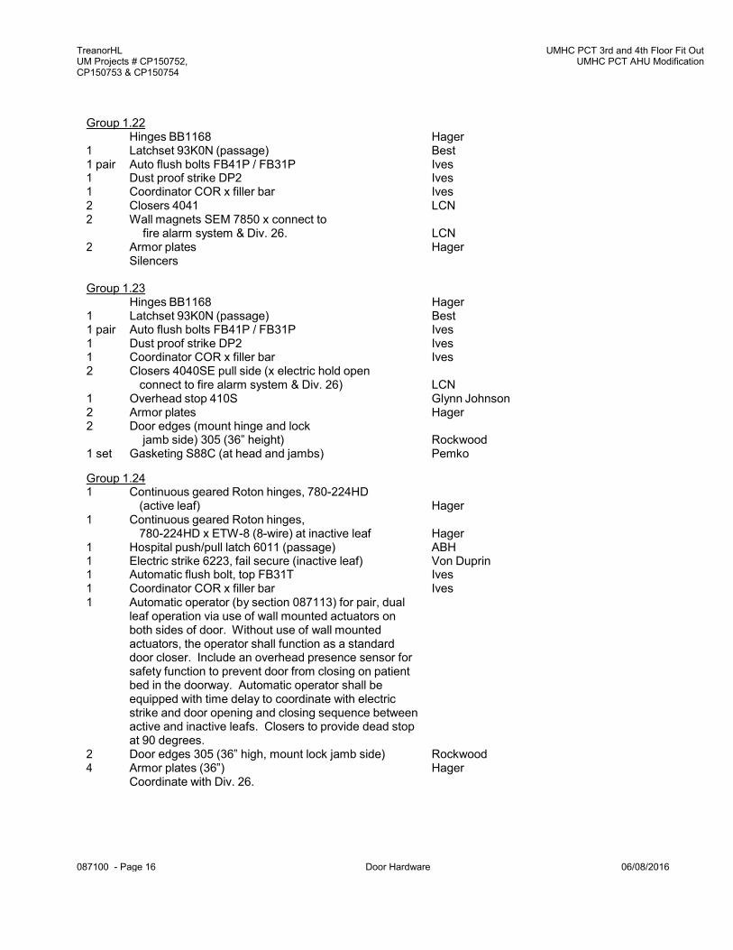
TreanorHL UM Projects # CP150752, CP150753 & CP150754
UMHC PCT 3rd and 4th Floor Fit Out UMHC PCT AHU Modification
087100 - Page 16 Door Hardware 06/08/2016
Hinges BB1168 Hager 1 Latchset 93K0N (passage) Best 1 pair Auto flush bolts FB41P / FB31P Ives 1 Dust proof strike DP2 Ives 1 Coordinator COR x filler bar Ives 2 Closers 4040SE pull side (x electric hold open
connect to fire alarm system & Div. 26) LCN 1 Overhead stop 410S Glynn Johnson 2 Armor plates Hager 2 Door edges (mount hinge and lock
jamb side) 305 (36” height) Rockwood 1 set Gasketing S88C (at head and jambs) Pemko
Group 1.22 Hinges BB1168 Hager
1 Latchset 93K0N (passage) Best 1 pair Auto flush bolts FB41P / FB31P Ives 1 Dust proof strike DP2 Ives 1 Coordinator COR x filler bar Ives 2 Closers 4041 LCN 2 Wall magnets SEM 7850 x connect to
fire alarm system & Div. 26. LCN 2 Armor plates Hager
Silencers
Group 1.23
Group 1.24 1 Continuous geared Roton hinges, 780-224HD
(active leaf) Hager 1 Continuous geared Roton hinges,
780-224HD x ETW-8 (8-wire) at inactive leaf Hager 1 Hospital push/pull latch 6011 (passage) ABH 1 Electric strike 6223, fail secure (inactive leaf) Von Duprin 1 Automatic flush bolt, top FB31T Ives 1 Coordinator COR x filler bar Ives 1 Automatic operator (by section 087113) for pair, dual
leaf operation via use of wall mounted actuators on both sides of door. Without use of wall mounted actuators, the operator shall function as a standard door closer. Include an overhead presence sensor for safety function to prevent door from closing on patient bed in the doorway. Automatic operator shall be equipped with time delay to coordinate with electric strike and door opening and closing sequence between active and inactive leafs. Closers to provide dead stop at 90 degrees.
2 Door edges 305 (36” high, mount lock jamb side) Rockwood 4 Armor plates (36”) Hager
Coordinate with Div. 26.

TreanorHL UM Projects # CP150752, CP150753 & CP150754
UMHC PCT 3rd and 4th Floor Fit Out UMHC PCT AHU Modification
087100 - Page 17 Door Hardware 06/08/2016
Group 1.25 1 Continuous geared Roton hinges, 780-224HD
(active leaf) Hager 1 Continuous geared Roton hinges,
780-224HD x ETW-8 (8-wire) at inactive leaf Hager 1 Hospital push/pull latch 6011 (passage) ABH 1 Electric strike 6223, fail secure (inactive leaf) Von Duprin 1 Automatic flush bolt, top FB31T Ives 1 Coordinator COR x filler bar Ives 1 Automatic operator (by section 087113) for pair, dual
leaf operation via use of wall plates on both sides of door. Without use of wall mounted actuators, the operator shall function as a standard door closer. Include an overhead presence sensor for safety function to prevent door from closing on patient bed in the doorway. Automatic operator shall be equipped with time delay to coordinate with electric strike and door opening and closing sequence between active and inactive leafs. Closers to provide dead stop at 90 degrees. SPECIAL NOTE: In addition, refer to operation description, below for information related to operational interlock with associated doors.
1 Power supply, model 515 (controller) Coordinate with group 1.19A and 1.26 Locknetics
2 Door edges 305 (36” high, mount lock jamb side) Rockwood 4 Armor plates (36”) Hager 1 set Gasketing S88C (at head and jambs) Pemko 1 Astragal by door manufactuer.
Status lights – Refer to electrical lighting drawings for product and installation information Coordinate with Div. 26 and electrical lighting drawings Operation Description: Door PT3220C-A – Because of air pressure requirements in this room the doors entering the Ante-Neg Pressure room are operationally interlocked to discourage multiple doors being open at the same time. If door PT3220C-A is in the open position, the door position switch signals the controller which deactivates the wall mounted actuators for the auto operator at door PT3220G-B and activates the status lights at doors PT3220G-A and PT3220G-B. Manual use of door is available, but staff will be discouraged from manually opening. The status lights are to serve as notification that the door to the OR-ISO room is open and staff would not open the other doors. Additionally, if either door PT3220G-A and PT3220G-B are open, those door position switches will deactivate the auto op wall actuator at door PT3220C-A and activate a status light inside the OR so staff would not open the door to enter until the other doors are closed and the status light is off.
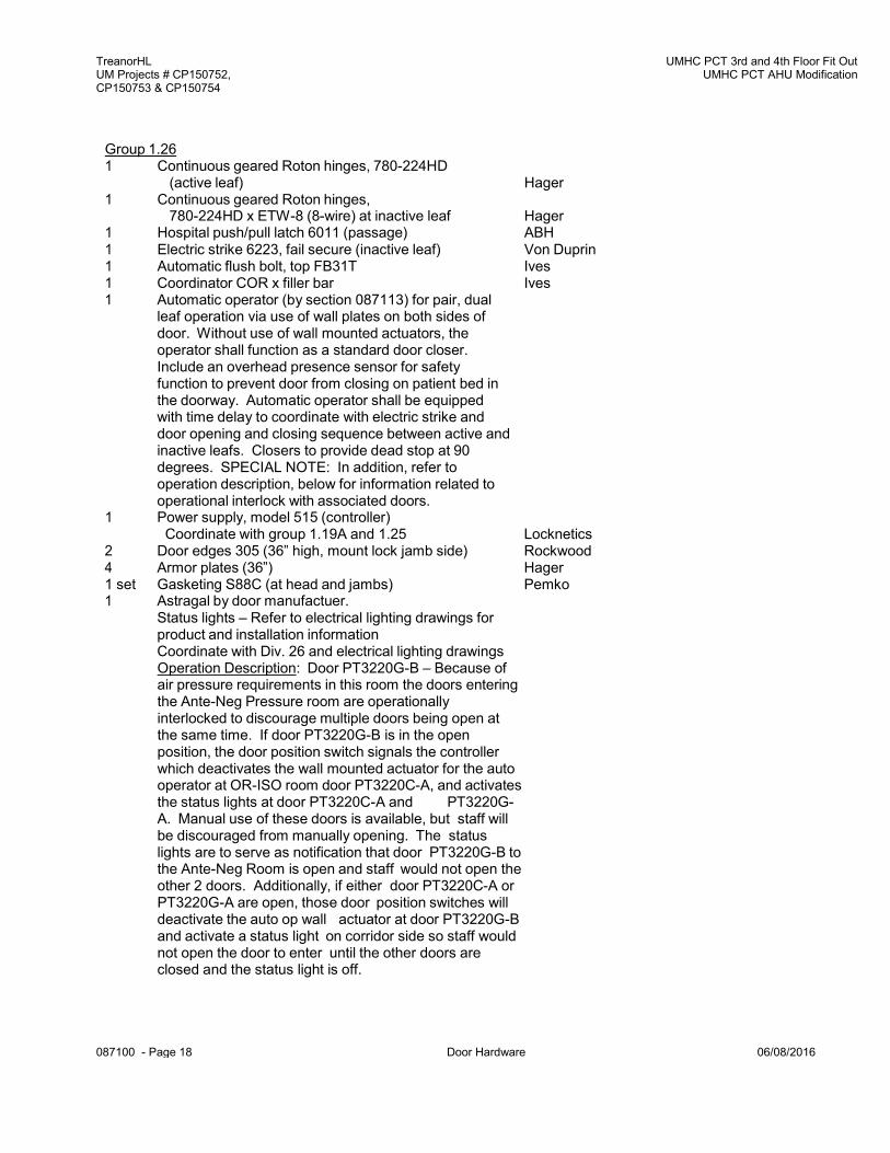
TreanorHL UM Projects # CP150752, CP150753 & CP150754
UMHC PCT 3rd and 4th Floor Fit Out UMHC PCT AHU Modification
087100 - Page 18 Door Hardware 06/08/2016
Group 1.26 1 Continuous geared Roton hinges, 780-224HD
(active leaf) Hager 1 Continuous geared Roton hinges,
780-224HD x ETW-8 (8-wire) at inactive leaf Hager 1 Hospital push/pull latch 6011 (passage) ABH 1 Electric strike 6223, fail secure (inactive leaf) Von Duprin 1 Automatic flush bolt, top FB31T Ives 1 Coordinator COR x filler bar Ives 1 Automatic operator (by section 087113) for pair, dual
leaf operation via use of wall plates on both sides of door. Without use of wall mounted actuators, the operator shall function as a standard door closer. Include an overhead presence sensor for safety function to prevent door from closing on patient bed in the doorway. Automatic operator shall be equipped with time delay to coordinate with electric strike and door opening and closing sequence between active and inactive leafs. Closers to provide dead stop at 90 degrees. SPECIAL NOTE: In addition, refer to operation description, below for information related to operational interlock with associated doors.
1 Power supply, model 515 (controller) Coordinate with group 1.19A and 1.25 Locknetics
2 Door edges 305 (36” high, mount lock jamb side) Rockwood 4 Armor plates (36”) Hager 1 set Gasketing S88C (at head and jambs) Pemko 1 Astragal by door manufactuer.
Status lights – Refer to electrical lighting drawings for product and installation information Coordinate with Div. 26 and electrical lighting drawings Operation Description: Door PT3220G-B – Because of air pressure requirements in this room the doors entering the Ante-Neg Pressure room are operationally interlocked to discourage multiple doors being open at the same time. If door PT3220G-B is in the open position, the door position switch signals the controller which deactivates the wall mounted actuator for the auto operator at OR-ISO room door PT3220C-A, and activates the status lights at door PT3220C-A and PT3220G-A. Manual use of these doors is available, but staff will be discouraged from manually opening. The status lights are to serve as notification that door PT3220G-B to the Ante-Neg Room is open and staff would not open the other 2 doors. Additionally, if either door PT3220C-A or PT3220G-A are open, those door position switches will deactivate the auto op wall actuator at door PT3220G-B and activate a status light on corridor side so staff would not open the door to enter until the other doors are closed and the status light is off.

TreanorHL UM Projects # CP150752, CP150753 & CP150754
UMHC PCT 3rd and 4th Floor Fit Out UMHC PCT AHU Modification
087100 - Page 19 Door Hardware 06/08/2016
Group 1.30 Hinges BB1279 Hager
1 Latchset 93K0N (passage) Best 1 Closer 4041 LCN 1 Kickplate Hager 1 Overhead stop, concealed, 410S Glynn Johnson 1 set Gasketing S88C at heads and jambs Pemko
Operation: The door is not locked, but is monitored and provides egress from the elevator lobby. During daytime hours, the door will not be monitored via the access control system, and card reader is not needed. After hours, the access control system will monitor the door and staff will use a card reader from either side to use the door. Use of card reader will shunt door monitoring alarm signaling an authorized access. If card reader is not used, opening the door will send a door monitoring alarm at security indicating unauthorized access.
Group 1.31
Hinges BB1279 Hager 1 Latchset, 93K0LL (hosp. privacy) Best 1 Overhead stop 410S Glynn Johnson
Silencers
Group 1.41 Hinges BB1168 Hager
1 Latchset 93K0N (passage) Best 1 Automatic flush bolt FB41T (top bolt, wood door) Ives 1 Closer 4041-18TJ plate (inactive leaf, pull side)
x special template 1630 LCN
2 Kick plates (24” height) Hager 2 Door edges (mount on hinge jamb side) Rockwood 1 Overhead stop, surface, 450F (active leaf) Glynn Johnson 1 Overhead stop, concealed 410H 410S
(hold open inactive leaf) Glynn Johnson Silencers

TreanorHL UM Projects # CP150752, CP150753 & CP150754
UMHC PCT 3rd and 4th Floor Fit Out UMHC PCT AHU Modification
087100 - Page 21 Door Hardware 06/08/2016
Hinges BB1168 Hager 1 Push plate 80S (4” x 16”) Hager 1 Pull plate 80S x 4G Hager 1 Closer 4041 LCN 1 Kickplate Hager 1 Stop Ives
Silencers
Group 1.42 Hinges BB1168 Hager
1 Latchset 93K0N (passage) Best 1 Automatic flush bolt FB41T (top bolt, wood door) Ives 1 Closer 4041 x hold open (active leaf, pull side) LCN 1 Closer 4041-18TJ plate (inactive leaf, pull side)
x special template 1630 LCN 1 Coordinator COR x filler bar Ives 2 Kick plates (24” height) Hager 2 Door edges (mount on hinge jamb side) Rockwood 1 Wall stop (active leaf) Ives 1 Overhead stop, concealed 410H 410S
(hold open inactive leaf) Glynn Johnson Silencers
Group 2.10
Group 2.14 2 Hager hinge BB1279, 4-1/2” x 4” Hager 3 Reverse Spring hinges 1257, 4-1/2” x 4” Hager 1 Magnetic catch 327 Ives 1 Pull, 8102-6 (6” ctc) x concealed wood door mounting Ives
Group 2.21 2 Continuous geared hinges, Roton 780-226HD Hager 2 Push/pull barest 159D (10” CTC) Hager 2 Closers 4041 LCN 2 Kickplates Hager 2 Stops Ives 1 set Gasketing S88C (at head and jambs) Pemko
Group 2.22 Hinges BB1168 Hager 2 Push plate 80S (4” x 16”) Hager 2 Pull plate 80S x 4G Hager 2 Closers 4041 LCN 4 Kickplates Hager 2 Stops Ives 1 set Gasketing S88C (at head and jambs) Pemko

TreanorHL UM Projects # CP150752, CP150753 & CP150754
UMHC PCT 3rd and 4th Floor Fit Out UMHC PCT AHU Modification
087100 - Page 22 Door Hardware 06/08/2016
Group 3.11 Hinges BB1168 Hager 1 Panic exit device 98L-NL-F x 996L-NL Von Duprin 1 Closer 4041 LCN 1 Kick plate Hager 1 Stop, wall Ives 1 set Gasketing S88C (at head and jambs) Pemko
Group 3.12 Hinges BB1279 Hager
1 Panic exit device 98EO-F Von Duprin 1 Closer 4041 LCN 1 Kick plate Hager 1 Stop, wall Ives 1 set Gasketing S88C (at head and jambs) Pemko
Coordinate door monitoring with Div. 26 and Security Contractor.
Group 3.15 1 Continuous geared hinge, Roton 780-224HD Hager 1 Electric power transfers EPT-10 Von Duprin 1 Panic exit device RX-EL98-NL-F x 996-NL
x MK Cyl. Von Duprin 1 Power supply PS873-AO-FA Von Duprin 1 Automatic operator by section 087113
(housing to extend across opening) Operation shall be by wall mounted actuators on both sides. Connect to fire alarm Operator shall provide dead stop at doors.
2 Kick plates Hager 1 set Gasketing S88C at head and jambs Pemko
Operation: From the card reader side, the use of card reader permits the use of the wall actuator will automatically open door. From egress side, the use of wall actuator shunts the door monitoring and electrically unlatches panic devices and then pushes the door open automatically. Doors must be Latched upon fire alarm.
Group 3.20
Hinges BB1168 Hager 1 Panic exit device 9827L-NL x 996L-NL x MK Cyl. Von Duprin 1 Panic exit device 9827EO Von Duprin 2 Closers 4041 LCN 1 Coordinator x filer bar for door width Ives 2 Kick plates Hager 1 set Gasketing S88C (at head and jambs) Pemko 2 Meeting stile gasketing 18041CNB Pemko 2 Wall stops Ives

TreanorHL UM Projects # CP150752, CP150753 & CP150754
UMHC PCT 3rd and 4th Floor Fit Out UMHC PCT AHU Modification
087100 - Page 23 Door Hardware 06/08/2016
Group 3.22 Hinges BB1168 Hager
2 Panic exit devices 9827EO-F Von Duprin 2 Closers, 4040-T-DE (slide track x double egress)
x pull side LCN 2 Wall magnets SEM 7850 x connect to
fire alarm system & Div. 26. LCN 2 Kickplates Hager 1 set Gasketing S88C (at head and jambs) Pemko
Astragal by door manufacturer Coordinate with Div. 26 Contractor. Operation: Doors are normally held in the open position and release upon fire alarm.
Group 3.23
Hinges BB1168 Hager 1 Panic exit device 9827L-NL-F x 996L-NL x MK Cyl. Von Duprin 1 Panic exit device 9827EO-F Von Duprin 2 Closers 4041 LCN 1 Coordinator x filer bar for door width Ives 2 Kick plates Hager 1 set Gasketing S88C (at head and jambs) Pemko 2 Meeting stile gasketing 18041CNB Pemko 2 Overhead stops 410S Ives
Silencers
Group 3.24A Hinges BB1168 Hager
2 Electric power transfers EPT-10 Von Duprin 1 Panic exit device RX-EL9827L-NL x LBR
x 996L-NL x MK Cyl. Von Duprin 1 Panic exit device RX-EL9827EO x LBR Von Duprin 1 Power supply PS873-2 Von Duprin 1 Coordinator x filler bar for door width Ives 2 Closers 4041 LCN 2 Kick plates Hager 2 Wall magnets SEM 7850 x connect to
access control system & Div. 26. LCN Silencers Coordinate with Div. 26 and Security Contractor. Operation: The access control system determines when the doors are to be locked or unlocked. Doors are normally held in the open position and release as determined by the access control system.

TreanorHL UM Projects # CP150752, CP150753 & CP150754
UMHC PCT 3rd and 4th Floor Fit Out UMHC PCT AHU Modification
087100 - Page 24 Door Hardware 06/08/2016
Group 3.25 Hinges BB1279 Hager
1 Panic exit device 9827L-BE x LBR x 996L-BE x MK Cyl. (passage) Von Duprin
1 Panic exit device 9827EO x LBR Von Duprin 2 Closers 4040 LCN 2 Wall magnets SEM 7850 x connect to
fire alarm system & Div. 26. LCN 2 Kickplates Hager 1 set Gasketing S88C (at head and jambs) Pemko
Coordinate with Div. 26 Contractor. Operation: Doors are normally held in the open position.
Group 3.26
Hinges BB1168 Hager 2 Electric power transfers EPT-10 Von Duprin 1 Panic exit device RX-EL9875L-NL-F x 996-NL
x MK Cyl. x 575-2 strike Von Duprin 1 Panic exit device RX-9827EO-F Von Duprin 1 Power supply PS873-2-FA Von Duprin 2 Closers 4040SE x connect to fire alarm system
& Div. 26 (mount push side) LCN 1 Coordinator x filler bar for door width x MB-F bracket Ives 2 Kick plates Hager 1 set Gasketing S88C (at head and jambs) Pemko 2 Overhead stops 410S 1 Astragal by door manufacturer.
Coordinate with Div. 26 and Security Contractor. Operation: The access control system determines when The doors are to be locked. Use of card reader will allow entrance. Doors are normally held in the open position and release upon fire alarm or access control system.
For door 1L-01N, provide the following hardware:
Group 3.22A (electric hold open)
Hinges BB1168 Hager 2 Panic exit devices 9827EO-F Von Duprin 1 Closer, 4041 x 180 degree (use w/ wall magnet) LCN 1 Wall magnet SEM 7850 x connect to
fire alarm system & Div. 26. LCN 1 Closer with electric hold open 4040SE
x connect to fire alarm system & Div. 26 mount on door without wall behind (110 deg. open) LCN
2 Kickplates Hager 1 set Gasketing S88C (at head and jambs) Pemko
Astragal by door manufacturer Coordinate with Div. 26 Contractor. Operation: Doors are normally held in the open position and release upon fire alarm.

TreanorHL UM Projects # CP150752, CP150753 & CP150754
UMHC PCT 3rd and 4th Floor Fit Out UMHC PCT AHU Modification
087100 - Page 25 Door Hardware 06/08/2016
Group 3.27 Hinges BB1168 Hager
2 Electric power transfers EPT-10 Von Duprin 1 Panic exit device RX-EL9875L-NL-F x 996-NL
x MK Cyl. x 575-2 strike Von Duprin 1 Panic exit device RX-9827EO-F Von Duprin 1 Power supply PS873-2-FA Von Duprin 1 Closers 4040SE x connect to fire alarm system
& Div. 26 (mount push side of door opening 120 deg.) LCN 1 Wall magnet SEM 7850 x connect to fire alarm system
& Div. 26. (at door with wall at 90 deg. LCN 1 Coordinator x filler bar for door width x MB-F bracket Ives 2 Kick plates Hager 1 set Gasketing S88C (at head and jambs) Pemko 2 Overhead stops 410S 1 Astragal by door manufactuer.
Coordinate with Div. 26 and Security Contractor. Operation: The access control system determines when The doors are to be locked. Use of card reader will allow entrance. Doors are normally held in the open position and release upon fire alarm or access control system.
Group 3.28
Hinges BB1168 Hager 1 Panic exit device 9827L-NL-F x 996L-NL x MK Cyl. Von Duprin 1 Panic exit device 9827EO-F Von Duprin 2 Closers 4041 LCN 1 Coordinator x filer bar for door width Ives 2 Kick plates Hager 1 set Gasketing S88C (at head and jambs) Pemko 2 Meeting stile gasketing 18041CNB Pemko 2 Stops, wall Ives
Silencers
Group 3.29 Hinges BB1168 Hager
2 Electric power transfers EPT-10 Von Duprin 1 Panic exit device RX-EL9827L-NL x 996-NL
x MK Cyl (fail secure) Von Duprin 1 Panic exit device RX-EL9827-EO (fail secure) Von Duprin 1 Power supply PS873-2 Von Duprin 2 Closers 4041 LCN 2 Kick plates Hager 1 set Gasketing S88C (at head and jambs) Pemko 2 Stops, wall Ives
Coordinate with Div. 26 and Security Contractor. Operation: The access control system determines when The doors are to be locked or unlocked. When doors are locked, the use of card reader will allow entrance.
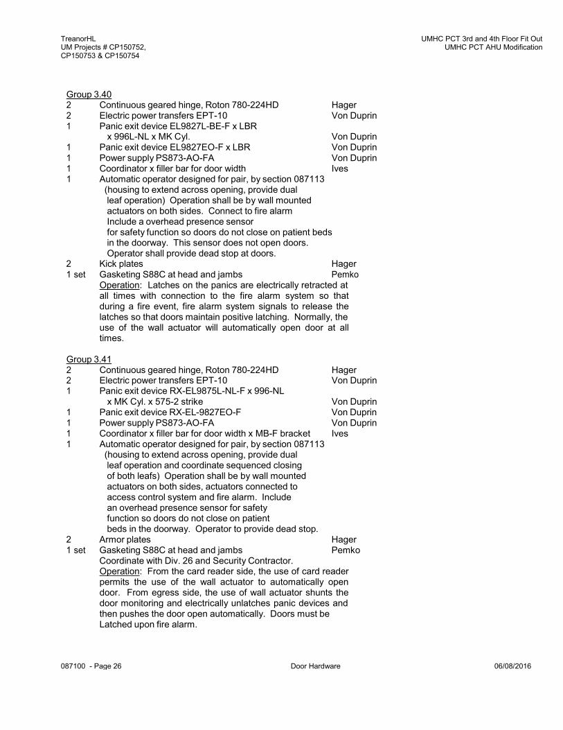
TreanorHL UM Projects # CP150752, CP150753 & CP150754
UMHC PCT 3rd and 4th Floor Fit Out UMHC PCT AHU Modification
087100 - Page 26 Door Hardware 06/08/2016
Group 3.40 2 Continuous geared hinge, Roton 780-224HD Hager 2 Electric power transfers EPT-10 Von Duprin 1 Panic exit device EL9827L-BE-F x LBR
x 996L-NL x MK Cyl. Von Duprin 1 Panic exit device EL9827EO-F x LBR Von Duprin 1 Power supply PS873-AO-FA Von Duprin 1 Coordinator x filler bar for door width Ives 1 Automatic operator designed for pair, by section 087113
(housing to extend across opening, provide dual leaf operation) Operation shall be by wall mounted actuators on both sides. Connect to fire alarm Include a overhead presence sensor for safety function so doors do not close on patient beds in the doorway. This sensor does not open doors. Operator shall provide dead stop at doors.
2 Kick plates Hager 1 set Gasketing S88C at head and jambs Pemko
Operation: Latches on the panics are electrically retracted at all times with connection to the fire alarm system so that during a fire event, fire alarm system signals to release the latches so that doors maintain positive latching. Normally, the use of the wall actuator will automatically open door at all times.
Group 3.41 2 Continuous geared hinge, Roton 780-224HD Hager 2 Electric power transfers EPT-10 Von Duprin 1 Panic exit device RX-EL9875L-NL-F x 996-NL
x MK Cyl. x 575-2 strike Von Duprin 1 Panic exit device RX-EL-9827EO-F Von Duprin 1 Power supply PS873-AO-FA Von Duprin 1 Coordinator x filler bar for door width x MB-F bracket Ives 1 Automatic operator designed for pair, by section 087113
(housing to extend across opening, provide dual leaf operation and coordinate sequenced closing of both leafs) Operation shall be by wall mounted actuators on both sides, actuators connected to access control system and fire alarm. Include an overhead presence sensor for safety function so doors do not close on patient beds in the doorway. Operator to provide dead stop.
2 Armor plates Hager 1 set Gasketing S88C at head and jambs Pemko
Coordinate with Div. 26 and Security Contractor. Operation: From the card reader side, the use of card reader permits the use of the wall actuator to automatically open door. From egress side, the use of wall actuator shunts the door monitoring and electrically unlatches panic devices and then pushes the door open automatically. Doors must be Latched upon fire alarm.

TreanorHL UM Projects # CP150752, CP150753 & CP150754
UMHC PCT 3rd and 4th Floor Fit Out UMHC PCT AHU Modification
087100 - Page 27 Door Hardware 06/08/2016
Group 3.42 2 Continuous geared hinge, Roton 780-224HD Hager 2 Electric power transfers EPT-10 Von Duprin 1 Panic exit device RX-EL9827L-NL x LBR
x 996L-NL x MK Cyl. Von Duprin 1 Panic exit device RX-EL9827EO x LBR Von Duprin 1 Power supply PS873-2-AO-FA Von Duprin 1 Coordinator x filler bar for door width Ives 1 Automatic operator designed for pair, by section 087113
(housing to extend across opening, provide dual leaf operation and coordinate sequenced closing of both leafs) Operation shall be by wall actuators on both sides, connected to access control system. Include an overhead presence sensor for safety function so doors do not close on patient beds in the doorway. Operator to provide dead stop.
2 Armor plates Hager 1 set Gasketing S88C at head and jambs Pemko
Coordinate with Div. 26, and Security Contractor. Operation: From the card reader side, the use of card reader permits the use of the wall actuator to automatically open door. From egress side, the use of wall actuator shunts the door monitoring and electrically unlatches panic devices and then pushes the door open automatically. Doors can also be unlocked via remote release at nurse station PT8271.
Group 4.00
All hardware by door manufacturer.
Group 4.01 All hardware by door manufacturer except for:
1 masterkeyed cylinder (where required) Best
Group 4.10 Hinges BB1168 Hager
1 Latchset 93K0N (passage) Best 1 Closer 4041 LCN 1 Overhead stop 410S Glynn Johnson 1 set Weather-stripping at head and jambs provided by
door & frame manufacturer
Group 4.11 Hinges BB1168 Hager
1 Latchset 93K0N (passage) Best 1 Closer 4041 LCN 1 Overhead stop 410H Glynn Johnson 1 set Weather-stripping at head and jambs provided by
door & frame manufacturer

TreanorHL UM Projects # CP150752, CP150753 & CP150754
UMHC PCT 3rd and 4th Floor Fit Out UMHC PCT AHU Modification
087100 - Page 28 Door Hardware 06/08/2016
Group 4.12 Hinges BB1279 Hager
1 Lockset 93K7R (classroom) Best 1 Closer 4041 LCN 1 Overhead stop 410S Glynn Johnson 1 set Weather-stripping at head and jambs provided by
door & frame manufacturer
Group 4.13 1 Continuous geared hinge, Roton 780-226HD
(finish to match door and frame) Hager 1 Push/pull barset 9190 x 10” ctc pull, NO mounting Ives 1 Automatic Operator by section 087113
Operation via wall mounted actuators on both sides when electric strike is released. Coordinate with Security Contractor. Provide relay to coordinate release of electric strike and opening of door. Operator to provide dead stop.
1 Threshold 272 Pemko 1 set Weather-stripping at head and jambs provided by
door manufacturer
Group 4.14 1 Continuous geared hinge, Roton 780-226HD
(finish to match door and frame) Hager 1 Lockset 93K7R (classroom) Best 1 Closer 4041 LCN 1 Overhead stop 410H (hold open) Glynn Johnson 1 set Weather-stripping at head and jambs provided by
door & frame manufacturer
Group 4.21 Hinges BB1168 Hager
1 Lockset 93K7R (classroom) Best 1 pair Auto flush bolts FB31P Ives 1 Dust proof strike DP2 Ives 1 Coordinator COR x filler bar Ives 2 Closers 4041 LCN 2 Floor stops (@ 180 degree open) Ives 1 set Weather-stripping at head and jambs provided by
door & frame manufacturer
Group 5.10 Hinges BB1279 Hager 1 Lockset 93K7A (office) Best 1 Stop Ives
Silencers

TreanorHL UM Projects # CP150752, CP150753 & CP150754
UMHC PCT 3rd and 4th Floor Fit Out UMHC PCT AHU Modification
087100 - Page 29 Door Hardware 06/08/2016
Group 5.11 Hinges BB1279 Hager 1 Lockset 93K7A (office) Best 1 Closer 4041 LCN 1 Kickplate Hager 1 Stop Ives 1 set Gasketing S88C at heads and jambs Pemko
Group 5.13 Hinges BB1279 Hager 1 Lockset 93K7A (office) Best 1 Closer 4041 LCN 1 Kickplate Hager 1 Overhead stop 410S Glynn Johnson 1 set Gasketing S88C at heads and jambs Pemko
Group 7.10 Hinges BB1279 Hager 1 Lockset 93K7R (classroom) Best 1 Stop Ives
Silencers
Group 7.11 Hinges BB1279 Hager 1 Lockset 93K7R (classroom) Best 1 Closer 4041 LCN 1 Kickplate Hager 1 Stop Ives 1 set Gasketing S88C at heads and jambs Pemko
Group 7.12 Hinges BB1279 Hager 1 Lockset 93K7R (classroom) Best 1 Closer 4041 LCN 1 Kickplate Hager 1 Overhead stop 410S Glynn Johnson 1 set Gasketing S88C at heads and jambs Pemko
Group 7.13 Hinges BB1279 Hager 1 Lockset 93K7R (classroom) Best 1 Closer 4041 LCN 1 Kickplate Hager 1 Overhead stop 410S Glynn Johnson
Silencers
Group 7.14 Hinges BB1279 Hager 1 Lockset 93K7R (classroom) Best 1 Closer 4041 LCN 1 Kickplate Hager 1 Stop Ives
Silencers

TreanorHL UM Projects # CP150752, CP150753 & CP150754
UMHC PCT 3rd and 4th Floor Fit Out UMHC PCT AHU Modification
087100 - Page 30 Door Hardware 06/08/2016
Group 7.22 Hinges BB1168 Hager 1 Lockset 93K7R (classroom) Best 1 pair Auto flush bolts FB41P / FB31P Ives 1 Dust proof strike DP2 Ives 1 Coordinator COR x filler bar Ives 2 Closers 4041 LCN 2 Kick plates Hager 2 Wall stops Ives 1 set Gasketing S88C (at head and jambs) Pemko
Group 7.23 Hinges BB1279 Hager 1 Lockset 93K7R (classroom) Best 1 pair Auto flush bolts FB41P / FB31P Ives 1 Dust proof strike DP2 Ives 1 Coordinator COR x filler bar Ives 2 Closers 4041 LCN 2 Kick plates Hager 2 Overhead stops 410H (hold open) Glynn Johnson
Silencers
Group 7,24 Hinges BB1279 Hager
1 Lockset 93K7R (classroom) Best 1 Automatic flush bolt FB31T/FB41T (top bolt) Ives 1 Closer 4011-H (hold open arm
at small, inactive leaf, mount pull side x special template ST3579 LCN
2 Kick plates (corridor side) Hager 2 Door edges 305 (mount hinge jamb side) Rockwood 1 Overhead stop, surface, 906S at large, active leaf Glynn Johnson 1 Overhead stop, surface, 451S at inactive leaf
x engineered special for use on an 18” leaf (short slider x 451 special template to allow door to open 91 degree to clear mounting with flush bolt.) Mount push side. Glynn Johnson
Silencers
Group 7,25 Hinges BB1168 Hager
1 Lockset 93K7R (classroom) Best 1 Automatic flush bolt FB31T/FB41T (top bolt) Ives 1 Closer 4111 (mount push side of inactive leaf) x
Special template ST2730 (with 62G shoe) LCN 2 Armor plates (corridor side) Hager 2 Door edges 305 (mount hinge jamb side) Rockwood 1 Overhead stop, surface, 906S at large, active leaf Glynn Johnson 1 Overhead stop, surface, 902H (hold open) at inactive
leaf, mount push side. Glynn Johnson Silencers

TreanorHL UM Projects # CP150752, CP150753 & CP150754
UMHC PCT 3rd and 4th Floor Fit Out UMHC PCT AHU Modification
087100 - Page 31 Door Hardware
Group 8.11 Hinges BB1279 Hager 1 Lockset 93K7D (storeroom) Best 1 Closer 4041 LCN 1 Kickplate Hager 1 Stop Ives
Silencers
Group 8.12 Hinges BB1279 Hager 1 Lockset 93K7D (storeroom) Best 1 Closer 4041 LCN 1 Kickplate Hager 1 Overhead stop 410S Glynn Johnson
Silencers
Group 8.13 Hinges BB1279 Hager 1 Lockset 93K7D (storeroom) Best 1 Closer 4041 LCN 1 Kickplate Hager 1 Overhead stop 410S Glynn Johnson 1 set Gasketing S88C at heads and jambs Pemko
Group 8.14 Hinges BB1279 Hager 1 Lockset 93K7D (storeroom) Best 1 Closer 4041 LCN 1 Kickplate Hager 1 Stop Ives 1 set Gasketing S88C at heads and jambs Pemko
Group 8.15 Hinges BB1279 Hager 1 Electric through wire hinge BB1279 x ETW-8 Hager 1 Lockset, electrified with request to exit,
93KW7DEU x RQE (fail secure) x TCM (temp. control module) Best 1 Closer 4041 LCN 1 Kickplate Hager 1 Wall stop Ives
Silencers Coordinate with Div. 26 and Security Contractor.

TreanorHL UM Projects # CP150752, CP150753 & CP150754
UMHC PCT 3rd and 4th Floor Fit Out UMHC PCT AHU Modification
087100 - Page 32 Door Hardware
Group 8.15A Hinges BB1279 Hager 1 Electric through wire hinge BB1279 x ETW-8 Hager 1 Lockset, electrified with request to exit,
93KW7DEU x RQE (fail secure) x TCM (temp. control module) Best 1 Closer 4041 LCN 1 Kickplate Hager 1 Overhead stop 410S Glynn Johnson
Silencers Coordinate with Div. 26 and Security Contractor.
Group 8.15B Hinges BB1279 Hager 1 Electric through wire hinge BB1279 x ETW-8 Hager 1 Lockset, electrified with request to exit,
93KW7DEU x RQE (fail secure) x TCM (temp. control module) Best 1 Closer 4041 LCN 1 Kickplate Hager 1 Wall stop Ives 1 set Gasketing S88C (at head & jambs) Pemko
Coordinate with Div. 26 and Security Contractor.
Group 8.15C Hinges BB1279 Hager 1 Electric through wire hinge BB1279 x ETW-8 Hager 1 Lockset, electrified with request to exit,
93KW7DEU x RQE (fail secure) x TCM (temp. control module) Best 1 Closer 4041 LCN 1 Kickplate Hager 1 Overhead stop 410S Glynn Johnson 1 set Gasketing S88C (at head & jambs) Pemko
Coordinate with Div. 26 and Security Contractor.
Group 8.15D Hinges BB1279 Hager 1 Electric through wire hinge BB1279 x ETW-8 Hager 1 Lockset, electrified with request to exit,
93KW7DEU x RQE (fail secure) x TCM (temp. control module) Best 1 Closer 4041 LCN 1 Kickplate Hager 1 Wall stop Ives 1 set Gasketing S88C (at head & jambs) Pemko 1 Auto door bottom 434CRL Pemko
Coordinate with Div. 26 and Security Contractor.

TreanorHL UM Projects # CP150752, CP150753 & CP150754
UMHC PCT 3rd and 4th Floor Fit Out UMHC PCT AHU Modification
087100 - Page 33 Door Hardware
Group 8.16 Hinges BB1168 Hager
1 Electric through wire hinge BB1168 x ETW-8 Hager 1 Lockset, electrified with request to exit,
93KW7DEL x RQE (fail safe) x TCM (temp. control module) Best
1 Closer 4041 LCN 1 Kickplate Hager 1 Overhead stop 410S Glynn Johnson 1 set Gasketing S88C (at head & jambs) Pemko
Coordinate with Div. 26, Fire Alarm, and Security Contractor
Group 8.17
Hinges BB1279 Hager 1 Electric through wire hinge BB1279 x ETW-8 Hager 1 Lockset, electrified with request to exit,
93KW7DEU x RQE (fail secure) x TCM (temp. control module) Best
1 Closer 4041 LCN 1 Kickplate Hager 1 Overhead stop 410S Glynn Johnson 1 set Gasketing S88C (at head & jambs) Pemko
Coordinate door monitoring and locking/unlocking of door with Div. 26 and Security Contractor.
Group 8.23
Hinges BB1279 Hager 1 Lockset 93K7D (storeroom) Best 1 pair Auto flush bolts FB41P / FB31P Ives 1 Dust proof strike DP2 Ives 1 Coordinator COR x filler bar Ives 2 Closers 4041 LCN 2 Kick plates Hager 2 Wall stops Ives
Silencers
Group 8.24 Hinges BB1279 Hager 1 Lockset 93K7D (storeroom) Best 1 pair Auto flush bolts FB41P / FB31P Ives 1 Dust proof strike DP2 Ives 1 Coordinator COR x filler bar Ives 2 Closers 4041 LCN 2 Kick plates Hager 2 Overhead stops 410S Glynn Johnson 1 set Gasketing S88C (at head and jambs) Pemko

TreanorHL UM Projects # CP150752, CP150753 & CP150754
UMHC PCT 3rd and 4th Floor Fit Out UMHC PCT AHU Modification
087100 - Page 34 Door Hardware
Group 8.25 Hinges BB1279 Hager
1 Electric through wire hinge BB1279 x ETW-8 Hager 1 Lockset, electrified with request to exit,
93KW7DEU x RQE (fail secure) x TCM (temp. control module) Best
1 pair Auto flush bolts FB41P / FB31P Ives 1 Dust proof strike DP2 Ives 1 Coordinator COR x filler bar Ives 2 Closers 4041 LCN 2 Kickplates Hager 2 Wall stops Ives
Silencers Coordinate card reader with Div. 26 and Security Contractor.
Group 8.26 2 Continuous geared hinges, Roton 780-224HD Hager 2 Electric power transfer EPT-10 Von Duprin 1 Lockset, electrified with request to exit,
93KW7DEU x RQE (fail secure) x TCM (temp. control module) Best
1 Electric strike 6223, fail secure Von Duprin 1 pair Auto flush bolts FB41P / FB31P Ives 1 Dust proof strike DP2 Ives 1 Coordinator COR x filler bar Ives 1 Automatic operator designed for pair, by section 087113
(housing to extend across opening, provide dual leaf operation) Operation shall be by wall mounted actuators coordinated with card reader. Operator shall provide dead stop at doors. Provide safety sensor for patient beds in doorway.
2 Kickplates Hager 4 Door edge guards, mounted at hinge
and jamb sides 305 Rockwood Coordinate card reader with Div. 26 and Security Contractor. Operation: Use of card reader activates electric lock and allows entry with or without auto operator. Automatic operator will be activated by wall mounted actuator on either side of door. When the door is locked by access control, the entry side wall actuator shall not operate. The interior wall actuator is always active. From corridor side, use of card reader and then use of wall actuator releases electric strike and automatic operator opens the doors. Automatic operator shall be equipped with time delay to coordinate with elec. strike, auto flush bolts and shall coordinate the proper closing sequence of both doors.

TreanorHL UM Projects # CP150752, CP150753 & CP150754
UMHC PCT 3rd and 4th Floor Fit Out UMHC PCT AHU Modification
087100 - Page 35 Door Hardware
Group 8.27 2 Continuous geared hinges, Roton 780-224HD Hager 2 Electric power transfer EPT-10 Von Duprin 1 Lockset, electrified with request to exit,
93KW7DEU x RQE (fail secure) x TCM (temp. control module) Best
1 Electric strike 6223, fail secure Von Duprin 1 pair Auto flush bolts FB41P / FB31P Ives 1 Dust proof strike DP2 Ives 1 Coordinator COR x filler bar Ives 1 Automatic operator designed for pair, by section 087113
(housing to extend across opening, provide dual leaf operation) Operation shall be by wall actuators on inside and by card reader on outside. Operator shall provide dead stop at doors. Provide safety sensor for patient beds in doorway.
2 Kickplates Hager 1 set Gasketing S88C (at head and jambs) Pemko 4 Door edge guards, mounted at jambs 305 Rockwood
Coordinate card reader with Div. 26 and Security Contractor. Operation: Use of card reader activates electric lock and allows entry with or without auto operator. Automatic operator will be activated by wall mounted actuators on either side of door. When the door is locked by access control, the entry side wall actuator shall not operate. The interior wall actuator is always active. From corridor side, use of card reader and wall actuator releases electric strike and automatic operator opens the doors. Automatic operator shall be equipped with time delay to coordinate with elec. strike, auto flush bolts and shall coordinate the proper closing sequence of both doors.
Group 8.28
Hinges BB1279 Hager 1 Electric through wire hinge BB1279 x ETW-8 Hager 1 Lockset, electrified with request to exit,
93KW7DEU x RQE (fail secure) x TCM (temp. control module) Best 1 Automatic flush bolt FB41T (top bolt, wood door) Ives 1 Coordinator COR x filler bar Ives 1 Closer 4011 (active leaf) LCN 1 Closer 4011 (at small, inactive leaf, mount pull side
x special template ST3579 LCN 2 Kick plates (corridor side) Hager 1 Overhead stop, surface, 450S at large, active leaf Glynn Johnson 1 Overhead stop, surface, 451S at inactive leaf
x engineered special for use on an 18” leaf (short slider x 451 special template to allow door to open 91 degree to clear mounting with flush bolt.) Mount push side. Glynn Johnson 1 set Gasketing S88C (at head and jambs) Pemko

TreanorHL UM Projects # CP150752, CP150753 & CP150754
UMHC PCT 3rd and 4th Floor Fit Out UMHC PCT AHU Modification
087100 - Page 36 Door Hardware
Group 8.40 Hinges BB1168 Hager
1 Lockset 93K7D (storeroom) Best 1 Automatic flush bolt FB41T (top bolt, wood door) Ives 1 Closer 4041 x hold open (active leaf, pull side) LCN 1 Closer 4041-18TJ plate (inactive leaf, pull side)
x special template 1630 LCN 1 Coordinator COR x filler bar Ives 2 Kick plates (24” height) Hager 2 Door edges (mount hinge jamb side) Rockwood 1 Wall stop (active leaf) Ives 1 Overhead stop, concealed 410H 410S
(hold open inactive leaf) Glynn Johnson Silencers
Group 9.11
1 set Pivots L117 x Intermediate pivot ML19 (lead lined) Coordinate beveled door edge Rixson
1 Lockset 93K7R-LL (classroom) x lead lining Best 1 Overhead stop 410S (x lead lined fasteners) Glynn Johnson
Group 9.15
1 set 1
Pivots L117 x Intermediate pivot ML19 (lead lined) Coordinate beveled door edge
Electrified pivot EML19 x special layout 1610
Rixson Rixson
1 Lockset, electrified with request to exit, 93KW7DEU-LL x RQE (lead lined) (fail secure) x TCM (temp. control module) Best 1 Closer 4041 (mount pull side) (x lead lined fasteners) LCN 1 Kickplate (adhesive applied) Hager 1 Wall stop Ives
Silencers Coordinate with Div. 26 and Security Contractor.
Group
2 sets Pivots L117 x Intermediate pivot ML19
Coordinate beveled door edge Rixson 1 Lockset 93K7R-LL (classroom) x lead lining Best 1 Closer 4041 x hold open (mount top jamb, push
side, active leaf) x lead lined fasteners LCN 1 Closer 4030 x H-Spring CUSH, hold open (top jamb
push side, inactive leaf) (x lead lined fasteners) LCN 1 Coordinator COR x filler bar x lead lined fasteners Ives 1 pair Automatic flush bolts FB41P (wood) Ives 1 Dust proof strike DP2 Ives 2 Kickplates (adhesive applied) Hager 1 Wall stop (active leaf) Ives
Silencers Lead lined astragal by door manufacturer.
END OF SECTION 087100

THIS PAGE INTENTIONALLY LEFT BLANK

TreanorHL UM Projects # CP150752, CP150753 & CP150754
UMHC PCT 3rd and 4th Floor Fit Out UMHC PCT AHU Modification
087113 - Page 1 Automatic Door Operators
SECTION 087113 - AUTOMATIC DOOR OPERATORS PART 1 - GENERAL
1.1 RELATED DOCUMENTS
A. Drawings and general provisions of the Contract, including General and
Supplementary Conditions and Division 1 Specification Sections apply to this Section.
1.2 SUMMARY
A. This Section includes the following types of door operators:
1. Power units for swing doors.
B. Related Sections: The following Sections contain requirements that relate to this
Section:
1. Electrical connections are specified in Division 26. 1.3 SUBMITTALS
A. Product data for each door operator type required, including the manufacturer's
standard details and fabrication methods and general published recommendations for each component of the door operating systems required, and the following:
1. Roughing-in diagrams.
2. Certified performance reports.
3. Installation instructions.
4. Parts lists.
B. Wiring diagrams detailing wiring for power operator, signal, and control systems. Clearly
differentiate between manufacturer-installed wiring and field-installed wiring.
C. Maintenance Data: Submit manufacturer's maintenance and service data for door operators and control system including the name, address and telephone number of the nearest authorized service representative.
1.4 QUALITY ASSURANCE
A. Installer Qualifications: Engage an experienced Installer who is an authorized representative of the manufacturer for the installation and maintenance of the type of units required for this Project.
B. Manufacturer's Qualifications: Provide door operators produced by a firm experienced in
manufacturing operators that are similar to those indicated for this Project and that have a record of successful in-service performance.
C. Fire-Rated and Emergency Exit Openings: Provide door operators that comply with
NFPA 80 requirements for doors as emergency exits, and do not interfere with fire

TreanorHL UM Projects # CP150752, CP150753 & CP150754
UMHC PCT 3rd and 4th Floor Fit Out UMHC PCT AHU Modification
087113 - Page 2 Automatic Door Operators
ratings.
D. BHMA Standard: Provide power door operators that comply with applicable requirements of ANSI A156.19 2002 Power Assist and Low Energy Power Operated Doors, Power Operated Pedestrian Door Standard.
E. UL Standard: Provide power door operators that comply with UL 325.
1.5 WARRANTY
A. Warranty: Submit a written warranty, executed by the manufacturer, agreeing to repair or
replace components of the power door operator system that fail in materials or workmanship within the specified warranty period. Failures include, but are not necessarily limited to:
1. Faulty operation of operators and controls.
2. Deterioration of metals, metal finishes, and other materials beyond normal
weathering.
B. Warranty Period: 3 years after the date of Substantial Completion.
C. The warranty shall not deprive the Owner of other rights or remedies that the Owner may have under other provisions of the Contract Documents and is in addition to, and runs concurrent with, other warranties made by the Contractor under requirements of the Contract Documents.
PART 2 - PRODUCTS
2.1 GENERAL DOOR OPERATOR REQUIREMENTS
A. Capacity: Provide operators of the size recommended by the manufacturer for the door size, weight, and movement, for condition of exposure, and for long-term, maintenance- free operation under normal traffic load for the type of occupancy indicated.
B. Hinge Operation: For swing type doors, refer to Division 8 Section "Finish Hardware" to
determine type of hinge action to be matched by the door operator action.
C. Exposed Housing: Minimum 0.062-inch-thick extruded or formed aluminum cover with provisions for maintenance access. Provide fasteners that are concealed when door is in the closed position. Finish to match doors and frames.
D. Adjustment Features: Operators shall be fully adjustable. Provide adjustment for
opening, closing, and checking speeds, as well as length of time the door remains open. 2.3 SWINGING DOOR OPERATORS
A. Basis-of-Design And Preferred Door Operator: Provide Magic Force by Stanley,
or comparable product by one of the following:
4100LE by Horton Or Approved by LCN or BESAM
B. Exposed Housing for Operators: Aluminum with provisions for maintenance access.
Provide fasteners that are concealed when door is in the closed position. Finish to match frames. Housing to extended across head of both doors when in pairs.
C. Electro-Mechanical Operator for Swinging Doors: Provide the manufacturer's standard
TreanorHL UM Projects # CP150752, CP150753 & CP150754
UMHC PCT 3rd and 4th Floor Fit Out UMHC PCT AHU Modification
087113 - Page 3 Automatic Door Operators
electro-mechanical unit with doors power-opened and spring-closed, with the closing speed controlled mechanically by gear train and dynamically by braking action of electric motor and, with easy manual operation including spring closing with power off. Provide operator action as indicated and mounting as indicated below:
1. Operator Mounting Type: Surface-mounted overhead operator.
2. Power Assisted Doors: Power assist operator shall comply with ANSI A156.19-
2002.
3. Fire Door Accessories: Provide fire door accessory package consisting of UL- listed latch mechanism power reset box, and caution labels for fire-resistance rated doors indicated for electro-mechanical operation.
2.4 OPERATOR CONTROL SYSTEMS
A. Touchless Switch: BEA, Inc.”MS-08” microwave sensor that operates at 24.125
GHz (K-band frequency). Sensor shall have an adjustable range of 2 inches (51 mm) to 24 inches (609 mm). Sensor shall be concealed behind a black polycarbonate faceplate with white lettering that states “WAVE TO OPEN” as well as a logo of a hand. Wireless push plates are not acceptable.
1. Operation: Where doors are operated by means of touchless switch, provide
switches on both side of each door equipped with door operator. The activation of the door by the manual action feature shall be deactivated.
B. Units shall be set for low energy operation.
C. Presence Detection System: Provide an overhead presence sensor system for safety function. System requiring exposed wire loops shall not be permitted.
PART 3 - EXECUTION
3.1 PREPARATION
A. Templates and Diagrams: Furnish templates, diagrams, and other data to fabricators
and installers of related work, as necessary, for coordination of the power door operator installation.
3.2 INSTALLATION
A. General: Comply with manufacturer's recommendations.
B. Install complete power door operator system in accordance with manufacturer's
instructions, including controls, control wiring, and remote power units.
Refer to Division 26Sections for power connection specifications.
C. Set header assemblies, operating brackets, rails, and guides level and true to location with adequate anchorage for permanent support.
3.3 ADJUSTING
A. After repeated operation of completed installation equivalent to 3 days use by normal
traffic (100 to 300 cycles), readjust door operators and controls for optimum operating condition and safety. Lubricate hardware, operating equipment, and other moving parts.
END OF SECTION 087113

012100 - Page 1
INTERIOR GLAZING
TreanorHL UM Projects # CP150752, CP150753 & CP150754
UMHC PCT 3rd and 4th Floor Fit Out UMHC PCT AHU Modification
SECTION 088005 - INTERIOR GLAZING
PART 1 - GENERAL
1.1 RELATED DOCUMENTS
A. Drawings and general provisions of the Contract, including General and
Supplementary Conditions and Division 01 Specification Sections, apply to this Section.
1.2 SUMMARY
A. Definitions: "Glass" includes prime glass, processed glass, and fabricated glass
products. "Glazing" includes glass installation and materials used to install glass. Types of work in this section include glass and glazing for:
1. ½” Clear Tempered Glass with integral image (GLF-14)
2. Standard Interior glass.
3. Glass with integral blinds.
4. Fire rated glass.
1.3 QUALITY ASSURANCE:
A. Prime Glass Standard: ASTM C 1036.
B. Heat-Treated Glass Standard: ASTM C 1048.
C. Distortion: In order to minimize distortion in glass units, tempering shall be done
by the horizontal process, and the bow and warpage shall not exceed 0.003".
1.4 SUBMITTALS:
A. Samples: 2 samples, 12" square, of each glass product, except for clear single-pane units.
B. Product Data: For each glass product and glazing material indicated.
1.5 JOB CONDITIONS:
A. Pre-Installation Meeting: Meet with Glazier and other trades affected by glass installation, prior to beginning of installation. Do not perform work under adverse weather or job conditions. Install liquid sealants when temperatures are within lower or middle third of temperature range recommended by manufacturer.
1.6 WARRANTY:
A. Fire Rated Glass:
012100 - Page 2
INTERIOR GLAZING
TreanorHL UM Projects # CP150752, CP150753 & CP150754
UMHC PCT 3rd and 4th Floor Fit Out UMHC PCT AHU Modification
1. Provide manufacturer's limited warranty for the following period:.
a. Warranty period: Five years from date of shipment by manufacturer.
B. Glass With Integral Blinds:
1. Vision Control Glass in Interior Locations: Furnish manufacturer’s 10-
year warranty providing coverage against material obstruction of glass units by dust or film formation due to failure of hermetic seal.
C. ½” Clear Tempered Glass with integral image: Provide manufacturer’s standard
warranty. PART 2 - PRODUCTS
2.1 GLASS PRODUCTS:
A. General: Glass shall have the edges, not concealed by stops, channels or trim,
ground and polished with a light polished seam on both surfaces. On tempered glass, edge polishing shall be completed prior to tempering.
B. Clear Float Glass (CL-18).: ASTM C 1036, Type I, Quality q3, Class 1.
2.2 PROCESSED GLASS:
A. Heat-Treated Glass: ASTM C 1048; Type I, Quality q3, as specified.
1. Tempered Glass.: Provide prime glass of color and type specified or
indicated, which has been fully tempered to strengthen glass in bending to not less than 4.5 times annealed strength. Provide tempered glass where used in conjunction with doors and sidelights; and for a fixed or operable panel when the glazing meetings the following conditions:
a. when an individual pane is greater than 9 square feet b. and where the bottom edge of glass is less than 18" above finished
floor, c. and when walking surfaces are within 36" of glass plane d. and when glazing is within 4’-0" of door e. Insulated units occurring in the above locations shall have both
lites are tempered.
2. Heat-Strengthened Glass: Provide prime glass of color and type indicated, which has been heat treated to strengthen glass in bending to not less than 2.0 times annealed strength.
2.3 GLASS UNITS WITH INTEGRAL BLINDS:
A. Product/Manufacturer: "Vision Control" by Unicel Architectural, Inc., Boucherville,
Province of Quebec, Canada, or approved equal.
B. Blinds: The 1 3/8" louvers shall be made of extruded aluminum, hollow-chambered profile with overlap, alloy 6063 T-5. The louvers shall be secured at
012100 - Page 3
INTERIOR GLAZING
TreanorHL UM Projects # CP150752, CP150753 & CP150754
UMHC PCT 3rd and 4th Floor Fit Out UMHC PCT AHU Modification
both ends with molded pivots and shall operate without cords or strings. The louvers shall be mounted horizontally. Color: As selected by the Architect.
C. All pivots, pinions, and racks shall be made of UV stabilized materials to ensure
dimensional stability, durability, and maintenance-free service never needing lubrication.
D. Operation: The rotation of the blades shall be controlled through a thumb knob.
The blades shall rotate 180 degrees in a continuous cycle. The axle of the mechanism shall be on the left or right side and on one or both sides as indicated or as directed by the Architect.
E. Glass Types: Provide tempered glass as specified, scheduled and indicated.
2.4 LAMINATED GLASS:
A. Glass: Fabricate clear laminated glass from Mo (2) layers of clear glass,
laminated together with not less than 0.030" thick plastic interlayer, using Iaminator's standard heat- plus-pressure process to produce glass free from foreign substances and air/gas pockets. Thickness: 1/2"
2.5 FIRE-RATED GLASS:
A. Fire-Rated Glass: Provide "FireLite Plus" as manufactured by the Pilkington
Group and distributed by Technical Glass Products, Kirkland, Washington, or approved equal
2.6 CLEAR TEMPERED GLASS WITH INTEGRAL IMAGE A. General: Provide ½” clear tempered glass with integral image (GLF-14) for
Glazing two of the three panels of the ICU / CCU Sliders for the Perioperative Rooms.
B. Install per door manufactures instructions. C. Sole Source:
1. Skyline Design 888.278.4660 www.skydesign.com 2. Reference: Project / Quote: MUHC Patient Tower / #96543 3. Control Sample #: #98647-002 GLF 14 4. Product Data: Organics – Branches – Design consists of Custom Scale
partial-height Branches pattern – a two-sided etched pattern per layout shown on www.skydesign.com
2.7 GLAZING SEALANTS AND COMPOUNDS:
A. General: Provide light gray color of exposed sealant/compound as approved by Architect. Comply with manufacturer's recommendations for selection of hardness, depending upon the location of each application, conditions at time of installation, and performance requirements as indicated. Select materials, and variations or modifications, carefully for compatibility with surfaces contacted in the installation.
B. 1-Part Silicone Rubber Glazing Sealant: Elastomeric silicone sealant complying
with FS TT-S-001543, Class A, non-sag. Provide acid type recommended by manufacturer where only nonporous bond surfaces are contacted; provide nonacid type recommended by manufacturer where one or more porous bond surfaces are contacted.

012100 - Page 4
INTERIOR GLAZING
TreanorHL UM Projects # CP150752, CP150753 & CP150754
UMHC PCT 3rd and 4th Floor Fit Out UMHC PCT AHU Modification
C. Preformed Butyl Rubber Glazing Sealant: Compound of polymerized butyl rubber
and inert fillers, with or without polyisobutylene modification, solvent-based, 95% solids, formed and coiled on release paper; tack-free in 24 hrs., paintable, nonstaining; plain, pre-shimmed or reinforced as required for proper installation and setting of glass.
D. Structural Silicone Sealant: Structural sealant shall be specifically designed and
tested for use as structural sealant. The maximum design stress on structural sealant shall not exceed 20 psi; minimum sealant strength shall be 100 psi. Safety factor shall not be less than 5:1.
1. One-Part Structural Silicone Sealant: Non-acid curing, Type S, Grade NS,
Class 25.
E. Secondary Seal (Weatherseal): Low modulus, one-part silicone sealant, compatible with structural silicone sealant, Type S, Grade NS, Class 25. Weatherseal shall accommodate a 50 percent increase or decrease of joint width as measured at time of application in accordance with ASTM C 719. Provide manufacturer's backer rod.
2.8 MISCELLANEOUS GLAZING MATERIALS AND ACCESSORIES:
A. Cleaners, Primers and Seaters: Type recommended by sealant or gasket
manufacturer.
B. Setting Blocks: Neoprene or EPDM, 70-90 durometer hardness, with proven compatibility with sealants used.
C. Spacers: Neoprene or EPDM, 40-50 durometer hardness, with proven
compatibility with sealants used. PART 3 - EXECUTION
3.1 STANDARDS AND PERFORMANCE:
A. Watertight and airtight installation of each of glass product is required, except as
otherwise shown. Each installation must withstand normal temperature changes, wind loading, impact loading (for operating doors), without failure including loss or breakage of glass, failure of sealants or gaskets to remain watertight and air-tight, deterioration of glazing materials and other defects in the work.
B. Protect glass from edge damage during handling and installation, and
subsequent operation of glazed components of the work. During installation, discard units with significant edge damage or other imperfections.
C. Glazing channel dimensions as shown are intended to provide for necessary bite
on glass, minimum edge clearance, and adequate sealant thicknesses, with reasonable tolerances. Adjust as required by job conditions at time of installation.
D. Comply with combined recommendations and technical reports by manufacturers
of glass and glazing products as used in each glazing channel, and with recommendations of Flat Glass Marketing Association "Glazing Manual", except

012100 - Page 5
INTERIOR GLAZING
TreanorHL UM Projects # CP150752, CP150753 & CP150754
UMHC PCT 3rd and 4th Floor Fit Out UMHC PCT AHU Modification
where more stringent requirements are indicated.
E. Install insulating glass units to comply with recommendations by Sealed Insulating Glass Manufacturers Association, except as otherwise specifically indicated or recommended by glass and sealant manufacturers.
F. Unify appearance of each series of lights by setting each piece to match others
as nearly as possible. lnspect each piece and set with pattern, draw and bow oriented in the same direction as other pieces. Glass containing roller marks shall have the glass set with roller marks running horizontally.
3.2 PREPARATION FOR GLAZING:
A. Clean glazing channel and other framing members to receive glass, immediately
before glazing. Remove coatings which are not firmly bonded to substrate. Remove lacquer from metal surfaces where elastomeric sealants are used.
B. Apply primer or sealer to joint surfaces where recommended by sealant
manufacturer.
3.3 GLAZING:
A. Install setting blocks of proper size in sill rabbet, located 1/4th of glass width from each corner. Set blocks in thin course of heel-bead compound, if any.
B. Provide spacers inside and out, of proper size and spacing, for glass sizes larger
than 50 united inches, except where gaskets or preshimmed tapes are used for glazing. Provide 1/8" minimum bite of spacers on glass and use thickness equal to sealant width, except with sealant tape use thickness slightly less than final compressed thickness of tape.
C. Set units of glass in each series with uniformity of pattern, draw, bow and similar
characteristics.
D. Voids and Filler Rods: Prevent exudation of sealant or compound by forming voids or installing filler rods in channel at heel of jambs and head (do not leave voids in the sill channels), except as otherwise indicated and depending on light size, thickness and type of glass, and complying with manufacturer’s recommendations.
E. Force sealants into channel to eliminate voids and to ensure complete "wetting"
or bond of sealant to glass and channel surfaces.
F. Tool exposed surfaces of glazing liquids and compounds to provide a substantial "wash" away from glass. Install pressurized tapes and gaskets to protrude slightly out of channel, so as to eliminate dirt and moisture pockets.
G. Clean and trim excess glazing materials from glass and stops or frames promptly
after installation, and eliminate stains and discolorations.
H. Where wedge-shaped gaskets are driven into one side of channel to pressurize sealant or gasket on opposite side, provide adequate anchorage to ensure that gasket will not "walk" out when installation is subjected to movement. Anchor gasket to stop with matching ribs, or by proven adhesives, including embedment

012100 - Page 6
INTERIOR GLAZING
TreanorHL UM Projects # CP150752, CP150753 & CP150754
UMHC PCT 3rd and 4th Floor Fit Out UMHC PCT AHU Modification
of gasket tail in cured heel bead.
3.5 CURE, PROTECTION AND CLEANING:
A. Protect exterior glass from breakage immediately upon installation, by use of crossed streamers attached to framing and held away from glass. Do not apply markers to surfaces of glass. Remove nonpermanent labels and clean surfaces. Cure sealants for high early strength and durability.
B. Remove and replace glass which is broken, chipped, cracked, abraded or
damaged in other ways during construction period, including natural causes, accidents and vandalism.
C. Wash and polish glass on both faces not more than 4 days prior to date
scheduled for inspections intended to establish date of substantial completion in each area of project. Comply with glass product manufacturer's recommendations for final cleaning.
END OF SECTION
088005

THIS PAGE INTENTIONALLY LEFT BLANK

TreanorHL UM Projects # CP150752, CP150753 & CP150754
UMHC PCT 3rd and 4th Floor Fit Out UMHC PCT AHU Modification
088300 - Page 1 Mirrors
1.3
SECTION 088300 - MIRRORS
PART 1 - GENERAL
1.1 RELATED DOCUMENTS
A. Drawings and general provisions of the Contract, including General and Supplementary Conditions and Division 1 Specification Sections apply to this Section.
1.2 SUMMARY:
A. Extent of wall mirror units is indicated on the drawings.
B. Type of mirror units required include the following:
1. MR-1 (24” x 36”) and MR-2 (18” x 60”), frameless mirrors with field applied trim.
QUALITY ASSURANCE:
A. General: Provide mirror units produced by single manufacturer for entire project.
1.4 SUBMITTALS:
A. Product Data: Submit manufacturer's technical data, detail drawings, and installation instructions
for mirror units.
B. Samples: Submit 12" square samples of the type of mirror units required, including required edge treatment on 2 adjoining edges of samples.
1.5 DELIVERY, STORAGE AND HANDLING:
A. Comply with manufacturer's instructions for shipping, storing and handling mirror units; avoid deterioration of silvering, damage to edges, and abrasion of glass surfaces and applied coatings. Store indoors, protected from moisture including condensation.
1.6 PROJECT CONDITIONS:
A. Environmental Conditions: Do not proceed with mirror unit installation until ambient
conditions of temperature and humidity will be continuously maintained at values near those required for final occupancy.
1.7 SPECIFIED PRODUCT WARRANTY:
A. Provide manufacturer's written 6-month warranty against silver spoilage of mirrors, agreeing
to replace any mirrors which develop visible defects within warranty period.
PART 2 - PRODUCTS
2.1 MATERIALS:
A. Mirror Glass: Clear, 1/4" thick glass, Type I, Class 1, Quality q2, conforming to FS DD-G- 451, with silvering, copper coating, and protective organic coating complying with FS DD- M-411. Edges of mirrors shall be ground flat, polished and slightly eased, except where indicated or

TreanorHL UM Projects # CP150752, CP150753 & CP150754
UMHC PCT 3rd and 4th Floor Fit Out UMHC PCT AHU Modification
088300 - Page 2 Mirrors
PART 3 - EXECUTION
3.1 INSTALLATION:
A. General: Install mirrors to comply with instructions of mirror manufacturer. Mount mirrors in-place to avoid distorting reflected images and provide space for air circulation between back of mirror and face of mounting surface.
B. Mastic Spot Installation System: Install mirrors with mastic as follows:
1. Identify and inspect surface over which mirrors are to be mounted. Comply with
manufacturer's printed installation directions for preparation of mounting surface including coating with mastic manufacturer's special bond coating where applicable.
2. Apply mastic in spots to comply with mastic manufacturer's printed directions for
coverage and to allow air circulation between back of mirror and face of mounting surface.
3. After mastic is applied, align mirror and press into place while at the same time
maintaining a minimum air space of 3/16" between back of mirror and mounting surface.
4. Temporarily brace mirrors until mastic has set.
3.2 PROTECTION AND CLEANING:
A. Protect mirror units from breakage and contaminating substances resulting from construction operations.
B. Do not permit edges of mirror to be exposed to standing water.
C. Maintain environmental conditions which will prevent mirror from being exposed to
moisture from condensation or other sources for continuous periods of time.
D. Wash mirrors not more than 4 days prior to date scheduled for inspections intended to establish date for substantial completion. Wash glass by methods recommended by mirror manufacturer using water or glass cleaners free from substances capable of damaging mirror backing.
END OF SECTION 088300
specified as beveled.
B. Mirror Mastic: An adhesive setting compound, produced specifically for setting mirrors by spot application, certified as compatible with glass coating by organic protective coating manufacturer and approved by the respective mirror manufacturer.
C. Mirror Hardware: Provide with satin chrome finish metal clips.
D. Field Applied Frames: CR Laurence Co., Inc. “#RF144SC” furnished complete with
hanger cleats “MFHC144” and corners “#443C”, or approved equal
4. Temporarily brace mirrors until mastic has set.
3.2 PROTECTION AND CLEANING:
A. Protect mirror units from breakage and contaminating substances resulting from
construction operations.
B. Do not permit edges of mirror to be exposed to standing water.
C. Maintain environmental conditions which will prevent mirror from being exposed to moisture from condensation or other sources for continuous periods of time.
D. Wash mirrors not more than 4 days prior to date scheduled for inspections intended to
establish date for substantial completion. Wash glass by methods recommended by mirror manufacturer using water or glass cleaners free from substances capable of damaging mirror backing.
END OF SECTION 088300
3.1 INSTALLATION:
A. General: Install mirrors to comply with instructions of mirror manufacturer. Mount mirrors in-place to avoid distorting reflected images and provide space for air circulation between back of mirror and face of mounting surface.
B. Mastic Spot Installation System: Install mirrors with mastic as follows:
1. Identify and inspect surface over which mirrors are to be mounted. Comply with manufacturer's printed installation directions for preparation of mounting surface including coating with mastic manufacturer's special bond coating where applicable.
2. Apply mastic in spots to comply with mastic manufacturer's printed directions for coverage and to allow air circulation between back of mirror and face of mounting surface.
3. After mastic is applied, align mirror and press into place while at the same time maintaining a minimum air space of 3/16" between back of mirror and mounting surface.

TreanorHL UM Projects # CP150752, CP150753 & CP150754
UMHC PCT 3rd and 4th Floor Fit Out UMHC PCT AHU Modification
092116- Page 1 Gypsum Board Shaft Wall Systems
SECTION 092116 - GYPSUM BOARD SHAFT WALL SYSTEMS
PART 1 - GENERAL
1.1 RELATED DOCUMENTS:
A. Drawings and general provisions of Contract, including General and Supplementary Conditions and Division 1 Specification Sections, apply to this Section.
1.2 SUMMARY:
A. This section includes the following applications for gypsum board shaft wall
systems:
1. Elevator shaft enclosures.
2. Service shaft enclosures (for piping, ductwork, air plenums, electrical, and similar services).
B. Gypsum drywall construction for applications other than shaft walls is specified in
Division 9 Section "Gypsum Board Systems."
C. Application and finishing of gypsum wallboard is specified by reference to Division 9 Section "Gypsum Board Systems."
1.3 DEFINITIONS:
A. Gypsum board shaft wall systems are pretested assemblies of gypsum boards
and metal components designed for erection from room-side of shaft.
B. Gypsum Board Construction Terminology: Refer to ASTM C 11 and GA 505 for definitions of terms for gypsum board construction not otherwise defined in this section or other referenced standards.
1.4 SYSTEM DESCRIPTION:
A. Structural Performance Characteristics: Provide gypsum board shaft wall
systems engineered to withstand the following lateral design loadings (air pressures), applied transiently and cyclically, for maximum heights of partitions required, within the following deflection limits, verified by pretesting for deflection characteristics:
1. Lateral Loading: 7.0 psf.
2. Deflection Limit: 1/240 of partition height.
1.5 SUBMITTALS:
A. Product data from manufacturers for each type of gypsum board shaft wall
system specified.
TreanorHL UM Projects # CP150752, CP150753 & CP150754
UMHC PCT 3rd and 4th Floor Fit Out UMHC PCT AHU Modification
092116- Page 2 Gypsum Board Shaft Wall Systems
B. Product test reports indicating and interpreting test results relative to compliance of gypsum board shaft wall systems with fire resistance, structural performance and acoustical performance requirements.
C. Research reports or evaluation reports of the the model code organization
acceptable to authorities having jurisdiction which evidence system's compliance with requirements and with building code in effect for Project.
1.6 PERFORMANCE REQUIREMENTS
A. Fire-Resistance-Rated Assemblies: For fire-resistance-rated assemblies, provide materials and construction identical to those tested in assembly indicated according to ASTM E 119 by an independent testing agency.
B. STC-Rated Assemblies: For STC-rated assemblies, provide materials and
construction identical to those tested in assembly indicated according to ASTM E 90 and classified according to ASTM E 413 by an independent testing agency.
1.6 QUALITY ASSURANCE:
A. Single Source Responsibility: Obtain products for gypsum board shaft wall
systems from a single manufacturer for each type of system indicated.
1.7 DELIVERY, STORAGE, AND HANDLING:
A. Deliver materials in original packages, containers or bundles bearing brand name and identification of manufacturer or supplier.
B. Store materials inside under cover and keep them dry and protected against damage from weather, direct sunlight, surface contamination, corrosion, construction traffic and other causes. Neatly stack gypsum boards flat to prevent sagging.
C. Handle gypsum boards to prevent damage to edges, ends and surfaces. Do not
bend or otherwise damage metal corner beads, trim, track, and studs.
1.8 PROJECT CONDITIONS:
A. Comply with requirements for environmental conditions, room temperatures and ventilation specified in Division 9 "Gypsum Board Systems" section.
B. Do not install paper-faced gypsum panels until installation areas are enclosed
and conditioned.
C. Do not install panels that are wet, those that are moisture damaged, and those that are mold damaged.
1. Indications that panels are wet or moisture damaged include, but are not
limited to, discoloration, sagging, or irregular shape.
2. Indications that panels are mold damaged include, but are not limited to,

TreanorHL UM Projects # CP150752, CP150753 & CP150754
UMHC PCT 3rd and 4th Floor Fit Out UMHC PCT AHU Modification
092116- Page 3 Gypsum Board Shaft Wall Systems
fuzzy or splotchy surface contamination and discoloration.
PART 2 - PRODUCTS
2.1 BASIC SYSTEM MATERIALS:
A. General: Provide standard materials and components listed in manufacturer's published product literature for gypsum board shaft wall systems of type and application indicated.
1. Provide gypsum boards in maximum lengths available to eliminate or
minimize end-to-end butt joints and in thickness required to produce assemblies complying with structural and other performance requirements.
2. If the installation of the gypsum board shaft wall system starts prior to
the building being made weather-tight, the gypsum shaftwall board and gypsum wallboard specified herein shall be changed to "DensGlass Ultra Shaftliner" and "DensArmor Plus" by Georgia Pacific Company or approved equal by Temple-Inland,
B. Steel Framing: ASTM C 645, of profile, size, and base metal thickness required
to produce assemblies complying with structural performance requirements, with sectional properties computed to conform with AISI "Specification for Design of Cold-Formed Steel Structural Members."
1. Runner Tracks: Manufacturer's standard J-profile track with
manufacturer's standard long-leg length, but at least 2 inches long and matching studs in depth.
2. Elevator Hoistway Entrances: Manufacturer's standard J-profile jamb
strut with long-leg length of 3 inches, matching studs in depth, and not less than 0.033 inch thick.
C. Gypsum Shaftwall Board: ASTM C 1396, Type X liner panel or coreboard
designed for shaft wall construction, with moisture- and mold-resistant core and surfaces..
D. Gypsum Wallboard: ASTM C 1396, Type X, and as follows:
1. Edges: Tapered and featured (rounded or beveled) for prefilling.
E. Trim Accessories: Provide cornerbeads, edge trim and control joints of material
and, for edge trim, shapes specified in Division 9 "Gypsum Board Assemblies" section and complying with ASTM C 1047 and gypsum board shaft wall manufacturer's recommendation for application indicated.
F. Gypsum Wallboard Joint Treatment Materials: Provide materials complying with
ASTM C 475, ASTM C 840, recommendations of gypsum board shaft wall manufacturer for the application indicated, and as specified in Division 9 Section "Gypsum Board Assmeblies" section.
G. Miscellaneous Materials: Provide auxiliary materials for gypsum board shaft wall
systems of the type and grade recommended by the manufacturer of the system and as follows:

TreanorHL UM Projects # CP150752, CP150753 & CP150754
UMHC PCT 3rd and 4th Floor Fit Out UMHC PCT AHU Modification
092116- Page 4 Gypsum Board Shaft Wall Systems
1. Gypsum Board Screws: ASTM C 1002.
2. Runner Fasteners: Low-velocity tool-driven fasteners of type, size and
material required to withstand loading conditions imposed on shaft wall system without exceeding allowable design stress of runner, fastener or structural substrate in which anchor is embedded.
3. Acoustical Sealant: As specified in Division 9Section "Gypsum Board
Systems."
4. Spot Grout: ASTM C 475, setting-type joint compound of type recommended for spot grouting hollow metal door frames.
5. Sound Attenuation Blankets: Unfaced mineral fiber blanket insulation
produced by combining mineral fibers of type described below with thermosetting resins to comply with ASTM C 665 for Type I (blankets without membrane facing); and as follows:
a. Mineral Fiber Type: Fibers manufactured from glass.
2.2 BASIC SYSTEM DESCRIPTION:
A. General: Characteristics of selected components are described below for purposes of indicating discrete gypsum board shaft wall systems which are manufacturers' standard assemblies. Provide complete shaft wall systems which comply with requirements indicated.
B. Cavity Shaft Wall Systems: Provide assemblies consisting of gypsum shaft wall
boards inserted between U- or J-shaped metal floor and ceiling tracks; with specially shaped studs engaged in tracks and fitted between shaftwall boards; and gypsum boards on finished side or sides applied to studs in number of layers, thicknesses and arrangement indicated.
1. Shaftwall Board Thickness: Not less than 1 inch.
2. Stud Shape: C-H.
3. Stud Thickness: As required for stud depth and height.
4. Stud Depth: As indicated.
5. Room-Side Finish: As indicated.
6. Cavity Insulation: Provide sound attenuation blankets in cavity formed
by studs between shaftwall board and room-side finish. PART 3 - EXECUTION
3.1 EXAMINATION:
A. Examine substrates which gypsum board shaft wall construction attaches to or abuts including preset hollow metal frames, elevator hoistway door frames, cast- in-anchors, and structural framing, with Installer present, for compliance with

TreanorHL UM Projects # CP150752, CP150753 & CP150754
UMHC PCT 3rd and 4th Floor Fit Out UMHC PCT AHU Modification
092116- Page 5 Gypsum Board Shaft Wall Systems
requirements for installation tolerances and other conditions affecting performance of shaft wall construction. Do not proceed with installation until unsatisfactory conditions have been corrected.
B. Examine panels before installation. Reject panels that are wet, moisture
damaged, or mold damaged.
C. Proceed with installation only after unsatisfactory conditions have been corrected.
3.2 INSTALLATION OF GYPSUM BOARD SHAFT WALL SYSTEMS:
A. General: Install gypsum board shaft wall systems to comply with performance
and other requirements indicated as well as with manufacturer's installation instructions and the following:
1. ASTM C 754 for installation of steel framing.
2. Division 9 Section "Gypsum Board Systems" for application and finishing
of gypsum wallboard.
B. Do not bridge building expansion joints with shaft wall system, frame both sides of joints with furring and other support as indicated.
C. Install supplementary framing, blocking and bracing to support gravity and pullout loads of fixtures, equipment, services, heavy trim, furnishings and similar work which cannot be adequately supported directly by regular framing of gypsum board shaft wall system.
1. Support elevator hoistway door frames independently of shaft wall
framing system, or reinforce system in accordance with system manufacturer's instructions.
2. Reinforcing: Where handrails directly attach to gypsum board shaft wall
assemblies, provide galvanized steel reinforcing strip with 0.043-inch minimum thickness of base metal (uncoated), accurately positioned and secured behind at least one layer of face panel.
D. Coordinate gypsum board shaft wall construction with sprayed-on fireproofing of
the structure, so that both remain complete and undamaged. Patch or replace sprayed-on fireproofing removed or damaged during the installation of the shaft wall system.
E. Penetrations: At penetrations in shaft wall, maintain fire resistance rating of
entire shaft wall assembly by installing supplementary fire protection behind boxes containing wiring devices, elevator call buttons, elevator floor indicators, and similar items.
F. Isolate shaft wall system from transfer of structural loading to system, both
horizontally and vertically. Provide slip or cushioned type joints to attain lateral support and avoid axial loading. Comply with details shown and with manufacturer's instructions.
G. Seal gypsum board shaft walls at perimeter of each section which abuts other

TreanorHL UM Projects # CP150752, CP150753 & CP150754
UMHC PCT 3rd and 4th Floor Fit Out UMHC PCT AHU Modification
092116- Page 6 Gypsum Board Shaft Wall Systems
work and at joints and penetrations within each section. Install acoustical sealant to withstand dislocation by air pressure differential between shaft and external spaces; comply with manufacturer's instructions and ASTM C 919.
H. Control Joints: Install control joints according to ASTM C 840 and in specific
locations approved by Architect while maintaining fire-resistance rating of gypsum board shaft wall assemblies.
I. Sound-Rated Shaft Wall Assemblies: Seal gypsum board shaft walls with
acoustical sealant at perimeter of each assembly where it abuts other work and at joints and penetrations within each assembly.
J. In elevator shafts where gypsum board shaft wall system cannot be positioned
within 2 inches of shaft face of structural beams, floor edges and similar projections into shaft, install two layers 1/2-inch or 5/8" thick gypsum board cants covering tops of projections as follows:
1. Slope cant panels not more than 75 degrees from vertical. Set base-
edge of panels in gypsum board adhesive and secure top edges to shaft walls at 24 inches o.c. with screws fastened to shaft wall framing.
2. Where cants exceed 2 inches, support gypsum board with steel studs spaced 24 inches o.c.; extend studs from top of projection to shaft wall framing behind cant.
3.3 PROTECTION:
A. Provide final protection and maintain conditions in a manner acceptable to
Installer, which ensures gypsum board shaft wall system construction being without damage or deterioration at time of Substantial Completion.
B. Remove and replace panels that are wet, moisture damaged, or mold damaged.
1. Indications that panels are wet or moisture damaged include, but are not
limited to, discoloration, sagging, and irregular shape.
2. Indications that panels are mold damaged include, but are not limited to, fuzzy or splotchy surface contamination and discoloration.
END OF SECTION 092116

TreanorHL UM Projects # CP150752, CP150753 & CP150754
UMHC PCT 3rd and 4th Floor Fit Out UMHC PCT AHU Modification
092900 - Page 1 Gypsum Board Systems
SECTION 092900 - GYPSUM BOARD SYSTEMS
PART 1 - GENERAL
1.1 RELATED DOCUMENTS
A. Drawings and general provisions of the Contract, including General and SupplementaryConditions and Division 1 Specification Sections apply to this Section.
1.2 SUMMARY:
A. Extent of gypsum board assemblies is indicated on drawings.
B. This Section includes, but is not necessarily limited, to the following:
1. Steel framing members for gypsum board assemblies.
2. Gypsum board assemblies attached to steel framing.
3. Drywall finishing, joint tape and compound treatment.
4. Stenciling rated walls with fire rating above the ceiling.
5. Steel framing members for interior direct finish system.
1.3 DEFINITIONS
A. Gypsum Board Construction Terminology: Refer to ASTM C 11 and GA-505 fordefinitions of terms for gypsum board assemblies not defined in this Section or in otherreferenced standards.
1.4 SUBMITTALS
A. General: Submit each item in this Article according to the Conditions of the Contract andDivision 1 Specification Sections.
B. Product Data for each type of product specified.
C. Shop Drawings: Submit shop drawings for support framing systems for architecturalelements and systems, including projections and cantilevers.
1. Indicate member sizes and gages; location and spacing. Indicate supplementalstrapping, bracing, bridging, stiffeners, complete connection details and all otherdetails required for complete and proper installation.
D. Certification:
1. Furnish a certificate, prepared and sealed by a registered Structural Engineerlicensed in the State of Missouri, verifying the ability of members, assemblies,and connections to support the loads and not exceed the deflections specified.

TreanorHL UM Projects # CP150752, CP150753 & CP150754
UMHC PCT 3rd and 4th Floor Fit Out UMHC PCT AHU Modification
092900 - Page 2 Gypsum Board Systems
1.5 PERFORMANCE REQUIREMENTS
A. Fire-Resistance-Rated Assemblies: For fire-resistance-rated assemblies, provide materials and construction identical to those tested in assembly indicated according to ASTM E 119 by an independent testing agency.
B. STC-Rated Assemblies: For STC-rated assemblies, provide materials and construction
identical to those tested in assembly indicated according to ASTM E 90 and classified according to ASTM E 413 by an independent testing agency.
1.6 QUALITY ASSURANCE
B. Single-Source Responsibility for Panel Products: Obtain each type of gypsum board and
other panel products from a single manufacturer.
C. Single-Source Responsibility for Finishing Materials: Obtain finishing materials from either the same manufacturer that supplies gypsum board and other panel products or from a manufacturer acceptable to gypsum board manufacturer.
1.7 DELIVERY, STORAGE, AND HANDLING
A. Deliver materials in original packages, containers, or bundles bearing brand name and
identification of manufacturer or supplier.
B. Store materials inside under cover and keep them dry and protected against damage from weather, direct sunlight, surface contamination, corrosion, construction traffic, and other causes. Neatly stack gypsum panels flat to prevent sagging.
1.8 PROJECT CONDITIONS
A. Environmental Conditions, General: Establish and maintain environmental conditions for
applying and finishing gypsum board to comply with ASTM C 840 requirements or gypsum board manufacturer's recommendations, whichever are more stringent.
B. Room Temperatures: For nonadhesive attachment of gypsum board to framing, maintain
not less than 40 deg F. For adhesive attachment and finishing of gypsum board, maintain not less than 50 deg F for 48 hours before application and continuously after until dry. Do not exceed 95 deg F when using temporary heat sources.
C. Ventilation: Ventilate building spaces as required to dry joint treatment materials. Avoid
drafts during hot, dry weather to prevent finishing materials from drying too rapidly.
D. Do not install paper-faced gypsum panels until installation areas are enclosed and conditioned.
E. Do not install panels that are wet, those that are moisture damaged, and those that are
mold damaged.
1. Indications that panels are wet or moisture damaged include, but are not limited to, discoloration, sagging, or irregular shape.
2. Indications that panels are mold damaged include, but are not limited to, fuzzy or
splotchy surface contamination and discoloration. PART 2 - PRODUCTS

TreanorHL UM Projects # CP150752, CP150753 & CP150754
UMHC PCT 3rd and 4th Floor Fit Out UMHC PCT AHU Modification
092900 - Page 3 Gypsum Board Systems
2.1 STEEL FRAMING COMPONENTS FOR SUSPENDED AND FURRED CEILINGS
A. General: Provide components complying with ASTM C 754 for conditions indicated.
B. Wire Ties: ASTM A 641, Class 1 zinc coating, soft temper, 0.062 inch thick.
C. Wire Hangers: ASTM A 641, Class 1 zinc coating, soft temper, 0.162-inch diameter.
D. Channels: Cold-rolled, commercial-steel sheet with a base-metal thickness of 0.053 inch and minimum 1/2-inch wide flanges, and as follows:
1. Carrying: 1-1/2 inches deep, unless otherwise indicated.
2. Furring Channels: 3/4 inch deep, unless otherwise indicated.
3. Finish: Rust-inhibitive paint, unless otherwise indicated.
E. Steel Studs for Furring Channels: ASTM C 645, with flange edges of studs bent back 90
degrees and doubled over to form 3/16-inch-wide minimum lip (return), and complying with the following requirements for minimum thickness of base (uncoated) metal and for depth:
1. Thickness: 0.0179 inch, unless otherwise indicated.
2. Depth: As indicated.
3. Protective Coating: ASTM A 653, G 40 hot-dip galvanized coating.
F. Steel Rigid Furring Channels: ASTM C 645, hat shaped, depth of 7/8 inch, and minimum
thickness of base (uncoated) metal as follows:
1. Thickness: 0.0179 inch, unless otherwise indicated.
2. Protective Coating: ASTM A 653, G 40 hot-dip galvanized coating.
G. Steel Resilient Furring Channels: Manufacturer's standard product designed to reduce sound transmission, fabricated from steel sheet complying with ASTM A 653 or ASTM A 568 to form 1/2-inch-deep channel of the following configuration:
1. Single-Leg Configuration: Asymmetric-shaped channel with face connected to a
single flange by a single-slotted leg (web).
H. Grid Suspension System (Option): ASTM C 645, manufacturer's standard grid suspension system composed of main beams and cross furring members which interlock to form a modular supporting network.
1. Products: Subject to compliance with requirements, provide one of the following:
a. Armstrong World Industries, Inc.; Drywall Grid Systems. b. Chicago Metallic Corporation; Drywall Grid System. c. USG Corporation; Drywall Suspension System.
2.2 STEEL FRAMING FOR WALLS AND PARTITIONS
A. Steel Studs and Runners: ASTM C 645, with flange edges of studs bent back 90
degrees and doubled over to form 3/16" minimum lip (return) and complying with the following requirements for minimum thickness of base (uncoated) metal and for depth.

TreanorHL UM Projects # CP150752, CP150753 & CP150754
UMHC PCT 3rd and 4th Floor Fit Out UMHC PCT AHU Modification
092900 - Page 4 Gypsum Board Systems
Top runners shall be 2-1/2" deep leg slotted type.
1. Thickness: Thickness: Provide gages as required to limit deflection of stud members to 1/240 of the span, based on a load of 5 psf, and a seismic Category “C”, but in no case less than 0.0310" (20 gage) unless otherwise indicated. Framing members shall not exceed or be less than the depth indicated and not exceed the spacing indicated..
a. In addition to the loads specified, studs used in conjunction with lead
lined walls and partitions at PET induction Patient Area PT1246A, PT1246B, and PT1246C shall be design to carry the following additional loading.
1) North Wall (PT1246C) – 3/16 inches lead additional (Suggest
double dry wall 1/16+1/8 inches of lead).
2) East Wall (PT1246C) – 3/8 inches of lead additional.
3) South Wall (PT1246B and PT1246A) – 0.5 inches lead additional.
4) West Wall (PT1246B) – 3/16 inches lead additional VII. RAD.
CHEST ROOM PT1345
2. Depth: As indicated.
3. Finish: Galvanized.
4. Structural Units:
a. Fabricate structural stud framing of structural quality steel sheet with a minimum yield point of 30,000 psi; ASTM A 446.
B. Slip-Type Head Joints: Where indicated, provide one of the following:
1. Single Long-Leg Runner System: ASTM C 645 top runner with 2-1/2 inch- deep
flanges in thickness not less than indicated for studs, installed with studs friction fit into top runner and with continuous bridging located within 12 inches of the top of studs to provide lateral bracing.
2. Single Long-Leg Slotted Runner System: ASTM C 645 top runner with 2-1/2
inch- deep slotted flanges in thickness not less than indicated for studs, installed with studs attached to top runner to allow for vertical movement.
3. Double-Runner System: ASTM C 645 top runners, inside runner with 2-1/2 inch-
deep flanges in thickness not less than indicated for studs and fastened to studs, and outer runner sized to friction fit inside runner.
C. Steel Rigid Furring Channels: ASTM C 645, hat-shaped, depth and minimum thickness
of base (uncoated) metal as follows:
1. Depth: 7/8".
1. Thickness: 25 gage, unless otherwise indicated.
C. Resilient Furring Channels: 1/2-inch- deep, steel sheet members designed to reduce sound transmission.
1. Configuration: Single leg.

TreanorHL UM Projects # CP150752, CP150753 & CP150754
UMHC PCT 3rd and 4th Floor Fit Out UMHC PCT AHU Modification
092900 - Page 5 Gypsum Board Systems
2. Thickness: 25 gage, unless otherwise indicated.
D. Furring Brackets: Serrated-arm type, adjustable, fabricated from corrosion-resistant steel
sheet complying with ASTM C 645, minimum thickness of base (uncoated) metal of 0.0329", designed for screw attachment to steel studs and steel rigid furring channels used for furring.
E. Fasteners: Provide fasteners of type, material, size, corrosion resistance, holding power
and other properties required to fasten steel framing and furring members securely to substrates involved; complying with the recommendations of gypsum drywall manufacturers for applications indicated.
2.3 GYPSUM BOARD PRODUCTS
A. General: Provide gypsum board of types indicated in maximum lengths available that will
minimize end-to-end butt joints in each area indicated to receive gypsum board application. If the application of gypsum board starts prior to the building being made weather-tight, the gypsum wallboard specified herein shall be changed to "DensArmor Plus" by Georgia Pacific Company, “EXP Interior Extreme” by National Gypsum, or “GreenGlass Interior” by Temple-Inland.
1. Widths: Provide gypsum board in widths of 4'-0''.
2. Thickness: 5/8", unless otherwise
B. Gypsum Wallboard: ASTM C 1396 and as follows:
1. Type: Regular, or Type X where required for fire-resistance-rated assemblies.
2. Edges: Tapered.
3. Thickness: 5/8 inch unless otherwise indicated.
C. Flexible Gypsum Board: ASTM C 1396. Manufactured to bend to fit radii and to be more flexible than standard regular-type gypsum board of same thickness.
1. Thickness: 1/4 inch.
2. Long Edges: Tapered.
D. Abuse-Resistant Gypsum Board: ASTM C 1629/C 1629M, Level 3.
1. Type: Regular, or Type X where required for fire-resistance-rated assemblies.
2. Edges: Tapered.
3. Thickness: 5/8 inch unless otherwise indicated.
4. Mold Resistance: ASTM D 3273, score of 10.
E. Moisture- and Mold-Resistant Gypsum Board: ASTM C 1396/C 1396M. With moisture-
and mold-resistant core and paper surfaces.
1. Type: Regular, or Type X where required for fire-resistance-rated assemblies.
2. Edges: Tapered.
3. Thickness: 5/8 inch unless otherwise indicated.

TreanorHL UM Projects # CP150752, CP150753 & CP150754
UMHC PCT 3rd and 4th Floor Fit Out UMHC PCT AHU Modification
092900 - Page 6 Gypsum Board Systems
4. Mold Resistance: ASTM D 3273, score of 10.
F. Glass-Mat Interior Gypsum Board: ASTM C 1658/C 1658M. With fiberglass mat
laminated to both sides. Specifically designed for interior use.
1. Type: Regular, or Type X where required for fire-resistance-rated assemblies.
2. Edges: Tapered.
3. Thickness: 5/8 inch unless otherwise indicated.
4. Mold Resistance: ASTM D 3273, score of 10.
C. Tile Backer Board: Provide one of the following:
1. Cementitious Backing Board: ANSI A118.9, of thickness and width indicated below, and in maximum lengths available to minimize end to end joints.
a. Thickness: Manufacturer's standard thickness but not less than 5/8", unless otherwise indicated.
b. Width: Manufacturer's standard width.
c. Products: Subject to compliance with requirements, provide the following:
Durock Interior Cement Board, United States Gypsum Co. PermaBase, National Gypsum
2. Glass-Mat Water Resistant Gypsum Backing Board: ASTM C 1178 of type and
thickness indicated below.
a. Type and Thickness: Regular, 5/8" thick, unless otherwise indicated.
b. Available Product: Subject to compliance with requirements, a product that may be incorporated in the Work is Dens-Shield Tile Backer units manufactured by Georgia Pacific Corp or GlasRoc Tile Backer by CertainTeed.
2.4 TRIM ACCESSORIES
A. Accessories for Interior Installation: Cornerbead, edge trim, and control joints complying
with ASTM C 1047 and requirements indicated below:
1. Material: Formed metal, with metal complying with the following requirement:
a. Steel sheet zinc coated by hot-dip process.
2. Shapes indicated below by reference to Fig. 1 designations in ASTM C 1047:
a. Cornerbead on outside corners, unless otherwise indicated.
b. LC-bead with both face and back flanges; face flange formed to receive joint compound. Use LC-beads for edge trim, unless otherwise indicated.
c. L-bead with face flange only; face flange formed to receive joint
compound. Use L-bead where indicated.
d. One-piece control joint formed with V-shaped slot and removable strip

TreanorHL UM Projects # CP150752, CP150753 & CP150754
UMHC PCT 3rd and 4th Floor Fit Out UMHC PCT AHU Modification
092900 - Page 7 Gypsum Board Systems
covering slot opening.
3. Reveal Trim And Molding: Aluminum of sizes and shapes indicated and manufactured by Pittcon Industries, Riverdale, Maryland; Gordon Inc., Bossier City, LA.; or Fry Reglet, Alhambra, CA.
4. Corner Trim (CG-06): Fry Reglet “DMCT-1250” for CT-06, or approved equal
extruded aluminum corner trim.
5. “J” Molding: Provide clear anodized extruded aluminum molding by Fry Reglet, or approved equal. Coordinate the sizes required with the actual item to which it will be applied.
6. Aluminum End Caps: Extruded aluminum caps “SWC” by Fry Reglet, or approved equal by Pittcon or Gordon. Size as required by partition width.
2.5 JOINT TREATMENT MATERIALS
A. General: Provide joint treatment materials complying with ASTM C 475 and the
recommendations of both the manufacturers of sheet products and of joint treatment materials for each application indicated.
B. Joint Tape:
1. Interior Gypsum Board: Paper.
2. Glass-Mat Gypsum Board: 10-by-10 glass mesh.
3. Tile Backing Panels: As recommended by panel manufacturer.
C. Drying-Type Joint Compounds for Gypsum Board: Factory-packaged vinyl-based
products complying with the following requirements for formulation and intended use.
1. Ready-Mixed Formulation: Factory-mixed product.
a. All-purpose compound formulated for both taping and topping compounds.
D. Joint Compound for Tile Backing Panels:
1. Glass-Mat, Water-Resistant Backing Panel: As recommended by backing panel
manufacturer.
2. Cementitious Backer Units: As recommended by backer unit manufacturer. 2.6 MISCELLANEOUS MATERIALS
A. General: Provide auxiliary materials for gypsum board construction that comply with
referenced standards and recommendations of gypsum board manufacturer.
B. Spot Grout: ASTM C 475, setting-type joint compound of type recommended for spot grouting hollow metal door frames.
C. Gypsum Board Screws: ASTM C 1002.
1. Use screws complying with ASTM C 954 for fastening panels to steel members
from 0.033 to 0.112 inch thick.
2. For fastening cementitious backer units, use screws of type and size

TreanorHL UM Projects # CP150752, CP150753 & CP150754
UMHC PCT 3rd and 4th Floor Fit Out UMHC PCT AHU Modification
092900 - Page 8 Gypsum Board Systems
Bullet Resistant Liner: Provide one of the following bullet resistant fiberglass liner systems at judges benches, and elsewhere as indicated. Thickness shall be as required to resist UL threat specified for the transaction window.
recommended by panel manufacturer.
D. Acoustical Joint Sealant: Manufacturer's VOC compliant standard nonsag, paintable, nonstaining latex sealant complying with ASTM C 834. Product effectively reduces airborne sound transmission through perimeter joints and openings in building construction as demonstrated by testing representative assemblies according to ASTM E 90.
E. Sound Attenuation Blankets: Unfaced mineral fiber blanket insulation produced by combining mineral fibers of type described below with thermosetting resins to comply with ASTM C 665 for Type I (blankets without membrane facing); and as follows:
1. Mineral Fiber Type: Fiberglass, having a flame spread rating of 25 or less..
F. Closed Cell Neoprene: Williams Products, Inc., Troy, Michigan, "1040 Series
neoprene Type NN-1". Pressure sensitive adhesive shall be applied to one side. Provide a locations indicated, and gypsum meets acoustical ceiling grid.
G. Coped Metal Closures: Fabricate from minimum 20 gauge galvanized steel.
Closures shall be cut to fit profile of metal decking to which it abuts. At Contractor's option, gypsum board can be coped to fit into flutes in lieu of using sheet metal closures.
H. Runner Attachment Plate: Fabricated from minimum 20 gauge galvanized steel.
Provide plates for attachment of top runners between flutes of metal decking.
I. Attachment Plates: Fabricate from 18 gage minimum thickness galvanized steel runner track, except where indicated as 16 gage. Height: Not less than 6 inches. Provide wherever shown and where required for attachment of other work. Coordinate location with other work involved.
J. Aluminum Foil Vapor Barrier: Reinforced aluminum foil/kraft vapor barrier system
having a flame spread rating of 25 or less. Provide over metal framing receiving cementitious tile backer board and in Room “H6F10”.
K.
1. "Armortex", Safeguard Security Services, Inc.
2. "Shot Gard", North American Bullet Proof
3. "Life Gard", Point Blank Armor
PART 3 - EXECUTION
3.1 EXAMINATION
A. Examine substrates to which gypsum board assemblies attach or abut, installed hollow metal frames, cast-in-anchors, and structural framing, with Installer present, for compliance with requirements for installation tolerances and other conditions affecting performance of assemblies specified in this Section. Do not proceed with installation until unsatisfactory conditions have been corrected.
B. Examine panels before installation. Reject panels that are wet, moisture
damaged, and mold damaged.
Bullet Resistant Liner: Provide one of the following bullet resistant fiberglass liner systems in wall containing transaction windows, and elsewhere as indicated. Thickness shall be as required to resist UL threat specified for the transaction window.

TreanorHL UM Projects # CP150752, CP150753 & CP150754
UMHC PCT 3rd and 4th Floor Fit Out UMHC PCT AHU Modification
092900 - Page 9 Gypsum Board Systems
C. Proceed with installation only after unsatisfactory conditions have been corrected.
3.2 PREPARATION
A. Suspended Assemblies: Coordinate installation of suspension systems with installation of overhead structure to ensure that inserts and other provisions for anchorages to building structure have been installed to receive hangers at spacing required to support the Work and that hangers will develop their full strength.
3.3 INSTALLING STEEL FRAMING, GENERAL
A. Steel Framing Installation Standard: Install steel framing to comply with ASTM C 754
and with ASTM C 840 requirements that apply to framing installation.
B. Install supplementary framing, blocking, and bracing at terminations in gypsum board assemblies to support fixtures, equipment services, heavy trim, grab bars, toilet accessories, furnishings, or similar construction. Comply with details indicated and with recommendations of gypsum board manufacturer or, if none available, with United States Gypsum Co.'s "Gypsum Construction Handbook."
C. Isolate steel framing from building structure at locations indicated to prevent transfer of
loading imposed by structural movement. Comply with details shown on Drawings.
1. Where building structure abuts ceiling perimeter or penetrates ceiling.
2. Where partition framing and wall furring abut structure, except at floor.
a. Provide slip- or cushioned-type joints as detailed to attain lateral support and avoid axial loading.
D. Do not bridge building control and expansion joints with steel framing or furring members.
Independently frame both sides of joints with framing or furring members as indicated.
3.4 INSTALLING STEEL FRAMING FOR SUSPENDED AND FURRED CEILINGS
A. Suspend ceiling hangers from building structural members and as follows:
1. Install hangers plumb and free from contact with insulation or other objects within ceiling plenum that are not part of supporting structural or ceiling suspension system. Splay hangers only where required to miss obstructions and offset resulting horizontal forces by bracing, countersplaying, or other equally effective means.
2. Where width of ducts and other construction within ceiling plenum produces
hanger spacings that interfere with the location of hangers required to support standard suspension system members, install supplemental suspension members and hangers in form of trapezes or equivalent devices. Size supplemental suspension members and hangers to support ceiling loads within performance limits established by referenced standards.
3. Secure wire hangers by looping and wire-tying, either directly to structures or to
inserts, eyescrews, or other devices and fasteners that are secure and appropriate for substrate, and in a manner that will not cause them to deteriorate or otherwise fail.
4. Do not attach hangers to steel roof deck. Attach hangers to structural members.
5. Do not connect or suspend steel framing from ducts, pipes, or conduit.

TreanorHL UM Projects # CP150752, CP150753 & CP150754
UMHC PCT 3rd and 4th Floor Fit Out UMHC PCT AHU Modification
092900 - Page 10 Gypsum Board Systems
B. Install suspended steel framing components in sizes and at spacings indicated, but not
less than that required by the referenced steel framing installation standard.
1. Wire Hangers: 4 feet o.c.
2. Carrying Channels (Main Runners): 4 feet o.c.
3. Furring Channels (Furring Members): 16 inches o.c.
C. Installation Tolerances: Install steel framing components for suspended ceilings so that cross-furring or grid suspension members are level to within 1/8 inch in 12 feet as measured both lengthwise on each member and transversely between parallel members.
D. Wire-tie or clip furring members to main runners and to other structural supports as
indicated.
E. Grid Suspension System (Option): Attach perimeter wall track or angle where grid suspension system meets vertical surfaces. Mechanically join main beam and cross- furring members to each other and butt-cut to fit into wall track.
3.5 INSTALLATION OF STEEL FRAMING FOR WALLS AND PARTITIONS
A. Install runners (tracks) at floors, ceilings and structural walls and columns where gypsum
drywall stud system abuts other construction.
1. Where studs are installed directly against exterior walls, install asphalt felt strips between studs and wall.
B. Installation Tolerances: Install each steel framing and furring member so that fastening
surface do not vary more than 1/8" from plane of faces of adjacent framing.
C. Extend partition framing full height to structural supports or substrates above suspended ceilings, except where partitions are indicated to terminate at suspended ceilings. Continue framing over frames for doors and openings and frame around ducts penetrating partitions above ceiling to provide support for gypsum board.
D. Terminate partition framing at ceilings, except where indicated to be extended to
structure above. When ductwork, piping, conduit and similar items are in direct alignment under walls and partitions which are to be extended to underside of structure above, frame out around such items in order that the framing and drywall can be continued to the structure above.
E. Install steel studs and furring in sizes and at spacing not to exceed 16" on center
F. Install steel studs so that flanges point in the same direction and gypsum boards can be
installed in the direction opposite to that of the flange.
G. Frame Door Openings: Provide rough framing at openings as indicated, consisting of full-length studs adjacent to jambs, and horizontal headers and sill tracks. Cut horizontal tracks to length and split flanges and bend webs at ends for flange overlap and screw to jamb studs. Install cut-to-length, intermediate studs above and below openings, at same spacing as full length studs. Provide rough framed openings to receive recessed accessories specified under other sections.
H. Frame openings other than door openings to comply with details indicated, or if none
indicated, in same manner as required for door openings; and install framing below sills of openings to match framing required above door heads.

TreanorHL UM Projects # CP150752, CP150753 & CP150754
UMHC PCT 3rd and 4th Floor Fit Out UMHC PCT AHU Modification
092900 - Page 11 Gypsum Board Systems
I. Space wall furring members 16" o.c., except where otherwise indicated. Provide additional framing at openings, cutouts and corners. Fasten to masonry walls with cut nails driven into face of lightweight concrete masonry units. Fasten to concrete with concrete nails or power-driven fasteners not more than 24" o.c. and stagger on opposite flanges of hat-shaped furring channels.
J. Insulation: Install in accordance with manufacturer's recommendations. Until gypsum
board is installed, temporarily hold insulation in place. Pack flutes (cells) between tops of partitions and metal decking with sound attenuation insulation where indicated and scheduled. Insulation installed in walls or partitions with one layer of gypsum board or with no gypsum board the insulation shall be impaled with 9 gauge hanger wire pushed thru stud knock-outs into the insulation.
K. Attachment Plates: Install continuous attachment plates in walls and partitions which will
receive wall mounted handrails, accessory items, shelf-standards, cabinets, markerboards, and similar wall mounted items. Plates shall run continuous in areas covered. Notch flanges of runner attachment plates to fit over flanges of metal studs.
L. Vapor Barrier: Install to walls receiving cementitious tile backer board in accordance with
vapor barrier manufacturer's instructions. 3.6 APPLICATION AND FINISHING OF GYPSUM BOARD, GENERAL
A. Gypsum Board Application and Finishing Standard: Install and finish gypsum board to
comply with ASTM C 840.
B. Install sound attenuation blankets where indicated, prior to gypsum board unless readily installed after board has been installed.
C. Locate exposed end-butt joints as far from center of walls and ceilings as possible, and
stagger not less than 24" in alternate courses of board.
D. Install ceiling boards across framing in the manner which minimizes the number of end- butt joints, and which avoids end joints in the central area of each ceiling. Stagger end joints at least 24".
E. Install wall/partition boards in manner which minimizes the number of end-butt joints or
avoids them entirely where possible. At stairwells and similar high walls, install boards horizontally, unless vertical application is required for fire resistance rating, with end joints staggered over studs.
F. Install exposed gypsum board with face side out. Do not install imperfect, damaged or
damp boards. Butt boards together for a light contact at edges and ends with not more than 1/16" open space between boards. Do not force into place.
G. Locate either edge or end joints over supports, except in horizontal applications where
intermediate supports or gypsum board back-blocking is provided behind end joints. Position boards so that like edges abut, tapered edges against tapered edges and mill- cut or field-cut ends against mill-cut or field-cut ends. Do not place tapered edges against cut edges or ends. Stagger vertical joints over different studs on opposite sides of partitions.
H. Attach gypsum board to steel studs so that leading edge or end of each board is attached
to open (unsupported) edge of stud flange first.

TreanorHL UM Projects # CP150752, CP150753 & CP150754
UMHC PCT 3rd and 4th Floor Fit Out UMHC PCT AHU Modification
092900 - Page 13 Gypsum Board Systems
I. Attach gypsum board to supplementary framing and blocking provided for additional support at openings and cutouts.
J. Spot grout hollow metal door frames for solid core wood doors, hollow metal doors and
doors over 32" wide. Apply spot grout at each jamb anchor clip just before inserting board into frame.
K. Form control joints and expansion joints at locations indicated and specified, with space
between edges of boards, prepared to receive trim accessories.
L. Cover both faces of steel stud partition framing with gypsum board in concealed spaces (above ceilings, etc.), except in chase walls which are braced internally.
M. Fit gypsum board around ducts, pipes, and conduits.
N. Isolate perimeter of non-load-bearing drywall partitions at structural abutments. Seal
joints with acoustical sealant.
O. Where sound-rated drywall construction is indicated, and at walls and partitions containing sound attenuation insulation, seal construction at perimeters, control and expansion joints, openings and penetrations with a continuous bead of acoustical sealant including a bead at both faces of partitions. Comply with ASTM C 919 and manufacturer's recommendations for location of edge trim, and close off sound-flanking paths around or through construction, including sealing of partitions above acoustical ceilings.
Q. Space fasteners in gypsum boards in accordance with referenced gypsum board
application and finishing standard and manufacturer's recommendations.
R. Leave at least a 1/4" gap between gypsum board and floor and caulk with sealant.
S. Marking And identification: All fire rated and smoke walls and partitions shall be marked approximately 12” above the ceiling grid in permanent black 2” tall letters and numbers, not more than every 30 linear feet indicating rating of the wall, “ONE HOUR WALL”, “TWO HOUR WALL”, “SMOKE WALL”, etc followed by the words “PROTECT ALL OPENINGS”.
3.7 METHODS OF GYPSUM BOARD APPLICATION
A. Single-Layer Application: Install gypsum wallboard as follows:
1. On ceilings apply gypsum board prior to wall/partition board application to the
greatest extent possible.
2. On partitions/walls apply gypsum board vertically (parallel to framing), unless otherwise indicated, and provide sheet lengths which will minimize end joints.
B. Double-Layer Application: Install gypsum wallboard for base layer and face layer.
1. On partitions/walls apply base layer and face layers vertically (parallel to framing)
with joints of base layer over supports and face layer joints offset at least one stud member with base layer joints.
2. On furring members apply base layer vertically (parallel to framing) and face
layer either vertically (parallel to framing) or horizontally (perpendicular to

TreanorHL UM Projects # CP150752, CP150753 & CP150754
UMHC PCT 3rd and 4th Floor Fit Out UMHC PCT AHU Modification
092900 - Page 14 Gypsum Board Systems
framing) with vertical joints offset at least one furring member. Locate edge joints of base layer over furring members.
C. Single-Layer Fastening Methods: Apply gypsum boards to supports as follows:
1. Fasten with screws.
D. Double-Layer Fastening Methods: Apply base layer of gypsum board and face layer to
base layer as follows:
1. Fasten both base layers and face layers separately to supports with screws.
E. Bullet Resistant Liner: Install at locations indicated and in wall receiving transaction windows, in strict accordance with manufacturer's recommendations.
3.8 APPLYING TILE BACKING PANELS
A. Glass-Mat, Water-Resistant Backing Panels: Comply with manufacturer's written
installation instructions and install at showers, tubs, and [locations indicated to receive tile. Install with 1/4-inch gap where panels abut other construction or penetrations.
B. Cementitious Backer Units: ANSI A108.11, at showers, tubs, and locations indicated to
receive tile. 3.9 INSTALLATION OF DRYWALL TRIM ACCESSORIES
A. General: Where feasible, use the same fasteners to anchor trim accessory flanges as
required to fasten gypsum board to the supports. Otherwise, fasten flanges to comply with manufacturer's recommendations.
B. Install corner beads at all external corners.
C. Install metal edge trim whenever edge of gypsum board would otherwise be exposed or
semi-exposed, and except where plastic trim is indicated. Provide type with face flange to receive joint compound except where "U" bead (semi-finishing type) is indicated.
1. Install "LC" bead where drywall construction is tightly abutted to other
construction and back flange can be attached to framing or supporting substrate.
2. Install "LK" bead where substrate is kerfed to receive long flange of trim.
3. Install "L" bead where edge trim can only be installed after gypsum board is installed.
4. Install U-type trim where edge is exposed, revealed, gasketed, or sealant-filled
(including expansion joints).
D. Install control joints in partitions, walls and ceilings where:
1. Construction changes within the plane of the partition, wall or ceiling.
2. Partition or furring run exceed 30 feet in either direction.
3. Ceiling dimensions exceed 50 feet in either direction.
4. Wings of "L", 'U" and "T" shaped ceilings are joined.

TreanorHL UM Projects # CP150752, CP150753 & CP150754
UMHC PCT 3rd and 4th Floor Fit Out UMHC PCT AHU Modification
092900 - Page 15 Gypsum Board Systems
5. Expansion or control joints occur in the base wall. 3.10 FINISHING GYPSUM BOARD ASSEMBLIES
A. General: Treat gypsum board joints, interior angles, flanges of cornerbead, edge trim,
control joints, penetrations, fastener heads, surface defects, and elsewhere as required to prepare gypsum board surfaces for decoration.
B. Prefill open joints, rounded or beveled edges, and damaged areas using setting-type joint
compound.
C. Apply joint tape over gypsum board joints, except those with trim accessories having flanges not requiring tape.
3.11 CLEANING AND PROTECTION
A. Promptly remove any residual joint compound from adjacent surfaces.
B. Provide final protection and maintain conditions, in a manner acceptable to Installer, that
ensure gypsum board assemblies are without damage or deterioration at the time of Substantial Completion.
END OF SECTION 092900

TreanorHL UM Projects # CP150752, CP150753 & CP150754
UMHC PCT 3rd and 4th Floor Fit Out UMHC PCT AHU Modification
093000 - Page 5 Tile Work
SECTION 093000 - TILE WORK
PART 1 - GENERAL
1.1 RELATED DOCUMENTS
A. Drawings and general provisions of the Contract, including General and Supplementary Conditions and Division 1 Specification Sections apply to this Section.
1.2 SUMMARY
A. This Section includes the following:
1. Unglazed tile.
2. Glazed tile.
3. Porcelain tile
4. Stone thresholds.
1.3 SUBMITTALS
A. Product data for each type of product specified.
B. Samples for verification purposes of each item listed below, prepared on samples of size
and construction indicated, products involve color and texture variations, in sets showing full range of variations expected.
1. Each type and composition of tile and for each color and texture required, at
least 12 inches square, mounted on plywood or hardboard backing and grouted.
2. Full-size units of each type of trim and accessory for each color required.
3. Stone thresholds in 6-inch lengths.
4. Transition strips in 6-inch lengths.
5. Each tile pattern required, at least 24 inches square, mounted on plywood or hardboard backing and grouted.
C. Shop Drawings: Submit shop drawings showing all pattern layouts and control and
expansion joint locations. Show installation details at special conditions.
D. Master grade certificates for each shipment, type, and composition of tile, signed by tile manufacturer and Installer.
1.4 QUALITY ASSURANCE
A. Single-Source Responsibility for Tile: Obtain each color, grade, finish, type, composition, and variety of tile from a single source with resources to provide products of consistent quality in appearance and physical properties without delaying progress of the Work.
B. Single-Source Responsibility for Setting and Grouting Materials: Obtain ingredients of a
uniform quality from one manufacturer for each cementitious and admixture component and from one source or producer for each aggregate.

TreanorHL UM Projects # CP150752, CP150753 & CP150754
UMHC PCT 3rd and 4th Floor Fit Out UMHC PCT AHU Modification
093000 - Page 6 Tile Work
C. Installer Qualifications: Engage an experienced Installer who has successfully
completed tile installations similar in material, design, and extent to that indicated for Project.
1.5 DELIVERY, STORAGE, AND HANDLING
A. Deliver and store packaged materials in original containers with seals unbroken and
labels intact until time of use. Comply with requirement of ANSI A137.1 for labeling sealed tile packages.
B. Store tile and cementitious materials on elevated platforms, under cover, and in a dry
location.
C. Store aggregates where grading and other required characteristics can be maintained and contamination can be avoided.
D. Store liquid materials in unopened containers and protected from freezing.
E. Prevent damage or contamination to materials by water, freezing, foreign matter, and
other causes.
F. Handle tile with temporary protective coating on exposed surfaces to prevent coated surfaces from contacting backs or edges of other units. If despite these precautions coating does contact bonding surfaces of tile, remove coating from bonding surfaces before setting tile.
1.6 PROJECT CONDITIONS
A. Maintain environmental conditions and protect work during and after installation to
comply with referenced standards and manufacturer's printed recommendations.
B. Vent temporary heaters to exterior to prevent damage to tile work from carbon dioxide buildup.
C. Maintain temperatures at 50 deg F (10 deg C) or more in tiled areas during installation
and for 7 days after completion, unless higher temperatures are required by referenced installation standard or manufacturer's instructions.
1.7 EXTRA MATERIALS
A. Deliver extra materials to Owner. Furnish extra materials that match products installed
as described below, packaged with protective covering for storage and identified with labels clearly describing contents.
1. Tile and Trim Units: Furnish quantity of full-size units equal to 3 percent of
amount installed, for each type, composition, color, pattern, and size.
2. Grout: Furnish quantity of grout equal to 5 percent of amount installed for each type, composition, and color indicated.
PART 2 - PRODUCTS
2.1 PRODUCTS, GENERAL
A. ANSI Standard for Ceramic Tile: Comply with ANSI A137.1 "American National Standard Specifications for Ceramic Tile" for types, compositions, and grades of tile indicated.
1. Furnish tile complying with "Standard Grade" requirements unless otherwise
indicated.

TreanorHL UM Projects # CP150752, CP150753 & CP150754
UMHC PCT 3rd and 4th Floor Fit Out UMHC PCT AHU Modification
093000 - Page 7 Tile Work
B. ANSI Standards for Tile Installation Materials: Provide materials complying with ANSI A108.02, ANSI standards referenced in other Part 2 articles, ANSI standards referenced by TCA installation methods specified in tile installation schedules, and other requirements specified
C. Colors, Textures, and Patterns: Refer to "Finish Legend"
1. Provide tile trim and accessories that match color and finish of adjoining flat tile.
D. Factory Blending: For tile exhibiting color variations within the ranges selected during
sample submittals, blend tile in factory and package accordingly so that tile units taken from one package show the same range in colors as those taken from other packages and match approved samples.
E. Mounting: Where factory-mounted tile is required, provide back- or edge-mounted tile
assemblies as standard with manufacturer unless another mounting method is indicated. 2.2 TILE PRODUCTS
A. Ceramic And Porcelain Tile: Refer to "Finish Legend" for types, colors, sizes and
manufacturers.
B. Trim Units: Provide tile trim units to match characteristics of adjoining flat tile and to comply with following requirements:
1. Size: As indicated, coordinated with sizes and coursing of adjoining flat tile
where applicable.
2. Shapes: As follows, selected from manufacturer's standard shapes:
a. Base: Coved.
b. External Corners: Bullnose shape.
c. Internal Corners: Field-butted square corners, except use coved base and cap angle pieces designed to member with stretcher shapes.
2.3 STONE THRESHOLDS
A. General: Provide stone that is uniform in color and finish, fabricated to sizes and profiles
indicated or required to provide transition between tile surfaces and adjoining finished floor surfaces.
B. Marble Thresholds: Provide marble thresholds complying with ASTM C 503
requirements for exterior use and for abrasion resistance where exposed to foot traffic, a minimum hardness of 10 per ASTM C 241. Threshold ends shall be scribed to fit around door frame profile as required to provide a joint at frame of 1/16 in ch.
1. Provide honed marble complying with MIA Group "A" requirements for
soundness. 2.4 SETTING MATERIALS
A. Portland Cement Mortar (Thickset) Installation Materials: ANSI A108.02.
1. Cleavage Membrane: Asphalt felt, ASTM D 226, Type I (No. 15); or polyethylene
sheeting, ASTM D 4397, 4.0 mils (0.1 mm) thick.
2. Reinforcing Wire Fabric: Galvanized, welded wire fabric, 2 by 2 inches (50.8 by

TreanorHL UM Projects # CP150752, CP150753 & CP150754
UMHC PCT 3rd and 4th Floor Fit Out UMHC PCT AHU Modification
093000 - Page 8 Tile Work
50.8 mm) by 0.062-inch (1.57-mm) diameter; comply with ASTM A 185 and ASTM A 82 except for minimum wire size.
3. Latex Additive: Manufacturer's standard styrene-butadiene-rubber water
emulsion, serving as replacement for part or all of gaging water, of type specifically recommended by latex-additive manufacturer for use with field-mixed portland cement and aggregate mortar bed.
B.. Latex-Portland Cement Mortar (Thin Set): ANSI A118.4. Setting mortar for use with
glass mosaic tile shall be white.
1. Provide prepackaged, dry-mortar mix combined with styrene-butadiene-rubber liquid-latex additive at Project site.
2. For wall applications, provide mortar that complies with requirements for
nonsagging mortar in addition to the other requirements in ANSI A118.4.
C. Medium-Bed, Latex-Portland Cement Mortar: Comply with requirements in ANSI A118.4. Provide product that is approved by manufacturer for application thickness of 3/4 inch.
1. Provide prepackaged, dry-mortar mix combined with styrene-butadiene-rubber
liquid-latex additive at Project site.
2.5 GROUTING MATERIALS
A. Water Cleanable Epoxy Grout: ANSI A118.3, water cleanable epoxy, color as scheduled.
2.6 WATERPROOF MEMBRANE
A. Fabric-Reinforced, Fluid-Applied Membrane: System consisting of liquid-latex rubber or
elastomeric polymer and continuous fabric reinforcement.
1. Products: Subject to compliance with requirements, provide one of the following: a. Custom Building Products; 9240 Waterproofing and Anti-Fracture Membrane. b. Laticrete International, Inc.; Laticrete 9235 Waterproof Membrane. c. MAPEI Corporation; Mapelastic L PRP M19. d. Nobelseal TS
2.7 CRACK ISOLATION MEMBRANE
A. General: Manufacturer's standard product that complies with ANSI A118.12 for standard performance and is recommended by the manufacturer for the application indicated. Include reinforcement and accessories recommended by manufacturer.
2.8 MISCELLANEOUS MATERIALS
A. Sealant: Polyurethane based, 2-part elastomeric sealant, complying with FS TT-S-
00227, Class A, Type 1 (self-leveling) unless Type 2 (non-sag) recommended by manufacturer for the application shown. Colors: As selected by the Architect.
B. Joint Primer, Bond Breaker Tape and Backer Rod (for use with sealant): As
recommended by the sealant manufacturer for use with his product and substrate to which it is to be applied.
C. Trowelable Underlayments and Patching Compounds: Latex-modified, portland cement-
based formulation provided or approved by manufacturer of tile-setting materials for installations indicated.
D. Metal Transition Strips: Angle or L-shape, height to match tile and setting-bed
thickness, non-metallic, designed specifically for flooring applications; white zinc alloy or

TreanorHL UM Projects # CP150752, CP150753 & CP150754
UMHC PCT 3rd and 4th Floor Fit Out UMHC PCT AHU Modification
093000 - Page 9 Tile Work
stainless- steel, ASTM A 666, 300 Series exposed-edge material.
E. Top Caps (Top of Wall Tiles): Schluter “Schiene AE-100” satin anodized aluminum, or approved equal.
F. Tile Cleaner: A neutral cleaner capable of removing soil and residue without harming
tile and grout surfaces, specifically approved for materials and installations indicated by tile and grout manufacturers.
2.9 MIXING MORTARS AND GROUT
A. Mix mortars and grouts to comply with requirements of referenced standards and
manufacturers including those for accurate proportioning of materials, water, or additive content; type of mixing equipment, selection of mixer speeds, mixing containers, mixing time, and other procedures needed to produce mortars and grouts of uniform quality with optimum performance characteristics for application indicated.
PART 3 - EXECUTION
3.1 EXAMINATION
A. Examine substrates and areas where tile will be installed, with Installer present, for compliance with requirements for installation tolerances and other conditions affecting performance of installed tile.
1. Verify that substrates for setting tile are firm, dry, clean, free of coatings that are
incompatible with tile-setting materials including curing compounds and other substances that contain soap, wax, oil, or silicone; and comply with flatness tolerances required by ANSI A108.01 for installations indicated.
2. Verify that concrete substrates for tile floors installed with bonded mortar bed or
thin-set mortar comply with surface finish requirements in ANSI A108.01 for installations indicated.
a. Verify that surfaces that received a steel trowel finish have been
mechanically scarified.
b. Verify that protrusions, bumps, and ridges have been removed by sanding or grinding.
3. Verify that installation of grounds, anchors, recessed frames, electrical and
mechanical units of work, and similar items located in or behind tile has been completed.
4. Verify that joints and cracks in tile substrates are coordinated with tile joint
locations; if not coordinated, adjust joint locations in consultation with Architect.
B. Proceed with installation only after unsatisfactory conditions have been corrected. 3.2 PREPARATION
A. Blending: For tile exhibiting color variations within the ranges selected during sample
submittals, verify that tile has been blended in factory and packaged accordingly so that tile units taken from one package show the same range in colors as those taken from other packages and match approved samples. If not factory blended, either return to manufacturer or blend tiles at Project site before installing.
B. Fill cracks, holes, and depressions in concrete substrates for tile floors installed with with
trowelable leveling and patching compound specifically recommended by tile-setting material manufacturer.
TreanorHL UM Projects # CP150752, CP150753 & CP150754
UMHC PCT 3rd and 4th Floor Fit Out UMHC PCT AHU Modification
093000 - Page 10 Tile Work
3.3 INSTALLATION, GENERAL
A. Comply with TCA's "Handbook for Ceramic Tile Installation" for TCA installation methods
specified in tile installation schedules. Comply with parts of the ANSI A108 Series "Specifications for Installation of Ceramic Tile" that are referenced in TCA installation methods, specified in tile installation schedules, and apply to types of setting and grouting materials used.
B. Back Buttering: Obtain 100 percent mortar coverage on floors by complying with
applicable special requirements for back buttering of tile in referenced ANSI A108 series of tile installation standards:
C. Extend tile work into recesses and under or behind equipment and fixtures to form a complete covering without interruptions except as otherwise shown. Terminate work neatly at obstructions, edges, and corners without disrupting pattern or joint alignments.
D. Accurately form intersections and returns. Perform cutting and drilling of tile without
marring visible surfaces. Carefully grind cut edges of tile abutting trim, finish, or built-in items for straight aligned joints. Fit tile closely to electrical outlets, piping, fixtures, and other penetrations so that plates, collars, or covers overlap tile.
E. Jointing Pattern: Unless otherwise shown, lay tile in grid pattern. Align joints when
adjoining tiles on floor, base, walls, and trim are same size. Lay out tile work and center tile fields in both directions in each space or on each wall area. Adjust to minimize tile cutting. Provide uniform joint widths unless otherwise shown.
1. For tile mounted in sheets, make joints between tile sheets same width as joints
within tile sheets so that extent of each sheet is not apparent in finished work.
2. Where adjoining tiles on floor, base, walls, or trim are specified or indicated to be same size, align joints.
F. Stone Thresholds: Install stone thresholds in same type of setting bed as adjacent floor
unless otherwise indicated.
1. At locations where mortar bed (thickset) would otherwise be exposed above adjacent floor finishes, set thresholds in latex-portland cement mortar (thin set).
2. Do not extend cleavage membrane, waterproofing or crack isolation membrane
under thresholds set in latex-portland cement mortar. Fill joints between such thresholds and adjoining tile set on cleavage membrane, waterproofing or crack isolation membrane with elastomeric sealant.
G. Metal Edge Strips: Install at locations indicated, and where exposed edge of tile flooring
meets carpet, or other flooring that finishes flush with or below top of tile and no threshold is indicated.
H. Grout tile to comply with the requirements of the following installation standards:
1. For ceramic and quarry tile grouts (epoxy).
I. Expansion Joints: Locate expansion joints and other sealant-filled joints, including
control, contraction, and isolation joints, or if not indicated, at spacings and locations recommended in the TCA "Handbook for Ceramic Tile Installation", and approved by the Architect. Do not saw cut joints after installation of tiles.
1. Locate joints in tile surfaces directly above joints in concrete substrates.
2. Prepare joints and apply sealants to comply with requirements of Division 7
TreanorHL UM Projects # CP150752, CP150753 & CP150754
UMHC PCT 3rd and 4th Floor Fit Out UMHC PCT AHU Modification
093000 - Page 11 Tile Work
Section "Joint Sealant." 3.4 WATERPROOFING INSTALLATION
A. Install waterproofing to comply with ANSI A108.13 and waterproofing manufacturer's
written instructions to produce waterproof membrane of uniform thickness bonded securely to substrate.
B. Do not install tile over waterproofing until waterproofing has been tested to determine that it is watertight
3.5 CRACK ISOLATION MEMBRANE INSTALLATION
A. Install crack isolation membrane to comply with ANSI A108.17 and manufacturer's
written instructions to produce membrane of uniform thickness and bonded securely to substrate.
B. Do not install tile or setting materials over crack isolation membrane until membrane has
cured. 3.6 FLOOR INSTALLATION METHODS
A. Ceramic Tile: Install tile to comply with requirements indicated below for setting bed
methods, TCA installation methods related to types of subfloor construction, and grout types:
1. Latex-Portland Cement Mortar: ANSI A108.5.
Concrete Subfloors, Interior: TCA F125A-05. Grout: Epoxy.
B. Stone Thresholds: Install stone thresholds at locations indicated; set in same type of
setting bed as abutting field tile unless otherwise indicated.
C. Shower Receptors: Comply with TCA B415 or B420, grout epoxy. 3.7 WALL TILE INSTALLATION METHODS
A. Install types of tile designated for wall application to comply with requirements indicated
below for setting-bed methods, TCA installation methods related to subsurface wall conditions, and grout types:
1. Dry-Set Portland Cement Mortar: ANSI A108.5.
a. Ceramic Tile Backer Board, Interior: TCA W244 or W245 depending on
substrate.
b. Grout: Epoxy. 3.8 CLEANING AND PROTECTION
A. Cleaning: Upon completion of placement and grouting, clean all ceramic tile surfaces so
they are free of foreign matter.
1. Remove epoxy grout residue from tile as soon as possible.
2. Unglazed tile may be cleaned with acid solutions only when permitted by tile and grout manufacturer's printed instructions, but no sooner than 14 days after installation. Protect metal surfaces, cast iron, and vitreous plumbing fixtures from effects of acid cleaning. Flush surface with clean water before and after
TreanorHL UM Projects # CP150752, CP150753 & CP150754
UMHC PCT 3rd and 4th Floor Fit Out UMHC PCT AHU Modification
093000 - Page 12 Tile Work
cleaning.
3. Remove temporary protective coating by method recommended by coating manufacturer that is acceptable to brick and grout manufacturer. Trap and remove coating to prevent it from clogging drains.
B. Finished Tile Work: Leave finished installation clean and free of cracked, chipped,
broken, unbonded, and otherwise defective tile work.
C. Provide final protection and maintain conditions in a manner acceptable to manufacturer and installer that ensures that tile is without damage or deterioration at time of Substantial Completion.
1. When recommended by tile manufacturer, apply a protective coat of neutral
protective cleaner to completed tile walls and floors. Protect installed tile work with kraft paper or other heavy covering during construction period to prevent staining, damage, and wear.
2. Prohibit foot and wheel traffic from tiled floors for at least 7 days after grouting is
completed.
D. Before final inspection, remove protective coverings and rinse neutral cleaner from tile surfaces.
END OF SECTION 093000

TreanorHL UM Projects # CP150752, CP150753 & CP150754
UMHC PCT 3rd and 4th Floor Fit Out UMHC PCT AHU Modification
095113 - Page 1 Acoustical Lay-In Ceilings
SECTION 095113 - ACOUSTICAL LAY-IN CEILING
PART 1 - GENERAL
1.1 RELATED DOCUMENTS
A. Drawings and general provisions of the Contract, including General and Supplementary Conditions and Division 1 Specification Sections apply to this Section.
1.2 SUMMARY
A. This Section includes acoustical panel ceilings installed with exposed suspension
systems.
1.3 PREINSTALLATION MEETINGS
A. Preinstallation Conference: Conduct conference at Project site.
1.3 SUBMITTALS
A. Product data for each type of product specified.
B. Coordination drawings for reflected ceiling plans drawn accurately to scale and coordinating penetrations and ceiling-mounted items. Show the following:
1. Ceiling suspension system members.
2. Method of attaching suspension system hangers to building structure.
3. Ceiling-mounted items including light fixtures; air outlets and inlets; speakers;
sprinklers; and special moldings at walls, column penetrations, and other junctures of acoustical ceilings with adjoining construction.
C. Shop Drawings: Provide shop drawings for the installation of acoustical panel ceiling
system on which the following items are shown and coordinated with each other, using input from installers of the items involved:
1. Suspended ceiling components.
2. Structural members to which suspension systems will be attached.
3. Size and location of initial access modules for acoustical panels.
4. Items penetrating finished ceiling including the following:
a. Lighting fixtures. b. Air outlets and inlets. c. Speakers. d. Sprinklers.
5. Perimeter moldings.

TreanorHL UM Projects # CP150752, CP150753 & CP150754
UMHC PCT 3rd and 4th Floor Fit Out UMHC PCT AHU Modification
095113 - Page 2 Acoustical Lay-In Ceilings
D. Samples for verification of each type of exposed finish required, prepared on samples of size indicated below. Where finishes involve normal color and texture variations, include sample sets showing the full range of variations expected.
1. 6-inch-square samples of each acoustical panel type, pattern, and color.
2. Set of 12-inch-long samples of exposed suspension system members,
including moldings, for each color and system type required.
1.4 QUALITY ASSURANCE
A. Installer Qualifications: Engage an experienced Installer who has completed acoustical panel ceilings similar in material, design, and extent to that indicated for this Project and with a record of successful in-service performance.
B. Fire Performance Characteristics: Provide acoustical ceiling components that are
identical to those tested for the following fire performance characteristics, according to ASTM test method indicated, by UL or other testing and inspecting agency acceptable to authorities having jurisdiction. Identify acoustical ceiling components with appropriate marking of applicable testing and inspecting agency.
C. Surface Burning Characteristics: As follows, tested per ASTM E 84.
1. Flame Spread: 25 or less.
2. Smoke Developed: 50 or less.
D. Single-Source Responsibility for Ceiling Units: Obtain each type of acoustical ceiling
panel from a single source with resources to provide products of consistent quality in appearance and physical properties without delaying the Work.
E. Single-Source Responsibility for Suspension System: Obtain each type of suspension
system from a single source with resources to provide products of consistent quality in appearance and physical properties without delaying the Work.
1.5 DELIVERY, STORAGE, AND HANDLING
A. Deliver acoustical panels and suspension system components to Project site in original, unopened packages and store them in a fully enclosed space where they will be protected against damage from moisture, direct sunlight, surface contamination, and other causes.
B. Before installing acoustical panels, permit them to reach room temperature and a
stabilized moisture content.
C. Handle acoustical panels carefully to avoid chipping edges or damaging units in any way.
1.6 PROJECT CONDITIONS
A. Space Enclosure and Environmental Limitations: Do not install acoustical panel ceilings
until spaces are enclosed and weatherproof, wet-work in spaces is completed and dry, work above ceilings is complete, and ambient temperature and humidity conditions are being maintained at the levels indicated for Project when occupied for its intended use.
1.7 COORDINATION

TreanorHL UM Projects # CP150752, CP150753 & CP150754
UMHC PCT 3rd and 4th Floor Fit Out UMHC PCT AHU Modification
095113 - Page 3 Acoustical Lay-In Ceilings
A. Coordinate layout and installation of acoustical panels and suspension system components with other construction that penetrates ceilings or is supported by them, including light fixtures, HVAC equipment, fire-suppression system components (if any), and partition assemblies (if any).
1.8 EXTRA MATERIALS
A. Furnish extra materials described below that match products installed, are packaged
with protective covering for storage, and are identified with labels clearly describing contents.
1. Acoustical Ceiling Units: Furnish quantity of full-size units equal to 5.0 percent
of amount installed.
2. Exposed Suspension System Components: Furnish quantity of each exposed component equal to 5.0 percent of amount installed.
PART 2 - PRODUCTS
2.1 ACOUSTICAL PANELS, GENERAL
A. Acoustical Panel Standard: Provide manufacturer's standard panels of configuration indicated that comply with ASTM E 1264 classifications as designated by types, patterns, acoustical ratings, and light reflectances, unless otherwise indicated.
1. Mounting Method for Measuring Noise Reduction Coefficient (NRC): Type E-
400 [plenum mounting in which face of test specimen is 15-3/4 inches away from the test surface] per ASTM E 795.
2. Test Method for Ceiling Attenuation Class (CAC): Where acoustical panel
ceilings are specified to have a CAC, provide units identical to those tested per ASTM E 1414 by a qualified testing agency.
B. Acoustical Panel Colors and Patterns: Match appearance characteristics indicated for
each product type.
2.2 ACOUSTICAL PANELS:
A. Lay-in Acoustical Ceiling Panels: Refer to the “Master Finish Legend” for types, styles, finish, sizes, and manufacturer, or comparable products by USG or Celotex. Ceiling panels shall produce an NRC, CAC and LR as set forth by the manufacturer for the product specified.
2.3 METAL SUSPENSION SYSTEMS, GENERAL
A. Recycled Content: Postconsumer recycled content plus one-half of
preconsumer recycled content not less than 25 percent.
B. Metal Suspension-System Standard: Provide manufacturer's standard direct-hung metal suspension systems of types, structural classifications, and finishes indicated that comply with applicable requirements in ASTM C 635.
C. Finishes and Colors: Provide manufacturer's standard factory-applied finish for
type of system indicated.
D. Attachment Devices: Size for 5 times the design load indicated in ASTM C 635, Table 1, Direct Hung unless otherwise indicated.

TreanorHL UM Projects # CP150752, CP150753 & CP150754
UMHC PCT 3rd and 4th Floor Fit Out UMHC PCT AHU Modification
095113 - Page 4 Acoustical Lay-In Ceilings
E. Wire Hangers, Braces, and Ties: Provide wires complying with the following
requirements:
1. Zinc-Coated Carbon Steel Wire: ASTM A 641, Class 1 zinc coating, soft temper.
2. Size: Select wire diameter so that its stress at 3 times the hanger design load (ASTM C 635, Table 1, Direct Hung) will be less than the yield stress of wire, but provide not less than 0.106-inch-diameter wire.
F. Seismic Stabilizer Bars: Manufacturer's standard perimeter stabilizers designed
to accommodate seismic forces.
G. Seismic Struts: Manufacturer's standard compression struts designed to accommodate seismic forces.
H. Seismic Retaining Clips: Manufacturer's standard seismic retaining clips
designed for attachment of runners to walls and moldings without the use of pop-rivets.
I. Hold-Down Clips: Where indicated, provide manufacturer's standard hold-
down clips spaced 24 inches o.c. on all cross tees.
J. Clean-Room Gasket System: Provide manufacturer's standard system, including gasket and related adhesives, tapes, seals, and retention clips, designed to seal out foreign material from and maintain positive pressure in clean room.
K. Sheet-Metal Edge Moldings and Trim: Metal shadow type molding, with matching inside and outside corners, for edges and penetrations that fit acoustical panel edge details and suspension systems indicated; formed from sheet metal of same material and finish as that used for exposed flanges of suspension system runners. Angle type molding shall have hemmed edges, and shall be provided with matching inside and outside corner trim. Finish: Manufacturer's standard baked enamel finish, color to match ceiling grid, where concealed grid occurs paint edge molding and trim to match ceiling panels. 1. For circular penetrations of ceiling, provide edge moldings fabricated to diameter
required to fit penetration exactly.
2. Product/Manufacture: “Shadow Molding 7873” by Armstrong, or approved equal.
L. Perimeter Metal Trim And Channel Trim: "Axiom", by Armstrong or approved equal. Provide complete with inside and outside corners, splice plates with screws, hanging clips, "T" bar connector clips, and similar accessories items required to render a secure and complete installation.
2.4 DIRECT-HUNG SUSPENSION SYSTEMS
A. Wide-Face, Capped, Double-Web Steel Suspension System: Main and cross runners roll formed from cold-rolled steel sheet; hot-dip galvanized according to ASTM A 653, not less than G30 coating designation; web height 1-1/2 inch with prefinished 15/16-inch- wide metal caps on flanges. . Grid shall be easily removable and reinstalled without damaging locking tabs.
1. Structural Classification: Heavy-duty system.
2. End Condition of Cross Runners: Override (stepped)]or butt-edge type.
3. Face Design: Flat, flush.

TreanorHL UM Projects # CP150752, CP150753 & CP150754
UMHC PCT 3rd and 4th Floor Fit Out UMHC PCT AHU Modification
095113 - Page 5 Acoustical Lay-In Ceilings
4. Finish Painted to match color of acoustical unit.
5. Product/Manufacturer: “Prelude XL” by Armstrong or approved equal.
B. Wide-Face, Capped, Double-Web Aluminum Suspension System: Main and cross
runners roll formed from aluminum sheet according to ASTM A ð53; web height 1-1/2 inch with prefinished 15/1ð-inch- wide metal caps on flanges. . Grid shall be easily removable and reinstalled without damaging locking tabs. Provide in conjunction with ceiling ATC-ð at patient and staff shower rooms. 1. Structural Classification: Intermediate-duty system.
2. End Condition of Cross Runners: Override (stepped) or butt-edge type.
3. Face Design: Flat, flush.
4. Finish Painted to match color of acoustical unit.
PART 3 - EXECUTION
3.1 EXAMINATION
A. Examine substrates, areas, and conditions, including structural framing to which acoustical panel ceilings attach or abut, with Installer present, for compliance with requirements specified in this and other Sections that affect ceiling installation and anchorage and with requirements for installation tolerances and other conditions affecting performance of acoustical panel ceilings.
B. Examine acoustical panels before installation. Reject acoustical panels that are wet,
moisture damaged, or mold damaged.
C. Proceed with installation only after unsatisfactory conditions have been corrected.
3.2 PREPARATION
A. Coordination: Furnish layouts for cast-in-place anchors, clips, and other ceiling anchors whose installation is specified in other Sections.
B. Measure each ceiling area and establish the layout of acoustical panels to balance border
widths at opposite edges of each ceiling. Avoid using less-than-half-width panels at borders, and conform to the layout shown on reflected ceiling plans.
3.3 INSTALLATION
A. General: Install acoustical panel ceilings to comply with publications referenced below per
manufacturer's instructions.
1. Standard for Ceiling Suspension System Installations: Comply with ASTM C 636 and E 580.
B. Suspend ceiling hangers from building's structural members and as follows:
1. Install hangers plumb and free from contact with insulation or other objects within
ceiling plenum that are not part of the supporting structure or of the ceiling suspension system. No ceiling shall be supported from mechanical, electrical, plumbing work, metal liner panels, or from metal roof deck.
TreanorHL UM Projects # CP150752, CP150753 & CP150754
UMHC PCT 3rd and 4th Floor Fit Out UMHC PCT AHU Modification
095113 - Page 6 Acoustical Lay-In Ceilings
2. Splay hangers only where required to miss obstructions; offset resulting horizontal forces by bracing, countersplaying, or other equally effective means.
3. Where width of ducts and other construction within ceiling plenum produces hanger
spacings that interfere with the location of hangers at spacings required to support standard suspension system members, install supplemental suspension members and hangers in the form of trapezes or equivalent devices. Size supplemental suspension members and hangers to support ceiling loads within performance limits established by referenced standards and publications.
4. Secure wire hangers to ceiling suspension members and to supports above with a
minimum of 3 tight turns. Connect hangers either directly to structures or to inserts, eye screws, or other devices that are secure, that are appropriate for substrate, and that will not deteriorate or otherwise fail due to age, corrosion, or elevated temperatures.
5. Do not attach hangers to steel deck tabs.
6. Do not attach hangers to steel roof deck. Attach hangers to structural members.
7. Space hangers not more than 48 inches o.c. along each member supported directly
from hangers, unless otherwise shown; and provide hangers not more than 8 inches from ends of each member.
C. Install edge moldings and trim of type indicated at perimeter of acoustical ceiling area and
where necessary to conceal edges of acoustical panels.
1. Screw attach moldings to substrate at intervals not over 16 inches o.c. and not more than 3 inches from ends, leveling with ceiling suspension system to a tolerance of 1/8 inch in 12 feet. Miter corners accurately and connect securely.
2. Do not use exposed fasteners, including pop rivets, on moldings and trim.
D. Install suspension system runners so they are square and securely interlocked with one
another. Remove and replace dented, bent, or kinked members.
E. Install acoustical panels with undamaged edges and fitted accurately into suspension system runners and edge moldings. Scribe and cut panels at borders and penetrations to provide neat, precise fit.
F. Paint cut edges of panel remaining exposed after installation; match color of exposed
panel surfaces using coating recommended in writing for this purpose by acoustical panel manufacturer.
3.4 CLEANING
A. Clean exposed surfaces of acoustical panel ceilings, including trim, edge moldings, and
suspension system members. Comply with manufacturer's instructions for cleaning and touchup of minor finish damage. Remove and replace ceiling components that cannot be successfully cleaned and repaired to permanently eliminate evidence of damage.
END OF SECTION 095113
TreanorHL UM Projects # CP150752, CP150753 & CP150754
UMHC PCT 3rd and 4th Floor Fit Out UMHC PCT AHU Modification
096513 - Page 1 Resilient Base and Accessories
SECTION 096513 - RESILIENT BASE AND ACCESSORIES
PART 1 - GENERAL
1.1 RELATED DOCUMENTS
A. Drawings and general provisions of the Contract, including General and
Supplementary Conditions and Division 1 Specification Sections apply to this Section.
1.2 SUMMARY
A. This Section includes the following:
1. Resilient base.
2. Resilient flooring accessories.
B. Related Sections: The following Sections contain requirements that relate
to this Section:
1. Division 9 Section "Resilient Flooring." 1.3 SUBMITTALS
A. General: Submit the following in accordance with Conditions of Contract and
Division 1 Specification Sections.
B. Product data for each type of product specified.
C. Samples for verification purposes in manufacturer's standard sizes, but not less than 12 inches long, of each different color and pattern of product specified.
1.4 QUALITY ASSURANCE
A. Single-Source Responsibility for Products: Obtain each type and color of product
specified from a single source with resources to provide products of consistent quality in appearance and physical properties without delaying progress of the Work.
1.5 DELIVERY, STORAGE, AND HANDLING
A. Deliver products to Project site in original manufacturer's unopened cartons and
containers, each bearing names of product and manufacturer, Project identification, and shipping and handling instructions.
B. Store products in dry spaces protected from the weather with ambient
temperatures maintained between 50 deg F and 90 deg F.
C. Move products into spaces where they will be installed at least 48 hours in

TreanorHL UM Projects # CP150752, CP150753 & CP150754
UMHC PCT 3rd and 4th Floor Fit Out UMHC PCT AHU Modification
096513 - Page 2 Resilient Base and Accessories
advance of installation. 1.6 PROJECT CONDITIONS
A. Maintain a minimum temperature of 70 deg F in spaces to receive products
specified in this Section for at least 48 hours prior to installation, during installation, and for not less than 48 hours after installation. After this period, maintain a temperature of not less than 55 deg F.
B. Do not install products until they are at the same temperature as that of the
space where they are to be installed.
C. Close spaces to traffic during installation of products specified in this Section. 1.7 SEQUENCING AND SCHEDULING
A. Sequence installing products specified in this Section with other construction to
minimize possibility of damage and soiling during remainder of construction period.
1.8 EXTRA MATERIALS
A. Deliver extra materials to Owner. Furnish extra materials matching products
installed as described below, packaged with protective covering for storage, and identified with labels clearly describing contents.
1. Furnish not less than 10 linear feet for each 500 linear feet or fraction
thereof of each different type and color of resilient wall base installed. PART 2 - PRODUCTS
2.1 RESILIENT WALL BASE
A. Base: Rubber, complying with ASTM F1861, Type TS, and as follows:
1. Reference Standard: Johnsonite Tightlock
2. Acceptable Manufacturers:
a. Johnsonite b. VPI, LLC, Floor products Division
c. Burke Mercer Flooring Products, A Division of Burke Industries, Inc.
d. Roppe Corporation
3. Height: 4", unless otherwise indicated or scheduled.
4. Thickness: 1/8".
5. Length: Provide in rolls to minimize joints.
6. Finish: Matte.
7. Style: Standard top-set cove (at hard floor finishes); straight base without cove (at carpet).

TreanorHL UM Projects # CP150752, CP150753 & CP150754
UMHC PCT 3rd and 4th Floor Fit Out UMHC PCT AHU Modification
096513 - Page 3 Resilient Base and Accessories
8. Inside And Outside Corners: Performed at coved base only. Field
formed at straight base.
9. Color: Refer to the "Finish Legend" for color, style and manufacturer.
2.2 RESILIENT ACCESSORIES
A. Resilient Edge Strips: 1/8" thick, homogeneous vinyl or rubber composition, tapered or bullnose edge, color to match flooring, or as selected by the Architect from standard colors available; not less than 1" wide.
2.3 INSTALLATION ACCESSORIES
A. Adhesives: Water-resistant type recommended by manufacturer to suit
resilient flooring product and substrate conditions indicated. Adhesive shall not exceed 50g/L in VOC content.
PART 3 - EXECUTION
3.1 EXAMINATION
A. Examine areas where installation of products specified in this Section will occur, with Installer present, to verify that substrates and conditions are satisfactory for installation and comply with manufacturer's requirements and those specified in this Section. General: Install products specified in this Section using methods indicated according to manufacturer's installation directions.
3.2 PREPARATION
A. General: Comply with manufacturer's installation specifications for preparing substrates indicated to receive products indicated.
B. Do not install resilient products until they are same temperature as the space
where they are to be installed.
1. Move resilient products and installation materials into spaces where they will be installed at least 48 hours in advance of installation.
3.3 INSTALLATION
A. General: Install products specified in this Section using methods indicated according to manufacturer's installation directions.
A. Apply resilient wall base to walls, columns, pilasters, casework, and other permanent fixtures in rooms and areas where base is required. Install wall base in lengths as long as practicable. Tightly adhere wall base to substrate throughout length of each piece, with base in continuous contact with horizontal and vertical substrates.
1. On masonry surfaces or other similar irregular substrates, fill voids along
top edge of resilient wall base with manufacturer's recommended

TreanorHL UM Projects # CP150752, CP150753 & CP150754
UMHC PCT 3rd and 4th Floor Fit Out UMHC PCT AHU Modification
096513 - Page 4 Resilient Base and Accessories
adhesive filler material.
2. Field Formed Straight Base Corners:
a. Form inside corners on job from straight pieces of maximum lengths possible by cutting an inverted V-shaped notch in toe of wall base at the point where corner is formed. Shave back of base where necessary to produce snug fit to substrate.
b. Form outside corners on job from straight pieces of maximum
lengths possible by shaving back of base at point where bending will occur. Remove a strip perpendicular to length of base and only deep enough to produce a snug fit without bends whitening or removal of more than half the thickness of wall base.
3. Preformed Corners: Install preformed inside and outside corners before
installing straight pieces.
B. Place resilient edge strips so they are butted to adjacent materials of type indicated and bond to substrates with adhesive. Install edge strips at edges of flooring that otherwise would be exposed.
3.4 CLEANING AND PROTECTION
A. Perform the following operations immediately after completing installation:
1. Remove visible adhesive and other surface blemishes using cleaner
recommended by manufacturers of resilient product involved.
B. Clean products specified in this Section not more than 4 days prior to dates scheduled for inspections intended to establish date of Substantial Completion in each area of Project. Clean products using method recommended by manufacturer.
END OF SECTION 096513

TreanorHL UM Projects # CP150752, CP150753 & CP150754
UMHC PCT 3rd and 4th Floor Fit Out UMHC PCT AHU Modification
096516 - Page 1 Sheet Flooring
SECTION 096516 - SHEET FLOORING
PART 1 - GENERAL
1.1 RELATED DOCUMENTS:
A. Drawings and general provisions of Contract, including General and Supplementary Conditions and Division 1 Specification Sections, apply to this Section.
1.2 SUMMARY:
A. Extent of sheet flooring and accessories are shown on drawings and in schedules.
Section includes, but is not necessarily limited to the following:
1. Vinyl sheet floor covering.
1.3 QUALITY ASSURANCE:
A. Manufacturer: Provide the type of sheet flooring and accessories as produced by a single manufacturer, including recommended primers, adhesives, and leveling compounds.
1. Fire Test Performance: Provide sheet flooring which complies with N.B.S.
Radiant Panel Test ASTM E 648, 1.03 watts per sq. cm, Critical Radiant Flux provide Class 1 under NFPA.
B. Installer's Qualifications: Engage Installer who is certified in writing by sheet flooring
manufacturer as qualified for installation of sheet flooring employing heat welded seams on floors.
1.4 SUBMITTALS:
A. Product Data: Submit manufacturer's technical data for each type of sheet flooring
required.
B. Samples for Verification Purposes: Submit the following samples of each type, color and pattern of sheet flooring required, showing full range of color and pattern variations.
12" x 12" samples of sheet flooring.
2-1/2" long samples of sheet flooring accessories.
Other materials as requested.
C. Maintenance Instructions: Submit 2 copies of manufacturer's recommended maintenance practices for the type of sheet flooring required.
D. Shop Drawings: Submit shop drawings showing layout and seaming diagrams. Indicate
pile or pattern direction and locations and types of edge strips. Indicate columns, doorways, enclosing walls or partitions, built-in cabinets, and locations where cutouts are required in sheet flooring. Show installation details at special conditions

TreanorHL UM Projects # CP150752, CP150753 & CP150754
UMHC PCT 3rd and 4th Floor Fit Out UMHC PCT AHU Modification
096516 - Page 2 Sheet Flooring
1.5 PROJECT CONDITIONS:
A. Maintain minimum temperature of 65 degrees F (18 degrees C) in spaces to receive sheet flooring for at least 48 hours prior to installation, during installation, and for not less than 48 hours after installation. Store materials in spaces where they will be installed for at least 48 hours before beginning installation. Subsequently, maintain minimum temperature of 55 degrees F (13 degrees C) in areas where work is completed sufficiently dry to achieve bond with adhesive as determined by manufacturer's recommended bond and moisture test.
1.6 WARRANTY
A. Special Warranty for Sheet Flooring: Manufacturer agrees to repair or replace
components of sheet flooring installation that fail in materials or workmanship within manufacturer’s specified warranty period.
PART 2 - PRODUCTS
2.1 SHEET FLOORING COLORS AND PATTERNS:
A. General: Provide colors and patterns as indicated on the "Master Finish Legend".
2.2 FLOORING:
A. Sheet Vinyl Flooring: Provide non-layered, non-backed vinyl sheet complying with the following requirements:
1. Standards: Comply with ASTM 1913, without backing.
2. Overall Nominal Thickness: Refer to the “Master Finish Legend” 0.080".
3. Width: 72" depending on the manufacturer.
5. Manufacturer, Product And Color: Refer to the " Master Finish Legend".
B. Sheet Vinyl Flooring (SV-11): Provide slip resistant, non-backed vinyl sheet complying with the following requirements:
1. Standards: Comply with ASTM 1913, without backing.
2. Overall Nominal Thickness: 0.080" (2.03mm).
3. Wear Layer: Urethane aluminum oxide topcoat cured by UV process.
4. Static Load Limit: 750 psi.
5. Width: 72" depending on the manufacturer.
6. Manufacturer, Product And Color: Refer to the "Master Finish Legend".
2.3 ACCESSORIES:
A. Resilient Edge Strips: 1/8" thick, homogeneous vinyl composition, tapered or bullnose edge, color black, or as selected by Architect from standard colors available; not less than 1" wide.

TreanorHL UM Projects # CP150752, CP150753 & CP150754
UMHC PCT 3rd and 4th Floor Fit Out UMHC PCT AHU Modification
096516 - Page 3 Sheet Flooring
B. Adhesives (Cements): Waterproof, VOC compliant, stabilized type as recommended by
manufacturer to suit material and substrate conditions. Adhesive shall not exceed 60 g/ L for rubber floor and 50 g/l for composition vinyl sheet floor.
C. Concrete Slab Primer: Non-staining type as recommended by vinyl sheet manufacturer.
D. Leveling and Patching Compounds: Portland cement type as recommended by
respective flooring manufacturer.
E. Formed Cove Strip: Manufacturer's standard cove strip.
F. Cap Mold: Manufacturer's standard vinyl cap in color as selected by the Architect.
G. Welding Rod: Rod as produced by manufacturer of sheet flooring and intended for heat sealing of joints.
PART 3 - EXECUTION
3.1 INSPECTION:
A. General: Examine areas where installation of flooring will occur, with Installer present, to verify that substrates and conditions are satisfactory for tile installation and comply with floor manufacturer's requirements and those specified in this Section.
B. Concrete Subfloors: Verify that concrete slabs comply with ASTM F 710 and the
following:
1. Slab substrates are dry and free of curing compounds, sealers, hardeners, and other materials whose presence would interfere with bonding of adhesive. Determine adhesion and dryness characteristics by performing bond and moisture tests recommended by flooring manufacturer.
C. Alkalinity and Adhesion Testing: Perform tests recommended by manufacturer. Proceed
with installation only after substrates pass testing.
D. Moisture Testing:
1. Perform anhydrous calcium chloride test, ASTM F 1869. Proceed with installation only after substrates have maximum moisture-vapor-emission rate of 3 lb of water/1000 sq. ft. (1.36 kg of water/92.9 sq. m) in 24 hours.
E. Do not proceed with installation until unsatisfactory conditions have been corrected.
3.2 PREPARATION:
A. Prepare subfloor surfaces as follows:
1. Use leveling and patching compounds as recommended by sheet flooring
manufacturer for filling cracks, holes and depressions in subfloors.
2. Remove coatings from subfloor surfaces that would prevent adhesive bond, including curing compounds incompatible with sheet flooring adhesives, paint, oils, waxes and sealers.
3. Grind and polish all concrete floors receiving sheet flooring to remove high spots,

TreanorHL UM Projects # CP150752, CP150753 & CP150754
UMHC PCT 3rd and 4th Floor Fit Out UMHC PCT AHU Modification
096516 - Page 4 Sheet Flooring
ridges and trowel marks using walk behind grinders, shaft grinders or hand grinders. Use dry or wet mechanical polishing methods as required to achieve a smooth, level finish that will not telegraph through the finish flooring system.
4. Broom clean or vacuum surfaces to be covered, and inspect subfloor.
5. Apply concrete slab primer, if recommended by flooring manufacturer, prior to
application of adhesive. Apply in compliance with manufacturer's directions.
3.3 INSTALLATION, GENERAL:
A. Install flooring using method indicated in strict compliance with manufacturer's printed instructions. Extend flooring into toe spaces, door reveals, and into closets and similar openings.
B. Scribe, cut, and fit flooring to permanent fixtures, built-in furniture and cabinets, pipes,
outlets and permanent columns, walls and partitions.
C. Maintain reference markers, holes, or openings that are in place or plainly marked for future cutting by repeating on finish flooring as marked on subfloor. Use chalk or other non-permanent marking device.
D. Tightly cement seamless flooring to subbase without open cracks, voids, raising and
puckering at joints, telegraphing of adhesive spreader marks, or other surface imperfections.
3.4 INSTALLATION OF FLOORING AND INTEGRAL BASE:
A. General: Comply with flooring manufacturer's installation directions and other
requirements indicated that are applicable to each type of flooring installation included in Project.
B. Lay sheet vinyl flooring and integral base to provide as few seams as possible with
economical use of materials. Match edges for color shading and pattern at seams in compliance with manufacturer's recommendations. Support floor coverings at horizontal and vertical junction by cove strip
C. Adhere flooring and Integral base to substrates using method approved by flooring manufacturer for type of flooring and base, and substrate condition indicated.
1. All joints in flooring integral base shall be welded using equipment and
procedures developed by the flooring manufacturer. Welding shall consist of routing out the joint, inserting welding rod into the routed space, and thermally fusing the rod and each adjacent unit to a homogenous seamless unit. All welded seams shall be fused through at least 70% of the thickness of the material.
2 Upon completion of welding, the surface across the joint shall finish flush, free
from recessed or raised areas, and shall be impervious to the penetration of water.
3 Welded joints shall be examined by the Architect to see that no voids exist
between the welds and adjacent flooring, and integral base. Should voids exist, rewelding will be required, so as to produce a monolithic surface, free from any voids at the welded seams and high and/or low spots.
TreanorHL UM Projects # CP150752, CP150753 & CP150754
UMHC PCT 3rd and 4th Floor Fit Out UMHC PCT AHU Modification
096516 - Page 5 Sheet Flooring
D. Lay out flooring from center marks established with principal walls, discounting minor offsets, so flooring at opposite edges of room are of equal width.
E. Extend flooring into toe spaces, door reveals, closets, and similar openings.
F. Maintain reference markers, holes, or openings that are in place or plainly marked for
future cutting by repeating on finish flooring as marked on subfloor. Use chalk or other nonpermanent marking device.
G. Use full spread of adhesive applied to substrate in compliance with flooring
manufacturer's directions including those for trowel notching, adhesive mixing, and adhesive open and working times.
H. Scribe, cut, and fit flooring to butt tightly to vertical surfaces, permanent fixtures, built-in
furniture including cabinets, pipes, outlets, edgings, thresholds, and nosings.
I. Adhere flooring to substrates without producing open cracks, voids, raising and puckering at joints, telegraphing of adhesive spreader marks, or other surface imperfections in completed tile installation.
J. Hand roll flooring where required by flooring manufacturer.
3.5 INSTALLATION OF ACCESSORIES:
A. Place resilient edge strips tightly butted to flooring and secure with adhesive. Install
edging strips at edges of flooring which would otherwise be exposed.
3.6 CLEANING AND PROTECTION:
A. Perform following operations immediately upon completion of resilient flooring and wall surfaces:
1. Sweep or vacuum floor thoroughly.
2. Do not wash floor until time period recommended by resilient flooring manufac-
turer has elapsed to allow resilient flooring to become well-sealed in adhesive.
3. Damp-mop floor and damp wipe walls being careful to remove black marks and excessive soil.
4. Remove any excess adhesive or other surface blemishes, using appropriate
cleaner recommended by resilient flooring manufacturers.
B. Protect flooring against damage during construction period to comply with seamless flooring manufacturer's directions.
1. Protect flooring against damage from rolling loads for initial period following
installation by covering with plywood or hardboard. Use dollies to move stationary equipment or furnishings across floors.
2. Cover resilient flooring with undyed, untreated building paper until inspection for
substantial completion.
C. Clean flooring, wall and base not more than 4 days prior to date scheduled for inspections intended to establish date of substantial completion in each area of project. Clean resilient surfaces by method recommended by seamless flooring manufacturer.

TreanorHL UM Projects # CP150752, CP150753 & CP150754
UMHC PCT 3rd and 4th Floor Fit Out UMHC PCT AHU Modification
096516 - Page 6 Sheet Flooring
3.7 EXTRA STOCK:
A. Deliver stock of maintenance materials to Owner. Furnish maintenance materials from
same manufactured lot as materials installed and enclosed in protective packaging with appropriate identifying labels.
1. Flooring: Furnish not less than 5 percent for each type, color and pattern
installed. END OF SECTION 096516
TreanorHL UM Projects # CP150752, CP150753 & CP150754
UMHC PCT 3rd and 4th Floor Fit Out UMHC PCT AHU Modification
096519 - Page 1 Resilient Flooring
SECTION 096519 - RESILIENT FLOORING
PART 1 - GENERAL
1.1 RELATED DOCUMENTS
A. Drawings and general provisions of the Contract, including General and
Supplementary Conditions and Division 1 Specification Sections apply to this Section.
1.2 SUMMARY
A. This Section includes the following:
1. Vinyl floor tile.
2. Resilient plank flooring.
1.3 SUBMITTALS
A. General: Submit the following in accordance with Conditions of Contract and
Division 1 Specification Sections.
B. Product data for each type of product specified.
1. Certification by tile manufacturer that products supplied for tile installation comply with local regulations controlling use of volatile organic compounds (VOC's).
C. Samples for verification purposes in full-size tiles of each different color and
pattern of resilient floor tile specified, showing full range of variations expected in these characteristics.
D. Maintenance data for resilient floor tile.
1.4 QUALITY ASSURANCE
A. Single-Source Responsibility for Floor Tile: Obtain each type, color, and pattern
of tile from a single source with resources to provide products of consistent quality in appearance and physical properties without delaying progress of the Work.
1.5 DELIVERY, STORAGE, AND HANDLING
A. Deliver tiles and installation accessories to Project site in original manufacturer's
unopened cartons and containers each bearing names of product and manufacturer, Project identification, and shipping and handling instructions.
B. Store flooring materials in dry spaces protected from the weather with ambient
temperatures maintained between 50 deg F and 90 deg F.
TreanorHL UM Projects # CP150752, CP150753 & CP150754
UMHC PCT 3rd and 4th Floor Fit Out UMHC PCT AHU Modification
096519 - Page 2 Resilient Flooring
C. Store tiles on flat surfaces. Move tiles and installation accessories into spaces
where they will be installed at least 48 hours in advance of installation. 1.6 PROJECT CONDITIONS
A. Maintain a minimum temperature of 70 deg F in spaces to receive tiles for at
least 48 hours prior to installation, during installation, and for not less than 48 hours after installation. After this period, maintain a temperature of not less than 55 deg F.
B. Do not install tiles until they are at the same temperature as the space where
they are to be installed.
C. Close spaces to traffic during tile installation.
D. Close spaces to traffic for 48 hours after floor tile installation.
E. Install floor tile after other finishing operations, including painting, have been completed.
1.7 SEQUENCING AND SCHEDULING
A. Install tiles and accessories after other finishing operations, including painting,
have been completed.
B. Do not install tiles over concrete slabs until the slabs have cured and are sufficiently dry to bond with adhesive as determined by tile manufacturer's recommended bond and moisture test.
1.8 EXTRA MATERIALS
A. Deliver extra materials to Owner. Furnish extra materials matching products
installed as described below, packaged with protective covering for storage and identified with labels clearly describing contents.
1. Furnish not less than 5%, of each class, wearing surface, color, pattern
and size of resilient floor tile installed. 1.9 WARRANTY
A. Special Warranty for Resilient Flooring: Manufacturer agrees to repair or replace
components of resilient flooring installation that fail in materials or workmanship within manufacturer’s specified warranty period.
PART 2 - PRODUCTS
2.1 RESILIENT TILE
A. Vinyl Floor Tile: Products complying with ASTM F 1700; Class III, Type B and as
follows:
1. Size: 18 inches square

TreanorHL UM Projects # CP150752, CP150753 & CP150754
UMHC PCT 3rd and 4th Floor Fit Out UMHC PCT AHU Modification
096519 - Page 3 Resilient Flooring
2. Gage: 3.2mm.
3. Color/Pattern: Refer to the "Master Finish Legend".
B. Resilient Plank Flooring: 4-1/2 inch x 36 inch x 2.5 mm thick, non-beveled plank flooring by Amitico
1. Color/Pattern: Refer to the "Master Finish Legend" for types, finishes and
colors.
2.2 INSTALLATION ACCESSORIES
A. Concrete Slab Primer: Nonstaining type as recommended by flooring manufacturer.
B. Trowelable Underlayments and Patching Compounds: Latex-modified, portland-
cement- based formulation provided or approved by tile manufacturer for applications indicated.
C. Adhesives (Cements): VOC, water-resistant, antimicrobial type recommended by
tile manufacturer to suit respective resilient floor tile products and substrate conditions indicated. Adhesive shall not exceed 50 g/l for vinyl composition tile.
PART 3 - EXECUTION
3.1 EXAMINATION
A. General: Examine areas where installation of flooring will occur, with Installer
present, to verify that substrates and conditions are satisfactory for tile installation and comply with floor manufacturer's requirements and those specified in this Section.
B. Concrete Subfloors: Verify that concrete slabs comply with ASTM F 710 and the
following:
1. Slab substrates are dry and free of curing compounds, sealers, hardeners, and other materials whose presence would interfere with bonding of adhesive. Determine adhesion and dryness characteristics by performing bond and moisture tests recommended by flooring manufacturer.
C. Alkalinity and Adhesion Testing: Perform tests recommended by manufacturer.
Proceed with installation only after substrates pass testing.
D. Moisture Testing:
1. Perform anhydrous calcium chloride test, ASTM F 1869. Proceed with installation only after substrates have maximum moisture-vapor-emission rate of 3 lb of water/1000 sq. ft. (1.36 kg of water/92.9 sq. m) in 24 hours.
E. Do not proceed with installation until unsatisfactory conditions have been
corrected. 3.2 PREPARATION

TreanorHL UM Projects # CP150752, CP150753 & CP150754
UMHC PCT 3rd and 4th Floor Fit Out UMHC PCT AHU Modification
096519 - Page 4 Resilient Flooring
A. General: Comply with manufacturer's installation specifications to prepare
substrates indicated to receive tile.
B. Use trowelable leveling and patching compounds per flooring manufacturer's directions to fill cracks, holes, and depressions in substrates.
C. Concrete Subfloors: Verify that concrete slabs comply with ASTM F 710 and the
following:
1. Slab substrates are dry and free of curing compounds, sealers, hardeners, and other materials whose presence would interfere with bonding of adhesive. Determine adhesion and dryness characteristics by performing bond and moisture tests recommended by flooring manufacturer.
2. Remove substrate coatings and other substances that are incompatible
with adhesives and that contain soap, wax, oil, or silicone, using mechanical methods recommended by manufacturer. Do not use solvents.
D. Do not install flooring until they are same temperature as space where they are
to be installed.
1. Move resilient products and installation materials into spaces where they will be installed at least 48 hours in advance of installation.
E. Remove coatings, including curing compounds, and other substances that are
incompatible with flooring adhesives and that contain soap, wax, oil, or silicone, by using a terrazzo or concrete grinder, a drum sander, or a polishing machine equipped with a heavy-duty wire brush.
F. Broom or vacuum clean substrates to be covered by tiles immediately before tile
installation. Following cleaning, examine substrates for moisture, alkaline salts, carbonation, or dust.
G. Apply concrete slab primer, if recommended by flooring manufacturer, prior to
applying adhesive. Apply according to manufacturer's directions. 3.3 INSTALLATION
A. General: Comply with tile manufacturer's installation directions and other
requirements indicated that are applicable to each type of tile and plank installation included in Project.
B. Lay out flooring from center marks established with principal walls, discounting
minor offsets, so flooring at opposite edges of room are of equal width. Adjust as necessary to avoid using cut widths at perimeter that equal less than one-half of a tile or plank. Install flooring square with room axis, unless otherwise indicated.
C. Match flooring for color and pattern by selecting flooring from cartons in same
sequence as manufactured and packaged, if so numbered. Cut flooring neatly around all fixtures. Discard broken, cracked, chipped, or deformed flooring.
1. Lay flooring with grain running in one direction.

TreanorHL UM Projects # CP150752, CP150753 & CP150754
UMHC PCT 3rd and 4th Floor Fit Out UMHC PCT AHU Modification
096519 - Page 5 Resilient Flooring
D. Scribe, cut, and fit flooring to butt tightly to vertical surfaces, permanent fixtures,
built-in furniture including cabinets, pipes, outlets, edgings, thresholds, and nosings.
E. Extend flooring into toe spaces, door reveals, closets, and similar openings.
F. Maintain reference markers, holes, or openings that are in place or plainly
marked for future cutting by repeating on finish flooring as marked on subfloor. Use chalk or other nonpermanent marking device.
G. Adhere flooring to substrates without producing open cracks, voids, raising and
puckering at joints, telegraphing of adhesive spreader marks, or other surface imperfections in completed flooring installation.
H. Use full spread of adhesive applied to substrate in compliance with flooring
manufacturer's directions including those for trowel notching, adhesive mixing, and adhesive open and working times.
I. Hand roll flooring where required by the respective flooring manufacturer.
3.4 CLEANING AND PROTECTION
A. Perform the following operations immediately after completing tile installation:
1. Remove visible adhesive and other surface blemishes using
cleaner recommended by tile manufacturers.
2. Sweep or vacuum floor thoroughly.
3. Do not wash floor until after time period recommended by resilient flooring manufacturer.
4. Damp-mop tile to remove black marks and soil.
B. Protect flooring against mars, marks, indentations, and other damage from
construction operations and placement of equipment and fixtures during remainder of construction period. Use protection methods indicated or recommended by flooring manufacturer.
1. Apply protective floor polish to flooring surfaces that are free from soil,
visible adhesive, and surface blemishes.
2. Cover flooring with undyed, untreated building paper until inspection for Substantial Completion.
3. Do not move heavy and sharp objects directly over flooring. Place
plywood or hardboard panels over flooring and under objects while they are being moved. Slide or roll objects over panels without moving panels.
C. Clean flooring not more than 4 days prior to dates scheduled for inspections
intended to establish date of Substantial Completion in each area of Project. Clean flooring using method recommended by manufacturer.
1. Strip protective floor polish that was applied after completing installation

TreanorHL UM Projects # CP150752, CP150753 & CP150754
UMHC PCT 3rd and 4th Floor Fit Out UMHC PCT AHU Modification
096519 - Page 6 Resilient Flooring
prior to cleaning.
2. Reapply floor polish after cleaning.
END OF SECTION 096519

TreanorHL UM Projects # CP150752, CP150753 & CP150754
UMHC PCT 3rd and 4th Floor Fit Out UMHC PCT AHU Modification
096520 - Page 1 Rubber Flooring
SECTION 096520 - RUBBER FLOORING
PART 1 - GENERAL
1.1 RELATED DOCUMENTS
A. Drawings and general provisions of the Contract, including General and
Supplementary Conditions and Division 1 Specification Sections apply to this Section.
1.2 SUMMARY
A. This Section includes the following:
1. Sheet rubber flooring.
2. Cork/rubber tile flooring
1.3 SUBMITTALS
A. General: Submit the following in accordance with Conditions of Contract and
Division 1 Specification Sections.
B. Product data for each type of product specified.
1. Certification by flooring manufacturer that products supplied for flooring installation comply with local regulations controlling use of volatile organic compounds (VOC's).
C. Shop Drawings: Submit shop drawing seaming layout, details and accessories,
and joining method
C. Samples for verification purposes of each different color and pattern of rubber flooring specified, showing full range of variations expected in these characteristics.
D. Maintenance data for rubber flooring.
1.4 QUALITY ASSURANCE
A. Single-Source Responsibility for Rubber Flooring: Obtain each type, color, and
pattern of flooring from a single source with resources to provide products of consistent quality in appearance and physical properties without delaying progress of the Work.
B. Installer: A firm specializing in rubber work with not less than three years of
experience in installing flooring similar to those required for this project, and who certified by the flooring manufacturer’s as an approved installer.

TreanorHL UM Projects # CP150752, CP150753 & CP150754
UMHC PCT 3rd and 4th Floor Fit Out UMHC PCT AHU Modification
096520 - Page 2 Rubber Flooring
1.5 DELIVERY, STORAGE, AND HANDLING
A. Deliver flooring and installation accessories to Project site in original
manufacturer's unopened cartons and containers each bearing names of product and manufacturer, Project identification, and shipping and handling instructions.
B. Store flooring materials in dry spaces protected from the weather with ambient
temperatures maintained between 65 deg F and 75 deg F.
C. Store on flat surfaces. Move flooring and installation accessories into spaces where they will be installed at least 48 hours in advance of installation.
1.6 PROJECT CONDITIONS
A. Maintain a minimum temperature of 70 deg F in spaces to receive flooring for at
least 72 hours prior to installation, during installation, and after installation. After this period, maintain a temperature of not less than 65 deg F.
B. Do not install flooring until they are at the same temperature as the space where
they are to be installed.
C. Close spaces to traffic during flooring installation. 1.7 SEQUENCING AND SCHEDULING
A. Install flooring and accessories after other finishing operations, including
painting, have been completed.
B. Do not install flooring over concrete slabs until the slabs have cured and are sufficiently dry to bond with adhesive as determined by flooring manufacturer's recommended bond and moisture test.
1.8 EXTRA MATERIALS
A. Deliver stock of maintenance materials to Owner. Furnish maintenance materials
from same manufactured lot as materials installed and enclosed in protective packaging with appropriate identifying labels.
B. Flooring: Furnish not less than 5% of each type, color and pattern installed.
1.9 WARRANTY
A. Special Warranty for Rubber Flooring: Manufacturer agrees to repair or replace
components of rubber flooring installation that fail in materials or workmanship within manufacturer’s specified warranty period.
PART 2 - PRODUCTS
2.1 RUBBER FLOORING
A. Rubber Flooring: Comply with ASTM F1859, and as follows:
1. Product: Refer to "Master Finish Legend" for type, colors, patterns,

TreanorHL UM Projects # CP150752, CP150753 & CP150754
UMHC PCT 3rd and 4th Floor Fit Out UMHC PCT AHU Modification
096520 - Page 3 Rubber Flooring
thicknesses, and manufacturers of rubber flooring.
2. Roll Size: 0.08 inches (2mm) thickness, 49.2 feet by 48 inches (15m by 1.22m).
3. Surface: Smooth
4. Back of Tile: Smooth, double-sanded back.
5. Limited Wear Warranty:
5 years.
6. Abrasion Resistance: Taber abrasion test, ASTM D3389, H-18 wheel, 500 gram load, 1000 cycles, gram weight loss not greater than < 0.4.
7. Hardness ASTM D2240, Shore A, not less than > 85.
8. Slip Resistance: Static coefficient of friction (James Test): ASTM D2047, equal to or greater than > 0.5.
9. Asbestos-Free: Products shall contain no asbestos.
10. Flammability: ASTM E648; NFPA 253; NBSIR 75 950 result to be not less than > 0.45 watts per square centimeter, Class 1.
11. Smoke Density: ASTM E662, NFPA 258, NBS smoke density, less than < 450.
13. Bacteria Resistance: Products shall be resistant to bacteria, fungi, and micro- organism activity, according to ASTM E2180 and ASTM G21.
14. Burn Resistance: Cigarette and solder burn resistance.
15. Halogen-Free: Products shall contain no halogens.
16. PVC-Free: Products shall contain no poly-vinyl-chloride.
17. ISO 14001: Manufacturer shall be ISO 14001 Environmental Management Systems Certified.
18. Static Load: Per ASTM F970 Standard Test Method for Static Load Limit, residual compression, when tested with 800 lbs results shall be Š 0.005”.
B. Cork/Rubber Flooring: Refer to "Master Finish Legend" for type, colors, patterns, and manufacturers of cork rubber flooring. Cork rubber flooring shall meet the following specifications:
1. Flooring shall be made of 60% cork and 40% rubber. Material shall be
colored throughout the tile with fade resistant pigments.
2. Physical Properties:
a. Tile Size: 24” x 24” x 1/8”(nom.) (602mm x 602mm x 2.5 mm).
b. Smooth Profile: Smooth lightly textured surface.
c. Fire resistance: Material shall be rated class I (ASTM E648).
d. Tensile Strength: Material shall have a tensile strength higher than

TreanorHL UM Projects # CP150752, CP150753 & CP150754
UMHC PCT 3rd and 4th Floor Fit Out UMHC PCT AHU Modification
096520 - Page 4 Rubber Flooring
700 psi. 2.2 INSTALLATION ACCESSORIES
A. Resilient Edge Strips: 1/8" thick, homogeneous vinyl composition, tapered or
bullnose edge, color black, or as selected by Architect from standard colors available; not less than 1" wide.
B. Adhesives (Cements): Waterproof, VOC compliant, stabilized type as
recommended by manufacturer to suit material and substrate conditions. Adhesive shall not exceed 60 g/ L for rubber floor.
C. Concrete Slab Primer: Non-staining type as recommended by vinyl sheet
manufacturer.
D. Leveling and Patching Compounds: Portland cement type as recommended by respective flooring manufacturer.
E. Formed Cove Strip: Manufacturer's standard cove strip.
F. Welding Rod: Rod as produced by manufacturer of sheet flooring and intended
for heat sealing of joints. PART 3 - EXECUTION
3.1 EXAMINATION
A. General: Examine areas where installation of flooring will occur, with Installer
present, to verify that substrates and conditions are satisfactory for tile installation and comply with floor manufacturer's requirements and those specified in this Section.
B. Concrete Subfloors: Verify that concrete slabs comply with ASTM F 710 and the
following:
1. Slab substrates are dry and free of curing compounds, sealers, hardeners, and other materials whose presence would interfere with bonding of adhesive. Determine adhesion and dryness characteristics by performing bond and moisture tests recommended by flooring manufacturer.
C. Alkalinity and Adhesion Testing: Perform tests recommended by manufacturer.
Proceed with installation only after substrates pass testing.
D. Moisture Testing:
1. Perform anhydrous calcium chloride test, ASTM F 1869. Proceed with installation only after substrates have maximum moisture-vapor-emission rate of 3 lb of water/1000 sq. ft. (1.36 kg of water/92.9 sq. m) in 24 hours.
E. Do not proceed with installation until unsatisfactory conditions have been
corrected. 3.2 PREPARATION
TreanorHL UM Projects # CP150752, CP150753 & CP150754
UMHC PCT 3rd and 4th Floor Fit Out UMHC PCT AHU Modification
096520 - Page 5 Rubber Flooring
A. General: Comply with manufacturer's installation specifications to prepare
substrates indicated to receive flooring.
B. Use trowelable leveling and patching compounds per flooring manufacturer's directions to fill cracks, holes, and depressions in substrates.
C. Grind and polish all concrete floors receiving sheet flooring to remove high spots,
ridges and trowel marks using walk behind grinders, shaft grinders or hand grinders. Use dry or wet mechanical polishing methods as required to achieve a smooth, level finish that will not telegraph through the finish flooring system.
D. Remove coatings, including curing compounds, and other substances that are
incompatible with flooring adhesives and that contain soap, wax, oil, or silicone, by using a terrazzo or concrete grinder, a drum sander, or a polishing machine equipped with a heavy-duty wire brush.
E. Broom or vacuum clean substrates to be covered by flooring immediately before
installation. Following cleaning, examine substrates for moisture, alkaline salts, carbonation, or dust.
F. Apply concrete slab primer, if recommended by flooring manufacturer, prior to
applying adhesive. Apply according to manufacturer's directions.
G. Bond Test: Provide bond test at 50’-0” intervals in both directions as recommended by the flooring manufacturer.
3.3 INSTALLATION OF FLOORING AND INTEGRAL BASE
A. General: Comply with flooring manufacturer's installation directions and other
requirements indicated that are applicable to each type of flooring installation included in Project. Flooring shall be dry laid prior to adhesive installation
B. Match edges for color shading and pattern at seams in compliance with
manufacturer's recommendations. Support floor coverings at horizontal and vertical junction by cove strip
C. Adhere flooring to substrates using method approved by flooring manufacturer
for type of flooring, and substrate condition indicated.
D. All joints in flooring shall tightly butted together.
G. Lay out tiles from center marks established with principal walls, discounting minor offsets, so tiles at opposite edges of room are of equal width. Adjust as necessary to avoid using cut widths at perimeter that equal less than one-half of a tile. Install tiles square with room axis, unless otherwise indicated.
H. Match tiles for color and pattern by selecting tiles from cartons in same sequence
as manufactured and packaged, if so numbered. Cut tiles neatly around all fixtures. Discard broken, cracked, chipped, or deformed tiles.
1. Lay tiles with grain running in one direction.
I. Lay sheet flooring and integral base to provide as few seams as possible with
economical use of materials. Match edges for color shading and pattern at

TreanorHL UM Projects # CP150752, CP150753 & CP150754
UMHC PCT 3rd and 4th Floor Fit Out UMHC PCT AHU Modification
096520 - Page 6 Rubber Flooring
seams in compliance with manufacturer's recommendations. Support floor coverings at horizontal and vertical junction by cove strip
1. Adhere flooring and Integral base to substrates using method approved
by flooring manufacturer for type of flooring and base, and substrate condition indicated.
2. All joints in flooring integral base shall be welded using equipment and
procedures developed by the flooring manufacturer. Welding shall consist of routing out the joint, inserting welding rod into the routed space, and thermally fusing the rod and each adjacent unit to a homogenous seamless unit. All welded seams shall be fused through at least 70% of the thickness of the material.
3 Upon completion of welding, the surface across the joint shall finish flush,
free from recessed or raised areas, and shall be impervious to the penetration of water.
4 Welded joints shall be examined by the Architect to see that no voids
exist between the welds and adjacent flooring, and integral base. Should voids exist, rewelding will be required, so as to produce a monolithic surface, free from any voids at the welded seams and high and/or low spots.
J. Extend flooring into toe spaces, door reveals, closets, and similar openings.
K. Maintain reference markers, holes, or openings that are in place or plainly
marked for future cutting by repeating on finish flooring as marked on subfloor. Use chalk or other nonpermanent marking device.
L. Use full spread of adhesive applied to substrate in compliance with flooring
manufacturer's directions including those for trowel notching, adhesive mixing, and adhesive open and working times.
M. Scribe, cut, and fit flooring to butt tightly to vertical surfaces, permanent fixtures,
built-in furniture including cabinets, pipes, outlets, edgings, thresholds, and nosings.
N. Adhere flooring to substrates without producing open cracks, voids, raising and
puckering at joints, telegraphing of adhesive spreader marks, or other surface imperfections in completed tile installation.
0. Hand roll flooring where required by flooring manufacturer.
3.4 CLEANING AND PROTECTION
A. Touch-up and repair minor damage to eliminate all evidence of repair. Remove
and replace work which cannot be satisfactorily repaired.
B. Clean surfaces only after adhesive has fully cured, no sooner than 72 hours after installation. Clean surfaces using non-abrasive materials and methods recommended by manufacturer. Remove and replace work that cannot be successfully cleaned.
C. Protect completed work from damage and construction operations and inspect

TreanorHL UM Projects # CP150752, CP150753 & CP150754
UMHC PCT 3rd and 4th Floor Fit Out UMHC PCT AHU Modification
096520 - Page 7 Rubber Flooring
immediately before final acceptance of project.
END OF SECTION 096520

THIS PAGE INTENTIONALLY LEFT BLANK

TreanorHL UM Projects # CP150752, CP150753 & CP150754
UMHC PCT 3rd and 4th Floor Fit Out UMHC PCT AHU Modification
096723 - Page 1 Resinous Flooring
SECTION 096723 - RESINOUS FLOORING
PART 1 - GENERAL
1.1 RELATED DOCUMENTS
A. Drawings and general provisions of the Contract, including General and
Supplementary Conditions and Division 01 Specification Sections, apply to this Section.
1.2 SUMMARY
A. Section Includes:
1. Nominal 3/16” - 1/4" troweled epoxy composition flooring and base.
1.3 SUBMITTALS
A. Product Data: For each type of product indicated. Include manufacturer's
technical data, application instructions, and recommendations for each resinous flooring component required.
B. Samples for Verification: For each resinous flooring system in color and finish
required, two (2) 24 inches square, and two (2) 24 inches long samples of integral base and 24 inches square sample of flooring with control joint substrate sanple applied to a rigid backing by Installer for this Project.
C. Installer Certificates: Signed by manufacturer certifying that installers comply with
specified requirements.
D. Material Certificates: For type resinous flooring component, from manufacturer.
E. Material Test Reports: For type resinous flooring system.
F. Maintenance Data: For resinous flooring to include in maintenance manuals. 1.4 QUALITY ASSURANCE
A. Installer Qualifications: Engage an Installer who has successfully completed
within the last 5 years at least 3 successful resinous flooring applications similar in type and size to that of this project and who will assign mechanics from these earlier applications to this project, of which one will serve as lead mechanic. Installer shall be acceptable to or licensed by the flooring manufacturer.
B. Source Limitations: Obtain primary resinous flooring materials, including primers,

TreanorHL UM Projects # CP150752, CP150753 & CP150754
UMHC PCT 3rd and 4th Floor Fit Out UMHC PCT AHU Modification
096723 - Page 2 Resinous Flooring
resins, hardening agents, grouting coats, and topcoats, from single source from single manufacturer. Provide secondary materials, including patching and fill material, joint sealant, and repair materials, of type and from source recommended by manufacturer of primary materials.
C. Mockups: Apply mockups to verify selections made under sample submittals and
to demonstrate aesthetic effects and set quality standards for materials and execution.
1. Apply full-thickness mockups on 100 sq. ft. square floor area selected by
Architect.
a. Include 6-feet length of integral cove base with inside and outside corner.
2. Simulate finished lighting conditions for Architect's review of mockups. 3. Approved mockups may become part of the completed Work approved by
Architect and if undisturbed at time of Substantial Completion.
D. Preinstallation Conference: Conduct conference at Project site. 1.5 DELIVERY, STORAGE, AND HANDLING
A. Deliver materials in original packages and containers, with seals unbroken,
bearing manufacturer's labels indicating brand name and directions for storage and mixing with other components.
1.6 PROJECT CONDITIONS
A. Environmental Limitations: Comply with resinous flooring manufacturer's written
instructions for substrate temperature, ambient temperature, moisture, ventilation, and other conditions affecting resinous flooring application.
B. Lighting: Provide permanent lighting or, if permanent lighting is not in place,
simulate permanent lighting conditions during resinous flooring application.
C. Close spaces to traffic during resinous flooring application and for not less than 24 hours after application unless manufacturer recommends a longer period.
PART 2 - PRODUCTS
2.1 MANUFACTURERS
A. Basis-of-Design Product: Subject to compliance with requirements, "Desco
Quartz Cremona Series” by Desco or comparable product by one of the following:
1. Stonehard
2. Crossfield Products Corp; Dex-O-Tex.

TreanorHL UM Projects # CP150752, CP150753 & CP150754
UMHC PCT 3rd and 4th Floor Fit Out UMHC PCT AHU Modification
096723 - Page 3 Resinous Flooring
3. DUDICK Inc. 2.2 DECORATIVE RESINOUS FLOORING
A. Resinous Flooring: Abrasion-, impact- and chemical-resistant, decorative-
aggregate- filled, epoxy-resin-based, monolithic floor surfacing designed to produce a seamless floor and integral cove base where scheduled.
B. System Characteristics:
1. Color and Pattern: Refer to the “Finish Legend”.
2. Wearing Surface: Smooth with orange peel texture..
3. Overall System Thickness: Nominal 3/16 inch to 1/4 inch.
C. Base:
1. Resin: Epoxy.
3. Application Method: Troweled.
a. Thickness of Coats: Nominal 1/4 inch.
b. Number of Coats: One.
4. Aggregates: Colored quartz (ceramic-coated silica).
D. Topcoat: Sealing or finish coats.
1. Resin: Epoxy.
3. Type: Clear.
4. Finish: Semi-gloss with orange peel texture as approved by the
Architect.
5. Number of Coats: Minimum two.
E. System Physical Properties: Provide resinous flooring system with the following minimum physical property requirements when tested according to test methods indicated:
1. Compressive Strength: 9,000 psi per ASTM C 579.
2. Tensile Strength: 1,600 psi per ASTM C 307.
3. Abrasion Resistance: 0.08 gm maximum weight loss per ASTM D 460.
4. Hardness: 85 - 90, Shore D per ASTM D 2240.

TreanorHL UM Projects # CP150752, CP150753 & CP150754
UMHC PCT 3rd and 4th Floor Fit Out UMHC PCT AHU Modification
096723 - Page 4 Resinous Flooring
5. Bond Strength: 425 psi per ASTM D 4541.
2.3 ACCESSORIES
A. Primer: Type recommended by manufacturer for substrate and body coats
indicated.
B. Crack Control Membrane: Type recommended by manufacturer for substrate and primer and body coats indicated.
C. Patching and Fill Material: Product approved by resinous flooring manufacturer
and recommended by manufacturer for application indicated.
D. Thin-Set Divider And Transition Strips: L-type angle, 1/4 inch (6.4 mm) deep.
1. Material: White-zinc alloy.
2. Top Width: 16 gauge.
E. Strip Adhesive: Epoxy-resin adhesive recommended by adhesive manufacturer for this use.
1. Adhesives shall have a VOC content of 70 g/L or less when calculated
according to 40 CFR 59, Subpart D (EPA Method 24). PART 3 - EXECUTION
3.1 PREPARATION
A. General: Prepare and clean substrates according to resinous flooring
manufacturer's written instructions for substrate indicated. Provide clean, dry substrate for resinous flooring application.
B. Concrete Substrates: Provide sound concrete surfaces free of laitance, glaze,
efflorescence, curing compounds, form-release agents, dust, dirt, grease, oil, and other contaminants incompatible with resinous flooring. Acid etching or washing of cementitious substrates shall be prohibited; only mechanical abrasion methods shall be permitted. Use leveling and patching compound for leveling and filling depressions and surface irregularities in concrete subfloor.
1. Roughen concrete substrates as follows:
a. Shot-blast surfaces with an apparatus that abrades the concrete
surface, contains the dispensed shot within the apparatus, and recirculates the shot by vacuum pickup.
b. Comply with ASTM C 811 requirements unless manufacturer's
written instructions are more stringent.

TreanorHL UM Projects # CP150752, CP150753 & CP150754
UMHC PCT 3rd and 4th Floor Fit Out UMHC PCT AHU Modification
096723 - Page 5 Resinous Flooring
2. Repair damaged and deteriorated concrete according to resinous flooring manufacturer's written instructions.
3. Verify that concrete substrates are dry and moisture-vapor emissions are within acceptable levels according to manufacturer's written instructions.
a. Perform anhydrous calcium chloride test, ASTM F 1869. Proceed
with application of resinous flooring only after substrates have maximum moisture-vapor-emission rate of 3 lb of water/1000 sq. ft. (1.36 kg of water/92.9 sq. m)] of slab area in 24 hours.
b. Submit test results to Architect for review prior to installation of floor.
4. Alkalinity and Adhesion Testing: Verify that concrete substrates have pH
within acceptable range. Perform tests recommended by manufacturer. Proceed with application only after substrates pass testing.
C. Resinous Materials: Mix components and prepare materials according to resinous flooring manufacturer's written instructions.
D. Use patching and fill material to fill holes and depressions in substrates
according to manufacturer's written instructions.
E. Treat control joints and other nonmoving substrate cracks to prevent cracks from reflecting through resinous flooring according to manufacturer's written instructions.
3.2 APPLICATION
A. General: Apply components of resinous flooring system according to
manufacturer's written instructions to produce a uniform, monolithic wearing surface of thickness indicated.
1. Coordinate application of components to provide optimum adhesion of
resinous flooring system to substrate, and optimum intercoat adhesion.
2. Cure resinous flooring components according to manufacturer's written instructions. Prevent contamination during application and curing processes.
3. At substrate expansion and isolation joints, comply with resinous flooring
manufacturer's written instructions.
B. Apply primer over prepared substrate at manufacturer's recommended spreading rate.
C. Apply crack conrol membrane over entire surface to receive resinous flooring in
manufacturer's recommended thickness.
D. Strip And Transition Materials:
1. Divider and Transition Strips:

TreanorHL UM Projects # CP150752, CP150753 & CP150754
UMHC PCT 3rd and 4th Floor Fit Out UMHC PCT AHU Modification
096723 - Page 6 Resinous Flooring
a. Locate divider and transition strips in locations indicated.
b. Install strips in adhesive setting bed without voids below strips, or
mechanically anchor strips as required to attach strips to substrate, as recommended by strip manufacturer.
E. Integral Cove Base: Apply cove base mix to wall surfaces before applying
flooring. Apply according to manufacturer's written instructions and details including those for taping, mixing, priming, troweling, sanding, and topcoating of cove base. Round internal and external corners.
F. Troweled Application of Topping Mix: Trowel-apply topping mix including fine
aggregates or fillers over freshly applied primer in number of coats and at spreading rates required to produce minimum thickness indicated and specified. Check thickness at frequent and regular intervals by method recommended by manufacturer. Perform finish troweling as work proceeds. Finish flooring system shall be free of trowel marks and ridges.
G. Apply sealer (grout) coat in number indicated for flooring system and at
spreading rates recommended in writing by manufacturer.
3.3 FIELD QUALITY CONTROL A. Core Sampling: At the direction of Architect and at locations designated by architect,
take one core sample per 1000 sq. ft. (92.9 sq. m) of resinous flooring, or portion of, to verify thickness. For each sample that fails to comply with requirements, take two additional samples. Repair damage caused by coring and correct deficiencies.
B. Material Sampling: Architect may at any time and any number of times during
resinous flooring application require material samples for testing for compliance with requirements.
1. Owner will engage an independent testing agency to take samples of
materials being used. Material samples will be taken, identified, sealed, and certified in presence of Contractor.
2. Testing agency will test samples for compliance with requirements, using
applicable referenced testing procedures or, if not referenced, using testing procedures listed in manufacturer's product data.
3. If test results show applied materials do not comply with specified
requirements, pay for testing, remove noncomplying materials, prepare surfaces coated with unacceptable materials, and reapply flooring materials to comply with requirements.
3.4 PROTECTION
A. Cure flooring materials in compliance with manufacturer's directions, taking care
to prevent contamination during stages of application and prior to completion of

TreanorHL UM Projects # CP150752, CP150753 & CP150754
UMHC PCT 3rd and 4th Floor Fit Out UMHC PCT AHU Modification
096723 - Page 7 Resinous Flooring
curing process.
B. Protect resinous flooring from damage and wear during the remainder of construction period. Use protective methods and materials, including temporary covering, recommended in writing by resinous flooring manufacturer.
C. Replace and/or repair protective materials whenever directed by the Architect.
END OF SECTION 096723

THIS PAGE INTENTIONALLY LEFT BLANK

TreanorHL UM Projects # CP150752, CP150753 & CP150754
UMHC PCT 3rd and 4th Floor Fit Out UMHC PCT AHU Modification
096800 - Page 1 Carpeting
SECTION 096800 - CARPETING
PART 1 - GENERAL
1.1 RELATED DOCUMENTS
A. Drawings and general provisions of the Contract, including General and
Supplementary Conditions and Division 1 Specification Sections apply to this Section.
1.2 SUMMARY:
A. Extent of each type of carpeting is indicated on the drawings, and in schedules.
1.3 QUALITY ASSURANCE:
A. Installer: Firm with not less than 7 years of commercial carpeting experience in
installation of carpeting similar to that required for this project, and who is approved and certified by the carpet manufacture.
B. Single Source Responsibility: Provide material produced by single manufacturer
for each carpet type.
C. Static Control, Flammability and Smoke Density: Provide carpeting complying with the following:
1. Static Control: Less than 3.5 KV at 20% R.H. at 70 degrees F.
2. Flammability: Radiant panel (ASTM E 648), greater than .45 (Class 1).
3. Smoke Density: Less than 450, ASTM E 662 or NFPA 258.
4. Surface Burning: Pass methenamine pill test, FF-1-70 or ASTM D 2859.
1.4 SUBMITTALS:
A. Miscellaneous Samples: Submit 6" lengths of exposed edge stripping and edging.
B. Carpet Samples: Submit 24" square samples of each carpet required and full
size pieces of carpet tile, showing colors, textures, and patterns required. Prepare samples from the same material and construction techniques to be used for the work. Label each sample with manufacturer's name, material type, colors, and patterns.
C. Product Data: Submit copies of manufacturer's data on carpeting and
accessories showing that materials comply with requirements of data sheets and specifications.
D. Shop Drawings: Submit shop drawings showing layout and seaming diagrams.
Indicate pile or pattern direction and locations and types of edge strips. Indicate

TreanorHL UM Projects # CP150752, CP150753 & CP150754
UMHC PCT 3rd and 4th Floor Fit Out UMHC PCT AHU Modification
096800 - Page 2 Carpeting
columns, doorways, enclosing walls or partitions, built-in cabinets, and locations where cutouts are required in carpet. Show installation details at special conditions.
E. Maintenance Data: Submit manufacturer's printed maintenance
recommendations, including methods and frequency recommended for maintaining carpet in optimum conditions under anticipated traffic and use conditions.
1.5 EXTRA STOCK:
A. Overrun: Produce and deliver to project not less than 5% overrun on calculated yardage for each type and color of carpeting installed. Provide required overrun exclusive of carpeting needed for proper installation, waste and usable scraps.
1.6 PRODUCT DELIVERY AND STORAGE:
A. Deliver carpeting materials in original mill protective wrapping with mill register
numbers and tags attached. Store inside, in well ventilated area, protected from weather, moisture and soiling.
1.7 WARRANTY
A. Special Warranty for Carpet Flooring: Manufacturer agrees to repair or replace
components of carpet flooring installation that fail in materials or workmanship within manufacturer’s specified warranty period.
PART 2 - PRODUCTS
2.1 CARPET:
A. Carpeting: Refer to the “090000 Master Finish Legend” for type. manufacturers,
colors and patterns.
2.2 CARPET ACCESSORIES:
A. Carpet Edge Guard: Mercer Plastic Co., Inc. "Imperial Reducer", Johnsonite "EG-XX-G "or "EG-XX-J", and Roppe Corp. "#156" or "#160", depending upon carpet undercut thickness.
B. Carpet Adhesive And Seam Sealer: Provide VOC compliant type as
recommended by carpet manufacturer for use with his product and substrate to which it is applied. Carpet adhesive and seam sealer information shall include printed statement of VOC content in g/L. VOC cannot exceed 50 g/L.
C. Miscellaneous Materials: Provide primers, seam sealers, and cleaner of types as
recommended by the respective carpet manufacturers for use with their product and substrate to which it is applied.
D. Leveling Compound: Provide portland cement type compatible with carpet
adhesive. PART 3 - EXECUTION

TreanorHL UM Projects # CP150752, CP150753 & CP150754
UMHC PCT 3rd and 4th Floor Fit Out UMHC PCT AHU Modification
096800 - Page 3 Carpeting
3.1 PRE-INSTALLATION REQUIREMENTS:
A. Installer must examine substrates for moisture content and other conditions under which carpeting is to be installed, and notify Contractor in writing of conditions detrimental to proper completion of the work.
B. Clear away debris and scrape up cementitious deposits from surfaces to receive
carpeting; vacuum clean immediately before installation. Check concrete surfaces to ensure no "dusting" through installed carpet; apply sealer where required to prevent dusting.
C. Sequence carpeting with or work so as to minimize possibility of damage and
soiling of carpet during remainder of construction period.
D. Apply primer to concrete surfaces in accordance with manufacturer's instructions.
E. Use leveling compound for filling cracks, depressions and surface defects in subfloors, and for ramping of carpeting at transitions with other finishes so as to establish uniform pile height between carpet tile and broadloom, and between carpeting and other finishes.
3.2 INSTALLATION:
A. General:
1. Comply with manufacturer's instructions and recommendations for seam
locations and direction of carpet; maintain uniformity of direction and lay of pile. At doors, center seams under doors; do not place seams in traffic direction at doorways.
2. Extend carpet under open-bottomed obstructions and under removable
flanges and furnishings, and into alcoves and closets of each space.
3. Provide cut-outs where required, and bind cut edges properly where not concealed by protective edge guards or overlapping flanges.
4. Install carpet edge guard where edge of carpet is exposed; anchor guards
to substrate. Install resilient nosing where edge of carpet is exposed at top of stairs.
5. Provide cut-outs as required for removable access devices in the
substrate. Secure both sides of cuts to the substrate. Use release-type adhesive on floor and on carpet cut-outs which must be lifted from the substrate to gain access to the devices, unless otherwise indicated. Cut "H" wherever it is feasible to provide a carpet flap in lieu of a fully-removable cut-out.
B. Glue-Down Application:
1. Fit sections of carpet into each space prior to application of adhesive.
2. Apply adhesive uniformly to substrate in accordance with manufacturer's
instructions. Butt carpet edges tightly together to form seams without gaps, apply seam sealer to seams of broadloom carpeting. Roll lightly to eliminate air pockets and ensure uniform bond. Remove adhesive and

TreanorHL UM Projects # CP150752, CP150753 & CP150754
UMHC PCT 3rd and 4th Floor Fit Out UMHC PCT AHU Modification
096800 - Page 4 Carpeting
seam sealer promptly from face of carpet.
C. Carpet Tile Application:
1. Install carpet tile using full spread adhesive method, except on access flooring system where free lay method shall be used, in strict accordance with carpet tile manufacturer's recommendation installation procedures. Lay carpet tile in grid pattern from center marks established with principal walls, discounting minor offsets, so that tile at opposite edges of room are equal width. Adjust as necessary to avoid use of cut widths less than 1/2 tile at room perimeters. Butt carpet edges tightly together to form seams without gaps. Adhesive used for free lay application shall be applied in a grid at intervals as recommended by the carpet manufacturer.
D. Roll lightly to eliminate air pockets and ensure uniform bond. Remove adhesive
promptly from face of carpet. 3.3 CLEANING AND PROTECTION:
A. Remove debris, sorting pieces to be saved from scraps to be disposed of.
B. Vacuum carpet using commercial machine with face-beater element. Remove
spots and replace carpet where spots cannot be removed.
END OF SECTION 096800

TreanorHL UM Projects # CP150752, CP150753 & CP150754
UMHC PCT 3rd and 4th Floor Fit Out UMHC PCT AHU Modification
097200 - Page 1 Wall Covering
SECTION 097200 - WALL COVERING
PART 1 - GENERAL
1.1 RELATED DOCUMENTS
A. Drawings and general provisions of Contract, including General and
Supplementary Conditions and Division 1 Specification Sections, apply to work of this section.
1.2 SUMMARY
A. This Section includes the following:
1. Vinyl wall covering.
2. Wall covering (WC-2)
1.3 SUBMITTALS
A. General: Submit the following in accordance with the Conditions of the Contract
and Division 1 Specification Sections.
B. Product data for each type of product specified. Include data on physical characteristics, durability, fade resistance, and flame resistance characteristics.
C. Samples for verification purposes of each type, color, texture, and pattern of
wall covering and molding accessory required, prepared on samples of size indicated below:
1. Full-width sample, not less than 36 inches long, of each wall covering
specified. Show complete pattern repeat.
D. Seaming Boards: Provide seaming boards for each type of wall covering.
E. Maintenance Data: Include the following:
1. Methods for maintaining wall covering.
2. Precautions for use of cleaning materials and methods that could be detrimental to finishes and performance.
1.4. QUALITY ASSURANCE
A. Installer: A firm specializing in wall covering work with not less than three years of experience in installing wall coverings similar to those required for this project.
B. Field-Constructed Mock-ups: Before installation, prepare mock-ups for each

TreanorHL UM Projects # CP150752, CP150753 & CP150754
UMHC PCT 3rd and 4th Floor Fit Out UMHC PCT AHU Modification
097200 - Page 2 Wall Covering
finish on substrates required to verify selections made under sample submittals. Approved mock- ups set quality standards for installation and aesthetic effect. Comply with the following requirements:
1. Use specified materials.
2. Install 3 test panels of full usable width, including one corner.
3. Locate mock-ups as directed by Architect.
4. Retain and maintain mock-ups in undisturbed condition as a standard for
judging completed Work.
a. Accepted mock-ups in undisturbed condition at time of Substantial Completion may become part of completed Work.
1.5 DELIVERY AND STORAGE
A. General: Comply with instructions and recommendations of manufacturer and as
herein specified.
B. Deliver materials to project site in original packages or containers clearly labeled to identify manufacturer, brand name, quality or grade, and fire hazard classification.
C. Store materials in original undamaged packages or containers. Do not store
rolled goods in upright position. Maintain temperature in storage area above 40 degrees F. (4 degrees C.).
1.6 PROJECT CONDITIONS
A. Environmental Limitations: Do not deliver or install wall coverings until spaces
are enclosed and weathertight, wet work in spaces is complete and dry, work above ceilings is complete, and temporary HVAC system is operating and maintaining ambient temperature and humidity conditions at occupancy levels during the remainder of the construction period.
B. Maintain a constant temperature not less than 60 degrees F (16 degrees C) in
installation areas for at least 10 days before and 10 days after installation.
C. Lighting: Do not install wall covering until a permanent level of lighting is provided on the surfaces to receive wall covering.
D. Ventilation: Provide continuous ventilation during installation and for not less
than the time recommended by wall-covering manufacturer for full drying or curing.
1.7 EXTRA MATERIALS
A. Furnish extra materials from same production runs as wall covering installed.
Package materials with protective covering and identify with labels describing contents. Deliver extra materials to Owner.

TreanorHL UM Projects # CP150752, CP150753 & CP150754
UMHC PCT 3rd and 4th Floor Fit Out UMHC PCT AHU Modification
097200 - Page 3 Wall Covering
1. Quantity: Provide 5% of each type, color, and pattern of wall covering installed.
1.8 WARRANTY
A. Special Warranty for Wall Covering: Manufacturer agrees to repair or replace
components of wall covering installation that fail in materials or workmanship within manufacturer’s specified warranty period.
PART 2 - PRODUCTS
2.1 GENERAL
A. Wall Coverings: Refer to "090000 –Master Finish Legend" for types, colors,
patterns and manufacturers. 2.2 WALL COVERING MATERIALS
A. Vinyl Wall Covering: Comply with FS CCC-W-408 for types required, and
complying with requirements herein specified. Provide vinyl wallcovering material with suitable backing which has been treated with mildew additives. Wall covering shall be micro-perforated.
1. Medium Duty: Type II; total weight not less than 13 oz. per sq. yd.; vinyl
coating not less than 7 oz. per sq. yd.
2. Colors and Patterns: Refer to the "090000 – Master Finish Legend".
B. Wall Covering (WC-2): Provide “Erase-Rite” by Walltalkers, Fairfield, Ohio, or approved equal.
2.3 ADHESIVES
A. General: Manufacturer's standard for use with specific wall covering and
substrate application. Must be VOC compliant and less than 250 g/L for special purpose contact adhesive.
B. Characteristics: Mildew-resistant, nonstaining, and strippable.
2.4 ACCESSORIES
A. Primer/Sealer: Oil base sealer or enamel undercoater for virgin drywall
substrates as recommended by the respective wall covering manufacturer. Must be VOC compliant and less than 150 g/L.
B. Aluminum Trim: Provide Walltalker “Snap-On Aluminum Trim”, 5/16” x 1-3/4”
wide. Provide in conjunction with wall cover WC-2. Finish: Clear, natural anodized finish.
PART 3 - EXECUTION

TreanorHL UM Projects # CP150752, CP150753 & CP150754
UMHC PCT 3rd and 4th Floor Fit Out UMHC PCT AHU Modification
097200 - Page 4 Wall Covering
3.1 INSPECTION
A. Examine surfaces to receive fabric wall covering and conditions under which
fabric wall covering will be installed. Notify Contractor of any conditions detrimental to the application and completion of work. Start of fabric wall covering installation indicates acceptance of substrate conditions and full responsibility for the completed work.
3.2 PREPARATION
A. Acclimatize wall covering materials by removing them from packaging in the
installation areas not less than 24 hours before installation.
B. Follow manufacturer's printed instructions for surface preparation.
1. Prepare substrates to achieve a smooth, dry, clean surface free of flaking, unsound coatings, cracks, and defects.
2. Painted Surfaces: Treat areas susceptible to pigment bleeding.
4. Moisture Content: Maximum of 5 percent when tested with an electronic
moisture meter.
5. Prime gypsum board with primer and or sealer as recommended by wall covering manufacturer. Allow to fully cure before installing any wall covering..
C. Check painted surfaces for pigment bleeding. Sand gloss, semi-gloss, and
eggshell finishes with fine sandpaper.
D. Remove switchplates, wall plates, and surface-mounted fixtures in areas where wall covering is to be applied.
E. Spackle imperfections in walls prior to application of wall coverings.
F. Any telegraphing of imperfections in the substrate through the wall covering
shall be unacceptable. 3.3 INSTALLATION
A. General: Comply with wall-covering manufacturers' written installation
instructions applicable to products and applications indicated except where more stringent requirements apply.
B. Install wall covering with no gaps or overlaps, no lifted or curling edges, and no
visible shrinkage.
C. Install seams vertical and plumb at least 6 inches from outside corners and 3 inches from inside corners. No horizontal seams permitted.
D. Fully bond wall covering to substrate. Remove air bubbles, wrinkles, blisters, and
TreanorHL UM Projects # CP150752, CP150753 & CP150754
UMHC PCT 3rd and 4th Floor Fit Out UMHC PCT AHU Modification
097200 - Page 5 Wall Covering
other defects.
E. Trim edges for color uniformity, pattern match, and tight closure at seams and edges. Butt seams.
3.4 CLEANING
A. Remove excess adhesive at finished seams, perimeter edges, and adjacent
surfaces.
B. Use cleaning methods recommended by the wall covering manufacturer.
C. Replace strips that cannot be cleaned.
END OF SECTION 097200

THIS PAGE INTENTIONALLY LEFT BLANK

TreanorHL UM Projects # CP150752, CP150753 & CP150754
UMHC PCT 3rd and 4th Floor Fit Out UMHC PCT AHU Modification
097300 - Page 1 Fiber Reinforced Laminated Panels (FRL)
SECTION 097300 - FIBER REINFORCED LAMINATED PANELS (FRL)
PART 1 - GENERAL
1.1 RELATED DOCUMENTS
A. Drawings and general provisions of the Contract, including General and
Supplementary Conditions and Division 1 Specification Sections apply to this Section.
1.2 SUMMARY:
A. Extent of FRL panel system work is indicated on the drawings and in the Finish
Schedule.
1.4 QUALITY ASSURANCE:
A. Fire Performance Characteristics: Provide FRL panel system that is identical to those tested for the following fire performance characteristics, according to ASTM test method indicated, by UL or other testing and inspecting agency acceptable to authorities having jurisdiction.
B. Surface Burning Characteristics: As follows, tested per ASTM E 84.
1. Flame Spread: 25 or less.
2. Smoke Developed: 450 or less.
1.5 SUBMITTALS:
A. Manufacturer's Data: Submit manufacturer's detailed materials and installation
specifications and other data for FRL panel system.
B. Samples: Submit sample not less than 12" x 12" in size of color, grade and finish of FRP panel system required. Sample to include trim.
C. Maintenance Data: Submit manufacturer's care and maintenance data, including
repair and cleaning instructions for synthetic marble material. 1.6 DELIVERY, STORAGE AND HANDLING:
A. Protect FRL panels and accessory items from damage during loading, shipment,
delivery and storage. Use non-staining materials for blocking and packing. Stack units at the site in accordance with fabricator's recommendations.
1.7 WARRANTY
A. Special Warranty for Fiber Reinforced Laminated Covering: Manufacturer agrees
to repair or replace components of fiber reinforced laminated panel installation that fail in materials or workmanship within manufacturer’s specified warranty

TreanorHL UM Projects # CP150752, CP150753 & CP150754
UMHC PCT 3rd and 4th Floor Fit Out UMHC PCT AHU Modification
097300 - Page 2 Fiber Reinforced Laminated Panels (FRL)
period. PART 2 - PRODUCTS
2.1 MATERIALS:
A. FRL Panel System: Provide fiber reinforced panels by Panolam Industries,
International, Inc. or Nevamar, or approved equal complying with the following:
1. Product: Thermofused melamine overly, decorative paper and phenolic paper with fiber reinforcement.
2. Thickness: 0.088 inch.
3. Wear Resistance: 3500, tested NEMA 3.13..
4. Flexural Strength: 20,148 psi, per ASTM D790.
5. Color And Texture: Refer to the "Master Finish Legend".
B. Vertical Seam Sealer: Provide silicone type as recommended by the
manufacturer of FRL panels. Colors to match panels, unless otherwise directed. Must be VOC Compliant and less than 250 g/L.
C. Attachment Devices: Provide type as recommended by the FRL panel
manufacturer, and as required to suit wall construction to which the panels are to be applied. Exposed fasteners shall not be permitted. If adhesives are used, they shall be VOC compliant and less than 50 g/L.
D. Trim: Provide paneling complete with metal capping strips.
E. Screw Fasteners (for attachment of panels to framing and supports): Countersunk,
spanner head self-tapping security screws.
F. Screw Covers: Snap-on plastic caps with countersunk snap cap washers by Pro- Dec Product, Inc., Houston, TX, or approved equal. Colors shall match panel faces.
PART 3 - EXECUTION
3.1 INSTALLATION:
A. Install system in accordance with FRL manufacturer's instructions. Joints between panels shall be provided as recommended by panels manufacturer to accommodate expansion and contraction.
B. Panels shall be installed plumb, level, true to line, and in correct relationship to
adjacent work. Unless otherwise approved by the Architect, horizontal joints between panels shall not be acceptable.
C. Use screw fasteners and screw caps as specified. Install in a uniform

TreanorHL UM Projects # CP150752, CP150753 & CP150754
UMHC PCT 3rd and 4th Floor Fit Out UMHC PCT AHU Modification
097300 - Page 3 Fiber Reinforced Laminated Panels (FRL)
pattern as indicated. Drill holes to receive fasteners. Holes shall be 2 times the diameter of the shank.
D. Protect surfaces from damage. Replace damaged work.
END OF SECTION
097300

THIS PAGE INTENTIONALLY LEFT BLANK

TreanorHL UM Projects # CP150752, CP150753 & CP150754
UMHC PCT 3rd and 4th Floor Fit Out UMHC PCT AHU Modification
097316 - Page 1 FRP Panel System
SECTION 097316 - FRP PANEL SYSTEM PART 1 - GENERAL
1.1 RELATED DOCUMENTS
A. Drawings and general provisions of the Contract, including General and
Supplementary Conditions and 1.2 SUMMARY:
A. Extent of FRP panel system work is indicated on the drawings and Schedule.
1.3 QUALITY ASSURANCE:
A. Fire Performance Characteristics: Provide FRP panel system that is identical to
those tested for the following fire performance characteristics, according to ASTM test method indicated, by UL or other testing and inspecting agency acceptable to authorities having jurisdiction.
B. Surface Burning Characteristics: As follows, tested per ASTM E 84.
1. Flame Spread: 25 or less.
2. Smoke Developed: 450 or less.
1.4 SUBMITTALS:
A. Manufacturer's Data: Submit manufacturer's detailed materials and
installation specifications and other data for FRP panel system.
B. Samples: Submit sample not less than 12" x 12" in size of color, grade and finish of FRP panel system required. Sample to include trim.
C. Maintenance Data: Submit manufacturer's care and maintenance data, including
repair and cleaning instructions for synthetic marble material. 1.5 DELIVERY, STORAGE AND HANDLING:
A. Protect FRP panels and accessory items from damage during loading, shipment,
delivery and storage. Use non-staining materials for blocking and packing. Stack units at the site in accordance with fabricator's recommendations.
1.6 WARRANTY
A. Special Warranty for FRP Panel System: Manufacturer agrees to repair or
replace components of FRP panel installation that fail in materials or workmanship within manufacturer’s specified warranty period.
PART 2 - PRODUCTS

TreanorHL UM Projects # CP150752, CP150753 & CP150754
UMHC PCT 3rd and 4th Floor Fit Out UMHC PCT AHU Modification
097316 - Page 2 FRP Panel System
2.1 MATERIALS:
A. FRP Panel System (WP-04): Provide “Panolam FRP” by Panolam Industries, Shelton, CT, or “Marlite FR" by Marlite, Dover, Ohio, or approved equal complying with the following:
1. Thickness: 0.090 inch.
2. Surface Texture: Smooth finish.
3. Width: 3'-0" tall x longest possible length to eliminate vertical joints.
4. Fire Resistance: Class A.
5. Color: Refer to the “Master Finish Legend”.
B. Sealants: Provide types as recommended by the manufacturer of FRP panels.
C. Vertical Seam Sealer: Provide type as recommended by the manufacturer of
FRP panels. Colors to match panels, unless otherwise directed. Must be VOC Compliant and less than 250 g/L.
D. Attachment Devices: Provide type as recommended by the FRP panel
manufacturer, and as required to suit wall construction to which the panels are to be applied. Exposed fasteners shall match color of panels selected.
E. Trim: Provide paneling complete with matching trim for inside and outside
corners, capping strips and division bars. Provide the following trim as manufactured by Nudo Products, Inc., Springfield, IL, or approved equal aluminum anodized trim.
Top Cap: A-28-10- Anodized Inside Corner: A-32-10- Anodized Outside Corner: A-34-10- Anodized
PART 3 - EXECUTION
3.1 INSTALLATION:
A. Install system in accordance with FRP manufacturer's instructions.
B. Panels shall be installed plumb, level, true to line, and in correct relationship to
adjacent work. Unless otherwise approved by the Architect, horizontal joints between panels shall not be acceptable.
C. Protect surfaces from damage. Replace damaged work.
END OF SECTION
097316

TreanorHL UM Projects # CP150752, CP150753 & CP150754
UMHC PCT 3rd and 4th Floor Fit Out UMHC PCT AHU Modification
097319 - Page 1 PVC Wall Panel System
SECTION 097319 - PVC WALL PANEL SYSTEM
PART 1 - GENERAL
1.1 RELATED DOCUMENTS
A. Drawings and general provisions of the Contract, including General and
Supplementary Conditions and Division 1 Specification Sections apply to this Section.
1.2 SUMMARY:
A. Extent of seamless PVC wall panel system work is indicated on the drawings and
in the Finish Schedule. 1.3 QUALITY ASSURANCE:
A. Fire Performance Characteristics: Provide seamless PVC wall panel system that
is identical to those tested for the following fire performance characteristics, according to ASTM test method indicated, by UL or other testing and inspecting agency acceptable to authorities having jurisdiction.
B. Surface Burning Characteristics: As follows, tested per ASTM E 84.
1. Flame Spread: 25 or less.
2. Smoke Developed: 450 or less.
C. Installer: A firm specializing in PVC wall panel work with not less than three years
of experience in installing wall panels similar to those required for this project, and who attended and passed the PVC wall panel manufacturer’s training course.
D. Field-Constructed Mock-ups: Before installation, prepare mock-ups for PVC wall
panel finish system on substrates required to verify selections made under sample submittals. Approved mock-ups set quality standards for installation and aesthetic effect. Comply with the following requirements:
1. Use specified materials.
2. Install 3 test panels of full usable width, with welded seams and seaming
panels to flooring, including one corner.
3. Locate mock-ups as directed by Architect.
4. Retain and maintain mock-ups in undisturbed condition as a standard for judging completed Work.
a. Accepted mock-ups in undisturbed condition at time of Substantial
Completion may become part of completed Work. 1.5 SUBMITTALS:

TreanorHL UM Projects # CP150752, CP150753 & CP150754
UMHC PCT 3rd and 4th Floor Fit Out UMHC PCT AHU Modification
097319 - Page 2 PVC Wall Panel System
A. Manufacturer's Data: Submit manufacturer's detailed materials and installation
specifications and other data for seamless PVC wall panel system. B. Samples: Submit sample not less than 12" x 12" in size of color, grade and finish
of seamless PVC wall panel system required. Sample to include trim.
C. Shop Drawings: Submit shop drawing indicating materials, details and accessories, and showing layout diagram indicating the location of each panel and joining method
D. Maintenance Data: Submit manufacturer's care and maintenance data, including
repair and cleaning instructions for seamless PVC wall panel system.
1.6 DELIVERY, STORAGE AND HANDLING:
A. Protect FRL panels and accessory items from damage during loading, shipment, delivery and storage. Use non-staining materials for blocking and packing. Stack units at the site in accordance with fabricator's recommendations.
1.7 WARRANTY
A. Special Warranty for PVC Wall Panel System: Manufacturer agrees to repair or
replace components of PVC wall panel installation that fail in materials or workmanship within manufacturer’s specified warranty period.
PART 2 - PRODUCTS
2.1 MATERIALS:
A. Seamless PVC Wall System: Provide "Whiterock” by Altro, or approved equal.
1. Thickness: 2.5 mm.
2. Surface Texture: Smooth finish.
3. Fire Resistance: Class I/A.
4. Color:
1. Altro Whiterock: - WP-07A - Oyster W136/32 W137/32 (OR Rooms) - WP-07B - White W103/00 W104/00 (OR Suites, CORR,
CLEAN CORE) 2. Altro Whiterock Chameleon:
- WP-07C - Slip Stream W160/6611 (OR Suite Alcoves) - WP-07D - Eau De Chic W160/6605 (OR Suite Alcoves)
B. Welding Rods: PVC rods of proper size recommended by PVC wall manufacturer. Color of welding rod to match color of wall panel.
C. Adhesives (cements): VOC Compliant as recommended by the PVC wall
manufacturer and less than 50 g/L.”.
D. Sealant: Silicone sealant as recommended by the PVC wall manufacturer for use with their product. Sealant shall be VOC compliant and less than 250 g/L.

TreanorHL UM Projects # CP150752, CP150753 & CP150754
UMHC PCT 3rd and 4th Floor Fit Out UMHC PCT AHU Modification
097319 - Page 3 PVC Wall Panel System
PART 3 - EXECUTION
3.1 INSTALLATION:
A. Install system in accordance with seamless PVC wall panel manufacturer's
instructions. Joints between panels shall be welded.
B. Panels shall be installed plumb, level, true to line, and in correct relationship to adjacent work. Unless otherwise approved by the Architect, horizontal joints between panels shall not be acceptable.
C. Use full spread of adhesive applied to substrate in compliance with wall
manufacturer's directions including those for trowel notching, adhesive mixing, and adhesive open and working times
D. All joints in seamless PVC wall panels shall be welded using equipment and
procedures developed by the flooring manufacturer. Welding shall consist of routing out the joint, inserting welding rod into the routed space, and thermally fusing the rod and each adjacent unit to a homogenous seamless unit. All welded seams shall be fused through at least 70% of the thickness of the material.
1. Upon completion of welding, the surface across the joint shall finish
flush, free from recessed or raised areas, and shall be impervious to the penetration of water.
2. Welded joints shall be examined by the Architect to see that no voids
exist between the welds and adjacent flooring, and integral base. Should voids exist, rewelding will be required, so as to produce a monolithic surface, free from any voids at the welded seams and high and/or low spots.
E. Protect surfaces from damage. Replace damaged work.
END OF SECTION
097319

THIS PAGE INTENTIONALLY LEFT BLANK

TreanorHL UM Projects # CP150752, CP150753 & CP150754
UMHC PCT 3rd and 4th Floor Fit Out UMHC PCT AHU Modification
098433 - Page 1 Fabric Wrapped Panels
SECTION 098433 - FABRIC WRAPPED PANELS
PART 1 - GENERAL
1.1 RELATED DOCUMENTS
A. Drawings and general provisions of the Contract, including General and
Supplementary Conditions and Division 1 Specification Sections apply to this Section.
1.2 SUMMARY:
A. Extent of fabric wrapped panels is indicated on drawings. Types of fabric
wrapped panel work includes the following:
1. Wall panels. 1.3 QUALITY ASSURANCE
A. Fabricator Qualifications: Shop that employs skilled workers who custom-
fabricate products similar to those required for this Project and whose products have a record of successful in-service performance.
B. Source Limitations: Obtain fabric-wrapped panels through one source from a
single manufacturer.
C. Fire-Test-Response Characteristics: Provide fabric-wrapped panels with the following surface-burning characteristics as determined by testing identical products per ASTM E 84 by UL or another testing and inspecting agency acceptable to authorities having jurisdiction:
1. Flame-Spread Index: 25 or less.
2. Smoke-Developed Index: 450 or less.
1.4 SUBMITTALS:
A. Product Data: Submit copies of manufacturer's specifications and installation
instructions for each material and component part.
1. Indicate by transmittal that copy of each instruction has been distributed to the Installer.
B. Samples: Submit three (3) 12" square samples of type of finish covering required.
Architect's review of samples will be for color, pattern and texture only. Compliance with all other requirements is the exclusive responsibility of Contractor.
C. Shop Drawings: Submit shop drawings for panel units. Show anchors,
accessories and installation details.
1.5 PRODUCT HANDLING:

TreanorHL UM Projects # CP150752, CP150753 & CP150754
UMHC PCT 3rd and 4th Floor Fit Out UMHC PCT AHU Modification
098433 - Page 2 Fabric Wrapped Panels
A. Crate and pack all units as required to prevent damage or staining in transit to or
storage and handling at the site.
B. Time delivery to site to ensure uninterrupted progress of the work.
C. Store materials to provide easy access for inspection and identification.
1.6 DELIVERY, STORAGE, AND HANDLING
A. Comply with fabric and fabric-wrapped, wall panel manufacturers' written instructions for minimum and maximum temperature and humidity requirements for shipment, storage, and handling.
B. Deliver materials and panels in unopened bundles and store in a temperature-
controlled dry place with adequate air circulation.
1.7 PROJECT CONDITIONS:
A. Environmental Limitations: Do not install fabric-wrapped wall panels until spaces are enclosed and weathertight, wet work in spaces is complete and dry, work at and above ceilings is complete, and ambient temperature and humidity conditions are maintained at the levels indicated for Project when occupied for its intended use.
B. Lighting: Do not install fabric-wrapped wall panels until a permanent level of
lighting is provided on surfaces to receive fabric-wrapped wall panels.
C. Air-Quality Limitations: Protect fabric-wrapped wall panels from exposure to airborne odors such as tobacco smoke, and install panels under conditions free from odor contamination of ambient air.
D. Field Measurements: Verify locations of fabric-wrapped wall panels and actual
dimensions of openings and penetrations by field measurements before fabrication.
1.8 WARRANTY
A. Special Warranty: Manufacturer's standard form in which manufacturer agrees to
repair or replace components of fabric-wrapped wall panels that fail in materials or workmanship within specified warranty period.
1. Failures include, but are not limited to, the following:
a. Fabric sagging, distorting, or releasing from panel edge. b. Warping of core.
2. Warranty Period: Two years from date of Substantial Completion.
PART 2 - PRODUCTS
2.1 ACCEPTABLE MANUFACTURER/PRODUCT:
A. Manufacturer: Provide acoustical fabric wrapped type panels as manufactured by

TreanorHL UM Projects # CP150752, CP150753 & CP150754
UMHC PCT 3rd and 4th Floor Fit Out UMHC PCT AHU Modification
098433 - Page 3 Fabric Wrapped Panels
one of the following manufacturers.
1. Decoustics, Etobicoke, Ontario Canada 2. Wall Technolgy, Broomfield, CO 3. Kinetics Noise Control, Dublin, OH 4. Strechwall Corp., New York, NY 5. Golterman and Sabo, Inc., St. Louis, Missouri 6. Leading Acoustrics, LLC, Waukegan, Illinois
2.2 PANELS:
A. Fabric Facing: Refer to "Master Finish Legend" for types, colors, patterns and
manufacturers, no substitutions shall be permitted. All fabric shall be flame retardant treated by fabric manufacturer.
1. Fabric wrapped panel for the inside of the Reception desks/Nurse stations
shall be faced with Designtex Twist 4139-101 conforming to the following:
a. Width: 66.
b. Repeat: V:0.000 H:0.000.
c. Contents: 66.00% Recycled Polyester, 34.00% Polyolefin
B. Glass Fiber Board Backing:
1. Glass fibers and water-resistant binders molded into rigid, non-combustible boards, complying with FS HH-I-558, Form A; panel thickness shall be as indicated.
a. Minimum density: 6 lbs./cu. ft..
2. High Density Overlay: 1/8 inch thick, 18 lb. density, smooth surface
fiberglass facing. Provide for overlay on all wall panels.
3. Edge Detail: Square, unless otherwise indicated or scheduled.
C. Adhesive for Panels: VOC compliant as recommend by the panel manufacturer for use with his product and substrate to which it is applied. Adhesive shall be less than 50 g/L.
2.3 PANEL CONSTRUCTION:
A. Panel construction shall consist of a one-piece layer of rigid core board. The
construction shall be guaranteed against twisting and warping. All edges must be straight and parallel with no voids or gaps for butt joint application wall mounting. Finished thickness to be as indicated. All corners shall have square edge.
B. Finish thicknesses of panels shall be measured from the face of substrates to
which the panels are applied.
2.4 APPEARANCE:

TreanorHL UM Projects # CP150752, CP150753 & CP150754
UMHC PCT 3rd and 4th Floor Fit Out UMHC PCT AHU Modification
098433 - Page 4 Fabric Wrapped Panels
A. Finished appearance shall absolutely flat with finish tight and free from sags and wrinkles. Finish applied over glass board backing shall be bonded to the acoustic core and to all edges with a non-bridging, translucent adhesive applied to the acoustic core so as not to affect the acoustical performance of the panel. It must also be returned onto the back side of the panel. All corners to be double cut butt seamed. Panel edge construction must not be visible through finish.
2.5 INSTALLATION TOLERANCES
A. Variation from Plumb and Level: Plus or minus 1/16 inch.
Variation of Panel Joints from Hairline: Not more than 1/32 inch wide.
PART 3 - EXECUTION
3.1 INSTALLATION:
A. Install panels in locations as shown on the drawings and in accordance with the
manufacturer's instructions.
B. Install units plumb and level, in accordance with the manufacturer's printed instructions and shop drawings. No exposed fastening devices will be permitted.
C. Provide all cut-outs for switches, outlets, service fittings and devices, and similar
items as required.
END OF SECTION 098433

TreanorHL UM Projects # CP150752, CP150753 & CP150754
UMHC PCT 3rd and 4th Floor Fit Out UMHC PCT AHU Modification
098447 - Page 1 Metal Wall Panels
SECTION 098447 –METAL WALL PANELS PART 1 - GENERAL
1.1 RELATED DOCUMENTS
A. Drawings and general provisions of the Contract, including General and
Supplementary Conditions and Division 1 Specification Sections apply to this Section.
1.2 SUMMARY:
A. Extent of metal wall panels are indicated on the drawings and as scheduled.
1.3 SUBMITTALS:
A. Product data for each type of product specified. Include installation methods for each
type of substrate.
B. Shop Drawings: Show the following:
1. Joint pattern, layout, trim and molding.
2. Method of attaching to wall substrate.
C. Samples for verification purposes of each type of exposed finish required, prepared on samples of size indicated below and of same thickness and material indicated for final unit of Work. Where finishes involve color and texture variations, include sample sets showing full range of variations expected.
1. 12-inch square samples of each type of wall panels required.
2. 12-inch long samples of each exposed molding.
1.4 QUALITY ASSURANCE:
A. Installer Qualifications: Engage an experienced Installer, having minimum 5 years
experience installing metal wall systems similar in material, design, and extent to that indicated for this Project.
B. Surface-Burning Characteristics: Provide metal panel wall systems with the following
surface-burning characteristics as determined by testing identical products per ASTM E 84 by UL or other testing and inspecting agencies acceptable to authorities having jurisdiction.
1. Flame Spread: 25 or less.
2. Smoke Developed: 50 or less.
C. Single-Source Responsibility: Obtain metal panels from one source from a single
manufacturer.
TreanorHL UM Projects # CP150752, CP150753 & CP150754
UMHC PCT 3rd and 4th Floor Fit Out UMHC PCT AHU Modification
098447 - Page 2 Metal Wall Panels
D. Coordination of Work: Coordinate layout and installation of metal panel units with other work supported by, or penetrating through, walls, including switches, HVAC equipment, fire- suppression system components (if any), and grilles and registers (if any).
E. Pre-installation Conference: Conduct conference at Project site as directed by
Project Engineer with manufacturer, sub-contractor, and Architect.
F. Mockups: Build an approximate two panel width. mockup to verify selections made under sample submittals and to demonstrate aesthetic effects and set quality standards for materials and execution.
1. Obtain Architect's approval of mock-ups before starting construction of wall
and ceilings panels. Submit detailed, shop drawings illustrating extent and scope of mock- ups. Do not proceed without approval of mock-up drawings
2. Maintain mock-ups during construction in an undisturbed condition as a
standard for judging the completed Work.
3. Approved mockups may become part of the completed Work if undisturbed at time of Substantial Completion.
1.5 DELIVERY, STORAGE AND HANDLING
A. Deliver system components in manufacturer’s original unopened packages, clearly
labeled.
B. Store components in fully enclosed dry space. Carefully place on skids, to damage from moisture and other construction activities.
C. Handle components to prevent damage to surfaces and edges, and to prevent
distortion and other physical damage.
1.6 PROJECT CONDITIONS:
A. Environmental Conditions: Do not install metal wall panels until work in area is complete. Do not metal wall panels until space is enclosed and weatherproof and wet work in space is completed and dry.
B. Storage Conditions: Maintain relative humidity and uniform temperature at all times
in storage and installation area as set forth by the metal wall panel manufacturer. PART 2 - PRODUCTS
2.1 METAL WALL PANEL SYSTEM, GENERAL:
A. Metal Characteristics: Form metal from sheet metals free from surface blemishes
where exposed to view in the finished unit. Do not use materials whose exposed surfaces exhibit pitting, seam marks, roller marks, variations in flatness, stains, discolorations, or other imperfections.
B. Fabrication: Form metal wall panels into equal width units and finished to comply
with requirements indicated under "Finishes" article. 2.2 METAL WALL PANELS:

TreanorHL UM Projects # CP150752, CP150753 & CP150754
UMHC PCT 3rd and 4th Floor Fit Out UMHC PCT AHU Modification
098447 - Page 3 Metal Wall Panels
A. Metal Panels: ASTM A 666, stainless steel, alloy 304, complying with the following
requirements:
1. Minimum Nominal Thickness: Material thickness determined by panel size, and to prevent deflection and oil-canning of panel faces, but not less than 18 gauge
2. Wall panels shall formed from a single sheet and formed with hemmed edge
on all four sides. No indentations, marks or defacing of the exposed surface of the metal panel will be allowed.
a. Joint Style: Close joint, butt panels, unless otherwise indicated.
3. No fasteners of any kind shall be visible on exposed face surfaces of panels.
Openings and holes shall be factory precision cut as required 2.3 MISCELLANEOUS ACCESSORIES
A. Seam Sealer: Provide silicone type as recommended by the manufacturer of metal
panels. Colors to match panels, unless otherwise directed. Must be VOC Compliant and less than 250 g/L.
B. Adhesive: Provide VOC compliant adhesive as recommended by the metal wall
panel manufacturer for use with their product and substrate to which it is applied. 2.4 FINISHES:
A. Remove or blend tool and die marks and stretch lines into finish.
B. Grind and polish surfaces to produce uniform, directional, textured, polished finish
indicated, free of cross scratches. Run grain with long dimension of each piece.
C. Finish: No. 4 non-directional satin finish.
D. When polishing is completed, passivate and rinse surfaces. Remove embedded foreign matter and leave surfaces chemically clean.
E. Protect mechanical finishes on exposed surfaces from damage by applying a
strippable temporary protective covering prior to shipment. PART 3 - EXECUTION
3.1 PREPARATION:
A. Measure each area and establish layout of wood veneer wall panels to balance
border widths at opposite edges of each wall. Avoid using units less than half wide at borders. .
3.2 INSTALLATION:
A. General: Install materials in accordance with manufacturer's printed instructions. Fit
exposed connections accurately together to form tight, hairline butt joints.
B. Panels shall be installed plumb, level, true to line, and in correct relationship to

TreanorHL UM Projects # CP150752, CP150753 & CP150754
UMHC PCT 3rd and 4th Floor Fit Out UMHC PCT AHU Modification
098447 - Page 4 Metal Wall Panels
adjacent work. Unless otherwise approved by the Architect, horizontal joints between panels shall not be acceptable.
C. Do not cut or abrade finishes which cannot be completely restored in the field.
Return items with such finishes to the shop for required alterations, followed by complete refinishing or provide new units as required.
D. Scribe and cut metal wall panels units for accurate fit at interruptions and
penetrations by other work through panels. Fit adjoining units to form flush, tight joints. Scribe and cut units for accurate fit around construction penetrating work. Panel joints shall flow smoothly and in a straight line. Intersections shall be continuous.
E. Provide all cuts outs and perform all fitting required for installation of items which
pierce the plane of the metal wall panels.
F. Use full spread of adhesive applied to substrate in compliance with wall manufacturer's directions including those for trowel notching, adhesive mixing, and adhesive open and working times.
G. Restore protective coverings which have been damaged during shipment or
installation of the work. Remove protective coverings only when there is no possibility of damage from other work yet to be performed at the same location.
1. Retain protective coverings intact and remove simultaneously from similarly
finished items to preclude non-uniform oxidation and discoloration 3.3 CLEANING
A. Clean exposed surfaces of metal wall panels. Comply with manufacturer's written
instructions for cleaning and of minor finish damage. Remove and replace work that cannot be successfully cleaned and repaired to permanently eliminate evidence of damage, including dented and bent units.
B. Restore finishes damaged during installation and construction period so that no
evidence remains of correction work. Return items which cannot be refinished in the field to the shop; make required alterations and refinish entire unit, or provide new units as required.
END OF SECTION 098447

SECTION 099100 - PAINTING
PART 1 - GENERAL
1.1 RELATED DOCUMENTS
A. Drawings and general provisions of the Contract, including General and
Supplementary Conditions and Division 1 Specification Sections apply to this Section.
1.2 SUMMARY
A. Extent of painting work is shown on drawings and schedules, and as herein
specified.
B. The work includes painting and finishing of interior and exterior exposed items and surfaces throughout project, except as otherwise indicated.
1. Surface preparation, priming and coats of paint specified are in addition
to shop- priming and surface treatment specified under other sections of the work.
C. "Paint" as used herein means all coating systems materials, including primers,
emulsions, enamels, stains, sealers and fillers, and other applied materials whether used as prime, intermediate or finish coats.
D. Paint exposed surfaces whether or not colors are designated in schedules,
except where a surface or material is specifically indicated not to be painted or is to remain natural. Where an item or surface is not specifically mentioned, paint the same as similar adjacent materials or surfaces. If color or finish is not designated, the Architect will select color and finish.
1. Painting includes field-painting exposed bare and covered pipes, conduit
and ducts, hangers, exposed steel and iron work, and primed metal surfaces of mechanical and electrical equipment.
E. Following categories of work are not included as part of the field-applied finish
work, or are included in other sections of these specifications.
1. Shop Priming: Shop priming of ferrous metal items is included under various sections for structural steel, miscellaneous metal, hollow metal work, and similar items. Also, shop-fabricated or factory-built mechanical and electrical equipment or accessories, except roof top mechanical units.
2. Pre-Finished Items: Do not include painting when factory-finishing or
installer finishing is specified for such items as (but not limited to) finished mechanical and electrical equipment, except where specified herein, including light fixtures, switchgear and distribution.
3. Concealed Surfaces: Painting is not required on surfaces such as walls or
ceilings in concealed areas and generally inaccessible areas, furred

areas, pipe spaces, and shafts.
4. Finished Metal Surfaces: Metal surfaces of anodized aluminum, chromium plate, and similar finished materials will not require finish painting, unless otherwise indicated.
5. Operating Parts and Labels: Moving parts of operating units, mechanical and electrical parts, such as valve and damper operators, linkages, sinkages, sensing devices, motor and fan shafts will not require finish painting, unless otherwise indicated.
6. Do not paint over any code-required labels, such as Underwriters'
Laboratories and Factory Mutual, or any equipment identification, performance rating, name, or nomenclature plates.
F. The term "finished areas" as used under the paragraphs on Interior Painting and
Finishing Schedule shall be defined as those areas having either one or any combination of the following:
1. Painted walls.
2. Painted ceilings.
3. Acoustical ceilings.
4. Finished floors, including sealed concrete.
5. Finished walls (other than painted).
1.3 SUBMITTALS
A. Product data for each paint system specified, including block fillers and primers.
1. Provide the manufacturer's technical information including label analysis
and instructions for handling, storage, and application of each material proposed for use.
2. List each material and cross-reference the specific coating, finish system,
and application. Identify each material by the manufacturer's catalog number and general classification.
3. Certification by the manufacturer that products supplied comply with local
regulations controlling use of volatile organic compounds (VOCs).
B. Samples for Verification Purposes: Provide samples of each color and material to be applied, with texture to simulate actual conditions, on representative samples of the actual substrate.
1. Provide stepped samples, defining each separate coat, including block
fillers and primers. Use representative colors when preparing samples for review. Resubmit until required sheen, color, and texture are achieved.
2. Provide a list of material and application for each coat of each sample.
Label each sample as to location and application.

3. Submit samples on the following substrates for the Architect's review of color and texture only:
a. On 12 inch x 12 inch hardboard, provide two samples of each
color and material, with texture to simulate actual conditions. Resubmit sample as requested by Architect until acceptable sheen, color, and texture is achieved.
b On concrete masonry, provide two 4 inch square samples of
masonry for each type of finish and color, defining filler, prime and finish coat.
4. On actual wall surfaces and other interior building components, duplicate
painted finishes of prepared samples. On at least 100 sq. ft. of surface as directed, provide full-coat finish samples until required sheen, color and texture is obtained; simulate finished lighting conditions for review of in-place work.
C. Custom Color Formulation Codes: Upon completion of painting work, submit a
complete listing of formulation numbers for each custom mixed color paint applied, including manufacturer's name, and a listing of substrates and locations where they were applied.
1.4 QUALITY ASSURANCE
A. Single-Source Responsibility: Provide primers and undercoat paint produced by the same manufacturer as the finish coats.
B. Field Samples: On wall surfaces and other exterior and interior components,
duplicate finishes of prepared samples. Provide full-coat finish samples on at least 100 sq. ft. of surface until required sheen, color, and texture are obtained; simulate finished lighting conditions for review of in-place work.
1. Final acceptance of colors will be from job-applied samples.
1.5 DELIVERY, STORAGE, AND HANDLING
A. Deliver materials to the job site in the manufacturer's original, unopened
packages and containers bearing manufacturer's name and label, and the following information:
1. Product name or title of material. 2. Product description (generic classification or binder type). 3. Manufacturer's stock number and date of manufacture. 4. Contents by volume, for pigment and vehicle constituents. 5. Thinning instructions. 6. Application instructions. 7. Color name and number.
B. Store materials not in use in tightly covered containers in a well-ventilated area
at a minimum ambient temperature of 45 deg F. Maintain containers used in storage in a clean condition, free of foreign materials and residue.
1. Protect from freezing. Keep storage area neat and orderly. Remove oily

rags and waste daily. Take necessary measures to ensure that workers and work areas are protected from fire and health hazards resulting from handling, mixing, and application.
1.6 JOB CONDITIONS
A. Apply water-based paints only when the temperature of surfaces to be painted
and surrounding air temperatures are between 50 deg F and 90 deg F.
B. Apply solvent-thinned paints only when the temperature of surfaces to be painted and surrounding air temperatures are between 45 deg F and 95 deg F.
C. Do not apply paint in snow, rain, fog, or mist; or when the relative humidity
exceeds 85 percent; or at temperatures less than 5 F deg above the dew point; or to damp or wet surfaces.
1. Painting may continue during inclement weather if surfaces and areas to
be painted are enclosed and heated within temperature limits specified by the manufacturer during application and drying periods.
PART 2 - PRODUCTS
2.1 COLORS AND FINISHES:
A. Colors: Refer to the “Master Finish Legend. Where not indicated, provide as
selected by the Architect. Colors shall not be limited to manufacturer's standard colors.
1. Fire extinguisher cabinets shall be in colors as determined by the
Architect.
B. Prior to beginning work; the Architect will furnish sample color chips for surfaces to be painted. Match the colors of the chips and submit samples, as specified herein, before proceeding with the work. Special coating system shall match Architect's sample panel for color and texture.
C. Paint Coordination: Provide finish coats which are compatible with prime paints
used. Review other sections of these specifications in which prime paints are to be provided to ensure compatibility of total coatings system for various substrates. Upon request from other trades, furnish information on characteristics of finish materials proposed for use, to ensure compatible prime coats are used. Provide barrier coats over incompatible primers or remove and reprime as required. Notify Architect in writing of any anticipated problems using specified coating systems with substrates primed by others.
2.2 PAINT MATERIALS, GENERAL
A. Material Compatibility: Provide block fillers, primers, finish coat materials, and related materials that are compatible with one another and the substrates indicated under conditions of service and application, as demonstrated by the manufacturer based on testing and field experience.
B. Material Quality: Provide the manufacturer's best-quality trade sale paint
material of the various coating types specified. Paint material containers not

displaying manufacturer's product identification will not be acceptable.
1. Proprietary Names: Use of manufacturer's proprietary product names to designate colors or materials is not intended to imply that products named are required to be used to the exclusion of equivalent products of other manufacturers. Furnish the manufacturer's material data and certificates of performance for proposed substitutions.
C. Colors: Refer to the "Master Finish Legend".
1. Prior to beginning work; the Architect will furnish sample color chips for
surfaces to be painted. Match the colors of the chips and submit samples, as specified herein, before proceeding with the work. Special paint system shall match Architect's sample panel for color and texture.
D. Provide undercoat paint produced by same manufacturer as finish coats.
Use only thinners approved by paint manufacturer, and use only within recommended limits.
E. Manufacturers: Provide general products of one of the following manufacturers:
1. The Sherwin-Williams Company (S-W). 2. Benjamin Moore 3. ICI 4. PPG 5. Tnemec
F. Specialty Paint Coating: Provide products of the following manufacturer:
1. “Scuffmaster, and Evirometal” by Master Coating Technologies, Inc., or
Wolf Gordon 2.3 EXTERIOR PAINT SYSTEMS:
A. Provide following paint systems for various substrates, as indicated and specified.
NOTE: Where steel sections pass from interior to exterior of the building utilize product and method defined by Item #4 below. RE: Penthouse
1. All exterior surfaces of ferrous metal work: Three (3) coat work, one (1)
coat S- W " Pro-Cryl Universal Metal Primer B66-310" and two (2) coats S-W "0 VOC Acrylic B66-650".
2. All exterior surfaces of galvanized and zinc coat metal work: Three (3)
coat work, one (1) coat S-W "Pro-Cryl Universal Metal Primer B66-310" and two (2) coats S- W "0 VOC Acrylic B66-650".
3. All surfaces of metal work surface supports: Three (3) coat work, one (1)
coat S- W " Pro-Cryl Universal Metal Primer B66-310" and two (2) coats S-W "0 VOC Acrylic B66-650".
4. Structural sections passing from Interior to exterior: Tnemec Series 971
Aerolon Acrylic thermal insulating coating. Provide full system including primers and topcoats as recommended by the manufacturer. Extend coating 24” from the face of wall both interior and exterior continuously

through wall. 2.4 INTERIOR PAINT SYSTEMS:
A. Provide following paint systems for various substrates, as indicated and specified.
1. Ferrous Metal Surfaces: One (1) coat S-W "Pro-Cryl Universal Metal
Primer B66-310" and two (2) coats S-W "0 VOC Acrylic B66-650".
a. Existing Metal Surfaces: Two (2) coats S-W "0 VOC Acrylic B66-650". Spot prime with S-W "Pro-Cryl Universal Metal Primer B66-310".
b. Metal support brackets for work surfaces and counters shall receive
one (1) coat S-W "Pro-Cryl Universal Metal Primer B66-310" and two (2) coats S-W "0 VOC Acrylic B66-650
2. Interior of ducts connecting to exhaust or return grilles, registers, or
diffusers shall be given two (2) coats of flat black enamel to a distance of 2 feet from outlet.
3 Wood (Painted): One (1) S-W "PreRite Primer B28W101", and two (2)
coats S- W "0 VOC Acrylic B66-650".
4 Drywall surfaces not receiving other applied finishes shall be painted. Provide the following system at locations scheduled:
a. Walls: One (1) coat S-W "ProGreen 200 Low VOC Interior Latex
Primer B28W600", and two (2) coats S-W "ProGreen 200 Low VOC Sheen: MPI Level 45".
b. Ceilings: One (1) coat S-W "ProGreen 200 Low VOC Interior
Latex Primer B28W600", two (2) coats S-W "ProGreen 200 Low VOC Flat B30- 600”.
c. Existing Surfaces: Spot prime, and finish with systems specified
above.
5. All exposed to view interior pipe, conduit, fittings, valves, hangers, supports, fans, fan supports, equipment and uninsulated non-galvanized duct work occurring in finished areas shall have all visible exterior surfaces painted one (1) coat of S-W "Pro-Cryl Universal Primer" and then one (1) coat of S-W "0 VOC Acrylic B66-650". All exterior surfaces of galvanized and zinc coat duct work shall receive one (1) coat "S-W "Pro-Cryl Universal Metal Primer B66-310" and two (2) coats S-W "0 VOC Acrylic B66-650" Colors: As selected by the Architect.
6. All exposed to view insulated piping, valves, fittings, equipment and duct
work shall have all visible exterior surfaces occurring in finished areas painted one (1) coat S-W "PreRite Primer B28W101" and then apply one (1) coat S-W "ProGreen 200 Low VOC ”Eg-Shel B20 W651”. Colors as selected by the Architect.

7. All exposed to view interior cast iron soil piping occurring in finished
areas shall have all visible exterior surfaces painted two (2) coats S-W "PreRite Primer B28W101" and then apply one (1) coat finish to match adjacent surface.
8. All exposed to view interior copper pipe, fittings, valves, hangers and supports shall have all visible exterior surfaces occurring in finished areas painted one (1) coat S-W "Pro-Cryl Universal Universal Metal Primer" and one (1) coat S-W "0 VOC Acrylic B66-650". Colors: As selected by Architect.
9. Masonry block and concrete surfaces not receiving other applied
finishes shall be painted. Painting shall be two (2) coats "ProGreen 200 Low VOC Eg-Shel B20 W651". Masonry block and concrete shall receive block filler to provide a smooth surface prior to finish painting.
B. Specialties Paint Coatings:
1. Specialties Coating: Two (2) coats Scuffmaster “Enviromeal”, and two
(2) coats Scuffmater “Tough Coat”. Gypsum board shall receive one (1) Scuffmaster “Primer/Sealer” in addition to the finish top coats specified.
PART 3 - EXECUTION
3.1 EXAMINATION
A. Examine substrates and conditions under which painting will be performed for
compliance with paint application requirements. Surfaces receiving paint must be thoroughly dry before paint is applied.
1. Do not begin to apply paint until unsatisfactory conditions have been
corrected.
2. Start of painting will be construed as the Applicator's acceptance of surfaces and conditions within a particular area.
B. Coordination of Work: Review other Sections in which primers are provided to
ensure compatibility of the total system for various substrates. On request, furnish information on characteristics of finish materials to ensure use of compatible primers.
1. Notify the Architect about anticipated problems using the materials
specified over substrates primed by others. 3.2 PREPARATION
A. General: Remove hardware and hardware accessories, plates, machined
surfaces, lighting fixtures, and similar items already installed that are not to be painted, or provide surface-applied protection prior to surface preparation and painting. Remove these items, if necessary, to completely paint the items and adjacent surfaces. Following completion of painting operations in each space or area, have items reinstalled by workers skilled in the trades involved.

B. Cleaning: Before applying paint or other surface treatments, clean the
substrates of substances that could impair the bond of the various coatings. Remove oil and grease prior to cleaning. Schedule cleaning and painting so dust and other contaminants from the cleaning process will not fall on wet, newly painted surfaces.
C. Surface Preparation: Clean and prepare surfaces to be painted according to the
manufacturer's instructions for each particular substrate condition and as specified.
1. Provide barrier coats over incompatible primers or remove and reprime.
Notify Architect in writing about anticipated problems using the specified finish-coat material with substrates primed by others.
2. Drywall Work: Fill damaged areas in drywall surfaces with vinyl base
spackle. Apply texture on repaired areas as required to match existing adjacent surfaces.
3. Cementitious Materials: Prepare concrete, concrete masonry block,
cement plaster, and mineral-fiber-reinforced cement panel surfaces to be painted. Remove efflorescence, chalk, dust, dirt, grease, oils, and release agents. Roughen, as required, to remove glaze. If hardeners or sealers have been used to improve curing, use mechanical methods of surface preparation.
a. Determine alkalinity and moisture content of surfaces by
performing appropriate tests. If surfaces are sufficiently alkaline to cause the finish paint to blister and burn, correct this condition before application. Do not paint surfaces where moisture content exceeds that permitted in manufacturer's printed directions.
b. Fill all pores and voids, bug hole, and rock pockets, etc in
accordance with the manufacturer's recommendations.
4. Wood: Clean surfaces of dirt, oil, and other foreign substances with scrapers, mineral spirits, and sandpaper, as required. Sand surfaces exposed to view smooth and dust off.
a. Scrape and clean small, dry, seasoned knots, and apply a thin
coat of white shellac or other recommended knot sealer before applying primer. After priming, fill holes and imperfections in finish surfaces with putty or plastic wood filler. Sand smooth when dried.
b. Prime, stain, or seal wood to be painted immediately upon
delivery. Prime edges, ends, faces, undersides, and backsides of wood, including cabinets, counters, cases, and paneling.
c. When transparent finish is required, backprime with spar varnish.
d. Backprime paneling on interior partitions where masonry, plaster,
or other wet wall construction occurs on backside.
4. Ferrous Metals: Clean ungalvanized ferrous metal surfaces that have not

been shop-coated; remove oil, grease, dirt, loose mill scale, and other foreign substances. Use solvent or mechanical cleaning methods that comply with recommendations of the Steel Structures Painting Council (SSPC).
a. Treat bare and sandblasted or pickled clean metal with a metal
treatment wash coat before priming.
b. Touch up bare areas and shop-applied prime coats that have been damaged. Wire-brush, clean with solvents recommended by the paint manufacturer, and touch up with the same primer as the shop coat.
5. Galvanized Surfaces: Clean galvanized surfaces with nonpetroleum-
based solvents so that the surface is free of oil and surface contaminants. Remove pretreatment from galvanized sheet metal fabricated from coil stock by mechanical methods.
6. Existing Painted Surfaces: Remove all loose and scaling paint. Make sure
that all paint remaining is adhered well to the surfaces. Remove all grease, oil and other surface contaminates which would affect adhesion of the new paint finish. Sand all surfaces for proper paint adhesion, and to remove glossy areas in the existing paint finish. Sand rough edges of bare areas to feather edge at adjacent sound paint.
D. Materials Preparation: Carefully mix and prepare paint materials according to
manufacturer's directions.
1. Maintain containers used in mixing and applying paint in a clean condition, free of foreign materials and residue.
2. Stir material before application to produce a mixture of uniform density;
stir as required during application. Do not stir surface film into material. Remove film and, if necessary, strain material before using.
3. Use only thinners approved by the paint manufacturer and only within
recommended limits.
E. Tinting: Tint each undercoat a lighter shade to facilitate identification of each coat where multiple coats of the same material are applied. Tint undercoats to match the color of the finish coat, but provide sufficient differences in shade of undercoats to distinguish each separate coat.
F. Mask-off surfaces receiving more than one color of paint occurring in the same
plane. Provide masking tape that will provide crisp lines with no paint bleed. 3.3 APPLICATION
A. General: Apply paint according to manufacturer's directions. Use applicators and
techniques best suited for substrate and type of material being applied.
B. Do not paint over dirt, rust, scale, grease, moisture, scuffed surfaces, or conditions detrimental to formation of a durable paint film.

1. Paint colors, surface treatments, and finishes are indicated in the schedules.
2. Provide finish coats that are compatible with primers used.
3. The number of coats and the film thickness required are the same
regardless of the application method. Do not apply succeeding coats until the previous coat has cured as recommended by the manufacturer. Sand between applications where sanding is required to produce a smooth even surface according to the manufacturer's directions.
4. Apply additional coats if undercoats, stains, or other conditions show
through final coat of paint until paint film is of uniform finish, color, and appearance. Give special attention to ensure that surfaces, including edges, corners, crevices, welds, and exposed fasteners, receive a dry film thickness equivalent to that of flat surfaces.
5. The term exposed surfaces includes areas visible when permanent or
built-in fixtures, convector covers, covers for finned tube radiation, grilles, and similar components are in place. Extend coatings in these areas, as required, to maintain the system integrity and provide desired protection.
6. Paint surfaces behind movable equipment and furniture the same as
similar exposed surfaces. Before the final installation of equipment, paint surfaces behind permanently fixed equipment or furniture with prime coat only.
7. Paint interior surfaces of ducts, where visible through registers or grilles,
with a flat, nonspecular black paint.
8. Paint back sides of access panels and removable or hinged covers to match exposed surfaces.
9. Finish interior of wall and base cabinets and similar field-finished
casework to match exterior.
10. Finish exterior doors on tops, bottoms, and side edges same as exterior faces.
11. Sand lightly between each succeeding enamel or varnish coat.
C. Scheduling Painting: Apply first coat to surfaces that have been cleaned,
pretreated, or otherwise prepared for painting as soon as practicable after preparation and before subsequent surface deterioration.
1. Allow sufficient time between successive coats to permit proper drying.
Do not recoat until paint has dried to where it feels firm, does not deform or feel sticky under moderate thumb pressure, and where application of another coat of paint does not cause the undercoat to lift or lose adhesion.
D. Application Procedures: Apply paints and coatings by brush, roller, spray, or
other applicators according to the manufacturer's directions.
1. Brushes: Use brushes best suited for the material applied.

2. Rollers: Use rollers of carpet, velvet back, or high-pile sheep's wool as
recommended by the manufacturer for the material and texture required.
3. Spray Equipment: Use airless spray equipment with orifice size as recommended by the manufacturer for the material and texture required.
E. Minimum Coating Thickness: Apply materials no thinner than the manufacturer's
recommended spreading rate. Provide the total dry film thickness of the entire system as recommended by the manufacturer.
F. Block Fillers: Apply block fillers to concrete masonry block at a rate to ensure
complete coverage with pores filled.
G. Prime Coats: Apply prime coat to material which are required to be painted or finished.
H. Pigmented (Opaque) Finishes: Completely cover to provide a smooth, opaque
surface of uniform finish, color, appearance, and coverage. Cloudiness, spotting, holidays, laps, brush marks, runs, sags, ropiness, or other surface imperfections will not be acceptable.
I. Completed Work: Match approved samples for color, texture, and coverage.
Remove, refinish, or repaint work not complying with specified requirements. 3.4 CLEANING
A. Cleanup: At the end of each work day, remove empty cans, rags, rubbish, and
other discarded paint materials from the site.
1. After completing painting, clean glass and paint-spattered surfaces. Remove spattered paint by washing and scraping. Be careful not to scratch or damage adjacent finished surfaces.
3.5 PROTECTION
A. Protect work of other trades, whether being painted or not, against damage by
painting. Correct damage by cleaning, repairing or replacing, and repainting, as acceptable to Architect.
B. Provide "Wet Paint" signs to protect newly painted finishes. Remove temporary
protective wrappings provided by others to protect their work after completing painting operations.
1. At completion of construction activities of other trades, touch up and
restore damaged or defaced painted surfaces. 3.6 EXTRA STOCK:
A. Deliver to the Owner, 5% of each type and color of paint applied. Include full
color mix description and 3” square swatch of each color. Provide full, properly labeled and sealed gallon

END OF SECTION 099100
TreanorHL UM Projects # CP150752, CP150753 & CP150754
UMHC PCT 3rd and 4th Floor Fit Out UMHC PCT AHU Modification
099600 - Page 1 Epoxy Coating
SECTION 099600 - EPOXY COATING
PART 1 - GENERAL
1.1 RELATED DOCUMENTS
A. Drawings and general provisions of the Contract, including General and
Supplementary Conditions and Division 1 Specification Sections apply to this Section.
1.2 SUMMARY
A. Types of epoxy coating systems required for the Project include the following:
1. Special coatings for interior use include the following:
a. Two-component, water based epoxy coating.
1.3 SUBMITTALS
A. General: Submit the following according to Conditions of the Contract and
Division 1 Specification Sections.
B. Product data for each coating system specified, including block fillers and primers.
1. Provide the manufacturer's technical information, including label analysis and instructions for handling, storing, and applying each material proposed for use.
2. List each material and cross-reference the specific coating, finish system,
and application. Identify each material by the manufacturer's catalog number and general classification.
3. Certification by the manufacturer that products supplied comply with local
regulations controlling use of volatile organic compounds (VOCs).
C. Samples for Verification Purposes: Provide samples of each color and material to be applied with texture to simulate actual conditions on representative samples of the actual substrate.
1. Provide stepped samples, defining each separate coat, including block
fillers and primers. Use representative colors when preparing samples for review. Resubmit until the required sheen, color, and texture are achieved.
2. Provide a list of material and application for each coat of each sample.
Label each sample as to location and application.
3. Submit samples on the following substrates for the Architect-Engineer's review of color and texture only.
a. Portland Cement Plaster: Provide two 4-inch square samples for
each color and finish.

TreanorHL UM Projects # CP150752, CP150753 & CP150754
UMHC PCT 3rd and 4th Floor Fit Out UMHC PCT AHU Modification
099600 - Page 2 Epoxy Coating
1.4 QUALITY ASSURANCE
A. Applicator Qualifications: Engage an experienced applicator who has
successfully completed coating system applications similar in material and extent to those indicated for the Project.
B. Single-Source Responsibility: Provide primers and undercoat material produced
by the same manufacturer as the finish coats for each type of coating. Use only thinners recommended by the manufacturer and only within recommended limits.
C. Field Samples: On wall surfaces and other interior and exterior components,
duplicate finishes of prepared samples. Provide full-coat finish samples on at least 100 sq. ft. of surface until the required sheen, color, and texture are obtained; simulate finished lighting conditions for reviewing in-place work.
1. Final acceptance of colors will be from job-applied samples.
2. The Architect will select one room, area, or surface to represent surfaces
and conditions for each type of coating and substrate to be coated. Apply coatings in this room, area, or surface according to the schedule, or as specified. After finishes are accepted, this room, area or surface will be used for evaluation of coating systems of a similar nature.
1.5 DELIVERY, STORAGE, AND HANDLING
A. Deliver materials to the job site in the manufacturer's original, new, unopened
packages, and containers bearing manufacturer's name and label, and the following information:
1. Name or title of material. 2. Product description (generic classification or binder type). 3. Manufacturer's name, stock number and date of manufacture. 4. Contents by volume, for major pigment and vehicle constituents. 5. Thinning instructions. 6. Application instructions. 7. Color name and number. 8. Handling instructions and precautions.
B. Store materials not in use in tightly covered containers in a well-ventilated area at
a minimum ambient temperature of 45 deg F. Maintain containers used in storage in a clean condition, free of foreign materials and residue.
1. Keep storage area neat and orderly. Remove oily rags and waste daily.
Take necessary measures to ensure that workers and work areas are protected from fire and health hazards resulting from handling, mixing, and applying the coatings.
1.6 PROJECT CONDITIONS
A. Apply coatings only when the temperature of surfaces to be coated and
surrounding air temperatures are between 45 deg F and 95 deg F.
B. Do not apply coatings in snow, rain, fog, or mist; when the relative humidity exceeds 85 percent; at temperatures less than 5 F deg above the dew point; or to damp or wet surfaces.
TreanorHL UM Projects # CP150752, CP150753 & CP150754
UMHC PCT 3rd and 4th Floor Fit Out UMHC PCT AHU Modification
099600 - Page 3 Epoxy Coating
1. Allow wet surfaces to dry thoroughly and attain the temperature and
conditions specified before proceeding with or continuing the coating operation.
2. Work may continue during inclement weather only if areas and surfaces
to be coated are enclosed and the temperature within the area can be maintained within limits specified by the manufacturer during application and drying periods.
PART 2 - PRODUCTS
2.1 MANUFACTURERS
A. Manufacturers: Subject to compliance with requirements, provide products of one
of the following:
1. Carboline Company. 2. ICI. 3. PPG Industries, Pittsburgh Paints (PPG). 4. Sherwin-Williams Company (S-W). 5. Tnemec Company, Inc. (Tnemec).
2.2 SPECIAL COATING MATERIALS, GENERAL
A. Material Compatibility: Provide block fillers, primers, finish coat material, and
related materials that are compatible with one another and the substrates indicated under conditions of service and application as demonstrated by the manufacturer based on testing and field experience.
B. Material Quality: Provide the highest grade of the various coatings as regularly
manufactured by acceptable coating manufacturers. Materials not displaying manufacturer's identification as a best-grade product will not be acceptable.
1. Proprietary Names: Use of manufacturer's proprietary product names to
designate colors or materials are not intended to imply that products named are required to be used to the exclusion of equivalent products of other manufacturers. Furnish the manufacturer's material data and certificates of performance for proposed substitutions.
C. Colors: Provide color selections made by the Architect-Engineer from
manufacturer's standard colors. 2.3 EPOXY COATING SYSTEMS:
A. General: Provide epoxy coating system as follows:
1. Water Base Type: Tnemec "Series 287 Enviro-Pox" or approved equal.
a. Apply in number of coats required to provide a total dry film
thickness of 4.0 to 6.0 mils for finish coat. Finish: Semi-gloss.
2. Primers: Type as recommended by the finish paint manufacturer for use
with their and product and substrate to which t is applied. Primer VOC

TreanorHL UM Projects # CP150752, CP150753 & CP150754
UMHC PCT 3rd and 4th Floor Fit Out UMHC PCT AHU Modification
099600 - Page 4 Epoxy Coating
contain shall not exceed 150 g/L. 2.4 INTERIOR COATING SYSTEM:
A. Epoxy Coating on Masonry And Concrete: Except for concrete floors scheduled
to be painted, apply epoxy coating system to masonry and concrete surfaces, consisting of masonry blockfiller-surfacer and 2 finish coats at 2.0 to 3.0 mils per coat. Provide masonry filler-surfacer based on an epoxy resin material, as recommended by the coating manufacturer for the substrate and end use of the coated surfacer. Completely fill surface pores with filler-surfacer.
B. Epoxy Coatings on Ferrous and Galvanized Metals: Apply epoxy coating system
to ferrous metal surfaces, consisting of 2 finish coats at 2.0 to 3.0 mils per coat.
C. Epoxy Coating on Drywall: Apply epoxy coating system to drywall surfaces, consisting of a prime and 2 finish coats at 2.0 to 3.0 mils per coat. Use a latex primer/sealer material as recommended by the coating manufacturer. Completely cover drywall surfaces with prime coat material to a total dry film thickness of 1.5 mils.
PART 3 - EXECUTION
3.1 EXAMINATION
A. Examine substrates and conditions under which coatings will be applied for
compliance with requirements on applying coatings. Surfaces to receive coatings must be thoroughly dry before coatings are applied.
1. Do not proceed with coating application until unsatisfactory conditions
have been corrected.
2. Start of application will be construed as the Applicator's acceptance of surfaces within that particular area.
B. Coordinating Work: Review sections in which other coatings are provided to
ensure compatibility of the total systems for various substrates. On request, furnish information on the characteristics of specified finish materials to ensure compatible primers.
1. Notify the Architect of problems anticipated using the coatings specified
over substrates primed by others. 3.2 PREPARATION
A. General: Remove hardware and hardware accessories, plates, machined
surfaces, lighting fixtures, and similar items already in place that are not to be coated, or provide surface-applied protection prior to surface preparation and coating. Remove these items, if necessary, to completely coat the items and adjacent surfaces. Following the coating operations in each space or area, have removed items reinstalled by workers skilled in the trades involved.
B. Cleaning: Before applying coatings or other surface treatments, clean the
substrates of substances that could impair bond of the various coatings. Remove oil and grease prior to cleaning. Schedule cleaning and coating application so dust and other contaminates from the cleaning process will not fall on wet, newly coated surfaces.

TreanorHL UM Projects # CP150752, CP150753 & CP150754
UMHC PCT 3rd and 4th Floor Fit Out UMHC PCT AHU Modification
099600 - Page 5 Epoxy Coating
C. Surface Preparation: Clean and prepare surfaces to be coated according to the
manufacturer's instructions for each particular substrate condition and as specified.
1. Provide barrier coats over incompatible primers, or remove and reprime.
Notify the Architect-Engineer in writing of problems anticipated when using the specified finish-coat material with substrates primed by others.
2. Cementitious Surfaces: Prepare cement plaster, and similar surfaces to
receive special coatings. Remove efflorescence, chalk, dust, dirt, grease, oils, and release agents. Roughen, as required, to remove glaze. If hardeners or sealers have been used to improve concrete curing, use mechanical methods to prepare surface.
a. Use abrasive blast-cleaning methods if recommended by the
coating system manufacturer.
b. Determine alkalinity and moisture content of surfaces to be coated by performing appropriate tests. If surfaces are sufficiently alkaline to cause the finish coats to blister and burn, correct this condition before application. Do not apply coatings over surfaces where the moisture content exceeds that permitted in the manufacturer's printed directions.
D. Material Preparation: Carefully mix and prepare materials according to the
coating manufacturer's directions.
1. Maintain containers used in mixing and application of coatings according to the manufacturer's directions.
2. Stir materials before applying to produce a mixture of uniform density; stir
as required during application. Do not stir surface film into the material. Remove film and, if necessary, strain the coating material before using.
3. Use only the type of thinners approved by the manufacturer and only
within recommended limits.
E. Tinting: Tint each undercoat a lighter shade to facilitate identifying each coat where multiple coats of the same material are to be applied. Tint undercoats to match the color of the finish coat, but provide sufficient difference in shade of undercoats to distinguish each separate coat.
3.3 APPLICATION
A. General: Apply special coatings by brush, roller, spray, squeegee, or other
applicators according to the manufacturer's directions. Use brushes best suited for the material being applied. Use rollers of carpet, velvet back, or high-pile sheep's wool as recommended by the manufacturer for the material and texture required.
1. Do not apply coatings over dirt, rust, scale, grease, moisture, scuffed
surfaces, or conditions detrimental to forming a durable coating film.
2. Coating colors, surface treatments, and finishes are indicated in the

TreanorHL UM Projects # CP150752, CP150753 & CP150754
UMHC PCT 3rd and 4th Floor Fit Out UMHC PCT AHU Modification
099600 - Page 6 Epoxy Coating
Schedules.
3. Provide finish coats compatible with the primers used.
4. The number of coats and film thickness required is the same regardless of the application method. Do not apply succeeding coats until the previous coat has cured as recommended by the manufacturer. Where sanding is required, according to the manufacturer's directions, sand between applications to produce a smooth, even surface.
5. When undercoats or other conditions show through the final coat, apply
additional coats until the cured film has a uniform coating finish, color, and appearance. Give special attention to edges, corners, crevices, welds, exposed fasteners, and similar surfaces to ensure that they receive a dry film thickness equivalent to that of flat surfaces.
6. The term "exposed surfaces" includes areas visible when permanent or
built-in fixtures, convector covers, covers for finned tube radiation, grilles, and similar components are in place. Extend coatings in these areas, as required, to maintain the system integrity and provide desired protection.
a. Coat surfaces behind movable equipment and furniture the same
as similar exposed surfaces.
b. Coat the back sides of access panels, removable or hinged covers, and similar hinged items to match exposed surfaces.
c. Omit primer on metal surfaces that have been shop-primed and
touch-up painted.
B. Scheduling Coating: Apply first coat to surfaces that have been cleaned, pretreated, or otherwise prepared for coating as soon as practicable after preparation and before subsequent surface deterioration.
1. Allow sufficient drying time between successive coats. Do not recoat until
the coating has dried so it feels firm and does not deform or feel sticky under moderate thumb pressure and where applying another coat does not cause the undercoat to lift or lose adhesion.
C. Application Procedures: Apply coatings by brush, roller, spray, or other
applicators according to the manufacturer's directions.
1. Brushes: Use brushes best suited for the material applied. 2. Rollers: Use rollers of carpet, velvet back, or high-pile sheep's wool as
recommended by the manufacturer for the material and texture required. 3. Spray Equipment: Use spray equipment with orifice size as
recommended by the manufacturer for the material and texture required.
D. Minimum Coating Thickness: Apply each material no thinner than the manufacturer's recommended spreading rate. Provide total dry film thickness of the entire system as recommended by the manufacturer.
E. Prime Coats: Before applying finish coats, apply a prime coat of material, as
recommended by the manufacturer, to the material required to be coated or finished that has not been prime-coated by others.
TreanorHL UM Projects # CP150752, CP150753 & CP150754
UMHC PCT 3rd and 4th Floor Fit Out UMHC PCT AHU Modification
099600 - Page 7 Epoxy Coating
1. Recoat primed and sealed substrates where there is evidence of suction spots or unsealed areas in the first coat to ensure a finish coat with no burn-through or other defects caused by insufficient sealing.
F. Brush Application: Brush-out and work brush coats into surfaces in an even film.
Eliminate cloudiness, spotting, holidays, laps, brush marks, runs, sags, ropiness, or other surface imperfections. Neatly draw glass lines and color breaks.
1. Apply primers and first coats by brush unless the manufacturer's
instructions permit using mechanical applicators.
G. Mechanical Applications: Use mechanical methods to apply coating when permitted by the manufacturer's recommendations and governing regulations.
1. Wherever using spray application, apply each coat to provide the
equivalent hiding of brush-applied coats. Do not double-back with spray equipment building-up film thickness of two coats in one pass, unless recommended by the manufacturer.
H. Completed Work: Match approved samples for color, texture and coverage.
Remove, refinish, or recoat work not complying with specified requirements. 3.4 FIELD QUALITY CONTROL
A. The Owner reserves the right to invoke the following test procedure at any time
and as often as the deems necessary during coating operations.
1. The Owner will engage the services of an independent testing agency to sample the coating being used. Samples of material delivered to Project site will be taken, identified, sealed, and certified in the presence of the Contractor.
2. The testing agency will perform appropriate tests for the following
characteristics:
a. Quantitative materials analysis. b. Absorption. c. Accelerated weathering. d. Accelerated yellowness. e. Color retention. f. Alkali and mildew resistance. g. Abrasion resistance. h. Apparent reflectivity. i. Washability. j. Dry Opacity. k. Recoating. l. Skinning.
3. If results show materials being used do not comply with requirements, the Owner may be directed to stop work and remove noncomplying materials, pay for testing, recoat surfaces coated with rejected materials, or remove rejected materials from previously coated surfaces if, upon recoating with specified materials, the two coatings are not compatible.
3.5 CLEANING

TreanorHL UM Projects # CP150752, CP150753 & CP150754
UMHC PCT 3rd and 4th Floor Fit Out UMHC PCT AHU Modification
099600 - Page 8 Epoxy Coating
A. Cleanup: At the end of each work day, remove rubbish, empty cans, rags, and
other discarded materials from the site.
1. After completing work, clean glass and spattered surfaces. Remove spattered coatings by washing, scraping, or other methods. Do not scratch or damage adjacent finished surfaces.
3.6 PROTECTION
A. Protect work of other trades, whether being coated or not, against damage from
coating operation. Correct damage by cleaning, repairing, replacing, and recoating, as acceptable to the Architect-Engineer. Leave in an undamaged condition.
1. Provide "Wet Paint" signs to protect newly coated finishes. Remove
temporary protective wrappings provided by others to protect their work after completing coating operations.
2. At completion of other trades' construction activities, touch up and restore
damaged or defaced coated surfaces. 3.7 EXTRA STOCK:
A. Deliver to the Owner, 5% of each type and color of paint applied. Include full
color mix description and 3” square swatch of each color. Provide full, properly labeled and sealed gallon.
END OF SECTION 099600

TreanorHL UM Projects # CP150752, CP150753 & CP150754
UMHC PCT 3rd and 4th Floor Fit Out UMHC PCT AHU Modification
099619 - Page 1 Floor Sealer
SECTION 099619 - FLOOR SEALER
PART 1 - GENERAL
1.1 RELATED DOCUMENTS
A. Drawings and general provisions of the Contract, including General andSupplementary Conditions and Division 1 Specification Sections apply to thisSection.
1.2 SUMMARY
A. Extent of floor sealer work is indicated and scheduled, and includes applicationto all concrete floors that are not scheduled to receive a floor finish.
1.3 QUALITY ASSURANCE:
A. Coordination: Review other sections of these specifications in which curingcompounds are to be provided on concrete surfaces to be sealed to ensurecompatibility with the concrete sealer.
1.4 SUBMITTALS:
A. Product Data: Submit manufacturer's specifications, installation instructions, andgeneral recommendations for each type of floor sealer. Include datasubstantiating that materials are recommended by manufacturer for applicationsindicated and comply with requirements.
1.5 JOB CONDITIONS:
A. Weather and Substrate Conditions: Do not proceed with application offloor sealer (except with written recommendation of manufacturer), whenambient temperature is less than 40 degrees F (4 degrees C); when ambienttemperature of surface exceeds 100 degrees F; when ice or frost are coveringsubstrate; when substrate surfaces have cured for less than the periodrecommended by the floor sealer manufacturer.
B. Do not proceed with the application of materials in rainy conditions or if heavyrain is anticipated within 8 hours after application. Materials shall not be appliedto damp substrates. The surface shall be sufficiently dry to observe the spraypattern during application.
PART 2 - PRODUCTS
2.1 FLOOR SEALERS:
A. Floor Sealer System: Provide a clear water based, non yellowing sealer equal to"Diamond Hard" by Euclid Chemical Co., Cleveland, Ohio, or approved equal.
PART 3 - EXECUTION
3.1 PREPARATION:

TreanorHL UM Projects # CP150752, CP150753 & CP150754
UMHC PCT 3rd and 4th Floor Fit Out UMHC PCT AHU Modification
099619 - Page 2 Floor Sealer
A. Clean substrate of substances which might interfere with penetration of floor
sealer.
B. Remove dirt, dust rust stains, mortar droppings, temporary construction markings, chalk lines, and other contaminates that will interfere with the proper and effective application of the sealer system and that will affect overall appearance of the completed work.
C. All caulking and sealant, and patching work shall be installed prior to application
of the sealer system.
D. Protect adjoining work from spillage of floor sealer. Cover adjoining and nearby surfaces of aluminum and glass, and other finished surfaces where there is possibility of floor sealer being deposited on surfaces.
3.2 INSTALLATION:
A. Start installation of floor sealer work only in the presence and with the advise of
the manufacture's technical representative.
B. Apply sealer in accordance with manufacturer's instructions and recommended application rates.
C. Use the following applicable methods to apply the sealer.
1. Low pressure hand sprayer.
2. Spray distribution bar.
3. Brush and roller.
D. When pressurized distribution equipment is used to apply sealer, use flow
controlled and pressure regulated equipment. 3.3 CLEAN-UP:
A. Upon completion of floor sealer, or at such other times as directed by the
Architect remove surplus and waste materials, debris, rubbish, equipment, and implements from the site, and leave the work in a clean, neat and in an acceptable condition, as approved by the Architect.
END OF SECTION 099619

TreanorHL UM Projects # CP150752, CP150753 & CP150754
UMHC PCT 3rd and 4th Floor Fit Out UMHC PCT AHU Modification
101030 - Page 1 Tack Panels
SECTION 101030 – TACK PANELS
PART 1 - GENERAL
1.1 RELATED DOCUMENTS
A. Drawings and general provisions of the Contract, including General and Supplementary Conditions and Division 1 Specification Sections apply to this Section.
1.2 SUMMARY
A. This Section includes the following types of tack panels:
1. Cork tack panels.
1.3 SUBMITTALS
A. Product Data: Include technical data and installation instructions for type of tack panels
required.
B. Shop Drawings: Provide shop drawings for type of tack panels required. Include sections of typical trim members and dimensioned elevations. Show anchors, grounds, reinforcement, accessories, layout, and installation details.
C. Samples: Provide the following samples of each product for initial selection of colors,
patterns, and textures, as required, and for verification of compliance with requirements indicated.
1. Samples for verification of color, pattern, and texture selected, and compliance
with requirements indicated.
a. Tack panels: Sample panels not less than 8-1/2 inches by 11 inches for type of tack panel indicated. Include a sample panel for each color, texture, and pattern required.
b. Aluminum Trim and Accessories: Samples of each finish type and color, on 6-inch-
long sections of extrusions and not less than 4-inch squares of sheet or plate. Where finishes involve normal color and texture variations, include sets showing the full range of variations expected.
1.4 QUALITY ASSURANCE
A. Installer Qualifications: Engage an experienced Installer who is an authorized representative of the tack panel manufacturer for both installation and maintenance of the type of sliding chalkboard units required for this Project.
1.5 PROJECT CONDITIONS
A. Field Measurements: Take field measurements prior to preparation of shop drawings
and fabrication to ensure proper fitting. Show recorded measurements on final shop drawings. Coordinate fabrication schedule with construction progress to avoid delay.
1. Allow for trimming and fitting wherever taking field measurements before
fabrication might delay the Work.

TreanorHL UM Projects # CP150752, CP150753 & CP150754
UMHC PCT 3rd and 4th Floor Fit Out UMHC PCT AHU Modification
101030 - Page 2 Tack Panels
PART 2 - PRODUCTS
2.1 MANUFACTURERS
A. Manufacturer: Subject to compliance with requirements, provide products of one of the
following:
1. Tack Panels:
a. Basis of Design: Claridge Products and Equipment, Inc b. Newline Products c. Marsh d. Nelson Adams
2. Sizes:
a. 2’-0” W x 3’-0” H.
b. 1’-0” W x 3’-0” H when used with a marker/Tack Combo.
2.2 MATERIALS
A. Designer Fabric: Balanced, high-pressure laminated, 1/4” self-healing synthetic cork
tackboards of two ply construction consisting of face sheet and backing.
1. Backing: Provide the manufacturer's standard particle board, 3/8” thick MDF, core material.
2. Laminating Adhesive: Provide the manufacturer's standard moisture-resistant
thermoplastic-type adhesive.
2.3 ACCESSORIES
A. Metal Trim and Accessories: Fabricate frames and trim of not less than 0.062-inch-thick aluminum alloy, size and shape as indicated, to suit type of installation. Provide straight, single-length units wherever possible; keep joints to a minimum. Miter corners to a neat, hairline closure.
1. Trim: Provide the manufacturer's standard 3/4"narrow style snap-on or slip-on trim, with no visible screws or exposed joints.
2. Finish: Finish exposed aluminum trim, accessories and fasteners with
manufacturer's standard enamel finish in color as selected by the Architect. 2.4 FABRICATION
A. Tack Panels: Laminate cork sheet to core material with manufacturer's recommended
flexible, waterproof adhesive.
B. Assembly: Provide factory-assembled tack panel units, except where field-assembled units are required.
1. Make joints only where total length exceeds maximum manufactured length.
Fabricate with the minimum number of joints, balanced around the center of the board, as acceptable to the Architect.
PART 3 - EXECUTION

TreanorHL UM Projects # CP150752, CP150753 & CP150754
UMHC PCT 3rd and 4th Floor Fit Out UMHC PCT AHU Modification
101030 - Page 3 Tack Panels
3.1 INSTALLATION
A. Deliver factory-built tack panels units completely assembled in one piece without joints, wherever possible. Where dimensions exceed panel size, provide 2 or more pieces of equal length as acceptable to the Architect. When overall dimensions require delivery in separate units, prefit components at the factory, disassemble for delivery, and make final joints at the site. Use splines at joints to maintain surface alignment.
B. Install units in locations and at mounting heights indicated and in accordance with the
manufacturer's instructions. Keep perimeter lines straight, plumb, and level. Provide grounds, clips, backing materials, adhesives, brackets, anchors, trim, and accessories necessary for a complete installation.
C. Coordinate job-site assembled units with grounds, trim, and accessories. Join parts with
a neat, precision fit. 3.2 ADJUST AND CLEAN
A. Verify that accessories required for each unit have been properly installed and that
operating units function properly.
B. Clean units in accordance with the manufacturer's instructions. Break in chalkboards only as recommended by the manufacturer.
END OF SECTION 101030

THIS PAGE INTENTIONALLY LEFT BLANK

TreanorHL UM Projects # CP150752, CP150753 & CP150754
UMHC PCT 3rd and 4th Floor Fit Out UMHC PCT AHU Modification
101100 - Page 1 Markerboards
SECTION 101100 - MARKERBOARDS
PART 1 - GENERAL
1.1 RELATED DOCUMENTS
A. Drawings and general provisions of the Contract, including General and Supplementary Conditions and Division 1 Specification Sections apply to this Section.
1.2 SUMMARY
A. This Section includes the following types of markerboards:
1. Porcelain enamel markerboards (for liquid chalk).
2. Glass markerboards.
3. Patient Room markerboards.
1.3 SUBMITTALS
A. Product Data: Include technical data and installation instructions for type of markerboard required.
B. Shop Drawings: Provide shop drawings for type of markerboard required. Include
sections of typical trim members and dimensioned elevations. Show anchors, grounds, reinforcement, accessories, layout, and installation details.
C. Samples: Provide the following samples of each product for initial selection of colors,
patterns, and textures, as required, and for verification of compliance with requirements indicated.
1. Samples for verification of color, pattern, and texture selected, and
compliance with requirements indicated.
a. Markerboards: Sample panels not less than 8-1/2 inches by 11 inches for type of markerboard indicated. Include a sample panel for each color, texture, and pattern required.
b. Aluminum Trim and Accessories: Samples of each finish type and
color, on 6-inch-long sections of extrusions and not less than 4-inch squares of sheet or plate. Where finishes involve normal color and texture variations, include sets showing the full range of variations expected.
1.4 QUALITY ASSURANCE
A. Installer Qualifications: Engage an experienced Installer who is an authorized representative of the markerboard manufacturer for both installation and maintenance of the type of sliding chalkboard units required for this Project.
1.5 PROJECT CONDITIONS
A. Field Measurements: Take field measurements prior to preparation of shop drawings

TreanorHL UM Projects # CP150752, CP150753 & CP150754
UMHC PCT 3rd and 4th Floor Fit Out UMHC PCT AHU Modification
101100 - Page 2 Markerboards
and fabrication to ensure proper fitting. Show recorded measurements on final shop drawings. Coordinate fabrication schedule with construction progress to avoid delay.
1. Allow for trimming and fitting wherever taking field measurements before
fabrication might delay the Work.
PART 2 - PRODUCTS
2.1 MANUFACTURERS
A. Manufacturer: Subject to compliance with requirements, provide products of one of the following:
1. Porcelain Enamel Markerboards:
a. Basis of Design: Newline Products “Architectural Series” b. Claridge Products and Equipment, Inc. c. Marsh d. Nelson Adams
2. Patient Room Markerboards: Takeform Architectural Graphics.
2.2 MATERIALS
A. Porcelain Enamel Markerboards: Provide balanced, high-pressure-laminated porcelain enamel markerboards of 3-ply construction consisting of face sheet, core material, and backing.
1. Face Sheet: Provide face sheet of 24-gage enameling grade steel especially
processed for temperatures used in coating porcelain on steel. Coat the exposed face and exposed edges with a 3-coat process consisting of primer, ground coat, and color cover coat, and the concealed face with a 3-coat process consisting of primer, ground coat, and color cover coat. Fuse cover and ground coats to steel at the manufacturer's standard firing temperatures, but not less than 1200 deg F (649 deg C).
a. Cover Coat: Provide the manufacturer's standard matte finish cover coat
intended for use with liquid chalk markers, color selected from the manufacturer's standards.
2. Core: Provide the manufacturer's standard 1/2-inch-thick particle board,
MDF,or tempered hardboard core material.
3. Backing Sheet: Provide the manufacturer's standard 0.015-inch-thick aluminum sheet backing.
4. Laminating Adhesive: Provide the manufacturer's standard moisture-resistant thermoplastic-type adhesive.
5. Sizes:
a. 2’-0” W x 3’-0” H. b. 4’-0” W x 4’-0” H. a. 1’-0” W x 3’-0” H when used with Marker/Tack Combo.
B. Glass Markerboards: 1/4” low iron glass, equal to PPG “Starphire”, with flat polished,
beveled edges and Vitracolor frit ceramic coating screen applied and fired to fuse with back of glass, Skyline Design, Chicago, Illinois, or approved equal. Glass
TreanorHL UM Projects # CP150752, CP150753 & CP150754
UMHC PCT 3rd and 4th Floor Fit Out UMHC PCT AHU Modification
101100 - Page 3 Markerboards
shall be mounted as indicated.
E. Alternate Glass Marker Board: Graphic film 33”x36”, with full bleed, printed 3 colors on OPAQUE vinyl film and mounted second-surface to 33”x36” Starfire glass, ¼” thick. Use 3M 3650-114 Clear film with perm adhesive with Catalina Barrier Film Backer, or approved equal. Send samples to Architect for approval.
F. Patient Room Markerboards: “Type CC” by Takeform Architectural Graphics,
Medina, NY, no approved equal.
2.3 ACCESSORIES
A. Metal Trim and Accessories: Fabricate frames and trim of not less than 0.062-inch-thick aluminum alloy, size and shape as indicated, to suit type of installation. Provide straight, single-length units wherever possible; keep joints to a minimum. Miter corners to a neat, hairline closure.
1. Trim: Provide the manufacturer's standard 3/4"narrow style snap-on or slip-
on trim, with no visible screws or exposed joints.
2. Finish: Finish exposed aluminum trim, accessories and fasteners with manufacturer's standard enamel finish in color as selected by the Architect.
B. Glass Marker Board Adhesive: VOC compliant type as recommended by the glass
marker board manufacturer for use with their product and substrate to which it is applied.
2.4 FABRICATION
A. Porcelain Enamel Markerboards: Laminate facing sheet and backing sheet to core material under pressure with manufacturer's recommended flexible, waterproof adhesive.
B. Assembly: Provide factory-assembled chalkboard units, except where field-assembled
units are required.
1. Make joints only where total length exceeds maximum manufactured length. Fabricate with the minimum number of joints, balanced around the center of the board, as acceptable to the Architect.
2. Provide the manufacturer's standard vertical joint system between abutting
sections of markerboards, without the use of mullion trim at joints.
3. Use splines at joints to maintain surface alignment.
PART 3 - EXECUTION
3.1 INSTALLATION
A. Deliver factory-built markerboards units completely assembled in one piece without joints, wherever possible. Where dimensions exceed panel size, provide 2 or more pieces of equal length as acceptable to the Architect. When overall dimensions require delivery in separate units, prefit components at the factory, disassemble for delivery, and make final joints at the site. Use splines at joints to maintain surface alignment.
B. Install units in locations and at mounting heights indicated and in accordance with the
manufacturer's instructions. Keep perimeter lines straight, plumb, and level. Provide grounds, clips, backing materials, adhesives, brackets, anchors, trim, and accessories

TreanorHL UM Projects # CP150752, CP150753 & CP150754
UMHC PCT 3rd and 4th Floor Fit Out UMHC PCT AHU Modification
101100 - Page 4 Markerboards
necessary for a complete installation.
C. Coordinate job-site assembled units with grounds, trim, and accessories. Join parts with a neat, precision fit.
3.2 ADJUST AND CLEAN
A. Verify that accessories required for each unit have been properly installed and that
operating units function properly.
B. Clean units in accordance with the manufacturer's instructions. Break in chalkboards only as recommended by the manufacturer.
END OF SECTION 101100

TreanorHL UM Projects # CP150752, CP150753 & CP150754
UMHC PCT 3rd and 4th Floor Fit Out UMHC PCT AHU Modification
102113 - Page 1 Toilet Compartments
SECTION 102113 - TOILET COMPARTMENTS
PART 1 - GENERAL
1.1 RELATED DOCUMENTS
A. Drawings and general provisions of the Contract, including General and Supplementary Conditions and Division 1 Specification Sections apply to this Section.
1.2 SUMMARY
A. This Section includes toilet compartments and screens as follows:
1. Styles of toilet compartments include:
a. Floor mounted, solid color composite
2. Styles of screens include:
a. Wall-hung, solid color composite.
B. Toilet accessories, such as toilet paper holders, grab bars, are specified elsewhere in
Division 10.
1.3 SUBMITTALS:
A. Product Data: Submit manufacturer's detailed technical data for materials, fabrication, and installation, including catalog cuts of anchors, hardware, fastenings, and accessories.
B. Shop Drawings: Submit shop drawings for fabrication and erection of toilet partition and
shower door assemblies not fully described by product drawings, templates, and instructions for installation of anchorage devices built into other work.
C. Samples: Submit full range of color samples for each type of unit required. Submit 6
inch square samples of each color and finish on same substrate to be used in work, for color verification after selections have been made.
1.4 QUALITY ASSURANCE:
A. Field Measurements: Take field measurements prior to preparation of shop drawings and fabrication where possible, to ensure proper fitting of work. However, allow for adjustments within specified tolerances where ever taking field measurements before fabrication might delay work.
B. Coordination: Furnish inserts and anchorages which must be built into other work for
installation of toilet partitions, and related work; coordinate delivery with other work to avoid delay.
1.5 PROJECT CONDITIONS
A. Field Measurements: Verify actual locations of toilet fixtures, walls, columns, ceilings,
and other construction contiguous with toilet compartments by field measurements before fabrication.

TreanorHL UM Projects # CP150752, CP150753 & CP150754
UMHC PCT 3rd and 4th Floor Fit Out UMHC PCT AHU Modification
102113 - Page 2 Toilet Compartments
PART 2 - PRODUCTS
2.1 MANUFACTURERS:
A. Product/Manufacturer: Subject to compliance with requirements, provide toilet partitions and screens of the following, or approved equal:
"1090 Sierra", Bobrick
2.2 MATERIALS:
A. Door, Panel, and Pilaster Construction: Solid color reinforced composite (SCRC) panel
material, not less than 3/4" thick for doors and pilasters, and 1/2" thick for panels, seamless, with eased edges, and with homogenous color throughout thickness of material.
1. Color and Pattern: Refer to the "Finish Legend".
B. Pilaster Trim: ASTM A 167, Type 302/304 stainless steel, not less than 3 inches high,
20 gage, finished to match hardware.
C. Stirrup Brackets: Manufacturer's standard design for attaching panels to walls and pilasters, chrome plated.
D. Hardware and Accessories: Manufacturer's institutional design.
E. Anchorages and Fasteners: Manufacturer's standard exposed fasteners of stainless
steel, chromium plated steel, or brass finished to match hardware, with theft-resistant type heads and nuts. For concealed anchors, use hot-dip galvanized, cadmium-plated, or other rust-resistant protective-coated steel.
2.3 FABRICATION:
A. General: Furnish standard doors, panels, screens, and pilasters fabricated for partition system, unless otherwise indicated. Furnish units with cutouts, drilled holes, and internal reinforcement to receive partition-mounted hardware, accessories, and grab bars, as indicated.
B. Door Dimensions: Unless otherwise indicated, furnish 24 inch wide inswinging doors for
ordinary toilet stalls and 36 inch wide (clear opening) outswinging doors at accessible stalls.
C. Wall-Hung Screens: Furnish panel units in sizes indicated, of same construction and
finish as partition system panels. Width 24" unless otherwise indicate.
D. Hardware: Furnish hardware for each compartment in partition system, as follows:
1. Hinges: Manufacturer's standard self-closing type that can be adjusted to hold doors open at any angle up to 90 degrees.
2. Latch and Keeper: Surface mounted latch unit, with combination rubber-faced
door strike and keeper. At accessible stalls, provide lever type latches designed for accessibility, with combination rubber faced door strike and keeper.
3. Coat Hook: Manufacturer's standard unit, combination hook and rubber-tipped
bumper, sized to prevent door hitting mounted accessories.
4. Door Pull: Manufacturer's standard unit for out-swing doors. Provide on both

TreanorHL UM Projects # CP150752, CP150753 & CP150754
UMHC PCT 3rd and 4th Floor Fit Out UMHC PCT AHU Modification
102113 - Page 3 Toilet Compartments
sides of doors. PART 3 - EXECUTION
3.1 INSTALLATION:
A. General: Comply with manufacturer's recommended procedures and installation
sequence. Install partitions rigid, straight, plumb, and level. Provide clearances of not more than 1/2" between pilasters and panels, and not more than 1" between panels and walls. Secure panels to walls with not less than two stirrup brackets attached near top and bottom of panel. Locate wall brackets so that holes for wall anchorages occur in masonry or tile joints. Secure panels to pilasters with not less than two stirrup brackets located to align with stirrup brackets at wall. Secure panels in position with manufacturer's recommended anchoring devices.
B. Overhead-Braced Units: Secure pilasters to floor and level, plumb, and tighten. Secure
continuous head rail to each pilaster with not less than two fasteners. Hang doors to align tops of doors with tops of panels and adjust so tops of doors are parallel with overhead brace when doors are in closed position.
C. Screens: Attach with concealed anchoring devices, as recommended by manufacturer to
suit supporting structure. Set units to provide support and to resist lateral impact. 3.2 ADJUST AND CLEAN:
A. Hardware Adjustment: Adjust and lubricate hardware for proper operation. Set hinges
on inswinging doors to hold open approximately 30 degrees from closed position when unlatched. Set hinges on outswinging doors (and entrance swing doors) to return to fully closed position.
B. Clean exposed surfaces of partition systems using materials and methods recommended by manufacturer, and provide protection as necessary to prevent damage during remainder of construction period.
END OF SECTION 102113

THIS PAGE INTENTIONALLY LEFT BLANK

TreanorHL UM Projects # CP150752, CP150753 & CP150754
UMHC PCT 3rd and 4th Floor Fit Out UMHC PCT AHU Modification
102123 - Page 1 Cubicle Curtain Tracks
SECTION 102123 - CUBICLE CURTAIN TRACK PART 1 - GENERAL
1.1 RELATED DOCUMENTS
A. Drawings and general provisions of the Contract, including General, Supplementary and
Special Conditions and Division 1 Specification Sections, apply to this section. 1.2 SUMMARY:
A. The extent of cubicle curtain and shower tracks are shown on the drawings.
1.3 QUALITY ASSURANCE:
B. Provide each type of track as a complete unit produced by one manufacturer, including
hardware, accessory items, mounting brackets, and fastenings. Coordinate installation to insure all blocking and concealed support are installed as required.
C. Mockups: Build mockups to verify selections made under Sample submittals and to
demonstrate aesthetic effects and set quality standards for materials and execution.
1. Build mockup of typical cubicle, complete with track, and curtain.
2. Approval of mockups does not constitute approval of deviations from the Contract Documents contained in mockups unless Architect specifically approves such deviations in writing.
3. Subject to compliance with requirements, approved mockups may become part
of the completed Work if undisturbed at time of Substantial Completion. 1.4 SUBMITTALS:
A. Product Data: Submit manufacturer's specifications and installation instructions for each
type of track unit and include locations of each type of track. Indicate by transmittal that a copy of each instruction has been distributed to the Installer.
B. Shop Drawings:
1. Show layout and types of cubicles, sizes of curtains, number of carriers,
anchorage details, and conditions requiring accessories. Indicate dimensions taken from field measurements.
2. Include details on blocking above ceiling.
C. Samples for Verification: For each type of product required, prepared on Samples of size
indicated below:
1. Curtain Fabric: 10-inch- (254-mm-) square swatch or larger as required to show complete pattern repeat, from dye lot used for the Work, with specified treatments applied. Mark top and face of material.

TreanorHL UM Projects # CP150752, CP150753 & CP150754
UMHC PCT 3rd and 4th Floor Fit Out UMHC PCT AHU Modification
95% CD Review Submittal
102123 - Page 2 Cubicle Curtain Tracks
2. Mesh Top: Not less than 10 inches (254 mm) square.
3. Curtain Track: Not less than 10 inches (254 mm) long.
4. Curtain Carrier: Full-size unit.
D. LEED Submittal Requirements:
1. Statement indicating material costs for each product. Information may be included on schedule of values material cost breakdown or by separate written documentation.
2. Credit EQ 4.1: Manufacturers' product data for sealants, adhesives, and primers
including printed statement of VOC content in g/L.
3 Product Data for Credit MR 4.1 and Credit MR 4.2: For products having recycled content, documentation indicating percentages by weight of postconsumer and preconsumer recycled content.
4. Credit MR 5.1: Address and phone number of location of manufacturer for each
product.
5. Credit MR 5.2: Manufacturer’s statement indicating the locations where the base materials of each product were extracted, mined, quarried, harvested, etc. A manufacturer’s letter specific to the project giving direct mileage in lieu of locations will be accepted.
1.5 PRODUCT DELIVERY, STORAGE AND HANDLING:
A. Do not deliver tracks until building is enclosed and ready for their installation. Protect
from damage during delivery, handling, storage and installation.
1.6 EXTRA MATERIALS
A. Furnish extra materials from same production runs as cubicle and shower curtains installed. Package materials with protective covering and identify with labels describing contents. Deliver extra materials to Owner.
1. Quantity: Five (5) percent of each type, color, and pattern of cubicle and shower
curtains installed.
PART 2 PRODUCTS
2.1 CUBICLE AND SHOWER CURTAIN TRACKS AND CURTAINS:
A. Cubicle and Shower Tracks: Extruded aluminum hookless type tack: Provide with end stops, attachment devices, track splices.
1. Curved Track: Factory-fabricated radius bends.
2. Finish: Baked enamel, acrylic, or powder coat.
3. Manufactures:
Basis of Design: On the Right Track Systems, Inc., New York, NY.

TreanorHL UM Projects # CP150752, CP150753 & CP150754
UMHC PCT 3rd and 4th Floor Fit Out UMHC PCT AHU Modification
95% CD Review Submittal
B. Curtain Track Accessories: Fabricate splices, end caps, connectors, end stops, coupling and joining sleeves, wall flanges, brackets, ceiling clips, and other accessories from same material and with same finish as track.
C. Concealed Fasteners: Stainless steel.
2.2 CURTAINS
A. Cubicle Curtain Fabric: 100 percent polyester; inherently and permanently flame
resistant, stain resistant, and antimicrobial, with a minimum 70% open fire retardart mesh top.
1. Product/Manufacturer: “Spec-Tex118” Multi Colored Jacquards” by Spec-Tex,
Inc., Orange County, California.
1. Color: As selected by Architect from manufacturer's full range.
B. Shower Curtain: Curtain manufacturer shall be On the Right Track Systems, Inc. as follows:
1. Vinyl.
2. Pattern Pin Dot
3. Color: Natural White
C. Cubicle Curtain Construction:
1. Height of curtains to be from 18 inches (457mm) below ceiling mounted track to a distance of not more than 10-12 inches (254-308mm) from the floor.
2. Curtains shall have 110 percent fullness, width to be determined by length of
track to ensure proper enclosure.
3. Form top and bottom hems by a triple fold securely sewn with edges and panels seams 1 inch (25mm) overlapped lock stitched.
4. Grommets: Manufacturer’s standard to accommodate curtain track.
5. Identification: Sewn into the top hem, each curtain shall have a identification
label detailing curtain width.
a. Cleaning instructions b. California State Fire Marshal seal of Flame Retardancy
6. Fabric Railroading: All patterns will be produced railroaded with 118” in height.
7. Tabling: Cut all materials utilizing a straight edge; thread pulling to mark cutting
line is not an acceptable method.
8. Fabric Treatment: Treat fabric as follows:
a. Antimicrobial, antibacterial, antifungal, antiviral, and MERSA resistant surface treatment
b. Nontoxic, nonpoisonous treatment that is Teflon and heavy chemical free, all natural fabric treatment.
102123 - Page 3 Cubicle Curtain Tracks 06/08/2016

TreanorHL UM Projects # CP150752, CP150753 & CP150754
UMHC PCT 3rd and 4th Floor Fit Out UMHC PCT AHU Modification
95% CD Review Submittal
b. Nontoxic, nonpoisonous treatment that is Teflon and heavy chemical free, all natural fabric treatment.
9. Mesh - Fabric framed diamond mesh
a. 100% nylon mesh with ½” (12.7mm) Diameter Holes. b. Mesh is to be washable, dry cleanable and woven inherently flame retardant. c. Integrated header and selvage. d. Minimum of 3.3 ounces per square yard. e.. Mesh shall be fabric framed to match the body of the cubicle curtain.
PART 3 - EXECUTION
3.1 INSTALLATION:
A. Install units and components at the locations shown or as directed by Architect securely
mounted. Attach to substrate in accordance with the manufacturer's instructions, unless otherwise shown.
B. Surface-Track Mounting: Fasten tracks to ceilings at intervals recommended by
manufacturer. Fasten tracks to structure at each splice and tangent point of each corner. Center fasteners in track to ensure unencumbered carrier operation.
C. Install level, plumb, and at the proper height. Cooperate with other trades for installation
of units to finish surfaces. Repair or replace damaged units as directed by the Architect.
D. Track Accessories: Install splices, end caps, connectors, end stops, coupling and joining sleeves, and other accessories as required for a secure and operational installation.
END OF SECTION 102123 102123 - Page 4 Cubicle Curtain Tracks 06/08/2016
TreanorHL UM Projects # CP150752, CP150753 & CP150754
UMHC PCT 3rd and 4th Floor Fit Out UMHC PCT AHU Modification
102126 - Page 1 IV Tracks
SECTION 102126 – I.V. TRACK PART 1 - GENERAL
1.1 RELATED DOCUMENTS
A. Drawings and general provisions of the Contract, including General, Supplementary and
Special Conditions and Division 1 Specification Sections, apply to this section. 1.2 SUMMARY:
A. The extent of I.V. tracks are shown on the drawings.
1.3 QUALITY ASSURANCE:
B. Provide I.V. track as a complete unit produced by one manufacturer, including hardware,
accessory items, mounting brackets, and fastenings. Coordinate installation to insure all blocking and concealed support are installed as required.
C. Mockups: Build mockups to verify selections made under Sample submittals and to
demonstrate aesthetic effects and set quality standards for materials and execution.
1. Build mockup of typical I.V. track, curtain, and IV hanger.
2. Approval of mockups does not constitute approval of deviations from the Contract Documents contained in mockups unless Architect specifically approves such deviations in writing.
3. Subject to compliance with requirements, approved mockups may become part
of the completed Work if undisturbed at time of Substantial Completion. 1.4 SUBMITTALS:
A. Product Data: Submit manufacturer's specifications and installation instructions for each
type of track unit and include locations of each type of track. Indicate by transmittal that a copy of each instruction has been distributed to the Installer.
B. Shop Drawings:
1. Show layout of I.V. tracks, anchorage details, and conditions requiring
accessories. Indicate dimensions taken from field measurements.
2. Include details on blocking above ceiling.
C. Samples for Verification: For each type of product required, prepared on Samples of size indicated below:
1. Curtain Track: Not less than 10 inches (254 mm) long.

TreanorHL UM Projects # CP150752, CP150753 & CP150754
UMHC PCT 3rd and 4th Floor Fit Out UMHC PCT AHU Modification
102126 - Page 2 IV Tracks
1.5 PRODUCT DELIVERY, STORAGE AND HANDLING:
A. Do not deliver tracks until building is enclosed and ready for their installation. Protectfrom damage during delivery, handling, storage and installation.
1.6 EXTRA MATERIALS
A. Furnish extra materials from same production runs as I.V. tracks installed. Packagematerials with protective covering and identify with labels describing contents. Deliverextra materials to Owner.
1. Quantity: Five (5) percent of each type, color, and pattern of cubicle and showercurtains installed.
PART 2 PRODUCTS
2.1 I.V. TRACKS:
A. I.V. Tracks: Provide InPro Corp., “Ultra Cube Track", with safety loading units and solidhook carrier "#CE9025", or approved equal by one of the following manufacturers.Track: Provide with end stops, attachment devices, track splices.
1. Finish: Baked enamel, acrylic, or powder coat.
2. Manufactures:
Basis of Design: InPro Corp..Imperial Fastener Company,Inc. InPro Corporation.A. R. Nelson Co.SalsburyIndustries.
B. Curtain Track Accessories: Fabricate splices, end caps, connectors, end stops,coupling and joining sleeves, wall flanges, brackets, ceiling clips, and other accessoriesfrom same material and with same finish as track.
1. End Stop: Removable with carrier hook.
C. Concealed Fasteners: Stainless steel.
2.2 I.V. SUPPORT SYSTEM:
A. Provide system as follows:
1. Track and carriers: As specified above.
2. Carriers: Carriage with ball bearing wheels and down-pull lock device, one pertrack.
3. Bottle Holders: Bag holder with attachments for 5 bags, two per track.
PART 3 - EXECUTION
3.1 INSTALLATION:
A. Install units and components at the locations shown or as directed by Architect securelymounted. Attach to substrate in accordance with the manufacturer's instructions, unless

TreanorHL UM Projects # CP150752, CP150753 & CP150754
UMHC PCT 3rd and 4th Floor Fit Out UMHC PCT AHU Modification
102126 - Page 3 IV Tracks
otherwise shown.
B. Surface-Track Mounting: Fasten tracks to ceilings at intervals recommended by manufacturer. Fasten tracks to structure at each splice and tangent point of each corner. Center fasteners in track to ensure unencumbered carrier operation.
C. Install level, plumb, and at the proper height. Cooperate with other trades for installation
of units to finish surfaces. Repair or replace damaged units as directed by the Architect.
D. Track Accessories: Install splices, end caps, connectors, end stops, coupling and joining sleeves, and other accessories as required for a secure and operational installation.
END OF SECTION 102126

TreanorHL UM Projects # CP150752, CP150753 & CP150754
UMHC PCT 3rd and 4th Floor Fit Out UMHC PCT AHU Modification
102513 - Page 1 Patient Head Walls
SECTION 102513 - PATIENT HEADWALLS PART 1 – GENERAL
1.1 RELATED DOCUMENTS
A. Drawings and general provisions of the Contract, including General, Supplementary and
Special Conditions and Division 1 Specification Sections, apply to this section. 1.2 SUMMARY:
A. The extent of patient room headwalls are shown on the drawings. In addition to headwalls, provide wall mounted horizontal equipment rails in the PAT ST PACU, PAT RM-PACU and PAT RM-PERI rooms/bays.
B. This section includes the furnishing, installation, connection and testing of the patient
room headwall systems. 1.3 RELATED WORK
A. Section 090000, Master Finish Legend: Color and finishes of the patient room headwall
units.
B. Division 26: General electrical requirements, raceways and outlet boxes for wiring, cables and wiring, wiring devices to be installed in the patient room headwall units, and requirements for personnel safety and to provide a low impedance path to ground for possible ground currents.
1.4 QUALITY ASSURANCE
A. All equipment shall be furnished by the approved system manufacturer.
B. Manufacturer: 5 years experience in manufacturing Patient Room headwall systems.
C. Installer: All installation shall be direct manufacturer employed personnel.
D. Manufacturer to instruct Owner in the operation and maintenance of the system during the test period.
E. The system shall be UL listed.
1.5 SUBMITTALS
A. Product Data:
1. Provide system manufacturer's specification and technical data on all equipment.
2. Provide system manufacturer's detailed installation instructions.
B. Shop Drawings:

Treanor Architects, P.A. UM Projects # CP150752, CP150753 & CP150754
UMHC PCT 3rd and 4th Floor Fit Out UMHC PCT AHU Modification
50% CD Review Submittal
102513 - Page 2 Patient Head Walls
1. Shop Drawings: Submit drawings showing size, dimensions, elevations, sections, the
arrangement and provisions for jointing, anchoring, fastening and supports and other necessary details for reception of other work. Indicate location of all accessories.
2. Include electrical ratings, dimensions, mounting details, front view, side view, equipment
and device arrangement, wiring diagrams, material, and connection diagrams.
3. Provide configuration drawings showing arrangement and locations of all device (nurse call, medical gases, electrical receptacles and switches, etc.).
C. Samples for verification purposes of each type of panel finish face indicated; in sets for each
color, texture, and pattern specified, showing a full range of variations expected in these characteristics.
D. Manuals:
1. Submit complete maintenance and operating manuals including wiring diagrams, technical
data sheets, and information for ordering replacement parts:
a. Include complete "As installed" diagrams which indicate all items of equipment, their interconnecting wiring and interconnecting piping.
b. Include complete diagrams of the internal wiring for each of the items of
equipment, including "As installed" revisions of the diagrams.
c. Identify terminals on the wiring diagrams to facilitate installation, maintenance and operation.
E. Certifications: Submit Certification by Contractor that the equipment has been properly installed,
adjusted, and tested in accordance with the manufacturer’s recommendation. 1.6 DELIVERY, STORAGE AND HANDLING
A. Deliver materials to project in original factory wrappings and containers, clearly labeled with
identification of manufacturer, brand name, quality or grade, fire hazard classification, and lot number.
B. Store materials in original undamaged packages and containers, inside well-ventilated area
protected from weather, moisture, soiling, extreme temperatures, humidity; laid flat, blocked off ground to prevent sagging and wrapping. Comply with instructions and recommendations of manufacturer for special deliver, storage, and handling requirements.
1.7 SEQUENCING AND SCHEDULING
A. Sequence operable wall installation with other work to minimize possibility of damage and
soiling during remainder of construction period. 1.8 PROJECT CONDITIONS
A. Field Measurements: Take field measurements prior to preparation of shop drawings and
fabrication to ensure proper fitting. Show recorded measurements on final shop drawings. Coordinate fabrication schedule with construction progress to avoid delay.
PART 2 - PRODUCTS

Treanor Architects, P.A. UM Projects # CP150752, CP150753 & CP150754
UMHC PCT 3rd and 4th Floor Fit Out UMHC PCT AHU Modification
50% CD Review Submittal
102513 - Page 3 Patient Head Walls
2.1 APPROVED PRODUCT / MANUFACTURER
A. Basis of Design: Patient Room headwall system shall be based on “Axiom Patient Care
Headwall” by Hospital Systems, Inc., Pittsburg CA, or approved equal by Modular Services Co., or Hill-Rohm complying with the requirements indicated and specified. Amico Corporation substitution acceptable.
PRODUCTS A. Aluminum Members: Provide alloy and temper recommended by the manufacturer for strength,
corrosion resistance, and application of required finish; comply with ASTM B 221; 6063-T5 alloy and temper for extrusions, and ASTM B 209 for sheet or plate.
B. Glass: Laminated glass complying with ASTM C 1172, thickness not less than 1/4". Refer to
“090000 – Master Finish Legend” for manufacture and finish. Fabricate laminated glass from two (2) layers of glass, laminated together with not less than 0.030" thick plastic interlayer, using laminator's standard heat-plus-pressure process to produce glass free from foreign substances and air/gas pockets.
C. Plastic Laminate: Comply with the requirements of "Publication No. LD3" by the National Electrical
Manufacturer's Association (NEMA) for the following:
1. General Purpose Laminate: NEMA General-purpose type, Grade GP-50, nominal 0.050" thickness for horizontal surfaces, and GP-28, nominal 0.028 thickness for vertical surfaces.
2. Liner: NEMA, Grade CL-20, nominal thickness 0.020".
3. Surface Finish and Colors: Provide color and surface finish as determined by the Architect. 4. Finish: Low reflective, unless otherwise indicated or scheduled. 5. Colors: As determined by the Architect.
D. Particleboard: Panels complying with the following requirements, made from softwood particles
with binder containing no urea formaldehyde and fire-retardant chemicals mixed together at time of panel manufacture to achieve flame-spread index of 25 or less and smoke-developed index of 25 or less per ASTM E 84.
1. Comply with ANSI A208.1 for Grade M-2 except for the following minimum properties:
modulus of rupture, 1600 psi; modulus of elasticity, 300,000 psi; internal bond, 80 psi; and screw-holding capacity on face and edge, 250 and 225 lbf, respectively.
E. Fiberboard: Medium-density fiberboard panels complying with ANSI A208.2, made from softwood
fibers, with binder containing no urea formaldehyde, and fire-retardant chemicals mixed together at time of panel manufacture to achieve flame-spread index of 25 or less and smoke-developed index of 200 or less per ASTM E 84.
F. Fiber Reinforced Laminated Panels (FRL): Provide materials complying with the
requirements specified under section “097300 – Fiber Reinforced Laminated Panels (FRL)”. 2.2 PATIENT ROOM HEADWALL SYSTEMS
A. Headwall shall consist of a structural framework, removable panels and removable equipment
console units, factory assembled to house all permanent bedside services including but not necessarily limited to fixtures, grounding jacks, power outlets, telephone outlet, nurses call patient station, medical gas outlet(s) and other fittings or devices.

Treanor Architects, P.A. UM Projects # CP150752, CP150753 & CP150754
UMHC PCT 3rd and 4th Floor Fit Out UMHC PCT AHU Modification
50% CD Review Submittal
102513 - Page 4 Patient Head Walls
C. Headwall system shall conform to the following:
1. Applicable requirements in NFPA 70 (NEC) and NFPA 99.
2. Assembly and all components shall be UL listed or labeled.
D. Coordinate the mounting space provisions for the nurse call equipment.
E. Medical Gas Station Outlets: Oxygen, vacuum, medical air, evacuation, and nitrous oxide outlets
shall be as indicated and compatible with those currently being used at the facility. All outlets shall be installed at the factory, manifolded and tested in accordance with the station outlet manufacturers' requirements.
1. Fixed medical gas outlets are permanently installed in one location and may not be
moved without special tools and shutting off the gas involved.
2. Use of flexible connectors are not permitted.
3. Product/Manufacturer: “Oxequip” by Allied Healthcare (Chemtron), no substitutions permitted.
F. Wiring: Units shall be completely pre-wired with all service connections terminating in
barriered compartments. Line voltage current carrying conductors are type THHN stranded copper for normal and emergency power circuits. all wiring complies with NFPA 70 as minimum standards. All electrical components are U.L. listed
F. Power Outlets: Receptacles shall be the type and quantity as shown on the drawings and specified. Unless otherwise indicated 2 pole, 3 wire, rated at 20 amperes, 120 Volt, Hospital Grade, NFPA 5-20R.
G. Grounding Jacks: Externally accessible grounding jacks shall be provided in the wall unit as shown on the shop drawings. The solid brass receptacle shall be enclosed in a non- conductive housing and shall be spring loaded, with a twist-to-lock action and shall be manufactured to the requirements of NEC article 517, and NFPA 99. Ground pole to be on top.
H. Nurses Call Provisions: An appropriately sized conduit and compartment shall be provided for the installation of the nurse call patient station and its associated wiring.
I. Dual Data Provisions: A single gang isolated compartment and raceway extending from this compartment to the incoming service connection point shall be supplied to accommodate the telephone/data receptacles. a matching aluminum face plate with one category 6, RJ-45 receptacle supplied by modular services, if required, for use as the data system receptacle and associated.
J. Low Voltage Provisions: A single gang isolated compartment and raceways as appropriate shall be provided for installation of the code blue station and its associated wiring.
K. All headwall units shall have the following features: a. Basic structural framework shall be constructed of heavy gage extruded
aluminum or minimum 14 gage cold-rolled steel, designed flush installation.
L. Drill and tap the side frame members to permit the installation of front panel devices at modular intervals at any elevation between the top and bottom.

Treanor Architects, P.A. UM Projects # CP150752, CP150753 & CP150754
UMHC PCT 3rd and 4th Floor Fit Out UMHC PCT AHU Modification
50% CD Review Submittal
102513 - Page 5 Patient Head Walls
M. Provide removable front panels:
1. Construct panel of the following materials:
ii. Fire retarding core material surfaced with a high pressure plastic laminated facing sheet.
iii. Glass panels laminated to back-up. Factory cut holes for installation of
medical and electrical components.
Color and texture shall be as specified in the Section 090000, Master Finish Legend.
1. Provide matching glass panels used in conjunction with adjacent Patent Rooms cabinets.
2. Mount patient service components in an equipment console made up of a backbox and finish fascia.
a. Use galvanized steel backbox with outlet gang openings on minimum 60 mm (2.4 inches) uniform centers to provide mounting supports of front panel devices. Provide removable metal barriers to separate voltage sources and to facilitate wiring between segregated devices within the same horizontal module.
b. Provide smooth external surfaces having a finished appearance. Maintain
adequate spacing of device plates and similar items to eliminate crevices and facilitate cleaning.
3. Provide patient services as shown on drawings, and as follows:
a. Electrical components: Factory assembled and prewired to a sectionalized
junction box at the top of the unit in accordance with circuiting and switching arrangements shown on the drawings. Factory assembled prewiring may be stranded in sizes AWG #10 and #12. Provide an equipotential ground bus with lugs suitable for connecting AWG #14 to AWG #6 conductors with a minimum of 48 screw-type terminals, unless otherwise shown.
b. Receptacles: Single Hospital Grade NEMA 5-20R, unless otherwise
specified.
c. Provide medical gas components compatible with those installed elsewhere in the project that are factory assembled, manifolded and pre-piped, using medical grade copper pipe, to single point connections of each service at the top of the units.
b. Provide nurse call services consisting of provisions for adequate space and
matching face plates for the equipment and empty conduit to the sectionalized junction box at the top of the unit.
c. Provide internal power and signal wiring in separate EMT, flexible metal conduits
or approved raceway. Separate normal power circuits from emergency power circuits. Also, provide adequate supports for conduits and piping within the structural frame.
d. Clean and paint all other metal surfaces at the factory with primer and not less
than two coats of baked enamel or powder coat.

Treanor Architects, P.A. UM Projects # CP150752, CP150753 & CP150754
UMHC PCT 3rd and 4th Floor Fit Out UMHC PCT AHU Modification
50% CD Review Submittal
102513 - Page 6 Patient Head Walls
c. Horizontal equipment mounting tracks for walls shall be constructed of 6063-T5 alloy, continuous section extruded aluminum. Horizontal equipment mounting track shall be capable of accepting adaptors throughout its entire length.
1) Product/Manufacturer: “Rapid Mount” by Hospital Systems, Inc.
2) Length: 1’-10” for all PACU rails, and 6’-1” to 7’-11” in PERI
rooms depending on the depth of the room.
4. Accessory Channels And Equipment Tracks: Provide components compatible with and
capable of receiving the existing Hospital Systems equipment and accessory brackets.
a. Horizontal accessory channels shall be constructed of 6063-T5 alloy extruded aluminum with powder coated finish. Horizontal accessory channels are internal type and shall be flush with the front face of the device mounting panels. The front and rear lower edges of each horizontal accessory channel shall be radiused for ease of cleaning.
b. Vertical equipment mounting tracks shall be constructed of 6063-T5 alloy,
continuous section extruded aluminum. Vertical equipment mounting track shall be capable of accepting adaptors throughout its entire length
c. Horizontal equipment mounting tracks for walls shall be constructed of 6063-
T5 alloy, continuous section extruded aluminum. Horizontal equipment mounting track shall be capable of accepting adaptors throughout its entire length.
1) Product/Manufacturer: “Rapid Mount” by Hospital Systems, Inc.
2) Length: 1’-10” for all PACU rails, and 6’-1” to 7’-11” in PERI rooms depending on the depth of the room.
8. Dialysis Boxes: Provide dialysis boxes as follows:
a. Bradley 7920 b. Wiloughby DB-8196 c. Acorn Careware 8196
PART 3 - EXECUTION
3.1 INSTALLATION:
A All installation work shall be fully coordinated with existing conditions and shall be accomplished in a "first class" manner, using experienced and skilled installers. All units shall be installed plumb, level, and in correct relationship to adjacent work in accordance with the manufacturer’s instructions and approved shop drawing, and in accordance with NFPA 70 (NEC), NFPA 99, and as shown on the drawings.
B. Coordinate installation with the mechanical and electrical trades so as to insure that the
system will be a complete and properly functioning system.
C. All electrical wiring installations shall conform with NEC standards as well as local codes.
D. Install and make connections as required for a complete and operational patient wall system for each unit.
E. Protect finishes of Work installed in this Section from damage during construction period.
Remove temporary protective coverings at time of Substantial Completion.
F. Restore finishes damaged during installation and construction period so no evidence remains of correction work. Return items that cannot be refinished in the field to the shop, make the required alterations and refinish entire unit, or provide new units.
G. At final completion of installation, all equipment shall be cleaned, refinished as required,
and be delivered in perfect and unblemished condition to the Owner.

Treanor Architects, P.A. UM Projects # CP150752, CP150753 & CP150754
UMHC PCT 3rd and 4th Floor Fit Out UMHC PCT AHU Modification
50% CD Review Submittal
102513 - Page 7 Patient Head Walls
3.2 TESTING
A. After completion of installation, but prior to demonstration of system for the Owner’s
acceptance, make all adjustments and run operational tests.
3.3 TRAINING
A. Provide training to the Owner's personnel as follows:
1. System operation to all Owner's personnel who will be using the system.
2. System operation and maintenance training to Owner's assigned maintenance personnel.
END OF SECTION 102513

TreanorHL UM Projects # CP150752, CP150753 & CP150754
UMHC PCT 3rd and 4th Floor Fit Out UMHC PCT AHU Modification
102600 - Page 1 Corner and Wall Guards
SECTION 102600 - WALL AND CORNER GUARDS
PART 1 - GENERAL
1.1 RELATED DOCUMENTS
A. Drawings and general provisions of the Contract, including General and Supplementary Conditions and Division 1 Specification Sections apply to this Section.
1.2 SUMMARY:
A. Extent of corner and wall guards is indicated on drawings and the "Master Finish Legend".
B. Related Work:
1. CG05 is specified under section “Wood Paneling”.
2. CG06 is specified under section “Gypsum Board Systems”.
1.3 QUALITY ASSURANCE:
A. Manufacturer: Unless otherwise acceptable to the Architect furnish wall and corner
guards and accessories by one manufacturer for the entire project.
B. In addition to the requirements of these specifications, comply with manufacturer's instructions and recommendations for installation and application of wall and corner guards.
1.4 SUBMITTALS:
A. Product Data: Submit copies of manufacturer's specifications and installation instructions for
wall and corner guards. Include methods of installation for each type of substrate to receive wall and corner guards.
B. Samples: Submit samples of each type of corner guards, and accessories required.
Provide 12" lengths of corner guards.
PART 2 - PRODUCTS
2.1 ACCEPTABLE MANUFACTURERS:
A. Manufacturers: Subject to compliance with requirements, provide products by one of the following:
Inpro Corp. Construction Specialties
2.2 MATERIALS AND COMPONENTS:
A. Corner Guards: Provide InPro. corners, as follows. Provide corner guards complete
with anchors as required to suit the adjoining wall construction in which they are installed.
1. CG-01: Model “150”. Color: Chamois
2. CG-02: Model “150D”. Color: Chamois

TreanorHL UM Projects # CP150752, CP150753 & CP150754
UMHC PCT 3rd and 4th Floor Fit Out UMHC PCT AHU Modification
102600 - Page 2 Corner and Wall Guards
3. CG-03: Model “180”, Type 304 stainless steel with 3-1/2” wings, and a #4 satin
finish.
4. CG-04: Model “130”. Color: Chamois
6. Retainers: Extruded aluminum.
7. Cover Caps: 0.110" thick extruded vinyl with integral color throughout thickness of cover. Color: Chamois
8. Closure Caps: Nylon.
9. Height: 7'-2", except where indicated as full height.
B. HR-01 Handrail: InPro Corp., “HR09 Handrail” Handrail system with a solid wood handrail and stainless steel components that provides pedestrian safety and wall protection.
1. Returns, outside corners and inside corners shall be solid wood or bamboo and a
finish to match handrails.
2. Stainless Steel: Stainless steel returns, corners, splices and brackets shall be made of Type 304 stainless steel.
3. Wood: Shall be FAS grade; kiln dried, solid maple with moisture content of 5-9%.
4. Wood/Maple Finish: Handrail shall be finished with a water-based clear coat
finish. Finish shall be a low luster satin finish.
5. Stainless Steel Finish: Stainless steel returns, corner, splices and brackets shall have a satin finish.
6. Wood Stain: Maple Golden
C. HR-01 Bumper Rail: Inpro Corp., “1600 Wall Guards” Wall guard system for wall protection.
1. End caps, inside corners, outside corners and brackets shall be made of injection
molded thermoplastics.
2. Molded Components: End caps, inside corners, outside corners and brackets shall be of a color matching the wall guards. Surface shall have a pebblette texture.
3. Vinyl Covers: Snap on cover of .080" (2mm) thickness shall be extruded from
chemical and stain resistant polyvinyl chloride with the addition of impact modifiers. Colors of the wall guard to be Chamois.
D. WP-01 Handrail with attached crash rail: Inpro Corp., “3000W Handrails” Handrail systems for pedestrian safety and wall protection.
1. Wood: Shall be FAS grade, kiln dried, solid maple with moisture content of 5-9%.
2. Vinyl: Snap-on vinyl covers of .080" (2mm) thickness shall be extruded from
chemical and stain resistant polyvinyl chloride with the addition of impact modifier. Inner snap-on vinyl impact bumper of .070" (1.8mm) thickness shall be extruded from chemical and stain resistant polyvinyl chloride with the addition of impact modifier. No plasticizers shall be added (plasticizers may aid in bacterial growth). Accent strips when used shall be of polyvinyl chloride.

TreanorHL UM Projects # CP150752, CP150753 & CP150754
UMHC PCT 3rd and 4th Floor Fit Out UMHC PCT AHU Modification
102600 - Page 3 Corner and Wall Guards
3. Handrail returns, outside corners and inside corners shall be solid wood and a
finish to match handrails.
4 Molded returns, inside corners, outside corners and brackets shall be made of injection molded thermoplastic.
5 Wood Stain: Maple Honey
6. Wood Finish: Handrail shall be finished with two coats of pre catalyzed finish.
Finish shall be a low luster satin finish.
7 Vinyl Covers: Color to be Chamois.
8. Molded Components: Returns, inside corners, outside corners and brackets shall be of a color and texture matching the vinyl covers.
E. WP-02 Handrail with attached crash rail: Inpro Corp., “3000W Handrails” Handrail systems for pedestrian safety and wall protection.
1. Wood: Shall be FAS grade, kiln dried, solid maple with moisture content of 5-9%. 2. Vinyl: Snap-on vinyl covers of .080" (2mm) thickness shall be extruded from
chemical and stain resistant polyvinyl chloride.
3. Handrail returns, outside corners and inside corners shall be solid wood and a finish to match handrails.
4. Molded returns, inside corners, outside corners and brackets shall be made of
injection molded thermoplastic.
5 Wood Stain: Honey Maple
6 Wood Finish: Handrail shall be finished with two coats of pre catalyzed finish. Finish shall be a low luster satin finish.
7 Vinyl Covers: Colors to be Chamois. Surface shall have a pebblette texture.
8. Molded Components: Returns, inside corners, outside corners and brackets shall be
of a color and texture matching the vinyl covers.
F. WP-02 Bumper Rail: Inpro Corp., “700 Wall Guards” Wall guard system for wall protection.
1. End caps, inside corners, outside corners and brackets shall be made of injection
molded thermoplastics.
2. Impact Bumper: Continuous impact bumper shall be extruded from recycled polyvinyl chloride.
3 Vinyl Covers: Snap on cover of .080" (2mm) thickness shall be extruded from
chemical and stain resistant polyvinyl chloride with the addition of impact modifiers. Color of the wall guard to be Chamois.
4 Molded Components: End caps, inside corners, outside corners and brackets shall be of a color matching the wall guards. Surface shall have a pebblette texture.
TreanorHL UM Projects # CP150752, CP150753 & CP150754
UMHC PCT 3rd and 4th Floor Fit Out UMHC PCT AHU Modification
102600 - Page 4 Corner and Wall Guards
G.. WP-03 Crash Rail: Inpro Corp., “1400 Wall Guards” Wall guard system for wall protection.
1. End caps, inside corners, outside corners and brackets shall be made of injection molded thermoplastics.
2. Impact Bumper: Continuous impact bumper shall be extruded from recycled
polyvinyl chloride.
3 Vinyl Covers: Snap on cover of .080" (2mm) thickness shall be extruded from chemical and stain resistant polyvinyl chloride with the addition of impact modifiers. Color of the wall guard to be Chamois. Surface shall have a pebblette texture.
4. Molded Components: End caps, inside corners, outside corners and brackets shall be of a color matching the wall guards. Surface shall have a pebblette texture.
H. WP-03 Bumper Rail: Inpro Corp., “700 Wall Guards” Wall guard system for wall protection.
1. End caps, inside corners, outside corners and brackets shall be made of injection molded thermoplastics.
2 Impact Bumper: Continuous impact bumper shall be extruded from recycled
polyvinyl chloride.
3. Vinyl Covers: Snap on cover of .080" (2mm) thickness shall be extruded from chemical and stain resistant polyvinyl chloride with the addition of impact modifiers. Color of the wall guard to be Chamois. Surface shall have a pebblette texture.
4. Molded Components: End caps, inside corners, outside corners and brackets shall be of a color matching the wall guards. Surface shall have a pebblette texture.
I. WP-03 Panels compromised of .060 high impact non-PVC sheets extruded from
chemical and stain resistant Polycarbonate/acrylonitrile butadiene styrene. Provide wall panels complete with trim (matching color of wall panels), adhesives and mounting hardware. Use of exposed fasteners shall not be permitted.
1. Height: Typically, 32”, except where indicated on drawings.
2. Color and Finish: Chamois
J. WP-04: Refer to section 097716 – FRP Panel System. Use of exposed fasteners shall not be permitted.
1. Height: Typically, 60”, except where indicated on drawings.
2. Color and Finish: Integral throughout the depth of the material, Refer to “Master
Finish Legend”.
K. WP-05 Panels compromised of .060 high impact non-PVC sheets extruded from chemical and stain resistant Polycarbonate/acrylonitrile butadiene styrene. Provide wall panels complete with trim (matching color of wall panels), adhesives and mounting hardware. Use of exposed fasteners shall not be permitted.
1. Height: Typically, 60”, except where indicated on drawings.
2 Color and Finish: Chamois

TreanorHL UM Projects # CP150752, CP150753 & CP150754
UMHC PCT 3rd and 4th Floor Fit Out UMHC PCT AHU Modification
102600 - Page 5 Corner and Wall Guards
L. WP-06: Refer to section 097300 – Fiber Reinforced Laminated Panels (FRL). Use of exposed fasteners shall not be permitted.
1. Color and Finish: Integral throughout the depth of the material, refer to the
“Master Finish Legend”.
2. Height: See Architectural drawings.
M. WP-07 Refer to section 097319 – PVC Wall Panel System.
N. WP-08 Crash Rail: Inpro Corp., “NT-180 NuTree Wall Guard” Recycled plastic corner guards, wall guards and sheet material for wall protection.
1 High Density Polyethylene: Lengths of high density polyethylene shall be
extruded from chemical and stain resistant post- consumer and post- industrial recycled material.
2. NuTree Wall Guards: Color of the wall guard to be Chamois. Surface shall be
smooth.
O. WP-09 Bumper Rail: Inpro Corp., “700 Wall Guards” Wall guard system for wall protection.
1. End caps, inside corners, outside corners and brackets shall be made of injection molded thermoplastics.
2. Impact Bumper: Continuous impact bumper shall be extruded from recycled
polyvinyl chloride.
3. Vinyl Covers: Snap on cover of .080" (2mm) thickness shall be extruded from chemical and stain resistant polyvinyl chloride with the addition of impact modifiers. Color of the wall guard to be Chamois. Surface shall have a pebblette texture.
4. Molded Components: End caps, inside corners, outside corners and brackets shall be of a color matching the wall guards. Surface shall have a pebblette texture.
P. WP-10: Refer to section 097300 – Fiber Reinforced Laminated Panels (FRL). Use of
exposed fasteners shall not be permitted.
1. Height: See drawings.
2. Color and Finish: Integral throughout the depth of the material, refer to “Master Finish Legend”.
G. Fastening: Provide impact resistant wall protection system complete with fastening
devices as required to suit the adjoining wall construction in which they are installed. PART 3 - EXECUTION
3.1 INSTALLATION:
A. Install wall and corner guards at the location shown, complying with the manufacturer's
instructions.
END OF SECTION 102600

TreanorHL UM Projects # CP150752, CP150753 & CP150754
UMHC PCT 3rd and 4th Floor Fit Out UMHC PCT AHU Modification
102800 - Page 1 Toilet Room Accessories
SECTION 102800 - TOILET ROOM ACCESSORIES
PART 1 - GENERAL
1.1 RELATED DOCUMENTS
A. Drawings and general provisions of the Contract, including General andSupplementary Conditions and Division 1 Specification Sections apply to thisSection.
1.2 SUMMARY
A. This Section includes the following toilet accessory items:
1. Surface mounted sanitary napkin disposal.
2. Recessed sanitary napkin disposal.
3. Recessed mounted napkin/tampon dispenser.
4. Surface mounted triple tissue dispenser.
5. Recessed triple tissue dispenser.
6. Semi recessed automatic paper towel dispenser.
7. Surface mounted fold paper towel dispenser.
8. Surface mounted toilet seat cover dispenser.
9. Recessed toilet seat cover dispenser.
10. Surface mounted soap dispenser.
11. Grab bars with snap on flange covers.
12. Surface mounted shelf.
13. Recessed changing station.
14. Coat/robe hook single.
15. Semi recessed waste receptacle.
16. Surface mounted bed pan rack.
17. Shelf supports with acrylic shelf (6” x 12”).
18. ADA fold up shower seat.
19. Surface mounted automatic paper towel dispenser.

TreanorHL UM Projects # CP150752, CP150753 & CP150754
UMHC PCT 3rd and 4th Floor Fit Out UMHC PCT AHU Modification
102800 - Page 2 Toilet Room Accessories
1.3 SUBMITTALS
A. General: Submit the following in accordance with Conditions of the Contract and Division 1 Specifications Sections.
B. Product Data for each toilet accessory item specified, including details of
construction relative to materials, dimensions, gages, profiles, method of mounting, specified options, and finishes.
C. Setting Drawings: Where cutouts are required in other work, provide templates,
substrate preparation instructions, and directions for preparing cutouts and for installation of anchorage devices.
1.4 QUALITY ASSURANCE
A. Inserts and Anchorages: Furnish inserts and anchoring devices that must be set
in concrete or built into masonry; coordinate delivery with other work to avoid delay.
B. Single-Source Responsibility: Provide products of same manufacturer for each
type of accessory unit and for units exposed to view in same areas, unless otherwise acceptable to the Architect.
1.5 PROJECT CONDITIONS
A. Coordination: Coordinate accessory locations, installation, and sequencing with
other work to avoid interference and to assure proper installation, operation, adjustment, cleaning, and servicing of toilet accessory items.
PART 2 - PRODUCTS
2.1 TOILET ROOM ACCESSORIES
A. Accessory items: Items of work covered under this section shall be models listed
below and manufactured by ASI, BETCO, Sonia, & Mockett, or approved equal units that cannot be recessed into the wall more than 4.25”, and cannot extend out from wall more than 6”. All accessories shall receive a factory applied clear powder coating.
1. Surface mounted sanitary napkin disposal – ASI # 0473-A
2. Recessed sanitary napkin disposal – ASI # 6471
3. Recessed mounted napkin/tampon dispenser – ASI # 64684
4. Surface mounted triple tissue dispenser – ASI # 740222-HSM-S
5. Recessed triple tissue dispenser – ASI # 740222-SD
6. Semi recessed automatic paper towel dispenser – ASI # 04523AC-6
7. Surface mounted fold paper towel dispenser – ASI # 0210
8. Surface mounted toilet seat cover dispenser – ASI # 0477-SM
9. Recessed toilet seat cover dispenser – ASI # 6477
10. Surface mounted soap dispenser – BETCO # 90467-00 (O/C)

TreanorHL UM Projects # CP150752, CP150753 & CP150754
UMHC PCT 3rd and 4th Floor Fit Out UMHC PCT AHU Modification
102800 - Page 3 Toilet Room Accessories
11. Grab bars with snap on flange covers – ASI # 3700 (size on
configuration indicated)
12. Surface mounted shelf – ASI # 0692-812-XX12
13. Recessed changing station – ASI # 9013
14. Coat/robe hook single – SONIA # 460500-chrome
15. Semi recessed waste receptacle – ASI # 0458
16. Surface mounted bed pan rack – ASI # 0557
17. Shelf supports with acrylic shelf (6” x 12”) – MOCKETT # SH37-Satin (refer to spec for acrylic details)
18. ADA fold up shower seat – ASI # 8203 (30” deep), ASI# 8206 (36” deep)
19. Surface mounted automatic paper towel dispenser – ASI# 8522A
B. All Toilet Accessories shall be Contractor furnished / Contractor installed unless
noted as follows:
1. O/O: Owner furnished / Owner installed 2. O/C: Owner furnished / Contractor installed
C. Extent of each type of toilet accessory is indicated on drawings and specified here in.
PART 3 - EXECUTION
3.1 INSTALLATION
A. Install toilet accessory units in accordance with manufacturers' instructions, using
fasteners appropriate to substrate and recommended by manufacturer of unit. Install units plumb and level, firmly anchored in locations and at heights indicated.
3.2 ADJUSTING AND CLEANING
A. Adjust toilet accessories for proper operation and verify that mechanisms
function smoothly. Replace damaged or defective items.
B. Clean and polish all exposed surfaces in strict accordance with manufacturer's recommendations after removing temporary labels and protective coatings.
END OF SECTION 102800

TreanorHL UM Projects # CP150752, CP150753 & CP150754
UMHC PCT 3rd and 4th Floor Fit Out UMHC PCT AHU Modification
104413 - Page 4 Fire Extinguishers and Cabinets
SECTION 104413 - FIRE EXTINGUISHERS AND CABINETS
PART 1 - GENERAL
1.1 RELATED DOCUMENTS
A. Drawings and general provisions of the Contract, including General and Supplementary Conditions and Division 1 Specification Sections apply to this Section.
1.2 SUMMARY
A. Provide the following fire extinguishers and cabinets, and related accessories for a
complete installation as indicated on the drawings and specified herein.
1. Fire extinguishers.
2. recessed, fire extinguisher cabinets.
3. Bracket mounted fire extinguishers.
1.3 SUBMITTALS
A. General: Submit the following according to the Conditions of the Contract and Division 1 Specification Sections.
B. Product data for cabinets include rough-in dimensions, details showing mounting
methods, relationships of box and trim to surrounding construction, door hardware, cabinet type and materials, trim style, door construction, panel style, and materials.
1.4 QUALITY ASSURANCE
A. Single-Source Responsibility: Obtain extinguishers and cabinets from one source from a
single manufacturer.
B. Coordination: Verify that cabinets are sized to accommodate type and capacity of extinguishers specified.
C. UL-Listed Products: Fire extinguishers shall be UL listed with UL listing mark for type,
rating, and classification of extinguisher.
D. Fire-Rated, Fire Protection Cabinets: Listed and labeled to comply with requirements in ASTM E 814 for fire-resistance rating of walls where they are installed
PART 2 - PRODUCTS
2.1 MANUFACTURERS
A. Basis of Design: Fire extinguisher cabinets specified herein are based on Model #0-
2409, and MP10 extinguishers all by Larsen Manufacturing Co., or approved equal by one of the following:
1. J.L. Industries. 2. Larsen's Manufacturing Co. 3. Potter-Roemer, Inc.

TreanorHL UM Projects # CP150752, CP150753 & CP150754
UMHC PCT 3rd and 4th Floor Fit Out UMHC PCT AHU Modification
104413 - Page 5 Fire Extinguishers and Cabinets
2.2 FIRE EXTINGUISHERS
A. General: Extinguishers shall be furnished and installed by the Owner.
B. Multipurpose Dry Chemical Type: UL-rated 4-A:60-B:C, 10-lb nominal capacity, in
enameled steel container. 2.3 MOUNTING BRACKETS
A. Brackets: Designed to prevent accidentally dislodging extinguisher, of sizes required for
type and capacity of extinguisher indicated, in plated finish.
1. Provide brackets for extinguishers not located in cabinets. 2.4 CABINETS
A. Construction: Manufacturer's standard box, with trim, frame, door, and hardware to suit
cabinet type, trim style, and door style indicated. Weld joints and grind smooth. Miter and weld perimeter door frames.
B. Fire-Rated Cabinets: UL listed with UL listing mark with fire-resistance rating of wall
where it is installed.
C. Cabinet Type: Suitable for containing the following:
1. Fire extinguisher.
D. Recessed Cabinet: Cabinet box semi-recessed in walls to suit style of trim indicated; with one-piece combination trim and perimeter door frame overlapping surrounding wall surface with exposed trim face and wall return at outer edge (backbend).
E. Trim Style: Fabricate trim in one piece with corners mitered, welded, and ground
smooth.
1. Trimless with Concealed Flange: Surface of surrounding wall finishes flush with exterior finished surface of cabinet frame and door, without overlapping trim attached to cabinet. Provide recessed flange, of same material as box, attached to box to act as an 1/8” reveal between gypsum and cabinet.
F. Door Material and Construction: Manufacturer's standard door construction, of material
indicated, coordinated with cabinet types and trim styles selected.
1. Enameled Steel: Manufacturer's standard finish, hollow steel door construction with tubular stiles and rails.
G. Identify fire extinguisher in cabinet with FIRE EXTINGUISHER lettering applied to door.
Provide lettering to comply with authorities having jurisdiction for letter style, color, size, spacing, and location.
1. Application Process: Silk screen.
H. Door Style: Manufacturer's standard design.
1. Solid Panel: Full flush opaque panel of material indicated.
a. Silk-screen lettering or design.

TreanorHL UM Projects # CP150752, CP150753 & CP150754
UMHC PCT 3rd and 4th Floor Fit Out UMHC PCT AHU Modification
104413 - Page 6 Fire Extinguishers and Cabinets
I. Door Hardware: Provide manufacturer's standard door-operating hardware of proper
type for cabinet type, trim style, and door material and style indicated. Provide either lever handle with cam-action latch, or exposed or concealed door pull and friction latch. Provide concealed or continuous-type hinge permitting door to open 180 deg.
2.5 FINISHES FOR CABINETS, GENERAL
A. Comply with NAAMM "Metal Finishes Manual" for recommendations relative to applying
and designating finishes.
2.6 STEEL CABINET FINISHES
A. Surface Preparation: Solvent-clean surfaces complying with SSPS-SP 1 to remove dirt, oil, grease, and other contaminants that could impair paint bond. Remove mill scale and rust, if present, from uncoated steel, complying with SSPC-SP 5 (white metal blast cleaning) or SSPC-SP 8 (pickling).
B. Factory-Priming for Field-Painted Finish: Apply shop primer specified below immediately
following surface preparation and pretreatment.
1. Shop Primer: Manufacturer's or fabricator's standard fast-curing, lead-free, universal primer, selected for resistance to normal atmospheric corrosion, for compatibility with substrate and field-applied finish paint system specified for exterior of cabinets, and for capability to provide a sound foundation for field- applied topcoats despite prolonged exposure.
C. Baked-Enamel Finish (For Cabinet Interior): Immediately after cleaning and
pretreatment, apply manufacturer's standard two-coat baked-enamel finish consisting of prime coat and thermosetting topcoat to surfaces of cabinet interior. Comply with paint manufacturer's instructions for applying and baking to achieve a minimum dry film thickness of 2.0 mils.
1. Color and Gloss: Manufacturer's standard color and gloss designations. Paint the following: Interior of cabinet
PART 3 - EXECUTION
3.1 EXAMINATION
A. Examine walls and partitions for thickness and framing for cabinets to verify cabinet
depth and mounting prior to cabinet installation.
B. Do not proceed until unsatisfactory conditions have been corrected. 3.2 INSTALLATION
A. Follow manufacturer's printed instructions for installation.
B. Install in locations and at mounting heights indicated or, if not indicated, at heights to
comply with applicable regulations of governing authorities.
1. Prepare recesses in walls for cabinets as required by type and size of cabinet and style of trim and to comply with manufacturer's instructions.
2. Fasten mounting brackets and cabinets to structure, square and plumb.
END OF SECTION 104413

THIS PAGE INTENTIONALLY LEFT BLANK

TreanorHL UM Projects # CP150752, CP150753 & CP150754
UMHC PCT 3rd and 4th Floor Fit Out UMHC PCT AHU Modification
105600 - Page 1 Miscellaneous Accessories
SECTION 105600 – MISCELLANEOUS ACCESSORIES
PART 1 - GENERAL
1.1 RELATED DOCUMENTS
A. Drawings and general provisions of the Contract, including General and Supplementary Conditions and Division 1 Specification Sections apply to this Section.
1.2 SUMMARY
A. This Section includes the following miscellaneous accessory items:
1. Wall mounted ladder hook at HSKP rooms.
1.3 SUBMITTALS
A. General: Submit the following in accordance with Conditions of the Contract and Division 1 Specifications Sections.
B. Product Data for each miscellaneous accessory item specified, including details
of construction relative to materials, dimensions, gages, profiles, method of mounting, specified options, and finishes.
1.4 QUALITY ASSURANCE
A. Inserts and Anchorages: Furnish inserts and anchoring devices that must be set in concrete or built into masonry; coordinate delivery with other work to avoid delay.
B. Single-Source Responsibility: Provide products of same manufacturer for each
type of accessory unit and for units exposed to view in same areas, unless otherwise acceptable to the Architect.
1.5 PROJECT CONDITIONS
A. Coordination: Coordinate accessory locations, installation, and sequencing with
other work to avoid interference and to assure proper installation, operation, adjustment, cleaning, and servicing of toilet accessory items.
PART 2 – PRODUCTS
2.1 MISCELLANEOUS ACCESSORIES
A. Wall Mounted Ladder Hooks: “Tornado 26204” by Rayco, Inc., Schaumberg, IL,
or approved equal. Provide two per ladder.
PART 3 - EXECUTION
3.1 INSTALLATION

TreanorHL UM Projects # CP150752, CP150753 & CP150754
UMHC PCT 3rd and 4th Floor Fit Out UMHC PCT AHU Modification
105600 - Page 2 Miscellaneous Accessories
A. Install miscellaneous accessory units in accordance with manufacturers' instructions, using fasteners appropriate to substrate and recommended by manufacturer of unit. Install units plumb and level, firmly anchored in locations and at heights indicated.
3.2 ADJUSTING AND CLEANING
A. Adjust miscellaneous accessories for proper operation and verify that
mechanisms function smoothly. Replace damaged or defective items.
B. Clean and polish all exposed surfaces in strict accordance with manufacturer's recommendations after removing temporary labels and protective coatings.
END OF SECTION 105600

TreanorHL UM Projects # CP150752, CP150753 & CP150754
UMHC PCT 3rd and 4th Floor Fit Out UMHC PCT AHU Modification
122413 - Page 1 Shades
SECTION 122413 - SHADES
PART 1 - GENERAL
1.1 RELATED DOCUMENTS
A. Drawings and general provisions of the Contract, including General and Supplementary Conditions and Division 1 Specification Sections apply to this Section.
1.2 SUMMARY:
A. Extent of window shades is indicated on drawings.
1.3 QUALITY ASSURANCE;
A. Provide window shade units which are complete assemblies produced by one
manufacturer for each type required, including fabric, rollers, brackets, fastenings and accessories.
B. Provide materials in colors and patterns as scheduled, or if not scheduled, as selected by
Architect.
1.4 SUBMITTALS:
A. Product Data: Submit manufacturer's specifications and installation instructions for type of window shade unit required. Include methods of installation for each type of opening and mounting.
B. Shop Drawings: Submit shop drawings for special components and application
conditions of window shade units which are not fully dimensioned or detailed in manufacturer's product data. Show relationships to adjoining work.
Include typical elevation layout indicating dimensions of window openings related to
shade mounting.
C. Samples:
1. Submit samples of each component, material and finish which will be exposed to view, for each type of window shade treatment required. Prepare samples from same materials to be used for the work.
2. In addition, install one complete full-size operating unit for each type of window
shade operation required. Install in the building at location directed by the Architect. Acceptable mock-up may be incorporated into the work.
1.5 EXTRA MATERIALS
A. Furnish extra materials from same production runs as window shades installed.
Package materials with protective covering and identify with labels describing contents. Deliver extra materials to Owner.
1. Quantity: Five (5) percent of each type, size, color, and pattern of
shades installed.
1.6 WARRANTY
A. Special Warranty for Shades: Manufacturer agrees to repair or replace

TreanorHL UM Projects # CP150752, CP150753 & CP150754
UMHC PCT 3rd and 4th Floor Fit Out UMHC PCT AHU Modification
122413 - Page 2 Shades
components of shade installation that fail in materials or workmanship within manufacturer’s specified warranty period.
PART 2 - PRODUCTS:
2.1 WINDOW SHADES:
A. General: Shade system shall be “Mecho Manual’ dual solar and room darkening shade
system at Patient Rooms and single solar shade system at office, and Conference Rooms, as manufactured by Mecho Shade Systems, Long Island City, NY, or approved equal by Lutron Shading Solutions or Nysan. Shades shall be capable of being stopped and held at any number of positions.
1. Cloth Type- Thermo Veil 1300, Midnight Black Out Shades – 0200 Series 2. Color: Solar Shades – 1301 White Black Out Shades – 0215 Pearl
B. Shade Mounting Brackets: Manufacture's standard bracket assemble. Injection molded delrin or metal cover plates shall be provided for each bracket to conceal the metal brackets from view, and for guiding and retaining the chain gear assembly.
C. Tubes: Extruded aluminum with internal extruded keyway for engaging drive system on
either end of tube. Tubes shall be extruded with two fabric mounting channels. All tubes shall be removable and interchangeable without removing drive assembly, block setting, or readjusting the pre-set stops. Shade tubes shall be self-aligning and self-leveling.
D. Fabric Mounting: Provide one of the following methods:
1. Extruded vinyl designed to be snapped and locked into fabric mounting
channels on tubes. Splines shall permit removal of fabric without removing tube from retainer brackets.
2. Fabric shall be connected to the tube with double-sided adhesive strip applied
for exact and firm mounting of the fabric and for easy adjustment of fabric to prevent telescoping. A minimum of one turn of fabric will be placed on the roller before the working section of fabric starts, to protect the fabric and smooth out the starting seam.
E. Fabric-Guide End Caps: Provide injection molded delrin end caps having steel
pins which will permit up to 5/16" lateral adjustment in tube width. End caps shall have fabric guides to align and protect shade fabric.
F. Fascias: Provide formed metal fascias, where required, of 24 gauge steel or 0.060
aluminum. Fascias shall be designed to snap onto brackets without the use of exposed fastening devices. Fascias shall not impede airflow over the top of shade and bracket assembly.
G. Shade Pockets: Provide either extruded aluminum and or formed steel shade
pocket, sized to accommodate shades as indicated on the drawings, and with removable closure panel to provide access to shades.
H. Finishes: All exposed view metal surfaces shall receive a baked-on enamel finish. Color
shall be standard color as selected by the Architect.
I. Fasteners: Provide size and type for secure mounting of shades to type of material and construction provided.
2.4 FABRICATION:

TreanorHL UM Projects # CP150752, CP150753 & CP150754
UMHC PCT 3rd and 4th Floor Fit Out UMHC PCT AHU Modification
122413 - Page 3 Shades
A Prior to fabrication, verify actual opening dimensions by accurate site measurements. Adjust shade sizes for proper fit at each window.
PART 3 - EXECUTION
3.1 INSTALLATION:
A. Install window shades to comply with manufacturer's printed instructions to suit types of
mountings required. Install level, secure and at proper height to provide maximum coverage. Cooperate with other trades for securing window shades to finished surfaces.
B. Upon completion of the installation, test and adjust window shades to operate easily.
C. Protect installed units to ensure their being in satisfactory operating condition, without
damage, blemishes, or indication of use at end of project. Repair or replace damaged units as directed by Architect.
END OF SECTION 122413

THIS PAGE INTENTIONALLY LEFT BLANK

TreanorHL UM Projects # CP150752, CP150753 & CP150754
UMHC PCT 3rd and 4th Floor Fit Out UMHC PCT AHU Modification
123559 - Page 1 Stainless Steel Tops and Countertops
SECTION 123559 - STAINLESS TOPS AND COUNTERTOPS
PART 1 - GENERAL
1.1 RELATED DOCUMENTS
A. Drawings and general provisions of the Contract, including General and Supplementary Conditions and Division 1 Specification Sections apply to this Section.
1.2 SUMMARY
A. This Section includes stainless steel tops, shelving and countertops, including support
brackets, integral sinks and aprons.
1.3 SUBMITTALS
A. Shop drawings for countertops and shelving showing plan layout, elevations, details and cross-sections.
B. Samples for verification purposes of each type of specified finish, including top and
countertop material. Provide in minimum 6-inch by 6-inch sizes. Samples will be reviewed by Architect for texture, and pattern only. Compliance with other specified requirements is exclusive responsibility of Contractor.
1.4 QUALITY ASSURANCE
A. Single Source Responsibility: Provide tops and countertops manufactured or furnished
by same company for single responsibility.
1.5 DELIVERY, STORAGE, AND HANDLING
A. Deliver work only after wet operations in building are completed.
B. Store completed work in a ventilated place, protected from the weather, with relative humidity of 50 percent or less at 70 deg F (22 deg C).
C. Protect finished surfaces from soiling and damage during handling and installation. Keep
covered with polyethylene film or other protective covering.
PART 2 - PRODUCTS
2.1 TOPS AND COUNTERTOPS
A. Stainless Steel: ASTM A666 Type 302 or 304, with No. 4 satin finish.
B. Counter And Shelves:
1. General Configuration: All tops and counters shall be 1-1/4" thick unless shown otherwise in the drawings or indicated herein. All exposed edges shall be finished with the same material as the top.
2. Stainless Steel Tops And Counters: Surfaces shall be 1-1/4" thick, unless
otherwise noted, and constructed from 16 gage Type 304 stainless steel reinforced with 16 gage stainless steel hat channels welded to underside of

Treanor Architects, P.A. UM Projects # CP150752, CP150753 & CP150754
UMHC PCT 3rd and 4th Floor Fit Out UMHC PCT AHU Modification
50% CD Review Submittal
123559 - Page 2 Stainless Steel Tops and Countertops
counters to prevent twisting, oil-canning or buckling. Under side of tops and counters shall be sound deadened mastic coating. Provide integral coved backsplashes at rear and end walls. All joints in tops and counter surfaces shall be welded.
a. All joints in stainless steel tops and countertop surfaces shall be welded.
Field joints where made necessary by size shall be tight, continuously welded, butt joints held in alignment by steel reinforcing. All welding shall be by the heliarc process. All welds shall be ground smooth and polished to match adjacent surfaces.
b. All exposed stainless steel surfaces shall be protected with a removable
plastic coating or masking.
C. Stainless Adjustable Shelving and Wall Brackets: Provide units as manufactured by Inter Dyne System , Inc., Norton Shores, MI, or approved equal.
2.2 SINKS:
A. Sink Bowls - Stainless Steel:
1. Sink bowls shall be fabricated of #16 USS gauge stainless steel, Type 304. Bowl shall be seamless drawn in one piece, and at no point thinner than the gauge indicated. Bottom shall pitch toward a cutout for drain. All corners in the sink bowl, horizontal and vertical, shall be rounded to a 1-3/4" radius. Unless installed as part of stainless steel top, sink bowl shall be self-rimming and have integral ledge punched for deck mounted supply fittings. Edge between flange and sides of sink bowl shall be rounded to 3/8" radius. Sinks shall be sound deadened on underside. Furnish all necessary mounting devices.
2. Stainless steel sinks shown in stainless steel tops shall be an integral and
continuous part of stainless steel top free of joints or seams.
3. Furnish stainless steel sinks complete with flat-type sink outlet with plug stopper, locknut and tailpiece, all stainless steel.
PART 3 - EXECUTION
3.1 INSTALLATION OF TOPS, AND COUNTERTOPS
A. Install plumb, level, true and aligned with no distortions.
B. Field Jointing: Where practicable, make in same manner as factory jointing by welding.
Locate field joints as shown on approved shop drawings.
C. Provide holes and cutouts as required for mechanical and electrical services.
D. Carefully grind and polish joints smooth, remove any surface scratches, clean and polish entire surface.
3.2 CLEANING AND PROTECTION
A. Repair or remove and replace defective work as directed upon completion of installation.

Treanor Architects, P.A. UM Projects # CP150752, CP150753 & CP150754
UMHC PCT 3rd and 4th Floor Fit Out UMHC PCT AHU Modification
50% CD Review Submittal
123559 - Page 3 Stainless Steel Tops and Countertops
B. Clean surfaces, and remove or refinish damaged or soiled areas to match original factory finish, as acceptable to Architect.
C. Protection: Provide 6-mil plastic or other suitable water-resistant covering over
countertop surfaces. Tape to underside of tops and countertop at minimum of 4 feet on center. Advise Contractor of procedures and precautions for subsequent protection of installed casework and fittings from damage by work of other trades.
END OF SECTION 123559

THIS PAGE INTENTIONALLY LEFT BLANK

TreanorHL UM Projects # CP150752, CP150753 & CP150754
UMHC PCT 3rd and 4th Floor Fit Out UMHC PCT AHU Modification
123661 - Page 1 Solid Surface Materials
SECTION 123661 - SOLID SURFACE MATERIALS
PART 1 - GENERAL
1.1 RELATED DOCUMENTS
A. Drawings and general provisions of the Contract, including General and SupplementaryConditions and Division 1 Specification Sections apply to this Section.
1.2 SUMMARY:
A. Extent of solid surface material is shown on the drawings.
B. Operating Room work station millwork is all solid surface material. See “Fabrication”.
C. Coordination of Fabrication: Wherever possible, check dimensions of supportingstructure at the site by accurate field measurements before final submittal of shopdrawings and fabrication of tops. However, coordinate fabrication schedule withconstruction progress as directed by the Contractor to avoid delay of the work. Wherenecessary, proceed without field measurements and coordinate installation tolerances toensure proper fit.
1.3 QUALITY ASSURANCE:
A. All solid surface material work shall be from the same production run to assure uniformityin color and appearance.
B. Shop Assembly: Preassemble items in the shop to the greatest extent possible.Disassemble units only to the extent necessary for shipping and handling limitations.Clearly mark units for reassembly and coordinated installation.
C. Field Measurements: Take field measurements prior to preparation of shop drawingsand fabrication, where possible, to ensure proper fitting of the work. However, do notdelay job progress; allow for trimming and fitting wherever the taking of fieldmeasurements before fabrication might delay the work.
1.4 SUBMITTALS:
A. Manufacturer's Data: Submit manufacturer's detailed materials and installationspecifications and other data for solid surface material.
B. Samples: Submit sample not less than 4" x 4" in size of color, grade and finish of solidsurface material required. Sample to include one joint showing method of jointing andfinishing.
C. Shop Drawings: Submit drawings showing size, dimensions, sections and profiles oftops, the arrangement and provisions for jointing, anchoring, fastening and supports andother necessary details for reception of other work. Indicate location of each top on thesetting drawings with number designation corresponding to number marked on each unit.
D. Maintenance Data: Submit manufacturer's care and maintenance data, including repairand cleaning instructions for solid surface material.
1.5 WARRANTY:
TreanorHL UM Projects # CP150752, CP150753 & CP150754
UMHC PCT 3rd and 4th Floor Fit Out UMHC PCT AHU Modification
123661 - Page 2 Solid Surface Materials
A. Provide manufacturer's warranty against defects in solid surface material. Warranty shall provide for replacement material and labor for a period of 10 years, beginning at Date of Substantial Completion.
1.6 DELIVERY, STORAGE AND HANDLING:
A. Protect tops from damage during loading, shipment delivery and storage. Use non-
staining materials for blocking and packing. Stack units at the site in accordance with fabricator's recommendations.
PART 2 - PRODUCTS
2.1 MATERIALS:
A. Solid Surface Material: Provide one of the following products:
1. Filled methyl methacrylate as manufactured E.I. DuPont de Nemours & Co.
a. Product: "Corian".
b. Thickness: As indicated.
c. Finish: Satin gloss.
d. Color: Refer to the "Finish Legend".
2. Polyester and acrylic resins with fire-resistant fillers, and coloring agents.
a. Products:
Gibralter, Wilsonart. Surell, Formica LG, Hi Macs Meganite Staron Avonite
b. Fire Resistance: Class A.
e. Thickness: As indicated.
f. Finish: Satin gloss.
g. Color: Refer to the "Finish Legend" for type and color.
3. Quartz, minimum 93%, combined with resins. Receive templates for plumbing
fixtures and lavatory bowls before cutting or drilling of any tops.
a. Product: "Silestone" by Cosentino USA, Inc, Stafford, TX or approved equal by Cambria.
b. Thickness: As indicated.
c. Finish: Satin gloss finish.
d. Color: As selected by the Architect.
4. Approved Equal. Finish Legend prevails for all products allowed without alternate submission at least 10 days prior to bid date.
TreanorHL UM Projects # CP150752, CP150753 & CP150754
UMHC PCT 3rd and 4th Floor Fit Out UMHC PCT AHU Modification
123661 - Page 3 Solid Surface Materials
B. Sealants And Joint Adhesives: Provide types as recommended by the manufacturer of solid surface material. Colors shall match solid surface material. Joint adhesive shall create inconspicuous, non-porous joints and shall not contain urea formaldehyde. Elastomeric sealant joints and caulking shall not exceed 250 g/L.
2.2 FABRICATION:
A. General: Fabricate as shown. Cut accurately to shape and dimensions indicated.
Provide holes cut or drilled for anchors, fasteners, brackets as shown and as necessary to secure tops in place. 1. Basis of design for Operating Room Workstations:
a. Shield Casework, 1120 Ellerbrook Road, North Kansas City, MO 64116, 816.875.3317
B. Fabricate components in shop to greatest extent practical to sizes and shapes indicated,
in accordance with approved shop drawings and solid polymer manufacturer requirements.
C. No evidence of drilling, cutting or patching shall be exposed in the finished work. Allow
for expansion and contraction.
D. Form joints between components, including joints between tops and backsplashes and manufacturer's field installed integral lavatory bowls and sinks using manufacturer's joint adhesive; without conspicuous joints.
E. Finish on all exposed surfaces shall be a uniform finish as scheduled.
F. Thermoforming: Comply with forming data from manufacturer.
1. Construct matching molds to form component.
2. Form pieces to shape prior to seaming and joining.
3. Cut pieces larger than finished dimensions. Sand edges. Remove all nicks and scratches.
4. Heat entire component uniformly.
5. Prevent blistering, whitening and cracking of solid polymer material during
forming. PART 3 - EXECUTION
3.1 INSTALLATION:
A. Install in accordance with fabricator's approved shop drawings.
B. Finished work shall be level, plumb and in correct relationship to adjacent work.
C. Form field joints using manufacturer's recommended adhesive, with joints inconspicuous
in finished work.
D. Thermal Movement: Form field joints between panels to accommodate movement between panels, as set forth by the manufacturer.
D. Backsplashes and sidesplashes shall be adhered to tops using manufacturer's standard
color-matched silicone sealant.
E. Sealant and Caulking: Caulk all joints between solid surface material and adjoining

TreanorHL UM Projects # CP150752, CP150753 & CP150754
UMHC PCT 3rd and 4th Floor Fit Out UMHC PCT AHU Modification
123661 - Page 4 Solid Surface Materials
construction after installation. All uses of sealants and caulking are to be in accordance with manufacturer's instructions.
F. Keep components clean during installation. Remove adhesives, sealants and other
stains. Replace stained components.
G. Protect surfaces from damage. Repair work or replace damaged work that cannot be repaired to Architect's satisfaction.
END OF SECTION 123661