project - mydocs - publically accessible...
TRANSCRIPT


Project Concept Report – Page 2 P.I. Number: 0012626 County: Fulton, Gwinnett
PROJECT LOCATION
PLANNING & BACKGROUND DATA Project Justification Statement: This project is funded by the Georgia Department of Transportation (GDOT) through the Surface Transportation Program (STP). This project originated with the creation of the Johns Creek Intelligent Transportation Systems (ITS) Master Plan, which identified three corridors as a future project to expand the City’s ITS. The ITS Master Plan is included as an attachment.
The purpose of this project is to expand the City of Johns Creek’s existing ITS and increase the operational efficiency of the roadway system. The work includes installing fiber optic communication, closed‐circuit television (CCTV) cameras, and Ethernet switches at signalized intersections where required. Completion of this work will provide the city with the ability to monitor traffic conditions on significant corridors

Project Concept Report – Page 3 P.I. Number: 0012626 County: Fulton, Gwinnett throughout the city resulting in increased incident response and clearance time, better traveler information to the public, and remote monitoring of traffic signals.
The proposed project limits consist of three corridors around the City of Johns Creek. Detailed project limits are listed in the table below.
Segment Corridor Begin End Length (mi)
Length of Fiber (mi)
Upgraded Intersections
CCTVs
A McGinnis Ferry Road
Lakefield Drive
Peachtree Industrial Boulevard
4.07 1.36 8 5
B Abbotts Bridge Road (SR 120)
Medlock Bridge Road (SR 141)
Peachtree Industrial Boulevard
2.21 2.21 5 2
C State Bridge Road / Pleasant Hill Road
St Georgian Common
Peachtree Industrial Boulevard
0.75 0.25 2 0
Existing conditions: Segment A: Within the project limits McGinnis Ferry Road is a four lane divided roadway. The length of the
project segment is 4.07 miles and includes 8 signalized intersections.
Segment B: Within the project limits Abbotts Bridge Road (SR 120) is a two lane road. The length of the
project segment is 2.21 miles and includes 5 signalized intersections.
Segment C: Within the project limits State Bridge Road/Pleasant Hill Road is a four lane divided roadway.
The length of the project segment is 0.75 miles and includes 2 signalized intersections.
Other projects in the area: CSHPP‐0007‐00(310), GDOT PI 0007310: Johns Creek Local Let Project to widen SR 120 from Parsons Road to Medlock Bridge Road. Anticipated CST in FY 2015.
FN‐285, GDOT PI 0012632: Multimodal connection study from Old Alabama Road to State Bridge Road. Preliminary engineering anticipated in FY 2013.
FN‐263, GDOT PI 0010418: SR120 (Kimball Bridge Road) widening from State Bridge Road to Jones Bridge Road. Preliminary engineering anticipated in FY 2013.
FN‐264, GDOT PI 721000‐: SR120 (Abbotts Bridge Road / Duluth Highway) widening from Medlock Bridge Road to Peachtree Industrial Boulevard. Preliminary engineering authorized in 2012. Necessary ROW acquisition anticipated in FY 2016.
FN‐281B, GDOT PI 0012627: Expansion of Johns Creek Traffic Control Center, ITS Phase 3B. Anticipated CST in FY 2014.
FN‐281C, GDOT PI 0012628: Adaptive Signal Control and Backup Power, ITS Phase 3C. Anticipated CST in FY 2014.
GW‐326, GDOT PI 0006823: Pleasant Hill Road ATMS from US 23 (Buford Highway) to Fulton County Line. Anticipated CST in FY 2014.

Project Concept Report – Page 4 P.I. Number: 0012626 County: Fulton, Gwinnett Pleasant Hill Road widening from 4 to 6 lanes with a raised median, from Howell Ferry Road/McClure Bridge Road to the Chattahoochee River bridge (county line).
Description of the proposed project: The City of Johns Creek is developing a city wide ITS network; this project is to expand their existing system. The city has an existing ITS Master Plan, which includes a Concept of Operations for the Johns Creek Traffic Control Center (TCC). The system will be used to monitor and manage traffic through control and communications devices from the TCC. The purpose of the system is to reduce incident response time, crashes, congestion, delay, and travel time. Other goals include improving traffic flow and travel speed. This project includes converting existing signal systems to Internet protocol (IP) communications, installing video surveillance, and installing fiber and/or wireless communications to connect the TCC with these field devices. The project is located in the City of Johns Creek, Georgia in Fulton County, and is divided into three segments. The purpose of the project is to expand the City of Johns Creeks ITS network. Segment A is on McGinnis Ferry Road from Lakefield Drive to Peachtree Industrial Boulevard, approximately 4.07 miles. For this segment communication fiber will be installed underground or aerially for 1.36 miles of the project segment, and CCTV cameras will be installed at 5 existing intersections. Segment B is on Abbotts Bridge Road (SR 120) from Medlock Bridge Road (SR 141) to Peachtree Industrial Boulevard, approximately 2.21 miles. For this segment communication fiber will be installed underground or aerially for 2.21 miles of the project segment, CCTV cameras will be installed at 2 existing intersections, and three traffic signals will be retrofitted to IP communications. Segment C is on State Bridge Road/Pleasant Hill Road from St Georgian Common to Peachtree Industrial Boulevard, approximately 0.75 miles. For this segment communication fiber will be installed underground or aerially for 0.25 miles of the project segment. Some modifications will be made in Gwinnett County including the hub at Peachtree Industrial Boulevard. MPO: Atlanta Regional Commission (ARC) MPO #: FN‐281A TIA Regional Commission: Atlanta Regional Commission Congressional District(s): 6 & 7 Federal Oversight: Exempt State Funded Other Projected Traffic: ADT or AADT Current Year (20WW): N/A Open Year (20XX): N/A Design Year (20YY): N/A Functional Classification (Mainline): McGinnis Ferry Road is Urban Minor Arterial Street, Abbotts Bridge Road is Urban Minor Arterial Street, and State Bridge Road is Urban Principal Arterial.
Complete Streets - Bicycle, Pedestrian, and/or Transit Warrants: Warrants met: None Bicycle Pedestrian Transit
DESIGN AND STRUCTURAL Description of Proposed Project: Major Structures: N/A Mainline Design Features:

Project Concept Report – Page 5 P.I. Number: 0012626 County: Fulton, Gwinnett McGinnis Ferry Road
Feature Existing Standard* Proposed
Typical Section
‐ Number of Lanes 4‐8 (Varies) N/A N/A
‐ Lane Width(s) 11'‐12' N/A N/A
‐ Median Width & Type N/A N/A N/A
‐ Outside Shoulder or Border Area Width N/A N/A N/A
‐ Outside Shoulder Slope N/A N/A N/A
‐ Inside Shoulder Width N/A N/A N/A
‐ Sidewalks Location Varies N/A N/A
‐ Auxiliary Lanes N/A N/A N/A
‐ Bike Lanes N/A N/A N/A
Posted Speed 45 mph N/A
Design Speed N/A N/A N/A
Min Horizontal Curve Radius N/A N/A N/A
Maximum Superelevation Rate N/A N/A N/A
Maximum Grade N/A N/A N/A
Access Control N/A N/A N/A
Design Vehicle N/A N/A N/A
Pavement Type N/A N/A N/A
*According to current GDOT design policy if applicable
Abbotts Bridge Road (SR 120)
Feature Existing Standard* Proposed
Typical Section
‐ Number of Lanes 2‐6 (Varies) N/A N/A
‐ Lane Width(s) 11'‐12' N/A N/A
‐ Median Width & Type N/A N/A N/A
‐ Outside Shoulder or Border Area Width N/A N/A N/A
‐ Outside Shoulder Slope N/A N/A N/A
‐ Inside Shoulder Width N/A N/A N/A
‐ Sidewalks Location Varies N/A N/A
‐ Auxiliary Lanes N/A N/A N/A
‐ Bike Lanes N/A N/A N/A
Posted Speed 45 mph N/A
Design Speed N/A N/A N/A
Min Horizontal Curve Radius N/A N/A N/A
Maximum Superelevation Rate N/A N/A N/A
Maximum Grade N/A N/A N/A
Access Control N/A N/A N/A
Design Vehicle N/A N/A N/A
Pavement Type N/A N/A N/A
*According to current GDOT design policy if applicable

Project Concept Report – Page 6 P.I. Number: 0012626 County: Fulton, Gwinnett State Bridge Road
Feature Existing Standard* Proposed
Typical Section
‐ Number of Lanes 4‐7 (Varies) N/A N/A
‐ Lane Width(s) 11'‐12' N/A N/A
‐ Median Width & Type N/A N/A N/A
‐ Outside Shoulder or Border Area Width N/A N/A N/A
‐ Outside Shoulder Slope N/A N/A N/A
‐ Inside Shoulder Width N/A N/A N/A
‐ Sidewalks Location Varies N/A N/A
‐ Auxiliary Lanes N/A N/A N/A
‐ Bike Lanes N/A N/A N/A
Posted Speed 45 mph N/A
Design Speed N/A N/A N/A
Min Horizontal Curve Radius N/A N/A N/A
Maximum Superelevation Rate N/A N/A N/A
Maximum Grade N/A N/A N/A
Access Control N/A N/A N/A
Design Vehicle N/A N/A N/A
Pavement Type N/A N/A N/A
*According to current GDOT design policy if applicable
Major Interchanges/Intersections: N/A Lighting required: No Yes Transportation Management Plan [TMP] Required: No Yes
If Yes: Project classified as: Non-Significant Significant TMP Components Anticipated: TTC TO PI
Will Context Sensitive Solutions procedures be utilized? No Yes Design Exceptions to FHWA/AASHTO controlling criteria anticipated:
FHWA/AASHTO Controlling Criteria No Undeter‐mined Yes
Appvl Date (if applicable)
1. Design Speed
2. Lane Width
3. Shoulder Width
4. Bridge Width
5. Horizontal Alignment
6. Superelevation
7. Vertical Alignment
8. Grade
9. Stopping Sight Distance
10. Cross Slope
11. Vertical Clearance
12. Lateral Offset to Obstruction
13. Bridge Structural Capacity

Project Concept Report – Page 7 P.I. Number: 0012626 County: Fulton, Gwinnett 12. If a new pole is required to be installed, and there is not adequate room within the existing right of way, then the pole may have to be installed in the clear zone.
Design Variances to GDOT Standard Criteria anticipated:
GDOT Standard Criteria Reviewing Office No
Undeter‐‐mined Yes
Appvl Date (if applicable)
1. Access Control/Median Openings DP&S
2. Intersection Sight Distance DP&S
3. Intersection Skew Angle DP&S
4. Lateral Offset to Obstruction DP&S
5. Rumble Strips DP&S
6. Safety Edge DP&S
7. Median Usage DP&S
8. Roundabout Illumination Levels DP&S
9. Complete Streets DP&S
10. ADA & PROWAG DP&S
11. GDOT Construction Standards DP&S
12. GDOT Drainage Manual DP&S
13. GDOT Bridge & Structural Manual Bridges 4. If a new pole is required to be installed, and there is not adequate room within the existing right of way, then the pole may have to be installed in the clear zone.
UTILITY AND PROPERTY Temporary State Route Needed: No Yes Undetermined Railroad Involvement: N/A Utility Involvements: There are no anticipated utility impacts. Some make ready work will be required to attach fiber to existing utility poles. Power service will be required for CCTV camera installations. Utility companies in the area are as follows:
• Sawnee Electric Membership Corporation • Georgia Power Distribution • AGL Resources • AT&T Telecommunications • Comcast • Fulton County Public Works • Verizon Business
SUE Required: No Yes Undetermined SUE may be required when installing fiber underground, but impacts should be minimal.
Public Interest Determination Policy and Procedure recommended? No Yes

Project Concept Report – Page 8 P.I. Number: 0012626 County: Fulton, Gwinnett Right-of-Way: Existing width: Varies Proposed width: N/A Required Right-of-Way anticipated: No Yes Undetermined Easements anticipated: None Temporary Permanent Utility Other
Anticipated number of impacted parcels: 0 Displacements anticipated: Total: 0
Businesses: 0 Residences: 0 Other: 0
ENVIRONMENTAL AND PERMITS Anticipated Environmental Document:
GEPA: NEPA: CE PCE
MS4 Compliance – Is the project located in an MS4 area? No Yes *Minimum square footage disturbance not anticipated. Environmental Permits, Variances, Commitments, and Coordination anticipated: Permit/ Variance/ Commitment/ Coordination
Anticipated No Yes Remarks
1. U.S. Coast Guard/USACE Permit City of Johns Creek to provide separately.
2. Forest Service/Corps Land
3. CWA Section 404 Permit
4. Tennessee Valley Authority Permit
5. Buffer Variance
6. Coastal Zone Management Coordination
7. NPDES
8. FEMA
9. Cemetery Permit
10. Other Permits
11. Other Commitments
12. Other Coordination
Air Quality:
Is the project located in a PM 2.5 Non-attainment area? No Yes Is the project located in an Ozone Non-attainment area? No Yes Is a Carbon Monoxide hotspot analysis required? No Yes
*Exempt from Air Quality Analysis per 40 CFR 93
NEPA/GEPA Comments & Information: Anticipate PCE. No known issues or risks at this time.
Ecology: It is anticipated that potentially sustainable habitat may exist in the project area for the Georgia Aster, Dwarf Sumac, Chattahoochee Crayfish, Pink Ladyslipper, Yellow Ladyslipper, and Bluestripe Shiner. Ecology studies were started in October based on the Georgia Aster’s growing season, followed by a field survey on November 13, 2013. No Georgia Asters were observed during the field survey.

Project Concept Report – Page 9 P.I. Number: 0012626 County: Fulton, Gwinnett
Animal Plant
Cherokee Darter (US) Dwarf Sumac (US)
Shinyrayed Pocketbook (US) Georgia Aster (US)
Gulf Moccasinshell (US) Pink Ladyslipper (GEORGIA)
Bachman’s Sparrow (GEORGIA) Yellow Ladyslipper (GEORGIA)
Henslow’s Sparrow (GEORGIA) Mountain Witch‐alder (GEORGIA)
Chattahoochee Crayfish (GEORGIA) Sweet Pinesap (GEORGIA)
Bluestripe Shiner (GEORGIA) Indian Olive (GEORGIA)
Delicate Spike (GEORGIA) Bay Star‐vine (GEORGIA)
Peregrine Falcon (GEORGIA) Barren Strawberry (GEORGIA)
Highscale Shiner (GEORGIA)
History: All work to be done in the disturbed right of way, and there are no anticipated impacts. No known historic resources at this time. If resources are identified and determined to be historic, then the State Historic Preservation Office concurrence will be required.
Archeology: All work to be done in the disturbed right of way, and there are no anticipated impacts.
Air & Noise Effects: This project is exempt from Air Quality Analysis; however, air screening assessment, noise screening assessment, and interagency coordination for PM2.5 will be required for this project.
Public Involvement: None.
COORDINATION, ACTIVITIES, RESPONSIBILITIES, AND COSTS Project Meetings: 3/11/14 – Scoping/Concept Meeting 3/28/14 – Scoping/Concept Meeting *meeting minutes, including attendees, attached
Project Activity Party Responsible for Performing Task(s)
Concept Development Southeastern Engineering, Inc.
Design Southeastern Engineering, Inc.
Right‐of‐Way Acquisition N/A
Utility Relocation City of Johns Creek
Letting to Contract City of Johns Creek
Construction Supervision City of Johns Creek
Providing Material Pits N/A
Providing Detours N/A
Environmental Studies, Documents, & Permits Southeastern Engineering, Inc.
Environmental Mitigation N/A
Construction Inspection & Materials Testing City of Johns Creek Other coordination to date: N/A

Project Concept Report – Page 10 P.I. Number: 0012626 County: Fulton, Gwinnett Project Cost Estimate and Funding Responsibilities:
Breakdown of PE ROW
Reimbursable Utility CST*
Environmental Mitigation Total Cost
Funded By
Johns Creek N/A Johns Creek Johns Creek N/A
$ Amount $47,844 N/A ** $661,299 N/A 661,299 Date of
Estimate 01/07/14 N/A N/A 09/09/14 N/A
*CST Cost includes: Construction, Engineering and Inspection, and Liquid AC Cost Adjustment. ** Make ready work not estimated. ALTERNATIVES DISCUSSION Preferred Alternative: City of Johns Creek ITS Phase 3A
Estimated Property Impacts: 0 Estimated Total Cost: $661,299
Estimated ROW Cost: $0 Estimated CST Time: 12 Months
Rationale: This alternative fulfills the objectives of the Project Justification Statement, and the City of Johns Creek's ITS Master Plan.
No‐Build Alternative: Leave existing ITS network and infrastructure as is.
Estimated Property Impacts: 0 Estimated Total Cost: $0
Estimated ROW Cost: $0 Estimated CST Time: N/A
Rationale: Does not fulfill the objectives of the Project Justification Statement.
Comments/Additional Information: None. LIST OF ATTACHMENTS/SUPPORTING DATA
1. Johns Creek’s ITS Master Plan/Concept Plan of Operations
2. Cost Estimates (including Engineering and Inspection plus Contingency) 3. PFA 4. Meeting Minutes

Attachment 1

Table of Contents Page
1. Executive Summary
1.1. Introduction 1
1.2. System Needs 2
1.3. Potential Projects 3
2. Introduction
2.1. Background 5
2.2. Objectives 5
2.3. Plan Development Process 6
2.4. TCC Concept of Operations 7
3. Identify Coverage Needs
3.1. Existing System 19
3.2. Signal System Communications 20
3.3. CCTV 20
3.4. Information Dissemination 21
3.5. Fiber network 23
4. Identify Improvements
4.1. Communications Network 24
4.2. Corridors for Surveillance 25
4.3. TCC Design 25
4.4. Potential Project List 27
Exhibits
Exhibit 1 - List of Signals 29
Exhibit 2 – Existing ITS Devices & Communications 31
Exhibit 3 - Proposed Communications Plan 32
Exhibit 4 - Proposed ITS Devices 33
Exhibit 5 - Priority Listing of Projects 34
i

Intelligent Transportation System Master Plan
1. Executive Summary 1.1 Introduction
The City of Johns Creek’s first Intelligent Transportation System (ITS) Master Plan will provide the vision and strategy for the future development of a system that will aid the city staff in managing traffic operations. The motorist will benefit from better traffic signal operation, better response to incidents, and availability of local real time traffic condition information. The ITS Master plan details the anticipated growth of the entire system network, and how each element within the system will communicate and be integrated into the network. This communication includes transmitting data between roadway devices and transportation system managers and users. This data can range from basic signal timing to Dynamic Message Sign (DMS) control and also video camera feed and control data.
Currently, the trend in the world of ITS communications is shifting to Internet Protocol addressable devices using an Ethernet system. When implemented within the City of Johns Creek ITS system, the IP format for communications will “free up” some of the communication fiber network’s capacity and allow for smaller fiber cables as the future network expands. Additionally, the IP format can be used over wireless communications networks, allowing network expansion without extensive impacts.
Georgia’s Regional ITS (GRITS) Architecture was finalized in February of 2005. The GRITS Architecture is a comprehensive document that provides statewide ITS standardization. This regional architecture uses the service areas identified in the National ITS Architecture to describe the planned operation of ITS in Georgia. These service areas are identified for all the stakeholder entities. The national and regional ITS architecture will be used as the template for the ITS Plan for Johns Creek.
The main objective of this plan is to establish a system for monitoring and managing traffic through control and communication devices that are efficient, sustainable, and expandable. Specifically, this plan has been developed such that implementation will:
Reduce incident response times
Reduce crashes and congestion
Reduce delay and travel time
Improve traffic flow and travel speed
Improve quality and availability of traveler information
Improve commute reliability
Improve transit reliability
Allow network and system expansion in an orderly, efficient manner
The plan has been developed using the Systems Engineering Model that has been developed for use on ITS projects by the USDOT and FHWA.
1 OF 33

Intelligent Transportation System Master Plan
The process for developing the ITS Master Plan has many steps. These steps are: data collection, system element identification, system deficiency identification, and improvement identification. In order to accomplish the improvement identifications, the system concept of operations must be developed into a conceptual framework. This concept is documented in section 2.4. This section identifies those parts of the ITS architecture that have potential to be incorporated into the ITS system that serves the City of Johns Creek. Also identified in this section are the stakeholders and end users of the system, and the specific type and function of the systems that will be employed within the network. When identifying the potential systems that would be incorporated into the Master Plan, the focus was to address all possible systems and functions that may have potential benefits to the system. With this approach, adequate preparations can be made to allow for future expansions.
1.2 System Needs
The existing ITS network is a legacy system developed by Fulton County and Georgia Department of Transportation. The system consists of fifty-seven stop and go traffic signals, a single mode (SM) fiber optic cable network along several roadway routes, and seven Closed Circuit Television (CCTV) locations. The fiber and camera infrastructure in place is described in Table 1, within section 3.1. Full system operation requires the establishment of a communication network that will seamlessly connect with each field device. The network centers on the establishment of a Traffic Control Center (TCC). The current planned TCC location is within Johns Creek City Hall. However, this location, since the office space is leased, may only be a short term location. The fiber connection required for a TCC-type facility is expensive and not readily transferable to a different location. Since City Hall could move to a new location in the future, the standard approach of a hard wired connection between the TCC and the fiber network is considered non-sustainable and not cost effective. Instead, this vital communications link will be established using a dual antennae wireless broadband technology system. The remaining system will be predominately fiber optic cabling with field switches on each end of the fiber cable establishing the Ethernet hub for the equipment at that location.
An Ethernet field switch will connect each device to the fiber optic cable and will be assigned a unique IP address. The switch will only communicate with another device when the Medium Access Control (MAC) address of that device is identified in the field switch programming. In the local area network (LAN), the field switch is the most important device, acting as a relay. It receives information from other devices and directs traffic across the network, allowing the equipment to talk to each other and share information in the most efficient manner. Each field switch will run in full-duplex mode, meaning each device can send and receive data simultaneously. This feature will allow the system to perform as a “self-healing” ring. The communications network is graphically displayed in Exhibit 3.
2 OF 33
Intelligent Transportation System Master Plan
The corridors identified for video surveillance consist of the major traffic routes within the City. These routes are:
Medlock Bridge
Old Alabama Road
McGinnis Ferry Road
State Bridge Road
Jones Bridge Road
Abbotts Bridge Road
Of these routes, SR 141/Medlock Bridge Road has been identified by GDOT as a “Route of Regional Significance.” The route of regional significance program is being proposed to allow GDOT more control over major cross jurisdictional routes due to the historic problems of inter departmental and inter agency cooperation. The hope is to improve peak hour trip times through better signal coordination and improved arterial ITS deployment and monitoring. The plan is for GDOT to take a more proactive role in signal maintenance and timing during the peak periods. Additionally, the state will monitor the corridors for incidents and adjust the signal timing in the case of backups. The primary routes for traffic flow and speed monitoring are SR 141/Medlock Bridge Road, McGinnis Ferry Road and State Bridge Road. The devices and communication system infrastructure elements are shown graphically on Exhibit 4.
1.3 Potential Projects
Projects currently identified as having ITS components included:
DOE Grant – ITS Improvements within the City of Johns Creek. This project will develop an ITS Master Plan, replace existing inoperable cameras along Medlock Bridge Road, extend fiber communications to McGinnis Ferry Road, convert signal communications to Ethernet, establish TCC at Johns Creek City Hall, establish link between field devices and TCC.
GDOT Project No. - MSL-0004-00(429), P.I. No. 0004429 – Widening & Reconstruction of McGinnis Ferry Road Sargent Road to Chattahoochee River. This project will install fiber optic cable along McGinnis Ferry Road from Sargent Road to Kemp Road along with fiber along Medlock Bridge Road down to East Johns crossing. Project is under construction at this time.
GDOT Project No. - CSSTP -0008-00(425), P.I. No. 0008425 – Widening of SR 961/Old Alabama Road from CR 65/Jones Bridge Road to CR 111/Buice Road. This project will widen and reconstruct Old Alabama Road to a two lane roadway with raised median and turn lanes at some locations. Fiber has been requested in this project.
GDOT Project No. - STP-2868-(1), P.I. No. 752660 – Widening of Old Alabama Road from Buice Road to SR 141/Medlock Bridge Road. This project will reconstruct and widen Old Alabama Road to three lanes, one lane in the west direction and two in the east direction with curb and gutter. Fiber has been requested in this project.
3 OF 33

Intelligent Transportation System Master Plan
The results of the project development phase are tabulated in Table 4 (a copy of which is included here for easy access). Table 4 – Priority Listing of Proposed Projects
Construction Cost Estimates for Johns Creek ITS Expansion
Priority Road Segment From To Segment
Cost
Priority Group Costs
1 Abbotts Bridge Road Jones Bridge Road Parsons Road $172,810 1 Jones Bridge Road Abbotts Bridge Road States Bridge Road $232,900
1 State Bridge Road Skiddaway Drive St. Georgen Common $98,700
1 State Bridge Road Kimbal Bridge Road Morton Road $250,100 1 Jones Bridge Road States Bridge Road Old Alabama Road $356,755 $1,111,265 2 Old Alabama Road Jones Bridge Road Medlock Bridge Road $485,475
2 McGinnis Ferry Road Jones Bridge Road Sargent Road $189,300
2 Jones Bridge Road Abbotts Bridge Road McGinnis Ferry Road $360,230 $1,035,005 3 Haynes Bridge Road Old Alabama Road Alvin Road $89,450 $89,450
4 Old Alabama Road Mt. Pisgah Church Driveway Jones Bridge Road $451,835 $451,835
These projects total $2,956,311 when a 10% contingency is included.
4 OF 33

Intelligent Transportation System Master Plan
2 Introduction
2.1 Background
The City of Johns Creek’s first Intelligent Transportation System (ITS) Master Plan will provide the vision and strategy for the future development of a system that will aid the city staff in managing traffic operations. The motorist will benefit from better traffic signal operation, better response to incidents, and availability of local real time traffic condition information. A basic description of the ITS’s function is to transmit data between the roadway devices and the transportation system managers and users. The types of data transmitted can include basic signal timing, Dynamic Message Sign (DMS) control, video camera feed and control data.
Currently, the trend in the world of ITS communications is shifting to Internet Protocol addressable devices using an Ethernet system. This is a shift from the communications intensive system where each item and/or function (i.e. camera feed, camera pan-tilt-zoom (PTZ) control, signal system and device) individually uses a pair of fibers (fiber optic) or copper wire to communicate to the Traffic Control Center (TCC). The IP format for communications will “free up” some of the fibers that are being used now as well as allow for smaller fiber cables to become the standard. IP can also be used over wireless communications networks.
Georgia Regional ITS (GRITS) Architecture was finalized in February of 2005. Therefore, The City of Johns Creek was not identified as a stakeholder nor identified as having a Traffic Control Center (TCC) operation. Fulton County is identified with the associated functional requirements for the TCC and Field Devices. The GRITS Architecture is a comprehensive document that describes the operation and compartmentalizes the total system into the service areas identified in the National ITS Architecture with service areas identified for all the stakeholder entities. Each stakeholder has been assigned the service areas that most logically fit the function of the roadways. This regional Transportation Management Center (TMC) in Atlanta has been developed on the ITS Architecture current at the time of development. The operating system currently running the TMC is called NaviGator and was also developed to be compliant with the national ITS architecture. The national and regional ITS architecture will be used as the template for the ITS Master Plan for Johns Creek.
2.2 Objectives
The main objective of this plan is to establish a system for monitoring and managing traffic through control and communication devices that are efficient, sustainable, and expandable. Specifically, this plan has been developed such that implementation will:
Reduce Incident response times
Reduce crashes and congestion
Reduce delay and travel time
Improve traffic flow and travel speed
5 OF 33

Intelligent Transportation System Master Plan
Improve quality and availability of traveler information
Improve commute reliability
Improve transit reliability
Sustainability in the design of the communication system also means versatility and adaptability. For example, the City Hall for Johns Creek is presently located in leased space. Therefore, the best use of monies for fiber plant would not be spent constructing an extensive fiber link into the building. With the current rate of evolution in the technology utilized for ITS devices, the plan developed today will be outdated in two years if the system is not designed with expandability and adaptability in mind. Therefore, the following is a list of the desired plan elements:
A. TCC Concept of Operations B. Communications System Identification C. Signal System Operations D. Public Interface System E. Recommended Project Phasing
While meeting these objectives, many devices will be identified. These devices will be specified functionally and will comply with the National Transportation Communications for ITS Protocol (NTCIP) standards. The specifications for these devices have been developed by Georgia Department of Transportation (GDOT). With minor variations on these specifications, the City will be able to utilize off the shelf devices and software with the end result being a cost effective system with the ability to function to the current and future demands of the users.
2.3 Plan Development Process
The plan will be developed using the Systems Engineering Model that has been developed for use on ITS projects by the United States Department of Transportation (USDOT) and Federal Highway Administration (FHWA).
The process for developing the ITS Master Plan begins with data collection. Once the data collection effort is complete, the data is compiled and reviewed to get an assessment of the existing conditions in the field. This then becomes the baseline against which all of the potential improvement options are measured. It is during the assessment phase of the plan development where deficiencies in the existing system are identified. These deficiencies may be different types such as operational deficiencies where the existing equipment does not work at all (non-operational) or functional deficiencies where the existing equipment works, but may not be connected into the system and therefore it provides no value in its present condition. Deficiencies in the existing communications systems will also be indentified.
The next step in the development process includes identifying where existing equipment (that is at least operational), can be used to leverage the existing funds available to upgrade the existing system and maximize the coverage area and capabilities of the system. Once both the deficiencies and opportunities available in the existing system have been identified, it will begin to become obvious where the critical needs are. At the same time, the critical
6 OF 33

Intelligent Transportation System Master Plan
corridors will be identified so that the plan can focus on improvements for these locations as the first stage of improvements.
Identifying existing system bottlenecks would be the next step in the development process. It is also important at this step to identify where the potential is for future bottlenecks. These bottlenecks need to be either eliminated or avoided so the risk of a system slowdown or shutdown is reduced.
The development process will identify any major crossings of the system such as State highways/roadways. Wherever the proposed system crosses such facilities, the Master Plan will identify if any permits are required, what the process is for obtaining the permits and how long that process takes.
2.4 TCC Concept of Operations
The operation of a Traffic Control Center (TCC) varies widely from one jurisdiction to another. Establishing how the center operates will determine the amount of resources required. This will also guide the development of the infrastructure and how it is to function. As mentioned above, the TCC is located in leased space. The traffic engineering staff is limited to the Traffic Manager and two Traffic Supervisors. These constraints have major impacts on how the TCC will operate.
Establishing the TCC for the City of Johns Creek as a “near virtual” TCC provides the flexibility necessary when addressing the portability of location and limited personnel resources issues. With Traffic Engineering staff being able to access the system from any remote location having internet access, the operating hours of the center in effect become “on demand.” This accessibility also allows emergency services personnel to utilize the information on an as needed basis to assist with proper response to incidents by using the CCTV video to gain early assessment of the situation from many locations.
2.4.1 Architecture
The following section provides a description of the Johns Creek Traffic Control Center (TCC) project architecture and identifies its relationship to the Georgia Regional ITS Architecture (GRITS). The project can be described by the elements (or inventory) that will be developed or interfaced to, the services (expressed as market packages) the project will provide and a detailed description of the interfaces and information flows covered by the project (expressed as customized market package diagrams).
Inventory: An inventory is a list of “elements” that represent all existing and planned ITS systems that will be a part of the project, as well as non-ITS systems that provide information to or get information from the ITS systems. GRITS has a large list of elements defined as part of the regional inventory. GRITS will eventually need to be modified to integrate the Johns Creek TCC. This diagram has been modified to indicate which elements of GRITS will be the key elements of this project. The project elements are shown in bold in the figure.
7 OF 33

Maintenanceand Construction
Management
TransitManagement
CommercialVehicle
Administration
Fleet andFreight
Management
Archived DataManagement
TrafficManagement
EmissionsManagement
EmergencyManagement
Toll Administration
Vehicles Field
CentersTravelers
RemoteTraveler Support
PersonalInformation
Access
EmergencyVehicle
Transit Vehicle
Maintenanceand Construction
Vehicle
CommercialVehicle
Vehicle
Veh
icle
- V
eh
icle
Co
mm
un
icati
on
s
Fie
ld -
Veh
icle
Co
mm
un
icati
on
s
Wide Area Wireless (Mobile) Communications Fixed Point - Fixed Point Communications
Roadway
SecurityMonitoring
Toll Collection
ParkingManagement
CommercialVehicle Check
InformationService Provider
Intelligent Transportation System Master Plan
Figure 1: Sausage Diagram for Johns Creek TCC with Project Elements Highlighted
2.4.2 Stakeholders
The primary stakeholder for the Johns Creek TCC project will be the City of Johns Creek. Certain agencies will have specific access to the TCC. For instance, the Johns Creek Fire Department as well as the Police Department will have the ability to take control of the CCTV cameras when needed. Other primary stakeholders are listed below:
Johns Creek Fire Department Johns Creek Police Department Chattcom – Region’s 911 Call Center GDOT – GDOT NaviGAtor System Johns Creek Public Works Department Public Media
Secondary Stakeholders:
Gwinnett County
Fulton County
Alpharetta
Roswell
Forsyth County
8 OF 33

Intelligent Transportation System Master Plan
2.4.3 System Services
Current and future projects will add or augment a number of ITS services for the region. These projects have as their focus the areas of Incident Management and Traffic Information Dissemination, but will address a variety of additional services in the areas of Archived Data Management, Advanced Public Transportation Systems, Traffic Management, Emergency Management, and Maintenance and Construction Management. For the City of Johns Creek, the following potential service areas and systems have been determined to best fit the current and future roadway systems. These service areas are designated based on the National ITS Architecture Market Packages:
Archived Data Management (AD) – This service area pertains to the collection, storage, and retrieval of data for use by an agency. Data may also be shared with external agencies.
AD01 - ITS Data Mart
Advanced Public Transportation Systems (APTS) – This service area includes services that cover public transportation, including bus, paratransit, and commuter rail. The following services were identified:
APTS1 - Transit Vehicle Tracking
APTS2 - Transit Fixed-Route Operations
APTS3 - Demand Response Transit Operations
APTS5 - Transit Security
APTS7 - Multi-modal Coordination
Advanced Traveler Information Systems (ATIS) – This service area covers services that allow motorists to plan their trips, including the use of multi-modal alternatives.
ATIS01 - Broadcast Traveler Information
ATIS02 - Interactive Traveler Information
Advanced Transportation Management Systems (ATMS) – This service area includes those services that provide for the dissemination of information to the traveling public. It also includes those elements that use large-scale technology to increase roadway capacity and flow, and reduce delay.
ATMS01 - Network Surveillance
ATMS03 - Surface Street Control
ATMS06 - Traffic Information Dissemination
ATMS07 - Regional Traffic Control
ATMS08 - Incident Management System
ATMS12 - Virtual TCC Systems
Emergency Management (EM) – This service area includes services that address the need to improve response times for emergency vehicles and freeway service patrols.
EM01 - Emergency Response
EM02 - Emergency Routing
EM06 - Wide-Area Alert System Upgrade
9 OF 34

Intelligent Transportation System Master Plan
EM07 - Early Warning System Upgrade
EM08 - Disaster Response and Recovery
EM09 - Evacuation and Re-entry System
EM10 - Disaster Travel Information System
Maintenance and Construction (MC) – This service area includes services that pertain to the coordination of maintenance and construction vehicle activity.
MC03 - Road Weather Data Collection
MC04 - Weather Information Processing and Distribution
MC06 - Winter Maintenance System
MC07 - Roadway Maintenance and Construction
MC08 - Work Zone Management System
MC09 - Work Zone Safety Monitoring
MC10 - Maintenance and Construction Activity Coordination
2.4.4 System Service Functions
The above system services have been identified in order to prepare for present and future implementation. To provide the above services, the following functions will be incorporated into the traffic control center:
Traffic and Roadside Data Archival 1. The center shall manage the collection of archive data directly from collection
equipment located at the roadside such as operational data, event logs, etc. 2. The center shall collect traffic sensor information from roadside devices. 3. The center shall collect traffic flow data from commercial sources such as cell phone
providers, transit AVL, commercial vehicle fleet operations/tracking, and GPS data. 4. The center shall respond to requests from the Archive Data Administer to input the
parameters that control the collection process. 5. The center shall send the request for data and control parameters to the field
equipment where the information is collected and returned. 6. The center shall record the status about the imported traffic and roadside data. 7. The center shall use the status information to adjust the collection of traffic and
roadside data. 8. The center shall assign quality control metrics and meta-data to be stored along with
the data. Meta-data may include attributes that describe the source and quality of the data and the conditions surrounding the collection of the data.
9. The center shall receive and respond to requests from ITS Archives for either a catalog of the traffic data or for the data itself.
10. The center shall be able to produce sample products of the data available.
Advanced Public Transportation Systems There exists only one form of Public Transportation in Johns Creek, Georgia Regional Transportation Authority (GRTA) Express Bus Service, Xpress Route 408 provides service
10 OF 34

Intelligent Transportation System Master Plan
from Johns Creek to the Metro Atlanta Rapid Transit Authority (MARTA) station in Doraville during morning and afternoon commutes. This system’s function will be determined in cooperation with GRTA in the future. Currently Johns Creek has no participation in this public transportation system.
Broadcast Traveler Information 1. The center shall collect, process, store, and disseminate traffic and highway
condition information to travelers, including incident information, detours and road closures, event information, recommended routes, and current speeds on specific routes.
2. The center shall collect, process, store, and disseminate maintenance and construction information to travelers, including scheduled maintenance and construction work activities and work zone activities.
3. The center shall collect, process, store, and disseminate event information to travelers.
4. The center shall provide the capability for a system operator to control the type and update frequency of broadcast traveler information.
Network Surveillance 1. The center shall monitor, analyze, and store traffic sensor data (speed, volume,
occupancy) collected from field elements under remote control of the center. 2. The center shall monitor, analyze, and distribute traffic images from CCTV systems
under remote control of the center. 3. The center shall monitor, analyze, and store pedestrian sensor data collected from
field elements under remote control of the center. 4. The center shall monitor, analyze, and distribute pedestrian images from CCTV
systems under remote control of the center. 5. The center shall maintain a database of surveillance and sensors and the surface
street and rural roadways, e.g. where they are located, to which part(s) of the network their data applies, the type of data, and the ownership of each link (that is, the agency or entity responsible for collecting and storing surveillance of the link) in the network. This does not include recording video from surveillance cameras.
6. The center shall distribute road network conditions data (raw or processed) based on collected and analyzed traffic sensor and surveillance data to other centers.
7. The center shall support an interface with a map update provider, or other appropriate data sources, through which updates of digitized map data (GIS/GPS) can be obtained and used as a background for traffic data.
8. The center shall respond to control data from center personnel regarding sensor and surveillance data collection, analysis, storage, and distribution.
9. The center shall remotely control vehicle speed sensors typically placed in work zones; control parameters may include environmental and traffic conditions.
10. The center shall collect operational status for the vehicle speed sensors; the status shall include logged information including measured speeds, warning messages displayed, and violation records.
11 OF 34

Intelligent Transportation System Master Plan
11. The center shall provide the capability to notify an enforcement agency when vehicle speeds in the work zone are in excess of the posted speed limit or are creating an unsafe condition based upon the current environmental or traffic conditions.
12. The center shall monitor the traffic flow for low speeds and trigger the incident management verification and response system.
13. The center shall collect fault data for the vehicle speed sensors for repair.
Surface Street Control 1. The center shall remotely control traffic signal controllers either through a wireless
connection or directly from the TCC. 2. The center shall accept notifications of right-of-way requests from pedestrians. 3. The center shall collect traffic signal controller operational status and compare
against the control information sent by the center. 4. The center shall collect traffic signal controller fault data from the field. 5. The center shall implement control plans to coordinate signalized intersections,
under control of center personnel, based on data from sensors and surveillance monitoring traffic conditions, incidents, emergency vehicle preemptions, the passage of commercial vehicles with unusual loads, equipment faults, pedestrian crossings, adaptive traffic control systems, etc.
6. The center shall remotely control dynamic messages signs for dissemination of traffic and other information to drivers.
7. The center shall remotely control CCTV cameras that have the ability of pan, tilt, zoom (PTZ).
8. The center shall have the ability to provide primary control of all field devices to a secondary party.
9. The center shall develop emergency route traffic signal plans. 10. The center shall develop traffic signal plans for special events.
Traffic Information Dissemination 1. The center shall distribute traffic data to maintenance and construction centers,
transit centers, emergency management centers, and traveler information providers. This shall include the GDOT NaviGAtor system which hosts the statewide 511 system.
2. The center shall distribute traffic data to the media upon request; the capability to provide the information in both data stream and graphical display shall be supported.
3. The center shall provide the capability for center personnel to control the nature of the data that is available to non-traffic operations centers and the media.
4. The center shall disseminate information, traffic and other, to drivers remotely by various means based on the most effective and cost effective technology available at the time. Such measures may be dynamic message signs, hybrid message signs, email, text messages, highway advisory radio, voice messages, and etcetera.
5. The center shall collect and store plans from event promoters for major future events possibly impacting traffic to support overall network performance evaluations.
12 OF 34

Intelligent Transportation System Master Plan
Johns Creek Website 1. Website shall receive traffic information from a center and present it to the traveler
in formats that are easily used by both stationary and mobile customers. 2. Website shall receive wide-area alerts and present it to the traveler. 3. Website shall provide the capability for digitized map data to act as the background
to the information presented to the traveler.
Regional Traffic Control 1. The center shall exchange traffic information with other traffic management centers,
which will include but is not limited to incident information, congestion data, traffic data, signal timing plans, and real-time signal control information.
2. The center shall exchange traffic control information with other traffic management centers, which will include but is not limited to remote monitoring and control of traffic management devices (e.g. signs, sensors, signals, cameras, etc.).
Incident Management System 1. The center shall receive inputs from the Alerting and Advisory System concerning
the possibility or occurrence of severe weather, terrorist activity, or other major emergencies, including information provided by the Emergency Alert System.
2. The center shall receive inputs concerning upcoming events that would affect the traffic network from event promoters, traveler information service providers, and intermodal freight depots.
3. The center shall exchange incident and threat information with emergency management centers as well as maintenance and construction centers; including notification of existence of incident and expected severity, location, time and nature of incident.
4. The center shall support requests from emergency management centers to remotely control sensor and surveillance equipment located in the field.
5. The center shall provide road network conditions and traffic images to emergency management centers to support the detection, verification, and classification of incidents.
6. The center shall exchange alert information and status with emergency management centers. The information includes notification of a major emergency such as a natural or man-made disaster, civil emergency, or child abduction for distribution to the public. The information may include the alert originator, the nature of the emergency, the geographic area affected by the emergency, the effective time period, and information and instructions necessary for the public to respond to the alert. This may also identify specific information that should not be released to the public.
7. The center shall coordinate planning for incidents with emergency management centers - including pre-planning activities for disaster response, evacuation, and recovery operations.
8. The center shall support requests from emergency management centers to remotely control sensor and surveillance equipment located in the field, provide special
13 OF 34

Intelligent Transportation System Master Plan
routing for emergency vehicles, and to provide responding emergency vehicles with signal preemption.
9. The center shall exchange incident and threat information with emergency management centers as well as maintenance and construction centers; including notification of existence of incident and expected severity, location, time and nature of incident. The center shall respond to requests from emergency management to provide traffic management resources to implement special traffic control measures, assist in clean up, verify an incident, etc. This may also involve coordination with maintenance centers.
10. The center shall receive inputs concerning upcoming events that would affect the traffic network from event promoters, traveler information service providers, media, and rail operations centers.
11. The center shall provide road network conditions and traffic images to emergency management centers, maintenance and construction centers, and traveler information service providers.
12. The center shall exchange road network status assessment information with emergency management and maintenance centers including an assessment of damage sustained by the road network including location and extent of the damage, estimate of remaining capacity, required closures, alternate routes, necessary restrictions, and time frame for repair and recovery.
13. The center shall coordinate information and controls with other traffic management centers.
14. The center shall support an interface with a map update provider, or other appropriate data sources, through which updates of digitized map data can be obtained and used as a background for traffic incident management.
15. The center shall identify incidents where a lane or lanes are blocked and dispatch appropriate City response vehicles to assist with traffic control. In the case where the incident is a stalled vehicle City responder shall assist motorist to remove the vehicle from the travel lane.
Virtual TCC Systems – GDOT NaviGAtor 1. The center shall provide a server within the TCC that can access the GDOT
NaviGAtor system and utilize the data for traffic management within the City.
Emergency Dispatch 1. The center shall store and maintain the emergency service responses in an action log. 2. The center shall receive asset restriction information from maintenance centers to
support the dispatching of appropriate emergency resources. 3. The center shall receive traffic information, including closures, traffic conditions, etc.
from traffic management centers. 4. The center shall receive road network conditions and traffic images to support
dispatch of emergency vehicles. 5. The center shall coordinate response to incidents with other Emergency
Management centers to ensure appropriate resources are dispatched and utilized.
14 OF 34

Intelligent Transportation System Master Plan
6. The center shall coordinate response to incidents with other Emergency Dispatch centers to ensure appropriate resources are dispatched and utilized.
Emergency Routing 1. The center shall collect current traffic and road condition information from traffic
management centers for emergency vehicle route calculation. 2. The center shall receive inputs from traffic management and maintenance centers on
the location and status of traffic control equipment and work zones along potential emergency routes.
Emergency Early Warning System and Wide-Area Alert System 1. The center shall provide the capability to correlate alerts and advisories, incident
information, and security sensor and surveillance data. 2. The center shall receive incident information from other transportation management
centers to support the early warning system. 3. The center shall broadcast wide-area alerts and advisories to traffic management
centers for emergency situations such as severe weather events, civil emergencies, child abduction (Amber Alert system), military activities, and other situations that pose a threat to life and property.
Disaster Response and Recovery 1. The center shall develop and exchange evacuation traffic control plans with allied
agencies prior to the occurrence of a disaster. 2. The center shall provide an interface to the emergency system operator to enter
disaster response plans and procedures and present the operator with other agencies’ plans.
Emergency Evacuation and Reentry Support 1. The center shall coordinate planning for evacuation with emergency management
centers; including pre-planning activities such as establishing routes, areas to be evacuated, signal timing, etc.
2. The center shall support requests from emergency management centers to preempt the current traffic control strategy, activate traffic control and closure systems such as gates and barriers, activate safeguard systems, or use driver information systems to support evacuation traffic control plans and traffic signal timing plans.
3. The center shall coordinate information and controls with other traffic management centers.
4. The center shall coordinate execution of evacuation strategies with emergency management centers - including activities such as setting closures and detours, establishing routes, updating areas to be evacuated, timing the process, etc.
Disaster Travel Information System 1. The center shall collect, process, store, and disseminate event information to
travelers.
15 OF 34

Intelligent Transportation System Master Plan
2. The center shall collect and provide wide-area alert information to the traveler interface system with region-specific data, including major emergencies such as a natural or man-made disaster, civil emergency, child abductions, severe weather watches and warnings, military activities, and law enforcement warnings.
3. The center shall collect and provide to the traveler interface systems emergency evacuation information, including evacuation zones, shelter information, available transportation modes, road closures and detours, changes to transit services, and traffic and road conditions at the origin, destination, and along the evacuation routes.
Road Weather Data Collection, Processing and Distribution 1. The center shall assimilate current and forecast road conditions and surface weather
information using a combination of weather service provider information (such as the National Weather Service and value-added sector specific meteorological services), data from roadway maintenance operations, and environmental data collected from sensors deployed on and about the roadway such as Road Weather Information Systems (RWIS).
2. The center shall provide weather and road condition information to weather service providers and center personnel.
Winter Maintenance System 1. The maintenance and construction vehicle shall send operational data to the center
including the operational state of the maintenance equipment (e.g., blade up/down, spreader pattern), types and quantities of materials used for construction and maintenance activities, and a record of the actual work performed.
2. The maintenance and construction vehicle shall exchange operational and environmental data with other maintenance and construction vehicles. Operational data includes operational state of the maintenance equipment (e.g., blade up/down, spreader pattern, equipment configuration) and a record of the actual work performed while the environmental data includes environmental sensor data collected on-board a maintenance and construction vehicle, either raw or processed data.
3. The maintenance and construction vehicle shall respond to dispatch information from the center, presented to the vehicle operator for acknowledgement and returning status.
4. The maintenance and construction vehicle shall respond to control information from the center to allow remote operation of the on-board vehicle systems. These systems include winter maintenance equipment for plowing, applying de-icing treatments, and applying anti-icing treatments prior to the storm event.
Roadway Maintenance and Construction 1. The center shall collect and store sensor (traffic, pedestrian, multimodal crossing)
operational status.
16 OF 34

Intelligent Transportation System Master Plan
2. The center shall collect and store CCTV surveillance system (traffic, pedestrian) operational status.
3. The center shall collect and store sensor (traffic, pedestrian, multimodal crossing) fault data and send to the maintenance center for repair.
4. The center shall collect and store CCTV surveillance system (traffic, pedestrian) fault data send to the maintenance center for repair.
5. The center shall exchange data with maintenance centers concerning the reporting of faulty equipment and the schedule/status of their repair. Information exchanged includes details of new equipment faults, and clearances when the faults are cleared.
6. The center shall support an interface with a map update provider, or other appropriate data sources, through which updates of digitized map data can be obtained and used as a background for traffic maintenance data.
Work Zone Management System and Work Zone Safety Monitoring 1. The center shall receive work zone images from a maintenance center. 2. The center shall analyze work zone images for indications of a possible incident. 3. The center shall remotely control driver information systems (such as dynamic
messages signs, highway advisory radios and other future systems such as variable speed limit signs) to advise drivers of activity around a work zone.
4. The center shall collect operational status for the driver information systems equipment in work zones.
5. The center shall collect fault data for the driver information systems equipment in work zones for repair.
6. Field equipment shall be able to provide fault data and alert status to the center and/or provide remote notification of failures.
7. The center shall receive proposed maintenance and construction work plans, analyze the activity as a possible incident, and provide work plan feedback to the sending center.
Maintenance and Construction Activity Coordination 1. The maintenance and construction vehicle shall provide status of the work zone
warning systems to the center. 2. The maintenance and construction vehicle shall receive work zone warnings from
the field equipment at the roadside, other maintenance and construction vehicles. 3. The maintenance and construction vehicle shall collect inputs from field personnel
and from work zone devices on-board the maintenance and construction vehicle and send them to the controlling center.
4. The maintenance and construction vehicle shall respond to control information from the center to allow remote operation of the on-board vehicle systems. These systems include routine maintenance equipment for mowing, repairs, hazard removal, etc.
5. The maintenance and construction vehicle shall respond to dispatch information from the center, presented to the vehicle operator for acknowledgement and returning status.
17 OF 34

Intelligent Transportation System Master Plan
6. The maintenance and construction vehicle shall send operational data to the center including the operational state of the maintenance equipment (e.g., blade up/down, spreader pattern), types and quantities of materials used for construction and maintenance activities, and a record of the actual work performed.
7. The maintenance and construction vehicle shall provide infrastructure sensor equipment operational status to the center.
18 OF 34

Intelligent Transportation System Master Plan
Section 3 – System Needs
3.1 Existing System
The existing ITS is a legacy system developed by Fulton County and Georgia Department of Transportation. The system consists of fifty eight stop and go traffic signals, various fiber optic Single Mode (SM) cables on several routes as well as seven CCTV locations. The fiber and camera infrastructure in place is described in Table 1 below. Exhibit 1 is a list of the Stop and Go signals located within and maintained by the City of Johns Creek. Exhibit 2 shows location of the signals and ITS infrastructure on the City Map.
Table 1 - Existing ITS Infrastructure
Fiber Route From To Dist. (Miles)
72 Fiber SM State Bridge Road SR 141/Medlock Bridge Road
Alpharetta City Limits 4.8
24 Fiber SM State Bridge Road Gwinnett Co. Line SR 141/Medlock Bridge Road
0.93
72 Fiber SM SR 141/Medlock Bridge Road
Gwinnett Co. Line Johns Creek Parkway 4.4
6 Fiber SM Jones Bridge Road Sargent Road Douglas Road 0.1
6 Fiber SM SR 120/Abbotts Bridge and Jones Bridge
Addison Place East Fox Court 0.32
Cameras Route Location Side of Road
#1 – CCTV W/PTZ
SR 141/Medlock Bridge Road North of River Bridge Right
#2 – CCTV W/PTZ
SR 141/Medlock Bridge Road 0.19 miles north of Signal at Bobby Jones Drive
Right
#3 – CCTV W/PTZ
SR 141/Medlock Bridge Road 0.09 miles north of signal at Old Alabama Road
Left
#4 – CCTV W/PTZ
SR 141/Medlock Bridge Road 200’ south of signal at State Bridge Road
Left
#5 – CCTV W/PTZ
SR 141/Medlock Bridge Road 0.19 Miles north of St. Ives Country Club Drive
Right
#6 – CCTV W/PTZ
SR 141/Medlock Bridge Road 0.11 miles south of signal at Parsons Road
Left
#7 – CCTV W/PTZ
SR 141/Medlock Bridge Road 0.13 miles north of signal at Bell Road
Right
19 OF 34
Intelligent Transportation System Master Plan
3.2 Signal System Communications
The City of Johns Creek uses Type 2070 controllers. These controllers have the ability to use an Ethernet type connection to a fiber optic field switch for communications. A field switch is used to convert the electrical digital data and convert analog video signals into optical digital signals for transmission along the fiber optic cable communication system.
Because these improvements will be financed with federal funds, a sole source can not be specified for the signal controller or any of the signal system communications equipment. GDOT currently owns a statewide license for the ACTRA Server Software, developed by Siemens ITS. This system allows for centralized control and modification of the traffic signal timing over an Ethernet system Local Area Network (LAN). Therefore, the equipment specifications will require language that will result in the contractor providing equipment that is compatible with the City’s existing signal control system and the GDOT provided software.
Currently, the signal system communications consists of fiber interconnect along SR 141/Medlock Bridge Road from the River to Johns Creek Parkway, a short system along Jones Bridge Road from Sargent Road to Douglas Road and at the intersection of Jones Bridge Road and SR 120/Abbotts Bridge Road to the two adjacent intersections. Another system exists along Old Alabama Road from Jones Bridge Road to Nesbit Ferry Road using some combination of radio communications and fiber.
Ultimately, the architecture of signal system communications will consist of a distributed network. The distributed network will include signal systems, or signal sub-systems, and the ACTRA server as the main communications and control hub for each signal system. All of the signal controllers and the master controller (ACTRA Server) will be connected with each other using the communications system. The master controller will communicate with all controllers on its sub-system using the communications network.
3.3 CCTV System
The CCTV system has many uses. The predominant use of this device is for traffic monitoring for incidents and congestion. Other uses include: traffic counts, remote signal operation verification, special event monitoring, and incident response planning. With additional software for license plate recognition, a rudimentary origin – destination study would be possible. Ideally, the system would have complete surveillance coverage on all arterial and collector routes for incident management purposes. However, this plan would not be economically prudent. Therefore, this study has focused on the major high traffic roadways and the current commercial districts along with the other areas identified as “Activity Nodes” on the “Future Development Map” provided in the City of Johns Creek Comprehensive Plan 2030. A copy of this map is included as Exhibit 3.
The major high traffic roadways identified in this plan are listed below:
SR 141/Medlock Bridge Road State Bridge Road
20 OF 34

Intelligent Transportation System Master Plan
Old Alabama Road
Jones Bridge Road
SR 120/Abbotts Bridge Road
McGinnis Ferry Road
The “Activity Nodes” identified in the Comprehensive Plan 2030 center around the following intersections:
SR 141/Medlock Bridge Road at State Bridge Road
SR 141/Medlock Bridge Road at SR 120/Abbotts Bridge Road
SR 141/Medlock Bridge Road at McGinnis Ferry Road
Old Alabama Road at Nesbit Ferry Road
Old Alabama At Jones Bridge Road
Jones Bridge Road at State Bridge Road
Jones Bridge Road at SR 120/Abbotts Bridge Road
CCTV locations have been identified in the area of these intersections along with several dispersed along the roadways where fiber is to be located. Exhibit 4 is a map showing the existing and proposed fiber with the existing and proposed CCTV locations overlaid in the general area of where the cameras should be located. Final location will be determined at the time construction plans are developed for these future projects.
3.4 Information Dissemination
A very large volume of data could be collected by the various ITS components. The historical data could be used for a variety of purposes including conducting traffic operations studies and evaluating incidents such as vehicular crashes. Real time data could be made available to other local and state agencies through direct and broadband connections. The general public could be provided with real time data by broadcasting to media outlets, the National 511 system and through the internet. The internet platform currently in use is the NaviGAtor system. All data collected by the Johns Creek ITS will be made available for public dissemination on the Johns Creek website. This information can also be located on the GDOT NaviGAtor site. This will ensure that the data collected by the Johns Creek system will have the widest available audience. A map of the Johns Creek network should also be included on the NaviGAtor site. Other possibilities for disseminating information would include RSS feeds, cell phones, PDAs and on-board navigation devices such as GPS receivers.
The types of real time data made available should include everything obtained by the system components such as travel times, speeds and delays on various segments and real time video from surveillance cameras. Access to the data, including modification rights, should be tightly controlled. This can be accomplished through a multi-tiered system consisting of various stakeholders. At one end of the spectrum, access to the data would be limited to read only for live data and historical data and no control over any ITS components would be available. The other end of the spectrum would include every level of access to all data as well as real time control over all ITS components.
21 OF 34

Intelligent Transportation System Master Plan
There are four levels of stakeholders envisioned in this Master Plan. The first level includes all users of the information. This level includes the general public, adjacent local government agencies, Johns Creek emergency operations (Police and Fire Rescue) and traffic engineering. These stakeholders will have access to live and historical data including traffic volumes, speeds and video images from any one of 22 existing and proposed surveillance cameras distributed throughout the system.
The second level of stakeholders includes all of those listed in the first level with the exception of the general public. If the system becomes slowed down due to a large volume of data being transmitted across the system, such as during an incident, stakeholders in this level will have first priority to receive video and data transmission. This will allow first responders, from adjacent cities and counties, access to real time information. This invaluable information will enable them to assess the situation, coordinate with Johns Creek emergency managers and make decisions on dispatching emergency response teams to the incident site. As a secondary function, this information will provide traffic management centers in adjacent jurisdictions with the information they need to re-route traffic through the use of Dynamic Message Signs, GPS receivers and other on-board traffic information devices. They will also be able to retime traffic signal systems on adjacent routes to accommodate the additional influx of traffic that is being re-routed around the incident site. In the event that an incident occurs outside of Johns Creek, but adjacent to the city limits, emergency managers in the adjacent jurisdiction could request control over ITS components including surveillance cameras, dynamic message signs and traffic signal system controllers.
The third level of stake holders are the emergency management teams in Johns Creek. Police and Fire Rescue can request control access of ITS components to gather information about the incident through video surveillance cameras or to send out public service messages such as Amber Alerts. Johns Creek traffic management personnel would work with the City’s emergency responders to evaluate the situation and decide on the most appropriate detour routes. Then, using all available means, the traffic management center would communicate detour routes and information on travel speeds and delays to motorists and public transportation staff.
The fourth level of stake holders would include only the Johns Creek traffic management personnel. They would have access rights to all of the information on the system and active control over all ITS components. This would include pan, tilt and zoom for all surveillance cameras, messages on dynamic message signs, and adjusting traffic signal system controllers. For the traffic signal system controllers, traffic management personnel could adjust system parameters such as cycle lengths, offsets and splits during various times of the day as needed to fine tune the system. During periods of low volume, when certain traffic signals are operating in “free” mode, traffic management personnel could adjust local timings on an “as-needed” basis in response to complaints from the public or based on observations of traffic flow using the surveillance cameras and information provided by the system on travel speeds and volumes for various segments.
Live data, not counting live video feeds, should be updated at least once every 30 seconds. Live video feeds should be updated as quickly as the processor has the ability to scan the
22 OF 34

Intelligent Transportation System Master Plan
image. As funding becomes available and as technology advances, the capacity of the TCC to process and disseminate information will increase significantly.
3.5 Fiber Network
The fiber network for the City of Johns Creek will consist of the existing fiber system and several new fiber installations. The proposed system will be designed to have the ability to “self-heal” using redundant routes and field switches.
A self-healing ring consists of multiple data paths, with each data path running in an opposite direction to the other. When operating normally, the primary data path is functioning. When there is a fault with any part of the system, a signal is sent to the master controller(s) and the data path reverses to one of the other data paths before it reaches the failed unit. By using a self-healing ring, any faults or failures are detected instantly and the automatic re-directing of the communication path will guarantee uninterrupted service.
Currently, fiber exists on State Bridge Road throughout the City of Johns Creek. On Georgia State Route 141 (Medlock Bridge Rd), fiber also exists with the exception of approximately 1 mile. There is also a partial installation through the intersection of SR 120/Abbotts Bridge Rd and Jones Bridge Rd.
To accomplish the self-healing ring, 24 fiber will be added to Jones Bridge Rd from Old Alabama Road to McGinnis Ferry Road, On McGinnis Ferry Road from Jones Bridge Road to Sargent Road, and the 1-mile gap on SR 141/Medlock Bridge Rd from Johns Creek Parkway to Hospital Drive will be filled in. In order to complete adequate coverage of the major commercial areas and activity nodes identified in the Community Agenda – Future Development Map, a fiber line will need to be extended along Old Alabama Road from Jones Bridge Road to the signal at Mt. Pisgah Church West driveway. This improvement has been included in the widening project identified for future implementation by GDOT. Exhibits 2 and 3 show the existing and proposed fiber networks respectively.
23 OF 34

Intelligent Transportation System Master Plan
Section 4 – Improvements Needed
4.1 Communications Network
Ultimately, the optimal communications network for the City of Johns Creek will use an Ethernet protocol to transmit data via fiber optic cable and wireless links within the local area network.
Ethernet is a standard communications protocol embedded in software and hardware devices that controls the way data is transmitted within a local area network. The local area network for the City of Johns Creek consists of each traffic signal, camera, DMS, Traffic Counting and Traffic Flow Measuring devices locations in the network, a field switch in each device cabinet to convert from fiber optic cable to Ethernet ports in the equipment cabinet, Ethernet cable to connect to each device and network cards in each device.
For the wireless Ethernet links, the field switch will convert from fiber optic cable to Ethernet and using Ethernet patch cables connect to the wireless communication device. This wireless interface will use radio waves to communicate with a similar broadband wireless device (switch or hub) at the destination device, building or TCC.
The Ethernet field switch will be assigned a unique IP address. The switch will only communicate with another device when the Medium Access Control (MAC) address of that device is identified in the field switch programming. A wired interface card accommodates an Ethernet cable, which runs to a port on the back of the networking switch. If the interface is wireless, the card will feature an antenna port instead of an Ethernet port. The antenna transmits and receives the signals of the destination wireless networking device or switch, which also bears an antenna port.
In the local area network, the field switch is the most important device. The field switch acts as a relay. It receives information from each device and directs traffic across the network allowing the equipment to talk to each other and share information. Information is transmitted across the LAN or WAN using data packets. The first part of the data packet identifies where the packet is to go and where it is coming from. The field switch reads the data packets as they arrive from the various pieces of equipment and directs the data packet to the proper MAC address. Each field switch will run in full-duplex mode, meaning each device can send and receive data simultaneously. This feature will allow the system to perform as a “self-healing” ring as described previously in the Fiber Network section of this document.
The main wireless communication link within the City of Johns Creek system links the proposed TCC to the field devices. Other locations such as police headquarters, all three fire stations, and the 911 emergency centers may utilize similar wireless links. The data and video communication will be transmitted wirelessly. Each site utilizing this high end wireless link will have two wireless antennas, one for data/control and the other for video. This separation is to insure the band width capacities of the devices are not exceeded during
24 OF 34

Intelligent Transportation System Master Plan
critical events. All other video will be transmitted and shared using a supporting fiber network. Exhibit 3 shows the proposed communications plan.
4.2 Corridors for Surveillance
The corridors identified for video surveillance consist of the major traffic routes within the City. These routes are:
SR 141/Medlock Bridge Old Alabama Road McGinnis Ferry Road State Bridge Road Jones Bridge Road SR 120/Abbotts Bridge Road
Of these routes, SR 141/Medlock Bridge Road has been identified by GDOT as a “Route of Regional Significance.” The route of regional significance program is being proposed to allow GDOT more control over major cross jurisdictional routes. This is being done due to the historic problems of inter departmental cooperation. The hope is to improve peak hour trip times through better signal coordination and improved arterial ITS deployment and monitoring. The plan is for GDOT to take a more proactive role in signal maintenance and timing during the peak periods. Additionally the state will monitor the corridors for incidents and adjust the signal timing in the case of backups. The primary routes for traffic flow and speed monitoring are SR 141/Medlock Bridge Road, McGinnis Ferry Road and State Bridge Road.
4.3 TCC Design
TCC Software
1. The TCC shall have system software that meets the above functionality to provide the services to meet the goals for the project.
2. The TCC software has not been determined to date. Georgia Department of Transportation is currently under contract with DELCAN to incorporate their Intelligent NETworks software as the “NaviGAtor II” system. In this plan, equipment is recommended that will meet the minimum requirements of this system. It is recommended that this, along with other various systems, are reviewed and evaluated to determine if they will meet the functional requirements and provide the required services.
3. The TCC software will be housed on the TCC Server.
TCC Office Equipment
1. Traffic Monitoring Displays: The TCC will be equipped with up to three large flat wall-mounted screen displays (42” to 50”). Connection to the displays can be made via Ethernet and a local-area network (LAN).
25 OF 34

Intelligent Transportation System Master Plan
2. Operator work station - For ease of access to the ITS and TCC systems, one work station will be required and shall be housed in the TCC. This work station will be a standalone machine that will not serve any other function except to control the traffic signal system and ITS devices. The DELCAN recommended system, and minimum requirements, for this workstation is shown in Table 2, (equivalent computers could be utilized). This workstation should not be on the same network used by that the remainder of the city offices. Employees that need access to the ITS can gain that access at the appropriate level from anywhere on the Johns Creek network (another office or through VPN to the network).
3. Traffic Control Center System Server –This server will run the TCC software and will interface with the signal system, CCTV control system and DMS control system. (System requirements have been requested waiting on response to include in this section)
4. An additional server may be required to store archived data.
5. Georgia DOT has purchased a statewide license for the use of ACTRA Server and workstation software for use by counties and municipalities. An additional server will be needed to communicate with and control traffic signal controllers.
6. Additional Server/Workstation may be required to access GDOT NaviGAtor system, which will be supplied with the latest GDOT TCC software to access their system. (this is optional depending on how GDOT elects to operate their system)
Table 2: Quantity: 1
Environment (e.g., Production, Development) Production
Manufacturer: Dell
Model: OptiPlex XXXX
Storage Disk Space (minimum): 80GB
Ram (minimum): 2GB DDR2 Non-ECC SDRAM,667MHz, (2 DIMM)
Processor (minimum): Intel® Core™ 2 Duo Processor E6550 (2.33GHz, 4M, VT, 1333MHz FSB)
OS: Genuine Windows® XP Professional, SP3
Database and Version: Not Applicable
Other Software & Versions: None
Other: Dell 19 inch UltraSharp™ 1908FP Flat Panel (1280 x 1024) 48X32 CDRW/DVD Combo, Cyberlink Power DVD™
TCC Personnel No additional personnel will be required to be housed in the TCC or man the TCC on a continual basis.
26 OF 34

Intelligent Transportation System Master Plan
4.4 Potential Projects
Projects currently identified as having ITS components included are as follows:
DOE Grant – Develop ITS Master Plan, replace existing inoperable cameras along SR 141/Medlock Bridge Road, extend fiber communications to McGinnis Ferry Road, convert signal communications to Ethernet, establish TCC at Johns Creek City Hall, establish link between field devices and TCC.
GDOT Project No. - MSL-0004-00(429), P.I. No. 0004429 – Widening & Reconstruction of McGinnis Ferry Road Sargent Road to Chattahoochee River. This project will install fiber optic cable along McGinnis Ferry Road from Sargent Road to Kemp Road along with fiber along SR 141/Medlock Bridge Road down to East Johns crossing. Project is under construction at this time.
GDOT Project No. - CSSTP -0008-00(425), P.I. No. 0008425 – Widening of SR 961/Old Alabama Road from CR 65/Jones Bridge Road to CR 111/Buice Road. This project will widen and reconstruct Old Alabama Road to a two lane roadway with raised median and turn lanes at some locations. Fiber has been requested in this project.
GDOT Project No. - STP-2868-(1), P.I. No. 752660 – Widening of Old Alabama Road from Buice Road to SR 141/Medlock Bridge Road. This project will reconstruct and widen Old Alabama Road to three lanes. Fiber has been requested in this project.
Table 3 represents the proposed projects identified in this plan. The table is formatted with the geographic grouping of the segments.
Table 3 - Proposed Project List
Construction Cost Estimates for Johns Creek ITS Expansion
Priority
2 2 1
1 1 1
4 2 3
1
Road Segment
McGinnis Ferry Road & Jones Bridge Road McGinnis Ferry Road Jones Bridge Road Abbotts Bridge Road Jones Bridge Road Jones Bridge Road Jones Bridge Road State Bridge Road
Old Alabama Road
Old Alabama Road Old Alabama Road Haynes Bridge Road State Bridge Road State Bridge Road
From
Abbotts Bridge Road
Jones Bridge Road
Abbotts Bridge Road
Jones Bridge Road
Abbotts Bridge Road
Abbotts Bridge Road
States Bridge Road
Kimbal Bridge Road
Mt. Pisgah Church Driveway
Mt. Pisgah Church DW
Jones Bridge Road
Old Alabama Road
Skiddaway Drive
Skiddaway Drive
To
Sargent Road
Sargent Road
McGinnis Ferry Road
Parsons Road
Old Alabama Road
States Bridge Road
Old Alabama Road
Morton Road
Medlock Bridge Road
Jones Bridge Road
Medlock Bridge Road
Alvin Road
St. Georgen Common
St. Georgen Common
Segment Cost
$722,340
$189,300 $360,230 $172,810 $839,755
$232,900
$356,755
$250,100
$1,026,760
$451,835
$485,475
$89,450
$98,700
$98,700
27 OF 34
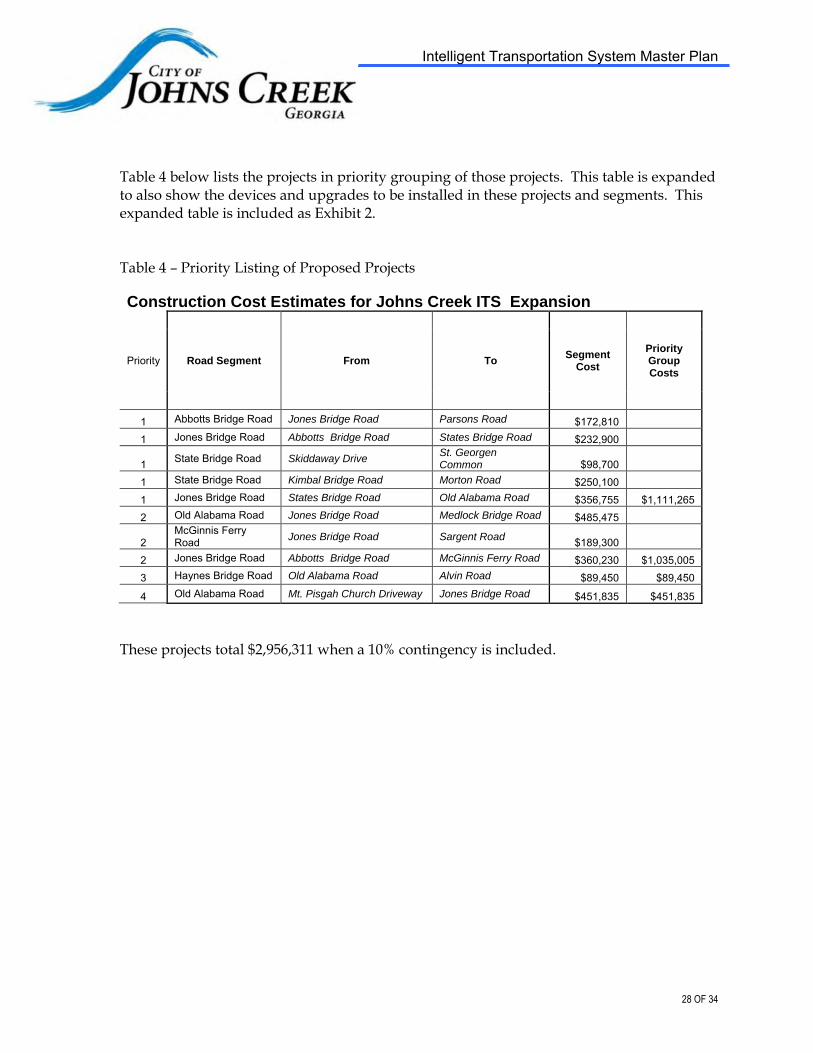
Intelligent Transportation System Master Plan
Table 4 below lists the projects in priority grouping of those projects. This table is expanded to also show the devices and upgrades to be installed in these projects and segments. This expanded table is included as Exhibit 2.
Table 4 – Priority Listing of Proposed Projects
Construction Cost Estimates for Johns Creek ITS Expansion
Priority Road Segment From To Segment
Cost
Priority Group Costs
1 Abbotts Bridge Road Jones Bridge Road Parsons Road $172,810 1 Jones Bridge Road Abbotts Bridge Road States Bridge Road $232,900
1 State Bridge Road Skiddaway Drive St. Georgen Common $98,700
1 State Bridge Road Kimbal Bridge Road Morton Road $250,100 1 Jones Bridge Road States Bridge Road Old Alabama Road $356,755 $1,111,265 2 Old Alabama Road Jones Bridge Road Medlock Bridge Road $485,475
2 McGinnis Ferry Road Jones Bridge Road Sargent Road $189,300
2 Jones Bridge Road Abbotts Bridge Road McGinnis Ferry Road $360,230 $1,035,005 3 Haynes Bridge Road Old Alabama Road Alvin Road $89,450 $89,450
4 Old Alabama Road Mt. Pisgah Church Driveway Jones Bridge Road $451,835 $451,835
These projects total $2,956,311 when a 10% contingency is included.
28 OF 34

Intelligent Transportation System Master Plan
Exhibit 1
Johns Creek Signalized Intersections
1. SR 120/Abbotts Bridge Road @ Boles Road 2. SR 120/Abbotts Bridge Road @ Sweet Creek Road 3. SR 120/Abbotts Bridge Road @ Northview High School 4. SR 120/Abbotts Bridge Road @ Parsons Road 5. SR 120/Abbotts Bridge Road @ Addison Way 6. SR 120/Abbotts Bridge Road @ Jones Bridge Road 7. Haynes Bridge Road @ Alvin Road 8. Haynes Bridge Road @ Publix 9. Jones Bridge Road @ Promenade
10. Jones Bridge Road @ Waters Road 11. Jones Bridge Road @ Buice Road 12. Jones Bridge Road @ Taylor Road 13. Jones Bridge Road @ East Fox Court 14. Jones Bridge Road @ Sargent Road 15. Jones Bridge Road @ Douglas Road 16. Kimball Bridge Road @ Ocee Elementary School 17. McGinnis Ferry Road @ Douglas Road 18. McGinnis Ferry Road @ Jones Bridge Road 19. McGinnis Ferry Road @ Seven Oaks 20. McGinnis Ferry Road @ Hospital Parkway 21. SR 141/Medlock Bridge Road @ Hospital Parkway 22. SR 141/Medlock Bridge Road @ Johns Creek Parkway 23. SR 141/Medlock Bridge Road @ Bell Road 24. SR 141/Medlock Bridge Road @ SR 120/Abbotts Bridge Road 25. SR 141/Medlock Bridge Road @ Skyway Drive 26. SR 141/Medlock Bridge Road @ Parsons Road 27. SR 141/Medlock Bridge Road @ Wilson Road 28. SR 141/Medlock Bridge Road @ Medlock Bridge Parkway 29. SR 141/Medlock Bridge Road @ St. Ives Country Club 30. SR 141/Medlock Bridge Road @ State Bridge Road 31. SR 141/Medlock Bridge Road @ Medlock Crossing Parkway 32. SR 141/Medlock Bridge Road @ Old Alabama Road 33. SR 141/Medlock Bridge Road @ Bobby Jones Drive 34. Old Alabama Road @ Buice Road 35. Old Alabama Road @ Country Club of the South/Hunts Pointe Drive 36. Old Alabama Road @ Autrey Mill Middle School/Cherbury Lane 37. Old Alabama Road @ Jones Bridge Road 38. Old Alabama Road @ Preston Oaks Drive/Breckenridge Close 39. Old Alabama Road @ Timberstone Road/Holy Redeemer 40. Old Alabama Road @ Brumbelow Road/Feather Sound Court
29 OF 34

Intelligent Transportation System Master Plan
41. Old Alabama Road @ Newtown Park/Fire Station 42. Old Alabama Road @ Haynes Bridge Road/Rod Road 43. Old Alabama Road @ Kroger/Old Alabama Crossing Shopping Center 44. Old Alabama Road @ Nesbit Ferry Road/Mt. Pisgah School 45. Old Alabama Road @ Mt. Pisgah Church West 46. Sargent Road @ Findley Road 47. State Bridge Road @ St. Georgian Place 48. State Bridge Road @ Parkway Baptist Church 49. State Bridge Road @ Home Depot 50. State Bridge Road @ Medlock Crossing Parkway 51. State Bridge Road @ State Bridge Elementary School 52. State Bridge Road @ Twingate Drive/ Morton Road 53. State Bridge Road @ Abberley Township 54. State Bridge Road @ Jones Bridge Road 55. State Bridge Road @ Kroger/Saddle Brook Shopping Center 56. State Bridge Road @ Ocee Elementary School 57. State Bridge Road @ Kimball Bridge Road
Flashing Caution Signals
1. Jones Bridge Road @ Barnwell Road
Vehicle Approaching Signs
1. Bell Road @ Rogers Circle
30 OF 34

Existing Fiber Network_DRT.dgn 1/6/2010 9:06:17 AM

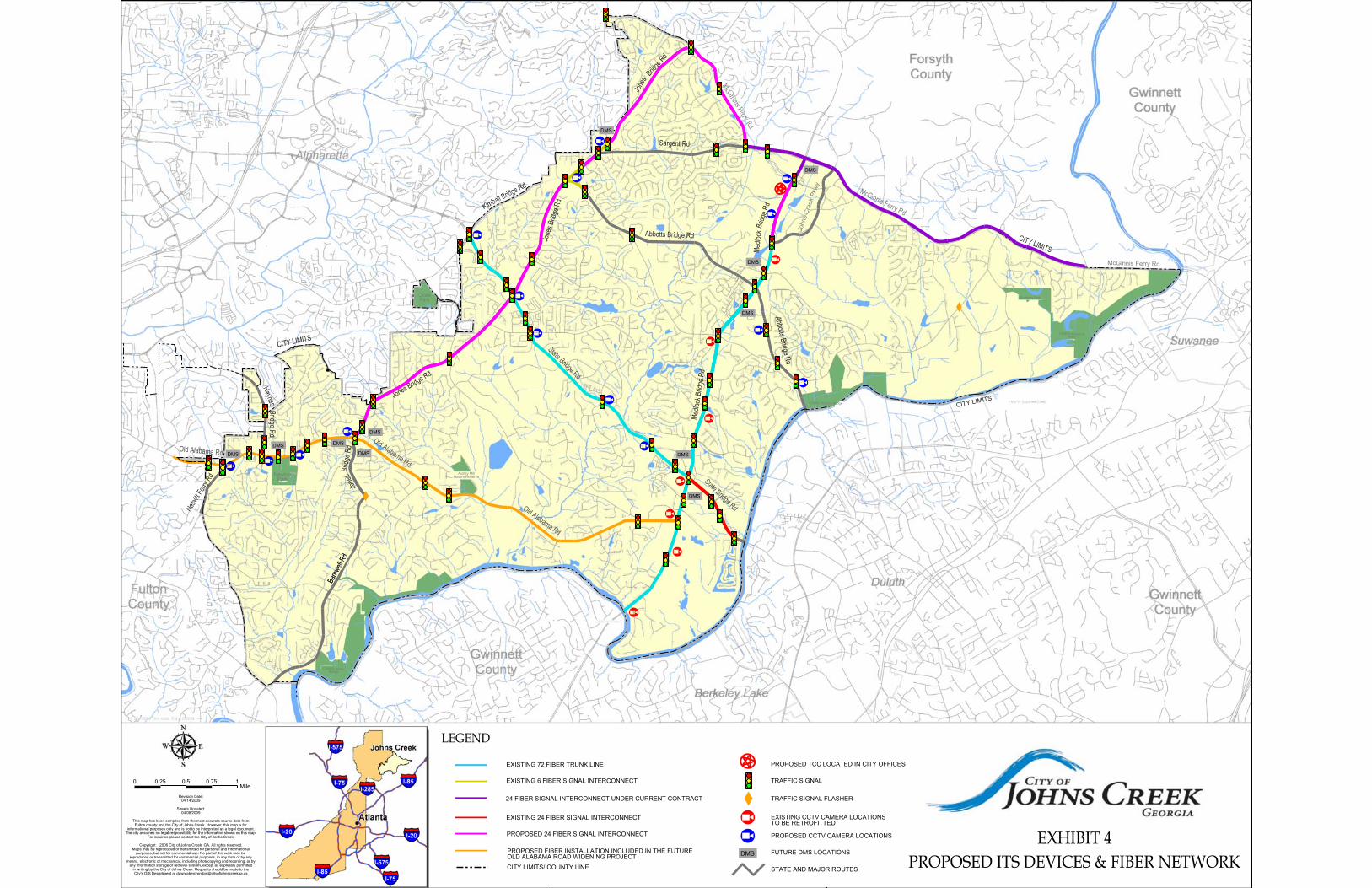
Proposed ITS Devices and Fiber Network_DRT.dgn 1/6/2010 4:48:54 PM

Co
nst
ruct
ion
Co
st E
stim
ate
s fo
r Jo
hn
s C
ree
k IT
S
Ex
pa
nsi
on
P
rop
ose
d A
lMS
De
vice
s
'0
Fibe
r O
ptic
M
lcro
wa
va
Mic
row
ave
C
hang
eabl
e R
oa
dw
ay
Ca
ble
ee
TV
eeTV
R
ad
ar
Prio
rity
Roa
d S
eg
me
nt
Flom
T.
L
engt
h L
en
gth
C
om
mu
nic
ati
ons
Qu
an
tity
C
am
era
(e
a)
Det
ecto
r R
adar
091
&1:
IIon
Mas
sag
e S
ign
{mil
{m
il
Qu
an
tity
(e
a)
Oua
n1lty
$9
5,5
00
$28
,200
S2
4.00
0 ,
Abb
ol1s
Bri
dg
e R
oa
d
Jone
s B
ridge
Roa
d P
arso
ns R
oad
0."
0.9
4 $
89.
770
, $5
6,4
00
$
0
0 ,
Jone
s B
ridge
Roa
d A
bbof
fs B
rid
ge
Ro
ad
S
lam
s B
ridge
Ro
ad
"
L.
$133
.700
,
$28
,200
,
$24
.000
,
, S
tate
B<i
dge
Roa
d $I
o:id
daw
ay O
rive
St
. G
80rg
en C
omro
on
, ... 0
$0
, $2
8,2
00
, $
24,
000
0 ,
Sla
te B
ridge
Roa
d K
imba
l Bri
dge
Roa
d M
orto
n R
oad
2.3
1 0
$0
• $
112
,600
3
$72,
000
, ,
Jone
s B
ridge
Roa
d S
tale
s B
ridg
e R
O<l
d O
ld A
lilba
ma
RO
ild
2.37
2.
37
$226
.335
,
$28
;20
0
, $4
8,00
0 ,
Old
A1i
lbam
a R
oad
Jone
s B
ridge
Roa
d M
9d/o
d< B
ridge
RO
<ld
"'5
3
.85
$367
,875
,
$56,
400
$0
,
, M
cGin
nis
FerIY
Roa
d Jo
nes
Br'd
ge R
oad
Sar
genl
Roa
d "
... $
13
3.70
0 ,
$28
,20
0
$0
0
, Jo
nes
Brid
ge R
oad
Abb
crts
Brid
ge R
oad
McG
inni
s F
erry
Roa
d 2.
02
2.0
2
$192
.910
,
$56.
400
, $4
8,00
0 ,
3 H
ayne
s B
rid>l
e R
oad
Old
Ala
bam
a R
oad
Alv
in R
oad
" 0
.' $4
7.75
0 ,
$2
82
00
$
0
• O
ld A
laba
ma
Roa
d M
r. P
isga
h C
hurc
h D
rive
way
Jo
nes
Brid
ge R
oad
'.69
1.69
$1
61.3
95
3 $8
4,60
0 3
$72,
000
•
Cha
ngea
ble
Ret
rofll
R
etro
fit
Tral
lie
Me
ssa
ge
Sig
n
Sig
na
l T
raff
ic
(ea
) Q
uant
ily
Sig
na
l (ea
)
$6
,80
0
o;,W
<>
$0
, $
13,
000
$13.
600
, $1
3.00
0
$0
, $
32,
500
16.8
00
, $
32,
500
$0
•
$26,
000
16,8
00
3 $
19.
500
$0
, $
13.
000
16.8
00
• $2
6,00
0
$0
, $6
,500
$27.
200
9 $
58.
500
Util
ity M
ake
Re
ad
y &
S
egm
ent
Cos
t M
isc.
$13
,64
0 $1
72.8
10
$20.
400
$232
,900
$14
,000
$9
8.7
00
$26,
000
$250
.100
$28,
220
$356
,755
$3
5,1
00
$4
85,4
75
$14
,40
0
$189
,300
$30,
120
$360
.230
$7,0
00
$89.
450
$48,
140
$451
.835
~
~~
~~
en Q
~t"r
j
E~
Pri
ori
ty G
rOtJ
p C
ost
s
$1.1
11.2
65
$1.
035.
005
$89.
450
$451
.835
Intelligent Transportation System Master Plan
Exhibit 5: Project Priority Listing
34 OF 34

Attachment 2

COST ESTIMATE
McGinnis Ferry, Abbotts Bridge (SR 120), and State Bridge
PI 0012626
Unit Price Total
150‐1000 TRAFFIC CONTROL ‐ 0010328 LS 1 $20,000.00 $20,000.00
615‐1200 DIRECTIONAL BORE ‐ 3 INCH LF 0 $6.20 $0.00
615‐1200 DIRECTIONAL BORE ‐ 5 INCH LF 18310 $8.00 $146,516.62
639‐1350 TREATED TIMBER POLE, CL 3, 50' EA 0 $1,608.98 $0.00
639‐2002 STEEL WIRE STRAND CABLE, 3/8" LF 1685 $3.23 $5,436.56
641‐1200 GUARDRAIL, TP W LF 0 $37.38 $0.00
641‐5001 GUARDRAIL ANCHORAGE, TP 1 EA 0 $1,137.21 $0.00
641‐5012 GUARDRAIL ANCHORAGE, TP 12 EA 0 $2,913.03 $0.00
643‐8200 BARRIER FENCE (ORANGE), 4 FT LF 0 $1.52 $0.00
647‐2130 PULL BOX, PB‐3 EA 0 $445.85 $0.00
647‐2141 PULL BOX, PB‐4S EA 20 $738.33 $14,766.52
647‐2170 PULL BOX, PB‐7 EA 13 $1,206.99 $15,690.84
681‐5115 LUMIN BRACKET ARM, 15 FT ARM EA 7 $859.89 $6,019.26
682‐6233 CONDUIT, NONMETL, TP 3, 2 IN LF 36620 $3.30 $120,846.00
682‐6236 CONDUIT, NONMETL, TP2, 2 IN LF 270 $11.27 $3,042.36
682‐9010 SVC POLE RISER EA 140 $968.89 $135,644.88
700‐9300 SOD SY 0 $6.36 $0.00
713‐3011 WOOD FIBER BLANKET, TP I, SHOULDERS SY 0 $1.36 $0.00
935‐1116 OUT PLNT FBR OPT CBL,LOOSE TB,SM,24 FBR LF 24400 $1.47 $35,916.80
935‐1512 OUT PLNT FBR OPT CBL,DROP,SM,6 FBR LF 300 $1.13 $340.44
935‐3106 FIBER OPTIC CLOSURE,UNDRGRD,24 FIBER EA 6 $591.48 $3,548.88
935‐3603 FBR. OP.CLOS.,FDC PRE‐TERM., TYP. A EA 5 $915.22 $4,576.09
935‐4010 FIBER OPTIC SPLICE, FUSION EA 144 $33.39 $4,808.54
935‐8000 TESTING LS 1 $10,000.00 $10,000.00
936‐1000 CCTV SYSTEM TYPE C EA 7 $7,788.78 $54,521.47
939‐2300 FIELD SWITCH, TYPE A EA 1 $2,327.57 $2,327.57
939‐2305 FIELD SWITCH, TYPE C EA 8 $1,641.76 $13,134.10
939‐5010 ELEC PWR SVC ASSEMBLY, AERIAL SVC POINT EA 0 $1,915.25 $0.00
639‐4004 STRAIN POLE, TP IV EA 0 $5,253.24 $0.00
999‐0001 Cabinet Type C (Pole Mounted) EA 2 $1,750.00 $3,500.00
999‐0002 Trace Wire LF 18110 $0.03 $543.30
$601,180.24
$30,059.01
$30,059.01
$661,298.27
ESTIMATE DATE:
9/9/2014
Engineering and Inspection (5%)
GRAND TOTAL
Contingency (5%)
Engineer's Estimate
SUBTOTAL
Item Number Item Description Unit Quantity

Attachment 3


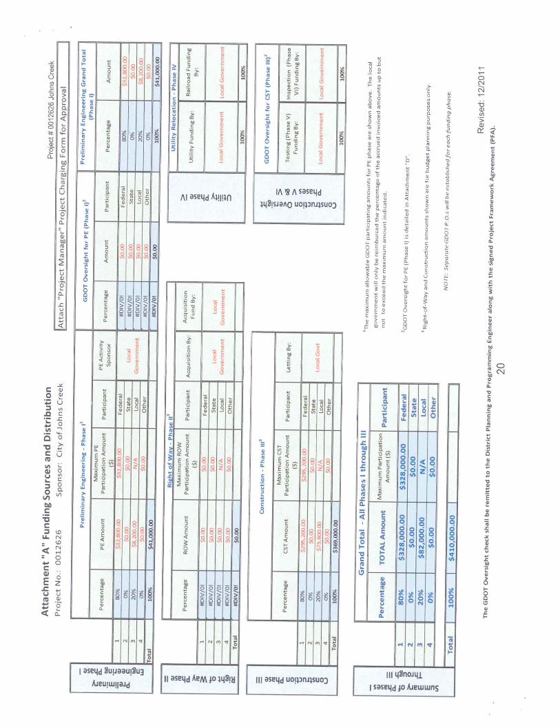
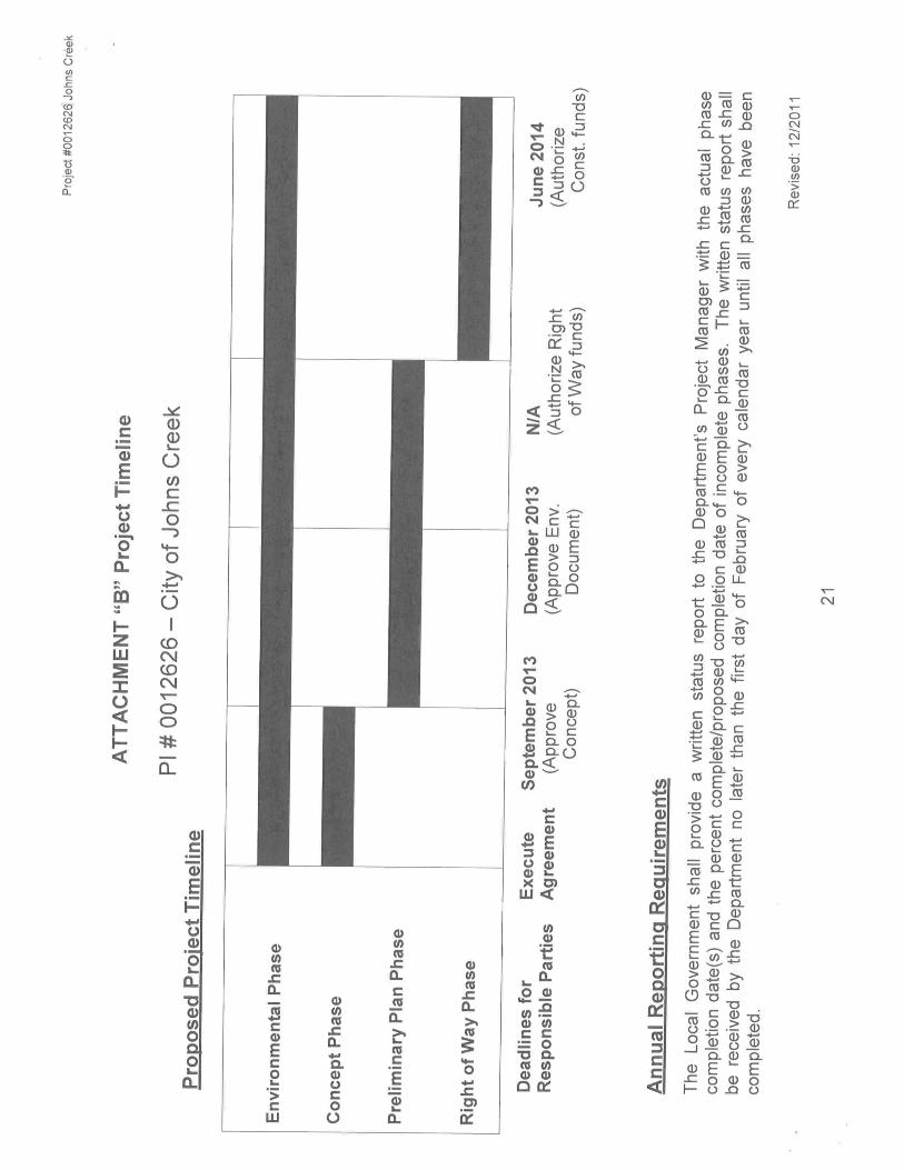
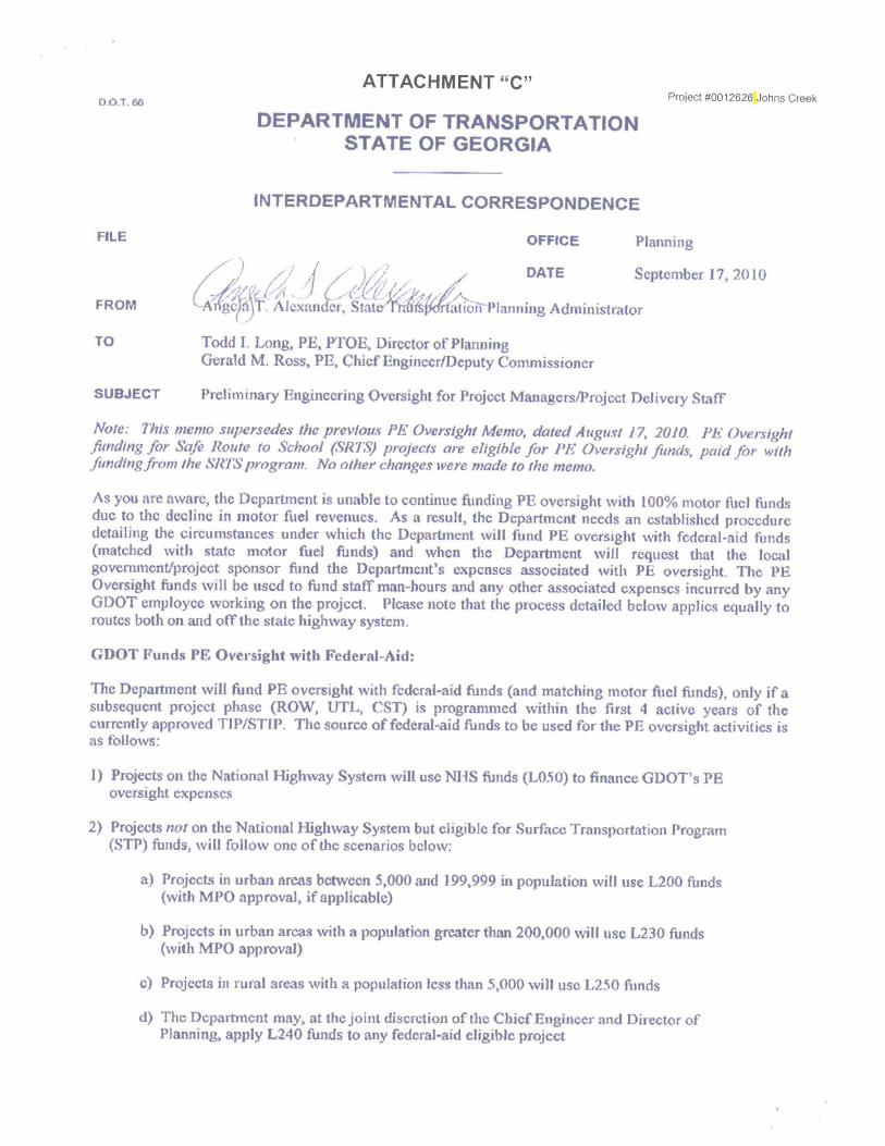


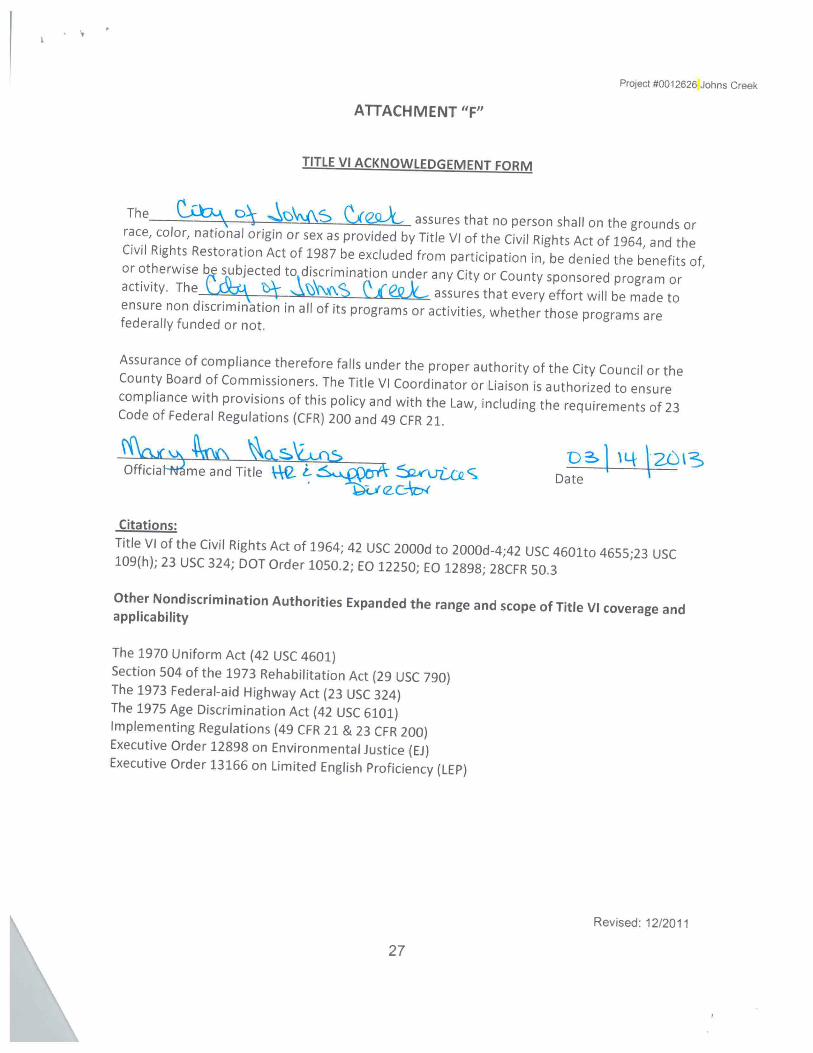

Attachment 4

ITS Phase 3A - PI#0012626 3/11/14 Attendees:
• Alex Hofelich, SEI • Cindy Jenkins, COJC • Chris Maddox, SEI • John Portwood, COJC • Tom Udell, COJC
Topics:
• Discussed schedule and balance between goal of May 2015 let date and goal of getting
a letter for advance funding if possible
• Discussed need for coordination with Gwinnett County
o Meeting to be scheduled next week with COJC, Gwinnett, GDOT PM, and SEI
o Need to add Gwinnett projects to concept report
o Need to discuss river crossing preferences
• Discussed impact of SR 120 project and potential modification to scope
o COJC to hold meeting 3/12 to determine next steps that project and how that will
impact PI#0012626
• Discussed several items in draft concept report that need to be adjusted
o Provided new paragraph discussing avoidance of signal permits and discussed
how and where to expand
o Additional redlines to be provided to COJC
• Discussed need to start environmental early coordination
o Aster survey completed in late 2013
• Cindy is to be CC'd on milestone items but not details
• SEI needs from COJC
o Copy of local let approval form
o Copy of Material Testing Request
o Determination of cost responsibility for utility relocation and make-ready work
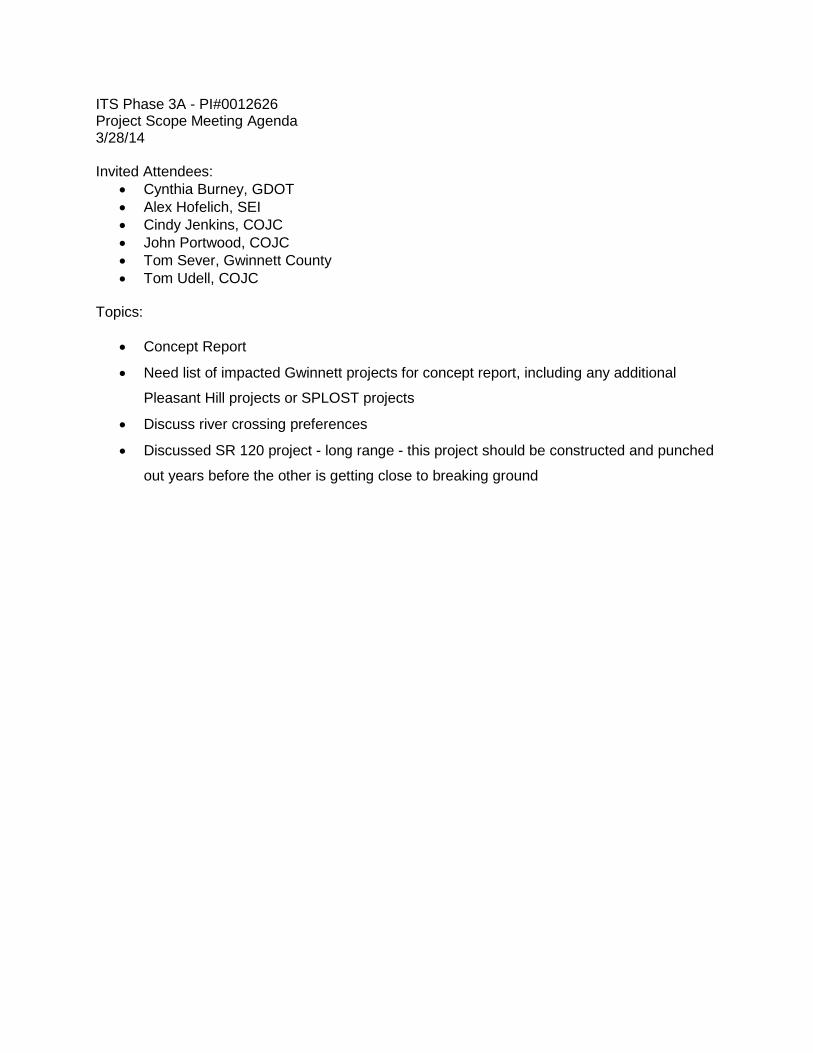
ITS Phase 3A - PI#0012626 Project Scope Meeting Agenda 3/28/14 Invited Attendees:
• Cynthia Burney, GDOT • Alex Hofelich, SEI • Cindy Jenkins, COJC • John Portwood, COJC • Tom Sever, Gwinnett County • Tom Udell, COJC
Topics:
• Concept Report
• Need list of impacted Gwinnett projects for concept report, including any additional
Pleasant Hill projects or SPLOST projects
• Discuss river crossing preferences
• Discussed SR 120 project - long range - this project should be constructed and punched
out years before the other is getting close to breaking ground