project report - industrial applications of plcs and drives
TRANSCRIPT

1
A PROJECT REPORT ON
PLCs AND DRIVES FOR AUTOMATION SYSTEM IN
INDUSTRIAL ENVIRONMENT
BACHELOR OF TECHNOLOGY
IN
ELECTRICAL AND ELECTRONICS ENGINEERING
Submitted By
RAGHAVENDRA M.R
Under the esteemed guidance of
Sri ADISESHANAIK
Sr. MANAGER (ETL DEPT)
VIZAG STEEL PLANT
DEPARTMENT OF
ELECTRICAL AND ELECTRONICS ENGINEERING
CMRIT
ITPL, BANGALORE

2
CERTIFICATE
This is to certify that the project work entitled “PLCs AND DRIVES FOR
AUTOMATION SYSTEM IN INDUSTRIAL ENVIRONMENT” is a
bonafide work carried out by Raghavendra M.R, student of CMRIT Engineering college
studying in 3rd
year
B.Tech. Department of Electrical and Electronics Engineering.
The project was carried out from 17th
Jul to 27
th Jul , 2013 and completed successfully
in the Department of Electro Technical Laboratory (ETL), Vizag Steel Plant,
Vishakapatnam successfully.
Sri Adhisesha Naik
Sr. Manager, ETL (LMMM)
3
ACKNOWLEDGEMENT
I extend my gratitude to The Head of the Department of Electrical and
Electronics Engineering of CMRIT Engineering College, Training and Development
Centre, Visakhapatnam Steel Plant for giving me this opportunity to undertake the
project.
I greatly acknowledge the assistance given by my Principal without which my
exposition to the inquisitive concepts in the project would have achieved.
I deeply acknowledge the support and never ending encouragement given by the
faculty of EEE department – CMRIT Engineering college to accomplish this task.
I express my deep sense of gratitude and indebtedness to Shri AdiseshaNaik, Sr.
Manager, Electro Technical Laboratory (ETL), Vizag Steel Plant for his inspiring
guidance, untiring efforts and constant encouragement, support and suggestions for
improvement during the course of my project.
I would like to convey my hearty gratitude to L.Jyothi Assistant Manager,
L.V.Ramesh Deputy Manager, ETL LMMM, Vizag Steel Plant for providing all
necessary facilities and helpful suggestions.
I also convey my wholehearted thanks to all in Vizag steel, faculty of our college and
other members who helped in bringing out this project.
Raghavendra M.R

4
Content
CHAPTER – 1
Overview of Visakhapatnam steel plant
CHAPTER – 2
Overview of LMMM
Bloom charging and discharging Equipment
Mill Equipment
CHAPTER – 3
Overview of GE-FANUC PLC
Networking of LMMM
Ethernet Switch
UTP Cables
Optical Fibers
Media Converters
CHAPTER – 4
Conclusion

5
RASHTRIYA ISPAT NIGAM LIMITED
VISAKHAPATNAM STEEL PLANT (VSP)
OVERVIEW OF VISAKHAPATNAM STEEL PLANT
Steel comprises one of the most important inputs in all sectors of economy.
Steel industry is both a basic and a core industry. The economy of any nation depends
on a strong bas of iron & steel industry in that nation. Iron & steel making, as India
has known a craft for a long time. The growth of steel industry in India can be
conveniently studied by dividing the period into pre & post independence era. By
1950, the total installed capacity for ingot steel production was 1.5 million tones per
year. The capacity increased by 11 folds to about 16 million tones by nineties.
Presently in India, steel products are being produced from 4 different sources, namely
Integrated steel plants, Mini Steel Plants, Re-rolling Mills, Alloy & special steel
Plants. In Integrated steel plants, naturally occurring raw materials are processed into
finished (steel) products in various stages. These plants are highly capital intensive. If
needs approximately Rs.2500 crores of money to establish a 1 million tonne per year
steel plant.
Visakhapatnam Steel Plant is an integrated steel plant, constructed with
former USSR collaboration. It is the first based and integrated steel plant constructed
in South India, with many modern technological features, some of them for the first
time in the country. Among these are:
7 Meter tall coke ovens
Dry quenching of coke
On ground blending of sinter base mix
Conveyer charging and bell less top for Blast Furnace
Cast house slag granulation for Blast furnace
100% continuous casting of liquid steel
Gas expansion turbine for power generation utilizing Blast Furnace top gas
pressure
Hot metal desulphurization

6
Extensive treatment facilities of effluents for ensuring proper environmental
protection
Computerization for process control
Sophisticated high speed and high production rolling mills.
The soviet design organization, GIPROMEZ designed the coke oven and coal
chemical plant, sinter plant and Blast Furnace. The seven meter tall coke oven
batteries with dry quenching were designed by MECON of Ranchi. The Remaining
facilities have been designed by DASTUR & CO, who are the principal consultants
for VSP.
Visakhapatnam steel plant has the following major production facilities:
3 coke oven batteries of 67 oven each having 41.6 cu.m volume
2 sinter machines of 312 Sq.m. area
2 Blast Furnaces of 3200 Cu.m useful volume
Steel Melt shop with three LD converters of 150T capacity
Light and Medium Merchant Mill of 710,000 tonnes per year capacity
Wire Rod Mill of 850,000 tonnes per year capacity
Medium Merchant & Structural Mill of 850,000 tonnes per year capacity
Captive power plant with a total generating capacity of 280 MW
Air separation plant for production of liquid Oxygen and Liquid Nitrogen
Extensive facilities have been provided for repair, maintenance as well as
manufacture of spare parts. There is a structural shop, Machine shop, foundry (with
wood working shop, forge shop), loco repair shop, Utility Equipment Repair shop.
There is Electrical Repair shop (ERS), for repair of Electrical Equipment like motors,
transformers etc.

7
ELECTRICAL & ELECTRONICS DEPARTMENTS OF VSP
VSP has got mainly three working divisions in each production departments.
1. Electrical
2. Mechanical
3. Operation
Shop electrical department is the owner of all electrical equipments in each
production/Maintenance zone. This department is headed with an HOD (E) and
will be reporting to concerned zonal in charge.
Electro Technical Laboratory (ETL) department is mainly responsible for
maintenance/breakdown analysis/commissioning activities/spare procurement for
all electronic related equipments in VSP. The equipments are Drives (AC/DC), PLCs,
UPS/SPS, CNC machines, Data Acquisition Systems. Each department shall have one
site in charge who reports to zonal officer. It has got a central laboratory where
repair of failed PCBs is done.
Instrumentation department is responsible for maintaining various gauges,
monitoring systems, transducers etc.,
The entire plant and township is well connected with local
telecommunication network. And also, in individual shop, there internal
communication system. All these are maintained by Telecommunication
department.
The Information Technology (System) department, though it is a special
department coming under Computer Engineering, can be considered as electrical
and electronics based upon the huge communication network they have in the
entire plant.
Technical Services (Electrical) department is mainly responsible for
analyzing the major breakdowns, condition monitoring of several equipment etc.,
Design & Engineering (Electrical) is responsible for preparing the
specification and coordinating with the customer department for up gradation of
obsolete equipments.

8
Central Maintenance Electrical department mainly deals with maintenance of
higher capacity electrical machines like HT motors.
Distribution Network (DNW) maintains High Tension electrical lines in the
plant.
Electrical Repair Shop (ERS) is responsible for repairing electrical machines
such as motors, transformers etc.,
INTRODUCTION TO TECHNOLOGICAL ADVANCEMENT
Any process can be classified into three basic units.
1. Power source
2. Control system
3. Driven system
During past several years, we find there is a stupendous advancement in the
control system technology. Where as the driven system and the Power source have taken
relatively less advancement. Few examples of control system are shown below
1. Programmable Logic Controllers (PLC)
2. AC/DC drives
3. Proportional controllers
4. CNC systems
5. UPS/SPS systems
DETAILS OF AUTOMATION SYSTEM IN VSP
LEVELS OF AUTOMATION IN LMMM:
Programmable Logic Controllers (PLCs) provided at level-1 finally control the
process equipment directly, each in its own area for sequencing and interlocking
functions. The system envisaged is interfaced with the main and auxiliary drive
analogue/digital control system so as to perform as one integrated unit.
The control at level-2 is basically decentralized and distributed in concept so as to
offer a higher degree of operational flexibility. A number of microcomputer subsystems
provided at this level, operate and control functions for the equipment distributed in
various areas of the mill.
9
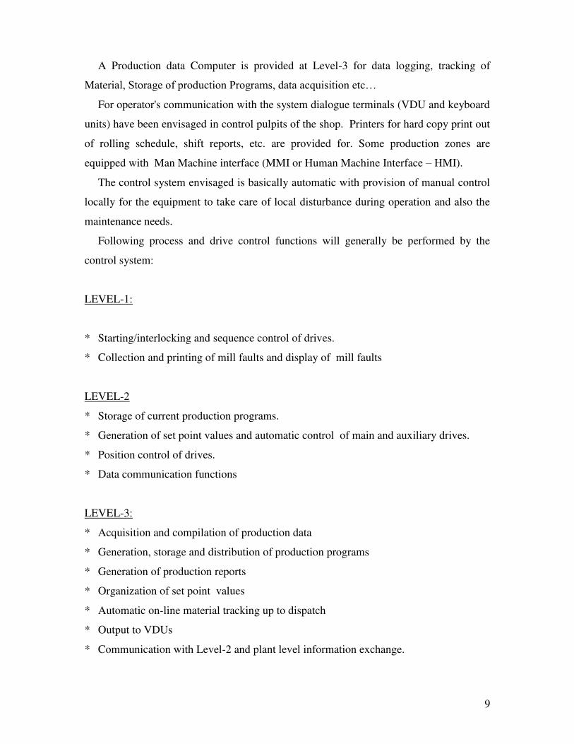
A Production data Computer is provided at Level-3 for data logging, tracking of
Material, Storage of production Programs, data acquisition etc…
For operator's communication with the system dialogue terminals (VDU and keyboard
units) have been envisaged in control pulpits of the shop. Printers for hard copy print out
of rolling schedule, shift reports, etc. are provided for. Some production zones are
equipped with Man Machine interface (MMI or Human Machine Interface – HMI).
The control system envisaged is basically automatic with provision of manual control
locally for the equipment to take care of local disturbance during operation and also the
maintenance needs.
Following process and drive control functions will generally be performed by the
control system:
LEVEL-1:
* Starting/interlocking and sequence control of drives.
* Collection and printing of mill faults and display of mill faults
LEVEL-2
* Storage of current production programs.
* Generation of set point values and automatic control of main and auxiliary drives.
* Position control of drives.
* Data communication functions
LEVEL-3:
* Acquisition and compilation of production data
* Generation, storage and distribution of production programs
* Generation of production reports
* Organization of set point values
* Automatic on-line material tracking up to dispatch
* Output to VDUs
* Communication with Level-2 and plant level information exchange.
10
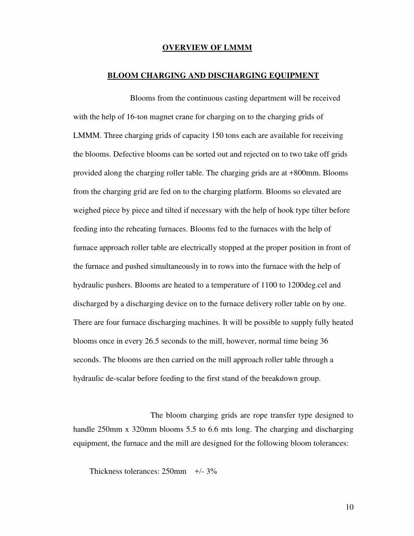
OVERVIEW OF LMMM
BLOOM CHARGING AND DISCHARGING EQUIPMENT
Blooms from the continuous casting department will be received
with the help of 16-ton magnet crane for charging on to the charging grids of
LMMM. Three charging grids of capacity 150 tons each are available for receiving
the blooms. Defective blooms can be sorted out and rejected on to two take off grids
provided along the charging roller table. The charging grids are at +800mm. Blooms
from the charging grid are fed on to the charging platform. Blooms so elevated are
weighed piece by piece and tilted if necessary with the help of hook type tilter before
feeding into the reheating furnaces. Blooms fed to the furnaces with the help of
furnace approach roller table are electrically stopped at the proper position in front of
the furnace and pushed simultaneously in to rows into the furnace with the help of
hydraulic pushers. Blooms are heated to a temperature of 1100 to 1200deg.cel and
discharged by a discharging device on to the furnace delivery roller table on by one.
There are four furnace discharging machines. It will be possible to supply fully heated
blooms once in every 26.5 seconds to the mill, however, normal time being 36
seconds. The blooms are then carried on the mill approach roller table through a
hydraulic de-scalar before feeding to the first stand of the breakdown group.
The bloom charging grids are rope transfer type designed to
handle 250mm x 320mm blooms 5.5 to 6.6 mts long. The charging and discharging
equipment, the furnace and the mill are designed for the following bloom tolerances:
Thickness tolerances: 250mm +/- 3%

11
Width tolerances: 320 mm +/- 3%
Diagonal differences: +/- 3.5 %
Deviations from straightness: Max. Permissible height of arc chord
Shall be 15 mm per meter measure Length, with
the total maximum of 80mm
Length tolerance: +/- 80 mm
The charging roller table and the furnace approach roller table are designed
with a speed of 1.2mts per second and the solid forged steel rollers are individually
drives. Bloom elevator (with one standby) is of chain type and has a cycle time of 21
seconds.
The in-line weigh scale has a weighing accuracy of +/- 0.1% of the net weight.
Hydraulic descaler is designed with a descaling pressure of 186 Kgs. At the end of
furnace delivery roller table an emergency hot bloom reject grid and pusher is
provided to remove defective blooms from the furnace. The defective blooms
collected by the mill crane can be taken back to the bloom storage yard with the help
of a transfer car. The bloom charging equipment are so designed that in case of
emergency the furnace can be emptied from the charging side by reversing the
walking beams of the furnace and discharging hot blooms on to the furnace approach
roller table. The furnace approach roller table, weigh scale, bloom elevator, the
charging roller table and reject grid are designed to handle the hot blooms emptied
from the furnace.
Mill equipment
Breakdown group: Breakdown group (billet mill part) has seven continuous
stands, with two horizontal stands 850 mm X 1200 mm followed by 5 alternate vertical
and horizontal stands, of which 3 are of 730 mm X 1000 mm and two are of 630 mm X
1000 mm. The total motor power for the breakdown group is 6,100Kw. The speed of
rolling is 1.3 to 1.6 mtr/sec.
An in-line four-crank shear, installed behind the breakdown group is designed to crop
both ends and to cut fixed billet lengths between 5 and 12.0 mts or to perform optimum

12
yield dividing. Billets fed to the bar mill are only cropped at the front and back ends,
while the billets for sale and for wire rod mill are cut to lengths 5 to 12 mts and 10.4 mts
respectively. When cutting fixed lengths, rest ends up to 1.5 mts are guided into the
scrap bucket and rest ends above 1.5 mts are transported over the closed recoil roller table
sections to a location where they are diverted into a short length disposal cradle.
Detection of rest end billet of above 1.5mts is performed automatically.
Billets rolled for sale and for wire rod mill are stamped in-line by a stamping machine
(with one standby) installed before the billet cooling bed in order to avoid cast mix-up.
If optimum yield cutting is performed, as in case of billets for wire rod mill, the total
finished length will be detected before the first length out is made. A quick computer
calculation decides the length before cutting in order to get three equal pieces and one
minimum crop cut at each end. Depending on the production programmed, blooms will
be rolled in sequence into billets for wire rod mill or sale and for the bar mill. The
standard rolling patterns for the bar mill (BM) and the billet cooling bed (CB) are:
a) All blooms to BM
b) All blooms to CB
c) One bloom to CB one bloom to BM (1:1)
d) Two blooms to CB two blooms to BM (2:2)
e) Three blooms to CB two blooms to BM (3:2)
f) Five blooms to CB two blooms to BM (5:2)
In addition to above, the following rolling patterns are also possible:
g) Two blooms to CB one bloom to BM (2:1)
h) Three blooms to CB one bloom to BM (3:1)
i) Five blooms to CB one bloom to BM (5:1)
Billet cooling bed and billet shear: The major facilities provided are the shifting
drum type transfer to shift cut-to-length billets on the move followed by two 12mts wide
turn over type billet cooling beds. Transfer of billets to the cooling beds is by feeder
screws which, after one full revolution, push the billet moving on the cooling bed roller
table sidewise to a break plate where it comes to rest after a short braking distance.
While the next billet is being delivered the billet resting on the brake plate is

13
simultaneously transferred through the feeder screw via short chute to the cooling bed
rake system. To ensure discharging of the billets coming in one by one a lead is
produced immediately at the back of the four crank shears to produce the defined gap
between the billets.
The cooling beds are designed as turnover type beds and consist of stationary and
moving rakes with notched surface. They are designed for 2-row covering with 5 to 6
mts and for single covering with 7 to 12m long billets.
During the turnover operation, the moving rakes turn the billets over 90deg in each
stroke, thus moving them on one pitch on the stationary rakes. Each cooling bed is
designed for a capacity of 200tons per hour to cool to approx. 400deg.cel with natural
convection. From the loading grid provided at the end of the cooling bed, billets will be
removed in batches by 16-ton capacity magnet cranes and stored in the intermediate billet
storage area.
Billets produced will have the following tolerance:
Billet size : 125 X 125 mm
Side length : +/- 2 mm
Edge round : 4 mm max
Straightness : 0.0025 X billet length
Length tolerance for 5-12 mts : +/- 25 mm
Fixed length : +/- 100mm
Billets rolled for bar mill are fed in full length to the two-strand roller hearth furnace
before feeding to the bar mill. A switch is arranged in front of the furnace to guide the
full length billets for bar mill, to either of the two strands.
Billets normally arrive at a surface temperature of about 1100deg.cel. at the roller
hearth furnace. In case of two-strand rolling, billets will be heated and soaked to the
discharging temperature of 1150deg.cel. At single strand rolling the billets will be heated
and soaked to a discharging temperature of 1130deg.cel. The temperature of the billets
when entering the first stand of the bar mill will be normally about 1100deg.cel. The
main drive and other connected equipment of the bar mill are, however, designed to roll
billets received at the first stand at a minimum temperature of 1050deg.cel.

14
The productivity of the furnace is 200 tones per hour both in case of single as well
as double-strand rolling. The furnace is also designed for oscillating billets inside the
roller hearth during stoppages.
Roughing group: The continuous multi-line bar mill comprises an eight-stand
roughing train, two five-stand intermediate trains and two four-stand finishing trains.
This mill arrangement permits to roll smaller size sections such as round, flats and angles
in two strands. In case of single-strand rolling it is also possible to prepare the complete
second intermediate and finishing mill for a new product size in a parallel rolling process.
The roughing group has one horizontal stand 610 X 1220mm, Three horizontal
stands 585 X 1220 mm and four horizontal stands 460 X 1060 mm. The total motor
power for the roughing group is 6000kw. The roughing group of stands have combined
gear box and pinion stands with casings of fabricated steel. Roll changing is by roll
changing rigs. Stands 5H to 8H can be retracted from pass line when not required for
rolling programmer.
Intermediate group: Intermediate group is arranged in multi-line arrangement.
Each line has five stands with four horizontal stands of 380 X 850 mm and one vertical
stand of 360 X 600 mm,. The motor power for each line is 4.300kw, i.e., a total of
8.600kw for the intermediate group. The advantages of the multi-line arrangement are
fully utilized for rounds 28 mm size, 25 mm squares and 40 mm channels. For all other
sizes the arrangement works like semi-multi line. The intermediate stands have
combined gear box and pinion stands with casing of fabricated steel. The roll changing is
done by complete stand changing with the help of quick stand-changing arrangement.
Finishing group: The two finishing groups are arranged to roll in single strand
only. Each finishing group has four alternate vertical and horizontal stand of 335 X 600
mm. The motor power for each line is 3,400kw i.e., a total of 6,800 kw for the two
finishing groups.
The finishing groups have combined gear box and pinion stands with casing of
fabricated steel. The roll changing is done by complete stand changing with the help of
quick stand-changing arrangement.

15
The total number of stands including those in the break-down group is 33. The
mill arrangement therefore, has the flexibility to adopt 24 to 29 passes as required by the
production programme. The roll neck bearings for all the stands are of anti-friction type.
The maximum finishing speed is 20 mts per second on 14 mm dia plain rounds.
Mill shear: Shears for cropping and emergency cutting are arranged ahead of the
first roughing stands and up-stream of the intermediate mill. Snap shears are arranged for
emergency cuts ahead of the finishing mills. A pinch roll unit is located adjacent to the
pendulum shear between the furnace and the first roughing stand. This pinch roll set will
be used in case feeding problems are faced on the first-stand of the roughing group. It
can also be used in case of mill troubles and after emergency cutting to feed the billet
remainder to the pendulum shear for size reduction into scrap pieces. In addition to
cutting multiple lengths as required by the rotary shear after the finishing stands, test-
piece can also be cut on this shear, which will be directed to the laboratory by a belt
conveyor. This rotary shear will be located after the water cooling stretch installed for
the TEMPCORE process. Space has been provided for locating one surface and one
dimension measuring unit between the last stand of the finishing group and the water
cooling stretch, in future.
Water cooling stretch: One cooling stretch is provided in each of the run-in
roller tables to the cooling beds immediately before the rotary shears. These cooling
stretches are such that reinforcing bars from 10mm to 25mm dia can be rapidly cooled
down from rolling temperature to a minimum temperature as per process know-how of
TEMPCORE to improve mechanical properties. Plain rounds from 12 mm to 40mm dia
also can be cooled to reduce secondary scaling. These cooling stretches are shiftable and
can be retracted from the pass line when other products are rolled.
Cooling bed: One double-sided rake type cooling bed is provided with 130 m X
11 m equivalent to an area of 1430 sq.m on each side. The double-sided cooling bed is
provided with row of axial fans. A switch is provided ahead of cooling beds permitting
both the cooling beds to be fed simultaneously when rolling in two-strands and the two
cooling beds in alternating order under single-strand rolling conditions. The run-in trough
16
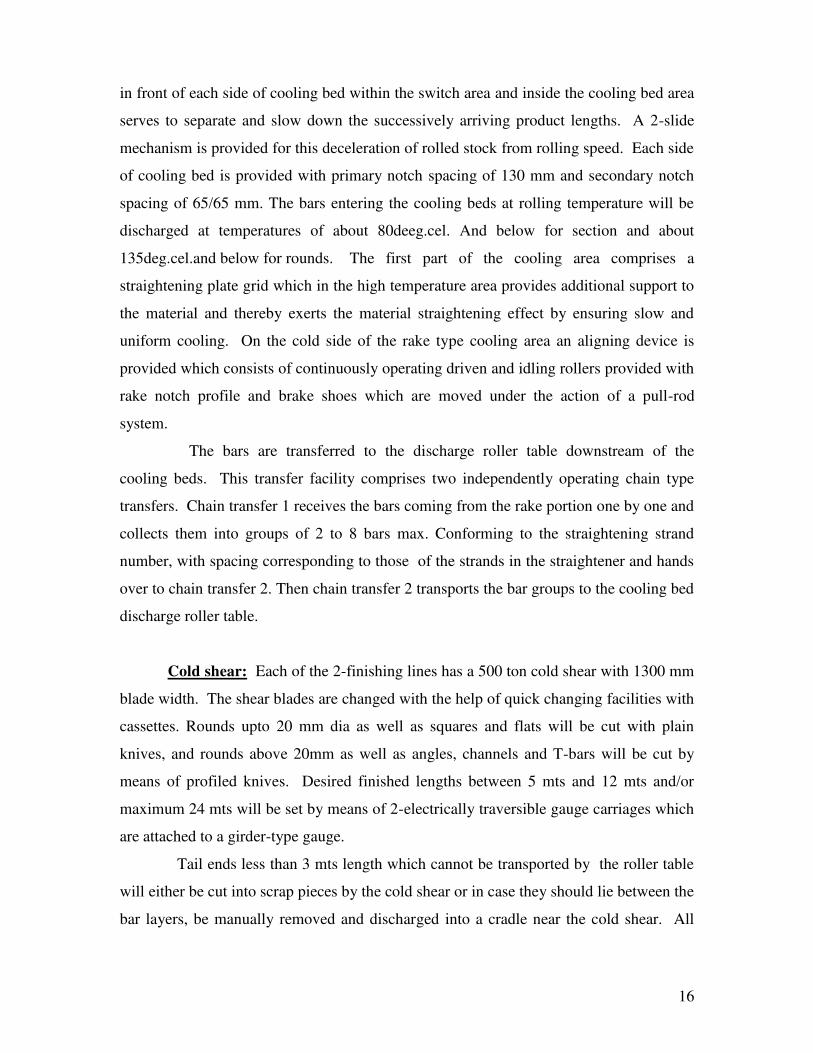
in front of each side of cooling bed within the switch area and inside the cooling bed area
serves to separate and slow down the successively arriving product lengths. A 2-slide
mechanism is provided for this deceleration of rolled stock from rolling speed. Each side
of cooling bed is provided with primary notch spacing of 130 mm and secondary notch
spacing of 65/65 mm. The bars entering the cooling beds at rolling temperature will be
discharged at temperatures of about 80deeg.cel. And below for section and about
135deg.cel.and below for rounds. The first part of the cooling area comprises a
straightening plate grid which in the high temperature area provides additional support to
the material and thereby exerts the material straightening effect by ensuring slow and
uniform cooling. On the cold side of the rake type cooling area an aligning device is
provided which consists of continuously operating driven and idling rollers provided with
rake notch profile and brake shoes which are moved under the action of a pull-rod
system.
The bars are transferred to the discharge roller table downstream of the
cooling beds. This transfer facility comprises two independently operating chain type
transfers. Chain transfer 1 receives the bars coming from the rake portion one by one and
collects them into groups of 2 to 8 bars max. Conforming to the straightening strand
number, with spacing corresponding to those of the strands in the straightener and hands
over to chain transfer 2. Then chain transfer 2 transports the bar groups to the cooling bed
discharge roller table.
Cold shear: Each of the 2-finishing lines has a 500 ton cold shear with 1300 mm
blade width. The shear blades are changed with the help of quick changing facilities with
cassettes. Rounds upto 20 mm dia as well as squares and flats will be cut with plain
knives, and rounds above 20mm as well as angles, channels and T-bars will be cut by
means of profiled knives. Desired finished lengths between 5 mts and 12 mts and/or
maximum 24 mts will be set by means of 2-electrically traversible gauge carriages which
are attached to a girder-type gauge.
Tail ends less than 3 mts length which cannot be transported by the roller table
will either be cut into scrap pieces by the cold shear or in case they should lie between the
bar layers, be manually removed and discharged into a cradle near the cold shear. All
17
tail- ends longer than 3 mts up to the relevant finished length will be directed to a
separate short separation device.
Strapping Machine is used for applying Straps over the rod bundles. Seven no. of
Strapping machines are there in LMMM. Strapping machines 1,2&3 come under control pulpit
9.Machines 4,5 & 6 come under control pulpit 10.Machine 7 is stand by.
Programmable logic controller (PLC)
A. Introduction
Generally speaking, process control system is made up of a group of electronic devices
and equipment that provide stability, accuracy and eliminate harmful transition statuses in
production processes. As a result of fast progress in technology, many complex
operational tasks have been solved by connecting programmable logic controllers and
possibly a central computer. Beside connections with instruments like operating panels,
motors, sensors, switches, valves and such, possibilities for communication among
instruments are so great that they allow high level of exploitation and process
coordination, as well as greater flexibility in realizing a process control system. In
automated system, PLC controller is usually the central part of a process control system.
With execution of a program stored in program memory, PLC continuously monitors
status of the system through signals from input devices. Based on the logic implemented
in the program, PLC determines which actions need to be executed with output
instruments. To run more complex processes it is possible to connect more PLC
controllers to a central computer.
A programmable logic controller (PLC) or programmable controller is a digital computer
used for automation of electromechanical processes, such as control of machinery on
factory assembly lines, control of amusement rides, or control of lighting fixtures. PLCs
are used in many different industries and machines such as packaging and semiconductor
machines. Unlike general-purpose computers, the PLC is designed for multiple inputs
and output arrangements, extended temperature ranges, immunity to electrical noise, and
resistance to vibration and impact. Programs to control machine operation are typically
stored in battery-backed or non-volatile memory. A PLC is an example of a real time
18
system since output results must be produced in response to input conditions within a
bounded time, otherwise unintended operation will result.
PLCs were evolved mainly as a replacement to relay logic. In addition to normal
sequential logic, complicated arithmetic calculations are also possible with the latest
architecture.
All PLCs are built around a Central Processing Unit (CPU) having a Processor or a
Micro controller. The processor is of a general purpose like Intel 8085 upto Pentium
versions. Some PLCs use special type of Micro controllers which are specific to the
make and model.
The main difference between a normal desktop Personal Computer (PC) and a PLC is,
PLCs are dedicated to a particular application. Once it is built for a specific purpose, it
cannot be used for any other job unless some changes are done.
The disadvantages of relay logic where no modifications are possible with power are
totally ruled out in a PLC based system. Any changes can be adopted online while the
process is going on and changes occur without any Process interruption.
All PLC systems are user friendly, micro level diagnostic features are available. Once
the user understands the syntax and the application, possibilities of error prone operations
are minimum.
DETAILS OF PARTS IN A PLC SYSTEM
A PLC System consists of the following parts
1. Mother board / base board / Module connectors
These are responsible for parallel communication between all the modules and
the CPU. Some systems support multiple boards where communication bus
will be extended using a parallel cable. All other modules will sit on this to
share the common bus.
2. CPU power supply
This module provides necessary power supplies required for CPU operation.
Basic power supplies are 5 / 3.6V, +/-12V, +/-15V, 24V
3. Interrogation Power supply
This power supply is required for actuating the field devices (relays,
contactors etc…) and acquiring the signal from field sensing instruments

19
(Metal detectors, proximity switches etc…). The voltage level varies
depending upon the application. Typical voltages used are, 24V, 48V. 60V,
220VAC etc…
4. Arithmetic Logic Unit (ALU) – Processor
Main processor unit where all logical, arithmetical etc… operations take
place.
5. Memory module
Some PLCs have inbuilt memory inside the Processor itself. If it is required to
expand the capacity of the memory, additional Memory modules are required.
The capacity is limited only depending upon the Processor used.
6. Digital Input / Output modules
Digital Input modules are used to sense the field signals. These convert
interrogation supply to TTL level (5V/3.6V).
Digital Output modules are used to actuate the field devices. These convert
TTL level to interrogation supply.
The total number of I/O handling capacity of a PLC is dependent on the type
of PLC used.
7. Analog Input / Output modules
Analog input modules convert a voltage signal ( 0 to +/-10V) or a current
signal (0 or 4 to 20ma) to digital form and store in a register.
Analog output modules convert digital word to either analog voltage or
current signal
8. Communication modules
These are responsible for communication with Programming Unit (also called
PG unit) to upload/download program, diagnosis purpose etc…
9. Application specific modules
Apart from digital and analog modules, some application needs for a special
modules like, Arithmetic processor, Ethernet module, Counter module etc…
The usage depends on the application.
10. Software for communication / modification / analysis of the system

20
Any PLC requires a way to communicate with the PG unit. This is done
through a software provided by the PLC manufacturer and a cable which
connects between PLC and the PG unit.
ARCHITECTURE OF A PLC
The Central Process Unit consists of following functional parts
1. Arithmetic Logic Unit
2. Decoding circuit
3. Timing circuit
4. Registers
5. Interrupt handling
6. Memory management
7. Communication
8. Interfacing units
The input system consists of Digital, Analog and counter units. Output system is
constituted with Digital and Analog output modules. The memory (external) will be
shared with CPU for its internal usage and two way communication exists. In some PLC
systems, there will be hand shaking signals which confirm the healthiness of each
module. In such PLCs, there will be two way communication system exists between ALU
and I/Os. The power supply feeds to I/Os and as well as CPU and related modules at bus
level.
CLASSIFICATION OF PLC SYSTEMS
There are basically three types of PLC systems.
1. Sequential
2. Modular
3. Real time
Sequential PLC systems are those where only one CPU exists with I/O modules. No
special module exists. All operations are carried out by the main CPU only.

21
In modular PLC system, special modules are used to carry some critical functions.
They function on their own data and only communicate to main PLC for healthiness and
other purpose. Arithmetic processors, motion controllers are some examples of such
modules. In such PLC systems, various time critical tasks are handled independently by
these special modules reducing the burden on the main Processor.
In Real Time based PLC systems, the total job is divided into several sub tasks.
All tasks are operated on a time division basis, so that, to the user, it looks like all are
being operated simultaneously. Just like a multi tasking operating system (Windows XP
and others), the execution of each task will be faster. Multiple CPU modules and
multiple interrupts are also possible with such systems.
BASICS OF PLC CONFIGURATION
To build a PLC system, one should know about the requirement of Hardware and
Software
In Hardware, following points are to be taken care
1. Number of I/Os
This is the main requirement to build a PLC system. Along with the number
of I/Os (digital and analog), knowledge on operation of the equipment is also
important
2. Memory requirement
There is no proper thumb rule to calculate the memory required for a
particular application. Approximation to be done with past experience.
3. Processor type
This depends upon the criticality of the application. Knowledge about
interrupt handling, DMA handling is required to select the Processor type for
a particular application.
4. Power supply
It is very important to decide the interrogation supply required for any
application. Care should be taken for selecting the load current in designing
the power supply rating.
Coming to software requirement, following point are to be considered
22
1. Modes of addressing
Different PLCs provide different way of addressing to Digital/analog I/Os and
also for other special I/Os. Knowledge about the addressing modes provided
by the PLC manufacturer is required
2. Application software
This is the one which is used for developing the application program to run
the job successfully. Different PLC manufacturers provide different software
packages to interact with PLC and to develop application software offline.
Most of the softwares are MS-Windows and DOS based.
3. Diagnostic features
All latest PLC systems provided micro level diagnostic features. User can
know the faults at discrete bit level.
4. Configuration of the system
Many PLC suppliers provide configuration of the PLC through software. This
is useful in modifying and system if required in future when application
demands
ADDRESSING MODES USED IN DIFFERENT PLCs
There are three types of addressing modes available
1. Mother boards
There are two types of Mother boards.
1. Passive
2. Active
Passive mother boards shall have only parallel bus extension. CPU
communicates with all modules through this bus. Each slot shall have unique
bus to identify the module in that particular card.
Active mother boards will have addressing features. The address decoding
part is available in such mother boards
2. Module addressing
Dip switches are provided at each card. These switches are to be set
accordingly to use in any location.
3. Software addressing

23
This is the advanced feature the latest PLC system is offering. All addressing
will be automatic and option is available for changing if required. The
moment any module is attached to the system, address will be assigned and
user has to use that part for accessing the module
DETAILS OF PROGRAMMING IN A PLC
Two types of jobs are involved with any PLC system. Offline activities include
preparation of application program and hardware configuration. All communication
configurations are also done offline. In this case, the PLC shall not be in RUN mode. Few
PLC system provide flash ram/ Eeprom etc.. to store the configuration as a back up
permanently which can be overwritten in future. Such operations are also done offline.
Online operations include, forcing of memory bits including I/Os. Other user memory
part like registers can also be altered during online. Minor changes of application
program can be made.
DETAILS OF OPERATION IN A PLC
Basically, there are two modes for any PLC system, Run and stop. In Run mode, PLC
will execute the logic, read the inputs and produce outputs. PLC will take certain amount
of time to read inputs, execute the logic and produce the outputs. This time is called cycle
time of PLC. The execution in a flow diagram can be seen as, Start input scan Logic
scan Output scan User application Communication System scan Timer
operation Stop
DETAILS OF PROGRAMMING LANGUAGES USED IN PLCs
Different software languages are available to program a PLC. Few of these include
Ladder diagram
Statement list
Control system flow
Function block diagram
Few PLC systems allow to program using higher level languages like Visual C,
Visual Basic, C, Pascal etc… Few PLCs can be programmed using Assembler program also.
24
COMMUNICATION SYSTEMS IN PLCs
Different types of communication systems are adopted by different PLC
manufacturers. Following are the list of few such systems.
Siemens:
1. Profibus
2. MPI – Multi point interface
3. OPI – Operator interface
4. Ethernet
GE-Fanuc:
1. RS-232
2. Ethernet
3. Genius Bus
Allen Bradely:
1. Device net
2. Control net
3. Ethernet
DIFFERENT TYPES OF PLCs USED IN VSP
Following are few different type of PLCs which are being used in VSP.
1. Siemens – S7-200, S7-300
2. Allen Bradely – SLC, Control logix, Flex logix
3. GE-Fanuc – Versa max, 90-30
4. Telemecanique – Series TSX
5. AEG – Quantum, CP80-A800
6. Honey well – Series 620
25
MAN MACHINE INTERFACE
Earlier days, all commands from operator desk (Control Pulpit) are wired to
automation systems (PLCs and other equipments) through push buttons, data key boards
and other physically mounted devices. That made to increase the wiring more and
cumbersome to maintain. The present automation system involves Man Machine
Interface (MMI) or Human Machine Interface (HMI) or Man Machine Communication
(MMC) systems. The total wiring got reduced and the communication between operator
and the automation system is through Ethernet(OFC or UTP), or proprietary
communication bus.
The latest MMI systems are built on Server and client based architecture. MMI few
systems which are being used in VSP are shown below
1. RS View For Allen Bradely systems
2. Win CC For Siemens systems
3. Complicity for GE-Fanuc systems

26
DETAILS OF GE-FANUC PLC
The basic parts in the PLC are
- Base plate
- Power supplies
- CPU’
- Digital I/O Modules
BASE PLATES:
The base plates are the foundation of PLC system because most other components
mount on them. As a basic minimum , every system has at least one base plate which
usually contains the CPU (in which case ,it is referred to as “the CPU base plate”).Many
systems require more modules than can be mounted on one base plate ,so there are also
Expansion and Remote base plate that connect together.

27
The different categories of base plate are:
CPU
Expansion
Remote
Each of these is available in two sizes, 5-slot and 10-slot, named according to the number
of modules they can hold.
DIGITAL I/O MODULES:
24 VDC Positive/Negative Logic, 32 Point Input IC693MDL655:
The 24 volt DC Positive/Negative Logic Input module for the Series 90-30
Programmable Logic Controller provides 32 discrete input points. The inputs are
arranged in four isolated groups of eight (A1 - A8, B1 - B8, C1 - C8, and D1 - D8).The
inputs are positive or negative logic inputs and will operate at levels up to 30V.Backplane
isolation between the field side and logic side is provided by up to-couplers on the
module. Isolation is also provided between the four groups of inputs on the module,
however each group of eight inputs is referenced to the same user common connection.
There are no special faults or alarm diagnostics reported. LED indicators (labeled A1-
A8, B1 - B8, C1 - C8, D1 - D8) at the top of the module provide the ON/OFF status of
each input point. This module is configured as a 32-point input type and uses 32 bits of
discrete %I input data. Current into an input point results in a logic 1 in the input status
table. Power to operate field devices can be supplied by the user, or from the isolated +24
VDC supply available at the module’s I/O connectors. This module can be installed in
any I/O slot of a 5 or 10-slot base plate in a Series 90-30 PLC system. Connections to the
input circuits are made from the user’s input devices to two male (pin-type) 24-pin
connectors (Fujitsu FCN-365P024-AU) mounted on the front of the module.

28
Circuit diagram of input module:

29
POWER SUPPLY MODULES:
Every base plate whether a CPU ,Expansion ,Remote base plate and whether a 5 –
slot or a 10 – slot size , must have its own power supply. The power supply always mount
in a base plate’s left most slot. There are several power supply modules available to meet variety of requirements.
SPECIFICATIONS OF GE-FANUC PLC:
PARAMETERS
RANGE
Rated Voltage
24 volts DC, Positive or Negative Logic
Input Voltage Range
0 to 30 volts DC
Inputs per Module
32 (four groups of eight inputs each)
Isolation
1500 volts between field side and logic side
250 volts between groups
Input Current
7.0 mA (typical ON current @ 24 VDC)
On-state Voltage
11.5 to 30 volts DC
Off-state Voltage
0 to 5 volts DC
On-state Current
3.2 mA (minimum)
Off-state Current
1.1 mA (maximum)

30
On response Time
2 ms maximum
Off response Time
2 ms maximum
Internal Power Consumption
195 mA (maximum) from +5V bus on
backplane ; (29 mA +0.5 mA/point ON +4.7
mA/LED ON)
224 mA (typical) from isolated +24V bus on
backplane or from user input supply @ 24
VDC
and all 32 inputs ON)
Figure12, Block diagram of PLC programming
Two types of jobs are involved with any PLC system. Offline activities include
preparation of application program and hardware configuration. All communication
configurations are also done offline. In this case, the PLC shall not be in RUN mode. Few
PLC system provide flash ram/ EPROM etc. to store the configuration as a back up
permanently which can be overwritten in future. Such operations are also done offline.
ONLINE OFF LINE
LOGIC
FORCING
USER MEMORY
HARDWARE
FLASH STORAGE
COMMUNICATION SETUP
SETUP

31
Online operations include, forcing of memory bits including I/Os. Other user memory
part like registers can also be altered during online. Minor changes of application
program can be made.
DETAILS OF OPERATION IN A PLC
Basically, there are two modes for any PLC system, Run and stop. In Run mode, PLC
will execute the logic, read the inputs and produce outputs. PLC will take certain amount
of time to read inputs, execute the logic and produce the outputs. This time is called cycle
time of PLC.
The execution steps to interface PLC with PC:
STEP-1:
Selection of VERSAPRO software
VERSAPRO is programming software developed with GE-Fanuc PLC.
STEP-2:
Create a new folder
HARDWARE CONFIGURATION:
Hardware configuration consists of configuring power supply, CPU ,Input-output
modules with required specifications.
STEP-3:
3.1 Go to VIEW → HARDWARE CONFIGURATION.
3.2 Go to EDIT → MODULE OPERATION → REPLACE MODULE
The above step is used to configure CPU and Power supply as required

32
I/O MODULES
3.3 Go to EDIT→ MODULE OPERATION → ADD MODULE
This step is used for including I/O modules if required.
COMMUNICATION SET-UP :
STEP–4:
4.1 Go to TOOLS → COMMUNICATION SET UP
4.2 Specify the device model and port type
If the communication is through ETHERNET then IP Address is also required.
STEP-5:
Draw the ladder diagram by selecting the components required and name the
components
STEP-6:
Now connect PLC
Go to PLC → CONNECT
STEP-7:
RUN the program and STOP by enabling outputs.
STEP-8:
STORE the program to PLC.
If any errors, information window will appear indicating the errors.
NOTE:
Verify whether the logic equals or not.
STEP-9:
5
6
7
8
9
1
0
4
3
1
2
Power CPU
supply
33
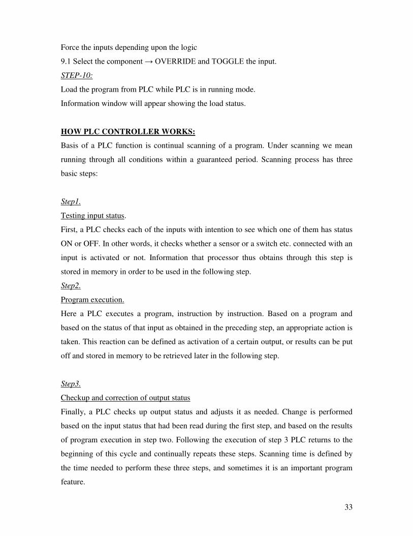
Force the inputs depending upon the logic
9.1 Select the component → OVERRIDE and TOGGLE the input.
STEP-10:
Load the program from PLC while PLC is in running mode.
Information window will appear showing the load status.
HOW PLC CONTROLLER WORKS:
Basis of a PLC function is continual scanning of a program. Under scanning we mean
running through all conditions within a guaranteed period. Scanning process has three
basic steps:
Step1.
Testing input status.
First, a PLC checks each of the inputs with intention to see which one of them has status
ON or OFF. In other words, it checks whether a sensor or a switch etc. connected with an
input is activated or not. Information that processor thus obtains through this step is
stored in memory in order to be used in the following step.
Step2.
Program execution.
Here a PLC executes a program, instruction by instruction. Based on a program and
based on the status of that input as obtained in the preceding step, an appropriate action is
taken. This reaction can be defined as activation of a certain output, or results can be put
off and stored in memory to be retrieved later in the following step.
Step3.
Checkup and correction of output status
Finally, a PLC checks up output status and adjusts it as needed. Change is performed
based on the input status that had been read during the first step, and based on the results
of program execution in step two. Following the execution of step 3 PLC returns to the
beginning of this cycle and continually repeats these steps. Scanning time is defined by
the time needed to perform these three steps, and sometimes it is an important program
feature.

34

35
DETAILS OF PROGRAMMING LANGUAGES USED IN PLCs
Different software languages are available to program a PLC. Few of these include
1. Ladder diagram
2. Statement list
3. Control system flow
4. Function block diagram
Few PLC systems allow to program using higher level languages like Visual C, Visual
Basic, C, Pascal etc Few PLCs can be programmed using Assembler program also.

36
CONCLUSIONS
In VSP, LMMM produces Rounds, Rebars, channels, angles etc…. For this
process various electronic equipment are required which include machines. To
control these machines PLCs are used which are a part of automation process. PLC
accepts inputs from switches and sensors, evaluates these in accordance with a stored
program, and generates outputs to control machines and processes.
There are many makes of PLCs available for industrial usage. Among them
GE - PLCs are widely used.
In this project we studied how to control the machines used in wire rod mill
using GE – Fanuc PLCs (90 – 30 model). In this PLC, for the purpose of
communication between programmable controllers ,distributed i/o stations, HMI
devices and numerous other field devices we use Genius bus. There are many types
of . These GE – Fanuc PLCs have very useful expansion facilities like
comprehensive communication, networking possibilities and user friendly handling.
It has essential features like modularity, multi computing, engineering and diagnostis.
These are playing a vital role. They are very reliable in their performance like
accuracy, speed and adaptability.
These PLCs can be expanded with latest versions i.e., state of art technology
to improve memory capability, I/O handling capability and versatility.
HMI communication is done through Cimplicity networking for various
automation units like servers, clients, display boards etc… Standard Ethernet network is used for communication as it is an open system.