prolyte mpt-tower manual assembly instructions · · 2007-10-29prolyte mpt-tower manual ... the...
TRANSCRIPT
Prolyte MPT-Tower Manual Assembly Instructions
Prolyte Products Group © 2002 page 1 of 12 Prolyte has made every effort to ensure the accuracy of this manual, no liability will be accepted for errors.
Prolyte reserves the right to change or alter their products or manuals without prior notice. No part of this manual may be reproduced in any form or by any means without prior written permission.
Prolyte Products Group · phone: +31-594-851515 · fax: +31-594-851516 · www.prolyte.com
Make sure to read and fully understand this manual, and its specific notes and warnings, prior to assembly and erection of the structure.
Contents: 1 System Description 2 Limitations of use 3 Scope of use 4 Identification, Parts 5 Dimensions & loading 6 General information 7 Assembly instructions 8 Additional assembly requirements for a stand alone tower 9 Additional assembly requirements for a goal post set up 10 Additional requirements for outdoor use 11 Spare parts 12 Declaration of conformity, CE-Mark 1. SYSTEM DESCRIPTION The Prolyte Tower & Ground Support systems are lifting tools where the load is constrained in its horizontal movement by means of a Sleeve block, that is build around, and lifted along, the tower sections. The MPT-Tower has a loading capacity that is limited by the lifting machinery: 750 kg for the hand winch, or 1000 kg for an electric or hand operated chain hoist. In general towers and ground support systems are used where the lifting of loads from a building structure is impossible, very expensive, or when traditional telescopic winch stands do not have a sufficient in load capacity. MPT-Towers use a vertical mast of standardized H30V truss as compression absorbing elements, these have much better strength and stability characteristics than traditional stands. 2. LIMITATIONS OF USE The MPT tower system is to be used with Prolyte trusses only. Loads to the trusses and towers shall be vertical only, no side loading is allowed to the system. The MPT system is designed as temporary lifting structure for indoor use only. When used outdoors or when horizontal loading is applied appropriate measures, such as placing guy-wires (cable-stays) and ballast, have to be taken to ensure stability. The MPT system is to be built by competent and trained persons only. For all other applications contact your local dealer or Prolyte. 3. SCOPE OF USE Prolyte’s MPT-towers are designed for the lifting of truss spans over stages, dance floors, exhibition area’s etc, where equipment such as lighting-, sound-, drapes or decoration elements is suspended. This can either be a single (stand-alone) Tower, a Goal post configuration (two towers with a single span) or in a rectangular set ups with 4, 6 tower ore more.
PROLYTE MPT-TOWER MANUAL ASSEMBLY INSTRUCTIONS
Prolyte MPT-Tower Manual Assembly Instructions
Prolyte Products Group © 2002 page 2 of 12 Prolyte has made every effort to ensure the accuracy of this manual, no liability will be accepted for errors.
Prolyte reserves the right to change or alter their products or manuals without prior notice. No part of this manual may be reproduced in any form or by any means without prior written permission.
Prolyte Products Group · phone: +31-594-851515 · fax: +31-594-851516 · www.prolyte.com
The spans of the trusses must NEVER exceed permissible length or load values given in the loading tables for the specific type of truss. MPT-towers are to be built to a maximum height of 7,5m. The total weight on the tower including, load, sleeve block and trusses must NEVER exceed 750 kg when using the hand winch or 1000 kg when using a chain hoist1. Prolyte-MPT towers comply with the European Machine Directive and bear the CE-mark. MPT-systems are designed for indoor use, for outdoor use please contact your local dealer or Prolyte. 4. IDENTIFICATION The MPT-tower is composed of the following parts: 1. Mast sections H30V 5,1 kg/m max. height 7,5 m 2. Base section MPT-004 26 kg made of steel hollow sections with castors 3. Sort outriggers MPT-011 2 kg short outriggers with screw jacks
Long outriggers MPT-012 12 kg long outriggers with screw jacks Stabilizer tube T-51-PI094ST 1,5 kg
4. Top section MPT-009 11 kg Pulleys suited for 8mm steel wire or up to 8 mm chain links
5. Hinge set CCS6-H 2 kg 4 hinges per tower needed 6. Hand winch MPT-014 23 kg WLL 750 kg. Needs adapter for mounting.
Hand chain hoist MPT-015 24 kg WLL 1000 kg. Electrical chain hoist CH-SM10-1004 45 kg WLL 1000 kg. Excluding chain. Chain for hoist 1,6 kg/m1 Chain 6.8mm for hoist
7. Sleeve block MPT-010 44 kg Suitable to fit all MP trusses and S36R/V truss. Optional components: 8. MPT-SAFE 14 kg Safety set to dead hang the sleeve blocks.
Per set 2 x MPR-009 and 2 clutches (CH-07-200HCH).
9. Adapter for S36R/V MPT-A-S36R/V 6,3 kg Adapter Plate to connect S36R/V truss to sleeve- block
The embossed ring on the ends of the conical coupler receivers, and stickers featuring the Prolyte logo can clearly identify the MPT towers and truss.
1 In systems composed of two (2) towers or more, all lifting the same truss or grid, it is mandatory in Dutch Law to reduce the lifted load to 75% of the rated capacity, thus max. 525 kg per tower with hand winch or max 750 kg per tower with 1 ton chain-hoist.
NOTE Make sure the system is built only of genuine Prolyte components, which are clearly and positively identified as Prolyte products. Copies do exist, and even though they may appear to fit to Prolyte trusses, they do not have identical strength and safety characteristics.
WARNING Prolyte MPT-towers are not designed to lift people!
Prolyte MPT-Tower Manual Assembly Instructions
Prolyte Products Group © 2002 page 3 of 12 Prolyte has made every effort to ensure the accuracy of this manual, no liability will be accepted for errors.
Prolyte reserves the right to change or alter their products or manuals without prior notice. No part of this manual may be reproduced in any form or by any means without prior written permission.
Prolyte Products Group · phone: +31-594-851515 · fax: +31-594-851516 · www.prolyte.com
5. DIMENSIONS & LOADING The maximum allowable height of the MPT tower truss modules shall be no more than 7.5m.To this ca. 0,65m is added for the base section with the outriggers (~ 0,3m), the hinge section (~ 0,1m) and the top section (~ 0,23m). Therefore the maximum height of a 7.5m MPT tower will be approximate. 8.15 / 8.30m, depending on the amount of extension of the outriggers screw jacks. The maximum allowable load to a MPT-tower of 7.5m is 1 ton (10 kN), this is set in relation to the maximum allowable height of the tower, and the absence of side loading or other kind of bending forces to the tower. The surface area per MPT tower base will be approximate 0.75x0.75m, using short outriggers (MPT-011), and at least 1.9x1.9m with the long outriggers (MPT-012).
6. GENERAL INFORMATION 1) First identify all separate components and types of Prolyte truss to be used, ensure that you are
fully conversant with this manual before you start using any of these parts, components and trusses!
2) Never use trusses parts or vital components such as wire ropes (or chains), that show visual damage, deformation wear or have any other reason to doubt the safe functioning within the system. Make sure to check each item before each time of use.
3) Make sure that the system is built on solid ground. In situations where it has to be built on grass, sand or any unstable subsoil, under fill the screw jacks with plywood pads of 300x300x20mm (minimum size for each screw jack), and preferably a larger one (1200 x1200x20mm) under these, thus combining all the inner BASE screw jacks.
4) Check the building site for obvious hazardous objects such as power lines. Keep a safe distance of
at least 16m from those in any possible direction of sway in the wind, or the distance as specified in the national or local codes or regulations for safe operation of mobile cranes. Always check the planned tower-building activity with the power-company.
5) Check the building site for obstacles such as lamp-posts, trees or tree-tops, overhead piping, in house constructions, or any other higher objects that might hamper erection of the towers or might endanger it when swaying in the wind or so.
6) Check local authorities for possible risks in subsoil, such as low stability peat or bog fillings, sewer or large drainage pipes, waterlogged soils in slopes etc.
WARNING Payloads are to be vertical only at all times. Side loads are NOT permitted.
NOTE Make sure only one competent person is chosen to be responsible for and in charge of all coordinating actions and supervising the entire building, erecting and dismantling process.
WARNING Even if local legislation might be lacking any demands on personal safety, it is strongly advised to use fall protection-equipment when climbing the system during building, particularly at over 2m high from ground level, when falling hazards are prominent.
NOTE The ground pressure on the screw jacks underneath a tower can easily be more than 5 ton with dead load, live load, wind load and full ballast imposed! Never erect the tower when any doubt remains on the safety of the underlying ground.
Prolyte MPT-Tower Manual Assembly Instructions
Prolyte Products Group © 2002 page 4 of 12 Prolyte has made every effort to ensure the accuracy of this manual, no liability will be accepted for errors.
Prolyte reserves the right to change or alter their products or manuals without prior notice. No part of this manual may be reproduced in any form or by any means without prior written permission.
Prolyte Products Group · phone: +31-594-851515 · fax: +31-594-851516 · www.prolyte.com
7) Measure the area where the tower needs to be and make sure there is enough room for all components including the outriggers with the plywood padding (the free and cleared building site for each tower, needs to be app. 3m wide, 13m deep and 14m high).(2)
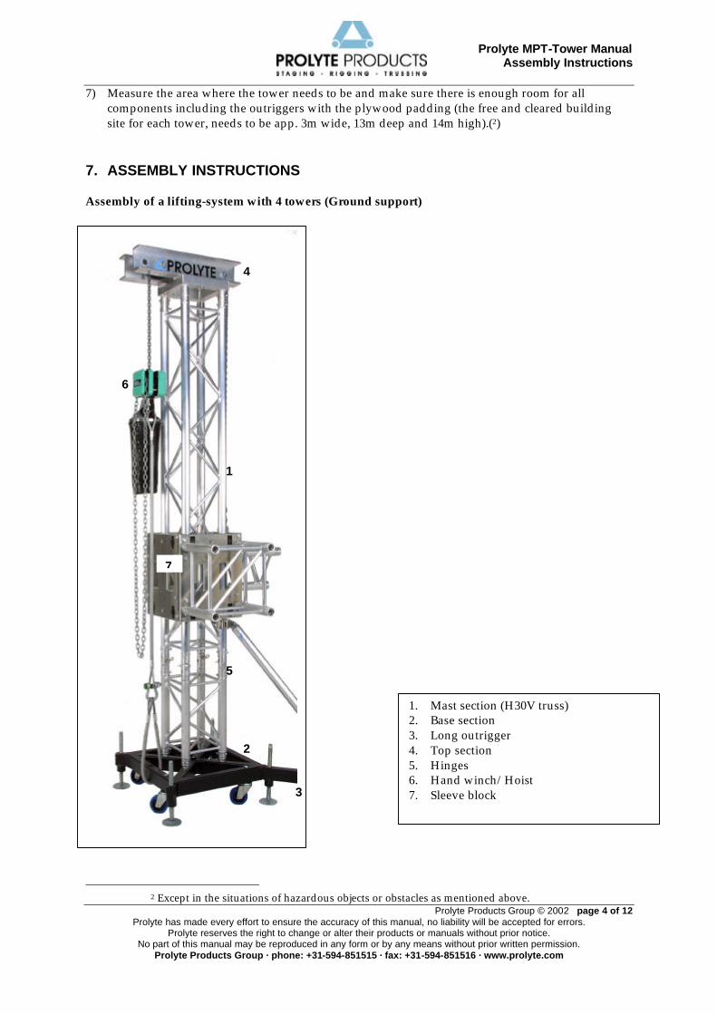
7. ASSEMBLY INSTRUCTIONS Assembly of a lifting-system with 4 towers (Ground support)
2 Except in the situations of hazardous objects or obstacles as mentioned above.
1. Mast section (H30V truss) 2. Base section 3. Long outrigger 4. Top section 5. Hinges 6. Hand winch/Hoist 7. Sleeve block
2
1
3
4
7
5
6
Prolyte MPT-Tower Manual Assembly Instructions
Prolyte Products Group © 2002 page 5 of 12 Prolyte has made every effort to ensure the accuracy of this manual, no liability will be accepted for errors.
Prolyte reserves the right to change or alter their products or manuals without prior notice. No part of this manual may be reproduced in any form or by any means without prior written permission.
Prolyte Products Group · phone: +31-594-851515 · fax: +31-594-851516 · www.prolyte.com
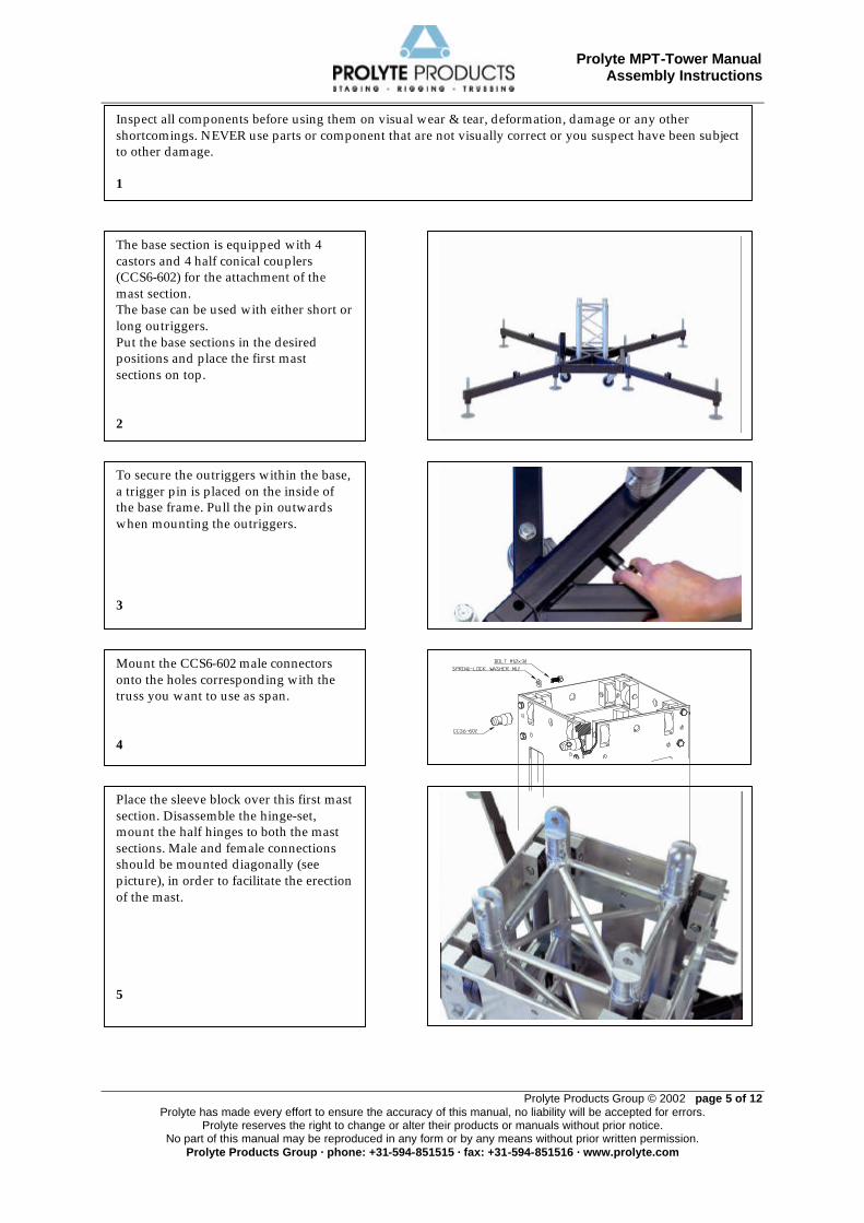
The base section is equipped with 4 castors and 4 half conical couplers (CCS6-602) for the attachment of the mast section. The base can be used with either short or long outriggers. Put the base sections in the desired positions and place the first mast sections on top. 2
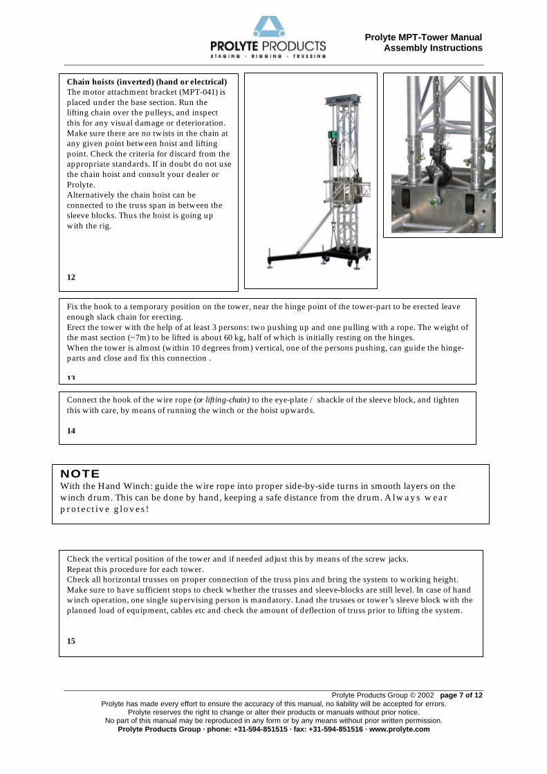
Mount the CCS6-602 male connectors onto the holes corresponding with the truss you want to use as span. 4
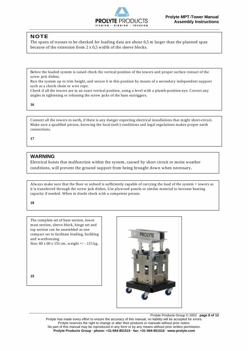
Place the sleeve block over this first mast section. Disassemble the hinge-set, mount the half hinges to both the mast sections. Male and female connections should be mounted diagonally (see picture), in order to facilitate the erection of the mast. 5
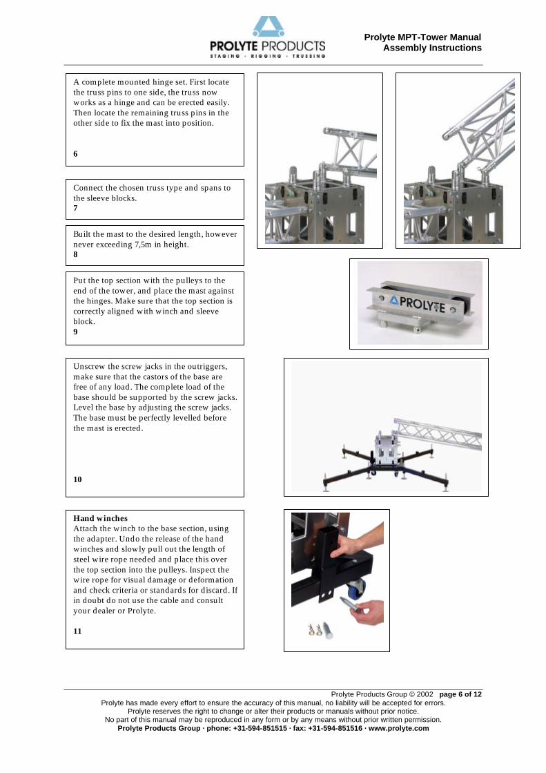
To secure the outriggers within the base, a trigger pin is placed on the inside of the base frame. Pull the pin outwards when mounting the outriggers. 3
Inspect all components before using them on visual wear & tear, deformation, damage or any other shortcomings. NEVER use parts or component that are not visually correct or you suspect have been subject to other damage. 1
Prolyte MPT-Tower Manual Assembly Instructions
Prolyte Products Group © 2002 page 6 of 12 Prolyte has made every effort to ensure the accuracy of this manual, no liability will be accepted for errors.
Prolyte reserves the right to change or alter their products or manuals without prior notice. No part of this manual may be reproduced in any form or by any means without prior written permission.
Prolyte Products Group · phone: +31-594-851515 · fax: +31-594-851516 · www.prolyte.com
A complete mounted hinge set. First locate the truss pins to one side, the truss now works as a hinge and can be erected easily. Then locate the remaining truss pins in the other side to fix the mast into position. 6
Connect the chosen truss type and spans to the sleeve blocks. 7
Built the mast to the desired length, however never exceeding 7,5m in height. 8
Put the top section with the pulleys to the end of the tower, and place the mast against the hinges. Make sure that the top section is correctly aligned with winch and sleeve block. 9
Unscrew the screw jacks in the outriggers, make sure that the castors of the base are free of any load. The complete load of the base should be supported by the screw jacks. Level the base by adjusting the screw jacks. The base must be perfectly levelled before the mast is erected. 10
Hand winches Attach the winch to the base section, using the adapter. Undo the release of the hand winches and slowly pull out the length of steel wire rope needed and place this over the top section into the pulleys. Inspect the wire rope for visual damage or deformation and check criteria or standards for discard. If in doubt do not use the cable and consult your dealer or Prolyte. 11
Prolyte MPT-Tower Manual Assembly Instructions
Prolyte Products Group © 2002 page 7 of 12 Prolyte has made every effort to ensure the accuracy of this manual, no liability will be accepted for errors.
Prolyte reserves the right to change or alter their products or manuals without prior notice. No part of this manual may be reproduced in any form or by any means without prior written permission.
Prolyte Products Group · phone: +31-594-851515 · fax: +31-594-851516 · www.prolyte.com
NOTE With the Hand Winch: guide the wire rope into proper side-by-side turns in smooth layers on the winch drum. This can be done by hand, keeping a safe distance from the drum. Always wear protective gloves!
Chain hoists (inverted) (hand or electrical) The motor attachment bracket (MPT-041) is placed under the base section. Run the lifting chain over the pulleys, and inspect this for any visual damage or deterioration. Make sure there are no twists in the chain at any given point between hoist and lifting point. Check the criteria for discard from the appropriate standards. If in doubt do not use the chain hoist and consult your dealer or Prolyte. Alternatively the chain hoist can be connected to the truss span in between the sleeve blocks. Thus the hoist is going up with the rig. 12
Fix the hook to a temporary position on the tower, near the hinge point of the tower-part to be erected leave enough slack chain for erecting. Erect the tower with the help of at least 3 persons: two pushing up and one pulling with a rope. The weight of the mast section (~7m) to be lifted is about 60 kg, half of which is initially resting on the hinges. When the tower is almost (within 10 degrees from) vertical, one of the persons pushing, can guide the hinge-parts and close and fix this connection . 13
Connect the hook of the wire rope (or lifting-chain) to the eye-plate / shackle of the sleeve block, and tighten this with care, by means of running the winch or the hoist upwards. 14
Check the vertical position of the tower and if needed adjust this by means of the screw jacks. Repeat this procedure for each tower. Check all horizontal trusses on proper connection of the truss pins and bring the system to working height. Make sure to have sufficient stops to check whether the trusses and sleeve-blocks are still level. In case of hand winch operation, one single supervising person is mandatory. Load the trusses or tower’s sleeve block with the planned load of equipment, cables etc and check the amount of deflection of truss prior to lifting the system. 15
Prolyte MPT-Tower Manual Assembly Instructions
Prolyte Products Group © 2002 page 8 of 12 Prolyte has made every effort to ensure the accuracy of this manual, no liability will be accepted for errors.
Prolyte reserves the right to change or alter their products or manuals without prior notice. No part of this manual may be reproduced in any form or by any means without prior written permission.
Prolyte Products Group · phone: +31-594-851515 · fax: +31-594-851516 · www.prolyte.com
The complete set of base section, lower mast section, sleeve block, hinge set and top section can be assembled as one compact set to facilitate loading, building and warehousing. Size: 60 x 60 x 155 cm, weight +/- 115 kg. 19
Always make sure that the floor or subsoil is sufficiently capable of carrying the load of the system + towers as it is transferred through the screw jack dishes. Use plywood panels or similar material to increase bearing capacity if needed. When in doubt check with a competent person. 18
NOTE The spans of trusses to be checked for loading data are about 0,5 m larger than the planned span because of the extension from 2 x 0,5 width of the sleeve blocks.
WARNING Electrical hoists that malfunction within the system, caused by short circuit or moist weather conditions, will prevent the ground support from being brought down when necessary.
Before the loaded system is raised check the vertical position of the towers and proper surface contact of the screw jack dishes. Run the system up to trim height, and secure it in this position by means of a secondary independent support such as a clutch chain or wire rope. Check if all the towers are in an exact vertical position, using a level with a plumb-position-eye. Correct any angles in tightening or releasing the screw jacks of the base outriggers. 16
Connect all the towers to earth, if there is any danger expecting electrical installations that might short-circuit. Make sure a qualified person, knowing the local (soil-) conditions and legal regulations makes proper earth connections. 17
Prolyte MPT-Tower Manual Assembly Instructions
Prolyte Products Group © 2002 page 9 of 12 Prolyte has made every effort to ensure the accuracy of this manual, no liability will be accepted for errors.
Prolyte reserves the right to change or alter their products or manuals without prior notice. No part of this manual may be reproduced in any form or by any means without prior written permission.
Prolyte Products Group · phone: +31-594-851515 · fax: +31-594-851516 · www.prolyte.com
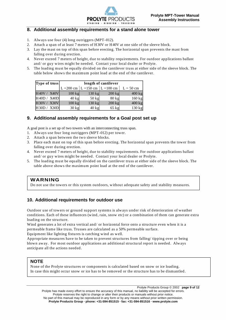
8. Additional assembly requirements for a stand alone tower 1. Always use four (4) long outriggers (MPT–012). 2. Attach a span of at least 7 meters of H30V or H40V at one side of the sleeve block. 3. Lay the mast on top of this span before erecting. The horizontal span prevents the mast from
falling over during erection. 4. Never exceed 7 meters of height, due to stability requirements. For outdoor applications ballast
and/or guy wires might be needed. Contact your local dealer or Prolyte. 5. The loading must be equally divided on the cantilever truss at either side of the sleeve block. The
table below shows the maximum point load at the end of the cantilever.
Type of truss length of cantilever L =200 cm L =150 cm L =100 cm L = 50 cm H40V / X40V 100 kg 130 kg 200 kg 400 kgH40D / X40D 40 kg 50 kg 80 kg 160 kgH30V / X30V 100 kg 130 kg 200 kg 400 kgH30D / X30D 30 kg 40 kg 65 kg 130 kg
9. Additional assembly requirements for a Goal post set up A goal post is a set up of two towers with an interconnecting truss span. 1. Always use four long outriggers (MPT–012) per tower. 2. Attach a span between the two sleeve blocks. 3. Place each mast on top of this span before erecting. The horizontal span prevents the tower from
falling over during erection. 4. Never exceed 7 meters of height, due to stability requirements. For outdoor applications ballast
and/or guy wires might be needed. Contact your local dealer or Prolyte. 5. The loading must be equally divided on the cantilever truss at either side of the sleeve block. The
table above shows the maximum point load at the end of the cantilever. 10. Additional requirements for outdoor use Outdoor use of towers or ground support systems is always under risk of deterioration of weather conditions. Each of these influences (wind, rain, snow etc) or a combination of them can generate extra loading on the structure. Wind generates a lot of extra vertical and/or horizontal force onto a structure even when it is a permeable frame like truss. Trusses are calculated as a 50% permeable surface. Equipment like lighting fixtures is catching wind as well. Appropriate measures have to be taken to prevent structures from falling/tipping over or being blown away. For most outdoor applications an additional structural report is needed. Always anticipate all the actions needed.
WARNING Do not use the towers or this system outdoors, without adequate safety and stability measures.
NOTE None of the Prolyte structures or components is calculated based on snow or ice loading. In case this might occur snow or ice has to be removed or the structure has to be dismantled.
Prolyte MPT-Tower Manual Assembly Instructions
Prolyte Products Group © 2002 page 10 of 12 Prolyte has made every effort to ensure the accuracy of this manual, no liability will be accepted for errors.
Prolyte reserves the right to change or alter their products or manuals without prior notice. No part of this manual may be reproduced in any form or by any means without prior written permission.
Prolyte Products Group · phone: +31-594-851515 · fax: +31-594-851516 · www.prolyte.com
1. Check the building site for any obstacles that might influence the structure or its building. 2. Make sure that the system is built on solid ground. In situations where it has to be built on grass,
sand or any unstable subsoil, under fill the screw jacks with plywood pads of 300x300x20mm (minimum size for each screw jack), and preferably a larger one (1200 x1200x20mm) under these, thus combining all the inner base screw jacks.
3. Follow the assembly instructions from chapter 7 up to point 20. 4. Before lifting the structure to working height apply ballast first. Ballast/counterweights can be
composed of various elements, depending on the national or local building codes and regulations, and the economic availability of materials. Check this with your local building inspection authorities and/or a local structural engineer.
- Water tanks connected to the tower base - Interconnected stage floor structure, only if this is a completely rigid such as in a
scaffolding frame. If connected by at least 4 scaffolding clamps to each lower mast section, the weight of the stage might be taken as part of the counterweight or ballast.
- Lighting or sound equipment - Ground anchors - Concrete blocks - Canvas bags filled with sand or rubble - Steel bars
5. Ballast has to be attached directly to each base section. The best way to do this is to place the
ballast on the long outriggers.
11. Spare parts Spare Parts: Base-section MPT-004 SP-004-CAS Blue, swivel castor Outriggers SP-SPIN-MPT Screw jack + dish ACC-LP-10 Locking pin CCS7-705 R-Spring for locking pin Hinge-set 4xCCS6-H CCS6-H-M-135 Male (pin) hinge part CCS6-H-FM-45 Female (fork) hinge part ACC-LP-16 Locking pin for hinge CCS7-705 Safety R spring Hand winch MPT-014 SW-08-1500HOE Steel wire with hook SP-CRANCK Crank SP-CRANCK BOLT Wingnut for crank ACC-LP-020 Locking pin for winch stand CCS7-705 Safety R spring
WARNING Neglecting the addition of the appropriate amount of ballast and/or not applying part of the guy wires is dangerous. Under influence of wind this can result in failure of the complete structure.
WARNING: NOT FOLLOWING THE GUIDELINES IN THIS MANUAL MAY CAUSE DANGER, PROPERTY
DAMAGE, INJURIES OR DEATH.
Prolyte MPT-Tower Manual Assembly Instructions
Prolyte Products Group © 2002 page 11 of 12 Prolyte has made every effort to ensure the accuracy of this manual, no liability will be accepted for errors.
Prolyte reserves the right to change or alter their products or manuals without prior notice. No part of this manual may be reproduced in any form or by any means without prior written permission.
Prolyte Products Group · phone: +31-594-851515 · fax: +31-594-851516 · www.prolyte.com
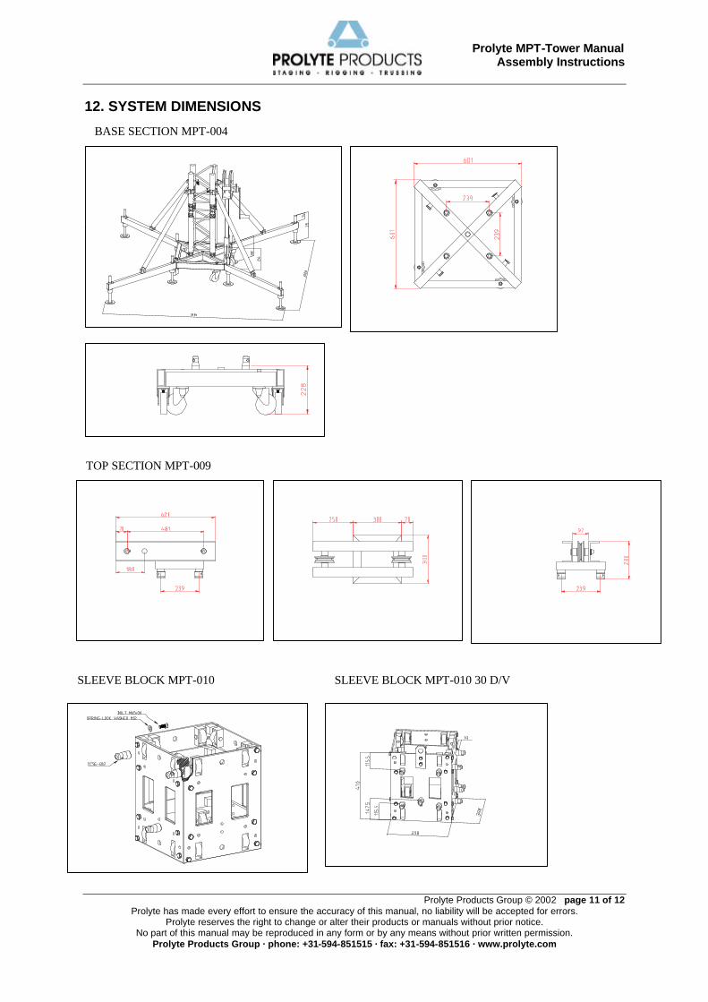
12. SYSTEM DIMENSIONS V
BASE SECTION MPT-004
TOP SECTION MPT-009
SLEEVE BLOCK MPT-010 SLEEVE BLOCK MPT-010 30 D/V
Prolyte MPT-Tower Manual Assembly Instructions
Prolyte Products Group © 2002 page 12 of 12 Prolyte has made every effort to ensure the accuracy of this manual, no liability will be accepted for errors.
Prolyte reserves the right to change or alter their products or manuals without prior notice. No part of this manual may be reproduced in any form or by any means without prior written permission.
Prolyte Products Group · phone: +31-594-851515 · fax: +31-594-851516 · www.prolyte.com
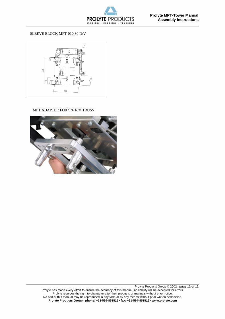
SLEEVE BLOCK MPT-010 30 D/V
MPT ADAPTER FOR S36 R/V TRUSS