proof of a composite repair concept for aeronautical
TRANSCRIPT

HAL Id: hal-02909687https://hal.archives-ouvertes.fr/hal-02909687
Submitted on 30 Jul 2020
HAL is a multi-disciplinary open accessarchive for the deposit and dissemination of sci-entific research documents, whether they are pub-lished or not. The documents may come fromteaching and research institutions in France orabroad, or from public or private research centers.
L’archive ouverte pluridisciplinaire HAL, estdestinée au dépôt et à la diffusion de documentsscientifiques de niveau recherche, publiés ou non,émanant des établissements d’enseignement et derecherche français ou étrangers, des laboratoirespublics ou privés.
Proof of a composite repair concept for aeronauticalstructures: a simplified method
Francis Collombet, Yves Davila, Sergio Avila, Alexander Morales, LaurentCrouzeix, Yves-Henri Grunevald, Hilario Hernandez, Nathalie Rocher,
François Cénac
To cite this version:Francis Collombet, Yves Davila, Sergio Avila, Alexander Morales, Laurent Crouzeix, et al.. Proof ofa composite repair concept for aeronautical structures: a simplified method. Mechanics & Industry,EDP Sciences, 2019, 20 (8), pp.812. �10.1051/meca/2020056�. �hal-02909687�

Mechanics & Industry 20, 812 (2019)© AFM, EDP Sciences 2020https://doi.org/10.1051/meca/2020056
Mechanics&IndustryAvailable online at:
www.mechanics-industry.org
Selected scientific topics in recent applied engineering – 20 Years of the ‘French Associationof Mechanics – AFM’REGULAR ARTICLE
Proof of a composite repair concept for aeronautical structures:a simplified methodFrancis Collombet1,*, Yves Davila1, Sergio Avila2, Alexander Morales2, Laurent Crouzeix1, Yves-Henri Grunevald3,Hilario Hernandez2, Nathalie Rocher1, and François Cénac4
1 Université de Toulouse, UPS, INSA, Mines d’Albi, ISAE, ICA (Institut Clément Ader). Espace Clément Ader,3 rue Caroline Aigle,31400 Toulouse, France
2 Instituto Politecnico Nacional, ESIME Ticoman. Av. Ticoman N° 600, 07340 Ciudad de Mexico, Mexico3 Composites, Expertise & Solutions. 131 Traverse de La Penne aux Camoins, 13821 La Penne-Sur-Huveaune, France4 Bayab Industries, 10 allée de Longueterre, 31850 Montrabé, France
* e-mail:
Received: 7 October 2019 / Accepted: 16 June 2020
Abstract.This paper provides an illustration of all stages of primary aeronautical composite structure repair byusing industrial tools and scientificmethodologies, as well as numerical tools to simplify the cross-over analysis ofthe mechanical behaviour of the repaired area. Economically and scientifically speaking, one of the mainchallenges of composite repair (for monolithic long fiber composite parts) consists of promoting a bondedcomposite patch option without additional riveted doublers. To address this challenge, size reduction of thepatch could be mandatory. A patent (jointly owned by ICA, Bayab Industries and CES), entitled “Method forrepairing a wall consisting of a plurality of layers”, is devoted to reducing repair patch dimensions of monolithiccomposite parts provided the bonding zone has a stepped-lap geometry. This patent is based on a simple ideathat no overlapping length is required between composite plies for load transfer except in the fiber directions ofthe plies (unidirectional or biaxial long fiber reinforcements with epoxy matrix). To prove this concept, weconsider on one hand, a situation unusual in the literature by studying a composite specimen without fibersaligned along the main loading axis, and on the other hand, a classical situation of where the shape of thespecimen is adapted to be studied by uniaxial tension tests. After different manufacturing steps, the studiedspecimen contains three zones representing both the influence of the total thickness of a repair patch, thestepped-lap area assembled with an adhesive film and the parent composite part. Basically, a simple parentstructure consisting of 16 plies of UDHexply
®
M21/35%/268/T700GC (close to Airbus composite rawmaterialson board in A380) is manufactured with a stacking sequence of [+45/−45/−45/+45/+45/−45/−45/+45]s.Then, the parent structure is machined by the Airbus Abrasive Water Jet machine and the final repair area hasa stepped-lap geometry by overlapping successive plies of the same nature as the parent plate and after havingpreviously applied an adhesive film (cured at 180 °C). Furthermore, 3 values of overlap length (respectively, 6, 8and 13mm) are investigated to include the mean value required by Airbus in the case of the use of the studiedprepreg. After abrasive water jet machining of the composite parent part, repair patch manufacturing wasperformed according to Airbus requirements. The studied specimens were cut from the final plate (involving theparent plate, the stepped lap zone and the zone of the patch itself) and tested in an uniaxial tensile configurationwith a loading direction shifted 45° with respect to the fiber direction. Furthermore, studying uniaxial tensiletests on multilayer-pasted interface is innovative in the literature. In this paper, it is shown that the stepped-laparea assembled with an adhesive film is not the weak link of the mechanical response but rather the parent area,i.e. the unrepaired monolithic composite. Numerical calculations confirm this proof of concept by underlyingthat the level of shear stress in the adhesive film, for these three overlapping values, is below the chosen limitvalue. These results show that the patch size reduction is possible.
Keywords: Composite repair / abrasive water jet machining / composite bonded assembly / light finiteelements modelling / mechanical testing

Fig. 1. View of the repair evaluator with (a) the start and (b) the last phase of the multiaxial mechanical test, see [5] for details.
2 F. Collombet et al.: Mechanics & Industry 20, 812 (2019)
1 Introduction
This paper deals with scientific and technical issues relatedto the repair of aeronautical structures, made of multilayermonolithic long fibre composites. There is an increasingneed for such repairs due to the entry into service ofhundreds of B787 and A350 aircraft per year. In the repairprocess, according to the customer services of the aircraftmanufacturers, one of the issues is to limit the influence ofthe area and/or the volume of removal of material andreduce the prohibitive time of immobilization of theaircraft (which costs the operating company roughly 100–200 kUS dollars per day).
According to this Specification of Work (SoW),a joint patent [1] held by the Clement Ader Institute,the two SMEs Composites Expertise & Solutions andBayab Industries, is of interest because it is based ona simple idea that a nominal overlapping length is onlynecessary in the direction of each UD ply. This patentallows the description and modelling of a minimumvolume of material to be removed while ensuringa nominal transfer of efficient stress flow between theparent composite part and the repair patch. To give someorders of magnitude, it was shown that this approach canlead to the reduction of the repair patch grip by morethan 70% [2], making the adhesive patch certifiable byaeronautic regulation authorities [3]. Actually today, thebonding repair patch is allowed alone (i.e. withoutadditional riveted doublers [4]) only if its loss is not animpediment to the limit loading transfer (“patch-off”concept). In aeronautics [3], all critical structures willhave a repair size limit no larger than a size that allowsLimit Load strength to be achieved with the repair failedor failed within constraints of the arresting designfeatures (in the repair or base structure). This approachis needed to ensure Limit Load capability in the event ofbonded repair failures.
Two geometries for bonding composite repair patch areused in aeronautic industry with respectively tapered scarfand stepped-lap joints. During thirty years, Boeingemployed only scarf geometry to repair composite primaryaeronautic structures. Airbus was the first to introduce thestepped-lap geometry for composite repair. As regards
the overlapping length, Airbus was more conservative thanBoeing. For example, Airbus requires 8mm overlap for0.13mm ply thickness while Boeing 5mm overlap for thesame ply thickness. We have chosen stepped-lap geometryfor taking the best performance in terms of patch sizereduction [2].
To be close to industrial applications, an originalmethodology of mechanical characterization (called Multi-Instrumented Technological Evaluator tool box) has beenproposed [2,5]. The MITE tool box allows the design ofcase-by-case specific repair evaluators that can be tested ina multi-axial testing machine under complex loadingsequences. For achieving such approach, metric compositeparts are mandatory according to the real patch repair sizeand the definition of the SoW because of the case-by-casenature of the composite repair issues. The proof of theinterest of the joint patent has been done in the past thanksto the Multi-Instrumented Technological Evaluator toolbox [5], cf. Figure 1.
The originality of the current paper lies in the choice ofa composite specimen (i.e. a composite part with a simplergeometry compared to a composite repair evaluator but inthe framework of an unusual situation because thisspecimen will be tested without fiber directions in themain loading axis using a classical tension set-up (cf.Fig. 2). Furthermore, whatever the chosen stackingsequence, studying uniaxial traction tests on multilayer-stepped interface is innovative in the literature.
On Figure 2, only the half thickness is shown forclarity. On Figure 2a, the stacking sequence is quasi-isotropic and frequent in the world of composites and inaeronautics. The performance of our approach for such astacking sequence has been demonstrated on the techno-logical evaluator, and works. Most of the loading flow goesthrough the plies at 0° and therefore the associated bondedassemblies. The ruptures of the part and the bond occur atthe same time (because of the plies at 0°). It is thereforedifficult to know if the bond has been damaged due to thepart rupture or vice versa. Furthermore, a tension set-upwith an adequate loading capacity is not easily availablefor such stacking sequences. On Figure 2b, an unusualstacking sequence is shown, only used for demonstration.It has no industrial utility, except for a torsion shaft, but

Fig. 2. Illustration of two situations of composite specimens with stepped lap respectively with, (a) classical stacking sequence and(b) unusual stacking sequence (scheme of loading transfer and its intensity under tension indicated by the white arrows with respect totheir size and direction).
F. Collombet et al.: Mechanics & Industry 20, 812 (2019) 3
it allows verification that the bonded area is not the weaklink in the system using a classical tension set-up.
To illustrate our purpose, we have chosen to studya parent plate consisting of 16 plies of UD Hexply
®
M21/35%/268/T700GCprepreg cured in autoclave at 180 °C, forthis first stage, with a stacking sequence: [+45°/−45°/−45°/+45°/+45°/−45°/−45°/+45°/+45°/−45°/−45°/+45°/+45°/ −45°/−45°/+45°] i.e. [((+45°/−45°)s)s]s.
The second stage of this study corresponds toa machining phase using an abrasive water jet techniquefor the composite milling. This phase was performed withthe mobile machine called REPLY.5, designed by theinnovative small company Bayab Industries. It is the onlymachine certified by Airbus to repair primary structures onthe A350 [6].
The third phase concerns the lay-up of the stepped-lapwith the same material after having previously stacked anadhesive film. The total length of the UD is sufficient toprovide a final plate with the composite bonding assemblyzone located far away from its extremities (grip zonesduring the test). The fourth phase is devoted to thepolymerization of the adhesive film and the addedcomposite plies. The patch zone and the added monolithiczone polymerization is performed using the portable hotbonder Aeroform AHB-380, to be in accordance with the insitu Airbus repair requirements [6]. Different overlaplengths (6, 8 and 13mm) are considered to surround theoverlapping value recommended in aeronautics by provid-ing a step ratio of about 1/30. Indeed, the overlappingdistance is expressed as a ratio of the ply thickness, and, inaeronautical applications, this ratio is usually 30 (which isroughly the ratio between 8mm overlap length and0.26mm ply thickness), whatever the fibre orientationwith respect to the main loading direction.
The fourth phase is devoted to cut test coupons fromparent plates with these three overlap ratios, 20, 30 and 50respectively, to perform uniaxial tests. As was explainedpreviously, this situation is unusual but represents a goodcomprise between a simple manner to test (uniaxialtension) and the material orientation to study if a nominaloverlap length is strictly necessary in the direction of theUD fibres.
In a fifth phase, a finite element study was performed inparallel with the experimental investigation. The repairzone was modelled through an innovative multi-scale
method [7] in which the composite substrates are modelledthrough shell elements and the adhesive joint consists ofvolume elements. The aim is to avoid the use of overlyheavy finite element calculations such as described in [8], asthis penalizes the design of large repaired structures,making cross-test calculations very time-consuming. Thenumerical model shows that the non-repair zone is the weaklink of these coupons and not the overlapped region. Thesenumerical results confirm the experimental observationsduring tension tests.
2 Manufacturing and abrasive water jetmachining process
The first stage of this study corresponds to the fabricationand machining process of a monolithic carbon-epoxycomposite plate. For this study a 16 ply composite plateof [((+45°/−45°)s)s]s was made from a UD Hexply
®
M21/35%/268/T700GC prepreg, cured in autoclave at 180 °C.Afterwards the plate is cured and then machined. Threestep ratios (step length over ply thickness) were studied,20, 30 and 50, which roughly correspond to overlap lengthsof 6mm, 8mm and 13mm respectively. The machining isdone using the abrasive water jet (AWJ) removaltechnique. The AWJ blind machining was performed bya mobile machine (REPLY.5, cf. Fig. 3).
AWJ is the only technique allowing an offset machining“layer by layer” of multi-layered composite material (to becapable to take into account the variability of thecomposite part [9]). This is very difficult with the cuttingtools used by the conventional techniques [10].
The REPLY.5 AWJmachine consists of three principalelements, the control unit which contains the pump and thecontrol system (cf. Fig. 3a), the abrasive water jetequipment (which is light −50 kg − compared to thecompeting project attempts) and the control panel tooperate the machine (cf. Fig. 3b).
After fixing the composite plate onto the workbench,the AWJmachine is placed on top of it and is maintained inposition with suction cups (cf. Fig. 4a). In an industrialsituation, this suction system allows the positioning of themachine onto a composite fuselage. The machine isthen levelled to roughly adjust the distance between theAWJ head (nozzle) and the composite part (cf. Fig. 4b).

Fig. 4. Abrasive water jet machine Reply.5 with (a) levelled machine and (b) nozzle.
Fig. 3. Bayab Industries abrasive water jet machine REPLY.5 with (a) control unit and (b) abrasive water jet equipment (50 kg) andcontrol panel.
Fig. 5. Alignment process of the nozzle over the x- and y-maindirections of the composite plate.
4 F. Collombet et al.: Mechanics & Industry 20, 812 (2019)
The waste generated during the machining process(composed by composite dust, abrasive particles andwater) is removed by a patented aspirator system.
The machine is aligned by a laser level to the markedalong the x- and y-main directions of the studied parentcomposite plate (cf. Fig. 5).
After aligning the machine, the layer of compositematerial corresponding to the first step (here ply #16) isremoved. As an illustration, the first machined step forthe step lap ratio of 20 is presented in Figure 6. For theother step lap ratios of 30 and 50, the same procedure isapplied. The cut trajectory and cut parameters (water jetpressure, and nozzle feed rate) are programmed into themachine. These parameters are Intellectual Propertyof Airbus and Bayab Industries and have not beendisclosed.
Once the machining process in one ply is finished,a verification is done by means of image analysis using thecamera installed on the AWJ machine and a lighting of themachined zone through a set of four low-angled lightsaimed in the four possible orientations of the reinforcementrespectively, 0°, 90°, +45° and −45° (cf. Fig. 7a). To verifythe fibre direction of the ply below, the camera takes fourdifferent images using each lighting angle. Indeed, the
lightning emitted by the low-angled light is diffracteddifferently depending on the angle with respect to the longfibre orientation. The control unit compares the recordedimages pixel-by-pixel. For accurate information, a selectionof images from the screen of the control panel (cf. Fig. 7b)

Fig. 6. View through the protection screen of themachine duringthe machining of the step#1 for the stepped lap ratio of 1:20 (steplength over ply thickness).
Fig. 7. Verification process of the machining surface with (a) ovselection of the images on the control panel to estimate the locationspots due to no light diffraction).
Fig. 8. Machining of the 15 steps (for 16 plies in total) with (a) schemstepped-lap for the overlap ratio of 20.
F. Collombet et al.: Mechanics & Industry 20, 812 (2019) 5
shows an estimation of the matrix ratio (percentage of darkspots thanks to no light diffraction, ≈60% according to plythickness variabilities, [9]) in an interface between twoplies. The matrix ratio is evaluated to ensure that just oneply was removed. This is an alternative to directmeasurement of the cut depth.
Afterward, the process or nozzle alignment, machiningand verification are repeated. As an illustration, theresulting stepped lap profile (step ratio of 20) is shown inFigure 8.
3 Repair process
After completion of the machining process, the compositeplates are cut in halves in order to create the possibility ofrepairing two sets of plates for each overlap ratio (cf.Fig. 8). This situation is representative of a “through hole”repair. We label the parent plate as “Plate 13”, correspond-ing to a step length of 13mm or a step ratio of 50, as shownin Figure 9 and hereafter as an illustration in this paper.Typical Airbus repairs require that the material of therepair patch should be cured at 120 °C, in order to not
erlap zone analysed by image analysis and (b) visualization andof the interface between to plies (i.e. presence of numerous dark
e of milled profile (not to scale) and (b) view of the finishedmilled
6 F. Collombet et al.: Mechanics & Industry 20, 812 (2019)
thermally degrade the material of the parent structure,which was cured at 180 °C, if applying a certain number ofcure cycles of the repair patch. However, in the repairspresented here, in order to limit the influence of thedifferent materials in the final tested structure, the chosenrepair material of the reconstituted zone is the same one asthat of the parent plate, i.e. Hexply
®
M21/35%/268/T700GC and the adhesive film was cured at 180 °C as well.However, to be close to the Airbus repair processrequirements, the curing process for the parent plate isperformed with a portable hot bonder machine under onlyvacuum instead of being placed in an autoclave [6].
Fig. 9. View of parent composite plate noted “Plate 13” (overlaplength of 13mm), shown after AWJ milling phase and before therepair patch installation.
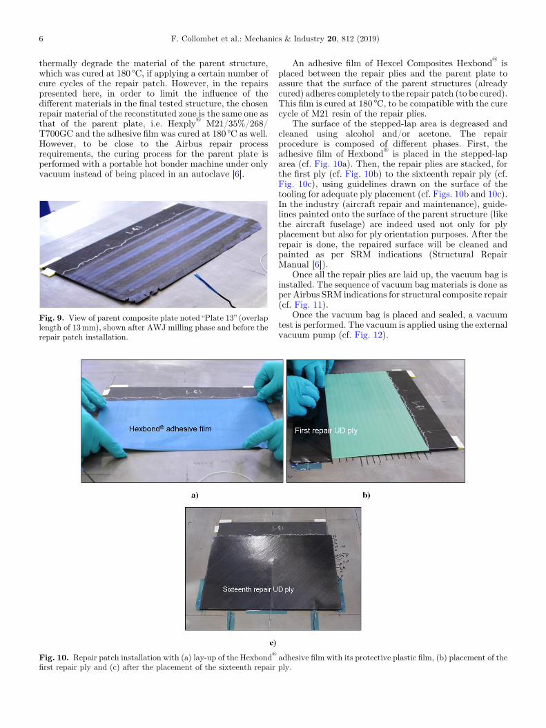
Fig. 10. Repair patch installation with (a) lay-up of the Hexbond®
first repair ply and (c) after the placement of the sixteenth repair
An adhesive film of Hexcel Composites Hexbond®
isplaced between the repair plies and the parent plate toassure that the surface of the parent structures (alreadycured) adheres completely to the repair patch (to be cured).This film is cured at 180 °C, to be compatible with the curecycle of M21 resin of the repair plies.
The surface of the stepped-lap area is degreased andcleaned using alcohol and/or acetone. The repairprocedure is composed of different phases. First, theadhesive film of Hexbond
®
is placed in the stepped-laparea (cf. Fig. 10a). Then, the repair plies are stacked, forthe first ply (cf. Fig. 10b) to the sixteenth repair ply (cf.Fig. 10c), using guidelines drawn on the surface of thetooling for adequate ply placement (cf. Figs. 10b and 10c).In the industry (aircraft repair and maintenance), guide-lines painted onto the surface of the parent structure (likethe aircraft fuselage) are indeed used not only for plyplacement but also for ply orientation purposes. After therepair is done, the repaired surface will be cleaned andpainted as per SRM indications (Structural RepairManual [6]).
Once all the repair plies are laid up, the vacuum bag isinstalled. The sequence of vacuum bag materials is done asper Airbus SRM indications for structural composite repair(cf. Fig. 11).
Once the vacuum bag is placed and sealed, a vacuumtest is performed. The vacuum is applied using the externalvacuum pump (cf. Fig. 12).
adhesive film with its protective plastic film, (b) placement of theply.

Fig. 11. Scheme of the vacuum bag products (not to scale) for the composite patch curing by heating blanket (according to SRMA350chapter 51.77.11, see [6]).
Fig. 12. Overview of the vacuum bag products and theconnections to the different thermocouples.
Fig. 13. Portable hot bonder Aeroform AHB-380 (right) and theportable vacuum pomp (left).
Fig. 14. View of finished repair on “Plate 13” after curing(overlap length of 13mm).
F. Collombet et al.: Mechanics & Industry 20, 812 (2019) 7
The temperature cycle is programed into the hotbonder (cf. Fig. 13). The M21 resin cures at 180 °C for 2 h.An intermediate dwell at 100 °C for 30min is used in orderto homogenise the temperature in the unconsolidatedpatch prepreg and to promote the movement of resin and
removal of entrapped air causing porosities in the material.The temperature ramps are set at 3 °Cmin−1. The vacuumis applied with an external portable vacuum pump (cf.Fig. 13).
When the curing cycle is complete, the part isdemoulded. The resulting part is shown in Figure 14.Finally, coupons for tensile test are cut from the repairedparent plate using an abrasive water jet machine. Thecentral zone is only considered to eliminate defects in theboundary of the parent plate.
4 Light finite element models and mechanicaltests
A light finite element (FE) modelling strategy is used [5,7].This strategy uses shell elements for the compositelaminate and volume elements for the adhesive joint (cf.Fig. 15). Themesh of the composite parent zone ismodelledwith shell elements of 0.44� 0.44mm dimensions. Onevolume element of 0.1mm thick with the same width andlength as the composite shell elements is employed tomodelthe adhesive film with a thickness to length ratio of 1:4.

8 F. Collombet et al.: Mechanics & Industry 20, 812 (2019)
To ensure a continuous transfer of stresses and nodaldisplacements, each segment of the step repair is linked tothe previous one using rigid beam elements. In ourapplications, there was no adhesive rupture but onlya cohesive one, if any. Thus, since we are not interested instudying the interface failure of the adhesive joint (noadhesive rupture) and with the need to have a light FEmodel, cohesive elements are not considered. This lightmodelling strategy allows the reduction in computationtime and facilitates the experiment/calculation compar-isons. The initial implementation of this methodology wasprogrammed in SamcefTM code [5,7] and it was successfullyapplied in the AbaqusTM code. Details of the number ofelements and the degrees of freedom for each of the 6, 8 and13mm overlapping length models are given in Table 1.
The shape of the tensile repaired coupon is shown inFigure 16. The repaired coupon is 22mm wide in the gaugezone, corresponding to the overlap zone. Its end tabs are30mm wide in order to avoid a possible material failure atthe machine clamps. The zone of 20mm length approxi-mately located between the overlap and the tab isconsidered as representative of a non-repaired area. Thiszone corresponding to the non-repaired zone of the parent
Fig. 15. Mesh detail between two consecutive steps (ply #n and#n-1).
Fig. 16. 3D representation of the FEmodel (shell thicknesses rendeview (XY plane).
zone has the original parent plate of 16 plies, while thereconstituted material in the patch area has one extra ply(repair ply #0) with the same orientation as the repair ply#1. This filler ply is only used to ensure continuity of thebottom surface of the repair, and to provide support for thestacked plies, otherwise there would be ply waviness in therest of the stack. Thus, this zone has a stacking sequencewith 17 plies in total in accordance with composite repairimplementation (cf. Fig. 17). As in Figures 2 and 17 useswhite arrows to show the loading flow transfer principlefrom the parent plies to the repair plies.
In this study, we are not concerned by the ultimatetensile strength of the coupon, according to the aeronauti-cal specifications of work for which no damage is allowed(no defect event in general). The behaviour of the±45°tensile test is matrix dominated, and having the fibresoriented at an angle different from the loading direction,the resulting axial stress � strain curve begins nonlinearbecause of many reasons which have not been investigatedin this study, such as damage initiation in the matrix.We are interested to study the performance of therepair while the 16-ply monolithic non-repaired zone ofthe material is within its linear regime just before thenonlinear regime. The material behaviour of the FEmodels is considered as linear elastic without consideringnon-linearity. This is an arbitrary choice in order to applythe convenient Tsai-Hill (TH) criterion.
In the input material data, the priority characteristicsto be identified from the initial parent part are those mostinfluenced by the matrix behaviour i.e. the transverse
Table 1. Definition of the three meshes per overlap lengthvalue.
Step size (mm) 6 8 13
Number of Finite Elements 48 000 58 000 86 000DoF (AbaqusTM variables) 309 000 367 000 542 000
red at their given values) with (a) side view (XZ plane) and (b) top

Fig. 17. Scheme of composite repair overlap considerations (not to scale).
Fig. 18. Inverse identification of the material properties (at the beginning of the non-linear behaviour) using a tensile test onunrepaired specimens extracted from the manufactured mother plate.
F. Collombet et al.: Mechanics & Industry 20, 812 (2019) 9
Young’s moduli E2=E3 and the axial-transverse shearmoduli G12=G13 of the UD prepreg. We have identifiedthese two input material values. Indeed, there are someadjustments to be done compared to the values given bythemanufacturer due to the real state of the matrix (ageing…), the manufacturing conditions and the test configura-tion. This is achieved through an inverse method by a loopof optimisation reducing the gap by adjustments betweennumerical and experimental results in tension. For that,specimens are extracted from a non-repaired zone of the 16plies±45° plates. These testing coupons, noted “Ep 1”, “Ep2” and “Ep 3”, are shaped in the form of a dumbbell (withwider end tabs and a narrow gauge area) in order to controlthe place where the testing coupon is expected to reacha non-linear response (i.e. away from the clamps of the testmachine). The beginning of the nonlinear part of the axial
stress-strain curve (cf. Fig. 18) is used in the inverseanalysis leading to the elastic and our arbitrary or chosenlimit values of shear strength and transverse strengthmatrix identifications (in red on Tabs. 2 and 3). For theother mechanical properties, the values given by the makerare considered to be reliable (in black on Tabs. 2 and 3).
The material properties of the Hexply®
M21/35%/268/T700GC and the Hexbond
®
adhesive film are indicated inTable 2. The strength values used to calculate the Tsai-Hill(TH) criterion are indicated in Table 3. These values areentered into the FE model to compute the Tsai-Hillcriterion for the composite material as a high probability ofthe issue occurrence. As mentioned before, this test ismainly dominated by the shear and tensile matrixproperties, and it is well below the maximum load capacityof the fibres. The values for the tensile strength of

Table 2. Material properties of the Hexply®
M21/35%/268/T700GC (in red, the updated properties by inverseidentification along reinforcement orientation) and the Hexbond
®
adhesive film.
UD Ply: Hexply®
M21/35%/268/T700GC Adhesive film: Hexbond®
Property Value Property Value
Axial Young’s modulusE1 (MPa)
140 500 Adhesive Young’s modulusEa (MPa)
3 800
Transverse Young’s modulusE2, E3 (MPa)
10 100 Adhesive Poisson’s rationa
0.300
Axial-transverse Poisson’s ration12, n13
0.334 Mean adhesive thicknessta (mm)
0.100
Transverse-transverse Poisson’s ration23
0.171
Axial-transverse shear modulusG12, G13 (MPa)
4600
Transverse-transverse shear modulusG23 (MPa)
3600
Mean ply thicknesstply (mm)
0.260
Table 3. Strength of the polymerised ply (in red the limit values obtained by inverse identification along thereinforcement orientation) of the Hexply
®
M21/35%/268/T700GC and the Hexbond®
adhesive film.
Property Value Property Value Property Value
Axial tensile strengthXT (MPa)
2 800 Transverse tensile strengthYT (MPa)
20 Shear strengthS (MPa)
23
Axial compressive strengthXC (MPa)
−1 700 Transverse compressivestrength YC (MPa)
−300
Average adhesive shear strengthin the overlap (MPa)
35 Adhesive tensile strength(MPa)
70 Adhesive peelstrength (MPa)
20
10 F. Collombet et al.: Mechanics & Industry 20, 812 (2019)
the matrix (YT) and the shear strength (S) are belowthe typical epoxy values, as these values were identified todetermine the limit values on the±45° test configuration.A Mixed Failure criterion developed by [7] is used for theadhesive film. This criterion is based on the work of [11] and[12]. The input data are presented in Table 2.
Three different models are considered, one for each ofthe overlap lengths respectively, 6mm, 8mm and 13mm.
Fig. 19. Axial tensile test configuration with, (a) set-up with twocameras for 3D DIC and (b) zoom of the repaired coupon with itsDIC speckle (in white).
5 Test calculation comparisons
Three coupons per overlap length were tested in a universaltest machine. Here we illustrate with results concerning the13mm overlap repair length for the three specimens noted“Ep 13–1”, “Ep 13–2” and “Ep 13–3”. The non-repaired zonein the parent area was painted for digital image correlationin order to have the stress-strain curve of this particulararea (cf. Fig. 19). The zone, with the thinnest cross sectionbecause of 16 plies instead of 17 plies in the overlap and thereconstituted zone of the repair patch (cf. Fig. 17), is thezone expected to reach limit values before the others andespecially before the adhesive joint repair patch.
The aim is to illustrate that the maximum loading flow(here the shear flow), when it is not applied in thereinforcement orientation, does not depend on the overlaplength. This hypothesis will be used to reduce the repairpatch extension [2]. According to [2] along the fibredirection, the overlapping length depends on the chosenstep ratio. In the other directions, this ratio can be reduced

Fig. 20. Axial stress sxx � strain exx curve of the parent area ofrepair coupons Ep 13-1, 13-2 and 13-3 and reference test couponsEp 1, 2 and 3.
Table 4. Results of the reference test coupons Ep 1, 2 and 3.
Properties Coupons (without repair area) Mean Std. deviation
Ep 1 Ep 2 Ep 3
Axial Young’s modulus Exx (GPa) 16.3 15.5 16.9 16.2 0.70Axial strain exx (1E−6) 2 765 2 536 2 760 2 687 131Axial stress sxx (MPa) 45.0 39.4 46.9 43.8 3.88Load L (kN) 4.18 3.67 4.46 4.10 0.40
Table 5. Results of the test coupons Ep 13–1, 13–2 and 13–3.
Properties Coupons (with repair area) Mean Std. deviation
Ep 13-1 Ep 13-2 Ep 13-3
Axial Young’s modulus Exx (GPa) 15.5 17.0 16.0 16.2 0.77Axial strain exx (1E−6) 2 625 2 844 2 823 2748 130Axial stress sxx (MPa) 40.5 48.5 44.7 44.6 4.00Load L (kN) 3.56 4.28 3.94 3.93 0.36
F. Collombet et al.: Mechanics & Industry 20, 812 (2019) 11
down to zero. Comparing the test between the repairedcomposite specimens and the reference coupons, we cannotsee any distinction in the mechanical behaviour (cf.Fig. 20). At this moment of the test, the adhesive hasnot reached a limit value.
Tables 4 and 5 summarize the experimental results forthe reference, non-repaired coupons, and the repairedcoupons for the non-repaired parent area. We observe thatthe values for the Young’s modulus, as well as the limitvalues are within the same order of magnitude.
As expected, the place where the limit values arereached is at the parent zone (with cross section reductioncompared to the rest of the specimen) between the end taband the overlap areas. It corresponds to the same situationin the reference coupons. The three overlap ratios exhibitnumerically the same behaviour (cf. Fig. 21).
As volume elements are used for the adhesive, theyprovide information on the out of plane and transverse lapshear. Figure 22 shows the distribution of the shearstresses txz at the bondline of each of the 16 steps for thethree overlap ratios of 20, 30 and 50. We observe that thestress distribution is maximum at the extremities andminimum in the central steps but below the limit shearvalue (roughly 13MPa), and, because of the testconfiguration, the peel stress values are negligible (lessthan 1MPa which represents 1/20th of the limit value, cf.Tab. 3). The stress values have the same order ofmagnitude for the three overlap ratios [13]. The shearstress shown on Figure 22 is in accordance with typicalresults in the literature [14], and is not uniform along thebond-line. At both ends of the overlap, we have a peak ofshear stresses while at the midpoint of the bond-line theshear stress values are close to zero. For this reason,assessing the adhesive performance with the maximumshear stress is not useful.
According to [7,11,12], a criterion to determine whetherthe bond has cohesively failed by shear stress is to obtainthe area under the curve, which is the total stress per unitlength that the adhesive carries (cf. Fig. 23). For epoxyadhesives, the shear strength, i.e. the maximum stress thatcan be applied into the adhesive along the overlap, is35MPa. Here, numerically the maximum shear stress was13.5MPa, which is indeed 2.5 times lower than themaximum shear stress for the adhesive. It was observedexperimentally that no testing coupon had a failure of theadhesive.
The FE results show that, at a load corresponding tothe limit values in the parent composite (TH=1, cf.Fig. 21), the maximum shear value, calculated in theadhesive (area under the txz curve), is 13.5MPa in bothstep #1 and step #16. The rest of the steps in betweenhave a less significant value (cf. Fig. 24). All overlap lengths

Fig. 21. Tsai-Hill criterion (TH=1 in red when the chosen limit values are reached) in the FE models for the 6, 8 and 13mm overlaplengths (from top to bottom).
Fig. 22. Shear stress txz distribution in the adhesive in each step (from top to bottom) for the 6, 8 and 13mm overlap lengths.
12 F. Collombet et al.: Mechanics & Industry 20, 812 (2019)

Fig. 23. Determination of the average shear value along theadhesive joint for 6mm overlap length [7].
Table 6. Results of the FE models when the Tsai-Hill criterion is satisfied (TH=1 for chosen limit values).
Overlap length (mm) 6 8 13
Load L (N) 3 980 3 980 3 980Displacement ux of the mobile clamp (mm) 0.52 0.60 0.80Max area under the curve of txz (MPa) 13.63 13.66 14.01Max axial strain exx in the non-repaired parent area (10�6) 2 728 2 722 2 764
Fig. 24. Area under the curve txz-step length at each step andfor the 6, 8 and 13mm overlap lengths.
F. Collombet et al.: Mechanics & Industry 20, 812 (2019) 13
(6, 8 and 13mm) exhibit average shear lap stresses of thesame order of magnitude.
Finally, Table 6 summarizes the data obtained by theFE models highlighting that the three respectively, 20, 30and 50, overlap ratios (corresponding to 6, 8 and 13mmoverlap lengths respectively) yield the same orders ofmagnitude for the maximum axial strain exx in the non-repaired parent area (i.e. in the monolithic parent zone).This suggests that reduction of the overlap length isbeneficial [2].
6 Conclusions
In this paper, the different stages of a repair process on anaeronautical composite material have been presented.
First, the machining tool generates an abrasivewaterjet with specific parameters adapted to compositeblind machining [10]. A control system captures andanalyses images to generate a mapping of the machiningwork to take into account the ply thickness variabilityallowing both adaptation of the depths to the plythickness variability between each machining step [9],and archiving of the result when the repair machiningwork is complete.
Second, the repair procedure is followed using theindustrial set-up with a hot bonder. The studied plate of 16plies of UD Hexply
®
M21/35%/268/T700GC prepreg with
an unusual stacking sequence [+45/−45/−45/+45/+45/−45/−45/+45]s was repaired for 3 overlap lengths(6, 8 and 13mm) according to the aeronautical require-ments.
Third, for the different overlapping lengths, a compari-son was made between computations and physical tests onspecimens taken from the repaired plate and subjected toan axial load. The mechanical tests showed that thestepped lap of the repaired zones are not the weak link ofthe specimens, whatever the overlap lengths.
Fourth, an innovative multi-scale model is employed inwhich only the adhesive zone consists of volume finiteelements. The FE results show that at a load correspondingto the chosen limit values in the parent composite, themaximum shear value calculated in the adhesive is belowthe limit shear value, whatever the steps and the overlaplengths.
This illustrates that the joint patent [2] held by theClement Ader Institute, the SME Composites Expertise &Solutions and the SME Bayab Industries operates. Thesimple idea of [2] indicates that a nominal overlap length isonly necessary if the loading is strictly in the direction ofthe UD ply fibres. Taking profit from the joint patent, therepair approach should reduce the patch size ascompared to the conventional approaches by 70% [1].Finally we note that a French repair workshop exists since2010 in the GDR (Research Group) 3371 MIC “Mise enœuvre des composites et propriétés induites” (Composite

14 F. Collombet et al.: Mechanics & Industry 20, 812 (2019)
Manufacturing and Induced Properties), showing therelevance of the French composite repair activity. Thecomposite repair activities are carried out in particular atClement Ader Institute (France) in cooperation with theSME Composites Expertise & Solutions (France), for morethan 20 years, and recently, since 2019, with the AirbusCustomer Services for performing repair tests at highaltitude at Pic duMidi (2877m) in the PyreneesMountains(France).
The authors want to declare their gratitude for their helpfuladvice to Sebastien Dupouy [6], A350 Industrial Manager ofAircraft Repairs & Retrofits, and Guillaume Ferrer [6], Embodi-ment Industrialization Manager, in charge of A350 compositerepair process development and the Repair LAB in AirbusCustomer Services (France). The authors acknowledge CON-ACyT of Mexico for the PhD scholarships provided to SergioAlbano Avila Hernandez and Alexander Morales Gomez(Mexico). We would like to thank Olivier Cherrier and MarcChartrou fromClément Ader Institute (France) for their valuabletechnical contribution to the mechanical tests and ThomasBeaucourt, technician in Bayab Industries (France) for themachining of the composite plates. Finally, we would like to thankthe French organizing team of the 24th edition of CFM conference,Congrès Français deMécanique held in Brest (France) in 2019, forits invitation for a keynote lecture on the composite repair topic,thus contributing to promote our scientific efforts in this field ofboth industrial and scientific challenges.
References
[1] ca 2769668, Method for repairing a wall consisting of aplurality of layers, filling date: 28-07-2010, publication date:17- 02–2011. Owners: Jedo Technologies then BayabIndustries (France), Composites Expertise & Solutions(C.E.S.) (France), Institut Clément Ader � Université PaulSabatier (France), http://bases-brevets.inpi.fr/en/document-en/FR2949092.htm, 2010.
[2] F. Collombet, Y.H. Grunevald, L. Crouzeix, B. Douchin, R.Zitoune, Y. Davila, A. Cerisier, R. Thevenin, Repairingcomposites, in book Advances in Composites Manufacturingand Process Design (Elsevier Ltd., 2015), Chap. 10,pp. 197–227
[3] Bonded Repair Size Limits, EASA CM No.: CM-S-005 Issue01 issued 11 September 2015
[4] A. Baker, J. Wang, Proposed through-life managementapproaches for adhesively bonded repair of primarystructures, Int. J. Adhes. Adhes. 87, 151–163 (2018)
[5] F. Collombet, L. Crouzeix, Y.-H. Grunevald, Y. Davila, B.Douchin, N. Rocher, Réparation de pièces structuralesmonolithiques aéronautiques. Comptes Rendus des JNC 21,21ème Journées Nationales sur les Composites, Bordeaux(France), 1–3 juillet 2019, https://hal.archives-ouvertes.fr/hal-02423014/ (in French)
[6] S. Hanser, G. Ferrer, S. Dupouy, A350 XWB compositebonded repair, New technology for new aircraft, Fast#61,2018, pp. 11–18
[7] A. Cerisier, Prediction of the behavior of a primary step-lapbonded repair : application of a methodology with technicalevaluators, Ecole doctorale MEGeP, Institut ClémentAder (ICA-Toulouse), Toulouse III PhD thesis (in French),2017
[8] H. Bendemraa, P. Compston, Ph.J. Crothers, Optimisationstudy of tapered scarf and stepped-lap joints in compositerepair patches, Compos. Struct. 130, 1–8 (2015)
[9] Y. Davila, L. Crouzeix, B. Douchin, F. Collombet, Y.-H.Grunevald, Spatial evolution of the thickness variations overa CFRP laminated structure, Appl. Compos. Mater. 24,1201–1215 (2017)
[10] F. Cénac, F. Collombet, M. Déléris, R. Zitoune,Abrasivewater jet machining of composites, in J. Paulo Davim (Ed.),Machining Composite Materials, ISTE Ltd (2010) Chapter4pp. 167–180
[11] J.M. Whitney, R.J. Nuismer, Stress fracture criteria forlaminated composites containing stress concentrations, J.Compos. Mater. 18, 263–265 (1974)
[12] J.Y. Cognard, L. Sohier, P. Davies, A modified Arcan test toanalyze the behavior of composites and their assembliesunder out-of-plane loadings, Compos. A 42, 111–121(2011)
[13] P. Davies, L. Sohier, J.Y. Cognard, A. Bourmaud, D.Choqueuse et al., Influence of adhesive bond line thickness onjoint strength, Int. J. Adhesion Adhes. 29, 724–736 (2009)
[14] L. Sohier, J.Y. Cognard, P. Davies, Analysis of themechanical behaviour of adhesively bonded assemblies ofcomposites under tensile-shear out-of-plane loads, Compos.A 53, 65–74 (2013)
Cite this article as: F. Collombet, Y. Davila, S. Avila, A. Morales, L. Crouzeix, Y.-H. Grunevald, H. Hernandez, N. Rocher, F.Cénac, Proof of a composite repair concept for aeronautical structures: a simplified method, Mechanics & Industry 20, 812 (2019)