propeller casing - apollo sports usa
TRANSCRIPT

A Manual for Repair and Maintenance Technicians
PROPELLER CASING

This manual is designed to help technicians who are already experiencedin workshop procedures and know how to handle tools.
Only experienced technicians should attempt to use this manual.
Improper use of tools could result in personal injury or at the least damageto the AV1 scooter.
To use this presentation effectively a parts exploded view must be on handto determine the correct assembly order plus to check if any parts aremissing prior to reassembly.
Throughout the assembly care must be taken when tightening screws intothe plastic components, overtightening could result in threads beingstripped and the replacement of major body parts.
CAUTIONCAUTION

TOOLING REQUIREMENTSTOOLING REQUIREMENTS
No.1 Philip’s tip screwdriver
No.2 Philip’s tip screwdriver
No.3 Philip’s tip screwdriver
Nylon Dowel 15mm x 10mm Dia.
Small ball pane engineer’s hammer
Pin punch
6” Flat blade screwdriver
O ring pick
Magnifying glass

Propeller Housing is shownpositioned ready for dismantling.
Remove pitch adjusting knob screw. (counterclockwise)
DISASSEMBLYDISASSEMBLY

Lift out the screw washer and the knobreturn spring.
DISASSEMBLYDISASSEMBLY
Lift the pitch adjusting knob from thepropeller blades.

Remove the three Philip’s screws andstar washers that secure the propellerblade retainer in position.
Lift the blade retainer from the casing.
DISASSEMBLYDISASSEMBLY
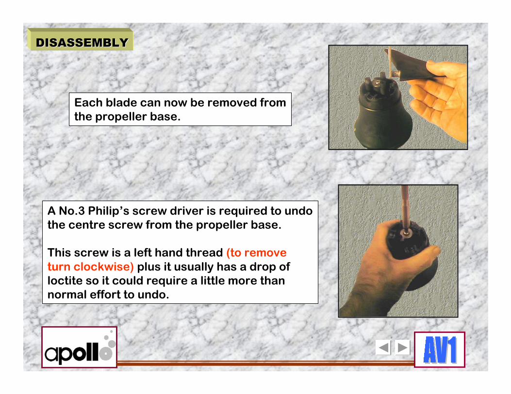
Each blade can now be removed fromthe propeller base.
A No.3 Philip’s screw driver is required to undothe centre screw from the propeller base.
This screw is a left hand thread (to removeturn clockwise) plus it usually has a drop ofloctite so it could require a little more thannormal effort to undo.
DISASSEMBLYDISASSEMBLY

The drive pin must be removed from thepropeller shaft next. This, at times, canbe bent and may require straighteningbefore removal. Align the pin with theslots in the casing before removal.
DISASSEMBLYDISASSEMBLY
Lift the propeller base from the shaft.
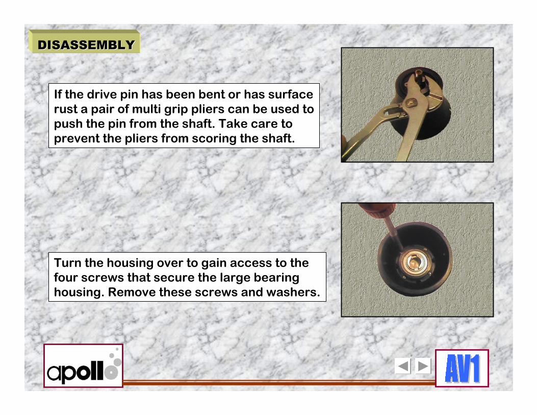
If the drive pin has been bent or has surfacerust a pair of multi grip pliers can be used topush the pin from the shaft. Take care toprevent the pliers from scoring the shaft.
Turn the housing over to gain access to thefour screws that secure the large bearinghousing. Remove these screws and washers.
DISASSEMBLYDISASSEMBLY
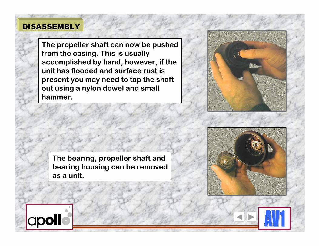
The propeller shaft can now be pushedfrom the casing. This is usuallyaccomplished by hand, however, if theunit has flooded and surface rust is present you may need to tap the shaftout using a nylon dowel and smallhammer.
The bearing, propeller shaft andbearing housing can be removedas a unit.
DISASSEMBLYDISASSEMBLY

DISASSEMBLYDISASSEMBLY
After removing the large ‘C’ ring from thepropeller shaft support the bearing by theinner race in a suitable vice, using a nylonrod and small hammer,gently tap the shaftthrough the bearing.
The bearing housing is separatedfrom the bearing by hand.

Position the case with the seal side up andremove the four countersunk screwssecuring the FA seal retainer, removethe retainer.
Use an o ring pick, taking care not toscore the sealing surface, remove theseal retainer o ring from around the outeredge of the seal. Discard this o ring it isto be replaced after each removal.
DISASSEMBLYDISASSEMBLY

Using a screw driver or suitableprobe prise up the FA seal, remove and discard.
DISASSEMBLYDISASSEMBLY

Turn the propeller casing over to gainaccess to the small bearing retainer.Remove the four screws securing theretainer.
DISASSEMBLYDISASSEMBLY
Lift out the bearing retainer.

Place the casing on a solid surface(wide diameter down) and gentlypush or tap out the bearing.
The dismantling of the propeller casingand its components is now complete.
DISASSEMBLYDISASSEMBLY

INSPECTIONINSPECTION
PLASTIC COMPONENTSPLASTIC COMPONENTS
All non metal parts are to be cleaned in warmwater and detergent using a brush to removeany built up grease or stains.
Dry with a lint free cloth or blow dry with clean air.
After cleaning check the o ring sealing surfacesfor scoring or gouge marks.
SEALSSEALS
The FA seal P/No. 3993600000 together withseal o ring P/No.3993000022 are to be replaced after each disassembly.

INSPECTIONINSPECTION
PROPELLER SHAFTPROPELLER SHAFT
A critical sealing area to be checked using a magnifyingglass is the sealing area for the FA seal.
Although the seal is rubber after prolonged use it canwear a groove in the metal shaft.
Any sign of pitting or grooving requires the shaft to bereplaced.
Check both ends of the shaft for burrs, these canprevent assembly later. Any burrs can be carefullyremoved using a small warding file.

INSPECTIONINSPECTION
RETAINERS, SCREWS, WASHERS etc.RETAINERS, SCREWS, WASHERS etc.
Stainless steel parts, seal retainers together withscrews and washers can become contaminated withsurface rust.
Most surface rust can be removed by polishing with afine grade of ‘Scotch Brite’ (nylon scourer) afterpolishing all metal parts should be acid bathed,rinsed, dried and then examined for any surfacepitting from corrosion.
If pitting is evident the faulty parts must be replaced.

INSPECTIONINSPECTION
BEARINGS BEARINGS
The large bearing (P/No.399 02 00 003) andthe small bearing (P/No.399 02 00 002) mustbe inspected prior to refitting.
Any sign of surface rust is an indication thatcorrosion could be present on the internalballs and races.
The bearings are sealed and pre-lubricated so the bearings must not be immersed in any solvent cleaning baths, this will wash out thelubricant and there is no way to repack thebearings.
Any signs of corrosion, stiffness or rough rotation and the bearings must be replaced.

INSPECTIONINSPECTION
PROPELLER BLADESPROPELLER BLADES
Blades can become bent at the support armsif the scooter has suffered an entanglement.Check carefully to prevent installing a bent blade.
CLUTCH PLATESCLUTCH PLATES
Wear to the clutch plates can also result fromentanglements. To check for wear or damagethe plates must be removed, the wear markswill appear on the top and bottom plates onthe side that faces the balls. Any sign of agroove between the outer holes worn by theballs will require the plate/s to be replaced.

ASSEMBLYASSEMBLY
Prior to assembly ensure allparts havebeen cleaned and inspected forflaws.
To commence the assembly place the smallbearing into the casing. The bearing can bepressed into the casing by hand.The bearing is symmetrical so either sidecan face up.

ASSEMBLYASSEMBLY
The bearing retainer is now fitted,the round edged side should faceupwards.
Secure the retainer using four shortshank round head No.1 Philip’s screws.
CAUTION : Many of the screws fittedduring assembly will be secured intoplastic threads, care must be taken not to over tighten and strip threadstherefore requiring expensive partsto be replaced.

ASSEMBLYASSEMBLY
Fit the ‘C’ ring to the propeller shaft,then install the shaft through thesmall bearing. Press the shaft homeby hand, if the shaft cannot be installedby hand check for burrs on the shaft.
The large bearing is now pressedby hand into the bearing housing.

ASSEMBLYASSEMBLY
The bearing is set flush into the housing.
The large bearing and housing are nowfitted to the shaft. The housing flangeside (wide diameter) facing down.

ASSEMBLYASSEMBLY
The bearing and housing arepressed home by hand.
Secure the bearing housing into thecasing, use four long shank roundhead No.1 Philip’s screws with foursmall flat washers.
The propeller shaft and bearing should nowbe secure. Test for smooth rotation byspinning the shaft, if using old bearingscheck carefully for any binding.

ASSEMBLYASSEMBLY
NOTE : There are two types of knifeedge seal used on the AV1, the FAseal fitted on the propeller shaft hasa small spring around the knife edgeplus has a metal housing. The motor shaft seal is all rubber.Ensure the correct seal is used.
Lubricate the FA seal with silicone grease.Smear the lubrication on the opposite sideto the spring, this will ensure the knife edgehas lubrication after being installed.

ASSEMBLYASSEMBLY
Press the seal gently around theedges until it is flush in the casing.
The seal is installed with theflat face down.

ASSEMBLYASSEMBLY
A new bearing o ring is lightly lubricatedwith silicone grease and installed in thegroove around the outer edge of the bearing.
Ensure the o ring is in position,fit the bearing retainer. The countersunk holes in theretainer face up.

Secure the retainer using fourPhilip’s head counter sunk screws.
Line up the drive pin holes in the shaftwith the slots in the casing and installthe drive pin. Ensure the pin is centred.
ASSEMBLYASSEMBLY

ASSEMBLYASSEMBLY
The propeller base can now be fitted. The drive pin must be located in themoulded slot of the base, shown in the picture, or there will be no drive.
The clutch screw assembly is now fitted.The star washer sits on the boss first,next the spring cup washer, the inneredge should sit on the star washer and the outer edge is curved up.

ASSEMBLYASSEMBLY
A drop of ‘Loctite 243’ is used on the thread of the screw. ( No. 3 Philip’shead )
The flat washer is fitted to thescrew and the screw installed.
ASSEMBLYASSEMBLY
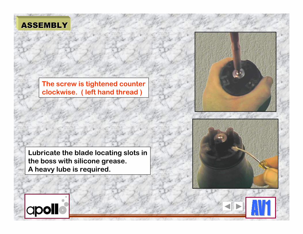
The screw is tightened counterclockwise. ( left hand thread )
Lubricate the blade locating slots inthe boss with silicone grease.A heavy lube is required.

ASSEMBLYASSEMBLY
Install the propeller retainer taking careto align the blade arms through the slotsin the retainer.
Install each blade as shown. The exposedpart of each blade shaft (where they locatein the boss) are now lubricated with siliconegrease.

ASSEMBLYASSEMBLY
Position the three blade arms centre(straight up) the pitch knob is now carefully lowered over the arms.
Three No.2 Philip’s head screws withstar washers are fitted and carefullytightened. ( into plastic threads )

ASSEMBLYASSEMBLY
The pitch knob return spring, countersunkwasher and counter sunk screw are nowinstalled. Lubricate the spring with siliconegrease prior to installation.
Ensure the pitch numbers (1, 2, 3)on the adjusting knob are alignedwith the numbers on the propellerretainer. If the blade arms are facing straightup pitch setting 2 must be aligned.

ASSEMBLYASSEMBLY
Final checks can now be carried out.Ensure the blades spin freely.Check the operation of the pitch settingknob.
Using a No.3 Philip’s screw drivertighten the pitch knob retaining screw.