proper nmea 2000 installation ibex 2012 session 813 ibex full nmea installation.pdf · proper nmea...
TRANSCRIPT
Proper NMEA 2000 Installation IBEX 2012 Session 813
Part I Physical Installation
Dave Morschhauser, Mystic Valley Communications Pete Braffitt, Gemeco

Overview
• What is NMEA 2000? • What are its physical characteristics and
limits? • What makes a good NMEA 2000 network? • What makes a good NMEA 2000 network
fail?

NMEA 2000
• Marine specific network for navigation, control, and monitoring
• CAN based, similar to J1939 • Uses industrial quality cabling originally
developed for DeviceNET • Certified products, based on standard
certification tool

NMEA 2000 Certification
• First certification program applicable to recreational marine electronic products
• Over 400 products certified to date • Purpose: ensure products communicate
cooperatively (plug and play) • Based on common certification tool • Cabling components are also approved

NMEA 2000

Typical Tee
Drop Connection to device (FEMALE)- Accepts drop cable.
MALE Backbone
Connection
FEMALE Backbone
Connection

NMEA 2000
• Single backbone cable snakes throughout the vessel
• No active network infrastructure to fail • Standardized message structure and format
– both generic and system specific messages • Links vessel systems together
– engines, navigation, power distribution, water & waste, etc.

NMEA 2000 = Vessel Database

What can you do with NMEA 2000?

Physical Construction
• Building Blocks • Characteristics • Power Availability • Other considerations
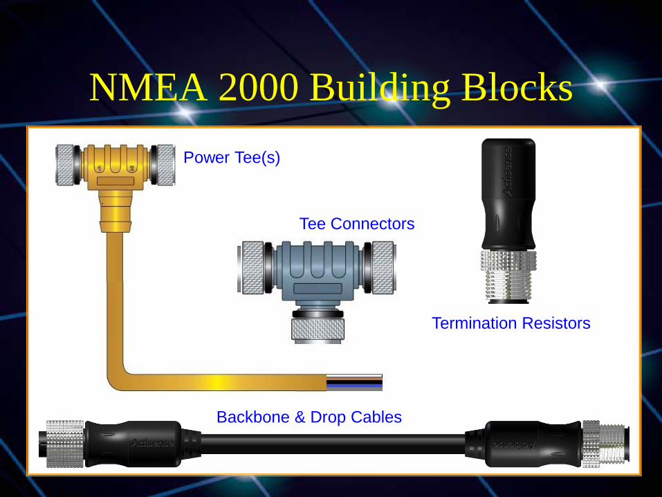
NMEA 2000 Building Blocks Power Tee(s)
Tee Connectors
Termination Resistors
Backbone & Drop Cables
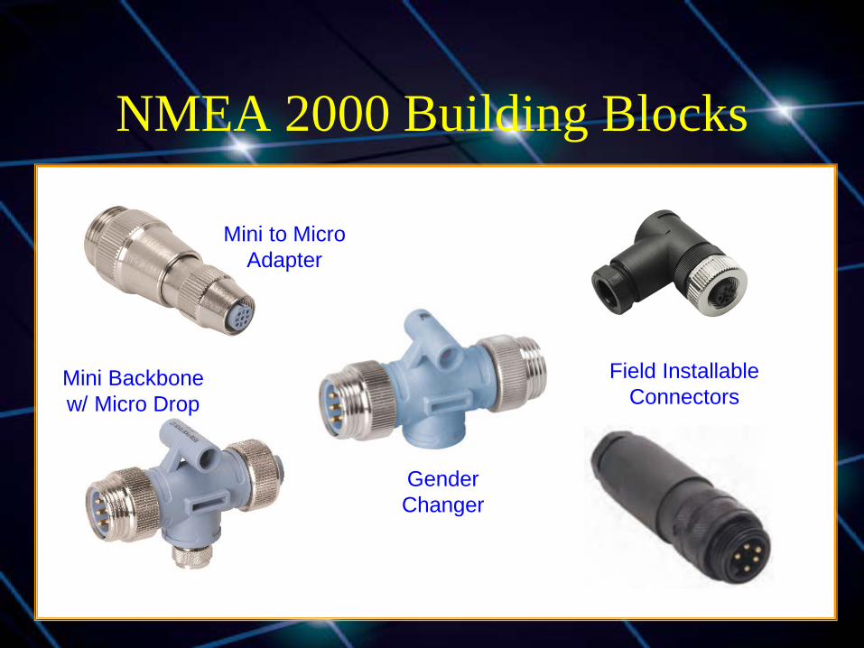
NMEA 2000 Building Blocks
Mini to Micro Adapter
Mini Backbone w/ Micro Drop
Gender Changer
Field Installable Connectors
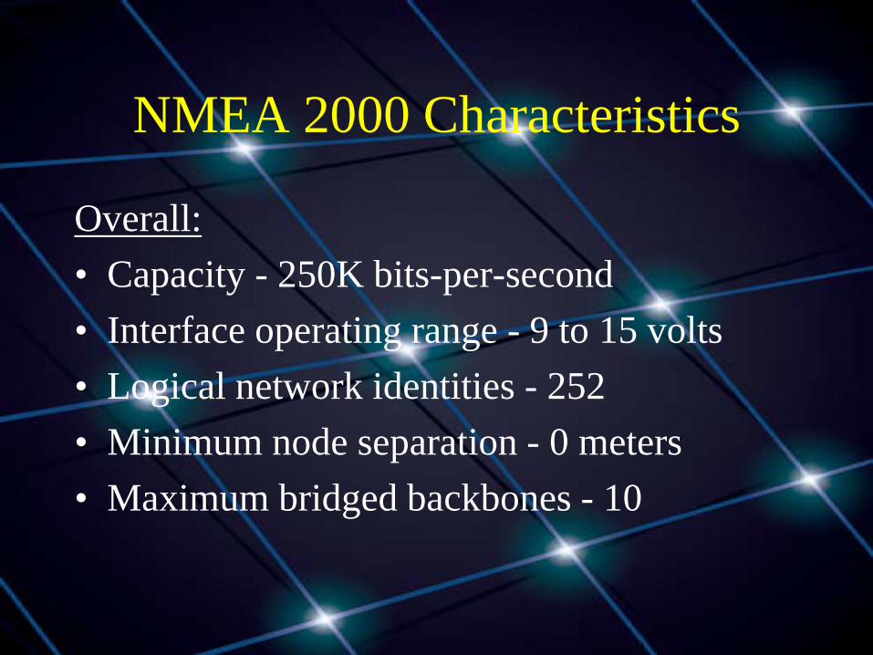
NMEA 2000 Characteristics
Overall: • Capacity - 250K bits-per-second • Interface operating range - 9 to 15 volts • Logical network identities - 252 • Minimum node separation - 0 meters • Maximum bridged backbones - 10

NMEA 2000 Characteristics
Each backbone: • Length - 200 meters
– 100 meters when using light cable • Connected products - 50 • Drop cable
– 6 meters per drop – 78 meters total of all drops
• Power - limited by cable size and the number of power insertion points
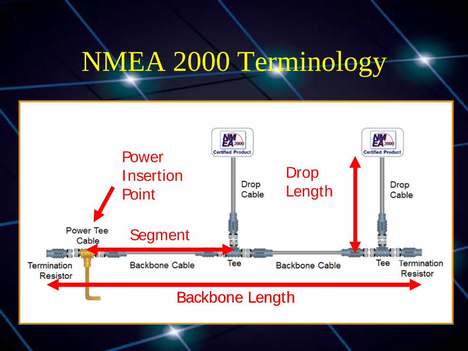
NMEA 2000 Terminology
Backbone Length
Drop Length
Power Insertion Point
Backbone Length
Segment
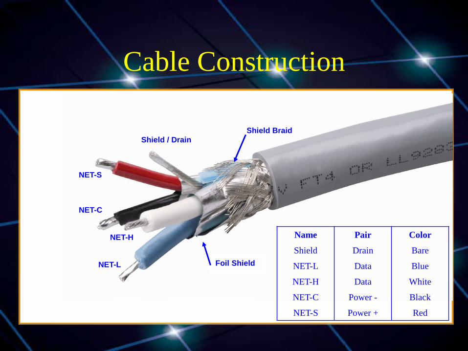
Cable Construction
Shield / Drain
NET-S
NET-C
NET-H
NET-L
Name Pair Color
Shield Drain Bare
NET-L Data Blue
NET-H Data White
NET-C Power - Black
NET-S Power + Red
Shield Braid
Foil Shield
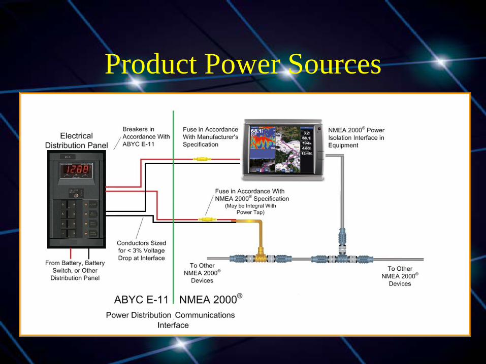
Product Power Sources
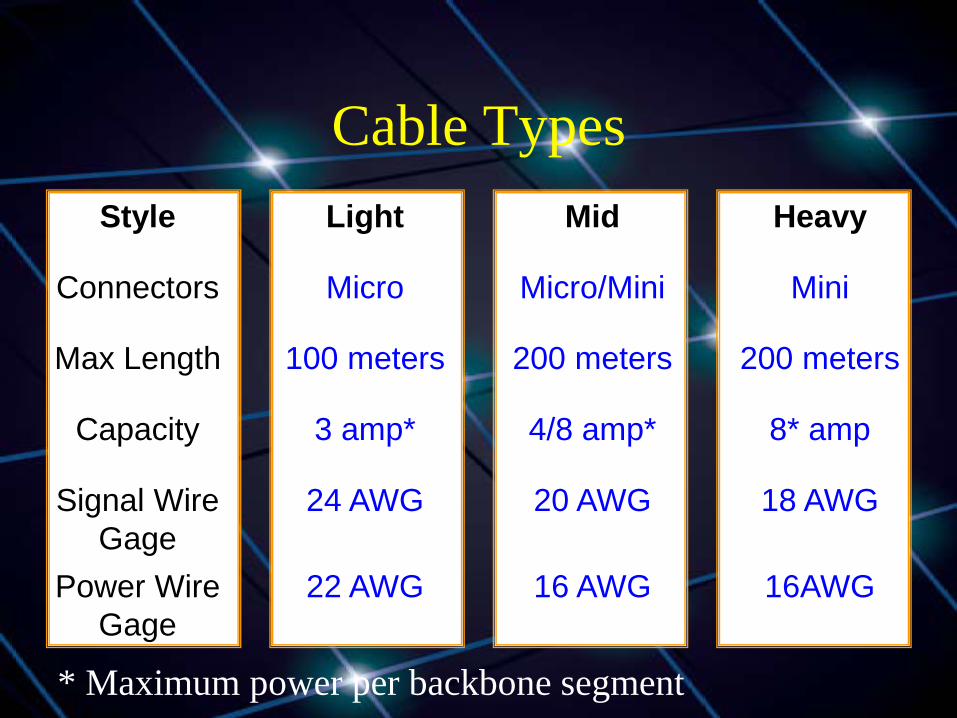
Cable Types Style Light Mid Heavy
Connectors Micro Micro/Mini Mini
Max Length 100 meters 200 meters 200 meters
Capacity 3 amp* 4/8 amp* 8* amp
Signal Wire Gage
24 AWG 20 AWG 18 AWG
Power Wire Gage
22 AWG 16 AWG 16AWG
* Maximum power per backbone segment

NMEA 2000 Backbone
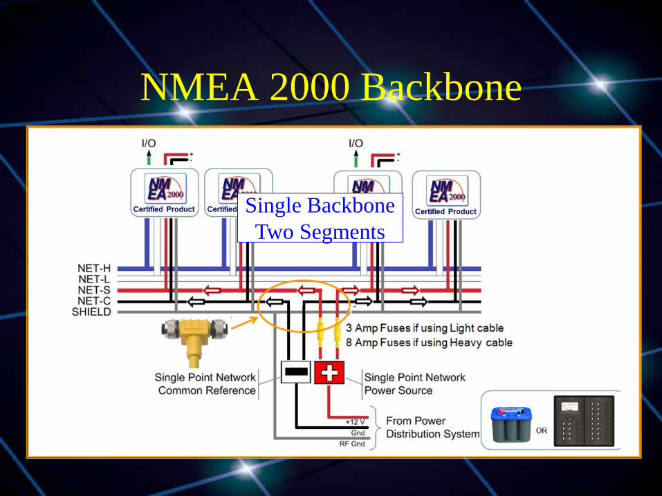
NMEA 2000 Backbone
Single Backbone Two Segments

Power Sources
• Battery (nominally 12.0 VDC) – Allowed voltage drop = 1.5 VDC
• Typical power supply (13.8 VDC) – Allowed voltage drop = 3.0 VDC
• Maximum power supply (15 VDC) – Maximum allowed voltage drop = 5.0 VDC
Other Considerations
• Products may be added to or removed from the backbone while operational
• No daisy-chaining ensures backbone remains intact when removing equipment
• Two terminators required, one at each end of the backbone

Making the Right Selections
Network Design Drivers
• Network power distribution – Segment voltage drop limit – Add power insertions points as needed
• Network topology – Keep it pure
Network Voltage Drop
• Straightforward application of Ohm’s Law
where E = voltage drop I = circuit current R = wire resistance
E = I x R
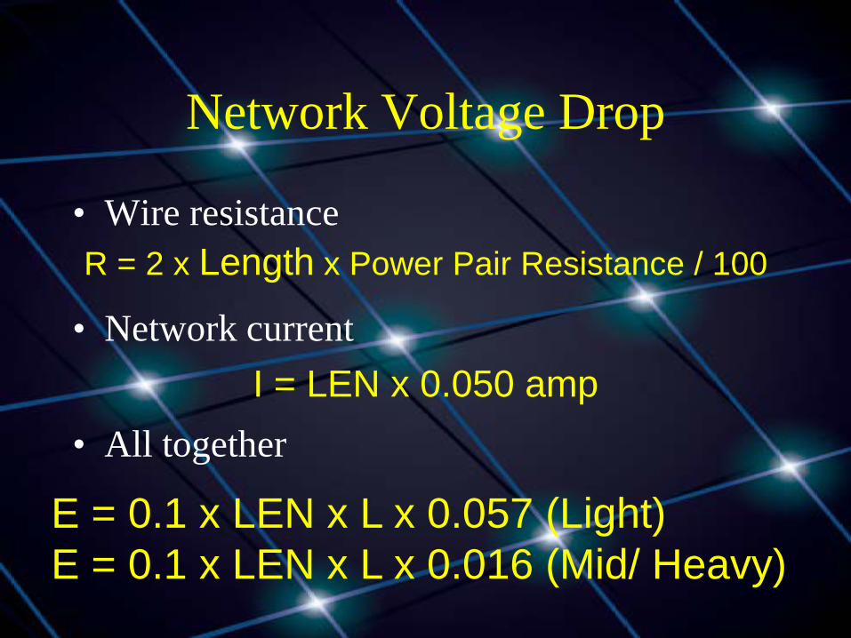
Network Voltage Drop
• Wire resistance
• Network current
• All together
R = 2 x Length x Power Pair Resistance / 100
I = LEN x 0.050 amp
E = 0.1 x LEN x L x 0.057 (Light) E = 0.1 x LEN x L x 0.016 (Mid/ Heavy)

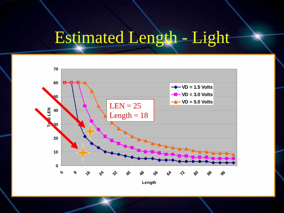
Estimated Length - Light
0
10
20
30
40
50
60
70
0 8 16 24 32 40 48 56 64 72 80 88 96
Length
Tota
l LEN
VD = 1.5 VoltsVD = 3.0 VoltsVD = 5.0 Volts
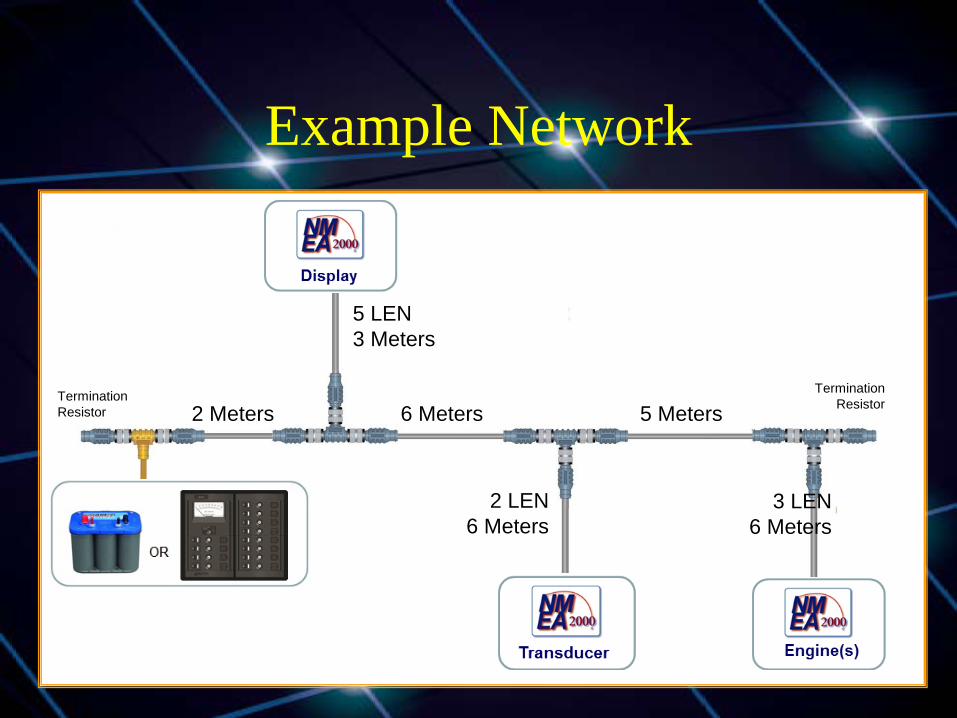
Example Network
2 Meters 5 Meters 6 Meters
3 LEN 6 Meters
2 LEN 6 Meters
5 LEN 3 Meters
Termination Resistor
Termination Resistor
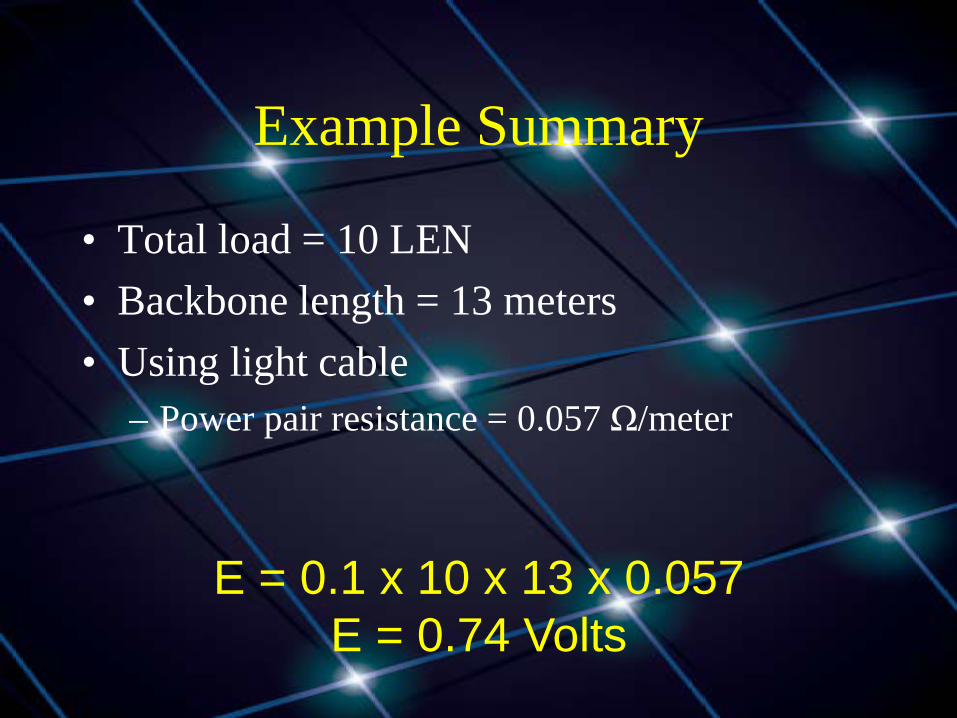
Example Summary
• Total load = 10 LEN • Backbone length = 13 meters • Using light cable
– Power pair resistance = 0.057 Ω/meter
E = 0.1 x 10 x 13 x 0.057 E = 0.74 Volts
Estimated Length - Light
0
10
20
30
40
50
60
70
0 8 16 24 32 40 48 56 64 72 80 88 96
Length
Tota
l LEN
VD = 1.5 VoltsVD = 3.0 VoltsVD = 5.0 VoltsLEN = 25
Length = 18
Network Layout
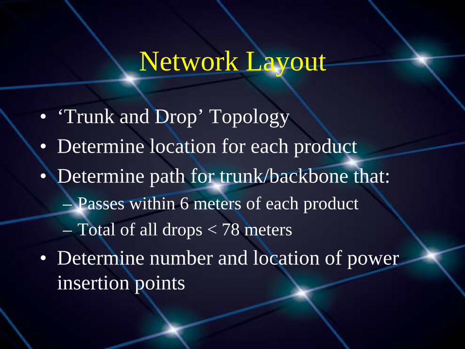
• ‘Trunk and Drop’ Topology • Determine location for each product • Determine path for trunk/backbone that:
– Passes within 6 meters of each product – Total of all drops < 78 meters
• Determine number and location of power insertion points
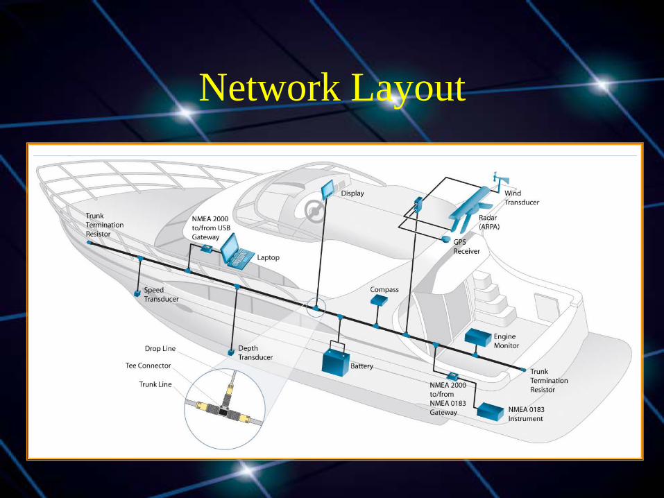
Network Layout

Layout Issues
• Multiple connections in confined spaces • Sailboat masts & powerboat towers • Gateways to other protocols • Multiple backbone configurations
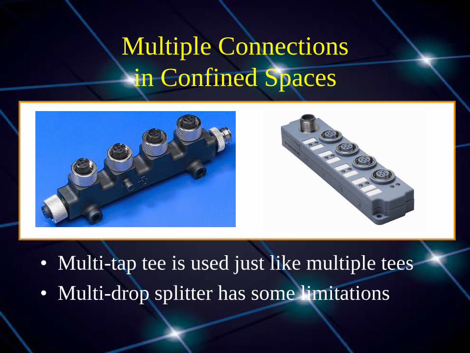
Multiple Connections in Confined Spaces
• Multi-tap tee is used just like multiple tees • Multi-drop splitter has some limitations
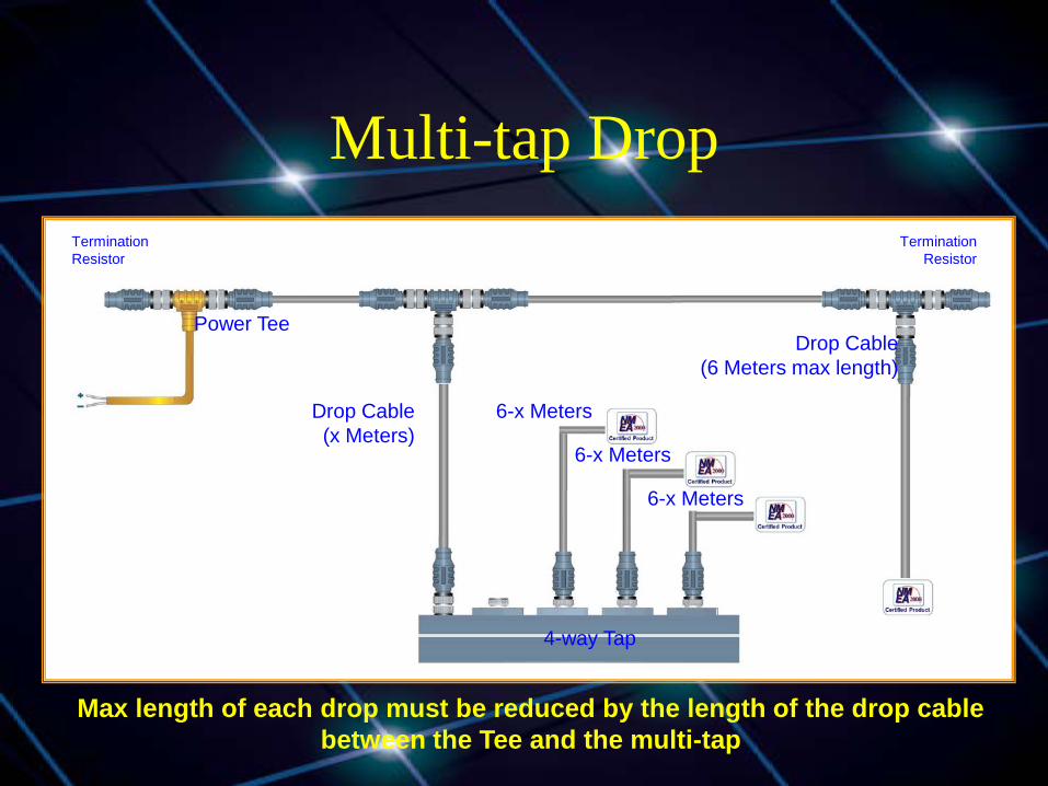
Multi-tap Drop
Power Tee
4-way Tap
Drop Cable (6 Meters max length)
Drop Cable (x Meters)
6-x Meters
6-x Meters
6-x Meters
Termination Resistor
Termination Resistor
Max length of each drop must be reduced by the length of the drop cable between the Tee and the multi-tap
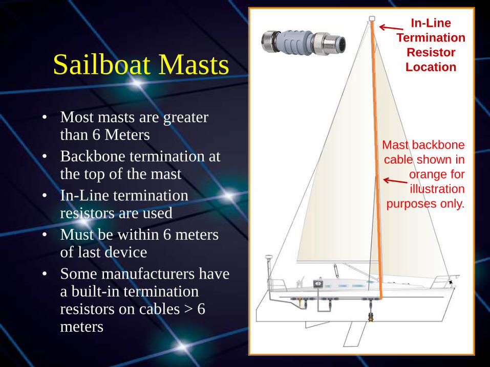
Sailboat Masts • Most masts are greater
than 6 Meters • Backbone termination at
the top of the mast • In-Line termination
resistors are used • Must be within 6 meters
of last device • Some manufacturers have
a built-in termination resistors on cables > 6 meters
In-Line Termination
Resistor Location
Mast backbone cable shown in
orange for illustration
purposes only.
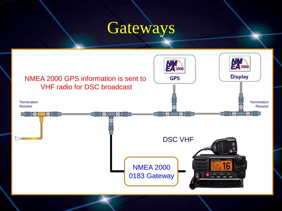
Gateways
NMEA 2000 0183 Gateway
DSC VHF
NMEA 2000 GPS information is sent to VHF radio for DSC broadcast
Termination Resistor
Termination Resistor
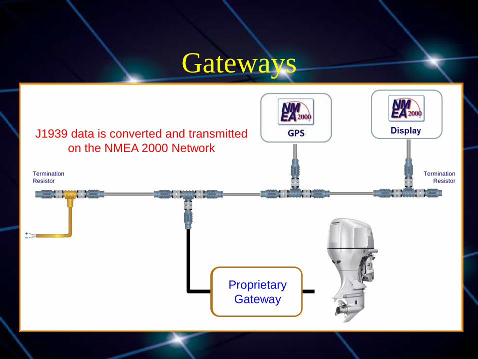
Gateways
NMEA 2000 J1939 Gateway
J1939 data is converted and transmitted on the NMEA 2000 Network
Termination Resistor
Termination Resistor
Proprietary Gateway
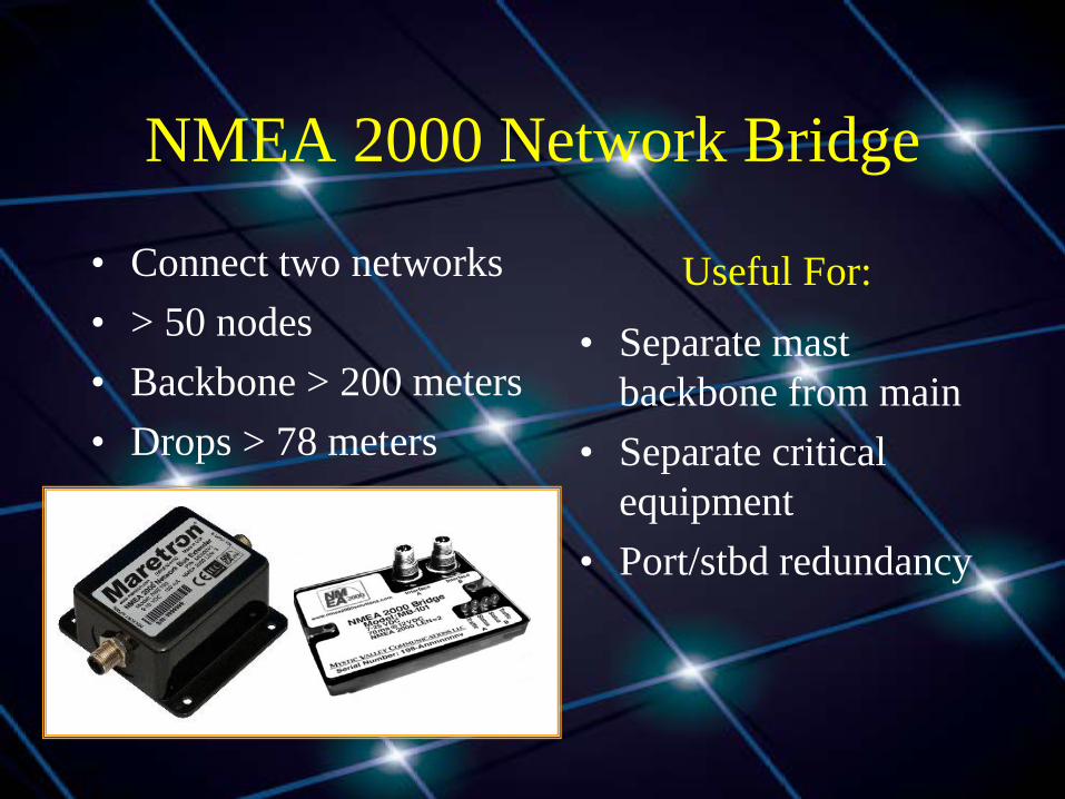
NMEA 2000 Network Bridge
• Connect two networks • > 50 nodes • Backbone > 200 meters • Drops > 78 meters
• Separate mast backbone from main
• Separate critical equipment
• Port/stbd redundancy
Useful For:
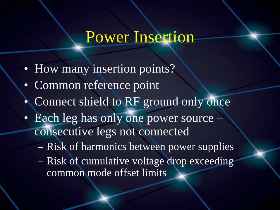
Power Insertion
• How many insertion points? • Common reference point • Connect shield to RF ground only once • Each leg has only one power source –
consecutive legs not connected – Risk of harmonics between power supplies – Risk of cumulative voltage drop exceeding
common mode offset limits

Power Insertion
Shield/Drain left unconnected at all
other insertion points
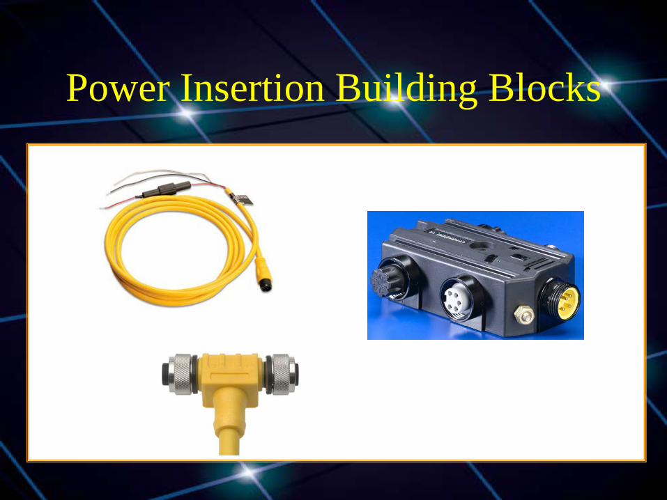
Power Insertion Building Blocks
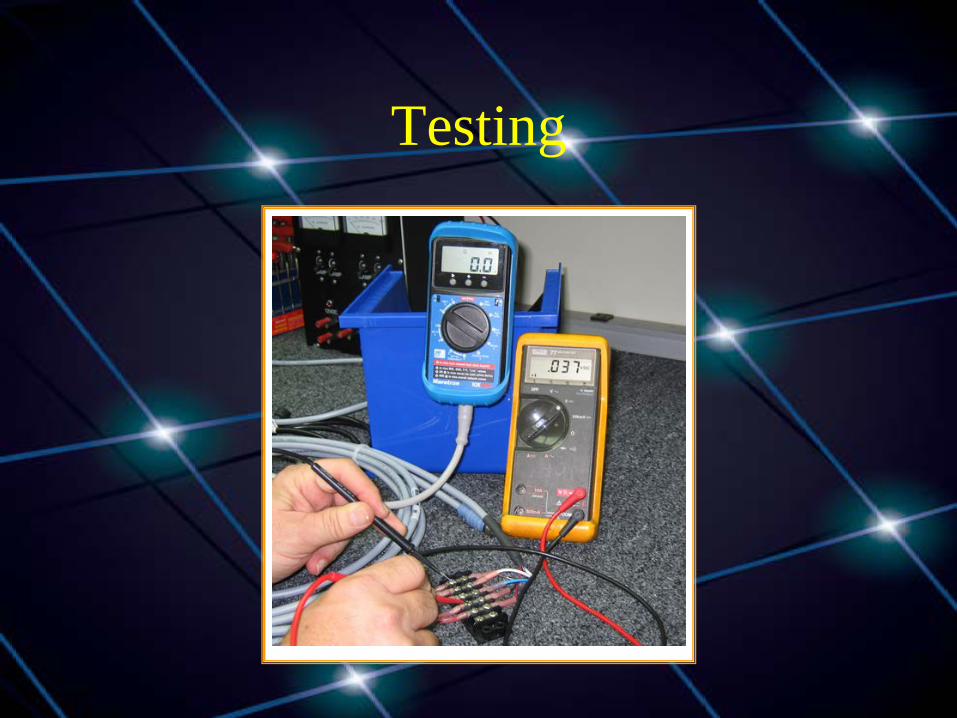
Testing
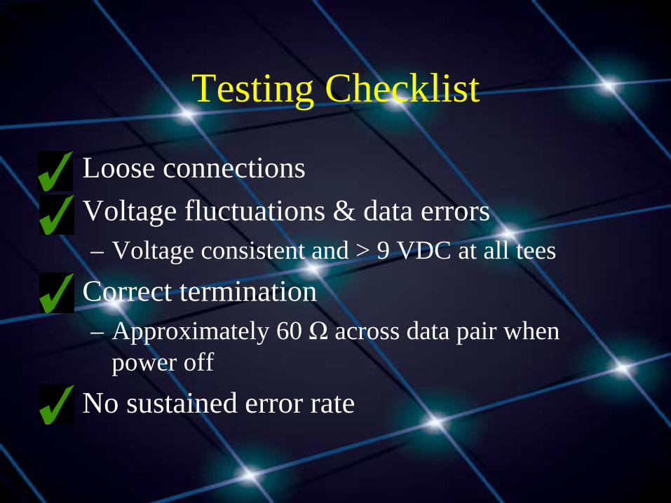
Testing Checklist
• Loose connections • Voltage fluctuations & data errors
– Voltage consistent and > 9 VDC at all tees • Correct termination
– Approximately 60 Ω across data pair when power off
• No sustained error rate
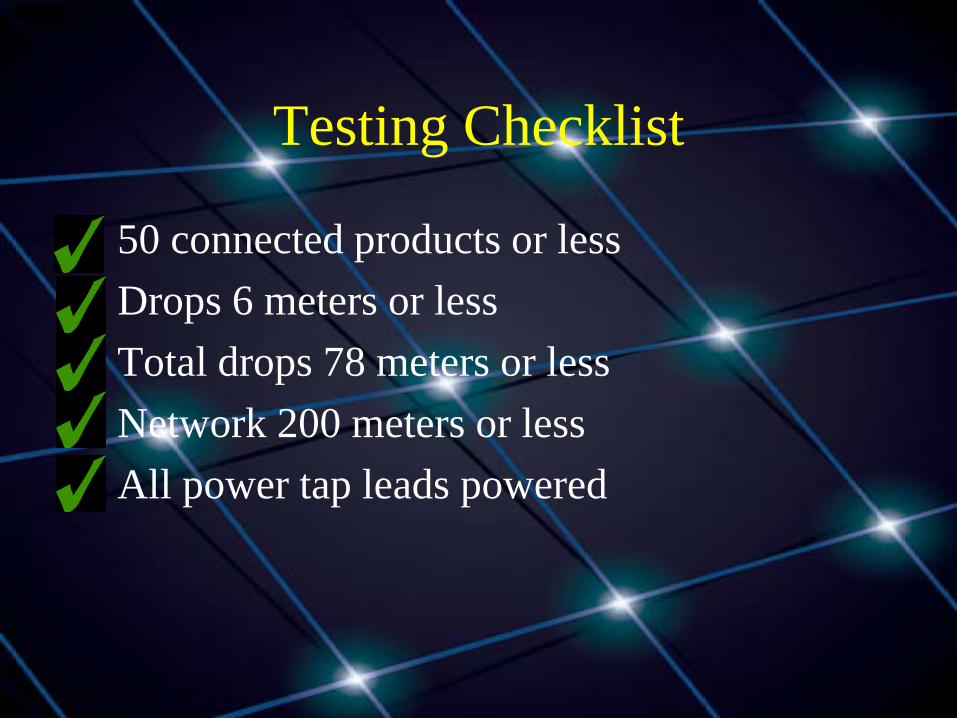
Testing Checklist
• 50 connected products or less • Drops 6 meters or less • Total drops 78 meters or less • Network 200 meters or less • All power tap leads powered
Plug and Play Limitation
• Layout and power planning rules result in products communicating non-destructively
• Product configuration ensures data displayed is data intended
• Manufacturer configurability may vary • New Label and Configuration messages will
unify methods in use

Acknowledgements and Contact Information
Photos courtesy of Airmar, Actisense, Garmin, LTW, Maretron, Molex, Turck Diagrams courtesy NMEA
Contact Information: David Morschhauser [email protected]
http://www.nmea2000solutions.com
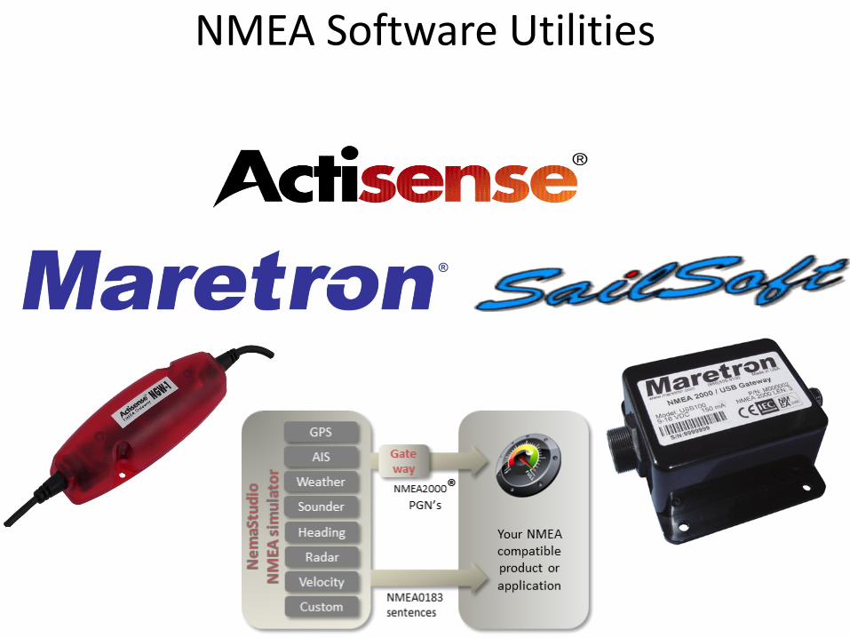
NMEA Software Utilities

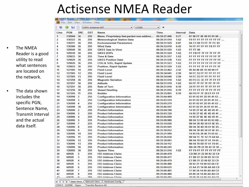
Actisense NMEA Reader
• The Actisense NMEA Reader is a great utility for testing and evaluating a NMEA 0183 or NMEA 2000™ system.
• The program is free to download from the Actisense web site and will work great with a compatible serial or USB adapter.
• This software will allow the user to view real time data flow and buffer rates.
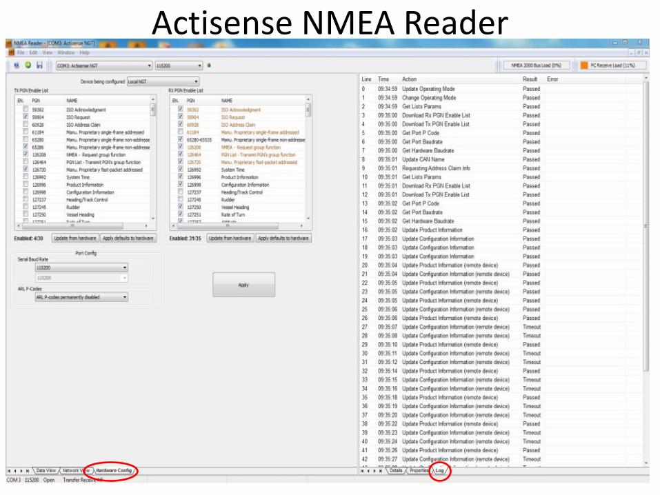
• Certain Actisense gateways can be programmed by this software such as the NGW-1 and NGT-1.
• Manufacturer and LEN numbers can be obtained from this software for certain NMEA 2000™ devices.

• The Actisense NGT-1-USB is a great product to deliver NMEA 2000™ data directly into the PC for use with the NMEA Reader Software.
Actisense NMEA Reader
Actisense NGT-1-USB
Actisense NMEA Reader
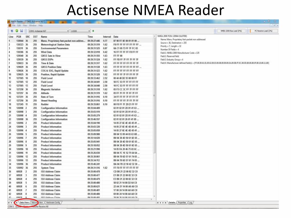
• The NMEA Reader is a good utility to read what sentences are located on the network.
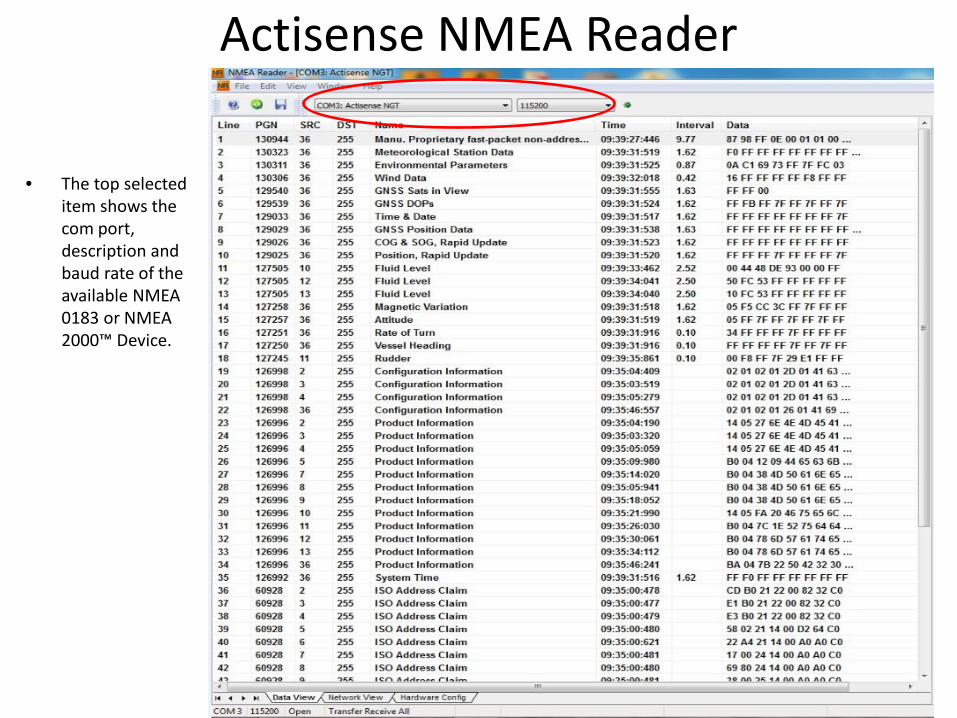
• The data shown includes the specific PGN, Sentence Name, Transmit Interval and the actual data itself.
Actisense NMEA Reader
• The top selected item shows the com port, description and baud rate of the available NMEA 0183 or NMEA 2000™ Device.
Actisense NMEA Reader
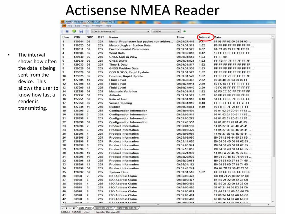
• The interval shows how often the data is being sent from the device. This allows the user to know how fast a sender is transmitting.
Actisense NMEA Reader
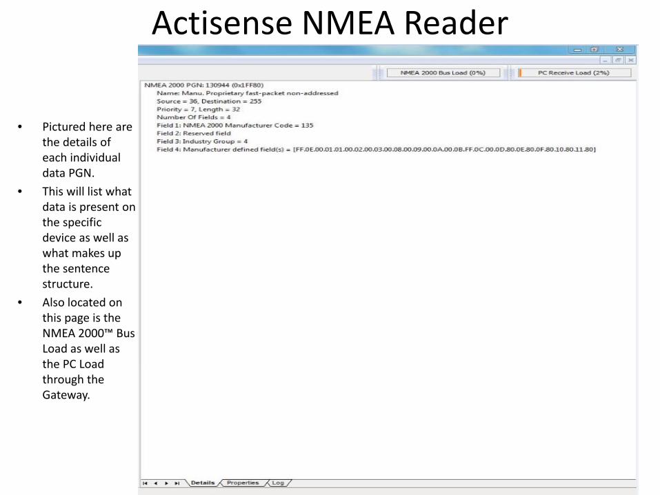
• Pictured here are the details of each individual data PGN.
• This will list what data is present on the specific device as well as what makes up the sentence structure.
• Also located on this page is the NMEA 2000™ Bus Load as well as the PC Load through the Gateway.
Actisense NMEA Reader
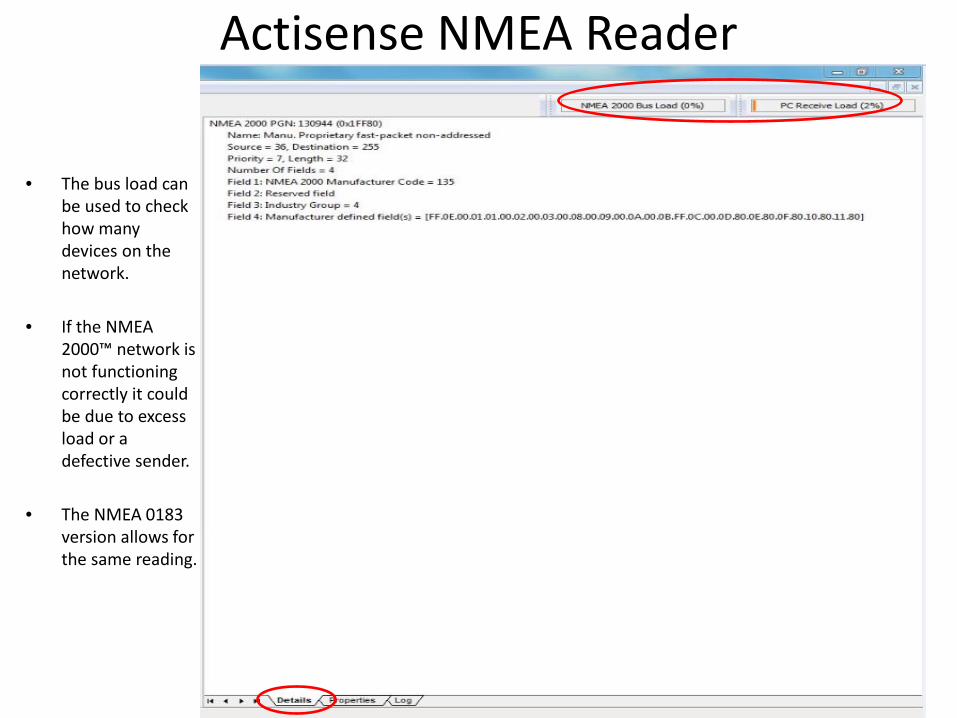
• The bus load can be used to check how many devices on the network.
• If the NMEA 2000™ network is not functioning correctly it could be due to excess load or a defective sender.
• The NMEA 0183 version allows for the same reading.
Actisense NMEA Reader
Actisense NMEA Reader
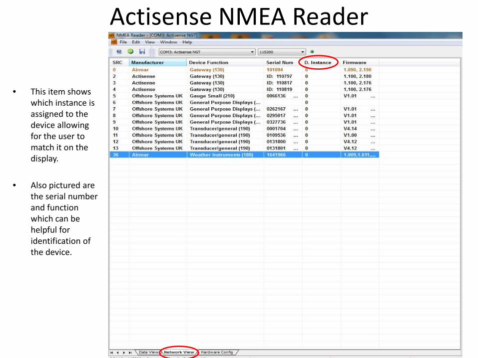
• This item shows which instance is assigned to the device allowing for the user to match it on the display.
• Also pictured are the serial number and function which can be helpful for identification of the device.
Actisense NMEA Reader
Sail Soft NEMA Studio
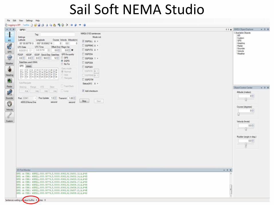
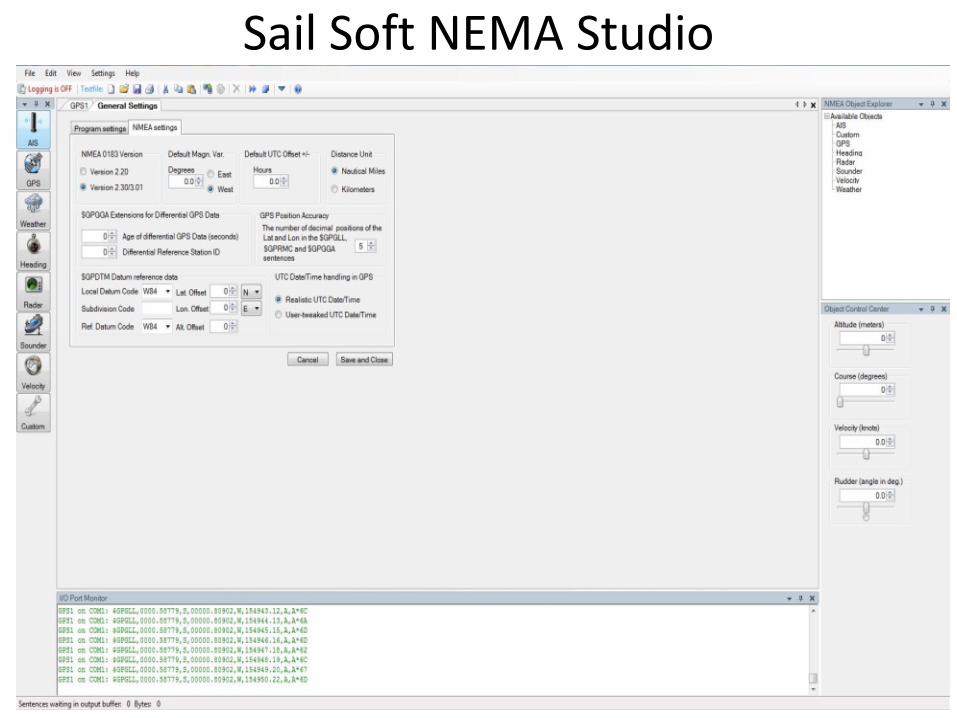
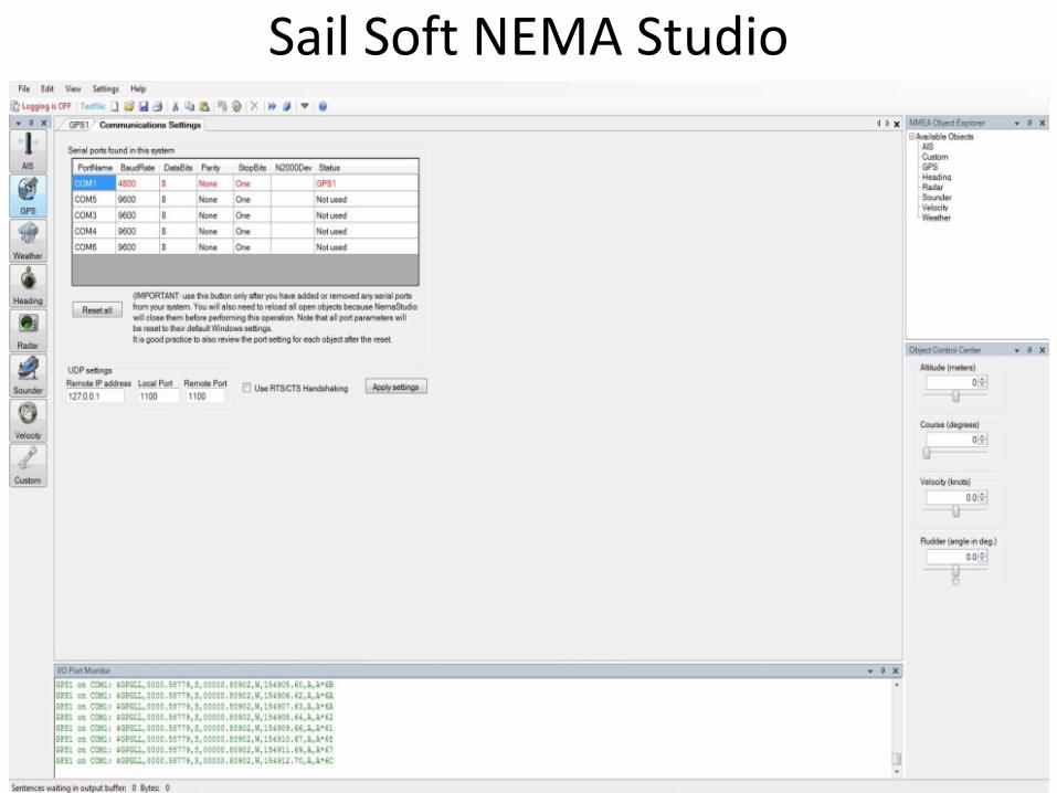
• The Sail Soft program will allow data to be sent from a PC via NMEA 0183 on a user selected Com Port.
• This will allow for testing of displays or networks by sending out select amounts of data which is controlled through the software.
• The data that is being transmitted via NMEA 0183 can then be converted to NMEA 2000™ using either an NGW-1, AT-10 or any other NMEA approved device.
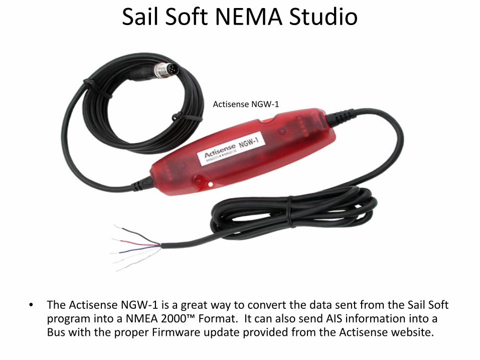
• The Actisense NGW-1 is a great way to convert the data sent from the Sail Soft program into a NMEA 2000™ Format. It can also send AIS information into a Bus with the proper Firmware update provided from the Actisense website.
Sail Soft NEMA Studio
Actisense NGW-1
Sail Soft NEMA Studio
Sail Soft NEMA Studio
Sail Soft NEMA Studio
• The Maretron N2KAnalyzer Software is free to download from the Maretron Web site and offers many valuable options for network evaluation and testing.
• The N2KAnalyzer requires the use of a Maretron USB100 Gateway to properly connect to a NMEA 2000™ system.
• Maretron’s software will allow a user to assign device instances to components directly.
• The software also shows software version, manufacturer, serial numbers and much more data specific to a sensor.
Maretron N2KAnalyzer

Maretron N2KAnalyzer
• The Maretron USB100 Gateway will allow the NMEA 2000™ network to be accessed by the N2KAnalyzer to show what devices are attached. The Gateway will also allow devices to be programmed for instances and queried for transmitted and received PGN’s.
USB100 Gateway

• The Main Device page will show what devices are connected to the Network and the specific information of that device.
Maretron N2KAnalyzer N2KAnalyzer Software Device Page
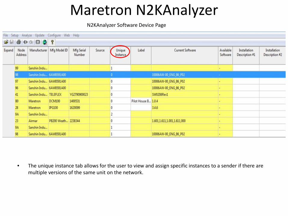
• The unique instance tab allows for the user to view and assign specific instances to a sender if there are multiple versions of the same unit on the network.
Maretron N2KAnalyzer N2KAnalyzer Software Device Page
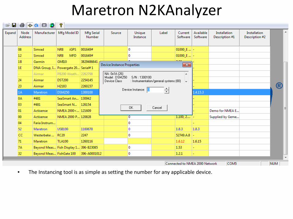
• The Instancing tool is as simple as setting the number for any applicable device.
Maretron N2KAnalyzer N2K Analyzer Software Device Page

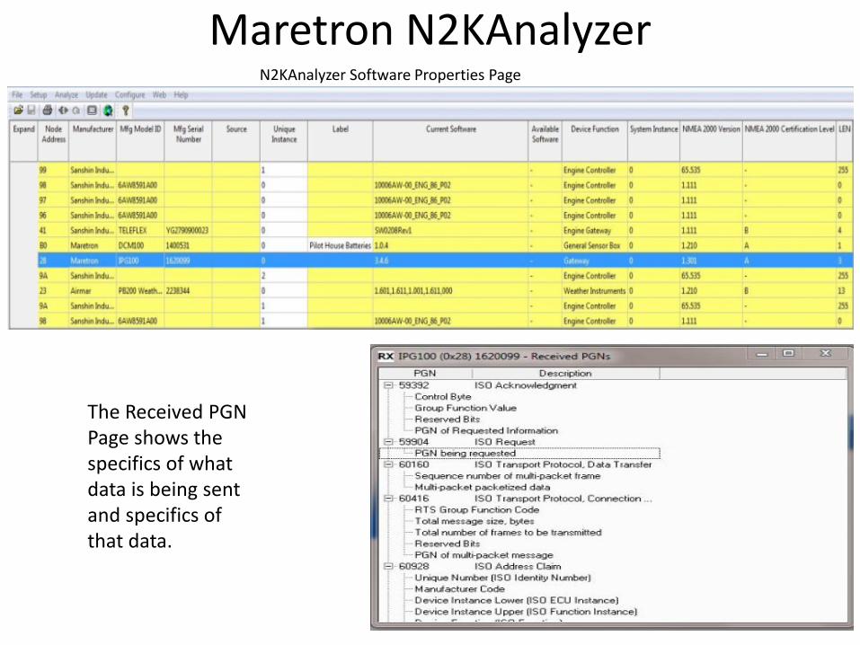
Maretron N2KAnalyzer N2KAnalyzer Software Properties Page
The PGN Page shows all transmitted and received sentences to ensure proper operation.
Maretron N2KAnalyzer N2KAnalyzer Software Properties Page
The Received PGN Page shows the specifics of what data is being sent and specifics of that data.
Maretron N2KAnalyzer N2KAnalyzer Software Properties Page
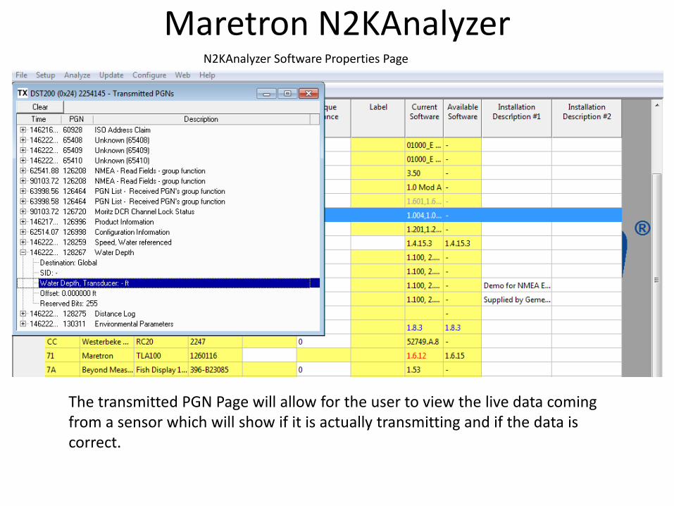
The transmitted PGN Page will allow for the user to view the live data coming from a sensor which will show if it is actually transmitting and if the data is correct.
Maretron N2KAnalyzer N2KAnalyzer Software Properties Page
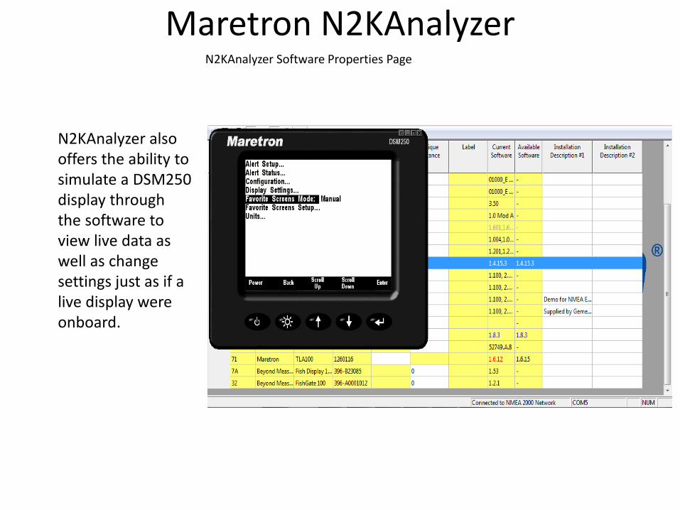
N2KAnalyzer also offers the ability to simulate a DSM250 display through the software to view live data as well as change settings just as if a live display were onboard.
Maretron N2KBuilder
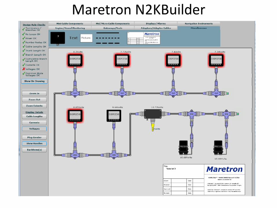
• Maretron’s unique N2KBuilder program allows dealers and installers to design and test networks before any cable is pulled through the vessel.
• The software will calculate voltage drop, connector gender, and cable lengths as well as allow the use of custom parameters to meet most design needs.
• When used properly, a configuration file can be generated to create a bill of material that will include all Maretron parts used in the build that makes ordering parts much more efficient.
N2KBUILDER NMEA 2000™ NETWORK DESIGN SOFTWARE
Maretron N2KBuilder
Maretron N2KBuilder
Maretron N2KBuilder
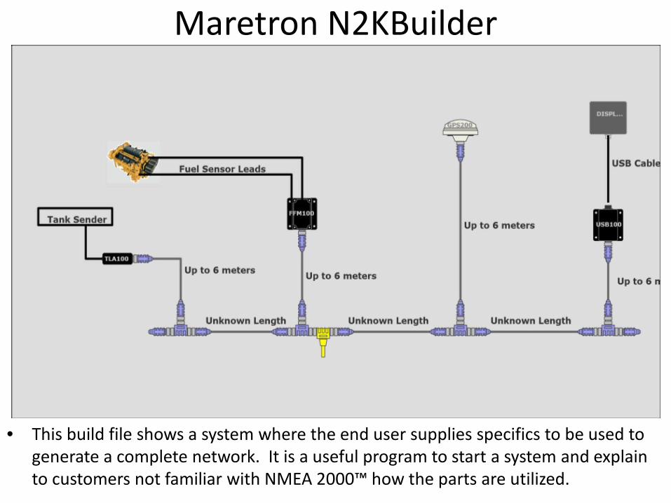
• This build file shows a system where the end user supplies specifics to be used to generate a complete network. It is a useful program to start a system and explain to customers not familiar with NMEA 2000™ how the parts are utilized.
Maretron N2KBuilder
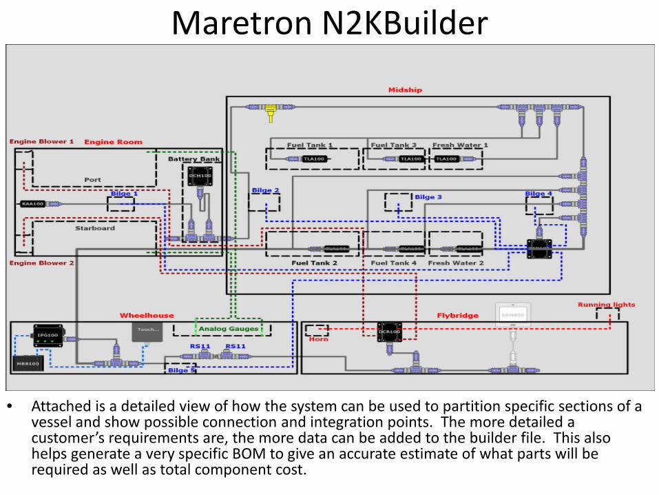
• Attached is a detailed view of how the system can be used to partition specific sections of a vessel and show possible connection and integration points. The more detailed a customer’s requirements are, the more data can be added to the builder file. This also helps generate a very specific BOM to give an accurate estimate of what parts will be required as well as total component cost.
Maretron N2KBuilder
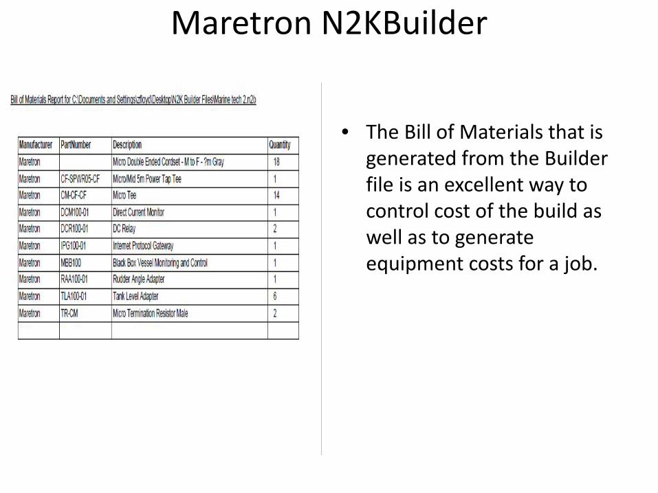
• The Bill of Materials that is generated from the Builder file is an excellent way to control cost of the build as well as to generate equipment costs for a job.
Maretron N2KMeter
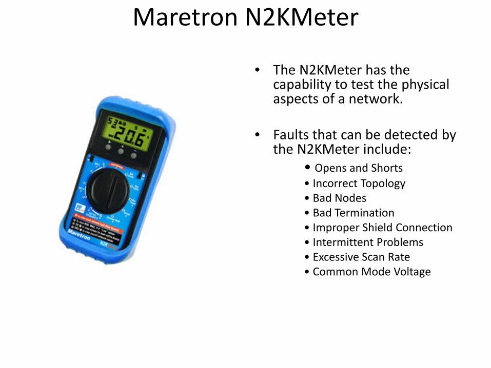
• The N2KMeter has the capability to test the physical aspects of a network.
• Faults that can be detected by the N2KMeter include:
• Opens and Shorts • Incorrect Topology • Bad Nodes • Bad Termination • Improper Shield Connection • Intermittent Problems • Excessive Scan Rate • Common Mode Voltage
Maretron N2KMeter
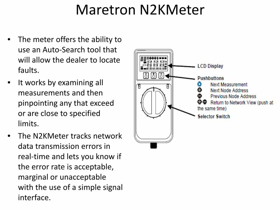
• The meter offers the ability to use an Auto-Search tool that will allow the dealer to locate faults.
• It works by examining all measurements and then pinpointing any that exceed or are close to specified limits.
• The N2KMeter tracks network data transmission errors in real-time and lets you know if the error rate is acceptable, marginal or unacceptable with the use of a simple signal interface.
Maretron N2KMeter
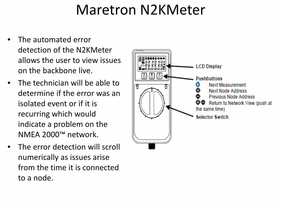
• The automated error detection of the N2KMeter allows the user to view issues on the backbone live.
• The technician will be able to determine if the error was an isolated event or if it is recurring which would indicate a problem on the NMEA 2000™ network.
• The error detection will scroll numerically as issues arise from the time it is connected to a node.
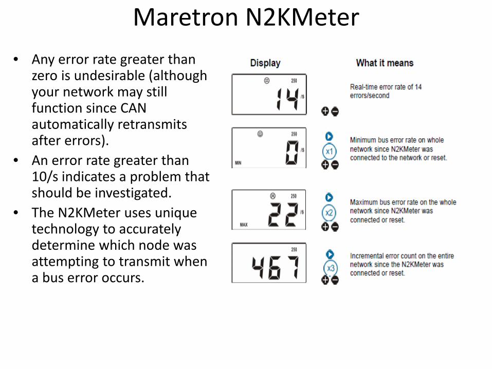
Maretron N2KMeter • Any error rate greater than
zero is undesirable (although your network may still function since CAN automatically retransmits after errors).
• An error rate greater than 10/s indicates a problem that should be investigated.
• The N2KMeter uses unique technology to accurately determine which node was attempting to transmit when a bus error occurs.