properties of coatings and applications of low pressure
TRANSCRIPT
Pure & Appl. Chem., Vol. 62, No. 9, pp. 1772-1782,1990, Printed in Great Britain. @ 1990 IUPAC
Properties of coatings and applications of low pressure plasma spray
Koichi Takeda, Michihisa Ito and Sunao Takeuchi
R&D Laboratories-1, Nippon Steel Corporation, 1618, Ida Nakahara-ku, Kawasaki, 211, JAPAN
Abstract - Based on the results obtained in our analyses, recent understandings of low pressure plasma spraying are reviewed on the following subjects; (1) computational and experimental analyses of the flow field of the plasma jet, (2) pretreatment by transferred plasma arc, (3) structures and *properties of deposits, ( 4 ) minimizing of residual stresses and ( 5 ) some possible applications.
INTRODUCTION
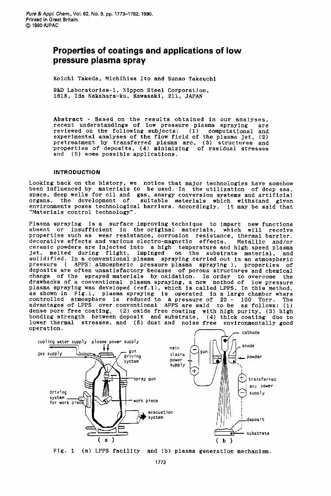
Looking back on the history, we notice that major technologies have somehow been influenced by materials to be used. In the utilization of deep sea, space, deep wells for oil and gas, energy conversion systems and artificial organs, the development of suitable materials which withstand given environments poses technological barriers. Accordingly, it may be said that "Mate r i a 1 s con t r o 1 t e c hno 1 o gy " . Plasma spraying is a surface improving technique to impart new functions absent or insufficient in the original materials, which will receive properties such as wear resistance, corrosion resistance, thermal barrier, decorative effects and various electro-magnetic effects. Metallic and/or ceramic powders are injected into a high temperature and high speed plasma jet, melted during flight, impinged on the substrate material, and solidified. In a conventional plasma spraying carried out in an atmospheric pressure ( APPS: atmospheric pressure plasma spraying 1 , properties of deposits are often unsatisfactory because of porous structures and chemical change of the sprayed materials by oxidation. In order to overcome the drawbacks of a conventional plasma spraying, a new method of low pressure plasma spraying was developed (ref.11, which is called LPPS. In this method, as shown in Fig.1, plasma spraying is operated in a large chamber where controlled atmosphere is reduced to a pressure of 20 - 100 Torr. The advantages of LPPS over conventional APPS are said to be as follows: (1) dense pore free coating, (2) oxide free coating with high purity, (3) high bonding strength between deposit and substrate, ( 4 ) thick coating due to lower thermal stresses, and ( 5 ) dust and noise free environmentally good operation.
main
( a ) ( b )
Fig. 1 (a) LPPS facility and (b) plasma generation mechanism.
1773

1774 K. TAKEDA, M. IT0 AND S. TAKEUCHI
Although these advantages have been confirmed qualitatively, more research should be made to understand the detail mechanisms which attribute to the property benefits of LPPS deposit. Recent works carried out in Nippon Steel Corporation will be described in this paper.
LPPS PLASMA JET
As contracted with APPS, LPPS jet is supersonic. Therefore the compressible effects should be taken into account on the calculation model, as well as viscous dissipative effects. Some researchers have developed the numerical models to predict the profile of the plasma jet flow (refs.2, 3, and 4). According to the numerical results, characteristics of the LPPS flow are summarized as follows. (1) High velacity flow with a reduced temperature: Thermal energy of the plasma gas is converted to kinetic one by the expansion of the volume in low pressure environment. So, the plasma gas is accelerated but cooled. ( 2 ) Expanded flame with an elongated heating zone: The reduced temperature of the jet attributes to depression of radiative heat loss from the plasma, which leads to a small decay rate of the temperature. (3) The jet with a long accelerating zone: Due to the slow temperature decay of the LPPS jet, the velocity decay is also expected to be small. That is because depression of a gas temperature induces deceleration of the flow velocity, according to the equations of state of gas and mass continuity. Typical predicted results are shown in Fig.2, where the velocity and temperature distributions in LPPS are compared with those in APPS(ref.2).
( b ) ( a )
Fig.2 Predicted flow fields along the center axis: (a) enthalpy ( thermal energy + kinetic energy ) , (b) temperature and (c) velocity.
Few works have been made to predict the momentum and heat transfer from the plasma gas to powder particles in a low pressure environment. D.Y.C. Wei and D. Apelian developed the numerical model and calculated the trajectories and thermal history of the particles by taking the non-continuum effects into account (ref.4). They revealed that the non-continuum effects have a negative influence on the momentum and heat transfer to the particles, in spite of the longer heating and accelerating zone of the LPPS jet.
In corporation with members of Nippon Steel Corp., Prof. Muraoka of Kyusyu University and his group developed the reliable measurements of the LPPS plasma by using incoherent Thompson scattering of ruby laser light by plasma electrons (ref.5). Fig.3 shows the experimental arrangement. The distributions of electron temperature and density obtained are shown in Fig.4. These results indicate that (1) electron temperature was humped between lev and 0.2eV which correspond to approximately lOOOOK and 2000K respsEt'yely, and21(2A electron density showed a similar variation from 4x10 m to 1x10 m . These humps were resulted from the existence of standing shock waves called shock diamonds. The degree of ionization in the plasma flow was estimated to be few percent. According to the L.Spitzer's formulations (ref.61, one common temperature is expected to exist among different species, because the equi-partition of the energy among various kinds of species proceeds quickly in this pressure range. However, as few recombinations of charged species occur in a plasma space, the density of the ionized species are out of equilibrium. Further studies on the effects of shock waves upon the behavior of sprayed particles are required.

Properties and applications ot low pressure plasma spray 1775
power monitor
er beam splitter
bea
monochromator
photomultipliers
Fig.3 Experimental arrangement for laser scattering diagnostics of plasma.
A
5
I .o ; \ h, r: '.
( a ) ( b ) ( C )
Fig.4 Variations of electron temperature and density along the axis of the plasma flow : (a) plasma flame, (b) electron temperature and and (c) electron density.
PRE-TREATMENT OF SUBSTRATE BY TRANSFERRED ARC
A typical LPPS facility has a transferred arc system for pre-treatment of a substrate, as shown in Fig.1. It is well-known that a transferred arc with reversed polarity has an effect to remove an oxide layer from the surface of the substrate, which works as a cathode. Prof. H . D. Steffens (ref.7) investigated the effect of the transferred arc and demonstrated that coatings with the transferred arc exhibited good adhesive qualities even if the sample was not subjected to grid blasting treatment.
The authors have also studied the cleaning effect of the arc treatment. Fig.5 shows SEM micrographs of the surface morphologies after the treatment by the transferred arc in different modes of positive and negative polarity. In both cases, the arc at a current of 37A was formed between a spray gun and a sample for a short period of 0.15sec. In a positive mode, an anode arc route was diffused over the surface of the sample, where no melting was found. On the other hand, in a negative mode, cathode arc routes were concentrated in some local spots so that melting and evaporation took place on the surface. Since most of metallic oxides have smaller work functions of emission of thermionic electrons than pure metals, the cathode spots are formed preferentially on the oxide film, which is then melted, evaporated, and removed from the surface as shown in Figs.6 and 7.

1776 K. TAKEDA, M. IT0 AND S. TAKEUCHI
Flg.8 demonstrates that the activation was resulted from the vaporization of the surface material. The melting and vaporization were desirably followed by the formation of rough surface as shown in Fig.9.
4 Fig.5 SEM micrographs of surface morphologies after transferred arc treatment: (a) positive arc mode, and (b) negative arc mode.
4 Fig.6 SEM micrographs of the surface treated by negative arc (a). and EPMA image of oxygen ( b ) .
Fig.7 The surface of the sample subjected to the negative transferred arc. 1
( b )
(b) t=O. 30sec ( c ) t-0.60sec ( a ) t=O. 15sec
;L 0 . 10 2 0 30
( a 1 ( b ) t i m e (sec 1
Fig.8 Variation of weight Fig.9 Surface morphologies and roughness: of the sample by negative (a) before, and (b) after the negative arc arc. treatment.
Properties and applications of low pressure plasma spray
Ni Co Cr Fe Mo W Y
-POWDER bal. 0.54 15.48 5.61 16.5 4.17 0.28 COATING bal. 0.56 15.56 5.53 16.0 3.56 0.28
1777
S i Mn P S 0 N C ,POWDER 0.39 0.56 0.006 0.006 0.062 0.028 0.038 COATING 0.42 0.44 0.005 0.007 0.059 0.049 0.039-
PROPERTIES OF THE LPPS DEPOSIT OF METALS AND ALLOYS
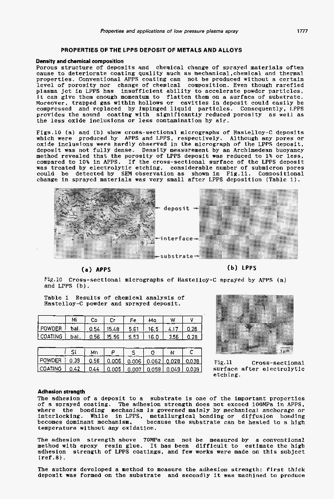
Density and chemical composition Porous structure 0-f deposits and chemical change of sprayed materia s often cause to deteriorate coating quality such as mechanica1,chemical and thermal properties. Conventional APPS coating can not be produced without a certain level of porosity nor change of chemical composition. Even though arefied plasma jet in LPPS has insufficient ability to accelerate powder particles, it can give them enough momentum to flatten them on a surface of substrate. Moreover, trapped gas within hollows or cavities in deposit could easily be compressed and replaced by impinged liquid particles. Consequently, LPPS provides the sound coating with significantly reduced porosity as well as the less oxide inclusions or less contamination by air.
Figs.10 (a) and (b) show cross-sectional micrographs of Hastelloy-C deposits which were produced by APPS and LPPS. respectively. Although any pores or oxide inclusions were hardly observed in the micrograph of the LPPS deposit, deposit was not fully dense. Density measurement by an Archimedean buoyancy method revealed that the porosity of LPPS deposit was reduced to 1% or less, compared to 10% in APPS. If the cross-sectional surface of the LPPS deposit was treated by electrolytic etching, considerable number of submicron pores could be detected by SEM observation as shown in Fig.11. Compositional change in sprayed materials was very small after LPPS deposition (Table 1).
< - - , ? ... I .
- -substrate- -
( a ) APPS ( b ) LPPS
Fig.10 Cross-sectional micrographs of Hastelloy-C sprayed by APPS (a) and LPPS (b).
Table 1 Results of chemical analysis of Hastelloy-C powder and sprayed deposit.
Fig. 11 Cross-sectional surface after electrolytic etching.
Adhesion strength The adhesion of a deposit to a substrate is one of the important properties of a sprayed coating. The adhesion strength does not exceed lOOMPa in APPS, where the bonding mechanism is governed mainly by mechanical anchorage or interlocking. While in LPPS. metallurgical bonding or diffusion bonding becomes dominant mechanism, because the substrate can be heated to a high temperature without any oxidation.
The adhesion strength above 70MPa can not be measured by a conventional method with epoxy resin glue. It has been difficult to estimate the high adhesion strength of LPPS coatings, and few works were made on this subject (ref . 8 ) .
The authors developed a method to measure the adhesion strength: first thick deposit was formed on the substrate and secondly it was machined to produce
1778 K. TAKEDA, M. IT0 AND S. TAKEUCHI
60
L O
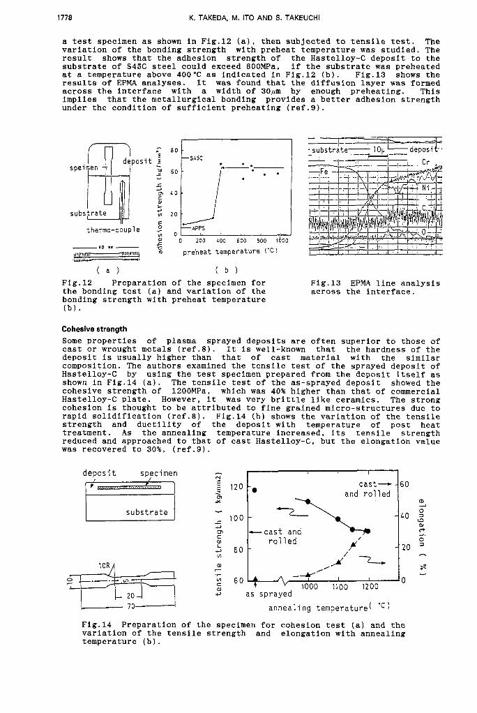
a test specimen as shown in Fig.12 (a), then subjected to tensile test. The variation of the bonding strength with preheat temperature was studied. The result shows that the adhesion strength of the Hastelloy-C deposit to the substrate of S45C steel could exceed GOOMPa, if the substrate was preheated at a temperature above 400'C as indicated in Fig.12 (b). Fig.13 shows the results of EPMA analyses. It was found that the diffusion layer was formed across the interface with a width of 30#m by enough preheating. This implies that the metallurgical bonding provides a better adhesion strength under the condition of sufficient preheating (ref.9).
-
-
cast- - 60 and rolled 0
% 0 - -\ - L o ;
+-cast and 0
- 2 0 = - Y' A' -2-
rolled
s Y
/'
A I I - 0 * ,-Y
substrate
I 1 ?. I '
E #it j
M 4 w
I I
I * O p APPS C
0 .C thermo-couple
01 I 0 200 LOO 600 800 t i 0 0
preheat temperature ('C)
( a ) ( b ) Fig.12 Preparation of the specimen for the bonding test (a) and variation of the bonding strength with preheat temperature (b).
Fig.13 EPMA line analysis across the interface.
Cohesive strength Some properties of plasma sprayed deposits are often superior to those of cast or wrought metals (ref.8). It is well-known that the hardness of the deposit is usually higher than that of cast material with the similar composition. The authors examined the tensile test of the sprayed deposit of Hastelloy-C by using the test specimen prepared from the deposit itself as shown in Fig.14 (a). The tensile test of the as-sprayed deposit showed the cohesive strength of 1200MPa, which was 40% higher than that of commercial Hastelloy-C plate. However, it was very brittle like ceramics. The strong cohesion is thought to be attributed to fine grained micro-structures due to rapid solidification (ref.8). Fig.14 (b) shows the variation of the tensile strength and ductility of the deposit with temperature of post heat treatment. A s the annealing temperature increased, its tensile strength reduced and approached to that of cast Hastelloy-C, but the elongation value was recovered to 3096, (ref.9).
N : 120 . m Y
0, C W
$ 8 0 v)
W - 'F
6 0 W c,
70-
Fig.14 Preparation of the specimen for cohesion test (a) and the variation of the tensile strength and elongation with annealing temperature (b).

Properties and applicarions of low pressure plasma spray 1779
commercial p l a t e LPPS coa t ing
Corrosionlerosion resistance The most established application of LPPS is now to the coating on gas turbine air foils. MCrAlY alloys are usually used as hot corrosion resistant materials, which provide active elements to the surface for the formation of a tight protective oxide scale (ref.lO,ll). However, few applications have been made against other types of corrosion and erosion. In order to investigate the corrosion resistance of the LPPS coatings against the highly corrosive environment such as that in a deep well for the production of oil and gas, Hastelloy-C coating on carbon steel substrate (SCM435) was examined by means of autoclave test. As the references cast Hasetelloy-C and Hastelloy-C coating on steel substrate by APPS were also examined. The test was carried out by using 20% NaCl H S and Cog environment with partial pressures of PHgS = lOOatm and Pco l80atm and at a temperature of 250°C. Table 2 ind cates the results. ieciuse of the reduced porosity, the corrosion resistance of the LPPS specimen was comparable with that of the cast Hastelloy-C, while conventional APPS specimen had the very poor resistance. These results indicate that LPPS coating has a high potential for the application to key components used in severe corrosive environment without any post treatment.
solution in
APPS coa t ing
cor ros ion r a t e ( mgldm2lday 1 1 1.9 2 . 3 - 2.6 1 - 500
the main factors to prevent machinery or
are many types of erosion, and some plants from stable operations. There -
CONTROL OF INTERNAL STRESS IN THE COATING
One of the significant advantages of plasma spraying is in a high rate of deposition, compared with other dry processes. However, plasma spraying, even LPPS, often fails to build up thick coating, due to the accumulation of internal stress, which leads to the peeling or cracking of the deposit, as illustrated in Fig.16. Residual stress in the coating is caused from the difference in the shrinkage between a deposit and a substrate, after the cooling of the coated material. There are two ways to overcome this problem. One of them is to insert a third material to reduce the interfacial stress due to the difference of thermal expansion coefficient between the top coat and the substrate. Not only such undercoating of the third material but also graded coating is often used, where the mixing rate of the sprayed materials is varied.
Stell i te N o 6 (bulk)

1780 K. TAKEDA, M. IT0 AND S. TAKEUCHI
The other way is to control the temperature of the substrate during spraying. Roughly saying, the deposit material has the thermal history from its melting temperature to a room temperature, while the substrate has that from a certain controlled temperature to a room temperature. The difference of the shrinkage between coating and substrate can be expressed as a function of the controlled temperature of the substrate, as well as the thermal properties and mechanical properties of the materials used.
TENS ION COMPRESSION Fig.16 Schematic illustration of residual stress and sample deformation.
The variation of the residual stress with the substrate temperature was calculated from the mathematical model developed by authors. Fig.16 shows the calculated residual stress in Mo deposit on carbon steel substrate. The optimum temperature to produce the stress-free coating is predicted by this calculation. Experimental study confirms this prediction qualitatively.
Fig.17 Effect of the substrate b temperature on residual stress in 500 1000 1500 2000 the deposit. Substrate temperature (K)
APPLICATIONS
LPPS has been developed to form the oxidation-resistance coatings for hot-section components of gas turbine of the aircraft. MCrAlY type alloys have been overlayed to obtain long-life and high performance engines. This coating technique has been well established, however. other types of applications are under development now. Some attempts carried out in our laboratories will be described in this section.
Anti-wear guiding roller (ref. 13) Guiding rollers in hot strip mill are swinging of stainless steel sheet whose temperature is about 1000°C (Fig.18). In order to improve the resistance against abrasive wear and scale-adhering, cermet of Cr2C /NiCr mixture was coated on the rollers. High hardness of Cr2C3 is expectea to be kept in high temperature, and addition of NiCr makes it possible to form thick deposit more than lmm. The LPPS-coated guide rollers
used for preventing from
SUS Strip
-m F,-F'l F5 F.5 m-
Hot strip mill at Muroran Works
Guide Roller (24 pieces/Line) Dimensions ;
4140 ODxl808 (2408 )
( a ) ( b ) Fig.18 Location of guide rollers in hot strip mill (a) and the out look (b).

Properties and applications of low pressure plasma spray 1781
started to be used in July 1986, and even now are working without any damages. This means that the life time of the guiding roller is elongated at least a hundred times. Manufacturing cost of the LPPS-coated guide rollers are only seven times higher than conventional rollers. That means so excellent advantage is proved.
Anti-erosion steam turbine blade In steam power plants, drain erosion occurs in edges of turbine blades which are impinged by water drops condensing from the steam vapor with high speed. Although, Satellite plates are often brazed on the blade edges to prevent them from drain erosion, repair of the blades is required every several years. As mentioned above, Stellite deposited by LPPS showed excellent erosion resistance, so the coating is expected to elongate the life of the blades. In order to check the drain erosion resistance, the specimens covered with Stellite by LPPS were examined by rotating arm test, where oil drops were sprayed at a high velocity of 700m/sec or more against the moving specimen. Excellent performance of the deposit was shown in Fig.19. Although further works are necessary, this result indicates the high potential of LPPS coating on the steam turbine blades.
% 250. - Stellite plate V * Stellite deposit
0
- \ E" 200 - V
$ 150- -
* Stellite deposit \ E" 200 V I / I
$ 1501 -
- - 0 5 10 15 20 25 30 0 50 100 150 200 250
t ime ( h o u r ) temperature ( K )
Fig.19 Erosion results by using a Fig.20 Variation of resistivity of rotating y m test. Weight loss was 0.34mg/cm /hr for the LPPS deposit and 9.34mg/cm2/hr for a Stellite plate.
YBCO deposit with temperature.
Fabrication of high temperature superconducting film Since the discovery of high temperature superconducting oxides, many trials have been undertaken to produce the coatings of the superconductor by means of plasma spraying techniques. These spray coatings offer the advantages of applicability to a wide range of substrate materials and flexibility in spraying a large range of geometries and thicknesses. Fig.20 shows the typical resistive transition curve of Y-Ba-Cu-0 deposited by LPPS with a thickness of 0.lmm on SUS304 substrate. The powder for the LPPS spraying was prepared by mixing Y 03, BaC03 and CuO in the correct ratios, and reacted around 900°C for 8-34 hours. The reacted material was then reground to form powder suitable for the spray feeders. The as-sprayed coatings were not superconducting, but a post-annealing restored the superconducting properties. Much works should be done for further improvement of the superconducting properties of the deposit such as transition temperature and critical current density, and development of the formation of patterned structures.
Near net shape forming Plasma spraying technology is recognized to be a competitive or alternative route to a conventional powder processing which consists of powder compaction and sintering(ref.8). The characteristics of LPPS mentioned above permit the incremental build up of near net shape components with high density (pore-free) and property benefits due to rapid solidification. It could provide not only bulky components but also thin walled ones in few simple processes. Fig.21 shows a free standing tungsten tube with screw thread inside, which was obtained by spraying tungsten over copper substrate with screw outside and then removing the substrate. Near net shape forming by LPPS is a promising process to produce composite structures.

1782 K. TAKEDA, M. IT0 AND S. TAKEUCHI
rFig.21 Near Net Shape Tube formed by LPPS: (a) W tube with screw, (b) Mo and (c) Ti tube.
CONCLUDING REMARKS
Low pressure plasma spraying has some process advantages, and the property benefits of the coating seem to promise its future of applications. However, because .of high cost compared to other conventional spray processing, its applications strongly depend on the availability and performance.
To optimize the spraying process and improve the quality of the deposits, further fundamental studies on pre-treatment of substrates, melting of particles, solidification phenomena, and post treatment are necessary.
In this paper, the authors mentioned little about graded coating and reactive coating, but basic researches and engineering developments in these fields have been done by many researchers to open up new applications.
REFERENCES
1. E.Muehlberger, 7th Int.Therma1 Spray Conf.. 245 (1974) 2. K.Takeda, K.Hayashi and T.Ohashi, Proc. ISPC-7, 848 (1985) 3. D.Wei, D.Apelian and B. Farouk, Proc. ISPC-7, 810 (1985) 4. D.Wei, B.Farouk and D.Apelian. J . Heat Transfer, 971 (1987) 5. R.Hidaka, T.Ooki, K.Takeda, K.Kondo. H.Kanda, K,Uchino, Y.Matsuda,
K.Muraoka, M.Akazaki, Japanese J . Appl. Phys.. 26, L1724 (1987) 6. L.Spitzer, Physics of Fully Ionized Gases. (Intersience, NewYork, 1962) 7. H.D.Steffens, Proc. 9th Int. Thermal Spray Conf., 420 (1980) 8. M.Jackson, J.Rairden, J.Smith and R Smith, J. Metals, 33, 23 (1981) 9. K.Hayashi, M.Ito, A.Nogami and K.Takeda, Proc. ISPC-8. 1940 (1987) 10. A.Missbacher and W.Track. Proc. 8th Int. Thermal Spray Conf., 25 (1977) 11. R.W.Smith, W.F.Schilling and H.M.Fox, Proc. 9th Int. Thermal Spray Conf.,
12. P.C.Wolf and F.N.Longo, Proc. 9th Int. Thermal Spray Conf., 187 (1980) 13. H.Takigawa, M.Hirata, M.Koga, M.Ito and K.Takeda, Proc. 16th Int. Conf.
334 (1980)
Metall. Coat. (1989), to be published.