propulsion systems design - dave akin's web site
TRANSCRIPT

Rocket PropulsionLaunch and Entry Vehicle Design
U N I V E R S I T Y O FMARYLAND
Propulsion Systems Design
• Rocket engine basics• Solid rocket motors• Liquid rocket engines
• Monopropellants• Bipropellants• Propellant feed systems
• Hybrid rocket engines• Auxiliary propulsion systems
© 2004 David L. Akin - All rights reservedhttp://spacecraft.ssl.umd.edu

Rocket PropulsionLaunch and Entry Vehicle Design
U N I V E R S I T Y O FMARYLAND
Thermal Rocket Exhaust Velocity• Exhaust velocity is
where
€
Ve =2γγ −1
ℜT0M
1− pe
p0
γ −1γ
€
M ≡ average molecular weight of exhaust
€
ℜ ≡ universal gas const .= 8314.3 Joulesmole°K
€
γ ≡ ratio of specific heats ≈1.2

Rocket PropulsionLaunch and Entry Vehicle Design
U N I V E R S I T Y O FMARYLAND
Ideal Thermal Rocket Exhaust Velocity• Ideal exhaust velocity is
• This corresponds to an ideally expanded nozzle
• All thermal energy converted to kinetic energy of exhaust
• Only a function of temperature and molecular weight!
€
Ve =2γγ −1
ℜT0M

Rocket PropulsionLaunch and Entry Vehicle Design
U N I V E R S I T Y O FMARYLAND
Thermal Rocket Performance• Thrust is
• Effective exhaust velocity
• Expansion ratio
€
T = ˙ m Ve + pe − pamb( )Ae
€
T = ˙ m c ⇒ c = Ve + pe − pamb( ) Ae
˙ m
€
AtAe
=γ +12
1γ −1 pe
p0
1γ γ +1
γ −11− pe
p0
γ −1γ
€
Isp =cg0

Rocket PropulsionLaunch and Entry Vehicle Design
U N I V E R S I T Y O FMARYLAND
Nozzle Design• Pressure ratio p0/pe=100 (1470 psi-->14.7 psi)
Ae/At=11.9
• Pressure ratio p0/pe=1000 (1470 psi-->1.47 psi)Ae/At=71.6
• Difference between sea level and ideal vacuum Ve
• Isp,vacuum=455 sec --> Isp,sl=333 sec
€
VeVe,ideal
= 1− pep0
γ −1γ

Rocket PropulsionLaunch and Entry Vehicle Design
U N I V E R S I T Y O FMARYLAND
Solid Rocket Motor
From G. P. Sutton, Rocket Propulsion Elements (5th ed.) John Wiley and Sons, 1986

Rocket PropulsionLaunch and Entry Vehicle Design
U N I V E R S I T Y O FMARYLAND
Solid Propellant Combusion Characteristics
From G. P. Sutton, Rocket Propulsion Elements (5th ed.) John Wiley and Sons, 1986

Rocket PropulsionLaunch and Entry Vehicle Design
U N I V E R S I T Y O FMARYLAND
Solid Grain Configurations
From G. P. Sutton, Rocket Propulsion Elements (5th ed.) John Wiley and Sons, 1986

Rocket PropulsionLaunch and Entry Vehicle Design
U N I V E R S I T Y O FMARYLAND
Short-Grain Solid Configurations
From G. P. Sutton, Rocket Propulsion Elements (5th ed.) John Wiley and Sons, 1986

Rocket PropulsionLaunch and Entry Vehicle Design
U N I V E R S I T Y O FMARYLAND
Advanced Grain Configurations
From G. P. Sutton, Rocket Propulsion Elements (5th ed.) John Wiley and Sons, 1986

Rocket PropulsionLaunch and Entry Vehicle Design
U N I V E R S I T Y O FMARYLAND
Liquid Rocket Engine

Rocket PropulsionLaunch and Entry Vehicle Design
U N I V E R S I T Y O FMARYLAND
Liquid Propellant Feed Systems

Rocket PropulsionLaunch and Entry Vehicle Design
U N I V E R S I T Y O FMARYLAND
Pressurization System Analysis
Pg0, Vg
PL, VL
Pgf, Vg
PL, VL
Adiabatic Expansion of Pressurizing Gas
Initial Final
€
pg,0Vgγ = pg, fVg
γ + plVlγ
Known quantities:
Pg,0=Initial gas pressure
Pg,f=Final gas pressure
PL=Operating pressure of propellant tank(s)
VL=Volume of propellant tank(s)
Solve for gas volume Vg
Rocket PropulsionLaunch and Entry Vehicle Design
U N I V E R S I T Y O FMARYLAND
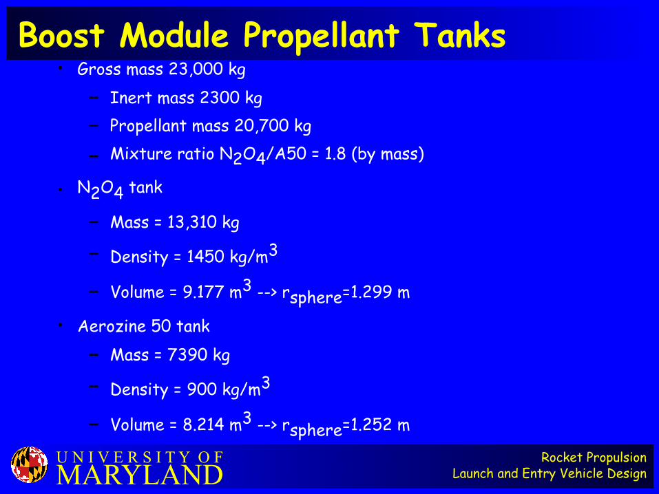
Boost Module Propellant Tanks• Gross mass 23,000 kg
– Inert mass 2300 kg– Propellant mass 20,700 kg
– Mixture ratio N2O4/A50 = 1.8 (by mass)
• N2O4 tank
– Mass = 13,310 kg
– Density = 1450 kg/m3
– Volume = 9.177 m3 --> rsphere=1.299 m
• Aerozine 50 tank– Mass = 7390 kg
– Density = 900 kg/m3
– Volume = 8.214 m3 --> rsphere=1.252 m

Rocket PropulsionLaunch and Entry Vehicle Design
U N I V E R S I T Y O FMARYLAND
Boost Module Main Propulsion• Total propellant volume VL = 17.39 m3
• Assume engine pressure p0 = 250 psi
• Tank pressure pL = 1.25*p0 = 312 psi
• Final GHe pressure pg,f = 75 psi + pL = 388 psi
• Initial GHe pressure pg,0 = 4500 psi
• Conversion factor 1 psi = 6892 Pa• Ratio of specific heats for He = 1.67
• Vg = 3.713 m3
• Ideal gas: T=300°K -->
ρ=49.7 kg/m3 (300 psi = 31.04 MPa) MHe=185.1 kg
€
4500 psi( )Vg1.67 = 388 psi( )Vg
1.67 + 312 psi( ) 17.39 m 3( )1.67
€
ρHe =pg,0M ℜT0

Rocket PropulsionLaunch and Entry Vehicle Design
U N I V E R S I T Y O FMARYLAND
Space Shuttle OMS Engine
From G. P. Sutton, Rocket Propulsion Elements (5th ed.) John Wiley and Sons, 1986

Rocket PropulsionLaunch and Entry Vehicle Design
U N I V E R S I T Y O FMARYLAND
Turbopump Fed Liquid Rocket Engine
From G. P. Sutton, Rocket Propulsion Elements (5th ed.) John Wiley and Sons, 1986

Rocket PropulsionLaunch and Entry Vehicle Design
U N I V E R S I T Y O FMARYLAND
Sample Pump-fed Engine Cycles
From G. P. Sutton, Rocket Propulsion Elements (5th ed.) John Wiley and Sons, 1986

Rocket PropulsionLaunch and Entry Vehicle Design
U N I V E R S I T Y O FMARYLAND
Gas Generator Cycle Engine
From G. P. Sutton, Rocket Propulsion Elements (5th ed.) John Wiley and Sons, 1986

Rocket PropulsionLaunch and Entry Vehicle Design
U N I V E R S I T Y O FMARYLAND
SSME Engine Cycle
From G. P. Sutton, Rocket Propulsion Elements (5th ed.) John Wiley and Sons, 1986

Rocket PropulsionLaunch and Entry Vehicle Design
U N I V E R S I T Y O FMARYLAND
Liquid Rocket Engine Cutaway
From G. P. Sutton, Rocket Propulsion Elements (5th ed.) John Wiley and Sons, 1986

Rocket PropulsionLaunch and Entry Vehicle Design
U N I V E R S I T Y O FMARYLAND
H-1 Engine Injector Plate

Rocket PropulsionLaunch and Entry Vehicle Design
U N I V E R S I T Y O FMARYLAND
Injector Concepts
From G. P. Sutton, Rocket Propulsion Elements (5th ed.) John Wiley and Sons, 1986

Rocket PropulsionLaunch and Entry Vehicle Design
U N I V E R S I T Y O FMARYLAND
Solid Rocket Nozzle (Heat-Sink)
From G. P. Sutton, Rocket Propulsion Elements (5th ed.) John Wiley and Sons, 1986

Rocket PropulsionLaunch and Entry Vehicle Design
U N I V E R S I T Y O FMARYLAND
Ablative Nozzle Schematic
From G. P. Sutton, Rocket Propulsion Elements (5th ed.) John Wiley and Sons, 1986

Rocket PropulsionLaunch and Entry Vehicle Design
U N I V E R S I T Y O FMARYLAND
Active Chamber Cooling Schematic
From G. P. Sutton, Rocket Propulsion Elements (5th ed.) John Wiley and Sons, 1986

Rocket PropulsionLaunch and Entry Vehicle Design
U N I V E R S I T Y O FMARYLAND
Boundary Layer Cooling Approaches
From G. P. Sutton, Rocket Propulsion Elements (5th ed.) John Wiley and Sons, 1986

Rocket PropulsionLaunch and Entry Vehicle Design
U N I V E R S I T Y O FMARYLAND
Hybrid Rocket Schematic
From G. P. Sutton, Rocket Propulsion Elements (5th ed.) John Wiley and Sons, 1986

Rocket PropulsionLaunch and Entry Vehicle Design
U N I V E R S I T Y O FMARYLAND
Hybrid Rocket Combustion
From G. P. Sutton, Rocket Propulsion Elements (5th ed.) John Wiley and Sons, 1986
Rocket PropulsionLaunch and Entry Vehicle Design
U N I V E R S I T Y O FMARYLAND
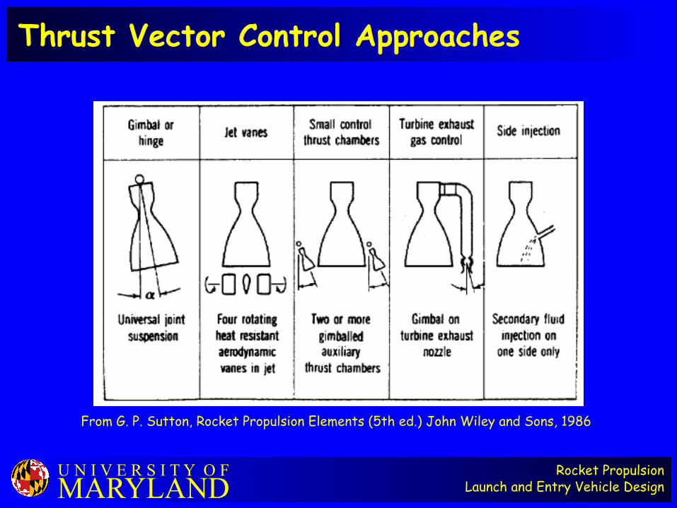
Thrust Vector Control Approaches
From G. P. Sutton, Rocket Propulsion Elements (5th ed.) John Wiley and Sons, 1986

Rocket PropulsionLaunch and Entry Vehicle Design
U N I V E R S I T Y O FMARYLAND
Apollo Reaction Control System Thrusters

Rocket PropulsionLaunch and Entry Vehicle Design
U N I V E R S I T Y O FMARYLAND
Space Shuttle Primary RCS Engine
From G. P. Sutton, Rocket Propulsion Elements (5th ed.) John Wiley and Sons, 1986
Rocket PropulsionLaunch and Entry Vehicle Design
U N I V E R S I T Y O FMARYLAND
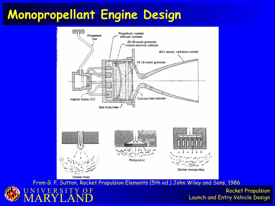
Monopropellant Engine Design
From G. P. Sutton, Rocket Propulsion Elements (5th ed.) John Wiley and Sons, 1986

Rocket PropulsionLaunch and Entry Vehicle Design
U N I V E R S I T Y O FMARYLAND
Cold-gas Propellant Performance
From G. P. Sutton, Rocket Propulsion Elements (5th ed.) John Wiley and Sons, 1986
Rocket PropulsionLaunch and Entry Vehicle Design
U N I V E R S I T Y O FMARYLAND
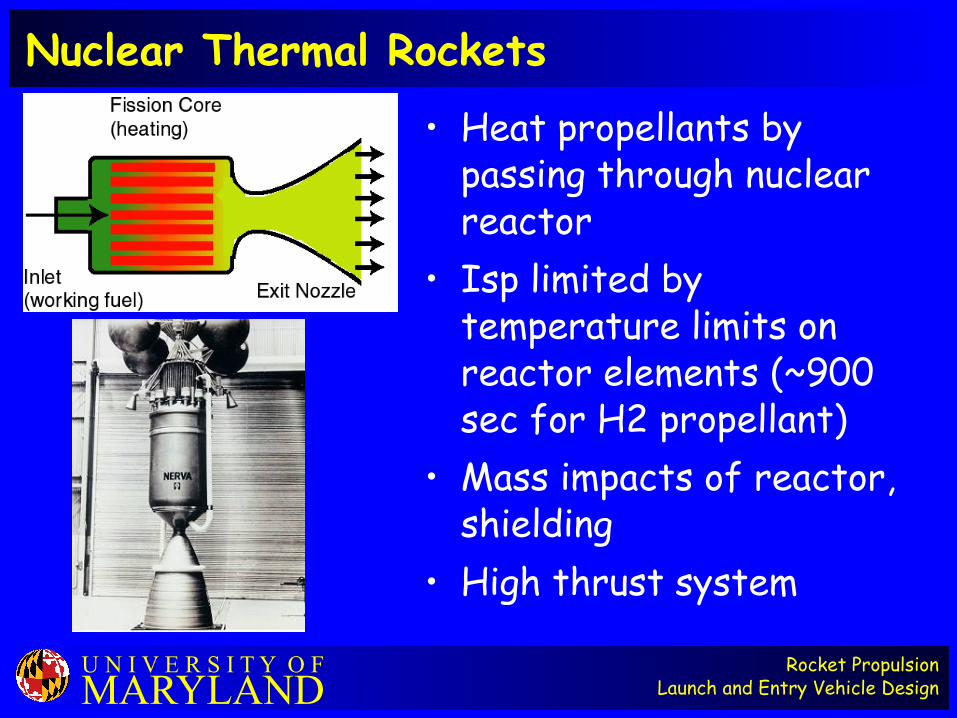
Nuclear Thermal Rockets
• Heat propellants by passing through nuclear reactor
• Isp limited by temperature limits on reactor elements (~900 sec for H2 propellant)
• Mass impacts of reactor, shielding
• High thrust system