protection and coordination for solar sites on the ... · protection and coordination for solar...
TRANSCRIPT

Protection and Coordination for Solar Sites on the Distribution Power System
Luke P. Booth
Application Engineer – Protection
Schweitzer Engineering Labs, Inc.
• The Impacts of DG on feeder protection and the need
for communications assisted tripping schemes
• Direct Transfer Tripping (DTT) Communication Scheme
• Mirror Bits
• Direct Fiber Attributes
Overview

• Unintentional islanding
• Increased fault duty
• Relay desensitization
• Nuisance tripping
• Automatic reclosing
DG Impact on Distribution Feeders
• Occurs when portion of area EPS and DR become
electrically isolated from rest of area EPS and DR
continues to energize island
• Should be avoided for two major reasons
• There is potential for negative effects on voltage, frequency,
and power quality
• Islanded generator complicates both automatic reclosing
and manual switching
Unintentional Islanding

• Is caused by addition of generating sources and
rotating machinery of considerable size
• Affects capability of equipment to carry and interrupt
fault currents
• Requires both local and area EPS equipment ratings
to be reevaluated
Increased Fault Duty

• Available short-circuit current increases with
addition of DR
• Short-circuit current splits between substation and DR
• Substation short-circuit contribution can be significantly
reduced when compared with value before
addition of DR
Relay Desensitization
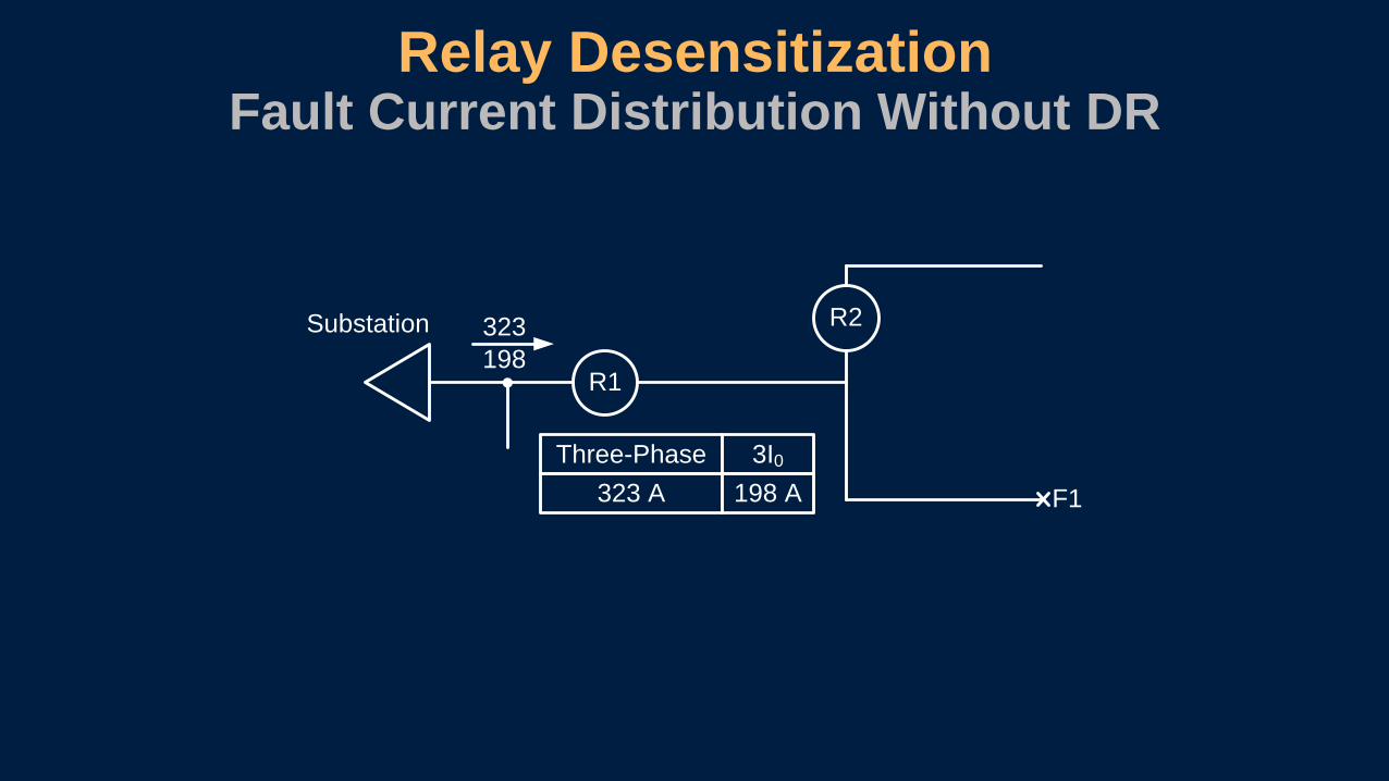
Relay DesensitizationFault Current Distribution Without DR
323
R1
R2Substation
F1
Three-Phase 3I0
323 A 198 A
198

Relay DesensitizationFault Current Distribution With DR
199
R1
R2Substation
F1Three-Phase 3I0
199 A 24 A
24
200
246
Substation
Three-Phase 3I0
200 A 246 A
DR 399
270
DR
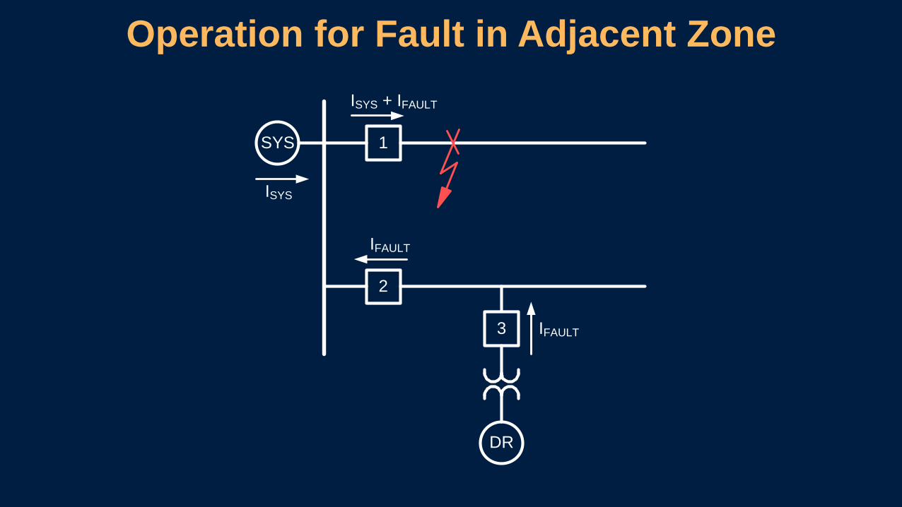
Operation for Fault in Adjacent Zone
SYS
DR
1
2
3
ISYS
ISYS + IFAULT
IFAULT
IFAULT
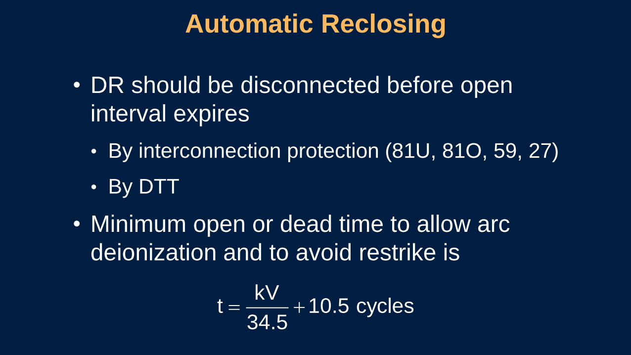
• DR should be disconnected before open
interval expires
• By interconnection protection (81U, 81O, 59, 27)
• By DTT
• Minimum open or dead time to allow arc
deionization and to avoid restrike is
Automatic Reclosing
= +kV
t 10.5 cycles34.5

• Feeder and bus are in synchronism
• Utility bus is hot and line is dead
Automatic ReclosingClose Permissives
DR
Utility
Bus
Live Bus /
Dead Line or
Synchronism
3
3
Multifunction
Relay
C T
1
Temporary
Fault
Nonconventional Power Sources Under Fault Conditions
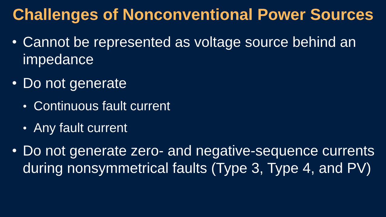
• Cannot be represented as voltage source behind an
impedance
• Do not generate
• Continuous fault current
• Any fault current
• Do not generate zero- and negative-sequence currents
during nonsymmetrical faults (Type 3, Type 4, and PV)
Challenges of Nonconventional Power Sources
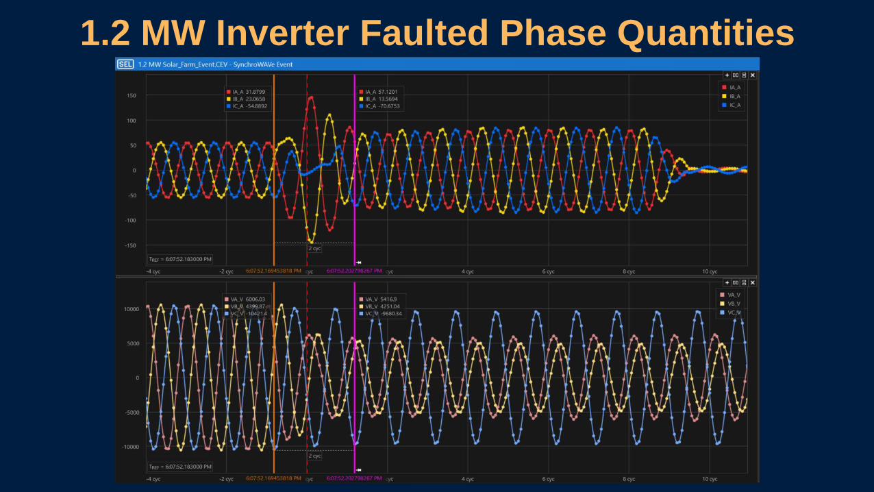
1.2 MW Inverter Faulted Phase Quantities
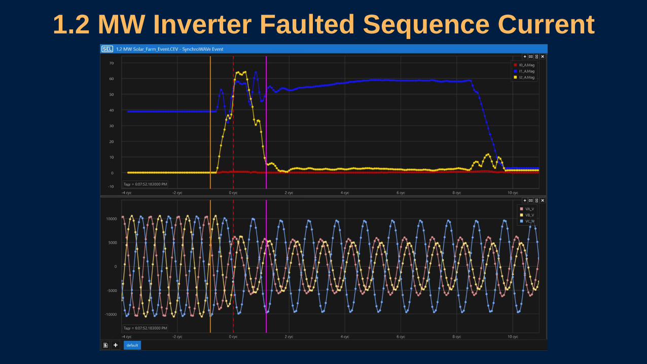
1.2 MW Inverter Faulted Sequence Current
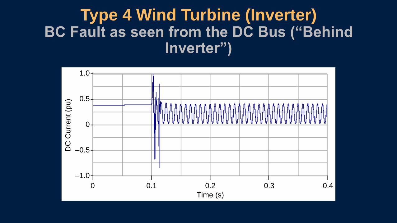
Type 4 Wind Turbine (Inverter)BC Fault as seen from the DC Bus (“Behind
Inverter”)
0.5
–0.5
0
0 0.1 0.2 0.3 0.4
DC
Cu
rre
nt (p
u)
Time (s)
–1.0
1.0

• Traditional Overcurrent Elements may not operate
• Fault currents typically reach 1.5 to 1.7 times the inverter’s
maximum load current at the moment the fault occurs (fault
inception).
• 1-4 ms after fault inception, the inverter will continue to
provide fault current at approximately 120% of nominal load
current
Consequences of Nonconventional Power Source Behavior During Faults

• Directional Elements no longer work as expected
• The inverter produces no sequence currents.
• The microprocessor relay does not have a polarizing
quantity to accurately declare a fault direction.
Consequences of Nonconventional Power Source Behavior During Faults

Wind or PV
Farm
Conventional
Source
Fault Behavior Summary by Source
Anti-Islanding ProtectionIEEE 1547 general requirements to be met at
point of common coupling (PCC)

Changed in 1547a-2014
DR Response to Voltage Excursions
Voltage Range (% of base voltage) Clearing Time (s) Clearing Time: Adjustable
Up To and Including (s)
V < 45 0.16 0.16
45 ≤ V < 60 1.00 11
60 ≤ V < 88 2.00 21
110 < V < 120 1.00 13
V ≥ 120 0.16 0.16
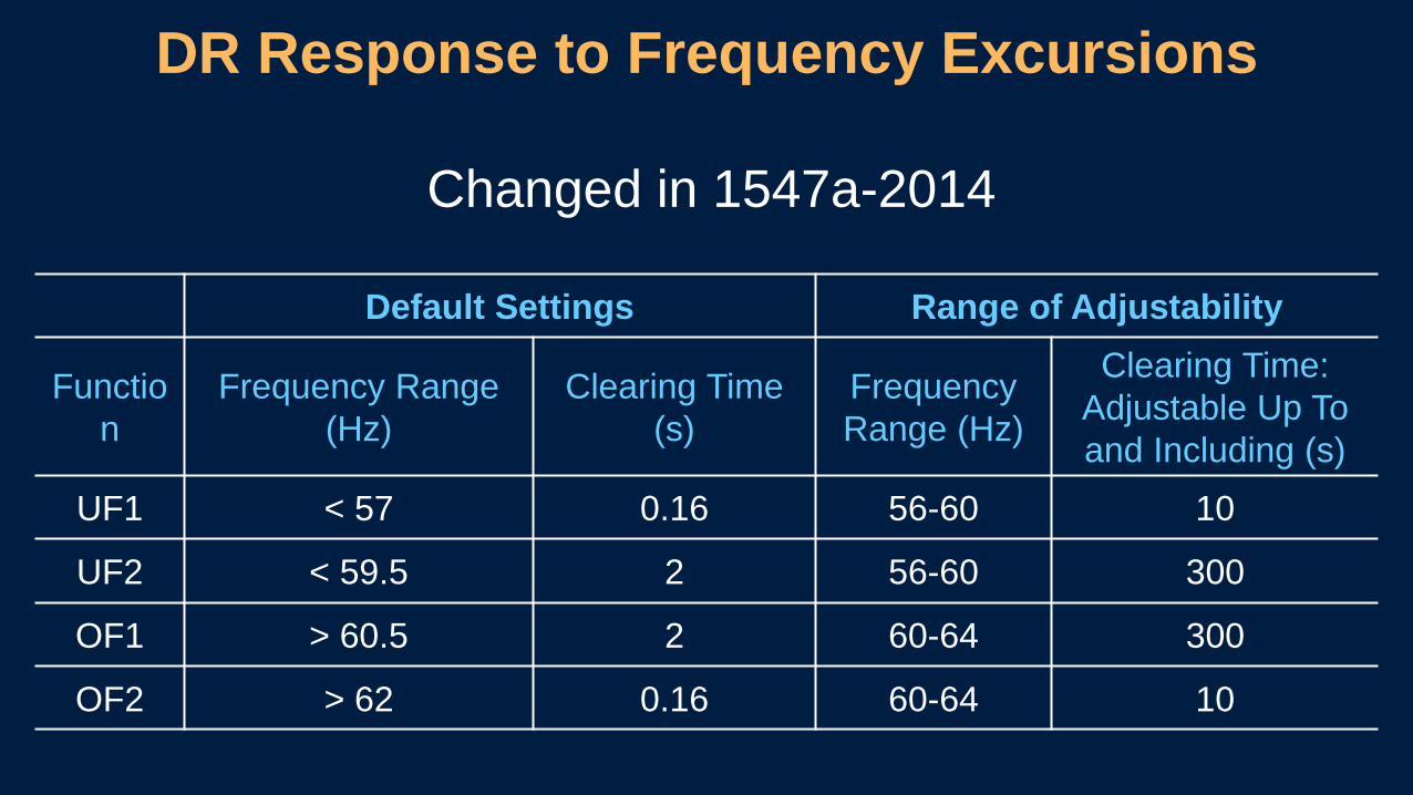
DR Response to Frequency Excursions
Changed in 1547a-2014
Default Settings Range of Adjustability
Functio
n
Frequency Range
(Hz)
Clearing Time
(s)
Frequency
Range (Hz)
Clearing Time:
Adjustable Up To
and Including (s)
UF1 < 57 0.16 56-60 10
UF2 < 59.5 2 56-60 300
OF1 > 60.5 2 60-64 300
OF2 > 62 0.16 60-64 10
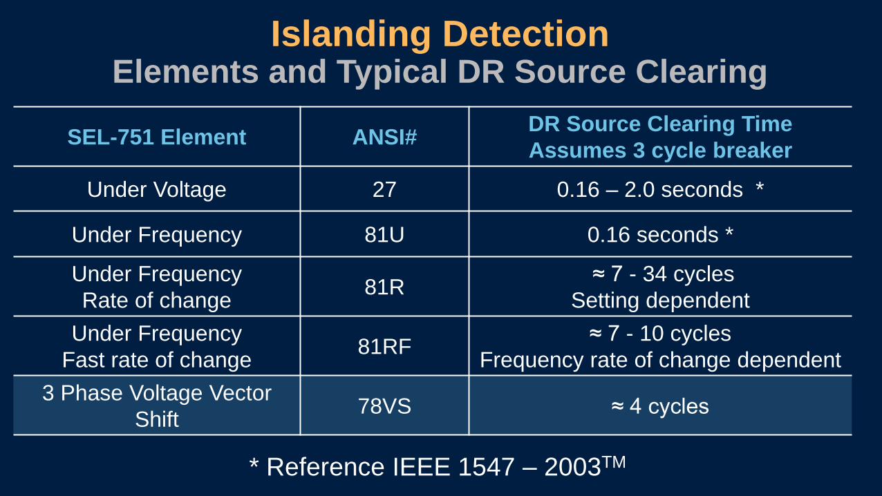
Islanding Detection Elements and Typical DR Source Clearing
SEL-751 Element ANSI#DR Source Clearing Time
Assumes 3 cycle breaker
Under Voltage 27 0.16 – 2.0 seconds *
Under Frequency 81U 0.16 seconds *
Under Frequency
Rate of change 81R
≈ 7 - 34 cycles
Setting dependent
Under Frequency
Fast rate of change81RF
≈ 7 - 10 cycles
Frequency rate of change dependent
3 Phase Voltage Vector
Shift78VS ≈ 4 cycles
* Reference IEEE 1547 – 2003TM
Possible Solutions:Fast Rate of Change 81RF Element
Vector Shift 78VS ElementNegative Sequence Overvoltage (59Q)

Fast Rate of Change of Frequency
Definitions
• Change in Frequency (FREQ-FNOM)• Slip of the frequency
• Speed of the Change of Frequency (FREQ-FNOM)/s• Acceleration
In words, “Not only does the frequency have to change
by a certain value but it also has to change at a certain
rate.”

Fast Rate of Change of Frequency
Islanded
Connected
Acceleration
Slip Frequency0
0
Islanded
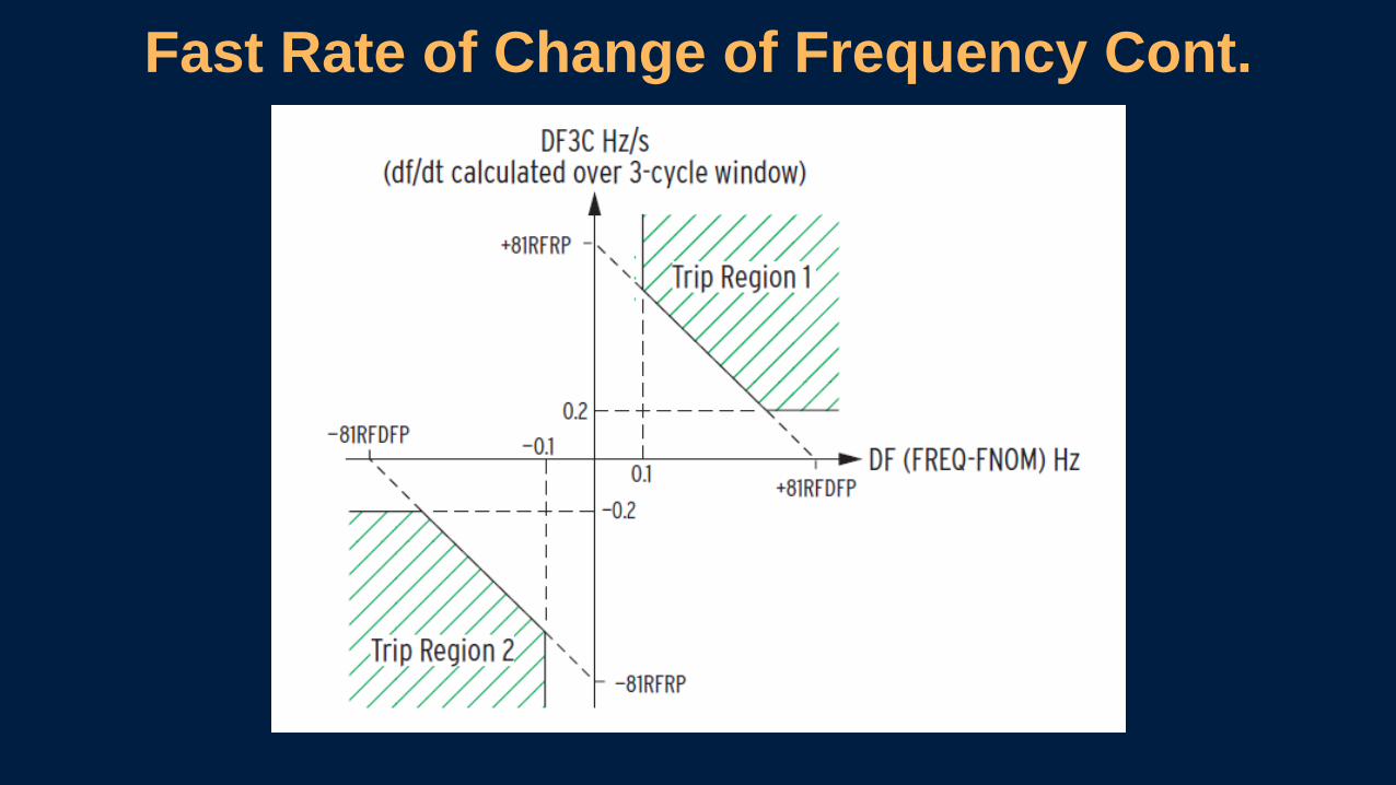
Fast Rate of Change of Frequency Cont.
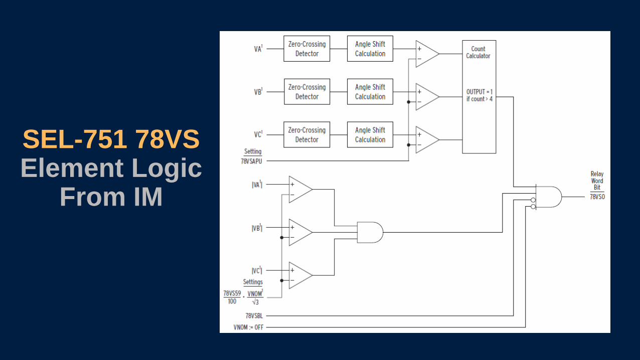
SEL-751 78VSElement Logic
From IM
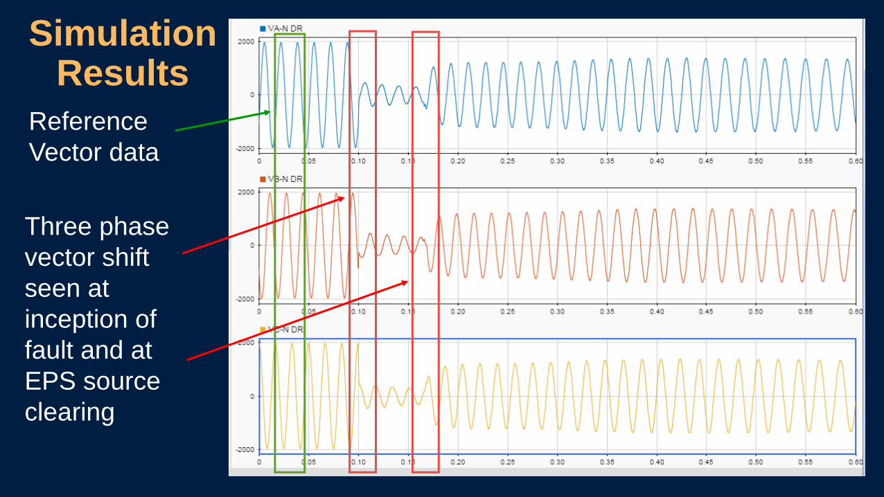
Simulation Results
Three phase
vector shift
seen at
inception of
fault and at
EPS source
clearing
Reference
Vector data
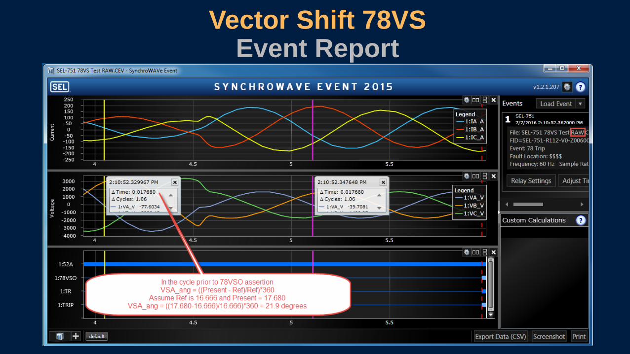
Vector Shift 78VSEvent Report

• Fastest Method of islanding detection
• Relies total on DR source voltage monitoring
• Includes under voltage supervision
Advantages of the 78VS element
Disadvantages of the 78VS element
• Requires 20% loading increase at islanding
• Requires system studies for secure settings
• Requires DR close circuit monitoring

Islanding Detection Elements and Typical DR Source Clearing
SEL-751 Element ANSI#DR Source Clearing Time
Assumes 3 cycle breaker
Under Voltage 27 0.16 – 2.0 seconds *
Under Frequency 81U 0.16 seconds *
Under Frequency
Rate of change 81R
≈ 7 - 34 cycles
Setting dependent
Under Frequency
Fast rate of change81RF
≈ 7 - 10 cycles
Frequency rate of change dependent
3 Phase Voltage Vector
Shift78VS ≈ 4 cycles
* Reference IEEE 1547 – 2003TM

Faulted Phase and Sequence Voltages of the Inverter
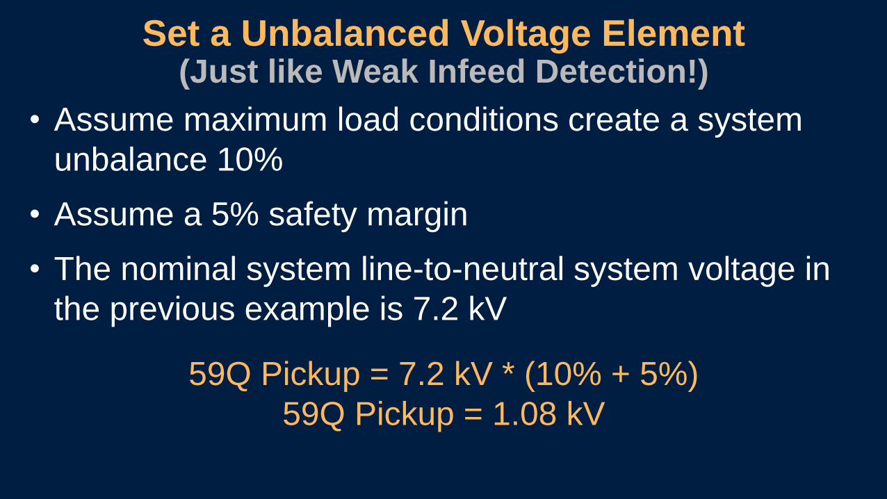
Set a Unbalanced Voltage Element(Just like Weak Infeed Detection!)
• Assume maximum load conditions create a system
unbalance 10%
• Assume a 5% safety margin
• The nominal system line-to-neutral system voltage in
the previous example is 7.2 kV
59Q Pickup = 7.2 kV * (10% + 5%)
59Q Pickup = 1.08 kV

Evaluating Weak Infeed For the Inverter Fault

Communications Assisted Tripping
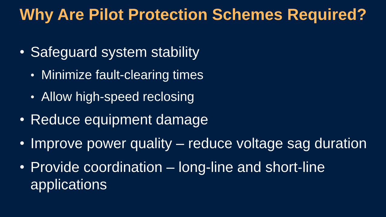
• Safeguard system stability
• Minimize fault-clearing times
• Allow high-speed reclosing
• Reduce equipment damage
• Improve power quality – reduce voltage sag duration
• Provide coordination – long-line and short‐line
applications
Why Are Pilot Protection Schemes Required?

• DTT
• POTT
• PUTT
• DCB
• DCUB
Types of Directional Comparison Protection Schemes

DTT Scheme
Relay 1 Relay 2
Transmitter
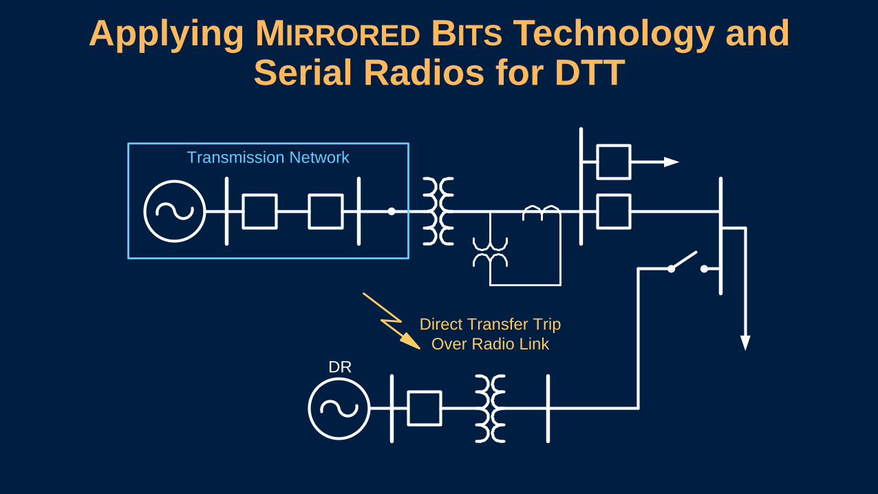
Applying MIRRORED BITS Technology and Serial Radios for DTT
DR
Transmission Network
Direct Transfer Trip
Over Radio Link

Mirrored Bits Communications

Mirrored Bits CommunicationsTransmit “Mirrored” to Receive
Relay 1 Relay 2
TRANSMIT
TMB1
TMB2...
TMB8
RMB1
RMB2...
RMB8
TMB1
TMB2...
TMB8
RMB1
RMB2...
RMB8
RECEIVE
TRANSMIT
RECEIVE
0
...
0
0
0
...
0
0
1
0
0
...
1
0
0
...
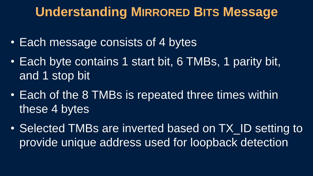
• Each message consists of 4 bytes
• Each byte contains 1 start bit, 6 TMBs, 1 parity bit,
and 1 stop bit
• Each of the 8 TMBs is repeated three times within
these 4 bytes
• Selected TMBs are inverted based on TX_ID setting to
provide unique address used for loopback detection
Understanding MIRRORED BITS Message
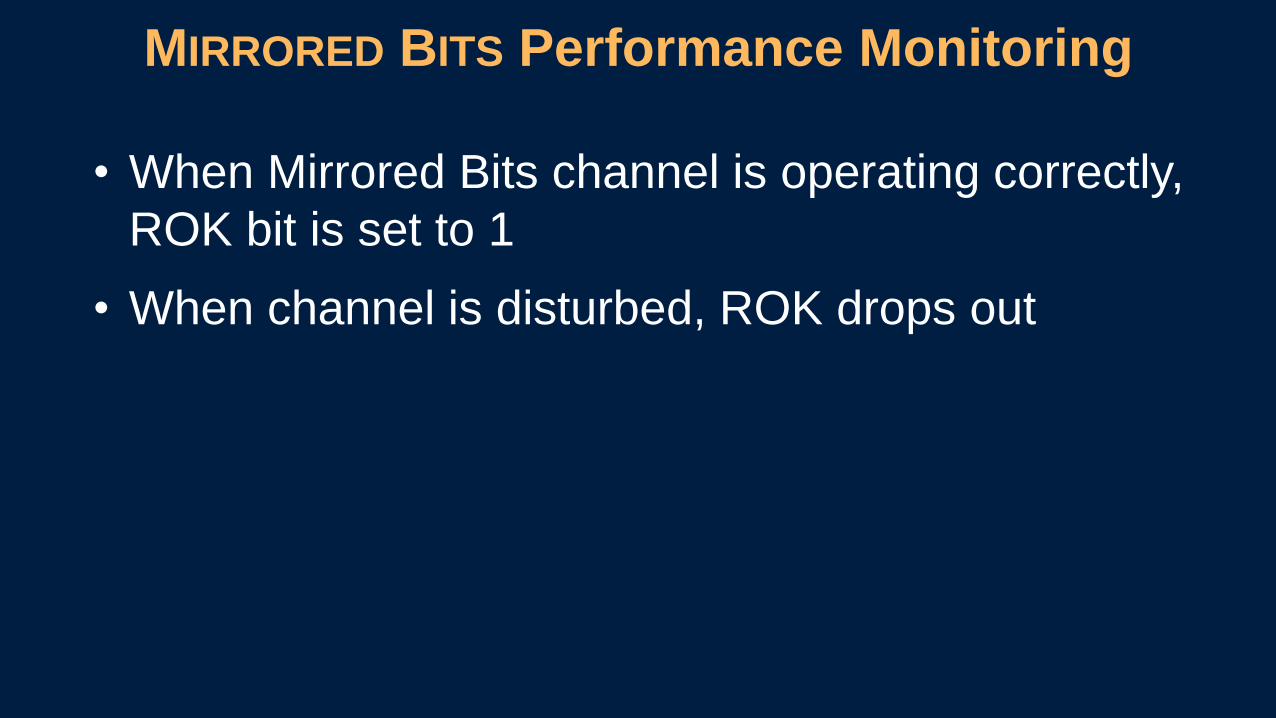
• When Mirrored Bits channel is operating correctly,
ROK bit is set to 1
• When channel is disturbed, ROK drops out
MIRRORED BITS Performance Monitoring
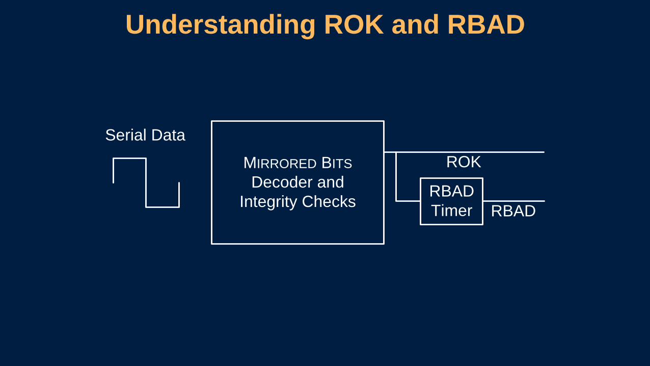
MIRRORED BITS
Decoder and
Integrity Checks
ROK
RBAD
Timer RBAD
Serial Data
Understanding ROK and RBAD
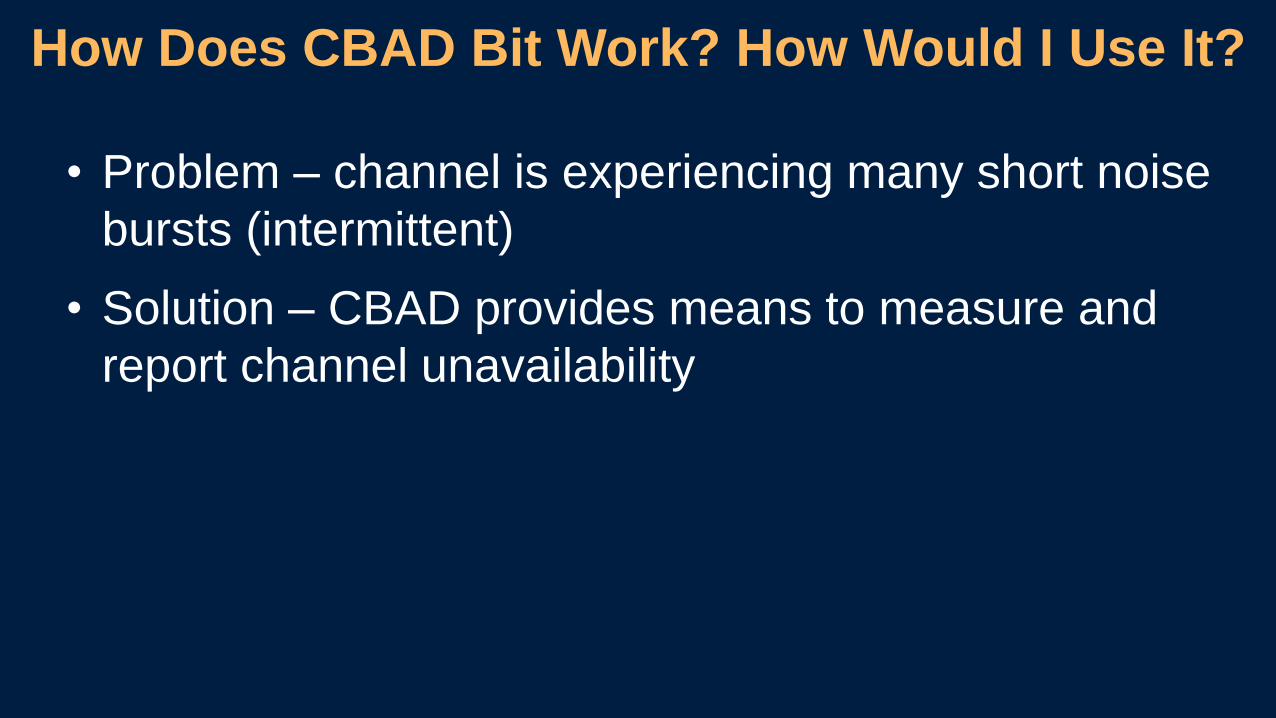
• Problem – channel is experiencing many short noise
bursts (intermittent)
• Solution – CBAD provides means to measure and
report channel unavailability
How Does CBAD Bit Work? How Would I Use It?

MIRRORED BITS Communications
Fiber Optic
Relay 1 Relay 2
Fiber Optic
Relay Without MIRRORED BITS
Relay 1 Relay 2
Relay With MIRRORED BITS
Relay Communications Media
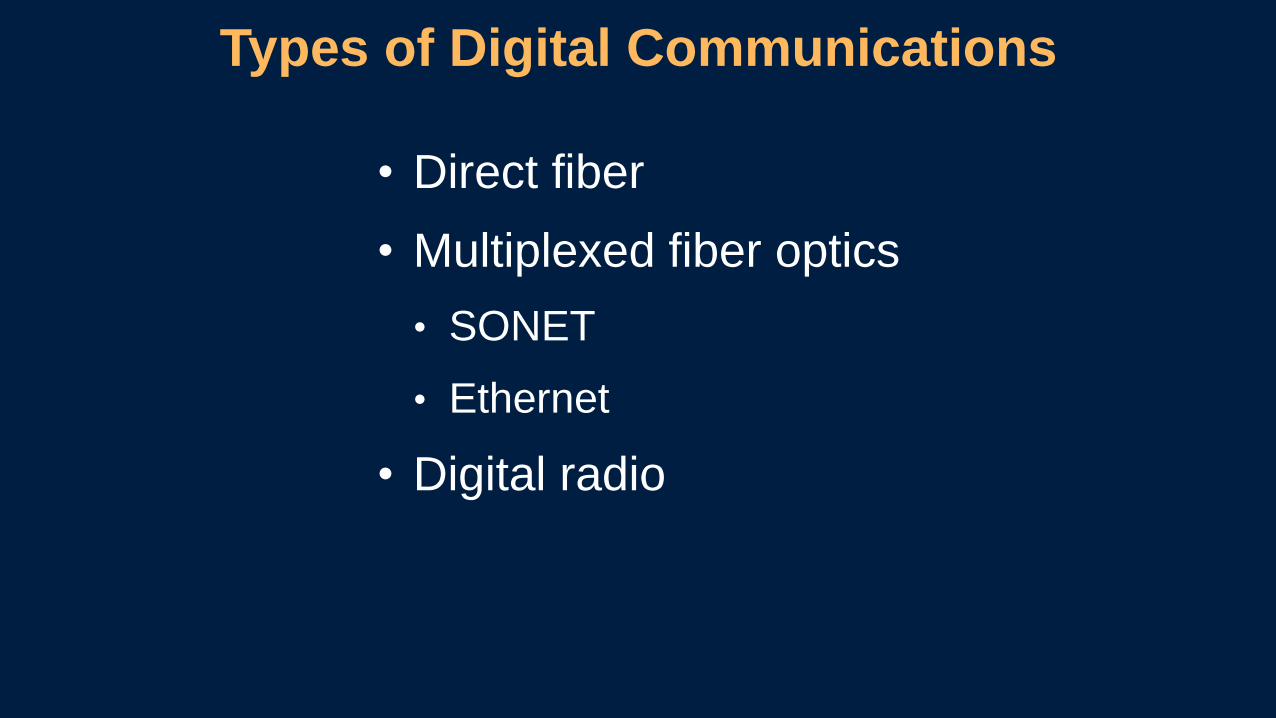
• Direct fiber
• Multiplexed fiber optics
• SONET
• Ethernet
• Digital radio
Types of Digital Communications
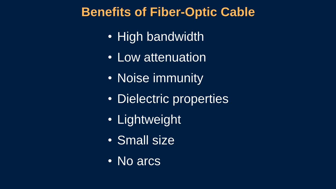
Benefits of Fiber-Optic Cable
• High bandwidth
• Low attenuation
• Noise immunity
• Dielectric properties
• Lightweight
• Small size
• No arcs

• Wavelength is “color” of light in electromagnetic spectrum
• Attenuation of glass is reduced at higher wavelengths
• Standard wavelengths are 850, 1,300, and 1,550 nm
Wavelength
Scattering
Atte
nua
tion
Wavelength850 1,300 1,550
Wavelength (nm)
UV Visible Infrared
850 1,300 1,550
Now select the “pipe” to transmit the signal through
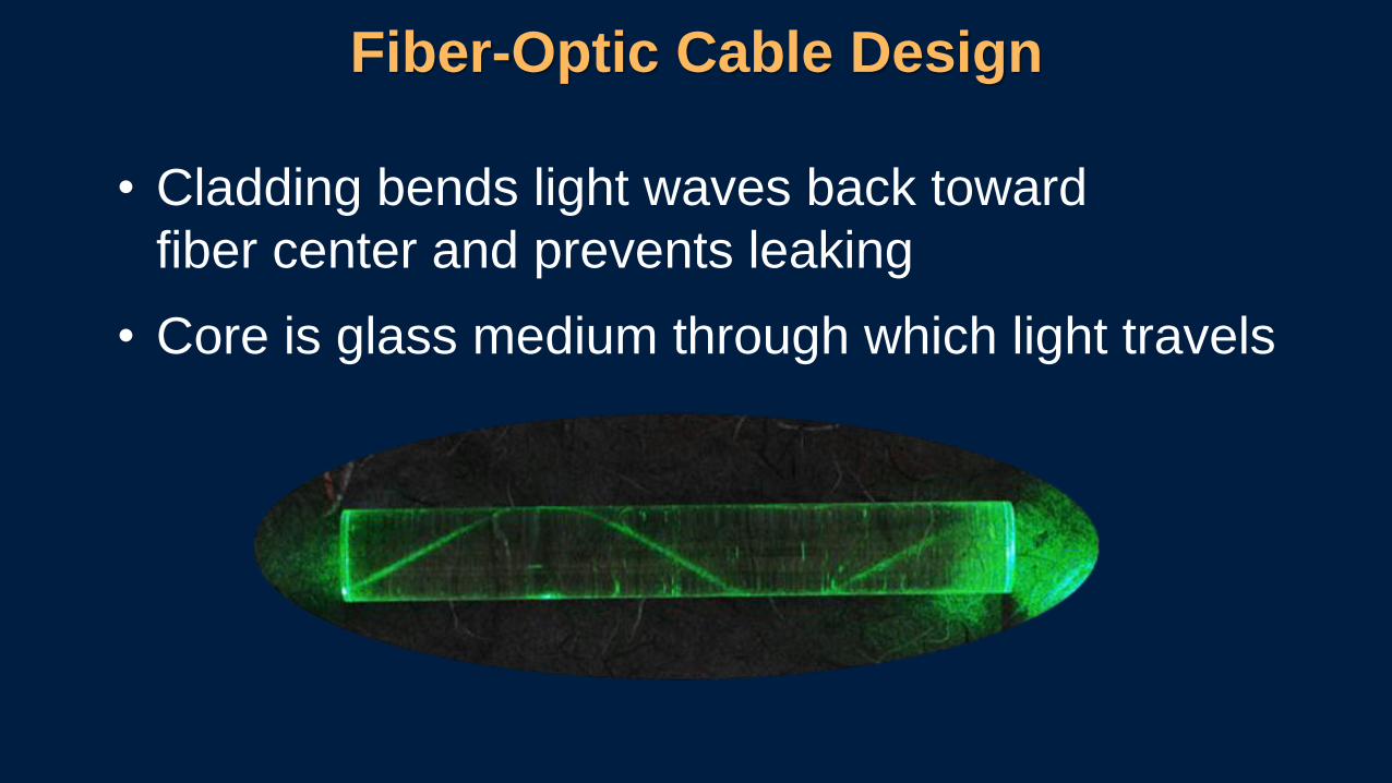
Fiber-Optic Cable Design
• Cladding bends light waves back toward
fiber center and prevents leaking
• Core is glass medium through which light travels

• Operates best at 850 and 1,300 nm
• Has core diameter of 50, 62.5,
or 100 µm (large)
• Uses LED to transmit
• Disperses light waves into numerous
paths as they travel through core
• Is good for short and medium distances
(within building or campus)
• Has blue or orange jacket
Multimode Fiber
Cladding Glass
Core Glass
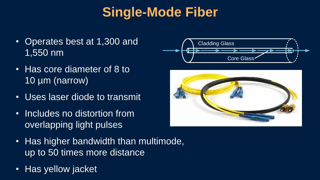
• Operates best at 1,300 and
1,550 nm
• Has core diameter of 8 to
10 µm (narrow)
• Uses laser diode to transmit
• Includes no distortion from
overlapping light pulses
• Has higher bandwidth than multimode,
up to 50 times more distance
• Has yellow jacket
Single-Mode Fiber
Cladding Glass
Core Glass

Fiber-Optic Data Transmission
LED or Laser
Photodiode
Connectors
Transmitter
ReceiverOutput
Input
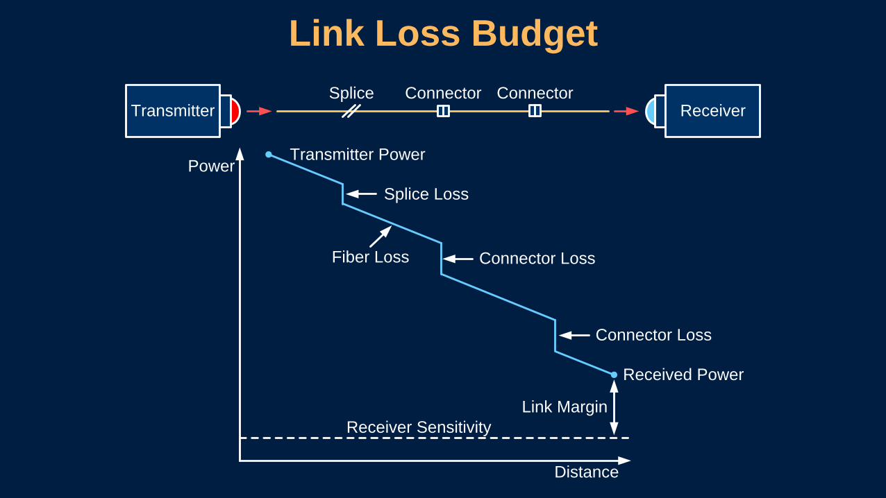
Link Loss Budget
Transmitter ReceiverSplice Connector Connector
Power
Distance
Receiver Sensitivity
Link Margin
Received Power
Connector Loss
Connector LossFiber Loss
Splice Loss
Transmitter Power
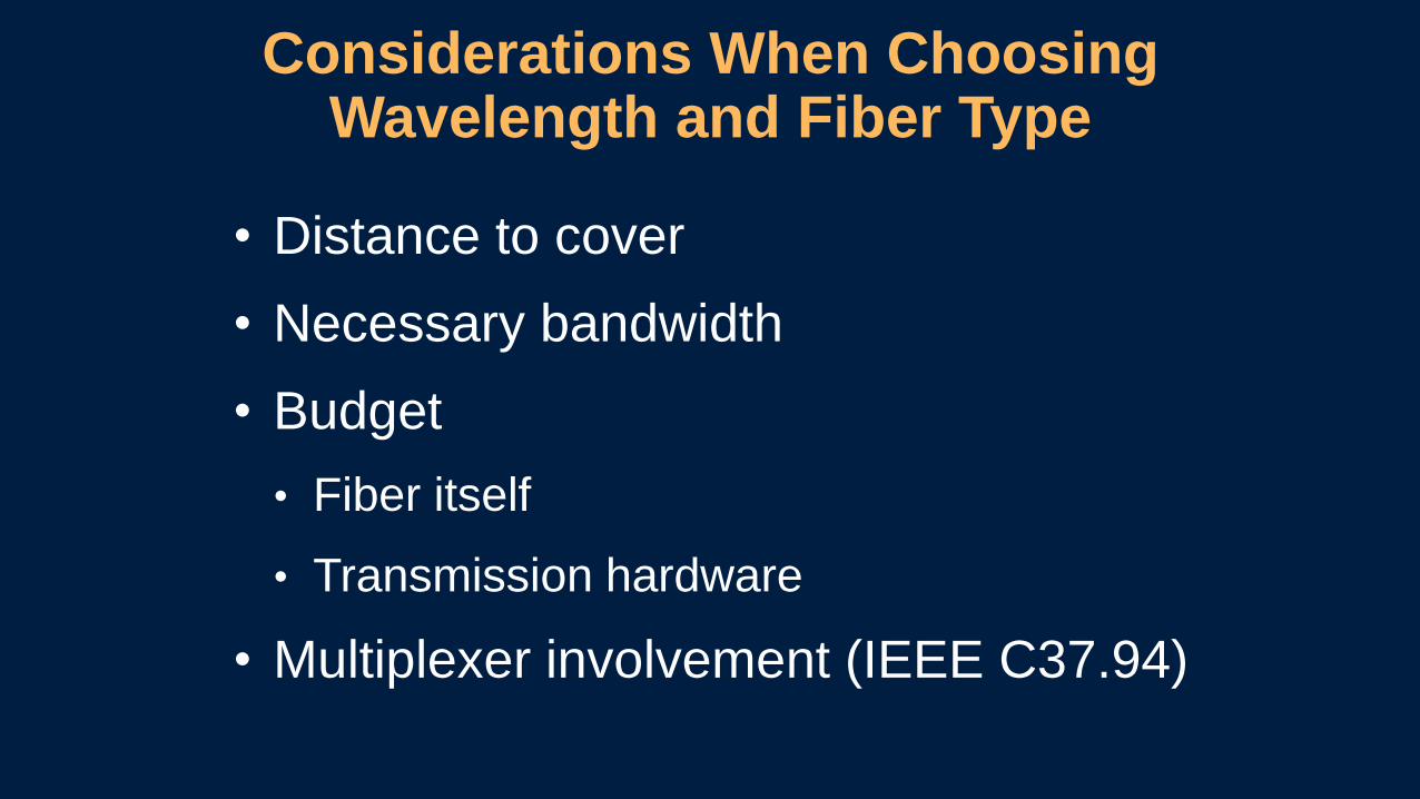
• Distance to cover
• Necessary bandwidth
• Budget
• Fiber itself
• Transmission hardware
• Multiplexer involvement (IEEE C37.94)
Considerations When Choosing Wavelength and Fiber Type
Conclusions• An Inverter cannot be represented as voltage source
behind an impedance like traditional power sources
• Traditional Distribution Protection struggles to detect
fault currents supplied by inverters because inverters
do not generate high fault or sequence currents
• Voltage elements area possible alternative to over
current elements (Vector shift is the fastest anti-
islanding detection method).
• Communications-Assisted Tripping schemes are a
simple and effect way to provide protection for a DG

www.electricities.com
FOLLOW US ON SOCIAL MEDIA:
@ncpublicpower
facebook.com/Electricities
@ElectriCitiesNC