protection profile for virtualization - niap-ccevs
TRANSCRIPT

1
Protection Profile for Virtualization
Version: 1.0 2016-11-17
National Information Assurance Partnership

2
Revision History
Version Date Comment
v1.0 2016-11-17 Initial publication

3
Table of Contents
1 Introduction ................................................................................................................... 5
1.1 Overview ............................................................................................................................5
1.2 Terms .................................................................................................................................5
1.2.1 Common Criteria Terms ........................................................................................................ 5
1.2.2 Technology Terms ................................................................................................................. 5
1.3 Compliant Targets of Evaluation ..........................................................................................8
1.3.1 TOE Boundary ....................................................................................................................... 8
1.3.2 Requirements Met by the Platform ...................................................................................... 9
1.3.3 Scope of Certification ............................................................................................................ 9
1.3.4 Vendor Attestation ............................................................................................................. 10
1.3.5 Product and Platform Equivalence ..................................................................................... 10
1.4 Use Cases .......................................................................................................................... 10
2 Conformance Claims ..................................................................................................... 11
3 Security Problem Description ........................................................................................ 12
3.1 Threats ............................................................................................................................. 12
3.2 Assumptions ..................................................................................................................... 14
3.3 Organizational Security Policies ......................................................................................... 14
4 Security Objectives ....................................................................................................... 15
4.1 Security Objectives for the TOE .......................................................................................... 15
4.2 Security Objectives for the Operational Environment ......................................................... 17
4.3 Security Objectives Rationale ............................................................................................ 18
5 Security Requirements .................................................................................................. 20
5.1 TOE Security Functional Requirements ............................................................................... 20
5.1.1 Security Audit (FAU) ............................................................................................................ 20
5.1.2 Cryptographic Support (FCS) ............................................................................................... 25
5.1.3 User Data Protection (FDP) ................................................................................................. 45
5.1.4 Identification and Authentication (FIA) .............................................................................. 51
5.1.5 Security Management (FMT) .............................................................................................. 55
5.1.6 Protection of the TSF (FPT) ................................................................................................. 56
5.1.7 TOE Access (FTA) ................................................................................................................. 65
5.1.8 Trusted Path/Channel (FTP) ................................................................................................ 65
5.2 TOE Security Assurance Requirements ............................................................................... 67
5.2.1 Class ASE: Security Target Evaluation ................................................................................. 67
5.2.2 Class ADV: Development ..................................................................................................... 67
5.2.3 Class AGD: Guidance Documents ........................................................................................ 69
5.2.4 Class ALC: Life-Cycle Support .............................................................................................. 71
5.2.5 Class ATE: Tests ................................................................................................................... 73
5.2.6 Class AVA: Vulnerability Assessment .................................................................................. 75
Annex A. Optional Requirements ................................................................................... 77

4
Annex B. Selection-Based Requirements ........................................................................ 80
Annex C. Objective Requirements ................................................................................... 115
Annex D. Entropy Documentation and Assessment ...................................................... 119
D.1 Design Description .......................................................................................................... 119
D.2 Entropy Justification ........................................................................................................ 119
D.3 Operating Conditions ...................................................................................................... 119
D.4 Health Testing ................................................................................................................. 119
Annex E. References ....................................................................................................... 120
Annex F. Acronyms ...................................................................................................... 121

5
1 Introduction
1.1 Overview The scope of this Protection Profile (PP) is to describe the security functionality of virtualization technologies in terms of [CC] and to define security functional and assurance requirements for such products. This PP is not complete in itself, but rather provides a set of requirements that are common to the Extended Packages (EP) for Server Virtualization and for Client Virtualization. These capabilities have been broken out into this generic ‘base’ PP due to the high degree of similarity between the two product types.
Due to the increasing prevalence of virtualization technology in enterprise computing environments, it is essential to ensure that this technology is implemented securely in order to mitigate the risk introduced by sharing multiple computers and their data across a single physical system.
1.2 Terms The following sections provide both Common Criteria and technology terms used in this PP.
1.2.1 Common Criteria Terms Common Criteria (CC)
Common Criteria for Information Technology Security Evaluation (International Standard ISO/IEC 15408).
Common Criteria Testing Laboratory
Within the context of the Common Criteria Evaluation and Validation Scheme (CCEVS), an IT security evaluation facility, accredited by the National Voluntary Laboratory Accreditation Program (NVLAP) and approved by the NIAP Validation Body to conduct Common Criteria-based evaluations.
Common Evaluation Methodology (CEM)
Common Evaluation Methodology for Information Technology Security Evaluation.
Extended Package (EP)
An implementation-independent set of security requirements for a specific subset of products described by a PP.
Protection Profile (PP)
An implementation-independent set of security requirements for a category of products.
Security Assurance Requirement (SAR)
A requirement for how the TOE’s proper implementation of the SFRs is verified by an evaluator.
Security Functional Requirement (SFR)
A requirement for security enforcement by the TOE.
Security Target (ST) A set of implementation-dependent security requirements for a specific product.
Target of Evaluation (TOE)
The product under evaluation.
TOE Security Functionality (TSF)
The security functionality of the product under evaluation.
TOE Summary Specification (TSS)
A description of how a TOE satisfies the SFRs in an ST.
1.2.2 Technology Terms Term Meaning
Administrator Administrators perform management activities on the VS. These management functions do not include administration of software running within Guest

6
VMs, such as the Guest OS. Administrators need not be human as in the case of embedded or headless VMs. Administrators are often nothing more than software entities that operate within the VM.
Auditor Auditors are responsible for managing the audit capabilities of the TOE. An Auditor may also be an Administrator. It is not a requirement that the TOE be capable of supporting an Auditor role that is separate from that of an Administrator.
Domain A Domain or Information Domain is a policy construct that groups together execution environments and networks by sensitivity of information and access control policy. For example, classification levels represent information domains. Within classification levels, there might be other domains representing communities of interest or coalitions. In the context of a VS, information domains are generally implemented as collections of VMs connected by virtual networks. The VS itself can be considered an Information Domain, as can its Management Subsystem.
Guest Network See Operational Network.
Guest Operating System (OS)
An operating system that runs within a Guest VM.
Guest VM A Guest VM is a VM that contains a virtual environment for the execution of an independent computing system. Virtual environments execute mission workloads and implement customer-specific client or server functionality in Guest VMs, such as a web server or desktop productivity applications.
Helper VM A Helper VM is a VM that performs services on behalf of one or more Guest VMs, but does not qualify as a Service VM—and therefore is not part of the VMM. Helper VMs implement functions or services that are particular to the workloads of Guest VMs. For example, a VM that provides a virus scanning service for a Guest VM would be considered a Helper VM. For the purposes of this document, Helper VMs are considered a type of Guest VM, and are therefore subject to all the same requirements, unless specifically stated otherwise.
Host Operating System (OS)
An operating system onto which a VS is installed. Relative to the VS, the Host OS is part of the Platform.
Hypervisor 1 The Hypervisor is part of the VMM. It is the software executive of the physical platform of a VS. A Hypervisor’s primary function is to mediate access to all CPU and memory resources, but it is also responsible for either the direct management or the delegation of the management of all other hardware devices on the hardware platform.
Hypercall An API function that allows VM-aware software running within a VM to invoke VMM functionality.
Information Domain See Domain.
Introspection A capability that allows a specially designated and privileged domain to have visibility into another domain for purposes of anomaly detection or monitoring.
Management Network
A network, which may have both physical and virtualized components, used to manage and administer a VS. Management networks include networks used by VS Administrators to communicate with management components of the VS, and networks used by the VS for communications between VS

7
components. For purposes of this document, networks that connect physical hosts for purposes of VM transfer or coordinate, and backend storage networks are considered management networks.
Management Subsystem
Components of the VS that allow VS Administrators to configure and manage the VMM, as well as configure Guest VMs. VMM management functions include VM configuration, virtualized network configuration, and allocation of physical resources.
Operational Network An Operational Network is a network, which may have both physical and virtualized components, used to connect Guest VMs to each other and potentially to other entities outside of the VS. Operational Networks support mission workloads and customer-specific client or server functionality. Also called a “Guest Network.”
Physical Platform The hardware environment on which a VS executes. Physical platform resources include processors, memory, devices, and associated firmware.
Platform The hardware, firmware, and software environment into which a VS is installed and executes.
Service VM 2 A Service VM is a VM whose purpose is to support the Hypervisor in providing the resources or services necessary to support Guest VMs. Service VMs may implement some portion of Hypervisor functionality, but also may contain important system functionality that is not necessary for Hypervisor operation. As with any VM, Service VMs necessarily execute without full Hypervisor privileges—only the privileges required to perform its designed functionality. Examples of Service VMs include device driver VMs that manage access to a physical devices, and name-service VMs that help establish communication paths between VMs.
System Security Policy (SSP)
The overall policy enforced by the VS defining constraints on the behavior of VMs and users.
User Users operate Guest VMs and are subject to configuration policies applied to the VS by Administrators. Users need not be human as in the case of embedded or headless VMs, users are often nothing more than software entities that operate within the VM.
Virtual Machine (VM)
A Virtual Machine is a virtualized hardware environment in which an operating system may execute.
Virtual Machine Manager (VMM)
A VMM is a collection of software components responsible for enabling VMs to function as expected by the software executing within them. Generally, the VMM consists of a Hypervisor, Service VMs, and other components of the VS, such as virtual devices, binary translation systems, and physical device drivers. It manages concurrent execution of all VMs and virtualizes platform resources as needed.
Virtualization System (VS)
3 A software product that enables multiple independent computing systems to execute on the same physical hardware platform without interference from one other. For the purposes of this document, the VS consists of a Virtual Machine Manager (VMM), Virtual Machine (VM) abstractions, a management subsystem, and other components.

8
1.3 Compliant Targets of Evaluation
A Virtualization System (VS) is a software product that enables multiple independent computing systems to execute on the same physical hardware platform without interference from one other. A VS creates a virtualized hardware environment (virtual machines or VMs) for each instance of an operating system permitting these environments to execute concurrently while maintaining isolation and the appearance of exclusive control over assigned computing resources. For the purposes of this document, the VS consists of a Virtual Machine Manager (VMM), Virtual Machine (VM) abstractions, a management subsystem, and other components.
A VMM is a collection of software components responsible for enabling VMs to function as expected by the software executing within them. Generally, the VMM consists of a Hypervisor, Service VMs, and other components of the VS, such as virtual devices, binary translation systems, and physical device drivers. It manages concurrent execution of all VMs and virtualizes platform resources as needed.
The Hypervisor is the software executive of the physical platform of a Virtualization System. A hypervisor operates at the highest CPU privilege level and manages access to all of the physical resources of the hardware platform. It exports a well-defined, protected interface for access to the resources it manages. A Hypervisor’s primary function is to mediate access to all CPU and memory resources, but it is also responsible for either the direct management or the delegation of the management of all other hardware devices on the hardware platform. This document does not specify any Hypervisor-specific requirements, though many VMM requirements would naturally apply to a Hypervisor.
A Service VM is a VM whose purpose is to support the Hypervisor in providing the resources or services necessary to support Guest VMs. Service VMs may implement some portion of Hypervisor functionality, but also may contain important system functionality that is not necessary for Hypervisor operation. As with any VM, Service VMs necessarily execute without full Hypervisor privileges—only the privileges required to perform its designed functionality. Examples of Service VMs include device driver VMs that manage access to physical devices, and name-service VMs that help establish communication paths between VMs.
A Guest VM is a VM that contains a virtual environment for the execution of an independent computing system. Virtual environments execute mission workloads and implement customer-specific client or server functionality in Guest VMs, such as a web server or desktop productivity applications. A Helper VM is a VM that performs services on behalf of one or more Guest VMs, but does not qualify as a Service VM—and therefore is not part of the VMM. Helper VMs implement functions or services that are particular to the workloads of Guest VMs. For example, a VM that provides a virus scanning service for a Guest VM would be considered a Helper VM. The line between Helper and Service VMs can easily be blurred. For instance, a VM that implements a cryptographic function—such as an in-line encryption VM—could be identified as either a Service or Helper VM depending on the particular virtualization solution. If the cryptographic functions are necessary only for the privacy of Guest VM data in support of the Guest’s mission applications, it would be proper to classify the encryption VM as a Helper. But if the encryption VM is necessary for the VMM to isolate Guest VMs, it would be proper to classify the encryption VM as a Service VM. For the purposes of this document, Helper VMs are subject to all requirements that apply to Guest VMs, unless specifically stated otherwise.
1.3.1 TOE Boundary Figure 1 shows a greatly simplified view of a generic Virtualization System and Platform. TOE
components are displayed in Red. Non-TOE components are in Blue. The Platform is the hardware,

9
firmware, and software onto which the VS is installed. The VMM includes the Hypervisor, Service VMs,
and VM containers, but not the software that runs inside Guest VMs or Helper VMs. The Management
Subsystem is part of the TOE, but may or may not be part of the VMM.
Figure 1. Virtualization System and Platform
For purposes of this Protection Profile, the Virtualization System is the TOE, subject to some caveats. The Platform onto which the VS is installed (which includes hardware, platform firmware, and Host Operating System) is not part of the TOE. Software installed with the VS on the Host OS specifically to support the VS or implement VS functionality is part of the TOE. General purpose software—such as device drivers for physical devices and the Host OS itself—is not part of the TOE, regardless of whether it supports VS functionality or runs inside a Service VM or control domain. Software that runs within Guest and Helper VMs is not part of the TOE.
In general, for virtualization products that are installed onto “bare metal,” the entire set of installed components constitute the TOE, and the hardware constitute the Platform. Also in general, for products that are hosted by or integrated into a commodity operating system, the components installed expressly for implementing and supporting virtualization are in the TOE, and the Platform comprises the hardware and Host OS.
1.3.2 Requirements Met by the Platform
Depending on the way the VS is installed, functions tested under this PP may be implemented by the TOE or by the Platform. There is no difference in the testing required whether the function is implemented by the TOE or by the Platform. In either case, the tests determine whether the function being tested provides a level of assurance acceptable to meet the goals of this Profile with respect to a particular product and platform. The equivalency guidelines are intended in part to address this TOE vs. Platform distinction, and to ensure that the assurance level does not change between instances of equivalent products on equivalent platforms—and also, of course, to ensure that the appropriate testing is done when the distinction is significant.
1.3.3 Scope of Certification
Successful evaluation of a Virtualization System against this profile does not constitute or imply successful evaluation of any Host Operating System or Platform—no matter how tightly integrated with the VS. The Platform, including any Host OS, supports the VS through provision of services and resources. Specialized VS components installed on or in a Host OS to support the VS may be considered part of the TOE. But
Platform
Hypervisor
Helper VM
Guest VM
Service VM
Mgmt Subsys
VMM
Virtualization
System

10
general-purpose OS components and functions—whether or not they support the VS—are not part of the TOE, and thus are not evaluated under this PP.
1.3.4 Vendor Attestation
This PP includes several SFRs that include elements that are met via vendor attestation. Attestation assurance activities are reserved for SFRs that define properties that are critical to the system’s security functionality, but that are impossible or impractical to test in a repeatable and consistent manner. These Attestation assurance activities require the vendor to make an assertion in the ST that their product meets the specified SFR—no further testing or assessment of the product regarding these SFRs or elements is performed by the CCTL. The CCTL will simply verify that the ST includes a pre-determined Attestation statement. By including this statement in the ST, the vendor is accepting responsibility for the assurance of their product in these particular areas. If at any time evidence is produced that indicates that these statements are false (and the product does not meet the specified security functionality), the CC certificate may be revoked. See FDP_VMS_EXT.1, FDP_VNC_EXT.1, FPT_VDP_EXT.1, and FPT_VIV_EXT.1 for the associated Attestation statements.
1.3.5 Product and Platform Equivalence
The tests in this Protection Profile must be run on all product versions and Platforms with which the Vendor would like to claim compliance—subject to this Profile’s equivalency guidelines (to be published).
1.4 Use Cases
This base PP does not define any use cases for virtualization technology. Client Virtualization and Server
Virtualization products have different use cases and so these are defined in their respective EPs.

11
2 Conformance Claims
Conformance Statement
To be conformant to this PP, an ST must demonstrate Exact Conformance, a subset of Strict Conformance as defined in [CC] Part 1 (ASE_CCL). The ST must include all components in this PP that are:
Unconditional (which are always required)
Selection-based (which are required when certain selections are chosen in the unconditional requirements)
It may also include components that are:
Optional
Objective
Unconditional requirements are found in the main body of the document (Section 5), while appendices contain the selection-based, optional, and objective requirements. The ST may iterate any of these components but it must not introduce any additional component (e.g., from CC Part 2 or 3) that is not defined in this PP.
CC Conformance Claims
This PP is conformant to Parts 2 (extended) and 3 (extended) of Common Criteria Version 3.1, Revision 4 [CC].
PP Claims
This PP does not claim conformance to any Protection Profile.
Package Claims
This PP does not claim conformance to any packages.

12
3 Security Problem Description
Regardless of whether a virtualization product is embodied as client virtualization or server virtualization, there are a number of common threats that must be mitigated in order to have assurance that it is operating securely.
3.1 Threats T.DATA_LEAKAGE
It is a fundamental property of VMs that the domains encapsulated by different VMs remain separate unless data sharing is permitted by policy. For this reason, all Virtualization Systems shall support a policy that prohibits information transfer between VMs.
It shall be possible to configure VMs such that data cannot be moved between domains from VM to VM, or through virtual or physical network components under the control of the VS. When VMs are configured as such, it shall not be possible for data to leak between domains, neither by the express efforts of software or users of a VM, nor because of vulnerabilities or errors in the implementation of the VMM or other VS components.
If it is possible for data to leak between domains when prohibited by policy, then an adversary on one domain or network can obtain data from another domain. Such cross-domain data leakage can, for example, cause classified information, corporate proprietary information, or personally identifiable information to be made accessible to unauthorized entities.
T.UNAUTHORIZED_UPDATE
It is common for attackers to target outdated versions of software containing known flaws. This means it is extremely important to update Virtualization System software as soon as possible when updates are available. But the source of the updates and the updates themselves must be trusted. If an attacker can write their own update containing malicious code they can take control of the VS.
T.UNAUTHORIZED_MODIFICATION
System integrity is a core security objective for Virtualization Systems. To achieve system integrity, the integrity of each VMM component must be established and maintained. Malware running on the platform must not be able to undetectably modify Virtualization System components while the system is running or at rest. Likewise, malicious code running within a virtual machine must not be able to modify Virtualization System components.
T.USER_ERROR
If a Virtualization System is capable of simultaneously displaying VMs of different domains to the same user at the same time, there is always the chance that the user will become confused and unintentionally leak information between domains. This is especially likely if VMs belonging to different domains are indistinguishable. Malicious code may also attempt to interfere with the user’s ability to distinguish between domains. The VS must take measures to minimize the likelihood of such confusion.
T.3P_SOFTWARE
In some VS implementations, critical functions are by necessity performed by software not produced by the virtualization vendor. Such software may include Host Operating Systems and physical device drivers. Vulnerabilities in this software can be exploited by an adversary and result in VMM

13
compromise. Where possible, the VS should mitigate the results of potential vulnerabilities or malicious content in third-party code.
T.VMM_COMPROMISE
The Virtualization System is designed to provide the appearance of exclusivity to the VMs and is designed to separate or isolate their functions except where specifically shared. Failure of security mechanisms could lead to unauthorized intrusion into or modification of the VMM, or bypass of the VMM altogether. This must be prevented to avoid compromising the Virtualization System.
T.PLATFORM_COMPROMISE
The VS must be capable of protecting the platform from threats that originate within VMs and operational networks connected to the VS. The hosting of untrusted—even malicious—domains by the VS cannot be permitted to compromise the security and integrity of the platform on which the VS executes. If an attacker can access the underlying platform in a manner not controlled by the VMM, the attacker might be able to modify system firmware or software—compromising both the Virtualization System and the underlying platform.
T.UNAUTHORIZED_ACCESS
Functions performed by the management layer include VM configuration, virtualized network configuration, allocation of physical resources, and reporting. Only certain authorized system users (administrators) are allowed to exercise management functions.
Virtualization Systems are often managed remotely over communication networks. Members of these networks can be both geographically and logically separated from each other, and pass through a variety of other systems which may be under the control of an adversary, and offer the opportunity for communications to be compromised. An adversary with access to an open management network could inject commands into the management infrastructure. This would provide an adversary with administrator privilege on the platform, and administrative control over the VMs and virtual network connections. The adversary could also gain access to the management network by hijacking the management network channel.
T.WEAK_CRYPTO
To the extent that VMs appear isolated within the Virtualization System, a threat of weak cryptography may arise if the VMM does not provide good entropy to support security-related features that depend on entropy to implement cryptographic algorithms. For example, a random number generator keeps an estimate of the number of bits of noise in the entropy pool. From this entropy pool random numbers are created. Good random numbers are essential to implementing strong cryptography. Cryptography implemented using poor random numbers can be defeated by a sophisticated adversary.
T.UNPATCHED_SOFTWARE
Vulnerabilities in outdated or unpatched software can be exploited by adversaries to compromise the Virtualization System or platform.
T.MISCONFIGURATION
The Virtualization System may be misconfigured, which could impact its functioning and security. This misconfiguration could be due to an administrative error or the use of faulty configuration data.
T.DENIAL_OF_SERVICE

14
A VM may block others from system resources (e.g., system memory, persistent storage, and processing time) via a resource exhaustion attack.
3.2 Assumptions A.PLATFORM_INTEGRITY
The platform has not been compromised prior to installation of the Virtualization System.
A.PHYSICAL Physical security commensurate with the value of the TOE and the data it contains is assumed to be
provided by the environment.
A.TRUSTED_ADMIN TOE Administrators are trusted to follow and apply all administrator guidance.
A.COVERT_CHANNELS
If the TOE has covert storage or timing channels, then for all VMs executing on that TOE, it is
assumed that relative to the IT assets to which they have access, those VMs will have assurance
sufficient to outweigh the risk that they will violate the security policy of the TOE by using those
covert channels.
A.NON_MALICIOUS_USER
The user of the VS is not willfully negligent or hostile, and uses the VS in compliance with the applied
enterprise security policy and guidance. At the same time, malicious applications could act as the
user, so requirements which confine malicious applications are still in scope.
3.3 Organizational Security Policies There are no organizational security policies defined for this PP.

15
4 Security Objectives
4.1 Security Objectives for the TOE O.VM_ISOLATION
VMs are the fundamental subject of the system. The VMM is responsible for applying the system security policy (SSP) to the VM and all resources. As basic functionality, the VMM must support a security policy that mandates no information transfer between VMs.
The VMM must support the necessary mechanisms to isolate the resources of all VMs. The VMM partitions a platform's physical resources for use by the supported virtual environments. Depending on the use case, a VM may require a completely isolated environment with exclusive access to system resources, or share some of its resources with other VMs. It must be possible to enforce a security policy that prohibits the transfer of data between VMs through shared devices. When the platform security policy allows the sharing of resources across VM boundaries, the VMM must ensure that all access to those resources is consistent with the policy. The VMM may delegate the responsibility for the mediation of sharing of particular resources to select Service VMs; however in doing so, it remains responsible for mediating access to the Service VMs, and each Service VM must mediate all access to any shared resource that has been delegated to it in accordance with the SSP.
Devices, whether virtual or physical, are resources requiring access control. The VMM must enforce access control in accordance to system security policy. Physical devices are platform devices with access mediated via the VMM per the O.VMM_Integrity objective. Virtual devices may include virtual storage devices and virtual network devices. Some of the access control restrictions must be enforced internal to Service VMs, as may be the case for isolating virtual networks. VMMs may also expose purely virtual interfaces. These are VMM specific, and while they are not analogous to a physical device, they are also subject to access control.
The VMM must support the mechanisms to isolate all resources associated with virtual networks and to limit a VM's access to only those virtual networks for which it has been configured. The VMM must also support the mechanisms to control the configurations of virtual networks according to the SSP.
O.VMM_INTEGRITY
Integrity is a core security objective for Virtualization Systems. To achieve system integrity, the integrity of each VMM component must be established and maintained. This objective concerns only the integrity of the Virtualization System—not the integrity of software running inside of Guest VMs or of the physical platform. The overall objective is to ensure the integrity of critical components of a Virtualization System.
Initial integrity of a VS can be established through mechanisms such as a digitally signed installation or update package, or through integrity measurements made at launch. Integrity is maintained in a running system by careful protection of the VMM from untrusted users and software. For example, it must not be possible for software running within a Guest VM to exploit a vulnerability in a device or hypercall interface and gain control of the VMM. The vendor must release patches for vulnerabilities as soon as practicable after discovery.
O.PLATFORM_INTEGRITY
The integrity of the VMM depends on the integrity of the hardware and software on which the
VMM relies. Although the VS does not have complete control over the integrity of the platform, the

16
VS should as much as possible try to ensure that no users or software hosted by the VS is capable of
undermining the integrity of the platform.
O.DOMAIN_INTEGRITY
While the VS is not responsible for the contents or correct functioning of software that runs within Guest VMs, it is responsible for ensuring that the correct functioning of the software within a Guest VM is not interfered with by other VMs.
O.MANAGEMENT_ACCESS
VMM management functions include VM configuration, virtualized network configuration, allocation of physical resources, and reporting. Only certain authorized system users (administrators) are allowed to exercise management functions.
Because of the privileges exercised by the VMM management functions, it must not be possible for the VMM’s management components to be compromised without administrator notification. This means that unauthorized users cannot be permitted access to the management functions, and the management components must not be interfered with by Guest VMs or unprivileged users on other networks—including operational networks connected to the TOE.
VMMs include a set of management functions that collectively allow administrators to configure and manage the VMM, as well as configure Guest VMs. These management functions are specific to the virtualization system, distinct from any other management functions that might exist for the internal management of any given Guest VM. These VMM management functions are privileged, with the security of the entire system relying on their proper use. The VMM management functions can be classified into different categories and the policy for their use and the impact to security may vary accordingly.
The management functions might be distributed throughout the VMM (within the VMM and Service VMs). The VMM must support the necessary mechanisms to enable the control of all management functions according to the system security policy. When a management function is distributed among multiple Service VMs, the VMs must be protected using the security mechanisms of the Hypervisor and any Service VMs involved to ensure that the intent of the system security policy is not compromised. Additionally, since hypercalls permit Guest VMs to invoke the Hypervisor, and often allow the passing of data to the Hypervisor, it is important that the hypercall interface is well-guarded and that all parameters be validated.
The VMM maintains configuration data for every VM on the system. This configuration data, whether of Service or Guest VMs, must be protected. The mechanisms used to establish, modify and verify configuration data are part of the VS management functions and must be protected as such. The proper internal configuration of Service VMs that provide critical security functions can also greatly impact VS security. These configurations must also be protected. Internal configuration of Guest VMs should not impact overall VS security. The overall goal is to ensure that the VMM, including the environments internal to Service VMs, is properly configured and that all Guest VM configurations are maintained consistent with the system security policy throughout their lifecycle.
Virtualization Systems are often managed remotely. For example, an administrator can remotely update virtualization software, start and shut down VMs, and manage virtualized network connections. If a console is required, it could be run on a separate machine or it could itself run in a VM. When performing remote management, an administrator must communicate with a privileged management agent over a network. Communications with the management infrastructure must be protected from Guest VMs and operational networks.

17
O.PATCHED_SOFTWARE
The Virtualization System must be updated and patched when needed in order to prevent the potential compromise of the VMM, as well as the networks and VMs that it hosts. Identifying and applying needed updates must be a normal part of the operating procedure to ensure that patches are applied in a timely and thorough manner. In order to facilitate this, the VS must support standards and protocols that help enhance the manageability of the VS as an IT product, enabling it to be integrated as part of a manageable network (e.g., reporting current patch level and patchability).
O.VM_ENTROPY
VMs must have access to good entropy sources to support security-related features that implement
cryptographic algorithms. For example, in order to function as members of operational networks,
VMs must be able to communicate securely with other network entities—whether virtual or
physical. They must therefore have access to sources of good entropy to support that secure
communication.
O.AUDIT
The purpose of audit is to capture and protect data about what happens on a system so that it can
later be examined to determine what has happened in the past.
O.CORRECTLY_APPLIED_CONFIGURATION
The TOE must not apply configurations that violate the current security policy.
The TOE must correctly apply configurations and policies to newly created Guest VMs, as well as to
existing Guest VMs when applicable configuration or policy changes are made. All changes to
configuration and to policy must conform to the existing security policy. Similarly, changes made to
the configuration of the TOE itself must not violate the existing security policy.
O.RESOURCE_ALLOCATION
The TOE will provide mechanisms that enforce constraints on the allocation of system resources in
accordance with existing security policy.
4.2 Security Objectives for the Operational Environment OE.CONFIG
TOE administrators will configure the Virtualization System correctly to create the intended
security policy.
OE.PHYSICAL Physical security, commensurate with the value of the TOE and the data it contains, is provided
by the environment.
OE.TRUSTED_ADMIN TOE Administrators are trusted to follow and apply all administrator guidance in a trusted
manner.
OE.COVERT_CHANNELS
If the TOE has covert storage or timing channels, then for all VMs executing on that TOE, it is
assumed that those VMs will have sufficient assurance relative to the IT assets to which they

18
have access, to outweigh the risk that they will violate the security policy of the TOE by using
those covert channels.
OE.NON_MALICIOUS_USER
Users are trusted to be not willfully negligent or hostile and use the VS in compliance with the
applied enterprise security policy and guidance.
4.3 Security Objectives Rationale This section describes how the assumptions, threats, and organizational security policies map to the
security objectives. Note that this section only provides mappings for the security objectives defined in
this base PP.
Threat, Assumption, or OSP Security Objective Rationale
T.DATA_LEAKAGE O.VM_ISOLATION O.DOMAIN_INTEGRITY
Logical separation of VMs and enforcement of domain integrity prevent unauthorized transmission of data from one VM to another.
T.UNAUTHORIZED_UPDATE O.VMM_INTEGRITY
System integrity prevents the TOE from installing a software patch containing unknown and potentially malicious code.
T.UNAUTHORIZED_MODIFICATION O.VMM_INTEGRITY O.AUDIT
Enforcement of VMM integrity prevents the bypass of enforcement mechanisms and auditing ensures that abuse of legitimate authority can be detected.
T.USER_ERROR O.VM_ISOLATION
Isolation of VMs includes clear attribution of those VMs to their respective domains which reduces the likelihood that a user inadvertently inputs or transfers data meant for one VM into another.
T.3P_SOFTWARE O.VMM_INTEGRITY
The VMM integrity mechanisms include environment-based vulnerability mitigation and potentially support for introspection and device driver isolation, all of which reduce the likelihood that any vulnerabilities in third-party software can be used to exploit the TOE.
T.VMM_COMPROMISE O.VMM_INTEGRITY O.VM_ISOLATION
Maintaining the integrity of the VMM and ensuring that VMs execute in isolated domains mitigate the risk that the VMM can be compromised or bypassed.

19
T.PLATFORM_COMPROMISE O.PLATFORM_INTEGRITY
Platform integrity mechanisms used by the TOE reduce the risk that an attacker can ‘break out’ of a VM and affect the platform on which the VS is running.
T.UNAUTHORIZED_ACCESS O.MANAGEMENT_ACCESS
Ensuring that TSF management functions cannot be executed without authorization prevents untrusted subjects from modifying the behavior of the TOE in an unanticipated manner.
T.WEAK_CRYPTO O.VM_ENTROPY
Acquisition of good entropy is necessary to support the TOE’s security-related cryptographic algorithms.
T.UNPATCHED_SOFTWARE O.PATCHED_SOFTWARE
The ability to patch the TOE software ensures that protections against vulnerabilities can be applied as they become available.
T.MISCONFIGURATION O.CORRECTLY_APPLIED_CONFIGURATION
Mechanisms to prevent the application of configurations that violate the current security policy help prevent misconfigurations.
T.DENIAL_OF_SERVICE O.RESOURCE_ALLOCATION
The ability of the TSF to ensure the proper allocation of resources makes denial of service attacks more difficult.
A.COVERT_CHANNELS OE.COVERT_CHANNELS
It is expected that any data contained within VMs is commensurate with the security provided by the TOE, which includes any vulnerabilities due to the potential presence of covert storage and/or timing channels.
A.NON_MALICIOUS_USER OE.NON_MALICIOUS_USER If the organization properly vets and trains users, it is expected that they will be non-malicious.
A.PLATFORM_INTEGRITY OE.PLATFORM_INTEGRITY
If the underlying platform has not been compromised prior to installation of the TOE, its integrity can be assumed to be intact.
A.PHYSICAL OE.PHYSICAL
If the TOE is deployed in a location that has appropriate physical safeguards, it can be assumed to be physically secure.
A.TRUSTED_ADMIN OE.TRUSTED_ADMIN Providing guidance to administrators and ensuring that

20
individuals are properly trained and vetted before being given administrative responsibilities will ensure that they are trusted.
5 Security Requirements
5.1 TOE Security Functional Requirements The Security Functional Requirements (SFRs) included in this section are derived from Part 2 of the
Common Criteria for Information Technology Security Evaluation, Version 3.1, Revision 4, with additional
extended functional components.
The CC defines operations on Security Functional Requirements: assignments, selections, assignments within selections and refinements. This document uses the following font conventions to identify the operations defined by the CC:
Assignment: Indicated with italicized text;
Refinement made by EP author: Indicated with bold text;
Selection: Indicated with underlined text;
Assignment within a Selection: Indicated with italicized and underlined text;
Iteration: Indicated by appending the SFR name with a slash and unique identifier suggesting the purpose of the iteration, e.g., ‘/CDR’ for an SFR relating to call detail records;
Extended SFRs: identified by having a label “EXT” after the SFR name.
5.1.1 Security Audit (FAU)
FAU_GEN.1 Audit Data Generation FAU_GEN.1.1 The TSF shall be able to generate an audit record of the following auditable
events:
a. Start-up and shutdown of audit functions;
b. All administrative actions;
c. [Specifically defined auditable events in Table 1]
d. [selection: additional information defined in Table 2, additional
information defined in Table 3, additional information defined in Table 4,
additional information defined in in Table 5, no other information].
FAU_GEN.1.2 The TSF shall record within each audit record at least the following information:
a. Date and time of the event;
b. Type of event;
c. Subject and object identity (if applicable);
d. The outcome (success or failure) of the event;
e. [Additional information defined in Table 1]; and

21
f. [selection: additional information defined in Table 2, additional
information defined in Table 3, additional information defined in Table 4,
additional information defined in in Table 5, no other information].
Application Note: The ST author can include other auditable events directly in Table 1; they are not
limited to the list presented. The ST author should update the table in
FAU_GEN.1.2 with any additional information generated. “Subject identity” in
FAU_GEN.1.2 could be a user id or an identifier specifying a VM, for example.
The Table 1 entry for FDP_VNC_EXT.1 refers to configuration settings that attach VMs to virtualized network components. Changes to these configurations can be made during VM execution or when VMs are not running. Audit records must be generated for either case.
The intent of the audit requirement for FDP_PPR_EXT.1 is to log that the VM is connected to a physical device (when the device becomes part of the VM’s hardware view), not to log every time that the device is accessed. Generally, this is only once at VM startup. However, some devices can be connected and disconnected during operation (e.g., virtual USB devices such as CD-ROMs). All such connection/disconnection events must be logged.
Assurance Activity
The evaluator shall check the TSS and ensure that it lists all of the auditable events and provides a format for audit records. Each audit record format type shall be covered, along with a brief description of each field. The evaluator shall check to make sure that every audit event type mandated by the PP is described in the TSS.
The evaluator shall also make a determination of the administrative actions that are relevant in the context of this PP. The evaluator shall examine the administrative guide and make a determination of which administrative commands, including subcommands, scripts, and configuration files, are related to the configuration (including enabling or disabling) of the mechanisms implemented in the TOE that are necessary to enforce the requirements specified in the PP. The evaluator shall document the methodology or approach taken while determining which actions in the administrative guide are security-relevant with respect to this PP.
The evaluator shall test the TOE’s ability to correctly generate audit records by having the TOE generate audit records for the events listed and administrative actions. For administrative actions, the evaluator shall test that each action determined by the evaluator above to be security relevant in the context of this PP is auditable. When verifying the test results, the evaluator shall ensure the audit records generated during testing match the format specified in the administrative guide, and that the fields in each audit record have the proper entries.
Note that the testing here can be accomplished in conjunction with the testing of the security mechanisms directly.

22
Table 1: Auditable Events
Requirement Auditable Events Additional Audit Record Contents
FAU_GEN.1 1 None. 2 None.
FAU_SAR.1 3 None. 4 None.
FAU_STG.1 5 None. 6 None.
FAU_STG_EXT.1 7 Failure of audit data capture due to lack of disk space or pre-defined limit.
8 On failure of logging function, capture record of failure and record upon restart of logging function.
9 None
FCS_CKM.1 10 None. 11 None.
FCS_CKM.2 12 None. 13 None.
FCS_CKM_EXT.4 14 None. 15 None.
FCS_COP.1(1) 16 None. 17 None.
FCS_COP.1(2) 18 None. 19 None.
FCS_COP.1(3) 20 None. 21 None.
FCS_COP.1(4) 22 None. 23 None.
FCS_ENT_EXT.1 24 None. 25 None.
FCS_RBG_EXT.1 26 Failure of the randomization process. 27 No additional information.
FDP_HBI_EXT.1 28 None. 29 None.
FDP_PPR_EXT.1 30 Successful and failed VM connections to physical devices where connection is governed by configurable policy.
31 Security policy violations.
32 VM and physical device identifiers. 33 Identifier for the security policy that
was violated.
FDP_RIP_EXT.1 34 None. 35 None.
FDP_RIP_EXT.2 36 None. 37 None.
FDP_VMS_EXT.1 38 None. 39 None.
FDP_VNC_EXT.1 40 Successful and failed attempts to connect VMs to virtual and physical networking components.
41 Security policy violations. 42 Administrator configuration of inter-VM
communications channels between VMs.
43 VM and virtual or physical networking component identifiers.
44 Identifier for the security policy that was violated.
FIA_UAU.5 45 None. 46 None.
FIA_UIA_EXT.1 47 Administrator authentication attempts 48 All use of the identification and
authentication mechanism.
49 Provided user identity, origin of the attempt (e.g., console, remote IP address).
FMT_MSA_EXT.1 50 None. 51 None.
FMT_SMO_EXT.1 52 None. 53 None.
FMT_SMR.2 54 None. 55 None.
FPT_DVD_EXT.1 56 None. 57 None.
FPT_EEM_EXT.1 58 None. 59 None.
FPT_HAS_EXT.1 60 None. 61 None.

23
FPT_HCL_EXT.1 62 Attempts to access disabled hypercall interfaces.
63 Security policy violations.
64 Interface for which access was attempted.
65 Identifier for the security policy that was violated.
FPT_RDM_EXT.1 66 Transfer of removable media or device between VMs.
67 None.
FPT_TUD_EXT.1 68 Initiation of update. 69 Failure of signature verification.
70 No additional information.
FPT_VDP_EXT.1 71 None. 72 None.
FPT_VIV_EXT.1 73 None. 74 None.
FTA_TAB.1 75 None. 76 None.
FTP_ITC_EXT.1 77 Initiation of the trusted channel. Termination of the trusted channel. Failures of the trusted path functions.
78 User ID and remote source (IP Address) if feasible.
FTP_UIF_EXT.1 79 None. 80 None.
FTP_UIF_EXT.2 81 None. 82 None.
FAU_SAR.1 Audit Review FAU_SAR.1.1 The TSF shall provide [administrators] with the capability to read [all
information] from the audit records.
FAU_SAR.1.2 The TSF shall provide the audit records in a manner suitable for the user to
interpret the information.
Assurance Activity
The evaluator shall verify that the audit records provide all of the information specified in FAU_GEN.1 and that this information is suitable for human interpretation. The evaluator shall review the operational guidance for the procedure on how to review the audit records. The assurance activity for this requirement is performed in conjunction with the assurance activity for FAU_GEN.1.
FAU_STG.1 Protected Audit Trail Storage FAU_STG.1.1 The TSF shall protect the stored audit records in the audit trail from
unauthorized deletion.
FAU_STG.1.2 The TSF shall be able to [prevent] modifications to the stored audit records in
the audit trail.
Application Note: The assurance activity for this SFR is not intended to imply that the TOE must
support an administrator’s ability to designate individual audit records for
deletion. That level of granularity is not required.
Assurance Activity
The evaluator shall ensure that the TSS describes how the audit records are protected from unauthorized modification or deletion. The evaluator shall

24
ensure that the TSS describes the conditions that must be met for authorized deletion of audit records. The evaluator shall perform the following tests:
Test 1: The evaluator shall access the audit trail as an unauthorized
Administrator and attempt to modify and delete the audit records.
The evaluator shall verify that these attempts fail.
Test 2: The evaluator shall access the audit trail as an authorized
Administrator and attempt to delete the audit records. The evaluator
shall verify that these attempts succeed. The evaluator shall verify
that only the records authorized for deletion are deleted.
FAU_STG_EXT.1 Off-Loading of Audit Data FAU_STG_EXT.1.1 The TSF shall be able to transmit the generated audit data to an external IT
entity using a trusted channel as specified in FTP_ITC_EXT.1.
Assurance Activity
Protocols used for implementing the trusted channel must be selected in FTP_ITC_EXT.1.
The evaluator shall examine the TSS to ensure it describes the means by which the audit data are transferred to the external audit server, and how the trusted channel is provided. Testing of the trusted channel mechanism is to be performed as specified in the assurance activities for FTP_ITC_EXT.1. The evaluator shall also examine the operational guidance to ensure it describes how to establish the trusted channel to the audit server, as well as describe any requirements on the audit server (particular audit server protocol, version of the protocol required, etc.), as well as configuration of the TOE needed to communicate with the audit server.
The evaluator shall perform the following test for this requirement:
Test 1: The evaluator shall establish a session between the TOE and
the audit server according to the configuration guidance provided.
The evaluator shall then examine the traffic that passes between the
audit server and the TOE during several activities of the evaluator’s
choice designed to generate audit data to be transferred to the audit
server. The evaluator shall observe that these data are not able to be
viewed in the clear during this transfer, and that they are successfully
received by the audit server. The evaluator shall record the particular
software (name, version) used on the audit server during testing.
FAU_STG_EXT.1.2 The TSF shall [selection: drop new audit data, overwrite previous audit records
according to the following rule: [assignment: rule for overwriting previous audit
records], [assignment: other action]] when the local storage space for audit data
is full.

25
Application Note: An external log server, if available, might be used as alternative storage space in
case the local storage space is full. An ‘other action’ could be defined in this case
as ‘send the new audit data to an external IT entity’.
Assurance Activity
The evaluator shall examine the TSS to ensure it describes what happens when the local audit data store is full. The evaluator shall also examine the operational guidance to determine that it describes the relationship between the local audit data and the audit data that are sent to the audit log server. For example, when an audit event is generated, is it simultaneously sent to the external server and the local store, or is the local store used as a buffer and “cleared” periodically by sending the data to the audit server.
The evaluator shall perform operations that generate audit data and verify that this data is stored locally. The evaluator shall perform operations that generate audit data until the local storage space is exceeded and verifies that the TOE complies with the behavior defined in the ST for FAU_STG_EXT.1.2.
5.1.2 Cryptographic Support (FCS)
FCS_CKM.1 Cryptographic Key Generation FCS_CKM.1.1 The TSF shall generate asymmetric cryptographic keys in accordance with a
specified cryptographic key generation algorithm [selection:
RSA schemes using cryptographic key sizes [2048-bit or greater] that meet
the following: [FIPS PUB 186-4, “Digital Signature Standard (DSS)”,
Appendix B.3];
ECC schemes using [“NIST curves” P-256, P-384, and [selection: P-521, no
other curves] that meet the following: [FIPS PUB 186-4, “Digital Signature
Standard (DSS)”, Appendix B.4]
FFC schemes using cryptographic key sizes [2048-bit or greater] that meet
the following: [FIPS PUB 186-4, “Digital Signature Standard (DSS)”,
Appendix B.1]].
Application Note: The ST author selects all key generation schemes used for key establishment and
device authentication. When key generation is used for key establishment, the
schemes in FCS_CKM.2.1 and selected cryptographic protocols shall match the
selection. When key generation is used for device authentication, the public key
is expected to be associated with an X.509v3 certificate.
If the TOE acts as a receiver in the RSA key establishment scheme, the TOE does
not need to implement RSA key generation.
Assurance Activity

26
The evaluator shall ensure that the TSS identifies the key sizes supported by the TOE. If the ST specifies more than one scheme, the evaluator shall examine the TSS to verify that it identifies the usage for each scheme.
The evaluator shall verify that the AGD guidance instructs the administrator how to configure the TOE to use the selected key generation scheme(s) and key size(s) for all uses defined in this PP.
Note: The following tests require the developer to provide access to a test platform that provides the evaluator with tools that are typically not found on factory products.
Key Generation for FIPS PUB 186-4 RSA Schemes
The evaluator shall verify the implementation of RSA Key Generation by the TOE using the Key Generation test. This test verifies the ability of the TSF to correctly produce values for the key components including the public verification exponent e, the private prime factors p and q, the public modulus n and the calculation of the private signature exponent d.
Key Pair generation specifies 5 ways (or methods) to generate the primes p and q. These include:
Random Primes:
Provable primes
Probable primes
Primes with Conditions:
Primes p1, p2, q1, q2, p and q shall all be provable primes
Primes p1, p2, q1, and q2 shall be provable primes and p and q shall be probable primes
Primes p1, p2, q1, q2, p and q shall all be probable primes
To test the key generation method for the Random Provable primes method and for all the Primes with Conditions methods, the evaluator shall seed the TSF key generation routine with sufficient data to deterministically generate the RSA key pair. This includes the random seed(s), the public exponent of the RSA key, and the desired key length. For each key length supported, the evaluator shall have the TSF generate 25 key pairs. The evaluator shall verify the correctness of the TSF’s implementation by comparing values generated by the TSF with those generated from a known good implementation.
Key Generation for Elliptic Curve Cryptography (ECC) FIPS 186-4 ECC Key Generation Test
For each supported NIST curve, i.e., P-256, P-384 and P-521, the evaluator shall require the implementation under test (IUT) to generate 10 private/public key

27
pairs. The private key shall be generated using an approved random bit generator (RBG). To determine correctness, the evaluator shall submit the generated key pairs to the public key verification (PKV) function of a known good implementation.
FIPS 186-4 Public Key Verification (PKV) Test
For each supported NIST curve, i.e., P-256, P-384 and P-521, the evaluator shall generate 10 private/public key pairs using the key generation function of a known good implementation and modify five of the public key values so that they are incorrect, leaving five values unchanged (i.e., correct). The evaluator shall obtain in response a set of 10 PASS/FAIL values.
Key Generation for Finite-Field Cryptography (FFC)
The evaluator shall verify the implementation of the Parameters Generation and the Key Generation for FFC by the TOE using the Parameter Generation and Key Generation test. This test verifies the ability of the TSF to correctly produce values for the field prime p, the cryptographic prime q (dividing p-1), the cryptographic group generator g, and the calculation of the private key x and public key y.
The Parameter generation specifies 2 ways (or methods) to generate the cryptographic prime q and the field prime p:
o Primes q and p shall both be provable primes o Primes q and field prime p shall both be probable primes
and two ways to generate the cryptographic group generator g:
o Generator g constructed through a verifiable process o Generator g constructed through an unverifiable process.
The Key generation specifies 2 ways to generate the private key x:
o len(q) bit output of RBG where 1 <=x <= q-1 o len(q) + 64 bit output of RBG, followed by a mod q-1 operation
where 1<= x<=q-1.
The security strength of the RBG shall be at least that of the security offered by the FFC parameter set.
To test the cryptographic and field prime generation method for the provable primes method and/or the group generator g for a verifiable process, the evaluator shall seed the TSF parameter generation routine with sufficient data to deterministically generate the parameter set.
For each key length supported, the evaluator shall have the TSF generate 25 parameter sets and key pairs. The evaluator shall verify the correctness of the TSF’s implementation by comparing values generated by the TSF with those generated from a known good implementation. Verification shall also confirm
o g != 0,1 o q divides p-1

28
o g^q mod p = 1 o g^x mod p = y
for each FFC parameter set and key pair.
FCS_CKM.2 Cryptographic Key Establishment FCS_CKM.2.1 The TSF shall perform cryptographic key establishment in accordance with a
specified cryptographic key establishment method: [selection:
RSA-based key establishment schemes that meets the following: NIST
Special Publication 800-56B, “Recommendation for Pair-Wise Key
Establishment Schemes Using Integer Factorization Cryptography”;
Elliptic curve-based key establishment schemes that meets the following:
NIST Special Publication 800-56A, “Recommendation for Pair-Wise Key
Establishment Schemes Using Discrete Logarithm Cryptography”;
Finite field-based key establishment schemes that meets the following:
NIST Special Publication 800-56A, “Recommendation for Pair-Wise Key
Establishment Schemes Using Discrete Logarithm Cryptography”].
Assurance Activity
The evaluator shall ensure that the supported key establishment schemes correspond to the key generation schemes identified in FCS_CKM.1.1. If the ST specifies more than one scheme, the evaluator shall examine the TSS to verify that it identifies the usage for each scheme.
The evaluator shall verify that the AGD guidance instructs the administrator how to configure the TOE to use the selected key establishment scheme(s).
The evaluator shall verify the implementation of the key establishment schemes of the supported by the TOE using the applicable tests below.
Key Establishment Schemes
SP800-56A Key Establishment Schemes
The evaluator shall verify a TOE's implementation of SP800-56A key agreement schemes using the following Function and Validity tests. These validation tests for each key agreement scheme verify that a TOE has implemented the components of the key agreement scheme according to the specifications in the Recommendation. These components include the calculation of the DLC primitives (the shared secret value Z) and the calculation of the derived keying material (DKM) via the Key Derivation Function (KDF). If key confirmation is supported, the evaluator shall also verify that the components of key confirmation have been implemented correctly, using the test procedures described below. This includes the parsing of the DKM, the generation of MACdata and the calculation of MACtag.
Function Test
The Function test verifies the ability of the TOE to implement the key agreement schemes correctly. To conduct this test, the evaluator shall

29
generate or obtain test vectors from a known good implementation of the TOE supported schemes. For each supported key agreement scheme-key agreement role combination, KDF type, and, if supported, key confirmation role- key confirmation type combination, the tester shall generate 10 sets of test vectors. The data set consists of one set of domain parameter values (FFC) or the NIST approved curve (ECC) per 10 sets of public keys. These keys are static, ephemeral or both depending on the scheme being tested.
The evaluator shall obtain the DKM, the corresponding TOE’s public keys (static and/or ephemeral), the MAC tag(s), and any inputs used in the KDF, such as the Other Information field OI and TOE id fields.
If the TOE does not use a KDF defined in SP 800-56A, the evaluator shall obtain only the public keys and the hashed value of the shared secret.
The evaluator shall verify the correctness of the TSF’s implementation of a given scheme by using a known good implementation to calculate the shared secret value, derive the keying material DKM, and compare hashes or MAC tags generated from these values.
If key confirmation is supported, the TSF shall perform the above for each implemented approved MAC algorithm.
Validity Test
The Validity test verifies the ability of the TOE to recognize another party’s valid and invalid key agreement results with or without key confirmation. To conduct this test, the evaluator shall obtain a list of the supporting cryptographic functions included in the SP800-56A key agreement implementation to determine which errors the TOE should be able to recognize. The evaluator generates a set of 24 (FFC) or 30 (ECC) test vectors consisting of data sets including domain parameter values or NIST approved curves, the evaluator’s public keys, the TOE’s public/private key pairs, MACTag, and any inputs used in the KDF, such as the other info and TOE id fields.
The evaluator shall inject an error in some of the test vectors to test that the TOE recognizes invalid key agreement results caused by the following fields being incorrect: the shared secret value Z, the DKM, the other information field OI, the data to be MACed, or the generated MACTag. If the TOE contains the full or partial (only ECC) public key validation, the evaluator will also individually inject errors in both parties’ static public keys, both parties’ ephemeral public keys and the TOE’s static private key to assure the TOE detects errors in the public key validation function and/or the partial key validation function (in ECC only). At least two of the test vectors shall remain unmodified and therefore should result in valid key agreement results (they should pass).
The TOE shall use these modified test vectors to emulate the key agreement scheme using the corresponding parameters. The evaluator shall compare the TOE’s results with the results using a known good implementation verifying that the TOE detects these errors.
SP800-56B Key Establishment Schemes

30
The evaluator shall verify that the TSS describes whether the TOE acts as a sender, a recipient, or both for RSA-based key establishment schemes.
If the TOE acts as a sender, the following assurance activity shall be performed to ensure the proper operation of every TOE supported combination of RSA-based key establishment scheme:
To conduct this test, the evaluator shall generate or obtain test vectors from a known good implementation of the TOE supported schemes. For each combination of supported key establishment scheme and its options (with or without key confirmation if supported, for each supported key confirmation MAC function if key confirmation is supported, and for each supported mask generation function if KTS-OAEP is supported), the tester shall generate 10 sets of test vectors. Each test vector shall include the RSA public key, the plaintext keying material, any additional input parameters if applicable, the MacKey and MacTag if key confirmation is incorporated, and the outputted ciphertext. For each test vector, the evaluator shall perform a key establishment encryption operation on the TOE with the same inputs (in cases where key confirmation is incorporated, the test shall use the MacKey from the test vector instead of the randomly generated MacKey used in normal operation) and ensure that the outputted ciphertext is equivalent to the ciphertext in the test vector.
If the TOE acts as a receiver, the following assurance activities shall be performed to ensure the proper operation of every TOE supported combination of RSA-based key establishment scheme:
To conduct this test, the evaluator shall generate or obtain test vectors from a known good implementation of the TOE supported schemes. For each combination of supported key establishment scheme and its options (with our without key confirmation if supported, for each supported key confirmation MAC function if key confirmation is supported, and for each supported mask generation function if KTS-OAEP is supported), the tester shall generate 10 sets of test vectors. Each test vector shall include the RSA private key, the plaintext keying material (KeyData), any additional input parameters if applicable, the MacTag in cases where key confirmation is incorporated, and the outputted ciphertext. For each test vector, the evaluator shall perform the key establishment decryption operation on the TOE and ensure that the outputted plaintext keying material (KeyData) is equivalent to the plaintext keying material in the test vector. In cases where key confirmation is incorporated, the evaluator shall perform the key confirmation steps and ensure that the outputted MacTag is equivalent to the MacTag in the test vector.
The evaluator shall ensure that the TSS describes how the TOE handles decryption errors. In accordance with NIST Special Publication 800-56B, the TOE shall not reveal the particular error that occurred, either through the contents of any outputted or logged error message or through timing variations. If KTS-OAEP is supported, the evaluator shall create separate

31
contrived ciphertext values that trigger each of the three decryption error checks described in NIST Special Publication 800-56B section 7.2.2.3, ensure that each decryption attempt results in an error, and ensure that any outputted or logged error message is identical for each. If KTS-KEM-KWS is supported, the evaluator shall create separate contrived ciphertext values that trigger each of the three decryption error checks described in NIST Special Publication 800-56B section 7.2.3.3, ensure that each decryption attempt results in an error, and ensure that any outputted or logged error message is identical for each.
FCS_CKM_EXT.4 Cryptographic Key Destruction FCS_CKM_EXT.4.1 The TSF shall cause disused cryptographic keys in volatile memory to be
destroyed or rendered unrecoverable.
Application Note: The threat addressed by this element is the recovery of disused cryptographic keys from volatile memory by unauthorized processes.
The TSF is expected to destroy or cause to be destroyed all copies of cryptographic keys created and managed by the TOE once the keys are no longer needed. This requirement is the same for all instances of keys within TOE volatile memory regardless of whether the memory is controlled by TOE manufacturer software or by 3rd party TOE modules. The assurance activities are designed with flexibility to address cases where the TOE manufacturer has limited insight into the behavior of 3rd party TOE components.
The preferred method for destroying keys in TOE volatile memory is by direct overwrite of the memory occupied by the keys. The values used for overwriting can be all zeros, all ones, or any other pattern or combination of values significantly different than the value of the key itself such that the keys are rendered inaccessible to running processes.
Some implementations may find that direct overwriting of memory is not feasible or possible due to programming language constraints. Many memory- and type-safe languages provide no mechanism for programmers to specify that a particular memory location be accessed or written. The value of such languages is that it is much harder for a programming error to result in a buffer or heap overflow. The downside is that multiple copies of keys might be scattered throughout language-runtime memory. In such cases, the TOE should take whatever actions are feasible to cause the keys to become inaccessible—freeing memory, destroying objects, closing applications, programming using the minimum possible scope for variables containing keys.
Likewise, if keys reside in memory within the execution context of a third-party module, then the TOE should take whatever feasible actions it can to cause the keys to be destroyed.
Cryptographic keys in non-TOE volatile memory are not covered by this requirement. This expressly includes keys created and used by Guest VMs. The Guest is responsible for disposing of such keys.

32
FCS_CKM_EXT.4.2 The TSF shall cause disused cryptographic keys in non-volatile storage to be
destroyed or rendered unrecoverable.
Application Note: The ultimate goal of this element is to ensure that disused cryptographic keys are inaccessible not only to components of the running system, but are also unrecoverable through forensic analysis of discarded storage media. The element is designed to reflect the fact that the latter may not be wholly practical at this time due to the way some storage technologies are implemented (e.g., wear-leveling of flash storage).
Key storage areas in non-volatile storage can be overwritten with any value that renders the keys unrecoverable. The value used can be all zeros, all ones, or any other pattern or combination of values significantly different than the value of the key itself.
The TSF is expected to destroy all copies of cryptographic keys created and managed by the TOE once the keys are no longer needed. Since this is a software-only TOE, the hardware controllers that manage non-volatile storage media are necessarily outside the TOE boundary. Thus, the TOE manufacturer is likely to have little control over—or insight into—the functioning of these storage devices. The TOE is expected to make a “best-effort” to destroy disused cryptographic keys by invoking the appropriate platform interfaces—recognizing that the specific actions taken by the platform are out of the TOE’s control.
But in cases where the TOE has insight into the non-volatile storage technologies used by the platform, or where the TOE can specify a preference or method for destroying keys, the destruction should be executed by a single, direct overwrite
consisting of pseudo-random data or a new key, by a repeating pattern of any static value, or by a block erase.
For keys stored on encrypted media, it is sufficient for the media encryption keys to be destroyed for all keys stored on the media to be considered destroyed.
Assurance Activity
83 The evaluator shall check to ensure the TSS lists each type of key and its origin and location in memory or storage. The evaluator shall verify that the TSS describes when each type of key is cleared.
84 For each key clearing situation the evaluator shall perform one of the following activities:
The evaluator shall use appropriate combinations of specialized operational or development environments, development tools (debuggers, emulators, simulators, etc.), or instrumented builds (developmental, debug, or release) to demonstrate that keys are cleared correctly, including all intermediate copies of the key that may have been created internally by the TOE during normal cryptographic processing.
In cases where testing reveals that 3rd-party software modules or programming language run-time environments do not properly overwrite keys, this fact must be documented. Likewise, it must be

33
documented if there is no practical way to determine whether such modules or environments destroy keys properly.
In cases where it is impossible or impracticable to perform the above tests, the evaluator shall describe how keys are destroyed in such cases, to include:
o Which keys are affected, o The reasons why testing is impossible or impracticable, o Evidence that keys are destroyed appropriately (e.g., citations
to component documentation, component developer/vendor attestation, component vendor test results),
o Aggravating and mitigating factors that may affect the timeliness or execution of key destruction (e.g., caching, garbage collection, operating system memory management).
Note: using debug or instrumented builds of the TOE and TOE components is permitted in order to demonstrate that the TOE takes appropriate action to destroy keys. It is expected that these builds are based on the same source code as are release builds (of course, with instrumentation and debug-specific code added).
FCS_COP.1(1) Cryptographic Operation (AES Data Encryption/Decryption) FCS_COP.1.1(1) The TSF shall perform [encryption and decryption] in accordance with a specified
cryptographic algorithm [selection:
AES Key Wrap (KW) (as defined in NIST SP 800-38F),
AES Key Wrap with Padding (KWP) (as defined in NIST SP 800-38F),
AES-GCM (as defined in NIST SP 800-38D),
AES-CCM (as defined in NIST SP 800-38C),
AES-XTS (as defined in NIST SP 800-38E) mode,
AES-CCMP-256 (as defined in NIST SP800-38C and IEEE 802.11ac-2013),
AES-GCMP-256 (as defined in NIST SP800-38D and IEEE 802.11ac-2013),
AES-CCMP (as defined in FIPS PUB 197, NIST SP 800-38C and IEEE 802.11-2012),
AES-CBC (as defined in FIPS PUB 197, and NIST SP 800-38A) mode,
AES-CTR (as defined in NIST SP 800-38A) mode]
and cryptographic key sizes [selection: 128-bit, 256-bit].
Application Note: For the first selection of FCS_COP.1.1(1), the ST author should choose the mode
or modes in which AES operates. For the second selection, the ST author should
choose the key sizes that are supported by this functionality.
Assurance Activity
85 Assurance Activity Note: The following tests require the developer to provide access to a test platform that provides the evaluator with tools that are typically not found on factory products.
86 AES-CBC Tests

34
87 AES-CBC Known Answer Tests
88 There are four Known Answer Tests (KATs), described below. In all KATs, the plaintext, ciphertext, and IV values shall be 128-bit blocks. The results from each test may either be obtained by the evaluator directly or by supplying the inputs to the implementer and receiving the results in response. To determine correctness, the evaluator shall compare the resulting values to those obtained by submitting the same inputs to a known good implementation.
89 KAT-1. To test the encrypt functionality of AES-CBC, the evaluator shall supply a set of 10 plaintext values and obtain the ciphertext value that results from AES-CBC encryption of the given plaintext using a key value of all zeros and an IV of all zeros. Five plaintext values shall be encrypted with a 128-bit all-zeros key, and the other five shall be encrypted with a 256-bit all-zeros key.
90 To test the decrypt functionality of AES-CBC, the evaluator shall perform the same test as for encrypt, using 10 ciphertext values as input and AES-CBC decryption.
91 KAT-2. To test the encrypt functionality of AES-CBC, the evaluator shall supply a set of 10 key values and obtain the ciphertext value that results from AES-CBC encryption of an all-zeros plaintext using the given key value and an IV of all zeros. Five of the keys shall be 128-bit keys, and the other five shall be 256-bit keys.
92 To test the decrypt functionality of AES-CBC, the evaluator shall perform the same test as for encrypt, using an all-zero ciphertext value as input and AES-CBC decryption.
93 KAT-3. To test the encrypt functionality of AES-CBC, the evaluator shall supply the two sets of key values described below and obtain the ciphertext value that results from AES encryption of an all-zeros plaintext using the given key value and an IV of all zeros. The first set of keys shall have 128 128-bit keys, and the second set shall have 256 256-bit keys. Key i in each set shall have the leftmost i bits be ones and the rightmost N-i bits be zeros, for i in [1,N].
94 To test the decrypt functionality of AES-CBC, the evaluator shall supply the two sets of key and ciphertext value pairs described below and obtain the plaintext value that results from AES-CBC decryption of the given ciphertext using the given key and an IV of all zeros. The first set of key/ciphertext pairs shall have 128 128-bit key/ciphertext pairs, and the second set of key/ciphertext pairs shall have 256 256-bit key/ciphertext pairs. Key i in each set shall have the leftmost i bits be ones and the rightmost N-i bits be zeros, for i in [1,N]. The ciphertext value in each pair shall be the value that results in an all-zeros plaintext when decrypted with its corresponding key.
95 KAT-4. To test the encrypt functionality of AES-CBC, the evaluator shall supply the set of 128 plaintext values described below and obtain the two ciphertext values that result from AES-CBC encryption of the given plaintext using a 128-bit key value of all zeros with an IV of all zeros and using a 256-bit key value of all zeros with an IV of all zeros, respectively. Plaintext value i in each set

35
shall have the leftmost i bits be ones and the rightmost 128-i bits be zeros, for i in [1,128].
96 To test the decrypt functionality of AES-CBC, the evaluator shall perform the same test as for encrypt, using ciphertext values of the same form as the plaintext in the encrypt test as input and AES-CBC decryption.
97 AES-CBC Multi-Block Message Test
98 The evaluator shall test the encrypt functionality by encrypting an i-block message where 1 < i <=10. The evaluator shall choose a key, an IV and plaintext message of length i blocks and encrypt the message, using the mode to be tested, with the chosen key and IV. The ciphertext shall be compared to the result of encrypting the same plaintext message with the same key and IV using a known good implementation.
99 The evaluator shall also test the decrypt functionality for each mode by decrypting an i-block message where 1 < i <=10. The evaluator shall choose a key, an IV and a ciphertext message of length i blocks and decrypt the message, using the mode to be tested, with the chosen key and IV. The plaintext shall be compared to the result of decrypting the same ciphertext message with the same key and IV using a known good implementation.
100 AES-CBC Monte Carlo Tests
101 The evaluator shall test the encrypt functionality using a set of 200 plaintext, IV, and key 3-tuples. 100 of these shall use 128 bit keys, and 100 shall use 256 bit keys. The plaintext and IV values shall be 128-bit blocks. For each 3-tuple, 1000 iterations shall be run as follows:
102 # Input: PT, IV, Key
103 for i = 1 to 1000:
104 if i == 1:
105 CT[1] = AES-CBC-Encrypt(Key, IV, PT)
106 PT = IV
107 else:
108 CT[i] = AES-CBC-Encrypt(Key, PT)
109 PT = CT[i-1]
110 The ciphertext computed in the 1000th iteration (i.e., CT[1000]) is the result for that trial. This result shall be compared to the result of running 1000 iterations with the same values using a known good implementation.
111 The evaluator shall test the decrypt functionality using the same test as for encrypt, exchanging CT and PT and replacing AES-CBC-Encrypt with AES-CBC-Decrypt.
112 AES-CCM Tests

36
113 The evaluator shall test the generation-encryption and decryption-verification functionality of AES-CCM for the following input parameter and tag lengths:
114 128 bit and 256 bit keys
115 Two payload lengths. One payload length shall be the shortest supported payload length, greater than or equal to zero bytes. The other payload length shall be the longest supported payload length, less than or equal to 32 bytes (256 bits).
116 Two or three associated data lengths. One associated data length shall be 0, if supported. One associated data length shall be the shortest supported payload length, greater than or equal to zero bytes. One associated data length shall be the longest supported payload length, less than or equal to 32 bytes (256 bits). If the implementation supports an associated data length of 216 bytes, an associated data length of 216 bytes shall be tested.
117 Nonce lengths. All supported nonce lengths between 7 and 13 bytes, inclusive, shall be tested.
118 Tag lengths. All supported tag lengths of 4, 6, 8, 10, 12, 14 and 16 bytes shall be tested.
119 To test the generation-encryption functionality of AES-CCM, the evaluator shall perform the following four tests:
120 Test 1. For EACH supported key and associated data length and ANY supported payload, nonce and tag length, the evaluator shall supply one key value, one nonce value and 10 pairs of associated data and payload values and obtain the resulting ciphertext.
121 Test 2. For EACH supported key and payload length and ANY supported associated data, nonce and tag length, the evaluator shall supply one key value, one nonce value and 10 pairs of associated data and payload values and obtain the resulting ciphertext.
122 Test 3. For EACH supported key and nonce length and ANY supported associated data, payload and tag length, the evaluator shall supply one key value and 10 associated data, payload and nonce value 3-tuples and obtain the resulting ciphertext.
123 Test 4. For EACH supported key and tag length and ANY supported associated data, payload and nonce length, the evaluator shall supply one key value, one nonce value and 10 pairs of associated data and payload values and obtain the resulting ciphertext.
124 To determine correctness in each of the above tests, the evaluator shall compare the ciphertext with the result of generation-encryption of the same inputs with a known good implementation.
125 To test the decryption-verification functionality of AES-CCM, for EACH combination of supported associated data length, payload length, nonce length and tag length, the evaluator shall supply a key value and 15 nonce, associated data and ciphertext 3-tuples and obtain either a FAIL result or a

37
PASS result with the decrypted payload. The evaluator shall supply 10 tuples that should FAIL and 5 that should PASS per set of 15.
126 Additionally, the evaluator shall use tests from the IEEE 802.11-02/362r6 document “Proposed Test vectors for IEEE 802.11 TGi”, dated September 10, 2002, Section 2.1 AES-CCMP Encapsulation Example and Section 2.2 Additional AES CCMP Test Vectors to further verify the IEEE 802.11-2007 implementation of AES-CCMP.
127 AES-GCM Test
128 The evaluator shall test the authenticated encrypt functionality of AES-GCM for each combination of the following input parameter lengths:
129 128 bit and 256 bit keys
130 Two plaintext lengths. One of the plaintext lengths shall be a non-zero integer multiple of 128 bits, if supported. The other plaintext length shall not be an integer multiple of 128 bits, if supported.
131 Three AAD lengths. One AAD length shall be 0, if supported. One AAD length shall be a non-zero integer multiple of 128 bits, if supported. One AAD length shall not be an integer multiple of 128 bits, if supported.
132 Two IV lengths. If 96 bit IV is supported, 96 bits shall be one of the two IV lengths tested.
133 The evaluator shall test the encrypt functionality using a set of 10 key, plaintext, AAD, and IV tuples for each combination of parameter lengths above and obtain the ciphertext value and tag that results from AES-GCM authenticated encrypt. Each supported tag length shall be tested at least once per set of 10. The IV value may be supplied by the evaluator or the implementation being tested, as long as it is known.
134 The evaluator shall test the decrypt functionality using a set of 10 key, ciphertext, tag, AAD, and IV 5-tuples for each combination of parameter lengths above and obtain a Pass/Fail result on authentication and the decrypted plaintext if Pass. The set shall include five tuples that Pass and five that Fail.
135 The results from each test may either be obtained by the evaluator directly or by supplying the inputs to the implementer and receiving the results in response. To determine correctness, the evaluator shall compare the resulting values to those obtained by submitting the same inputs to a known good implementation.
136 XTS-AES Test
137 The evaluator shall test the encrypt functionality of XTS-AES for each combination of the following input parameter lengths:
256 bit (for AES-128) and 512 bit (for AES-256) keys
Three data unit (i.e., plaintext) lengths. One of the data unit lengths shall be a non-zero integer multiple of 128 bits, if supported. One of the

38
data unit lengths shall be an integer multiple of 128 bits, if supported. The third data unit length shall be either the longest supported data unit length or 216 bits, whichever is smaller.
138 using a set of 100 (key, plaintext and 128-bit random tweak value) 3-tuples and obtain the ciphertext that results from XTS-AES encrypt.
139 The evaluator may supply a data unit sequence number instead of the tweak value if the implementation supports it. The data unit sequence number is a base-10 number ranging between 0 and 255 that implementations convert to a tweak value internally.
140 The evaluator shall test the decrypt functionality of XTS-AES using the same test as for encrypt, replacing plaintext values with ciphertext values and XTS-AES encrypt with XTS-AES decrypt.
141 AES Key Wrap (AES-KW) and Key Wrap with Padding (AES-KWP) Test
142 The evaluator shall test the authenticated encryption functionality of AES-KW for EACH combination of the following input parameter lengths:
128 and 256 bit key encryption keys (KEKs)
Three plaintext lengths. One of the plaintext lengths shall be two semi-blocks (128 bits). One of the plaintext lengths shall be three semi-blocks (192 bits). The third data unit length shall be the longest supported plaintext length less than or equal to 64 semi-blocks (4096 bits).
143 using a set of 100 key and plaintext pairs and obtain the ciphertext that results from AES-KW authenticated encryption. To determine correctness, the evaluator shall use the AES-KW authenticated-encryption function of a known good implementation.
144 The evaluator shall test the authenticated-decryption functionality of AES-KW using the same test as for authenticated-encryption, replacing plaintext values with ciphertext values and AES-KW authenticated-encryption with AES-KW authenticated-decryption.
145 The evaluator shall test the authenticated-encryption functionality of AES-KWP using the same test as for AES-KW authenticated-encryption with the following change in the three plaintext lengths:
146 One plaintext length shall be one octet. One plaintext length shall be 20 octets (160 bits).
147 One plaintext length shall be the longest supported plaintext length less than or equal to 512 octets (4096 bits).
148 The evaluator shall test the authenticated-decryption functionality of AES-KWP using the same test as for AES-KWP authenticated-encryption, replacing plaintext values with ciphertext values and AES-KWP authenticated-encryption with AES-KWP authenticated-decryption.

39
FCS_COP.1(2) Cryptographic Operation (Hashing) FCS_COP.1.1(2) The TSF shall perform [cryptographic hashing] in accordance with a specified
cryptographic algorithm [selection: SHA-1, SHA-256, SHA-384, SHA-512] and
message digest sizes [selection: 160, 256, 384, 512 bits] that meet the
following: [FIPS PUB 180-4, “Secure Hash Standard”].
Application Note: The TSF shall provide the audit records in a manner suitable for the user to
interpret the information. Per NIST SP 800-131A, SHA-1 for generating digital
signatures is no longer allowed, and SHA-1 for verification of digital signatures is
strongly discouraged as there may be risk in accepting these signatures. It is
expected that vendors will implement SHA-2 algorithms in accordance with SP
800-131A.
The intent of this requirement is to specify the hashing function. The hash
selection shall support the message digest size selection. The hash selection
should be consistent with the overall strength of the algorithm used (for
example, SHA 256 for 128-bit keys).
Assurance Activity
The evaluator checks the AGD documents to determine that any configuration that is required to be done to configure the functionality for the required hash sizes is present. The evaluator shall check that the association of the hash function with other TSF cryptographic functions (for example, the digital signature verification function) is documented in the TSS.
The TSF hashing functions can be implemented in one of two modes. The first mode is the byteoriented mode. In this mode the TSF only hashes messages that are an integral number of bytes in length; i.e., the length (in bits) of the message to be hashed is divisible by 8. The second mode is the bitoriented mode. In this mode the TSF hashes messages of arbitrary length. As there are different tests for each mode, an indication is given in the following sections for the bitoriented vs. the byteoriented testmacs.
The evaluator shall perform all of the following tests for each hash algorithm implemented by the TSF and used to satisfy the requirements of this PP.
Assurance Activity Note: The following tests require the developer to provide access to a test platform that provides the evaluator with tools that are typically not found on factory products.
Short Messages Test Bitoriented Mode
The evaluators devise an input set consisting of m+1 messages, where m is the block length of the hash algorithm. The length of the messages range sequentially from 0 to m bits. The message text shall be pseudo-randomly generated. The evaluators compute the message digest for each of the messages and ensure that the correct result is produced when the messages are provided to the TSF.
Short Messages Test Byteoriented Mode

40
The evaluators devise an input set consisting of m/8+1 messages, where m is the block length of the hash algorithm. The length of the messages range sequentially from 0 to m/8 bytes, with each message being an integral number of bytes. The message text shall be pseudo-randomly generated. The evaluators compute the message digest for each of the messages and ensure that the correct result is produced when the messages are provided to the TSF.
Selected Long Messages Test Bitoriented Mode
The evaluators devise an input set consisting of m messages, where m is the block length of the hash algorithm. The length of the ith message is 512 + 99*i, where 1 ≤ i ≤ m. The message text shall be pseudo-randomly generated. The evaluators compute the message digest for each of the messages and ensure that the correct result is produced when the messages are provided to the TSF.
Selected Long Messages Test Byteoriented Mode
The evaluators devise an input set consisting of m/8 messages, where m is the block length of the hash algorithm. The length of the ith message is 512 + 8*99*i, where 1 ≤ i ≤ m/8. The message text shall be pseudo-randomly generated. The evaluators compute the message digest for each of the messages and ensure that the correct result is produced when the messages are provided to the TSF.
Pseudo-randomly Generated Messages Test
This test is for byteoriented implementations only. The evaluators randomly generate a seed that is n bits long, where n is the length of the message digest produced by the hash function to be tested. The evaluators then formulate a set of 100 messages and associated digests by following the algorithm provided in Figure 1 of [SHAVS]. The evaluators then ensure that the correct result is produced when the messages are provided to the TSF.
FCS_COP.1(3) Cryptographic Operation (Signature Algorithms) FCS_COP.1.1(3) The TSF shall perform [cryptographic signature services (generation and
verification)] in accordance with a specified cryptographic algorithm [selection:
RSA schemes using cryptographic key sizes [2048-bit or greater] that meet the following: [FIPS PUB 186-4, “Digital Signature Standard (DSS)”, Section 4]
ECDSA schemes using [“NIST curves” P-256, P-384, and [selection: P-521, no other curves]] that meet the following: [FIPS PUB 186-4, “Digital Signature Standard (DSS)”, Section 5]].
Application Note: The ST Author should choose the algorithm implemented to perform digital
signatures; if more than one algorithm is available, this requirement should be
iterated to specify the functionality. For the algorithm chosen, the ST author
should make the appropriate assignments/selections to specify the parameters
that are implemented for that algorithm.
Assurance Activity

41
Assurance Activity Note: The following tests require the developer to provide access to a test platform that provides the evaluator with tools that are typically not found on factory products.
ECDSA Algorithm Tests
ECDSA FIPS 186-4 Signature Generation Test
For each supported NIST curve (i.e., P-256, P-384 and P-521) and SHA function pair, the evaluator shall generate 10 1024-bit long messages and obtain for each message a public key and the resulting signature values R and S. To determine correctness, the evaluator shall use the signature verification function of a known good implementation.
ECDSA FIPS 186-4 Signature Verification Test
For each supported NIST curve (i.e., P-256, P-384 and P-521) and SHA function pair, the evaluator shall generate a set of 10 1024-bit message, public key and signature tuples and modify one of the values (message, public key or signature) in five of the 10 tuples. The evaluator shall obtain in response a set of 10 PASS/FAIL values.
RSA Signature Algorithm Tests
Signature Generation Test
The evaluator shall verify the implementation of RSA Signature Generation by the TOE using the Signature Generation Test. To conduct this test, the evaluator shall generate or obtain 10 messages from a trusted reference implementation for each modulus size/SHA combination supported by the TSF. The evaluator shall have the TOE use their private key and modulus value to sign these messages.
The evaluator shall verify the correctness of the TSF’s signature using a known good implementation and the associated public keys to verify the signatures.
Signature Verification Test
The evaluator shall perform the Signature Verification test to verify the ability of the TOE to recognize another party’s valid and invalid signatures. The evaluator shall inject errors into the test vectors produced during the Signature Verification Test by introducing errors in some of the public keys e, messages, IR format, and/or signatures. The TOE attempts to verify the signatures and returns success or failure.
The evaluator shall use these test vectors to emulate the signature verification test using the corresponding parameters and verify that the TOE detects these errors.
FCS_COP.1(4) Cryptographic Operation (Keyed Hash Algorithms) FCS_COP.1.1(4) The TSF shall perform [keyed-hash message authentication] in accordance with
a specified cryptographic algorithm [selection: HMAC-SHA-1, HMAC-SHA-256,
HMAC-SHA-384, HMAC-SHA-512] and cryptographic key sizes [assignment: key

42
sizes (in bits) used in HMAC] and message digest sizes [selection: 160, 256, 384,
512 bits] that meet the following: [FIPS PUB 198-1, “The Keyed-Hash Message
Authentication Code”, FIPS PUB 180-4, “Secure Hash Standard”].
Application Note: The selection in this requirement must be consistent with the key size specified
for the size of the keys used in conjunction with the keyed-hash message
authentication.
Assurance Activity
The evaluator shall examine the TSS to ensure that it specifies the following values used by the HMAC function: key length, hash function used, block size, and output MAC length used.
Assurance Activity Note: The following tests require the developer to provide access to a test platform that provides the evaluator with tools that are typically not found on factory products.
For each of the supported parameter sets, the evaluator shall compose 15 sets of test data. Each set shall consist of a key and message data. The evaluator shall have the TSF generate HMAC tags for these sets of test data. The resulting MAC tags shall be compared to the result of generating HMAC tags with the same key and IV using a known good implementation.
FCS_ENT_EXT.1 Entropy for Virtual Machines FCS_ENT_EXT.1.1 The TSF shall provide a mechanism to make available to VMs entropy that
meets FCS_RBG_EXT.1 through [selection: Hypercall interface, virtual device
interface, passthrough access to hardware entropy source].
FCS_ENT_EXT.1.2 The TSF shall provide independent entropy across multiple VMs.
Application Note: This requirement ensures that sufficient entropy is available to any VM that
requires it. The entropy need not provide high-quality entropy for every possible
method that a VM might acquire it. The VMM must, however, provide some
means for VMs to get sufficient entropy. For example, the VMM can provide an
interface that returns entropy to a Guest VM. Alternatively, the VMM could
provide pass-through access to entropy sources provided by the host platform.
This requirement allows for three general ways of providing entropy to guests: 1)
The VS can provide a Hypercall accessible to VM-aware guests, 2) access to a
virtualized device that provides entropy, or 3) pass-through access to a hardware
entropy source (including a source of random numbers). In all cases, it is possible
that the guest is made VM-aware through installation of software or drivers. For
the second and third cases, it is possible that the guest could be VM-unaware.
There is no requirement that the TOE provide entropy sources as expected by
VM-unaware guests. That is, the TOE does not have to anticipate every way a
guest might try to acquire entropy as long as it supplies a mechanism that can
be used by VM-aware guests, or provides access to a standard mechanism that a
VM-unaware guest would use.

43
The ST author should select “Hypercall interface” if the TSF provides an API
function through which guest-resident software can obtain entropy or random
numbers. The ST author should select “virtual device interface” if the TSF
presents a virtual device interface to the Guest OS through which it can obtain
entropy or random numbers. Such an interface could present a virtualized real
device, such as a TPM, that can be accessed by VM-unaware guests, or a
virtualized fictional device that would require the Guest OS to be VM-aware. The
ST author should select “passthrough access to hardware entropy source” if the
TSF permits Guest VMs to have direct access to hardware entropy or random
number source on the platform. The ST author should select all items that are
appropriate.
For FCS_ENT_EXT.1.2, the VMM must ensure that the provision of entropy to
one VM cannot affect the quality of entropy provided to another VM on the
same platform.
Assurance Activity
The evaluator shall verify that the TSS describes how the TOE provides entropy to Guest VMs, and how to access the interface to acquire entropy or random numbers. The evaluator shall verify that the TSS describes the mechanisms for ensuring that one VM does not affect the entropy acquired by another VM. The evaluator shall perform the following tests:
Test 1: The evaluator shall invoke entropy from each Guest VM. The
evaluator shall verify that each VM acquires values from the
interface.
Test 2: The evaluator shall invoke entropy from multiple VMs as
nearly simultaneously as practicable. The evaluator shall verify that
the entropy used in one VM is not identical to that invoked from the
other VMs.
FCS_RBG_EXT.1 Cryptographic Operation (Random Bit Generation) FCS_RBG_EXT.1.1 The TSF shall perform all deterministic random bit generation services in
accordance with NIST Special Publication 800-90A using [selection: Hash_DRBG
(any), HMAC_DRBG (any), CTR_DRBG (AES)].
FCS_RBG_EXT.1.2 The deterministic RBG shall be seeded by an entropy source that accumulates
entropy from [selection: a software-based noise source, a hardware-based noise
source] with a minimum of [selection: 128 bits, 192 bits, 256 bits] of entropy at
least equal to the greatest security strength according to NIST SP 800-57, of the
keys and hashes that it will generate.
Application Note: NIST SP 800-90A contains three different methods of generating random
numbers; each of these, in turn, depends on underlying cryptographic primitives
(hash functions/ciphers). The ST author will select the function used, and include
the specific underlying cryptographic primitives used in the requirement. While
any of the identified hash functions (SHA-1, SHA-224, SHA-256, SHA-384, SHA-

44
512) are allowed for Hash_DRBG or HMAC_DRBG, only AES-based
implementations for CTR_DRBG are allowed.
If the key length for the AES implementation used here is different than that
used to encrypt the user data, then FCS_COP.1 may have to be adjusted or
iterated to reflect the different key length. For the selection in FCS_RBG_EXT.1.2,
the ST author selects the minimum number of bits of entropy that is used to seed
the RBG.
Assurance Activity
Documentation shall be produced—and the evaluator shall perform the activities—in accordance with Annex D, Entropy Documentation and Assessment.
The evaluator shall also perform the following tests, depending on the standard to which the RBG conforms.
The evaluator shall perform 15 trials for the RBG implementation. If the RBG is configurable, the evaluator shall perform 15 trials for each configuration. The evaluator shall also confirm that the operational guidance contains appropriate instructions for configuring the RBG functionality.
If the RBG has prediction resistance enabled, each trial consists of (1) instantiate drbg, (2) generate the first block of random bits (3) generate a second block of random bits (4) uninstantiate. The evaluator verifies that the second block of random bits is the expected value. The evaluator shall generate eight input values for each trial. The first is a count (0 – 14). The next three are entropy input, nonce, and personalization string for the instantiate operation. The next two are additional input and entropy input for the first call to generate. The final two are additional input and entropy input for the second call to generate. These values are randomly generated. “generate one block of random bits” means to generate random bits with number of returned bits equal to the Output Block Length (as defined in NIST SP 800-90A).
If the RBG does not have prediction resistance, each trial consists of (1) instantiate drbg, (2) generate the first block of random bits (3) reseed, (4) generate a second block of random bits (5) uninstantiate. The evaluator verifies that the second block of random bits is the expected value. The evaluator shall generate eight input values for each trial. The first is a count (0 – 14). The next three are entropy input, nonce, and personalization string for the instantiate operation. The fifth value is additional input to the first call to generate. The sixth and seventh are additional input and entropy input to the call to re-seed. The final value is additional input to the second generate call.
The following paragraphs contain more information on some of the input values to be generated/selected by the evaluator.
Entropy input: the length of the entropy input value must equal the seed length.
Nonce: If a nonce is supported (CTR_DRBG with no df does not use a nonce), the nonce bit length is one-half the seed length.

45
Personalization string: The length of the personalization string must be <= seed length. If the implementation only supports one personalization string length, then the same length can be used for both values. If more than one string length is support, the evaluator shall use personalization strings of two different lengths. If the implementation does not use a personalization string, no value needs to be supplied.
Additional input: the additional input bit lengths have the same defaults and restrictions as the personalization string lengths.
5.1.3 User Data Protection (FDP)
FDP_HBI_EXT.1 Hardware-Based Isolation Mechanisms
FDP_HBI_EXT.1.1 The TSF shall use [selection: no mechanism, [assignment: list of platform-provided, hardware-based mechanisms]] to constrain a Guest VM’s direct access to the following physical devices: [selection: no devices, [assignment: physical devices to which the VMM allows Guest VMs physical access]].
Application Note: The TSF must use available hardware-based isolation mechanisms to constrain
VMs when VMs have direct access to physical devices. “Direct access” in this
context means that the VM can read or write device memory or access device
I/O ports without the VMM being able to intercept and validate every
transaction.
Assurance Activity
4 The evaluator shall verify that the operational guidance contains instructions on how to ensure that the platform-provided, hardware-based mechanisms are enabled.
5 The evaluator shall ensure that the TSS provides evidence that hardware-based isolation mechanisms are used to constrain VMs when VMs have direct access to physical devices, including an explanation of the conditions under which the TSF invokes these protections.
FDP_PPR_EXT.1 Physical Platform Resource Controls FDP_PPR_EXT.1.1 The TSF shall allow an authorized administrator to control Guest VM access to
the following physical platform resources: [assignment: list of physical platform
resources the VMM is able to control access to].
FDP_PPR_EXT.1.2 The TSF shall explicitly deny all Guest VMs access to the following physical
platform resources: [selection: no physical platform resources, [assignment: list
of physical platform resources to which access is explicitly denied]].
FDP_PPR_EXT.1.3 The TSF shall explicitly allow all Guest VMs access to the following physical
platform resources: [selection: no physical platform resources, [assignment: list
of physical platform resources to which access is always allowed]].

46
Application Note: This requirement specifies that the VMM controls access to physical platform resources, and indicates that it must be configurable, but does not specify the means by which that is done. The ST author should list the physical platform resources that can be configured for Guest VM access by the administrator. Guest VMs may not be allowed direct access to certain physical resources; those resources are listed in the second element. If there are no such resources, the ST author selects "no physical platform resources". Likewise, any resources to which all Guest VMs automatically have access to are listed in the third element; if there are no such resources, then "no physical platform resources" is selected.
Assurance Activity
The evaluator shall examine the TSS to determine that it describes the mechanism by which the VMM controls a Guest VM's access to physical platform resources is described. This description shall cover all of the physical platforms allowed in the evaluated configuration by the ST. This description shall include how the VMM distinguishes among Guest VMs, and how each physical platform resource that is controllable (that is, listed in the assignment statement in the first element) is identified. The evaluator shall ensure that the TSS describes how the Guest VM is associated with each physical resources, and how other Guest VMs cannot access a physical resource without being granted explicit access. For TOEs that implement a robust interface (other than just "allow access" or "deny access"), the evaluator shall ensure that the TSS describes the possible operations or modes of access between a Guest VMs and physical platform resources.
If physical resources are listed in the second element, the evaluator shall examine the TSS and operational guidance to determine that there appears to be no way to configure those resources for access by a Guest VM. The evaluator shall document in the evaluation report their analysis of why the controls offered to configure access to physical resources can't be used to specify access to the resources identified in the second element (for example, if the interface offers a drop-down list of resources to assign, and the denied resources are not included on that list, that would be sufficient justification in the evaluation report).
The evaluator shall examine the operational guidance to determine that it describes how an administrator is able to configure access to physical platform resources for Guest VMs for each platform allowed in the evaluated configuration according to the ST. The evaluator shall also determine that the operational guidance identifies those resources listed in the second and third elements of the component and notes that access to these resources is explicitly denied/allowed, respectively.
Using the operational guidance, the evaluator shall perform the following tests for each physical platform identified in the ST:
Test 1: For each physical platform resource identified in the first
element, the evaluator shall configure a Guest VM to have access to

47
that resource and show that the Guest VM is able to successfully
access that resource.
Test 2: For each physical platform resource identified in the first
element, the evaluator shall configure the system such that a Guest
VM does not have access to that resource and show that the Guest
VM is unable to successfully access that resource.
Test 3 [conditional]: For TOEs that have a robust control interface, the
evaluator shall exercise each element of the interface as described in
the TSS and the operational guidance to ensure that the behavior
described in the operational guidance is exhibited.
Test 4 [conditional]: If the TOE explicitly denies access to certain
physical resources, the evaluator shall attempt to access each listed
(in FDP_PPR_EXT.1.2) physical resource from a Guest VM and observe
that access is denied.
Test 5 [conditional]: If the TOE explicitly allows access to certain
physical resources, the evaluator shall attempt to access each listed
(in FDP_PPR_EXT.1.3) physical resource from a Guest VM and observe
that the access is allowed. If the operational guidance specifies that
access is allowed simultaneously by more than one Guest VM, the
evaluator shall attempt to access each resource listed from more
than one Guest VM and show that access is allowed.
FDP_RIP_EXT.1 Residual Information in Memory FDP_RIP_EXT.1.1 The TSF shall ensure that any previous information content of physical memory
is cleared prior to allocation to a Guest VM.
Application Note: Physical memory must be zeroed before it is made accessible to a VM for general use by a Guest OS.
The purpose of this requirement is to ensure that a VM does not receive memory containing data previously used by another VM or the host.
“For general use” means for use by the Guest OS in its page tables for running applications or system software.
This does not apply to pages shared by design or policy between VMs or between the VMMs and VMs, such as read-only OS pages or pages used for virtual device buffers.
Assurance Activity
6 The evaluator shall ensure that the TSS documents the process used for clearing physical memory prior to allocation to a Guest VM, providing details on when and how this is performed. Additionally, the evaluator shall ensure that the TSS documents the conditions under which physical memory is not cleared prior to allocation to a Guest VM, and describes when and how the memory is cleared.

48
FDP_RIP_EXT.2 Residual Information on Disk FDP_RIP_EXT.2.1 The TSF shall ensure that any previous information content of physical disk
storage is cleared prior to allocation to a Guest VM.
Application Note: Disk storage must be zeroed before it is made accessible to a VM for use by a Guest OS.
The purpose of this requirement is to ensure that a VM does not receive disk storage containing data previously used by another VM or the host.
This does not apply to disk-resident files shared by design or policy between VMs or between the VMMs and VMs, such as read-only data files or files used for inter-VM data transfers permitted by policy.
Assurance Activity
The evaluator shall ensure that the TSS documents the conditions under which physical disk storage is not cleared prior to allocation to a Guest VM.
The evaluator shall perform the following tests:
1. The evaluator (as an unprivileged VM user) must create a new, large
file (10MB) in the VM’s file system. The test is to read each location in
the file to ensure that every location contains a value of 0. This can be
done using a custom tool or a binary file editor or viewer.
2. The evaluator (as VS Administrator) must create a virtual disk and connect it to a VM. As an unprivileged VM user, the evaluator must then create a large (10 MB) memory-mapped file on the virtual disk. The test is to read each location in the file to ensure that every location contains a value of 0. This can be done using a custom tool or a binary file editor or viewer.
FDP_VMS_EXT.1 VM Separation
FDP_VMS_EXT.1.1 The VS shall provide the following mechanisms for transferring data between Guest VMs: [selection: no mechanism, virtual networking, [assignment: other inter-VM data sharing mechanisms]].
FDP_VMS_EXT.1.2 The TSF shall allow Administrators to configure these mechanisms to [selection: enable, disable] the transfer of data between Guest VMs.
FDP_VMS_EXT.1.3 The VS shall ensure that no Guest VM is able to read or transfer data to or from another Guest VM except through the mechanisms listed in FDP_VMS_EXT.1.1.
Application Note: The fundamental requirement of a Virtualization System is the ability to enforce
separation between information domains implemented as Virtual Machines and
Virtual Networks. The intent of this requirement is to ensure that VMs, VMMs,
and the Virtualization System as a whole is implemented with this fundamental
requirement in mind.
The ST author should select “no mechanism” in the unlikely event that the VS implements no mechanisms for transferring data between Guest VMs. Otherwise,

49
the ST author should select “virtual networking” and identify all other mechanisms through which data can be transferred between Guest VMs. This should be the same list of mechanisms supplied for FMT_MSA_EXT.1.
Examples of non-network inter-VM sharing mechanisms are:
User interface-based mechanisms, such as copy-paste and drag-and-drop,
Shared virtual or physical devices,
API-based mechanisms such as Hypercalls.
For data transfer mechanisms implemented in terms of Hypercall functions,
FDP_VMS_EXT.1.2 is met if FPT_HCL_EXT.1.2 is met for those Hypercall functions
(VM access to Hypercall functions is configurable).
For data transfer mechanisms that use shared physical devices,
FDP_VMS_EXT.1.2 is met if the device is listed in and meets FDP_PPR_EXT.1.1
(VM access to the physical device is configurable).
For data transfer mechanisms that use virtual networking, FDP_VMS_EXT.1.2 is
met if FDP_VNC_EXT.1.1 is met (VM access to virtual networks is configurable).
FDP_VMS_EXT.1.3 is an attestation requirement. The vendor must attest that
data cannot be transferred between Guest VMs except through the configurable
mechanisms documented in FDP_VMS_EXT.1.1. The vendor must attest that
there are no design or implementation flaws that permit the above mechanisms
to be bypassed or defeated, or for data to be transferred through a different,
undocumented mechanism.
Assurance Activity
The evaluator shall examine the TSS to verify that it documents all inter-VM communications mechanisms (as defined above), including how the mechanisms are configured, how they are invoked, and how they are disabled.
The evaluator shall perform the following tests for each documented inter-VM communications channel:
a. Create two VMs, the first with the inter-VM communications channel currently being tested enabled, and the second with the inter-VM communications channel currently being tested disabled.
b. Test that communications cannot be passed between the VMs through the channel.
c. As an Administrator, enable inter-VM communications between the VMs on the second VM.

50
d. Test that communications can be passed through the inter-VM channel.
e. As an Administrator again, disable inter-VM communications between the two VMs.
f. Test that communications can no longer be passed through the channel.
FDP_VMS_EXT.1.2 is met if communication is successful in step (d) and unsuccessful in step (f).
FMT_MSA_EXT.1.1 is met if communication is unsuccessful in step (b). FMT_MSA_EXT.1.2 is met if communication is successful in step (d). Additionally, FMT_MSA_EXT.1 requires that the evaluator verifies that the TSS documents the inter-VM communications mechanisms as described above.
The evaluator must ensure that the ST includes the following statement attesting that there are no other ways for data to be transferred between VMs other than those listed in FDP_VMS_EXT.1.1:
A Guest VM cannot access the data of another Guest VM, or transfer data to another Guest VM other than through the mechanisms described in FDP_VMS_EXT.1.1 when expressly enabled by an authorized Administrator. There are no design or implementation flaws that permit the above mechanisms to be bypassed or defeated, or for data to be transferred through undocumented mechanisms. This claim does not apply to covert channels or architectural side-channels.
FDP_VNC_EXT.1 Virtual Networking Components
FDP_VNC_EXT.1.1 The TSF shall allow Administrators to configure virtual networking components to connect VMs to each other, and to physical networks.
FDP_VNC_EXT.1.2 The TSF shall ensure that network traffic visible to a Guest VM on a virtual network--or virtual segment of a physical network--is visible only to Guest VMs configured to be on that virtual network or segment.
Application Note: Virtual networks must be isolated from one another to provide assurance
commensurate with that provided by physically separate networks. It must not
be possible for data to cross between properly configured virtual networks
regardless of whether the traffic originated from a local Guest VM or a remote
host.
Unprivileged users must not be able to connect VMs to each other or to external
networks.
FDP_VNC_EXT.1.2 is an attestation requirement. The vendor must attest that
traffic traversing a virtual network is visible only to Guest VMs that are
configured by an Administrator to be members of that virtual network, and that

51
there are no design or implementation flaws that permit the virtual networking
configuration to be bypassed or defeated, or for data to be transferred through
undocumented mechanisms.
Assurance Activity
The evaluator must ensure that the TSS and Operational Guidance describes how to create virtualized networks and connect VMs to each other and to physical networks.
Test 1: The evaluator shall assume the role of the Administrator and attempt to configure a VM to connect to a network component. The evaluator shall verify that the attempt is successful. The evaluator shall then assume the role of an unprivileged user and attempt the same connection. If the attempt fails, or there is no way for an unprivileged user to configure VM network connections, the requirement is met.
Test 2: The evaluator shall assume the role of the Administrator and attempt to configure a VM to connect to a physical network. The evaluator shall verify that the attempt is successful. The evaluator shall then assume the role of an unprivileged user and make the same attempt. If the attempt fails, or there is no way for an unprivileged user to configure VM network connections, the requirement is met.
The evaluator must ensure that the ST includes the following statement attesting that virtual network traffic is visible only to VMs configured to be on that virtual network:
“Traffic traversing a virtual network is visible only to Guest VMs that are configured by an Administrator to be members of that virtual network. There are no design or implementation flaws that permit the virtual networking configuration to be bypassed or defeated, or for data to be transferred through undocumented mechanisms. This claim does not apply to covert channels or architectural side-channels.”
5.1.4 Identification and Authentication (FIA)
FIA_AFL_EXT.1 Authentication Failure Handling FIA_AFL_EXT.1.1 The TSF shall detect when [selection:
[assignment: a positive integer number],
an administrator configurable positive integer within a [assignment: range of acceptable values]]
unsuccessful authentication attempts for [selection:
authentication based on username and password,
authentication based on username and a PIN that releases an asymmetric key stored in OE-protected storage,

52
authentication based on X.509 certificates,
authentication based on an SSH public key credential]
occur related to [assignment: list of authentication events].
Assurance Activity
The evaluator will set an administrator-configurable threshold for failed attempts, or note the ST-specified assignment. The evaluator will then (per selection) repeatedly attempt to authenticate with an incorrect password, PIN, or certificate until the number of attempts reaches the threshold. Note that the authentication attempts and lockouts must also be logged as specified in FAU_GEN.1.
FIA_AFL_EXT.1.2 When the defined number of unsuccessful authentication attempts for an
account has been met, the TSF shall: [selection: Account Lockout, Account Disablement, Mandatory Credential Reset, [assignment: list of actions]]
Application Note: The action to be taken shall be populated in the assignment of the ST and
defined in the administrator guidance.
Assurance Activity
The evaluator shall perform the following tests:
1. The evaluator will attempt to authenticate repeatedly to the system with a known bad password. Once the defined number of failed authentication attempts has been reached the evaluator will ensure that the account that was being used for testing has had the actions detailed in the assignment list above applied to it. The evaluator will ensure that an event has been logged to the security event log detailing that the account has had these actions applied.
2. The evaluator will attempt to authenticate repeatedly to the system
with a known bad certificate. Once the defined number of failed authentication attempts has been reached the evaluator will ensure that the account that was being used for testing has had the actions detailed in the assignment list above applied to it. The evaluator will ensure that an event has been logged to the security event log detailing that the account has had these actions applied.
3. The evaluator will attempt to authenticate repeatedly to the system
using both a bad password and a bad certificate. Once the defined number of failed authentication attempts has been reached the evaluator will ensure that the account that was being used for testing has had the actions detailed in the assignment list above applied to it. The evaluator will ensure that an event has been logged to the security event log detailing that the account has had these actions applied.

53
FIA_UAU.5 Multiple Authentication Mechanisms
FIA_UAU.5.1 The TSF shall provide the following authentication mechanisms: [selection:
authentication based on username and password,
authentication based on username and a PIN that releases an asymmetric key stored in OE-protected storage,
authentication based on X.509 certificates,
authentication based on an SSH public key credential]
to support Administrator authentication.
Application Note: Selection of ‘authentication based on username and password’ requires that FIA_PMG_EXT.1 be included in the ST. This also requires that the ST include a management function for password management. If the ST author selects ‘authentication based on an SSH public-key credential’, the TSF shall be validated against the Extended Package for Secure Shell.
PINs used to access OE-protected storage are set and managed by the OE-protected storage mechanism. Thus requirements on PIN management are outside the scope of the TOE.
FIA_UAU.5.2 The TSF shall authenticate any Administrator’s claimed identity according to the [assignment: rules describing how the multiple authentication mechanisms provide authentication].
Assurance Activity
If ‘username and password authentication‘ is selected, the evaluator will configure the VS with a known username and password and conduct the following tests:
Test 1: The evaluator will attempt to authenticate to the VS using the known username and password. The evaluator will ensure that the authentication attempt is successful.
Test 2: The evaluator will attempt to authenticate to the VS using the known username but an incorrect password. The evaluator will ensure that the authentication attempt is unsuccessful.
If ‘username and PIN that releases an asymmetric key‘ is selected, the evaluator will examine the TSS for guidance on supported protected storage and will then configure the TOE or OE to establish a PIN which enables release of the asymmetric key from the protected storage (such as a TPM, a hardware token, or isolated execution environment) with which the VS can interface. The evaluator will then conduct the following tests:
Test 1: The evaluator will attempt to authenticate to the VS using the known user name and PIN. The evaluator will ensure that the authentication attempt is successful.
Test 2: The evaluator will attempt to authenticate to the VS using the known user name but an incorrect PIN. The evaluator will ensure that the authentication attempt is unsuccessful.

54
If ‘X.509 certificate authentication‘ is selected, the evaluator will generate an X.509v3 certificate for an Administrator user with the Client Authentication Enhanced Key Usage field set. The evaluator will provision the VS for authentication with the X.509v3 certificate. The evaluator will ensure that the certificates are validated by the VS as per FIA_X509_EXT.1.1 and then conduct the following tests:
Test 1: The evaluator will attempt to authenticate to the VS using the X.509v3 certificate. The evaluator will ensure that the authentication attempt is successful.
Test 2: The evaluator will generate a second certificate identical to the first except for the public key and any values derived from the public key. The evaluator will attempt to authenticate to the VS with this certificate. The evaluator will ensure that the authentication attempt is unsuccessful.
If ‘SSH public-key credential authentication‘ is selected, the evaluator shall generate a public-private host key pair on the TOE using RSA or ECDSA, and a second public-private key pair on a remote client. The evaluator shall provision the VS with the client public key for authentication over SSH, and conduct the following tests:
Test 1: The evaluator will attempt to authenticate to the VS using a message signed by the client private key that corresponds to provisioned client public key. The evaluator will ensure that the authentication attempt is successful.
Test 2: The evaluator will generate a second client key pair and will attempt to authenticate to the VS with the private key over SSH without first provisioning the VS to support the new key pair. The evaluator will ensure that the authentication attempt is unsuccessful.
FIA_UIA_EXT.1 Administrator Identification and Authentication
FIA_UIA_EXT.1.1 The TSF shall require Administrators to be successfully identified and authenticated using one of the methods in FIA_UAU.5 before allowing any TSF-mediated management function to be performed by that Administrator.
Application Note: Users do not have to authenticate, only Administrators need to authenticate.
Assurance Activity
7 The evaluator shall examine the TSS to determine that it describes the logon process for each logon method (local, remote (HTTPS, SSH, etc.)) supported for the product. This description shall contain information pertaining to the credentials allowed/used, any protocol transactions that take place, and what constitutes a “successful logon”. The evaluator shall examine the operational guidance to determine that any necessary preparatory steps (e.g., establishing credential material such as pre-shared keys, tunnels, certificates, etc.) to logging in are described. For each supported the login method, the evaluator shall ensure the operational guidance provides clear instructions for successfully logging on. If configuration is necessary to ensure the services

55
provided before login are limited, the evaluator shall determine that the operational guidance provides sufficient instruction on limiting the allowed services.
5.1.5 Security Management (FMT)
FMT_MSA_EXT.1 Default Data Sharing Configuration FMT_MSA_EXT.1.1 The TSF shall by default enforce a policy prohibiting sharing of data between
Guest VMs using [selection: no mechanism, virtual networking, [assignment:
other inter-VM data sharing mechanisms]].
FMT_MSA_EXT.1.2 The TSF shall allow Administrators to specify alternative initial configuration
values to override the default values when a Guest VM is created.
Application Note: By default, the VMM must enforce a policy prohibiting sharing of data between VMs. The default policy applies to all mechanisms for sharing data between VMs, including inter-VM communication channels, shared physical devices, shared virtual devices, and virtual networks. The default policy does not apply to covert channels and architectural side-channels.
The ST author should select “no mechanism” in the unlikely event that the VS implements no mechanisms for transferring data between Guest VMs. Otherwise, the ST author should select “virtual networking” and all other mechanisms through which data can be transferred between Guest VMs. This should be the same list of mechanisms supplied in FDP_VMS_EXT.1.
Examples of non-network inter-VM sharing mechanisms are:
User interface-based mechanisms, such as copy-paste and drag-and-drop,
Shared virtual or physical devices,
API-based mechanisms such as Hypercalls.
Assurance Activity
This requirement is met if FDP_VMS_EXT.1 is met.
FMT_SMO_EXT.1 Separation of Management and Operational Networks FMT_SMO_EXT.1.1 The TSF shall support the configuration of separate management and
operational networks through [selection: physical means, logical means, trusted
channel].
Application Note: Management communications must be separate from user workloads.
Administrative communications—including communications between physical
hosts concerning load balancing, audit data, VM startup and shutdown—must
be separate from guest operational networks.
“Physical means” refers to using separate physical networks for management
and operational networks. For example, the machines in the management

56
network are connected by separate cables plugged into separate and dedicated
physical ports on each physical host.
“Logical means” refers to using separate network cables to connect physical
hosts together using general-purpose networking ports. The management and
operational networks are kept separate within the hosts using separate
virtualized networking components.
If the ST author selects “trusted channel”, then the protocols used for network
separation must be selected in FTP_ITC_EXT.1.
Assurance Activity
The evaluator shall examine the TSS to verify that it describes how management and operational networks may be separated.
The evaluator shall examine the operational guidance to verify that it details how to configure the VS with separate Management and Operational Networks.
The evaluator shall configure the management network as documented. If separation is cryptographic or logical, then the evaluator shall capture packets on the management network. If Guest network traffic is detected, the requirement is not met.
5.1.6 Protection of the TSF (FPT)
FPT_DVD_EXT.1 Non-Existence of Disconnected Virtual Devices FPT_DVD_EXT.1.1 The TSF shall limit a Guest VM’s access to virtual devices to those that are
present in the VM’s current virtual hardware configuration.
Application Note: The virtualized hardware abstraction implemented by a particular VS might
include the virtualized interfaces for many different devices. Sometimes these
devices are not present in a particular instantiation of a VM. The interface for
devices not present must not accessible by the VM.
Such interfaces include memory buffers and processor I/O ports.
The purpose of this requirement is to reduce the attack surface of the VMM by
closing unused interfaces.
Assurance Activity
The evaluator shall verify that the audit records provide all of the information specified in FAU_GEN.1 and that this information is suitable for human interpretation. The evaluator shall review the operational guidance for the procedure on how to review the audit records. The assurance activity for this requirement is performed in conjunction with the assurance activity for FAU_GEN.1.

57
FPT_EEM_EXT.1 Execution Environment Mitigations FPT_EEM_EXT.1.1 The TSF shall take advantage of execution environment-based vulnerability
mitigation mechanisms supported by the Platform such as: [selection:
a. Address space randomization,
b. Memory execution protection (e.g., DEP),
c. Stack buffer overflow protection,
d. Heap corruption detection,
e. [assignment: other mechanisms],
f. No mechanisms].
Application Note: Processor manufacturers, compiler developers, and operating system vendors
have developed execution environment-based mitigations that increase the cost
to attackers by adding complexity to the task of compromising systems.
Software can often take advantage of these mechanisms by using APIs provided
by the operating system or by enabling the mechanism through compiler or
linker options.
This requirement does not mandate that these protections be enabled
throughout the Virtualization System—only that they be enabled where they
have likely impact. For example, code that receives and processes user input
should take advantage of these mechanisms.
For the selection, the ST author selects the supported mechanism(s) and uses the
assignment to include mechanisms not listed in the selection, if any.
Assurance Activity
The evaluator shall examine the TSS to ensure that it states, for each platform listed in the ST, the execution environment-based vulnerability mitigation mechanisms used by the TOE on that platform. The evaluator shall ensure that the lists correspond to what is specified in FPT_EEM_EXT.1.1.
FPT_HAS_EXT.1 Hardware Assists FPT_HAS_EXT.1.1 The VMM shall use [assignment: list of hardware-based virtualization assists] to
reduce or eliminate the need for binary translation.
FPT_HAS_EXT.1.2 The VMM shall use [assignment: list of hardware-based virtualization memory-
handling assists] to reduce or eliminate the need for shadow page tables.
Application Note: These hardware-assists help reduce the size and complexity of the VMM, and
thus, of the trusted computing base, by eliminating or reducing the need for
paravirtualization or binary translation. Paravirtualization involves modifying
guest software so that instructions that cannot be properly virtualized are never
executed on the physical processor.
For the assignment in FPT_HAS_EXT.1, the ST author lists the hardware-based
virtualization assists on all platforms included in the ST that are used by the

58
VMM to reduce or eliminate the need for software-based binary translation.
Examples for the x86 platform are Intel VT-x and AMD-V. “None” is an
acceptable assignment for platforms that do not require virtualization assists in
order to eliminate the need for binary translation. This must be documented in
the TSS.
For the assignment in FPT_HAS_EXT.1.2, the ST author lists the set of hardware-
based virtualization memory-handling extensions for all platforms listed in the
ST that are used by the VMM to reduce or eliminate the need for shadow page
tables. Examples for the x86 platform are Intel EPT and AMD RVI. “None” is an
acceptable assignment for platforms that do not require memory-handling
assists in order to eliminate the need for shadow page tables. This must be
documented in the TSS.
Assurance Activity
The evaluator shall examine the TSS to ensure that it states, for each platform listed in the ST, the hardware assists and memory-handling extensions used by the TOE on that platform. The evaluator shall ensure that these lists correspond to what is specified in the applicable FPT_HAS_EXT component.
FPT_HCL_EXT.1 Hypercall Controls FPT_HCL_EXT.1.1 The TSF shall provide a Hypercall interface for Guest VMs to use to invoke
functionality provided by the VMM.
FPT_HCL_EXT.1.2 The TSF shall allow administrators to configure any VM’s Hypercall interface to
[selection: enable, disable] access to Hypercall functions.
FPT_HCL_EXT.1.3 The TSF shall permit exceptions to the configuration of the following Hypercall
interface functions: [assignment: list of functions that are not subject to the
configuration controls in FPT_HCL_EXT.1.2].
FPT_HCL_EXT.1.4 The TSF shall validate the parameters passed to the hypercall interface prior to
execution of the VMM functionality exposed by that interface.
Application Note: The purpose of this requirement is to help ensure the integrity of the VMM by
documenting the attack surface exposed to Guest VMs, and to ensure that
Hypercall parameters supplied by software running in the untrusted Guest VM
are properly validated prior to use by the VMM.
A Hypercall interface allows a set of VMM functions to be invoked by software
running within a VM. Hypercall interfaces are used by virtualization-aware VMs
to communicate and exchange data with the VMM. For example, a VM could
use a hypercall interface to get information about the real world, such as the
time of day or the underlying hardware of the host system. A hypercall could
also be used to transfer data between VMs through a copy-paste mechanism.
Because hypercall interfaces expose the VMM to Guest VMs, these interfaces

59
constitute attack surface. In order to minimize attack surface, these interfaces
must be limited to the minimum needed to support VM functionality.
For the selection in FPT_HCL_EXT.1.2, the ST author selects the applicable
actions that administrators can perform to configure functions supported by the
interface.
For the assignment in FPT_HCL_EXT.1.3, the ST author lists the interface
functions that cannot be configured per FPT_HCL_EXT.1.2.
A vendor-provided test harness may reduce evaluation time.
Assurance Activity
149 The evaluator shall examine the TSS or operational guidance to ensure it includes the documentation of the interface, including all possible functions available via the interface. Documentation must include, for each function, how to call the function, function parameters and legal values, configuration settings for enabling/disabling the function, and conditions under which the function can be disabled. The TSS must also specify those functions that cannot be disabled.
150 The evaluator shall examine the operational guidance to ensure it contains instructions for how to configure interface functions per FPT_HCL_EXT.1.2.
The evaluator shall perform the following tests:
1. For each configurable function that meets FPT_HCL_EXT.1.2, the evaluator shall follow the operational guidance to enable the function. The evaluator shall then attempt to call each function from within the VM. If the call is allowed, then the test succeeds.
2. For each configurable function, the evaluator shall configure the TSF to disable the function. The evaluator shall then attempt to call the function from within the VM. If the call is blocked, then the test succeeds.
FPT_RDM_EXT.1 Removable Devices and Media FPT_RDM_EXT.1.1 The TSF shall implement controls for handling the transfer of virtual and physical
removable media and virtual and physical removable media devices between
information domains.
FPT_RDM_EXT.1.2 The TSF shall enforce the following rules when [assignment: virtual or physical
removable media and virtual or physical removable media devices] are switched
between information domains, then [selection:
a. the Administrator has granted explicit access for the media or device to be
connected to the receiving domain,
b. the media in a device that is being transferred is ejected prior to the
receiving domain being allowed access to the device,
c. the user of the receiving domain expressly authorizes the connection,

60
d. the device or media that is being transferred is prevented from being
accessed by the receiving domain].
Application Note: The purpose of these requirements is to ensure that VMs are not given
inadvertent access to information from different domains because of media or
removable media devices left connected to physical machines.
Removable media is media that can be ejected from a device, such as a compact
disc, floppy disk, SD, or compact flash memory card.
Removable media devices are removable devices that include media, such as
USB flash drives and USB hard drives. Removable media devices can themselves
contain removable media (e.g., USB CDROM drives).
For purposes of this requirement, an Information Domain is:
a. A VM or collection of VMs,
b. The Virtualization System,
c. Host OS, or
d. Management Subsystem.
These requirements also apply to virtualized removable media—such as virtual
CD drives that connect to ISO images—as well as physical media—such as
CDROMs and USB flash drives. In the case of virtual CDROMs, virtual ejection of
the virtual media is sufficient.
In the first assignment, the ST author lists all removable media and removable
media devices (both virtual and real) that are supported by the TOE. The ST
author then selects actions that are appropriate for all removable media and
removable media devices (both virtual and real) that are being claimed in the
assignment.
For clarity, the ST author may iterate this requirement so that like actions are
grouped with the removable media or devices to which they apply (e.g., the first
iteration could contain all devices for which media is ejected on a switch; the
second iteration could contain all devices for which access is prevented on
switch, etc.).
Assurance Activity
The evaluator shall examine the TSS to ensure it describes the association between the media or devices supported by the TOE and the actions that can occur when switching information domains. The evaluator shall examine the operational guidance to ensure it documents how an administrator or user configures the behavior of each media or device.
The evaluator shall perform the following test for each listed media or device:
Test 1: The evaluator shall configure two VMs that are members of different information domains, with the media or device connected to one of the VMs. The evaluator shall disconnect the media or device

61
from the VM and connect it to the other VM. The evaluator shall verify that the action performed is consistent with the action assigned in the TSS.
FPT_TUD_EXT.1 Trusted Updates to the Virtualization System FPT_TUD_EXT.1.1 The TSF shall provide administrators the ability to query the currently executed
version of the TOE firmware/software as well as the most recently installed
version of the TOE firmware/software.
Application Note: The version currently running (being executed) may not be the version most
recently installed. For instance, maybe the update was installed but the system
requires a reboot before this update will run. Therefore, it needs to be clear that
the query should indicate both the most recently executed version as well as the
most recently installed update.
FPT_TUD_EXT.1.2 The TSF shall provide administrators the ability to manually initiate updates to
TOE firmware/software and [selection: automatic updates, no other update
mechanism].
FPT_TUD_EXT.1.3 The TSF shall provide means to authenticate firmware/software updates to the
TOE using a [selection: digital signature mechanism, published hash] prior to
installing those updates.
Application Note: The digital signature mechanism referenced in FPT_TUD_EXT.1.3 is one of the
algorithms specified in FCS_COP.1(3).
If certificates are used by the update verification mechanism, certificates are
validated in accordance with FIA_X509_EXT.1 and should be selected in
FIA_X509_EXT.2.1. Additionally, FPT_TUD_EXT.2 must be included in the ST.
“Update” in the context of this SFR refers to the process of replacing a non-
volatile, system resident software component with another. The former is
referred to as the NV image, and the latter is the update image. While the
update image is typically newer than the NV image, this is not a requirement.
There are legitimate cases where the system owner may want to rollback a
component to an older version (e.g., when the component manufacturer
releases a faulty update, or when the system relies on an undocumented feature
no longer present in the update). Likewise, the owner may want to update with
the same version as the NV image to recover from faulty storage.
All discrete software components (e.g., applications, drivers, kernel, firmware) of
the TSF, should be digitally signed by the corresponding manufacturer and
subsequently verified by the mechanism performing the update. Since it is
recognized that components may be signed by different manufacturers, it is
essential that the update process verify that both the update and NV images
were produced by the same manufacturer (e.g., by comparing public keys) or

62
signed by legitimate signing keys (e.g., successful verification of certificates
when using X.509 certificates).
The Digital Signature option is the preferred mechanism for authenticating
updates. The Published Hash option will be removed from a future version of this
PP.
Assurance Activity
The evaluator shall verify that the TSS describes all TSF software update mechanisms for updating the system software. Updates to the TOE either have a hash associated with them, or are signed by an authorized source. The evaluator shall verify that the description includes either a digital signature or published hash verification of the software before installation and that installation fails if the verification fails. The evaluator shall verify that the TSS describes the method by which the digital signature or published hash is verified to include how the candidate updates are obtained, the processing associated with verifying the update, and the actions that take place for both successful and unsuccessful verification. If digital signatures are used, the evaluator shall also ensure the definition of an authorized source is contained in the TSS.
If the ST author indicates that a certificate-based mechanism is used for software update digital signature verification, the evaluator shall verify that the TSS contains a description of how the certificates are contained on the device. The evaluator also ensures that the TSS (or administrator guidance) describes how the certificates are installed/updated/selected, if necessary.
The evaluator shall perform the following tests:
Test 1: The evaluator performs the version verification activity to determine the current version of the product. The evaluator obtains a legitimate update using procedures described in the operational guidance and verifies that it is successfully installed on the TOE. After the update, the evaluator performs the version verification activity again to verify the version correctly corresponds to that of the update.
Test 2: The evaluator performs the version verification activity to determine the current version of the product. The evaluator obtains or produces illegitimate updates as defined below, and attempts to install them on the TOE. The evaluator verifies that the TOE rejects all of the illegitimate updates. The evaluator performs this test using all of the following forms of illegitimate updates:
1) A modified version (e.g., using a hex editor) of a legitimately signed or hashed update
2) An image that has not been signed/hashed

63
3) An image signed with an invalid hash or invalid signature (e.g., by using a different key as expected for creating the signature or by manual modification of a legitimate hash/signature)
FPT_VDP_EXT.1 Virtual Device Parameters FPT_VDP_EXT.1.1 The TSF shall provide interfaces for virtual devices implemented by the VMM as
part of the virtual hardware abstraction.
FPT_VDP_EXT.1.2 The TSF shall validate the parameters passed to the virtual device interface prior
to execution of the VMM functionality exposed by those interfaces.
Application Note: The purpose of this requirement is to ensure that the VMM is not vulnerable to
compromise through the processing of malformed data passed to the virtual
device interface from a Guest OS. The VMM cannot assume that any data
coming from a VM is well-formed—even if the virtual device interface is unique
to the Virtualization System and the data comes from a virtual device driver
supplied by the Virtualization Vendor.
FPT_VDP_EXT.1.2 is an attestation requirement. The vendor must attest that
parameters passed from a VM to a virtual device interface are not able to
degrade or disrupt the functioning of other VMs, the VMM, or the Platform. The
vendor must attest that there are no design or implementation flaws that permit
the above.
Assurance Activity
The evaluator shall examine the TSS to ensure it documents all virtual device interfaces, including I/O ports, protocols, and data formats.
The evaluator ensures that the ST includes the following statement attesting that parameters passed from a Guest VM to virtual device interfaces are thoroughly validated, that all values outside the legal values specified in the TSS are rejected, and that any data passed to the virtual device interfaces is unable to degrade or disrupt the functioning of other VMs, the VMM, or the Platform:
“Parameters passed from Guest VMs to virtual device interfaces are thoroughly validated and all illegal values (as specified in the TSS) are rejected. Additionally, parameters passed from Guest VMs to virtual device interfaces are not able to degrade or disrupt the functioning of other VMs, the VMM, or the Platform. Thorough testing and architectural design reviews have been conducted to ensure the accuracy of these claims, and there are no design or implementation flaws that bypass or defeat the security of the virtual device interfaces.”
FPT_VIV_EXT.1 VMM Isolation from VMs FPT_VIV_EXT.1.1 The TSF must ensure that software running in a VM is not able to degrade or
disrupt the functioning of other VMs, the VMM, or the Platform.

64
FPT_VIV_EXT.1.2 The TSF must ensure that a Guest VM is unable to invoke platform code that
runs at a privilege level equal to or exceeding that of the VMM without
involvement of the VMM.
Application Note: This requirement is intended to ensure that software running within a Guest
VM cannot compromise other VMs, the VMM, or the platform. This
requirement is not met if Guest VM software—whatever its privilege level—
can crash the Virtualization System or the Platform, or breakout of its virtual
hardware abstraction to gain execution on the platform, within or outside of
the context of the VMM.
This requirement is not violated if software running within a VM can crash
the Guest OS and there is no way for an attacker to gain execution in the
VMM or outside of the virtualized domain.
FPT_VIV_EXT.1.2 addresses several specific mechanisms that must not be
permitted to bypass the VMM and invoke privileged code on the Platform.
At a minimum, the TSF should enforce the following:
a) On the x86 platform, a virtual System Management Interrupt (SMI) cannot invoke platform System Management Mode (SMM).
b) An attempt to update virtual firmware or virtual BIOS cannot cause physical platform firmware or physical platform BIOS to be modified.
c) An attempt to update virtual firmware or virtual BIOS cannot cause the VMM to be modified.
Of the above, (a) does not apply to platforms that do not support SMM. The
rationale behind activity (c) is that a firmware update of a single VM must
not affect other VMs. So if multiple VMs share the same firmware image as
part of a common hardware abstraction, then the update of a single
machine’s BIOS must not be allowed to change the common abstraction. The
virtual hardware abstraction is part of the VMM.
This is an attestation requirement. The vendor must attest that software
running in a VM is not able to degrade or disrupt the functioning of other
VMs, the VMM, or the Platform. The vendor must attest that there are no
design or implementation flaws that permit the above.
Assurance Activity
The evaluator ensures that the ST includes the following statement attesting that software running in a VM is not able to degrade or disrupt the functioning of other VMs, the VMM, or the Platform:
“Software running in a VM is not able to degrade or disrupt the functioning of other VMs, the VMM, or the Platform. There are no design or implementation flaws that bypass or defeat VM isolation.”

65
5.1.7 TOE Access (FTA)
FTA_TAB.1 TOE Access Banner FTA_TAB.1.1 Before establishing an Administrator session, the TSF shall display an advisory
warning message regarding unauthorized use of the TOE.
Assurance Activity
8 The evaluator shall configure the TOE to display the advisory warning message “TEST TEST Warning Message TEST TEST”. The evaluator shall then log out and confirm that the advisory message is displayed before logging can occur.
5.1.8 Trusted Path/Channel (FTP)
FTP_ITC_EXT.1 Trusted Channel Communications FTP_ITC_EXT.1.1 The TSF shall use [selection:
TLS as conforming to [selection: FCS_TLSC_EXT.1, FCS_TLSS_EXT.1,
FCS_TLSS_EXT.2],
TLS/HTTPS as conforming to FCS_HTTPS_EXT.1,
IPsec as conforming to FCS_IPSEC_EXT.1,
SSH as conforming to the Extended Package for Secure Shell]
to provide a trusted communication channel between itself, external IT entities,
and remote users that is logically distinct from other communication paths and
provides assured identification of its endpoints and protection of the
communicated data from disclosure and detection of modification of the
communicated data.
Application Note: This PP does not mandate that a product implement TLS with mutual
authentication; either FCS_TLSS_EXT.1 or FCS_TLSS_EXT.2 can be selected if the
TOE provides TLS server capabilities. However, if the product itself does include
the capability to perform TLS with mutual authentication, it is expected that it be
included within the TOE boundary.
If the ST author selects SSH, the TSF shall be validated against the Extended
Package for Secure Shell. The ST author must include the security functional
requirements for the trusted channel protocol selected in FTP_ITC_EXT.1 in the
main body of the ST.
If any trusted communication channels used by the TOE rely on digital
certificates and the certificate validation mechanism is implemented by the TOE,
FIA_X509_EXT.1 must be claimed in the ST. Likewise, FIA_X509_EXT.2 must be
claimed and should include the relevant selections for the authentication
methods used based on the communication channels that are implemented by
the TSF.
Assurance Activity

66
The evaluator will review the TSS to determine that it lists all trusted channels the TOE uses for remote communications, including both the external entities and/or remote users used for the channel as well as the protocol that is used for each.
The evaluator will configure the TOE to communicate with each external IT entity and/or type of remote user identified in the TSS. The evaluator will monitor network traffic while the VS performs communication with each of these destinations. The evaluator will ensure that for each session a trusted channel was established in conformance with the protocols identified in the selection.
FTP_UIF_EXT.1 User Interface: I/O Focus FTP_UIF_EXT.1.1 The TSF shall indicate to users which VM, if any, has the current input focus.
Application Note: This requirement applies to all users—whether User or Administrator.
In environments where multiple VMs run at the same time, the user must have a way of knowing which VM user input is directed to at any given moment. This is especially important in multiple-domain environments.
In the case of a human user, this is usually a visual indicator. In the case of headless VMs, the user is considered to be a program, but this program still needs to know which VM it is sending input to; this would typically be accomplished through programmatic means.
Assurance Activity
9 1. The evaluator shall ensure that the TSS lists the supported user input devices.
10 2. The evaluator shall ensure that the operational guidance specifies how the current input focus is indicated to the user.
11 3. For each supported input device, the evaluator shall demonstrate that the input from each device listed in the TSS is directed to the VM that is indicated to have the input focus.
FTP_UIF_EXT.2 User Interface: Identification of VM FTP_UIF_EXT.2.1 The TSF shall support the unique identification of a VM’s output display to users.
Application Note: In environments where a user has access to more than one VM at the same time, the user must be able to determine the identity of each VM displayed in order to avoid inadvertent cross-domain data entry.
There must be a mechanism for associating an identifier with a VM so that an application or program displaying the VM can identify the VM to users. This is generally indicated visually for human users (e.g., a border around a VM’s screen display) and programmatically for headless VMs (e.g., an API function). The identification must be unique to the VS, but does not need to be universally unique.

67
Assurance Activity
The evaluator shall ensure that the TSS describes the mechanism for identifying VMs to the user, how identities are assigned to VMs, and how conflicts are prevented.
The evaluator shall perform the following test:
12 The evaluator shall attempt to create and start at least three Guest VMs on a single display device where the evaluator attempts to assign two of the VMs the same identifier. If the user interface displays different identifiers for each VM, then the requirement is met. Likewise, the requirement is met if the system refuses to create or start a VM when there is already a VM with the same identifier.
5.2 TOE Security Assurance Requirements The Security Objectives for the TOE in Section 4 were constructed to address threats identified in
Section 3.1. The Security Functional Requirements (SFRs) in Section 5.1 are a formal instantiation of the
Security Objectives. The PP identifies the Security Assurance Requirements (SARs) to frame the extent to
which the evaluator assesses the documentation applicable for the evaluation and performs
independent testing.
This section lists the set of Security Assurance Requirements (SARs) from Part 3 of the Common Criteria
for Information Technology Security Evaluation, Version 3.1, Revision 4 that are required in evaluations
against this PP. Individual assurance activities to be performed are specified in both Section 5.1 as well
as in this section.
After the ST has been approved for evaluation, the Information Technology Security Evaluation Facility
(ITSEF) will obtain the TOE, supporting environmental IT, and the administrative/user guides for the TOE.
The ITSEF is expected to perform actions mandated by the Common Evaluation Methodology (CEM) for
the ASE and ALC SARs. The ITSEF also performs the assurance activities contained within Section 5,
which are intended to be an interpretation of the other CEM assurance requirements as they apply to
the specific technology instantiated in the TOE. The assurance activities that are captured in Section 5
also provide clarification as to what the developer needs to provide to demonstrate the TOE is
compliant with the PP.
5.2.1 Class ASE: Security Target Evaluation As per ASE activities defined in [CEM] plus the TSS assurance activities defined for any SFRs claimed by
the TOE.
5.2.2 Class ADV: Development
The information about the TOE is contained in the guidance documentation available to the end user as well as the TOE Summary Specification (TSS) portion of the ST. The TOE developer must concur with the description of the product that is contained in the TSS as it relates to the functional requirements. The Assurance Activities contained in Section 5.2 should provide the ST authors with sufficient information to determine the appropriate content for the TSS section.

68
ADV_FSP.1 Basic Functional Specification Developer action elements:
ADV_FSP.1.1D The developer shall provide a functional specification.
ADV_FSP.1.2D The developer shall provide a tracing from the functional
specification to the SFRs.
Developer Note: As indicated in the introduction to this section, the functional specification is composed of the information contained in the AGD_OPR and AGD_PRE documentation, coupled with the information provided in the TSS of the ST. The assurance activities in the functional requirements point to evidence that should exist in the documentation and TSS section; since these are directly associated with the SFRs, the tracing in element ADV_FSP.1.2D is implicitly already done and no additional documentation is necessary.
Content and presentation elements:
ADV_FSP.1.1C The functional specification shall describe the purpose and method
of use for each SFR-enforcing and SFR-supporting TSFI.
ADV_FSP.1.2C The functional specification shall identify all parameters associated
with each SFR-enforcing and SFR-supporting TSFI.
ADV_FSP.1.3C The functional specification shall provide rationale for the implicit
categorization of interfaces as SFR-non-interfering.
ADV_FSP.1.4C
The tracing shall demonstrate that the SFRs trace to TSFIs in the
functional specification.
Evaluator action elements:
ADV_ FSP.1.1E The evaluator shall confirm that the information provided meets all
requirements for content and presentation of evidence.
ADV_ FSP.1.2E The evaluator shall determine that the functional specification is an
accurate and complete instantiation of the SFRs.
Application Note: There are no specific assurance activities associated with these SARs. The
functional specification documentation is provided to support the evaluation
activities described in Section 5.2, and other activities described for AGD, ATE,
and AVA SARs. The requirements on the content of the functional specification
information is implicitly assessed by virtue of the other assurance activities being
performed; if the evaluator is unable to perform an activity because the there is

69
insufficient interface information, then an adequate functional specification has
not been provided.
5.2.3 Class AGD: Guidance Documents
The guidance documents will be provided with the developer’s security target. Guidance must include a description of how the authorized user verifies that the Operational Environment can fulfill its role for the security functionality. The documentation should be in an informal style and readable by an authorized user.
Guidance must be provided for every operational environment that the product supports as claimed in the ST. This guidance includes
instructions to successfully install the TOE in that environment; and
instructions to manage the security of the TOE as a product and as a component of the larger operational environment.
Guidance pertaining to particular security functionality is also provided; specific requirements on such guidance are contained in the assurance activities specified with individual SFRs where applicable.
AGD_OPE.1 Operational User Guidance Developer action elements:
AGD_OPE.1.1D The developer shall provide operational user guidance.
Developer Note: Rather than repeat information here, the developer should review the assurance activities for this component to ascertain the specifics of the guidance that the evaluators will be checking for. This will provide the necessary information for the preparation of acceptable guidance.
Content and presentation elements:
AGD_OPE.1.1C The operational user guidance shall describe what the authorized user-
accessible functions and privileges that should be controlled in a secure
processing environment, including appropriate warnings.
AGD_OPE.1.2C The operational user guidance shall describe, for the authorized user, how to
use the available interfaces provided by the TOE in a secure manner.
AGD_OPE.1.3C The operational user guidance shall describe, for the authorized user, the
available functions and interfaces, in particular all security parameters under
the control of the user, indicating secure values as appropriate.
AGD_OPE.1.4C The operational user guidance shall, for the authorized user, clearly present
each type of security-relevant event relative to the user-accessible functions
that need to be performed, including changing the security characteristics of
entities under the control of the TSF.
AGD_OPE.1.5C The operational user guidance shall identify all possible modes of operation
of the TOE (including operation following failure or operational error), their
consequences and implications for maintaining secure operation.

70
AGD_OPE.1.6C The operational user guidance shall, for the authorized user, describe the
security measures to be followed in order to fulfill the security objectives for
the operational environment as described in the ST.
AGD_OPE.1.7C The operational user guidance shall be clear and reasonable.
Evaluator action elements:
AGD_OPE.1.1E The evaluator shall confirm that the information provided meets all
requirements for content and presentation of evidence.
Assurance Activity
Some of the contents of the operational guidance will be verified by the assurance activities in Section 5.2 and evaluation of the TOE according to the CEM. The following additional information is also required.
The operational guidance shall contain instructions for configuring the password characteristics, number of allowed authentication attempt failures, the lockout period times for inactivity, and the notice and consent warning that is to be provided when authenticating.
The operational guidance shall contain step-by-step instructions suitable for use by an end-user of the Virtualization System to configure a new, out-of-the-box system into the configuration evaluated under this Protection Profile.
The documentation shall describe the process for verifying updates to the TOE, either by checking the hash or by verifying a digital signature. The evaluator shall verify that this process includes the following steps:
Instructions for querying the current version of the TOE software.
For hashes, a description of where the hash for a given update can be obtained. For digital signatures, instructions for obtaining the certificate that will be used by the FCS_COP.1(2) mechanism to ensure that a signed update has been received from the certificate owner. This may be supplied with the product initially, or may be obtained by some other means.
Instructions for obtaining the update itself. This should include instructions for making the update accessible to the TOE (e.g., placement in a specific directory).
Instructions for initiating the update process, as well as discerning whether the process was successful or unsuccessful. This includes generation of the hash/digital signature.
AGD_PRE.1 Preparative Procedures Developer action elements:
AGD_PRE.1.1D The developer shall provide the TOE including its preparative procedures.

71
Developer Note: As with the operational guidance, the developer should look to the assurance activities to determine the required content with respect to preparative procedures.
Content and presentation elements:
AGD_PRE.1.1C The preparative procedures shall describe all the steps necessary for secure
acceptance of the delivered TOE in accordance with the developer’s delivery
procedures.
AGD_PRE.1.2C The preparative procedures shall describe all the steps necessary for secure
installation of the TOE and for the secure preparation of the operational
environment in accordance with the security objectives for the operational
environment as described in the ST.
Evaluator action elements:
AGD_PRE.1.1E The evaluator shall confirm that the information provided meets all
requirements for content and presentation of evidence.
AGD_PRE.1.2E The evaluator shall apply the preparative procedures to confirm that the TOE
can be prepared securely for operation.
Assurance Activity
As indicated in the introduction above, there are significant expectations with respect to the documentation—especially when configuring the operational environment to support TOE functional requirements. The evaluator shall check to ensure that the guidance provided for the TOE adequately addresses all platforms (that is, combination of hardware and operating system) claimed for the TOE in the ST.
The operational guidance shall contain step-by-step instructions suitable for use by an end-user of the Virtualization System to configure a new, out-of-the-box system into the configuration evaluated under this Protection Profile.
5.2.4 Class ALC: Life-Cycle Support
At the assurance level specified for TOEs conformant to this PP, life-cycle support is limited to an examination of the TOE vendor’s development and configuration management process in order to provide a baseline level of assurance that the TOE itself is developed in a secure manner and that the developer has a well-defined process in place to deliver updates to mitigate known security flaws. This is a result of the critical role that a developer’s practices play in contributing to the overall trustworthiness of a product.
ALC_CMC.1 Labeling of the TOE Developer action elements:
ALC_CMC.1.1D The developer shall provide the TOE and a reference for the TOE.
Content and presentation elements:

72
ALC_CMC.1.1C The TOE shall be labeled with its unique reference.
Evaluator action elements:
ALC_CMC.1.1E The evaluator shall confirm that the information provided meets all
requirements for content and presentation of evidence.
Assurance Activity
The evaluator shall verify that the TOE has been provided with its unique reference labeled. The evaluator shall verify that the CM documentation has been provided and that it describes the method used to uniquely identify each configuration item. The evaluator shall verify that the developer has used a CM system and that this system uniquely identifies each configuration item.
ALS_CMS.1 TOE CM Coverage Developer action elements:
ALC_CMS.1.1D The developer shall provide a configuration list for the TOE.
Content and presentation elements:
ALC_CMS.1.1C The configuration list shall include the following: the TOE itself; and the
evaluation evidence required by the SARs.
ALC_CMS.1.2C The configuration list shall uniquely identify the configuration items.
Evaluator action elements:
ALC_CMS.1.1E The evaluator shall confirm that the information provided meets all
requirements for content and presentation of evidence.
Assurance Activity
The evaluator shall verify that the developer has provided a configuration list for the TOE that contains each item highlighted above. The evaluator shall verify that each item in the configuration list is uniquely identified and its developer is indicated.
ALC_TSU_EXT.1 Timely Security Updates
This component requires the TOE developer, in conjunction with any other necessary parties, to provide information as to how the Virtualization System is updated to address security issues in a timely manner. The documentation describes the process of providing updates to the public from the time a security flaw is reported/discovered, to the time an update is released. This description includes the parties involved (e.g., the developer, hardware vendors) and the steps that are performed (e.g., developer testing), including worst case time periods, before an update is made available to the public.
Developer action elements:
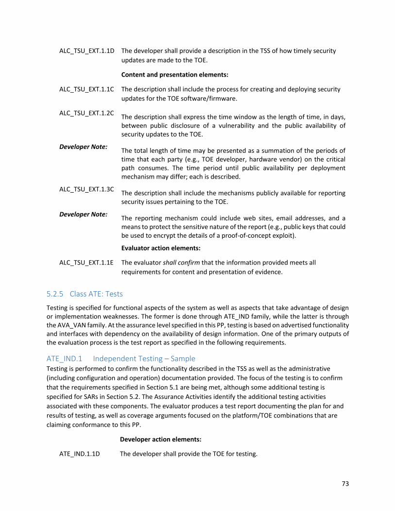
73
ALC_TSU_EXT.1.1D The developer shall provide a description in the TSS of how timely security
updates are made to the TOE.
Content and presentation elements:
ALC_TSU_EXT.1.1C The description shall include the process for creating and deploying security
updates for the TOE software/firmware.
ALC_TSU_EXT.1.2C The description shall express the time window as the length of time, in days, between public disclosure of a vulnerability and the public availability of security updates to the TOE.
Developer Note: The total length of time may be presented as a summation of the periods of time that each party (e.g., TOE developer, hardware vendor) on the critical path consumes. The time period until public availability per deployment mechanism may differ; each is described.
ALC_TSU_EXT.1.3C The description shall include the mechanisms publicly available for reporting security issues pertaining to the TOE.
Developer Note: The reporting mechanism could include web sites, email addresses, and a means to protect the sensitive nature of the report (e.g., public keys that could be used to encrypt the details of a proof-of-concept exploit).
Evaluator action elements:
ALC_TSU_EXT.1.1E The evaluator shall confirm that the information provided meets all
requirements for content and presentation of evidence.
5.2.5 Class ATE: Tests
Testing is specified for functional aspects of the system as well as aspects that take advantage of design or implementation weaknesses. The former is done through ATE_IND family, while the latter is through the AVA_VAN family. At the assurance level specified in this PP, testing is based on advertised functionality and interfaces with dependency on the availability of design information. One of the primary outputs of the evaluation process is the test report as specified in the following requirements.
ATE_IND.1 Independent Testing – Sample Testing is performed to confirm the functionality described in the TSS as well as the administrative
(including configuration and operation) documentation provided. The focus of the testing is to confirm
that the requirements specified in Section 5.1 are being met, although some additional testing is
specified for SARs in Section 5.2. The Assurance Activities identify the additional testing activities
associated with these components. The evaluator produces a test report documenting the plan for and
results of testing, as well as coverage arguments focused on the platform/TOE combinations that are
claiming conformance to this PP.
Developer action elements:
ATE_IND.1.1D The developer shall provide the TOE for testing.

74
Content and presentation elements:
ATE_IND.1.1C The TOE shall be suitable for testing.
Evaluator action elements:
ATE_IND.1.1E The evaluator shall confirm that the information provided meets all
requirements for content and presentation of evidence.
ATE_IND.1.2E The evaluator shall test a subset of the TSF to confirm that the TSF operates
as specified.
Assurance Activity
The evaluator shall prepare a test plan and report documenting the testing aspects of the system. While it is not necessary to have one test case per test listed in an Assurance Activity, the evaluators must document in the test plan that each applicable testing requirement in the ST is covered.
The Test Plan identifies the platforms to be tested, and for those platforms not included in the test plan but included in the ST, the test plan provides a justification for not testing the platforms. This justification must address the differences between the tested platforms and the untested platforms, and make an argument that the differences do not affect the testing to be performed. It is not sufficient to merely assert that the differences have no affect; rationale must be provided. If all platforms claimed in the ST are tested, then no rationale is necessary.
The test plan describes the composition of each platform to be tested, and any setup that is necessary beyond what is contained in the AGD documentation. It should be noted that the evaluators are expected to follow the AGD documentation for installation and setup of each platform either as part of a test or as a standard pre-test condition. This may include special test drivers or tools. For each driver or tool, an argument (not just an assertion) is provided that the driver or tool will not adversely affect the performance of the functionality by the TOE and its platform. This also includes the configuration of cryptographic engines to be used. The cryptographic algorithms implemented by these engines are those specified by this PP and used by the cryptographic protocols being evaluated (IPsec, TLS/HTTPS, SSH).
The test plan identifies high-level test objectives as well as the test procedures to be followed to achieve those objectives. These procedures include expected results. The test report (which could just be an annotated version of the test plan) details the activities that took place when the test procedures were executed, and includes the actual results of the tests. This shall be a cumulative account, so if there was a test run that resulted in a failure; a fix installed; and then a successful re-run of the test, the report would show a “fail” and “pass” result (and the supporting details), and not just the “pass” result.

75
5.2.6 Class AVA: Vulnerability Assessment
For the first generation of this Protection Profile, the evaluation lab is expected to survey open sources to learn what vulnerabilities have been discovered in these types of products. In most cases, these vulnerabilities will require sophistication beyond that of a basic attacker. Until penetration tools are created and uniformly distributed to the evaluation labs, evaluators will not be expected to test for these vulnerabilities in the TOE. The labs will be expected to comment on the likelihood of these vulnerabilities given the documentation provided by the vendor. This information will be used in the development of penetration testing tools and for the development of future PPs.
AVA_VAN.1 Vulnerability Survey Developer action elements:
AVA_VAN.1.1D The developer shall provide the TOE for testing.
Content and presentation elements:
AVA_VAN.1.1C The TOE shall be suitable for testing.
Evaluator action elements:
AVA_VAN.1.1E The evaluator shall confirm that the information provided meets all
requirements for content and presentation of evidence.
AVA_VAN.1.2E The evaluator shall perform a search of public domain sources to
identify potential vulnerabilities in the TOE.
AVA_VAN.1.3E The evaluator shall conduct penetration testing, based on the
identified potential vulnerabilities, to determine that the TOE is
resistant to attacks performed by an attacker possessing Basic attack
potential.
Assurance Activity
As with ATE_IND the evaluator shall generate a report to document their findings with respect to this requirement. This report could physically be part of the overall test report mentioned in ATE_IND, or a separate document. The evaluator performs a search of public information to determine the vulnerabilities that have been found in virtualization in general, as well as those that pertain to the particular TOE. The evaluator documents the sources consulted and the vulnerabilities found in the report. For each vulnerability found, the evaluator either provides a rationale with respect to its non-applicability or the evaluator formulates a test (using the guidelines provided in ATE_IND) to confirm the vulnerability, if suitable. Suitability is determined by assessing the attack vector needed to take advantage of the vulnerability. For example, if the vulnerability can be detected by pressing a key combination on boot-up, a test would be suitable at the assurance level of this PP. If exploiting the vulnerability requires expert skills and an electron microscope, for instance, then a test would not be suitable and an appropriate justification would be formulated.

76

77
Annex A. Optional Requirements
As indicated in Section 2, the baseline requirements (those that must be performed by the TOE) are contained in the body of this PP. Additionally, there are three other types of requirements specified in Appendix A, Appendix B, and Appendix C. The first type (in this Appendix) are requirements that can be included in the ST, but are not required in order for a TOE to claim conformance to this PP. The second type (in Appendix B) are requirements based on selections in the body of the PP: if certain selections are made, then additional requirements in that appendix must be included. The third type (in Appendix C) are components that are not required in order to conform to this PP, but will be included in the baseline requirements in future versions of this PP, so adoption by vendors is encouraged. Note that the ST author is responsible for ensuring that requirements that may be associated with those in Appendix A, Appendix B, and Appendix C but are not listed (e.g., FMT-type requirements) are also included in the ST.
FAU_ARP.1 Security Audit Automatic Response FAU_ARP.1.1 The TSF shall take [assignment: list of actions] upon detection of a potential
security violation.
Application Note: In certain cases, it may be useful for Virtualization Systems to perform
automated responses to certain security events. An example may include halting
a VM which has taken some action to violate a key system security policy. This
may be especially useful with headless endpoints when there is no human user in
the loop.
The potential security violation mentioned in FAU_ARP.1.1 refers to FAU_SAA.1.
Assurance Activity
The evaluator shall generate a potential security violation as defined in FAU_SAA.1 and verify that each action in the assignment in FAU_ARP.1.1 is performed by the TSF as a result. The evaluator shall perform this action for each security violation that is defined in FAU_SAA.1.
FAU_SAA.1 Security Audit Analysis FAU_SAA.1.1 The TSF shall be able to apply a set of rules in monitoring the audited events and
based upon these rules indicate a potential violation of the enforcement of the
SFRs.
FAU_SAA.1.2 The TSF shall enforce the following rules for monitoring audited events:
a) accumulation or combination of [assignment: subset of defined
auditable events] known to indicate a potential security violation,
b) [assignment: any other rules]
Application Note: The potential security violation described in FAU_SAA.1 can be used as a trigger
for automated responses as defined in FAU_ARP.1.
Assurance Activity

78
The evaluator shall cause each combination of auditable events defined in FAU_SAA.1.2 to occur, and verify that a potential security violation is indicated by the TSF.
FPT_GVI_EXT.1 Guest VM Integrity FPT_GVI_EXT.1.1 The TSF shall verify the integrity of Guest VMs through the following
mechanisms: [assignment: list of Guest VM integrity mechanisms].
Application Note: The primary purpose of this requirement is to identify and describe the mechanisms used to verify the integrity of Guest VMs that have been 'imported' in some fashion, though these mechanisms could also be applied to all Guest VMs, depending on the mechanism used. Importation for this requirement could include VM migration (live or otherwise), the importation of virtual disk files that were previously exported, VMs in shared storage, etc. It is possible that a trusted VM could have been modified during the migration or import/export process, or VMs could have been obtained from untrusted sources in the first place, so integrity checks on these VMs can be a prudent measure to take. These integrity checks could be as thorough as making sure the entire VM exactly matches a previously known VM (by hash for example), or by simply checking certain configuration settings to ensure that the VM's configuration will not violate the security model of the VS.
Assurance Activity
For each mechanism listed in the assignment, the evaluator shall ensure that the TSS documents the mechanism, including how it verifies VM integrity, which set of Guest VMs it will check (all Guest VMs, only migrated VMs, etc.), when such checks occur (before VM startup, immediately following importation/migration, on demand, etc.), and which actions are taken if a VM fails the integrity check (or which range of actions are possible if the action is configurable).
Auditable Events Depending on the specific requirements selected by the ST author, the ST/TOE should include the
appropriate auditable events from the table below in the ST as part of the FAU_GEN.1 claim.
Table 2: Auditable Events
Requirement Auditable Events Additional Audit Record Contents
FAU_ARP.1 151 Actions taken due to potential security violations
152 None.
FAU_SAA.1 153 Enabling and disabling of any of the analysis mechanisms
154 Automated responses performed by the TSF
155 None.

79
FPT_GVI.1 156 Actions taken due to failed integrity check.
157 None.

80
Annex B. Selection-Based Requirements
As indicated in the introduction to this PP, the baseline requirements (those that must be performed by the TOE or its underlying platform) are contained in the body of the PP. There are additional requirements based on selections in the body of the PP: if certain selections are made, then additional requirements below will need to be included.
FAU_GEN.1 Auditable Events Table (Optional) The following additional auditable events shall be claimed by the ST author if “additional information
defined in Table 3” is selected in FAU_GEN.1:
Table 3: Auditable Events
Requirement Auditable Events Additional Audit Record Contents
FIA_UIA_EXT.1 158 Administrator session start time and end time
159 None.
FCS_HTTPS_EXT.1 HTTPS Protocol FCS_HTTPS_EXT.1.1 The TSF shall implement the HTTPS protocol that complies with RFC 2818.
Application Note: The ST author must provide enough detail to determine how the implementation
is complying with the standard(s) identified; this can be done either by adding
elements to this component, or by additional detail in the TSS.
FCS_HTTPS_EXT.1.2 The TSF shall implement HTTPS using TLS.
Assurance Activity
The evaluator shall check the TSS to ensure that it is clear on how HTTPS uses TLS to establish an administrative session, focusing on any client authentication required by the TLS protocol vs. security administrator authentication which may be done at a different level of the processing stack. Testing for this activity is done as part of the TLS testing; this may result in additional testing if the TLS tests are done at the TLS protocol level.
FCS_IPSEC_EXT.1 IPsec Protocol FCS_IPSEC_EXT.1.1 The TSF shall implement the IPsec architecture as specified in RFC 4301.
Application Note: RFC 4301 calls for an IPsec implementation to protect IP traffic through the use
of a Security Policy Database (SPD). The SPD is used to define how IP packets are
to be handled: PROTECT the packet (e.g., encrypt the packet), BYPASS the IPsec
services (e.g., no encryption), or DISCARD the packet (e.g., drop the packet). The
SPD can be implemented in various ways, including router access control lists,
firewall rulesets, a “traditional” SPD, etc. Regardless of the implementation
details, there is a notion of a “rule” that a packet is “matched” against and a
resulting action that takes place.
While there must be a means to order the rules, a general approach to ordering
is not mandated, as long as the SPD can distinguish the IP packets and apply the

81
rules accordingly. There may be multiple SPDs (one for each network interface),
but this is not required.
Assurance Activity
The evaluator shall examine the TSS and determine that it describes what takes place when a packet is processed by the TOE, e.g., the algorithm used to process the packet. The TSS describes how the SPD is implemented and the rules for processing both inbound and outbound packets in terms of the IPsec policy. The TSS describes the rules that are available and the resulting actions available after matching a rule. The TSS describes how those rules and actions form the SPD in terms of the BYPASS (e.g., no encryption), DISCARD (e.g., drop the packet), and PROTECT (e.g., encrypt the packet) actions defined in RFC 4301.
As noted in section 4.4.1 of RFC 4301, the processing of entries in the SPD is non-trivial and the evaluator shall determine that the description in the TSS is sufficient to determine which rules will be applied given the rule structure implemented by the TOE. For example, if the TOE allows specification of ranges, conditional rules, etc., the evaluator shall determine that the description of rule processing (for both inbound and outbound packets) is sufficient to determine the action that will be applied, especially in the case where two different rules may apply. This description shall cover both the initial packets (that is, no SA is established on the interface or for that particular packet) as well as packets that are part of an established SA.
Operational Guidance
The evaluator shall examine the operational guidance to verify it instructs the Administrator how to construct entries into the SPD that specify a rule for processing a packet. The description includes all three cases – a rule that ensures packets are encrypted/decrypted, dropped, and flow through the TOE without being encrypted. The evaluator shall determine that the description in the operational guidance is consistent with the description in the TSS, and that the level of detail in the operational guidance is sufficient to allow the administrator to set up the SPD in an unambiguous fashion. This includes a discussion of how ordering of rules impacts the processing of an IP packet.
Tests
The evaluator uses the operational guidance to configure the TOE to carry out the following tests:
Test 1: The evaluator shall configure the SPD such that there is a rule for dropping a packet, encrypting a packet, and allowing a packet to flow in plaintext. The selectors used in the construction of the rule shall be different such that the evaluator can generate a packet and send packets to the gateway with the appropriate fields (fields that are used by the rule - e.g., the IP addresses, TCP/UDP ports) in the packet header. The evaluator performs both positive and negative test cases for each type of rule (e.g., a packet that matches the rule and another that does not match the rule). The evaluator observes via the audit

82
trail, and packet captures that the TOE exhibited the expected behavior: appropriate packets were dropped, allowed to flow without modification, encrypted by the IPsec implementation.
Test 2: The evaluator shall devise several tests that cover a variety of scenarios for packet processing. As with Test 1, the evaluator ensures both positive and negative test cases are constructed. These scenarios shall exercise the range of possibilities for SPD entries and processing modes as outlined in the TSS and operational guidance. Potential areas to cover include rules with overlapping ranges and conflicting entries, inbound and outbound packets, and packets that establish SAs as well as packets that belong to established SAs. The evaluator shall verify, via the audit trail and packet captures, for each scenario that the expected behavior is exhibited, and is consistent with both the TSS and the operational guidance.
FCS_IPSEC_EXT.1.2 The TSF shall have a nominal, final entry in the SPD that matches anything that
is otherwise unmatched, and discards it.
Assurance Activity
The assurance activity for this element is performed in conjunction with the activities for FCS_IPSEC_EXT.1.1.
Tests
The evaluator uses the operational guidance to configure the TOE to carry out the following tests:
Test 1: The evaluator shall configure the SPD such that there is a rule for dropping a packet, encrypting a packet, and allowing a packet to flow in plaintext. The evaluator may use the SPD that was created for verification of FCS_IPSEC_EXT.1.1. The evaluator shall construct a network packet that matches the rule to allow the packet to flow in plaintext and send that packet. The evaluator should observe that the network packet is passed to the proper destination interface with no modification. The evaluator shall then modify a field in the packet header; such that it no longer matches the evaluator-created entries (there may be a “TOE/platform created” final entry that discards packets that do not match any previous entries). The evaluator sends the packet, and observes that the packet was dropped.
FCS_IPSEC_EXT.1.3 The TSF shall implement transport mode and [selection: tunnel mode, no other
mode].
Assurance Activity
The evaluator checks the TSS to ensure it states that the VPN can be established to operate in tunnel mode and/or transport mode (as identified in FCS_IPSEC_EXT.1.3).

83
Operational Guidance
The evaluator shall confirm that the operational guidance contains instructions on how to configure the connection in each mode selected.
Tests
The evaluator shall perform the following test(s) based on the selections chosen:
Test 1 (conditional): If tunnel mode is selected, the evaluator uses the operational guidance to configure the TOE/platform to operate in tunnel mode and also configures a VPN peer to operate in tunnel mode. The evaluator configures the TOE/platform and the VPN peer to use any of the allowable cryptographic algorithms, authentication methods, etc. to ensure an allowable SA can be negotiated. The evaluator shall then initiate a connection from the TOE/Platform to the VPN peer. The evaluator observes (for example, in the audit trail and the captured packets) that a successful connection was established using the tunnel mode.
Test 2: The evaluator uses the operational guidance to configure the TOE/platform to operate in transport mode and also configures a VPN peer to operate in transport mode. The evaluator configures the TOE/platform and the VPN peer to use any of the allowed cryptographic algorithms, authentication methods, etc. to ensure an allowable SA can be negotiated. The evaluator then initiates a connection from the TOE/platform to connect to the VPN peer. The evaluator observes (for example, in the audit trail and the captured packets) that a successful connection was established using the transport mode.
FCS_IPSEC_EXT.1.4 The TSF shall implement the IPsec protocol ESP as defined by RFC 4303 using
the cryptographic algorithms AES-CBC-128, AES-CBC-256 (both specified by RFC
3602) and [selection: AES-GCM-128 (specified in RFC 4106), AES-GCM-256
(specified in RFC 4106), no other algorithms] together with a Secure Hash
Algorithm (SHA)-based HMAC.
Assurance Activity
The evaluator shall examine the TSS to verify that the algorithms AES-CBC-128 and AES-CBC-256 are implemented. If the ST author has selected either AES-GCM-128 or AES-GCM-256 in the requirement, then the evaluator verifies the TSS describes these as well. In addition, the evaluator ensures that the SHA-based HMAC algorithm conforms to the algorithms specified in FCS_COP.1(4) Cryptographic Operations (for keyed-hash message authentication).
Operational Guidance
The evaluator checks the operational guidance to ensure it provides instructions on how to configure the TOE/platform to use the algorithms, and

84
if either AES-GCM-128 or AES-GCM-256 have been selected the guidance instructs how to use these as well.
Tests
The evaluator shall configure the TOE/platform as indicated in the operational guidance configuring the TOE/platform to use each of the supported algorithms, attempt to establish a connection using ESP, and verify that the attempt succeeds.
FCS_IPSEC_EXT.1.5 The TSF shall implement the protocol: [selection:
IKEv1, using Main Mode for Phase 1 exchanges, as defined in RFCs 2407,
2408, 2409, RFC 4109, [selection: no other RFCs for extended sequence
numbers, RFC 4304 for extended sequence numbers], and [selection: no
other RFCs for hash functions, RFC 4868 for hash functions];
IKEv2 as defined in RFC 5996 and [selection: with no support for NAT
traversal, with mandatory support for NAT traversal as specified in RFC
5996, section 2.23)], and [selection: no other RFCs for hash functions, RFC
4868 for hash functions].
Application Note: If the TOE implements SHA-2 hash algorithms for IKEv1 or IKEv2, the ST author
shall select RFC 4868. If the ST author selects IKEv1, FCS_IPSEC_EXT.1.15 must
also be included in the ST.
Assurance Activity
TSS
The evaluator shall examine the TSS to verify that IKEv1 and/or IKEv2 are implemented. If IKEv1 is claimed, the evaluator shall examine the TSS to ensure that, in the description of the IPsec protocol, it states that aggressive mode is not used for IKEv1 Phase 1 exchanges, and that only main mode is used. It may be that this is a configurable option.
Operational Guidance
The evaluator shall check the operational guidance to ensure it instructs the administrator how to configure the TOE/platform to use IKEv1 and/or IKEv2 (as selected), and uses the guidance to configure the TOE/platform to perform NAT traversal for the following test (if selected). If IKEv1 is claimed and the use of main mode requires configuration of the TOE/platform prior to its operation, the evaluator shall check the operational guidance to ensure that instructions for this configuration are contained within that guidance.
Tests
Tests are performed in conjunction with the other IPsec evaluation activities with the exception of the activities below:
(conditional): If the TOE claims IKEv1, the evaluator shall configure the TOE/platform as indicated in the operational guidance (if applicable) and attempt to establish a connection using an IKEv1 Phase 1 connection in

85
aggressive mode. This attempt should fail. The evaluator should then show that main mode exchanges are supported.
(conditional): The evaluator shall configure the TOE/platform so that it will perform NAT traversal processing as described in the TSS and RFC 5996, section 2.23. The evaluator shall initiate an IPsec connection and determine that the NAT is successfully traversed.
FCS_IPSEC_EXT.1.6 The TSF shall ensure the encrypted payload in the [selection: IKEv1, IKEv2]
protocol uses the cryptographic algorithms AES-CBC-128, AES-CBC-256 as
specified in RFC 3602 and [selection: AES-GCM-128, AES-GCM-256 as specified
in RFC 5282, no other algorithm].
Application Note: AES-GCM-128 and AES-GCM-256 may only be selected if IKEv2 is also selected,
as there is no RFC defining AES-GCM for IKEv1.
Assurance Activity
The evaluator shall ensure the TSS identifies the algorithms used for encrypting the IKEv1 and/or IKEv2 payload, and that the algorithms AES-CBC-128, AES-CBC-256 are specified, and if others are chosen in the selection of the requirement, those are included in the TSS discussion.
Operational Guidance
The evaluator ensures that the operational guidance describes the configuration of the mandated algorithms, as well as any additional algorithms selected in the requirement. The guidance is then used to configure the TOE/platform to perform the following test for each ciphersuite selected.
Tests
The evaluator shall configure the TOE/platform to use the ciphersuite under test to encrypt the IKEv1 and/or IKEv2 payload and establish a connection with a peer device, which is configured to only accept the payload encrypted using the indicated ciphersuite. The evaluator will confirm the algorithm was that used in the negotiation.
FCS_IPSEC_EXT.1.7 The TSF shall ensure that [selection:
IKEv1 Phase 1 SA lifetimes can be configured by an Administrator based on
[selection:
o number of packets/bytes;
o length of time, where the time values can be configured within
[assignment: integer range including 24] hours
];
IKEv2 SA lifetimes can be configured by an Administrator based on
[selection:
o number of packets/bytes;

86
o length of time, where the time values can be configured within
[assignment: integer range including 24] hours
]
].
Application Note: The ST author chooses either the IKEv1 requirements or IKEv2 requirements (or
both, depending on the selection in FCS_IPSEC_EXT.1.5). The ST author chooses
either packet/volume-based lifetimes or time-based lifetimes. This requirement
must be accomplished by providing Security Administrator-configurable lifetimes
(with appropriate instructions in documents mandated by AGD_OPE).
Hardcoded limits are not acceptable. In general, instructions for setting the
parameters of the implementation, including lifetime of the SAs, should be
included in the operational guidance generated for AGD_OPE.
Assurance Activity
Operational Guidance
The evaluator shall verify that the values for SA lifetimes can be configured and that the instructions for doing so are located in the operational guidance. If time-based limits are supported, the evaluator ensures that the Administrator is able to configure Phase 1 SA values for 24 hours. Currently there are no values mandated for the number of packets or number of bytes, the evaluator just ensures that this can be configured if selected in the requirement.
Tests
When testing this functionality, the evaluator needs to ensure that both sides are configured appropriately. From the RFC “A difference between IKEv1 and IKEv2 is that in IKEv1 SA lifetimes were negotiated. In IKEv2, each end of the SA is responsible for enforcing its own lifetime policy on the SA and rekeying the SA when necessary. If the two ends have different lifetime policies, the end with the shorter lifetime will end up always being the one to request the rekeying. If the two ends have the same lifetime policies, it is possible that both will initiate a rekeying at the same time (which will result in redundant SAs). To reduce the probability of this happening, the timing of rekeying requests SHOULD be jittered.”
Each of the following tests shall be performed for each version of IKE selected in the FCS_IPSEC_EXT.1.5 protocol selection:
Test 1 (Conditional): The evaluator shall configure a maximum lifetime in terms of the number of packets (or bytes) allowed following the operational guidance. The evaluator shall configure a test peer with a packet/byte lifetime that exceeds the lifetime of the TOE. The evaluator shall establish an SA between the TOE and the test peer, and determine that once the allowed number of packets (or bytes) through this SA is exceeded, a new SA is negotiated. The evaluator shall verify that the TOE initiates a Phase 1 negotiation.

87
Test 2 (Conditional): The evaluator shall configure a maximum lifetime of 24 hours for the Phase 1 SA following the operational guidance. The evaluator shall configure a test peer with a lifetime that exceeds the lifetime of the TOE. The evaluator shall establish an SA between the TOE and the test peer, maintain the Phase 1 SA for 24 hours, and determine that once 24 hours has elapsed, a new Phase 1 SA is negotiated. The evaluator shall verify that the TOE initiates a Phase 1 negotiation.
FCS_IPSEC_EXT.1.8 The TSF shall ensure that [selection:
IKEv1 Phase 2 SA lifetimes can be configured by an Administrator based on
[selection:
o number of packets/bytes;
o length of time, where the time values can be configured within
[assignment: integer range including 8] hours
];
IKEv2 Child SA lifetimes can be configured by an Administrator based on
[selection:
o number of packets/bytes;
o length of time, where the time values can be configured within
[assignment: integer range including 8] hours
]
].
Application Note: The ST author chooses either the IKEv1 requirements or IKEv2 requirements (or
both, depending on the selection in FCS_IPSEC_EXT.1.5). The ST author chooses
either packet/volume-based lifetimes or time-based lifetimes. This requirement
must be accomplished by providing Security Administrator-configurable lifetimes
(with appropriate instructions in documents mandated by AGD_OPE).
Hardcoded limits are not acceptable. In general, instructions for setting the
parameters of the implementation, including lifetime of the SAs, should be
included in the operational guidance generated for AGD_OPE.
Assurance Activity
Operational Guidance
The evaluator shall verify that the values for SA lifetimes can be configured and that the instructions for doing so are located in the operational guidance. If time-based limits are supported, the evaluator ensures that the Administrator is able to configure Phase 2 SA values for 8 hours. Currently there are no values mandated for the number of packets or number of bytes, the evaluator just ensures that this can be configured if selected in the requirement.
Tests

88
When testing this functionality, the evaluator needs to ensure that both sides are configured appropriately. From the RFC “A difference between IKEv1 and IKEv2 is that in IKEv1 SA lifetimes were negotiated. In IKEv2, each end of the SA is responsible for enforcing its own lifetime policy on the SA and rekeying the SA when necessary. If the two ends have different lifetime policies, the end with the shorter lifetime will end up always being the one to request the rekeying. If the two ends have the same lifetime policies, it is possible that both will initiate a rekeying at the same time (which will result in redundant SAs). To reduce the probability of this happening, the timing of rekeying requests SHOULD be jittered.”
Each of the following tests shall be performed for each version of IKE selected in the FCS_IPSEC_EXT.1.5 protocol selection:
Test 1 (Conditional): The evaluator shall configure a maximum lifetime in terms of the number of packets (or bytes) allowed following the operational guidance. The evaluator shall configure a test peer with a packet/byte lifetime that exceeds the lifetime of the TOE. The evaluator shall establish an SA between the TOE and the test peer, and determine that once the allowed number of packets (or bytes) through this SA is exceeded, a new SA is negotiated. The evaluator shall verify that the TOE initiates a Phase 2 negotiation.
Test 2 (Conditional): The evaluator shall configure a maximum lifetime of 8 hours for the Phase 2 SA following the operational guidance. The evaluator shall configure a test peer with a lifetime that exceeds the lifetime of the TOE. The evaluator shall establish an SA between the TOE and the test peer, maintain the Phase 1 SA for 8 hours, and determine that once 8 hours has elapsed, a new Phase 2 SA is negotiated. The evaluator shall verify that the TOE initiates a Phase 2 negotiation.
FCS_IPSEC_EXT.1.9 The TSF shall generate the secret value x used in the IKE Diffie-Hellman key
exchange (“x” in g^x mod p) using the random bit generator specified in
FCS_RBG_EXT.1, and having a length of at least [assignment: (one or more)
number(s) of bits that is at least twice the security strength of the negotiated
Diffie-Hellman group] bits.
Application Note: For DH groups 19 and 20, the "x" value is the point multiplier for the generator
point G.
Since the implementation may allow different Diffie-Hellman groups to be
negotiated for use in forming the SAs, the assignment in FCS_IPSEC_EXT.1.9 may
contain multiple values. For each DH group supported, the ST author consults
Table 2 in NIST SP 800-57 “Recommendation for Key Management –Part 1:
General” to determine the security strength (“bits of security”) associated with
the DH group. Each unique value is then used to fill in the assignment. For
example, suppose the implementation supports DH group 14 (2048-bit MODP)

89
and group 20 (ECDH using NIST curve P-384). From Table 2, the bits of security
value for group 14 is 112, and for group 20 it is 192.
Assurance Activity
The evaluator shall check to ensure that, for each DH group supported, the TSS describes the process for generating "x" (as defined in FCS_IPSEC_EXT.1.). The evaluator shall verify that the TSS indicates that the random number generated that meets the requirements in this PP is used, and that the length of "x" meets the stipulations in the requirement.
FCS_IPSEC_EXT.1.10 The TSF shall generate nonces used in [selection: IKEv1, IKEv2] exchanges of
length [selection:
[assignment: security strength associated with the negotiated Diffie-Hellman
group];
at least 128 bits in size and at least half the output size of the negotiated
pseudorandom function (PRF) hash].
Application Note: The ST author must select the second option for nonce lengths if IKEv2 is also
selected (as this is mandated in RFC 5996). The ST author may select either
option for IKEv1.
For the first option for nonce lengths, since the implementation may allow
different Diffie-Hellman groups to be negotiated for use in forming the SAs, the
assignment in FCS_IPSEC_EXT.1. may contain multiple values. For each DH group
supported, the ST author consults Table 2 in NIST SP 800-57 “Recommendation
for Key Management –Part 1: General” to determine the security strength (“bits
of security”) associated with the DH group. Each unique value is then used to fill
in the assignment. For example, suppose the implementation supports DH group
14 (2048-bit MODP) and group 20 (ECDH using NIST curve P-384). From Table 2,
the bits of security value for group 14 is 112, and for group 20 it is 192.
Because nonces may be exchanged before the DH group is negotiated, the nonce
used should be large enough to support all TOE-chosen proposals in the
exchange.
Assurance Activity
Tests
(conditional) If the first selection is chosen, the evaluator shall check to ensure that, for each DH group supported, the TSS describes the process for generating each nonce. The evaluator shall verify that the TSS indicates that the random number generated that meets the requirements in this PP is used, and that the length of the nonces meet the stipulations in the requirement.
(conditional) If the second selection is chosen, the evaluator shall check to ensure that, for each PRF hash supported, the TSS describes

90
the process for generating each nonce. The evaluator shall verify that the TSS indicates that the random number generated that meets the requirements in this PP is used, and that the length of the nonces meet the stipulations in the requirement.
FCS_IPSEC_EXT.1.11 The TSF shall ensure that all IKE protocols implement DH Groups 14 (2048-bit
MODP), and [selection: 19 (256-bit Random ECP), 5 (1536-bit MODP), 24 (2048-
bit MODP with 256-bit POS), 20 (384-bit Random ECP), no other DH groups].
Application Note: The selection is used to specify additional DH groups supported. This applies to
IKEv1 and IKEv2 exchanges. It should be noted that if any additional DH groups
are specified, they must comply with the requirements (in terms of the
ephemeral keys that are established) listed in FCS_CKM.1.
Assurance Activity
The evaluator shall check to ensure that the DH groups specified in the requirement are listed as being supported in the TSS. If there is more than one DH group supported, the evaluator checks to ensure the TSS describes how a particular DH group is specified/negotiated with a peer.
Tests
For each supported DH group, the evaluator shall test to ensure that all supported IKE protocols can be successfully completed using that particular DH group.
FCS_IPSEC_EXT.1.12 The TSF shall be able to ensure by default that the strength of the symmetric
algorithm (in terms of the number of bits in the key) negotiated to protect the
[selection: IKEv1 Phase 1, IKEv2 IKE_SA] connection is greater than or equal to
the strength of the symmetric algorithm (in terms of the number of bits in the
key) negotiated to protect the [selection: IKEv1 Phase 2, IKEv2 CHILD_SA]
connection.
Application Note: The ST author chooses either or both of the IKE selections based on what is
implemented by the TOE. Obviously, the IKE version(s) chosen should be
consistent not only in this element, but with other choices for other elements in
this component. While it is acceptable for this capability to be configurable, the
default configuration in the evaluated configuration (either "out of the box" or
by configuration guidance in the AGD documentation) must enable this
functionality.
Assurance Activity
The evaluator shall check that the TSS describes the potential strengths (in terms of the number of bits in the symmetric key) of the algorithms that are allowed for the IKE and ESP exchanges. The TSS shall also describe the checks that are done when negotiating IKEv1 Phase 2 and/or IKEv2 CHILD_SA suites to ensure that the strength (in terms of the number of bits of key in the symmetric

91
algorithm) of the negotiated algorithm is less than or equal to that of the IKE SA this is protecting the negotiation.
Tests
The evaluator simply follows the guidance to configure the TOE/platform to perform the following tests.
Test 1: This test shall be performed for each version of IKE supported. The evaluator shall successfully negotiate an IPsec connection using each of the supported algorithms and hash functions identified in the requirements.
Test 2: This test shall be performed for each version of IKE supported. The evaluator shall attempt to establish an SA for ESP that selects an encryption algorithm with more strength than that being used for the IKE SA (i.e., symmetric algorithm with a key size larger than that being used for the IKE SA). Such attempts should fail.
Test 3: This test shall be performed for each version of IKE supported. The evaluator shall attempt to establish an IKE SA using an algorithm that is not one of the supported algorithms and hash functions identified in the requirements. Such an attempt should fail.
Test 4: This test shall be performed for each version of IKE supported. The evaluator shall attempt to establish an SA for ESP (assumes the proper parameters where used to establish the IKE SA) that selects an encryption algorithm that is not identified in FCS_IPSEC_EXT.1.4. Such an attempt should fail.
FCS_IPSEC_EXT.1.13 The TSF shall ensure that all IKE protocols perform peer authentication using a
[selection: RSA, ECDSA] that use X.509v3 certificates that conform to RFC 4945
and [selection: Pre-shared Keys, no other method].
Application Note: At least one public-key-based Peer Authentication method is required in order to
conform to this PP; one or more of the public key schemes is chosen by the ST
author to reflect what is implemented. The ST author also ensures that
appropriate FCS requirements reflecting the algorithms used (and key
generation capabilities, if provided) are listed to support those methods. Note
that the TSS will elaborate on the way in which these algorithms are to be used
(for example, 2409 specifies three authentication methods using public keys;
each one supported will be described in the TSS).
Assurance Activity
The evaluator ensures that the TSS identifies RSA and/or ECDSA as being used to perform peer authentication. The description shall be consistent with the algorithms as specified in FCS_COP.1(2) Cryptographic Operations (for cryptographic signature).
If pre-shared keys are chosen in the selection, the evaluator shall check to ensure that the TSS describes how pre-shared keys are established and used in

92
authentication of IPsec connections. The evaluator shall check that the operational guidance describes how pre-shared keys are to be generated and established. The description in the TSS and the operational guidance shall also indicate how pre-shared key establishment is accomplished for TOEs that can generate a pre-shared key as well as TOEs that simply use a pre-shared key.
Operational Guidance
The evaluator ensures the operational guidance describes how to set up the TOE to use certificates with RSA and/or ECDSA signatures and public keys.
In order to construct the environment and configure the TOE for the following tests, the evaluator will ensure that the operational guidance describes how to configure the TOE to connect to a trusted CA, and ensure a valid certificate for that CA is loaded into the TOE and marked “trusted”.
Tests
For efficiency sake, the testing that is performed may be combined with the testing for FIA_X509_EXT.1, FIA_X509_EXT.2 (for IPsec connections), and FCS_IPSEC_EXT.1.1. The following tests shall be repeated for each peer authentication selected in the FCS_IPSEC_EXT.1.1 selection above:
Test 1: The evaluator shall configure the TOE to use a private key and associated certificate signed by a trusted CA and shall establish an IPsec connection with the peer.
Test 2 [conditional]: The evaluator shall generate a pre-shared key off-TOE and use it, as indicated in the operational guidance, to establish an IPsec connection with the peer.
FCS_IPSEC_EXT.1.14 The TSF shall support peer identifiers of the following types: [selection: IP
address, Fully Qualified Domain Name (FQDN), user FQDN, Distinguished Name
(DN)] and [selection: no other reference identifier type, [assignment: other
supported reference identifier types]].
Application Note: The TOE must support at least one of the following identifier types: IP address,
Fully Qualified Domain Name (FQDN), user FQDN, or Distinguished Name (DN).
In the future, the TOE will be required to support all of these identifier types. The
TOE is expected to support as many IP address formats (IPv4 and IPv6) as IP
versions supported by the TOE in general. The ST author may assign additional
supported identifier types in the second selection.
Assurance Activity
13 The assurance activities for this element are performed in conjunction with the assurance activities for the next element.
FCS_IPSEC_EXT.1.15 The TSF shall not establish an SA if the presented identifier does not match the
configured reference identifier of the peer.

93
Application Note: At this time, only the comparison between the presented identifier in the peer’s
certificate and the peer’s reference identifier is mandated by the testing below.
However, in the future, this requirement will address two aspects of the peer
certificate validation: 1) comparison of the peer’s ID payload to the peer’s
certificate which are both presented identifiers, as required by RFC 4945 and 2)
verification that the peer identified by the ID payload and the certificate is the
peer expected by the TOE (per the reference identifier). At that time, the TOE will
be required to demonstrate both aspects (i.e. that the TOE enforces that the
peer’s ID payload matches the peer’s certificate which both match configured
peer reference identifiers).
Excluding the DN identifier type (which is necessarily the Subject DN in the peer
certificate), the TOE may support the identifier in either the Common Name or
Subject Alternative Name (SAN) or both. If both are supported, the preferred
logic is to compare the reference identifier to a presented SAN, and only if the
peer’s certificate does not contain a SAN, to fall back to a comparison against
the Common Name. In the future, the TOE will be required to compare the
reference identifier to the presented identifier in the SAN only, ignoring the
Common Name.
The configuration of the peer reference identifier is addressed by FMT_SMF.1.1.
Assurance Activity
14 TSS
15 The evaluator shall ensure that the TSS describes how the TOE compares the peer’s presented identifier to the reference identifier. This description shall include whether the certificate presented identifier is compared to the ID payload presented identifier, which field(s) of the certificate are used as the presented identifier (DN, Common Name, or SAN), and, if multiple fields are supported, the logical order comparison. If the ST author assigned an additional identifier type, the TSS description shall also include a description of that type and the method by which that type is compared to the peer’s presented certificate.
16 Guidance
17 The evaluator shall ensure that the operational guidance includes the configuration of the reference identifier(s) for the peer.
18 Tests
19 For each supported identifier type (excluding DNs), the evaluator shall repeat the following tests:
20 Test 1: For each field of the certificate supported for comparison, the evaluator shall configure the peer’s reference identifier on the TOE (per the administrative guidance) to match the field in the peer’s presented certificate and shall verify that the IKE authentication succeeds.

94
21 Test 2: For each field of the certificate support for comparison, the evaluator shall configure the peer’s reference identifier on the TOE (per the administrative guidance) to not match the field in the peer’s presented certificate and shall verify that the IKE authentication fails.
22 The following tests are conditional:
23 Test 3: (conditional) If, according to the TSS, the TOE supports both Common Name and SAN certificate fields and uses the preferred logic outlined in the Application Note, the tests above with the Common Name field shall be performed using peer certificates with no SAN extension. Additionally, the evaluator shall configure the peer’s reference identifier on the TOE to not match the SAN in the peer’s presented certificate but to match the Common Name in the peer’s presented certificate, and verify that the IKE authentication fails.
24 Test 4: (conditional) If the TOE supports DN identifier types, the evaluator shall configure the peer’s reference identifier on the TOE (per the administrative guidance) to match the subject DN in the peer’s presented certificate and shall verify that the IKE authentication succeeds. To demonstrate a bit-wise comparison of the DN, the evaluator shall change a single bit in the DN (preferably, in an Object Identifier (OID) in the DN) and verify that the IKE authentication fails.
25 Test 5: (conditional) If the TOE supports both IPv4 and IPv6 and supports IP address identifier types, the evaluator must repeat test 1 and 2 with both IPv4 address identifiers and IPv6 identifiers. Additionally, the evaluator shall verify that the TOE verifies that the IP header matches the identifiers by setting the presented identifiers and the reference identifier with the same IP address that differs from the actual IP address of the peer in the IP headers and verifying that the IKE authentication fails.
26 Test 6: (conditional) If, according to the TSS, the TOE performs comparisons between the peer’s ID payload and the peer’s certificate, the evaluator shall repeat the following test for each combination of supported identifier types and supported certificate fields (as above). The evaluator shall configure the peer to present a different ID payload than the field in the peer’s presented certificate and verify that the TOE fails to authenticate the IKE peer.
FCS_TLSC_EXT.1 TLS Client Protocol FCS_TLSC_EXT.1.1 The TSF shall implement [selection: TLS 1.2 (RFC 5246), TLS 1.1 (RFC 4346)]
supporting the following ciphersuites:
● Mandatory Ciphersuites:
o TLS_RSA_WITH_AES_128_CBC_SHA as defined in RFC 3268
● Optional Ciphersuites: [selection:
o TLS_RSA_WITH_AES_256_CBC_SHA as defined in RFC 3268
o TLS_DHE_RSA_WITH_AES_128_CBC_SHA as defined in RFC 3268
o TLS_DHE_RSA_WITH_AES_256_CBC_SHA as defined in RFC 3268

95
o TLS_ECDHE_RSA_WITH_AES_128_CBC_SHA as defined in RFC 4492
o TLS_ECDHE_RSA_WITH_AES_256_CBC_SHA as defined in RFC 4492
o TLS_ECDHE_ECDSA_WITH_AES_128_CBC_SHA as defined in RFC 4492
o TLS_ECDHE_ECDSA_WITH_AES_256_CBC_SHA as defined in RFC 4492
o TLS_RSA_WITH_AES_128_CBC_SHA256 as defined in RFC 5246
o TLS_RSA_WITH_AES_256_CBC_ SHA256 as defined in RFC 5246
o TLS_DHE_RSA_WITH_AES_128_CBC_ SHA256 as defined in RFC 5246
o TLS_DHE_RSA_WITH_AES_256_CBC_ SHA256 as defined in RFC 5246
o TLS_ECDHE_ECDSA_WITH_AES_128_CBC_SHA256 as defined in RFC
5289
o TLS_ECDHE_ECDSA_WITH_AES_256_CBC_SHA384 as defined in RFC
5289
o TLS_ECDHE_ECDSA_WITH_AES_128_GCM_SHA256 as defined in RFC
5289
o TLS_ECDHE_ECDSA_WITH_AES_256_GCM_SHA384 as defined in RFC
5289
o TLS_ECDHE_RSA_WITH_AES_128_GCM_SHA256 as defined in RFC 5289
o TLS_ECDHE_RSA_WITH_AES_256_GCM_SHA384 as defined in RFC 5289
o no other ciphersuite].
Application Note: The ciphersuites to be tested in the evaluated configuration are limited by this requirement. The ST author should select the optional ciphersuites that are supported; if there are no ciphersuites supported other than the mandatory suites, then “None” should be selected. It is necessary to limit the ciphersuites that can be used in an evaluated configuration administratively on the server in the test environment. The Suite B algorithms listed above (RFC 6460) are the preferred algorithms for implementation. TLS_RSA_WITH_AES_128_CBC_SHA is required in order to ensure compliance with RFC 5246.
These requirements will be revisited as new TLS versions are standardized by the IETF.
If any ciphersuites are selected using ECDHE, then FCS_TLSC_EXT.1.5 is required.
In a future version of this PP TLS v1.2 will be required for all TOEs.
Assurance Activity
The evaluator shall check the description of the implementation of this protocol in the TSS to ensure that the ciphersuites supported are specified. The evaluator shall check the TSS to ensure that the ciphersuites specified include those listed for this component.
Tests
Test 1: The evaluator shall establish a TLS connection using each of the ciphersuites specified by the requirement. This connection may be established as part of the establishment of a higher-level protocol, e.g., as part of an EAP

96
session. It is sufficient to observe the successful negotiation of a ciphersuite to satisfy the intent of the test; it is not necessary to examine the characteristics of the encrypted traffic in an attempt to discern the ciphersuite being used (for example, that the cryptographic algorithm is 128-bit AES and not 256-bit AES).
Test 2: The evaluator shall attempt to establish the connection using a server with a server certificate that contains the Server Authentication purpose in the extendedKeyUsage field and verify that a connection is established. The evaluator will then verify that the client rejects an otherwise valid server certificate that lacks the Server Authentication purpose in the extendedKeyUsage field and a connection is not established. Ideally, the two certificates should be identical except for the extendedKeyUsage field.
Test 3: The evaluator shall send a server certificate in the TLS connection that the does not match the server-selected ciphersuite (for example, send a ECDSA certificate while using the TLS_RSA_WITH_AES_128_CBC_SHA ciphersuite or send a RSA certificate while using one of the ECDSA ciphersuites.) The evaluator shall verify that the TOE disconnects after receiving the server’s Certificate handshake message.
Test 4: The evaluator shall configure the server to select the TLS_NULL_WITH_NULL_NULL ciphersuite and verify that the client denies the connection.
Test 5: The evaluator shall perform the following modifications to the traffic:
Change the TLS version selected by the server in the Server Hello to a non-supported TLS version (for example 1.3 represented by the two bytes 03 04) and verify that the client rejects the connection.
Modify at least one byte in the server’s nonce in the Server Hello handshake message, and verify that the client rejects the Server Key Exchange handshake message (if using a DHE or ECDHE ciphersuite) or that the server denies the client’s Finished handshake message.
Modify the server’s selected ciphersuite in the Server Hello handshake message to be a ciphersuite not presented in the Client Hello handshake message. The evaluator shall verify that the client rejects the connection after receiving the Server Hello.
Modify the signature block in the Server’s Key Exchange handshake message, and verify that the client rejects the connection after receiving the Server Key Exchange message.
Modify a byte in the Server Finished handshake message, and verify that the client sends a fatal alert upon receipt and does not send any application data.
Send a garbled message from the Server after the Server has issued the ChangeCipherSpec message and verify that the client denies the connection.

97
FCS_TLSC_EXT.1.2 The TSF shall verify that the presented identifier matches the reference
identifier according to RFC 6125.
Application Note: The rules for verification of identity are described in Section 6 of RFC 6125. The reference identifier is established by the user (e.g., entering a URL into a web browser or clicking a link), by configuration (e.g., configuring the name of a mail server or authentication server), or by an application (e.g., a parameter of an API) depending on the application service. Based on a singular reference identifier’s source domain and application service type (e.g., HTTP, SIP, LDAP), the client establishes all reference identifiers which are acceptable, such as a Common Name for the Subject Name field of the certificate and a (case-insensitive) DNS name, URI name, and Service Name for the Subject Alternative Name field. The client then compares this list of all acceptable reference identifiers to the presented identifiers in the TLS server’s certificate.
The preferred method for verification is the Subject Alternative Name using DNS names, URI names, or Service Names. Verification using the Common Name is required for the purposes of backwards compatibility. Additionally, support for use of IP addresses in the Subject Name or Subject Alternative name is discouraged as against best practices but may be implemented. Finally, the client should avoid constructing reference identifiers using wildcards. However, if the presented identifiers include wildcards, the client must follow the best practices regarding matching; these best practices are captured in the assurance activity.
Assurance Activity
The evaluator shall ensure that the TSS describes the client’s method of establishing all reference identifiers from the administrator/application-configured reference identifier, including which types of reference identifiers are supported (e.g., Common Name, DNS Name, URI Name, Service Name, or other application-specific Subject Alternative Names) and whether IP addresses and wildcards are supported. The evaluator shall ensure that this description identifies whether and the manner in which certificate pinning is supported or used by the TOE.
Tests
The evaluator shall configure the reference identifier according to the AGD guidance and perform the following tests during a TLS connection:
Test 1: The evaluator shall present a server certificate that does not contain an identifier in either the Subject Alternative Name (SAN) or Common Name (CN) that matches the reference identifier. The evaluator shall verify that the connection fails.
Test 2: The evaluator shall present a server certificate that contains a CN that matches the reference identifier, contains the SAN extension, but does not contain an identifier in the SAN that matches the reference identifier. The evaluator shall verify that the connection fails. The evaluator shall repeat this test for each supported SAN type.

98
Test 3: The evaluator shall present a server certificate that contains a CN that matches the reference identifier and does not contain the SAN extension. The evaluator shall verify that the connection succeeds.
Test 4: The evaluator shall present a server certificate that contains a CN that does not match the reference identifier but does contain an identifier in the SAN that matches. The evaluator shall verify that the connection succeeds.
Test 5: The evaluator shall perform the following wildcard tests with each supported type of reference identifier:
The evaluator shall present a server certificate containing a wildcard that is not in the left-most label of the presented identifier (e.g., foo.*.example.com) and verify that the connection fails.
The evaluator shall present a server certificate containing a wildcard in the left-most label (e.g., *.example.com). The evaluator shall configure the reference identifier with a single left-most label (e.g., foo.example.com) and verify that the connection succeeds. The evaluator shall configure the reference identifier without a left-most label as in the certificate (e.g., example.com) and verify that the connection fails. The evaluator shall configure the reference identifier with two left-most labels (e.g., bar.foo.example.come) and verify that the connection fails.
Test 6: [conditional] If URI or Service name reference identifiers are supported, the evaluator shall configure the DNS name and the service identifier. The evaluator shall present a server certificate containing the correct DNS name and service identifier in the URIName or SRVName fields of the SAN and verify that the connection succeeds. The evaluator shall repeat this test with the wrong service identifier (but correct DNS name) and verify that the connection fails.
Test 7: [conditional] If pinned certificates are supported the evaluator shall present a certificate that does not match the pinned certificate and verify that the connection fails.
FCS_TLSC_EXT.1.3 The TSF shall establish a trusted channel only if the peer certificate is valid.
Application Note: Validity is determined by the identifier verification, certificate path, the expiration date, and the revocation status in accordance with RFC 5280. Certificate validity shall be tested in accordance with testing performed for FIA_X509_EXT.1.
Assurance Activity
Tests
Test 1: The evaluator shall demonstrate that using a certificate without a valid certification path results in the function failing. Using the administrative guidance, the evaluator shall then load a certificate or certificates needed to validate the certificate to be used in the function, and demonstrate that the

99
function succeeds. The evaluator then shall delete one of the certificates, and show that the function fails.
FCS_TLSC_EXT.1.4 The TSF shall support mutual authentication using X.509v3 certificates.
Application Note: If TLS is used for FTP_ITC_EXT.1, then this component is required.
The use of X.509v3 certificates for TLS is addressed in FIA_X509_EXT.2.1. This requirement adds that this use must include the client must be capable of presenting a certificate to a TLS server for TLS mutual authentication.
Assurance Activity
The evaluator shall ensure that the TSS description required per FIA_X509_EXT.2.1 includes the use of client-side certificates for TLS mutual authentication.
Tests
Test 1: The evaluator shall perform the following modification to the traffic:
Configure the server to require mutual authentication and then modify a byte in a CA field in the Server’s Certificate Request handshake message. The modified CA field shall not be the CA used to sign the client’s certificate. The evaluator shall verify the connection is unsuccessful.
FCS_TLSC_EXT.1.5 The TSF shall present the Supported Elliptic Curves Extension in the Client Hello
with the following NIST curves: [selection: secp256r1, secp384r1, secp521r1]
and no other curves.
Application Note: If ciphersuites with elliptic curves were selected in FCS_TLSC_EXT.1.1, this component is required.
This requirement limits the elliptic curves allowed for authentication and key agreement to the NIST curves from FCS_COP.1(2) and FCS_CKM.1 and FCS_CKM.2. This extension is required for clients supporting Elliptic Curve ciphersuites.
Assurance Activity
The evaluator shall verify that TSS describes the Supported Elliptic Curves Extension and whether the required behavior is performed by default or may be configured.
Tests
Test 1: The evaluator shall configure the server to perform an ECDHE key exchange in the TLS connection using a non-supported curve (for example P-192) and shall verify that the TOE disconnects after receiving the server’s Key Exchange handshake message.

100
FCS_TLSS_EXT.1 TLS Server Protocol FCS_TLSS_EXT.1.1 The TSF shall implement [selection: TLS 1.2 (RFC 5246), TLS 1.1 (RFC 4346)]
supporting the following ciphersuites:
● Mandatory Ciphersuites:
o TLS_RSA_WITH_AES_128_CBC_SHA as defined in RFC 3268
● Optional Ciphersuites: [selection:
o TLS_RSA_WITH_AES_256_CBC_SHA as defined in RFC 3268
o TLS_DHE_RSA_WITH_AES_128_CBC_SHA as defined in RFC 3268
o TLS_DHE_RSA_WITH_AES_256_CBC_SHA as defined in RFC 3268
o TLS_ECDHE_RSA_WITH_AES_128_CBC_SHA as defined in RFC 4492
o TLS_ECDHE_RSA_WITH_AES_256_CBC_SHA as defined in RFC 4492
o TLS_ECDHE_ECDSA_WITH_AES_128_CBC_SHA as defined in RFC 4492
o TLS_ECDHE_ECDSA_WITH_AES_256_CBC_SHA as defined in RFC 4492
o TLS_RSA_WITH_AES_128_CBC_SHA256 as defined in RFC 5246
o TLS_RSA_WITH_AES_256_CBC_ SHA256 as defined in RFC 5246
o TLS_DHE_RSA_WITH_AES_128_CBC_ SHA256 as defined in RFC 5246
o TLS_DHE_RSA_WITH_AES_256_CBC_ SHA256 as defined in RFC 5246
o TLS_ECDHE_ECDSA_WITH_AES_128_CBC_SHA256 as defined in RFC
5289
o TLS_ECDHE_ECDSA_WITH_AES_256_CBC_SHA384 as defined in RFC
5289
o TLS_ECDHE_ECDSA_WITH_AES_128_GCM_SHA256 as defined in RFC
5289
o TLS_ECDHE_ECDSA_WITH_AES_256_GCM_SHA384 as defined in RFC
5289
o TLS_ECDHE_RSA_WITH_AES_128_GCM_SHA256 as defined in RFC 5289
o TLS_ECDHE_RSA_WITH_AES_256_GCM_SHA384 as defined in RFC 5289
o no other ciphersuite].
Application Note: The ciphersuites to be tested in the evaluated configuration are limited by this requirement. The ST author should select the optional ciphersuites that are supported; if there are no ciphersuites supported other than the mandatory suites, then “None” should be selected. It is necessary to limit the ciphersuites that can be used in an evaluated configuration administratively on the server in the test environment. The Suite B algorithms listed above (RFC 6460) are the preferred algorithms for implementation. TLS_RSA_WITH_AES_128_CBC_SHA is required in order to ensure compliance with RFC 5246.
These requirements will be revisited as new TLS versions are standardized by the IETF.
If any ciphersuites are selected using ECDHE, then FCS_TLSS_EXT.1.5 is required.
In a future version of this PP TLS v1.2 will be required for all TOEs.

101
Assurance Activity
The evaluator shall check the description of the implementation of this protocol in the TSS to ensure that the ciphersuites supported are specified. The evaluator shall check the TSS to ensure that the ciphersuites specified are identical to those listed for this component.
Operational Guidance
The evaluator shall also check the operational guidance to ensure that it contains instructions on configuring the TOE so that TLS conforms to the description in the TSS (for instance, the set of ciphersuites advertised by the TOE may have to be restricted to meet the requirements).
Tests
Test 1: The evaluator shall establish a TLS connection using each of the ciphersuites specified by the requirement. This connection may be established as part of the establishment of a higher-level protocol, e.g., as part of an EAP session. It is sufficient to observe the successful negotiation of a ciphersuite to satisfy the intent of the test; it is not necessary to examine the characteristics of the encrypted traffic in an attempt to discern the ciphersuite being used (for example, that the cryptographic algorithm is 128-bit AES and not 256-bit AES).
Test 2: The evaluator shall send a Client Hello to the server with a list of ciphersuites that does not contain any of the ciphersuites in the server’s ST and verify that the server denies the connection. Additionally, the evaluator shall send a Client Hello to the server containing only the TLS_NULL_WITH_NULL_NULL ciphersuite and verify that the server denies the connection.
Test 3: The evaluator shall use a client to send a key exchange message in the TLS connection that the does not match the server-selected ciphersuite (for example, send an ECDHE key exchange while using the TLS_RSA_WITH_AES_128_CBC_SHA ciphersuite or send a RSA key exchange while using one of the ECDSA ciphersuites.) The evaluator shall verify that the TOE disconnects after the receiving the key exchange message.
Test 4: The evaluator shall perform the following modifications to the traffic:
Modify at a byte in the client’s nonce in the Client Hello handshake message, and verify that the server rejects the client’s Certificate Verify handshake message (if using mutual authentication) or that the server denies the client’s Finished handshake message.
Modify the signature block in the Client’s Key Exchange handshake message, and verify that the server rejects the client’s Certificate Verify handshake message (if using mutual authentication) or that the server denies the client’s Finished handshake message.
Modify a byte in the Client Finished handshake message, and verify that the server rejects the connection and does not send any application data.

102
After generating a fatal alert by sending a Finished message from the client before the client sends a ChangeCipherSpec message, send a Client Hello with the session identifier from the previous test, and verify that the server denies the connection.
Send a garbled message from the client after the client has issued the ChangeCipherSpec message and verify that the Server denies the connection.
FCS_TLSS_EXT.1.2 The TSF shall deny connections from clients requesting SSL 1.0, SSL 2.0, SSL 3.0,
TLS 1.0, and [selection: TLS 1.1, none].
Application Note: All SSL versions and TLS v1.0 shall be denied. Any TLS versions not selected in FCS_TLSS_EXT.1.1 should be selected here.
Assurance Activity
The evaluator shall verify that the TSS contains a description of the denial of old SSL and TLS versions.
Operational Guidance
The evaluator shall verify that any configuration necessary to meet the requirement are contained in the AGD guidance.
Tests
The evaluator shall send a Client Hello requesting a connection with version SSL 1.0 and verify that the server denies the connection. The evaluator shall repeat this test with SSL 2.0, SSL 3.0, TLS 1.0, and any selected TLS versions.
FCS_TLSS_EXT.1.3 The TSF shall generate key agreement parameters using RSA with key size 2048
bits and [selection: 3072 bits, 4096 bits, no other size] and [selection: over NIST
curves [selection: secp256r1, secp384r1] and no other curves; Diffie-Hellman
parameters of size 2048 bits and [selection: 3072 bits, no other size]; no other].
Application Note: If the ST lists a DHE or ECDHE ciphersuite in FCS_TLSS_EXT.1.1, the ST must include the Diffie-Hellman or NIST curves selection in the requirement. FMT_SMF.1 requires the configuration of the key agreement parameters in order to establish the security strength of the TLS connection.
Assurance Activity
The evaluator shall verify that the TSS describes the key agreement parameters of the server key exchange message.
Operational Guidance
The evaluator shall verify that any configuration necessary to meet the requirement is contained in the AGD guidance.
Tests
If the second selection includes any choice other than “no other”, the evaluator shall attempt a connection using an ECDHE ciphersuite and a configured curve

103
and, using a packet analyzer, verify that the key agreement parameters in the Key Exchange message are the ones configured. (Determining that the size matches the expected size for the configured curve is sufficient.) The evaluator shall repeat this test for each supported NIST Elliptic Curve and each supported Diffie-Hellman key size.
FCS_TLSS_EXT.2 TLS Server Protocol with Mutual Authentication FCS_TLSS_EXT.2.1 The TSF shall implement [selection: TLS 1.2 (RFC 5246), TLS 1.1 (RFC 4346)]
supporting the following ciphersuites:
● Mandatory Ciphersuites:
o TLS_RSA_WITH_AES_128_CBC_SHA as defined in RFC 3268
● Optional Ciphersuites: [selection:
o TLS_RSA_WITH_AES_256_CBC_SHA as defined in RFC 3268
o TLS_DHE_RSA_WITH_AES_128_CBC_SHA as defined in RFC 3268
o TLS_DHE_RSA_WITH_AES_256_CBC_SHA as defined in RFC 3268
o TLS_ECDHE_RSA_WITH_AES_128_CBC_SHA as defined in RFC 4492
o TLS_ECDHE_RSA_WITH_AES_256_CBC_SHA as defined in RFC 4492
o TLS_ECDHE_ECDSA_WITH_AES_128_CBC_SHA as defined in RFC 4492
o TLS_ECDHE_ECDSA_WITH_AES_256_CBC_SHA as defined in RFC 4492
o TLS_RSA_WITH_AES_128_CBC_SHA256 as defined in RFC 5246
o TLS_RSA_WITH_AES_256_CBC_ SHA256 as defined in RFC 5246
o TLS_DHE_RSA_WITH_AES_128_CBC_ SHA256 as defined in RFC 5246
o TLS_DHE_RSA_WITH_AES_256_CBC_ SHA256 as defined in RFC 5246
o TLS_ECDHE_ECDSA_WITH_AES_128_CBC_SHA256 as defined in RFC
5289
o TLS_ECDHE_ECDSA_WITH_AES_256_CBC_SHA384 as defined in RFC
5289
o TLS_ECDHE_ECDSA_WITH_AES_128_GCM_SHA256 as defined in RFC
5289
o TLS_ECDHE_ECDSA_WITH_AES_256_GCM_SHA384 as defined in RFC
5289
o TLS_ECDHE_RSA_WITH_AES_128_GCM_SHA256 as defined in RFC 5289
o TLS_ECDHE_RSA_WITH_AES_256_GCM_SHA384 as defined in RFC 5289
o no other ciphersuite].
Application Note: The ciphersuites to be tested in the evaluated configuration are limited by this requirement. The ST author should select the optional ciphersuites that are supported; if there are no ciphersuites supported other than the mandatory suites, then “None” should be selected. It is necessary to limit the ciphersuites that can be used in an evaluated configuration administratively on the server in the test environment. The Suite B algorithms listed above (RFC 6460) are the preferred algorithms for implementation. TLS_RSA_WITH_AES_128_CBC_SHA is required in order to ensure compliance with RFC 5246.

104
These requirements will be revisited as new TLS versions are standardized by the IETF.
If any ciphersuites are selected using ECDHE, then FCS_TLSS_EXT.1.5 is required.
In a future version of this PP TLS v1.2 will be required for all TOEs.
Assurance Activity
The evaluator shall check the description of the implementation of this protocol in the TSS to ensure that the ciphersuites supported are specified. The evaluator shall check the TSS to ensure that the ciphersuites specified are identical to those listed for this component.
Operational Guidance
The evaluator shall also check the operational guidance to ensure that it contains instructions on configuring the TOE so that TLS conforms to the description in the TSS (for instance, the set of ciphersuites advertised by the TOE may have to be restricted to meet the requirements).
Tests
Test 1: The evaluator shall establish a TLS connection using each of the ciphersuites specified by the requirement. This connection may be established as part of the establishment of a higher-level protocol, e.g., as part of an EAP session. It is sufficient to observe the successful negotiation of a ciphersuite to satisfy the intent of the test; it is not necessary to examine the characteristics of the encrypted traffic in an attempt to discern the ciphersuite being used (for example, that the cryptographic algorithm is 128-bit AES and not 256-bit AES).
Test 2: The evaluator shall send a Client Hello to the server with a list of ciphersuites that does not contain any of the ciphersuites in the server’s ST and verify that the server denies the connection. Additionally, the evaluator shall send a Client Hello to the server containing only the TLS_NULL_WITH_NULL_NULL ciphersuite and verify that the server denies the connection.
Test 3: The evaluator shall use a client to send a key exchange message in the TLS connection that the does not match the server-selected ciphersuite (for example, send an ECDHE key exchange while using the TLS_RSA_WITH_AES_128_CBC_SHA ciphersuite or send a RSA key exchange while using one of the ECDSA ciphersuites.) The evaluator shall verify that the TOE disconnects after the receiving the key exchange message.
Test 4: The evaluator shall perform the following modifications to the traffic:
Modify at a byte in the client’s nonce in the Client Hello handshake message, and verify that the server rejects the client’s Certificate Verify handshake message (if using mutual authentication) or that the server denies the client’s Finished handshake message.
Modify the signature block in the Client’s Key Exchange handshake message, and verify that the server rejects the client’s Certificate Verify

105
handshake message (if using mutual authentication) or that the server denies the client’s Finished handshake message.
Modify a byte in the Client Finished handshake message, and verify that the server rejects the connection and does not send any application data.
After generating a fatal alert by sending a Finished message from the client before the client sends a ChangeCipherSpec message, send a Client Hello with the session identifier from the previous test, and verify that the server denies the connection.
Send a garbled message from the client after the client has issued the ChangeCipherSpec message and verify that the Server denies the connection.
FCS_TLSS_EXT.2.2 The TSF shall deny connections from clients requesting SSL 1.0, SSL 2.0, SSL 3.0,
TLS 1.0, and [selection: TLS 1.1, none].
Application Note: All SSL versions and TLS v1.0 shall be denied. Any TLS versions not selected in FCS_TLSS_EXT.1.1 should be selected here.
Assurance Activity
The evaluator shall verify that the TSS contains a description of the denial of old SSL and TLS versions.
Operational Guidance
The evaluator shall verify that any configuration necessary to meet the requirement are contained in the AGD guidance.
Tests
The evaluator shall send a Client Hello requesting a connection with version SSL 1.0 and verify that the server denies the connection. The evaluator shall repeat this test with SSL 2.0, SSL 3.0, TLS 1.0, and any selected TLS versions.
FCS_TLSS_EXT.2.3 The TSF shall generate key agreement parameters using RSA with key size 2048
bits and [selection: 3072 bits, 4096 bits, no other size] and [selection: over NIST
curves [selection: secp256r1, secp384r1] and no other curves; Diffie-Hellman
parameters of size 2048 bits and [selection: 3072 bits, no other size]; no other].
Application Note: If the ST lists a DHE or ECDHE ciphersuite in FCS_TLSS_EXT.1.1, the ST must include the Diffie-Hellman or NIST curves selection in the requirement. FMT_SMF.1 requires the configuration of the key agreement parameters in order to establish the security strength of the TLS connection.
Assurance Activity
The evaluator shall verify that the TSS describes the key agreement parameters of the server key exchange message.

106
Operational Guidance
The evaluator shall verify that any configuration necessary to meet the requirement is contained in the AGD guidance.
Tests
If the second selection includes any choice other than “no other”, the evaluator shall attempt a connection using an ECDHE ciphersuite and a configured curve and, using a packet analyzer, verify that the key agreement parameters in the Key Exchange message are the ones configured. (Determining that the size matches the expected size for the configured curve is sufficient.) The evaluator shall repeat this test for each supported NIST Elliptic Curve and each supported Diffie-Hellman key size.
FCS_TLSS_EXT.2.4 The TSF shall support mutual authentication of TLS clients using X.509v3
certificates.
Assurance Activity
The evaluator shall ensure that the TSS description required per FIA_X509_EXT.2.1 includes the use of client-side certificates for TLS mutual authentication.
Operational Guidance
The evaluator shall verify that the AGD guidance required per FIA_X509_EXT.2.1 includes instructions for configuring the client-side certificates for TLS mutual authentication.
Tests
Test 1: The evaluator shall configure the server to send a certificate request to the client and shall attempt a connection without sending a certificate from the client. The evaluator shall verify that the connection is denied.
Test 2: The evaluator shall configure the server to send a certificate request to the client without the supported_signature_algorithm used by the client’s certificate. The evaluator shall attempt a connection using the client certificate and verify that the connection is denied.
Test 3: The evaluator shall demonstrate that using a certificate without a valid certification path results in the function failing. Using the administrative guidance, the evaluator shall then load a certificate or certificates needed to validate the certificate to be used in the function, and demonstrate that the function succeeds. The evaluator then shall delete one of the certificates, and show that the function fails.
Test 4: The evaluator shall configure the client to send a certificate that does not chain to one of the Certificate Authorities (either a Root or Intermediate CA) in the server’s Certificate Request message. The evaluator shall verify that the attempted connection is denied.

107
Test 5: The evaluator shall configure the client to send a certificate with the Client Authentication purpose in the extendedKeyUsage field and verify that the server accepts the attempted connection. The evaluator shall repeat this test without the Client Authentication purpose and shall verify that the server denies the connection. Ideally, the two certificates should be identical except for the Client Authentication purpose.
Test 6: The evaluator shall perform the following modifications to the traffic:
Configure the server to require mutual authentication and then modify a byte in the client’s certificate. The evaluator shall verify that the server rejects the connection.
Configure the server to require mutual authentication and then modify a byte in the client’s Certificate Verify handshake message. The evaluator shall verify that the server rejects the connection.
FCS_TLSS_EXT.2.5 The TSF shall not establish a trusted channel if the peer certificate is invalid.
Application Note: The use of X.509v3 certificates for TLS is addressed in FIA_X509_EXT.2.1. This requirement adds that this use must include support for client-side certificates for TLS mutual authentication.
Validity is determined by the certificate path, the expiration date, and the revocation status in accordance with RFC 5280. Certificate validity shall be tested in accordance with testing performed for FIA_X509_EXT.1.
Assurance Activity
The evaluator shall ensure that the TSS description required per FIA_X509_EXT.2.1 includes the use of client-side certificates for TLS mutual authentication.
Operational Guidance
The evaluator shall verify that the AGD guidance required per FIA_X509_EXT.2.1 includes instructions for configuring the client-side certificates for TLS mutual authentication.
Tests
Test 1: The evaluator shall configure the server to send a certificate request to the client and shall attempt a connection without sending a certificate from the client. The evaluator shall verify that the connection is denied.
Test 2: The evaluator shall configure the server to send a certificate request to the client without the supported_signature_algorithm used by the client’s certificate. The evaluator shall attempt a connection using the client certificate and verify that the connection is denied.
Test 3: The evaluator shall demonstrate that using a certificate without a valid certification path results in the function failing. Using the administrative guidance, the evaluator shall then load a certificate or certificates needed to validate the certificate to be used in the function, and demonstrate that the

108
function succeeds. The evaluator then shall delete one of the certificates, and show that the function fails.
Test 4: The evaluator shall configure the client to send a certificate that does not chain to one of the Certificate Authorities (either a Root or Intermediate CA) in the server’s Certificate Request message. The evaluator shall verify that the attempted connection is denied.
Test 5: The evaluator shall configure the client to send a certificate with the Client Authentication purpose in the extendedKeyUsage field and verify that the server accepts the attempted connection. The evaluator shall repeat this test without the Client Authentication purpose and shall verify that the server denies the connection. Ideally, the two certificates should be identical except for the Client Authentication purpose.
Test 6: The evaluator shall perform the following modifications to the traffic:
Configure the server to require mutual authentication and then modify a byte in the client’s certificate. The evaluator shall verify that the server rejects the connection.
Configure the server to require mutual authentication and then modify a byte in the client’s Certificate Verify handshake message. The evaluator shall verify that the server rejects the connection.
FCS_TLSS_EXT.2.6 The TSF shall not establish a trusted channel if the distinguished name (DN) or
Subject Alternative Name (SAN) contained in a certificate does not match the
expected identifier for the peer.
Application Note: The peer identifier may be in the Subject field or the Subject Alternative Name extension of the certificate. The expected identifier may either be configured, may be compared to the Domain Name, IP address, username, or email address used by the peer, or may be passed to a directory server for comparison. Matching should be performed by a bit-wise comparison.
Assurance Activity
The evaluator shall verify that the TSS describes how the DN or SAN in the certificate is compared to the expected identifier.
Operational Guidance
If the TOE implements mutual authentication such that the DN is not compared automatically to the Domain Name or IP address, username, or email address, then the evaluator shall ensure that the AGD guidance includes configuration of the expected DN or the directory server for the connection.
Tests
The evaluator shall send a client certificate with an identifier that does not match an expected identifier and verify that the server denies the connection.

109
FIA_PMG_EXT.1 Password Management FIA_PMG_EXT.1.1 The TSF shall provide the following password management capabilities for
administrative passwords:
a. Passwords shall be able to be composed of any combination of upper and lower case characters, digits, and the following special characters: [selection: “!”, “@”, “#”, “$”, “%”, “^”, “&”, “*”, “(“, “)”, [assignment: other characters]];
b. Minimum password length shall be configurable;
c. Passwords of at least 15 characters in length shall be supported.
Application Note: The ST author selects the special characters that are supported by the TOE; they may optionally list additional special characters supported using the assignment. “Administrative passwords” refers to passwords used by administrators to gain access to the Management Subsystem.
Assurance Activity
The evaluator shall examine the operational guidelines to determine that it provides guidance to security administrators in the composition of strong passwords, and that it provides instructions on setting the minimum password length. The evaluator shall also perform the following tests. Note that one or more of these tests may be performed with a single test case.
Test 1: The evaluator shall compose passwords that either meet the
requirements, or fail to meet the requirements, in some way. For
each password, the evaluator shall verify that the TOE supports the
password. While the evaluator is not required (nor is it feasible) to
test all possible combinations of passwords, the evaluator shall
ensure that all characters, rule characteristics, and a minimum length
listed in the requirement are supported, and justify the subset of
those characters chosen for testing.
FIA_X509_EXT.1 X.509 Certificate Validation FIA_X509_EXT.1.1 The TSF shall validate certificates in accordance with the following rules:
RFC 5280 certificate validation and certificate path validation.
The certificate path must terminate with a trusted certificate.
The TSF shall validate a certificate path by ensuring the presence of the basicConstraints extension and that the CA flag is set to TRUE for all CA certificates.
The TSF shall validate the revocation status of the certificate using [selection: the Online Certificate Status Protocol (OCSP) as specified in RFC 2560, a Certificate Revocation List (CRL) as specified in RFC 5759].
The TSF shall validate the extendedKeyUsage field according to the following rules:

110
o Certificates used for trusted updates and executable code integrity verification shall have the Code Signing purpose (id-kp 3 with OID 1.3.6.1.5.5.7.3.3) in the extendedKeyUsage field.
o Server certificates presented for TLS shall have the Server Authentication purpose (id-kp 1 with OID 1.3.6.1.5.5.7.3.1) in the extendedKeyUsage field.
o Client certificates presented for TLS shall have the Client Authentication purpose (id-kp 2 with OID 1.3.6.1.5.5.7.3.2) in the extendedKeyUsage field.
o OCSP certificates presented for OCSP responses shall have the OCSP Signing purpose (id-kp 9 with OID 1.3.6.1.5.5.7.3.9) in the extendedKeyUsage field.
Application Note: This SFR must be included in the ST if the selection for FPT_TUD_EXT.1.3 is
“digital signature mechanism,” or if the selection for FTP_ITC_EXT.1 includes
“IPsec,” “TLS,” or “TLS/HTTPS.”
FIA_X509_EXT.1.1 lists the rules for validating certificates. The ST author shall
select whether revocation status is verified using OCSP or CRLs. FIA_X509_EXT.2
requires that certificates are used for IPsec; this use requires that the
extendedKeyUsage rules are verified. Certificates may optionally be used for
SSH, TLS and HTTPS and, if implemented, must be validated to contain the
corresponding extendedKeyUsage.
Regardless of the selection of TSF or TOE platform, the validation is expected to
end in a trusted root CA certificate in a root store managed by the platform.
FIA_X509_EXT.1.2 The TSF shall only treat a certificate as a CA certificate if the basicConstraints
extension is present and the CA flag is set to TRUE.
Application Note: This requirement applies to certificates that are used and processed by the TSF
and restricts the certificates that may be added as trusted CA certificates.
Assurance Activity
The evaluator shall ensure the TSS describes where the check of validity of the certificates takes place. The evaluator ensures the TSS also provides a description of the certificate path validation algorithm.
The evaluator shall examine the TSS to confirm that it describes the behavior of the TOE when a connection cannot be established during the validity check of a certificate used in establishing a trusted channel. If the requirement that the administrator is able to specify the default action, then the evaluator shall ensure that the operational guidance contains instructions on how this configuration action is performed.
The tests described must be performed in conjunction with the other Certificate Services assurance activities, including the use cases in FIA_X509_EXT.2.1. The tests for the extendedKeyUsage rules are performed in conjunction with the uses that require those rules.

111
Test 1: The evaluator shall demonstrate that validating a certificate without a valid certification path results in the function (application validation, trusted channel setup, or trusted software update) failing. The evaluator shall then load a certificate or certificates needed to validate the certificate to be used in the function, and demonstrate that the function succeeds. The evaluator then shall delete one of the certificates, and show that the function fails.
Test 2: The evaluator shall demonstrate that validating an expired certificate results in the function failing.
Test 3: The evaluator shall test that the TOE can properly handle revoked certificates –conditional on whether CRL or OCSP is selected; if both are selected, and then a test is performed for each method. The evaluator has to only test one up in the trust chain (future revisions may require to ensure the validation is done up the entire chain). The evaluator shall ensure that a valid certificate is used, and that the validation function succeeds. The evaluator then attempts the test with a certificate that will be revoked (for each method chosen in the selection) to ensure when the certificate is no longer valid that the validation function fails.
Test 4: The evaluator shall construct a certificate path, such that the certificate of the CA issuing the TOE’s certificate does not contain the basicConstraints extension. The validation of the certificate path fails.
Test 5: The evaluator shall construct a certificate path, such that the certificate of the CA issuing the TOE’s certificate has the cA flag in the basicConstraints extension not set. The validation of the certificate path fails.
Test 6: The evaluator shall construct a certificate path, such that the certificate of the CA issuing the TOE’s certificate has the cA flag in the basicConstraints extension set to TRUE. The validation of the certificate path succeeds.
FIA_X509_EXT.2 X.509 Certificate Authentication FIA_X509_EXT.2.1 The TSF shall use X.509v3 certificates as defined by RFC 5280 to support
authentication for [selection: IPsec, TLS, HTTPS, SSH], and [selection: code
signing for system software updates, code signing for integrity verification,
[assignment: other uses], no additional uses].
Application Note: This SFR must be included in the ST if the selection for FPT_TUD_EXT.1.3 is
“digital signature mechanism,” or if the selection for FTP_ITC_EXT.1 includes
“IPsec,” “TLS,” or “TLS/HTTPS.”
FIA_X509_EXT.2.2 When the TSF cannot establish a connection to determine the validity of a
certificate, the TSF shall [selection: allow the administrator to choose whether
to accept the certificate in these cases, accept the certificate, not accept the
certificate].

112
Application Note: Often a connection must be established to check the revocation status of a
certificate - either to download a CRL or to perform a lookup using OCSP. The
selection is used to describe the behavior in the event that such a connection
cannot be established (for example, due to a network error). If the TOE has
determined the certificate valid according to all other rules in FIA_X509_EXT.1,
the behavior indicated in the selection shall determine the validity. The TOE must
not accept the certificate if it fails any of the other validation rules in
FIA_X509_EXT.1. If the administrator-configured option is selected by the ST
Author, the ST Author must ensure that this is also defined as a management
function that is provided by the TOE.
Assurance Activity
The evaluator shall check the TSS to ensure that it describes how the TOE chooses which certificates to use, and any necessary instructions in the administrative guidance for configuring the operating environment so that the TOE can use the certificates.
The evaluator shall examine the TSS to confirm that it describes the behavior of the TOE when a connection cannot be established during the validity check of a certificate used in establishing a trusted channel. If the requirement that the administrator is able to specify the default action, then the evaluator shall ensure that the operational guidance contains instructions on how this configuration action is performed.
The evaluator shall perform Test 1 for each function listed in FIA_X509_EXT.2.1 that requires the use of certificates:
Test 1: The evaluator shall demonstrate that using a certificate without a valid certification path results in the function failing. Using the administrative guidance, the evaluator shall then load a certificate or certificates needed to validate the certificate to be used in the function, and demonstrate that the function succeeds. The evaluator then shall delete one of the certificates, and show that the function fails.
Test 2: The evaluator shall demonstrate that using a valid certificate that requires certificate validation checking to be performed in at least some part by communicating with a non-TOE IT entity. The evaluator shall then manipulate the environment so that the TOE is unable to verify the validity of the certificate, and observe that the action selected in FIA_X509_EXT.2.2 is performed. If the selected action is administrator-configurable, then the evaluator shall follow the operational guidance to determine that all supported administrator-configurable options behave in their documented manner.
FPT_TUD_EXT.2 Trusted Update Based on Certificates FPT_TUD_EXT.2.1 The TSF shall not install an update if the code signing certificate is deemed invalid.

113
Application Note: Certificates may optionally be used for code signing of system software updates
(FPT_TUD_EXT.1.3). This element must be included in the ST if certificates are
used for validating updates. If “code signing for system software updates” is
selected in FIA_X509_EXT.2.1, FPT_TUD_EXT.2 must be included in the ST.
Validity is determined by the certificate path, the expiration date, and the
revocation status in accordance with FIA_X509_EXT.1.
Assurance Activity
The assurance activity for this requirement is performed in conjunction with the assurance activity for FIA_X509_EXT.1 and FIA_X509_EXT.2.
FTP_TRP.1 Trusted Path FTP_TRP.1.1 The TSF shall use a trusted channel as specified in FTP_ITC_EXT.1 to provide a
trusted communication path between itself and [remote] administrators that is
logically distinct from other communication paths and provides assured
identification of its end points and protection of the communicated data from
[modification, disclosure].
FTP_TRP.1.2 The TSF shall permit remote administrators to initiate communication via the
trusted path.
FTP_TRP.1.3 The TSF shall require the use of the trusted path for [all remote administration
actions].
Application Note: Protocols used to implement the remote administration trusted channel must be
selected in FTP_ITC_EXT.1.
This requirement ensures that authorized remote administrators initiate all
communication with the TOE via a trusted path, and that all communications
with the TOE by remote administrators is performed over this path. The data
passed in this trusted communication channel are encrypted as defined the
protocol chosen in the first selection. The ST author chooses the mechanism or
mechanisms supported by the TOE, and then ensures that the detailed
requirements in Annex B corresponding to their selection are copied to the ST if
not already present.
Assurance Activity
The evaluator shall examine the TSS to determine that the methods of remote TOE administration are indicated, along with how those communications are protected. The evaluator shall also confirm that all protocols listed in the TSS in support of TOE administration are consistent with those specified in the requirement, and are included in the requirements in the ST. The evaluator shall confirm that the operational guidance contains instructions for establishing the remote administrative sessions for each supported method. The evaluator shall also perform the following tests:

114
Test 1: The evaluators shall ensure that communications using each specified (in the operational guidance) remote administration method is tested during the course of the evaluation, setting up the connections as described in the operational guidance and ensuring that communication is successful.
Test 2: For each method of remote administration supported, the evaluator shall follow the operational guidance to ensure that there is no available interface that can be used by a remote user to establish remote administrative sessions without invoking the trusted path.
Test 3: The evaluator shall ensure, for each method of remote administration, the channel data is not sent in plaintext.
Test 4: The evaluator shall ensure, for each method of remote administration, modification of the channel data is detected by the TOE.
Further assurance activities are associated with the specific protocols.
Auditable Events Depending on the specific requirements selected by the ST author, the ST/TOE should include the
appropriate auditable events from the table below in the ST as part of the FAU_GEN.1 claim.
Table 4: Auditable Events
Requirement Auditable Events Additional Audit Record Contents
FCS_HTTPS_EXT.1 160 Failure to establish a HTTPS Session. Establishment/Termination of a HTTPS session.
161 Reason for failure. Non-TOE endpoint of connection (IP address) for both successes and failures.
FCS_IPSEC_EXT.1 162 Failure to establish an IPsec SA. Establishment/Termination of an IPsec SA.
163 Reason for failure. Non-TOE endpoint of connection (IP address) for both successes and failures.
FCS_TLSC_EXT.1 164 Failure to establish a TLS Session. Establishment/Termination of a TLS session.
165 Reason for failure. Non-TOE endpoint of connection (IP address).
FCS_TLSS_EXT.2 166 Failure to establish a TLS Session. Establishment/Termination of a TLS session.
167 Reason for failure. Non-TOE endpoint of connection (IP address).
FIA_X509_EXT.1 168 Failure to validate a certificate. 169 Reason for failure.
FIA_X509_EXT.2 170 None. 171 None.
FIA_PMG_EXT.1 None. 172 None.
FPT_TUD_EXT.2 173 None. 174 None.
FTP_TRP.1 Initiation of the trusted channel. Termination of the trusted channel. Failure of the trusted channel functions.
175 User ID and remote source (IP address) if feasible.

115
Annex C. Objective Requirements
This Annex includes requirements that specify security functionality which also addresses threats. The requirements are not currently mandated in the body of this PP as they describe security functionality not yet widely available in commercial technology. However, these requirements may be included in the ST such that the TOE is still conformant to this PP, and it is expected that they be included as soon as possible.
FPT_DDI_EXT.1 Device Driver Isolation FPT_DDI_EXT.1.1 The TSF shall ensure that device drivers for physical devices are isolated from
the VMM and all other domains.
Application Note: In order to function on physical hardware, the VMM must have access to the device drivers for the physical platform on which it runs. These drivers are often written by third parties, and yet are effectively a part of the VMM. Thus the integrity of the VMM in part depends on the quality of third party code that the virtualization vendor has no control over. By encapsulating these drivers within one or more dedicated driver domains (e.g., Service VM or VMs) the damage of a driver failure or vulnerability can be contained within the domain, and would not compromise the VMM. When driver domains have exclusive access to a physical device, hardware isolation mechanisms, such as Intel's VT-d, AMD's Input/Output Memory Management Unit (IOMMU), or ARM's System Memory Management Unit (MMU) should be used to ensure that operations performed by Direct Memory Access (DMA) hardware are properly constrained.
Assurance Activity
The evaluator shall examine the TSS documentation to verify that it describes the mechanism used for device driver isolation. If the TSS document indicates that a hardware isolation mechanism is used, the evaluator shall verify that the TSS documentation enumerates the hardware-isolated DMA-capable devices, and that it also provides a complete list of the accessible targets for memory transactions for each of those DMA-capable devices. (An example of information that might be included in the TSS documentation: a listing of all pages belonging to the driver domain, the identification of a subset of the driver domain's pages that the driver domain has permitted the device access to, or the identification of a dedicated area of memory reserved for the device or driver domain).
FPT_IDV_EXT.1 Software Identification and Versions FPT_IDV_EXT.1.1 The TSF shall include software identification (SWID) tags that contain a
SoftwareIdentity element and an Entity element as defined in ISO/IEC 19770-
2:2009.
FPT_IDV_EXT.1.1 The TSF shall store SWIDs in a .swidtag file as defined in ISO/IEC 19770-2:2009.
Application Note: SWID tags are XML files embedded within software that provide a standard method for IT departments to track and manage the software. The presence of

116
SWIDs can greatly simplify the software management process and improve security by enhancing the ability of IT departments to manage updates.
Assurance Activity
The evaluator shall examine the TSS to ensure it describes how SWID tags are implemented and the format of the tags. The evaluator shall verify that the format complies with FPT_IDV_EXT.1.1 and that SWIDs are stored in accordance with FPT_IDV_EXT.1.2.
The evaluator shall perform the following test:
Test 1: The evaluator shall check for the existence of SWID tags in a .swidtag file. The evaluator shall open the file and verify that each SWID contains at least a SoftwareIdentity element and an Entity element.
FPT_INT_EXT.1 Support for Introspection FPT_INT_EXT.1.1 The TSF shall support a mechanism for permitting the VMM or privileged VMs to
access the internals of another VM for purposes of introspection.
Application Note: Introspection can be used to support malware and anomaly detection from
outside of the guest environment. This not only helps protect the Guest OS, it
also protects the VS by providing an opportunity for the VS to detect threats to
itself that originate within VMs, and that may attempt to break out of the VM
and compromise the VMM or other VMs.
The hosting of malware detection software outside of the guest VM helps
protect the guest and helps ensure the integrity of the malware
detection/antivirus software. This capability can be implemented in the VMM
itself, but ideally it should be hosted by a Service VM so that it can be better
contained and does not introduce bugs into the VMM.
Assurance Activity
The evaluator shall examine the TSS documentation to verify that it describes the interface for VM introspection and whether the introspection is performed by the VMM or another VM.
The evaluator shall examine the operational guidance to ensure that it contains instructions for configuration of the introspection mechanism.
FPT_ML_EXT.1 Measured Launch of Platform and VMM FPT_ML_EXT.1.1 The TSF shall support a measured launch of the Virtualization System. Measured
components of the Virtualization system shall include the static executable
image of the Hypervisor and:
[selection:
a) Static executable images of the Management Subsystem,

117
b) [assignment: list of (static images of) Service VMs],
c) [assignment: list of configuration files],
d) no other components
].
FPT_ML_EXT.1.2 The TSF shall make these measurements available to the Management
Subsystem.
Application Note: A measured launch of the platform and Virtualization System, demonstrates that
the proper TOE software was loaded. A measured launch process employs
verifiable integrity measurement mechanisms. For example, a VS may hash
components such as: the hypervisor, service VMs and/or the Management
Subsystem. A measured launch process only allows components to be executed
after the measurement has been recorded. An example process may add each
component’s hash before it is executed so that the final hash reflects the
evidence of a component’s state prior to execution. The measurement may be
verified as the system boots, but this is not required.
The Platform is outside of the TOE. However, this requirement specifies that the
VS must be capable of receiving Platform measurements if the Platform provides
them. This requirement is requiring TOE support for Platform measurements if
provided; it is not placing a requirement on the Platform to take such
measurements.
If available, hardware should be used to store measurements in such a manner
that they cannot be modified in any manner except to be extended. These
measurements should be produced in a repeatable manner so that a third party
can verify the measurements if given the inputs. Hardware devices, like Trusted
Platform Modules (TPM), TrustZone, and MMU are some examples that may
serve as foundations for storing and reporting measurements.
Platforms with a root of trust for measurement (RTM) should initiate the
measured launch process. This may include core BIOS or the chipset. The chipset
is the preferred RTM, but core BIOS or other firmware is acceptable. In system
without a traditional RTM, the first component that boots would be considered
the RTM, this is not preferred.
Assurance Activity
The evaluator shall verify that the TSS or Operational Guidance describes how integrity measurements are performed and made available to the Management Subsystem. The evaluator shall examine the operational guidance to verify that it documents how to access the measurements in the Management Subsystem.
The evaluator shall perform the following tests:

118
Test 1: The evaluator shall start the VS, login as an Administrator, and verify that the measurements for the specified components are viewable in the Management Subsystem.
Auditable Events Depending on the specific objective SFRs that are claimed by the ST/TOE, the ST author shall include the
appropriate auditable events listed below in the claims made for FAU_GEN.1.
Table 5: Auditable Events for Objective SFRs
Requirement Auditable Events Additional Audit Record Contents
FPT_DDI_EXT.1 176 None. 177 None.
FPT_IDV_EXT.1 178 None. 179 None.
FPT_INT_EXT.1 180 Introspection initiated/enabled 181 The VM introspected
FPT_ML_EXT.1 182 Integrity measurements collected 183 Integrity measurement values

119
Annex D. Entropy Documentation and Assessment
The documentation of the entropy source should be detailed enough that, after reading, the evaluator will thoroughly understand the entropy source and why it can be relied upon to provide entropy. This documentation should include multiple detailed sections: design description, entropy justification, operating conditions, and health testing. This documentation is not required to be part of the TSS.
D.1 Design Description
Documentation shall include the design of the entropy source as a whole, including the interaction of all entropy source components. It will describe the operation of the entropy source to include how it works, how entropy is produced, and how unprocessed (raw) data can be obtained from within the entropy source for testing purposes. The documentation should walk through the entropy source design indicating where the random comes from, where it is passed next, any post-processing of the raw outputs (hash, XOR, etc.), if/where it is stored, and finally, how it is output from the entropy source. Any conditions placed on the process (e.g., blocking) should also be described in the entropy source design. Diagrams and examples are encouraged.
This design must also include a description of the content of the security boundary of the entropy source and a description of how the security boundary ensures that an adversary outside the boundary cannot affect the entropy rate.
D.2 Entropy Justification
There should be a technical argument for where the unpredictability in the source comes from and why there is confidence in the entropy source exhibiting probabilistic behavior (an explanation of the probability distribution and justification for that distribution given the particular source is one way to describe this). This argument will include a description of the expected entropy rate and explain how you ensure that sufficient entropy is going into the TOE randomizer seeding process. This discussion will be part of a justification for why the entropy source can be relied upon to produce bits with entropy.
D.3 Operating Conditions
Documentation will also include the range of operating conditions under which the entropy source is expected to generate random data. It will clearly describe the measures that have been taken in the system design to ensure the entropy source continues to operate under those conditions. Similarly, documentation shall describe the conditions under which the entropy source is known to malfunction or become inconsistent. Methods used to detect failure or degradation of the source shall be included.
D.4 Health Testing
More specifically, all entropy source health tests and their rationale will be documented. This will include a description of the health tests, the rate and conditions under which each health test is performed (e.g., at startup, continuously, or on-demand), the expected results for each health test, and rationale indicating why each test is believed to be appropriate for detecting one or more failures in the entropy source.

120
Annex E. References
Identifier Title
[CC] Common Criteria for Information Technology Security Evaluation –
Part 1: Introduction and General Model, CCMB-2012-09-001, Version 3.1 Revision 4, September 2012
Part 2: Security Functional Components, CCMB-2012-09-002, Version 3.1 Revision 4, September 2012
Part 3: Security Assurance Components, CCMB-2012-09-003, Version 3.1 Revision 4, September 2012
[CEM] Common Methodology for Information Technology Security Evaluation, Evaluation Methodology, CCMB-2012-09-004, Version 3.1 Revision 4, September 2012

121
Annex F. Acronyms
Acronym Meaning
AES Advanced Encryption Standard
CC Common Criteria
CCEVS Common Criteria Evaluation and Validation Scheme
CCTL Common Criteria Testing Laboratory
CEM Common Evaluation Methodology
CPU Central Processing Unit
DEP Data Execution Prevention
DKM Derived Keying Material
DSS Digital Signature Standard
ECC Elliptic Curve Cryptography
EP Extended Package
FIPS Federal Information Processing Standard
FFC Finite-Field Cryptography
ID Identification
IEC International Electrotechnical Commission
ISO International Organization for Standardization
IP Internet Protocol
IT Information Technology
ITSEF Information Technology Security Evaluation Facility
KDF Key Derivation Function
MAC Message Authentication Code
NIAP National Information Assurance Partnership
NIST National Institute of Standards and Technology
NVLAP National Voluntary Laboratory Accreditation Program
OS Operating System
PKV Public Key Verification
PP Protection Profile
RSA Rivest, Shamir, Adleman
SAR Security Assurance Requirement
SFR Security Functional Requirement
SP Special Publication
SPD Security Policy Database
SSP System Security Policy
ST Security Target
SWID Software Identification
TOE Target of Evaluation
TSF TOE Security Functionality
TSS TOE Summary Specification
TPM Trusted Platform Module
VM Virtual Machine
VMM Virtual Machine Manager
VS Virtualization System