protocol for new watermain, water service and wastewater
TRANSCRIPT
Greater I GrandSudburywww.city.greatersudbury.on.ca^
Protocol for New Watermain, Water Service and Wastewater ConnectionsNo. WWS-DC-CP v.6.0
OPI
Errors or omissions to this Connection Protocol should be brought to the attention of the office of Primary Interest (OPI): Distribution & Coliection Operations Engineer.
Distribution List
Internal: Director, Linear Infrastructure Services External: eLinks AdministratorDistribution & Collection Operations Engineer (OPI)Manager, Distribution & Collection Supervisors II, Distribution & Collection Water/Wastewater Engineer Manager, Design Services Manager, Project Services Manager, Construction Services Subdivision/Site Plan Control Engineer
Approvals
-tui:V'N
Date
0 j . 7-3 "L O I ,
Randy Halverson Date
City of Greater Sudbury Protocol for New Watermain, Water Service andWastewater Connections
No. WWS-DC-CP
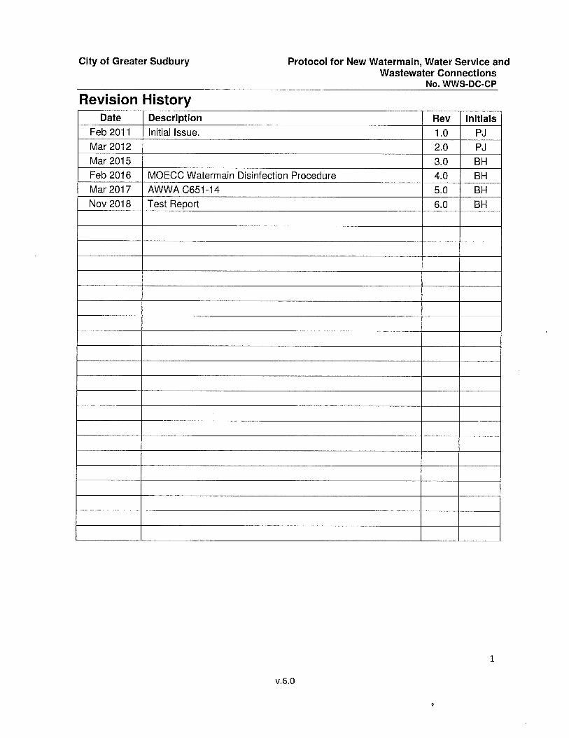
Revision HistoryDate Description Rev Initials
Feb 2011 Initial Issue. 1.0 PJMar 2012 2.0 PJMar 2015 3.0 BHFeb 2016 MOECC Watermain Disinfection Procedure 4.0 BHMar 2017 AWWA C651-14 5.0 BHNov 2018 Test Report 6.0 BH
1
v.6,0

City of Greater Sudbury
PURPOSE
Protocol for New Watermain, Water Service andWastewater Connections
No. WWS-DC-CP
The following information is provided as a protocol to be followed when a new watermain, water service or wastewater connection is required for all projects, including CGS capital projects. The only exception for CGS capital projects is that the permits and fees may not need to be obtained or purchased, however the timeframes and methods for requesting inspection and connection still apply.
GENERAL INFORMATION
All water and wastewater connections and service installations must conform to the latest revisions of the Ontario Provincial Standard Drawings (OPSD) and Ontario Provinciai Standards and Specifications (OPSS) as amended by the City of Greater Sudbury (GSSD and GSSS). All watermain work must comply with American Water Works Association (AWWA) Standard C651- 14 as well as the Ministry of the Environment and Climate Change (MOECC) Watermain Disinfection Procedure.
Any valve manipulation (including service boxes) and live taps on existing mains, in accordance with the Safe Drinking Water Act 2002, must be performed by licensed Operators (City D&C Operators) only. If it is proven that operational functions, such as hydrant operation, valve manipulation or live taps have been performed by an unauthorized person, that person and their employer will be reported to the Ministry of the Environment, Conservation and Parks, in accordance with due diligence requirements for licensed operators. Any violation of the above will also be noted during the City’s project evaluation procedure and included in our contractor prequalification review files. In addition, live taps (completed by licensed operators/City forces) will only be permitted if a valve is located at the property line, to isolate the system.
Vertical and horizontal separations will follow MECP Procedure F-6-1, Procedures to Govern Separation of Sewers and Watermains, and has been included in Appendix A. Minimum cover requirements for watermains, sewers, and services are set out in the City of Greater Sudbury Standard Drawings and Standard Specifications, and have been included in Appendix B. If connections to existing infrastructure cannot meet the above guideiines alternate methods may be used but must first be approved by CGS staff. Contact the Distribution and Collection Operations Engineer for approval of any non-standard sewer or water construction if connecting to existing infrastructure. In the case of a new subdivision the above standards must be met.
To allow a new connection, the City must be satisfied that the system has been installed as per the approved plans. All systems must be in place and all connections must be ready to connect. If City forces are called to site and the system is not installed in general conformance with the design and/or does not meet the appropriate drinking water regulations for connection, connections will be denied and the owner will be charged for the additional time required for the Construction Services Inspector and/or Operator in Charge (OIC) to return to site. All connection decisions will be at the discretion of the Overall Responsible Operator (ORO), regardless of what testing has commenced or been completed on the newly installed systems.
The City of Greater Sudbury urges the Permit Applicant / Contractor / Property Owners / Property Developers / Consultant (herein referred to as the "Applicant”) to comply with all Occupational Health and Safety legislation, requiring workers to wear personal protective
2
v.6.0

City of Greater Sudbury
equipment at all times, including but not limited to reflective safety vests, hardhats, eye protection, and approved safety footwear. All contractors and consultants working within the CGS Right of Way (ROW) are required to have the appropriate NORCAT modules as directed by a CGS representative and must be able to provide proof of training to City forces on request by carrying NORCAT issued photo ID and training credentials. City forces have been instructed by their supervisors to not enter any trench that does not meet proper trench standards; the Applicant is therefore advised to ensure proper trenching so as not to impede work and incur additional fees to have City forces return when it is safe to work.
If service interruptions are required to complete a new connection the Applicant is required to provide notice to all affected residents and businesses at least 24 hours in advance of the interruption. If the service interruption is going to affect any sensitive receptors a longer period of notice may be helpful to accommodate their needs. Service interruption notices must first be provided to the Distribution and Collection Operations Engineer or designate for preapproval prior to being distributed to the public. The Distribution and Collection Operations Engineer or designate requires at least two (2) working days to review the service interruption notice.
Before any watermain, wastewater or water service inspection or connection can be requested, the applicant must ensure that he/she has obtained or purchased the following from the Engineering Services Engineering Review Technician, as required;
1. Construction Services Inspection Fee2. Tapping Fee3. Connection Permit4. Road Occupancy Permit5. Restoration Work Order and Deposit6. OIC Deposit
The Engineering Review Technician will then inform the Manager of Construction Services/Construction Services Coordinator and the Linear Infrastructure Services Supervisor of Distribution and Collection that they can proceed with the inspection and connection. The Applicant will not contact Construction Services or Linear infrastructure Services directly to request an inspection or connection until the above have been obtained or paid. Once the above have been obtained or paid. Linear Infrastructure Services and Construction Services require 48 hours notice for any inspection services/connection requests.
Notice to Linear Infrastructure Services is not considered received until verbal confirmation has been given by the appropriate Supervisor II of Distribution and Collection; the Supervisor II of Distribution and Collection is to be contacted by telephone. Notice to Construction Services is not considered received until verbal confirmation has been given by the Manager of Construction Services/Construction Services Coordinator; the Construction Services/Construction Services Coordinator is to be contacted by telephone.
ROLE OF THE OIC fOperator-in-Charae)
An OIC must be present for all connections to the City’s water distribution system. The OIC is only there to witness the connection and ensure appropriate measures are taken to prevent contamination to the existing drinking water system. The OIC will only advise on whether the new system has been adequately disinfected at the connection site and meets all appropriate
Protocol for New Watermain, Water Service andWastewater Connections
No. WWS-DC-CP
3
v.6.0
City of Greater Sudbury
drinking water regulations. It is not the OIC’s responsibility to inspect the new distribution system assets nor to advise on the distribution system design and construction. All questions regarding design and construction including thrust blocks, Denso products, and compaction should be directed to Construction Services or the appropriate contact in Development Services. A final inspection of the new system by Linear Infrastructure Services will still be required after connection to verify that the system has no deficiencies.
Protocol for New Watermain, Water Service andWastewater Connections
No. WWS-DC-CP
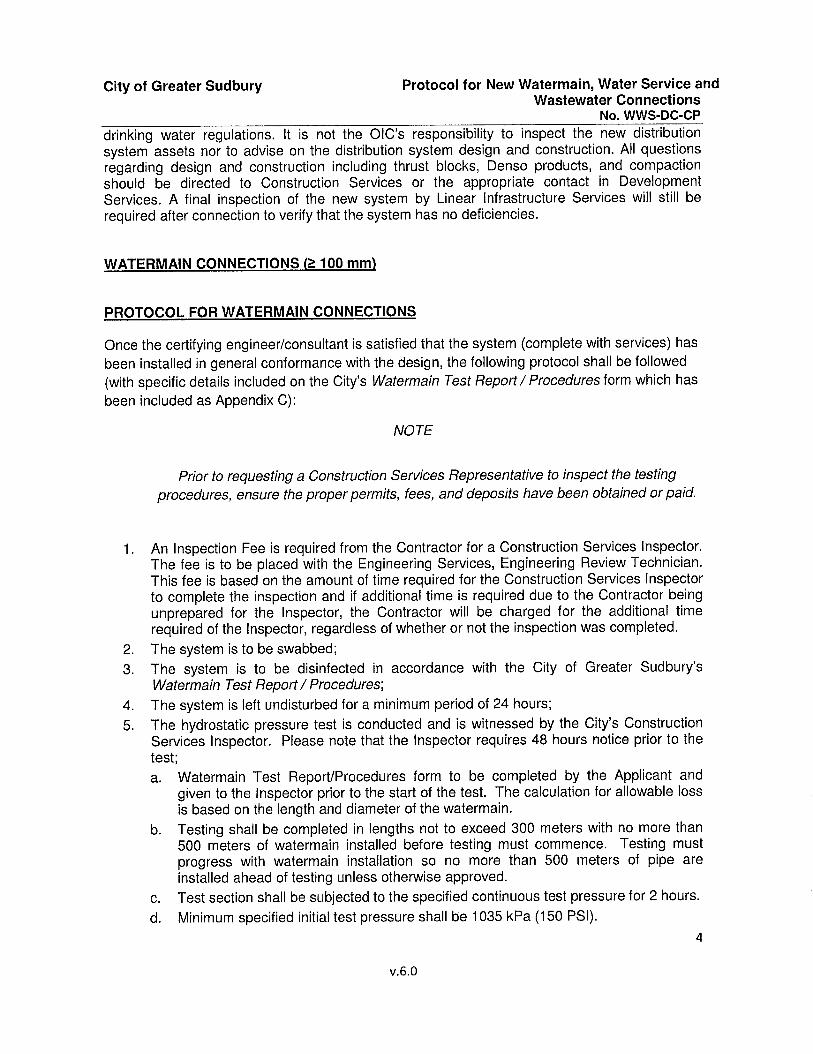
WATERMAIN CONNECTIONS l> 100 mm)
PROTOCOL FOR WATERMAIN CONNECTIONS
Once the certifying engineer/consultant is satisfied that the system (complete with services) has been installed in general conformance with the design, the following protocol shall be followed (with specific details included on the City’s Watermain Test Report / Procedures form which has been included as Appendix C):
NOTE
Prior to requesting a Construction Services Representative to inspect the testing procedures, ensure the proper permits, fees, and deposits have been obtained or paid.
1. An Inspection Fee is required from the Contractor for a Construction Services Inspector. The fee is to be placed with the Engineering Services, Engineering Review Technician. This fee is based on the amount of time required for the Construction Services Inspector to complete the inspection and if additional time is required due to the Contractor being unprepared for the Inspector, the Contractor will be charged for the additional time required of the Inspector, regardless of whether or not the inspection was completed.
2. The system is to be swabbed;3. The system is to be disinfected in accordance with the City of Greater Sudbury’s
Watermain Test Report/Procedures',4. The system is left undisturbed for a minimum period of 24 hours;5. The hydrostatic pressure test is conducted and is witnessed by the City’s Construction
Services Inspector. Please note that the Inspector requires 48 hours notice prior to the test;a. Watermain Test Report/Procedures form to be completed by the Applicant and
given to the Inspector prior to the start of the test. The calculation for allowable loss is based on the length and diameter of the watermain.
b. Testing shall be completed in lengths not to exceed 300 meters with no more than 500 meters of watermain installed before testing must commence. Testing must progress with watermain installation so no more than 500 meters of pipe are installed ahead of testing unless otherwise approved.
c. Test section shall be subjected to the specified continuous test pressure for 2 hours.d. Minimum specified initiai test pressure shall be 1035 kPa (150 PSI).
4
v.6.0
City of Greater Sudbury
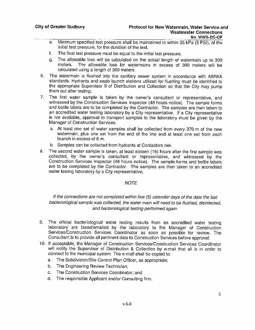
e. Minimum specified test pressure shaii be maintained to within 35 kPa (5 PSi), of the initiai test pressure, for the duration of the test.
f. The finai test pressure must be equal to the initial test pressure.g. The allowable loss will be calculated on the actual length of watermain up to 300
meters. The allowable loss for watermains in excess of 300 meters will be calculated using a length of 300 meters.
6. The watermain is flushed into the sanitary sewer system in accordance with AWWA standards. Hydrants and swab launch stations utilized for flushing must be identified to the appropriate Supervisor II of Distribution and Collection so that the City may pump them out after testing.
7. The first water sample is taken by the owner's consultant or representative, and witnessed by the Construction Services Inspector (48 hours notice). The sample forms and bottle labels are to be completed by the Contractor. The samples are then taken to an accredited water testing laboratory by a City representative. If a City representative is not available, approval to transport samples to the laboratory must be given by the Manager of Construction Services.a. At least one set of water samples shall be collected from every 370 m of the new
watermain, plus one set from the end of the line and at least one set from each branch in excess of 6 m.
b. Samples can be collected from hydrants at Contactors risk.8. The second water sample is taken, at least sixteen (16) hours after the first sample was
collected, by the owner’s consultant or representative, and witnessed by the Construction Services Inspector (48 hours notice). The sample forms and bottle labels are to be completed by the Contractor. The samples are then taken to an accredited water testing laboratory by a City representative;
NOTE
Protocol for New Watermain, Water Service andWastewater Connections
No. WWS-DC-CP
If the connections are not completed within five (5) calendar days of the date the last bacteriological sample was collected, the water main will need to be flushed, disinfected,
and bacteriological testing performed again.
9. The official bacteriological water testing results from an accredited water testing laboratory are faxed/emailed by the laboratory to the Manager of Construction Services/Construction Services Coordinator as soon as possible for review. The Consultant is to provide all pertinent data to Construction Services before approval.
10. If acceptable, the Manager of Construction Services/Construction Services Coordinator will notify the Supervisor of Distribution & Collection by e-mail that all is in order to connect to the municipal system. The e-mail shall be copied to:a. The Subdivision/Site Control Plan Officer, as appropriate;b. The Engineering Review Technician;c. The Construction Services Coordinator; andd. The responsible Applicant and/or Consulting firm.
5
v.6.0
City of Greater Sudbury
Unless the work is associated with a Capital Project, please note that the Consultantmust send the entire certification package to the Subdivision/Site Control Plan Officer at Development Approvals, including preliminary as-built drawings;
11. A deposit is required from the Contractor for the OIC service. The deposit is to be placed with the Engineering Services, Engineering Review Technician. This deposit is based on the amount of time required for the OIC to witness the connection. If the Contractor is unprepared for the OIC the Contractor will be charged for the additional time required of the Operator, regardless of whether or not the connections are completed.
12. On the day of the connection:a. The Contractor supplies all equipment, labour and materials including the chlorine;
Please note that chlorine must be ANSI / AWWA approved for contact with potable water;
b. The OIC for Distribution & Collection shali be on-site to oversee and advise as directed by the ORO for Distribution & Collection;
0. The Construction Services Inspector or Consultant is to be on-site for tie-in documentation;
d. The Consultant is to be on-site^ and is responsible for providing all preliminary as- constructed information to the city;
e. The Contractor must disinfect all pipe work, fittings and the trench base (the area in the vicinity of the pipe work) with a 1% hypochlorite solution; and
f. It will be at the ORO’s discretion to have the OIC complete a slug chlorination process on the connecting pipe and the existing isolated water main, by which the OIC will slowly fill the main and begin flushing it. Thereafter, it will be thoroughly flushed and checked by the OIC until it matches the residual concentration of the water in the local distribution system.
13. City forces ensure that the wastewater system is prepared to accept flow;14. Once the above criteria are satisfied the connection is approved.15. The appropriate valve/valves are opened by the OIC and the system is pressurized only
once at least 1 m of compacted soils are placed over the connection site.
Protocol for New Watermain, Water Service andWastewater Connections No. WWS-DC-CP
WATER SERVICE CONNECTIONS (<100 mml
PROTOCOL FOR WATER SERVICE CONNECTIONS
New water service connections are inspected by the OIC from the lot line to the foundation. The Construction Services Inspector inspects from the lot line to the main. Once the certifying engineer/consultant is satisfied that the water service has been installed in general conformance with the design, the following protocol must be followed:
' If Consultant is not on-site, the OIC will leave the site and charges for their time will be applied.6
City of Greater Sudbury
1. The Applicant or the Applicants Contractor supplies all equipment, labour and materials Including the chlorine; Please note that chlorine must be ANSI / AWWA approved for contact with potable water;
2. The OIC is to be onsite to oversee and advise as directed by the ORO;3. The Contractor must disinfect all pipe work, fittings, and the trench base (the area in the
vicinity of the pipe work) with a 1% hypochlorite solution;4. The Construction Services Inspector will inspect the pressure side pipe material. Joints,
depth of cover, curbstop, service box, and corrosion protection;5. The OIC will perform pressure test on new service;6. The OIC will ensure that the wastewater system Is prepared to accept flow;7. Once the above criteria are satisfied the connection is deemed completed and approved.8. The appropriate valve/valves are opened by the OIC and the system is pressurized only
once at least 1 m of compacted soils are placed over the connection site.
Protocol for New Watermain, Water Service andWastewater Connections
No. WWS-DC-CP
WASTEWATER CONNECTIONS
PROTOCOL FOR WASTEWATER CONNECTIONS
New wastewater connections are inspected by the OIC from the lot line to the foundation. The Construction Services Inspector inspects from the lot line to the main. Once the certifying engineer/consultant is satisfied that the wastewater system/service has been installed in general conformance with the design, this protocol must be followed:
1. The OIC Is to be onsite to oversee and advise as directed by the ORO;2. The Construction Services Inspector will inspect wastewater pipe material, grade,
alignment, bends, joints, and manholes as required;3. The OIC will perform a falling head test with no ailowable decrease and inspect the Joints
for leakage;4. The test plug is removed from the test fitting at lot line and the water draining is
monitored to ensure it completely drains and no backwash occurs; and,5. Once the above criteria are satisfied the system is Approved by the OIC.
PROTOCOL FOR DISCONNECTIONS
Water and wastewater services that are to be abandoned in favor of a new connection must be disconnected before the new connection can be made.
Disconnections of existing unused water services are to be performed by the Applicant, and witnessed by City forces prior to backfilling. Domestic water services require the existing mainstop to be turned off at the main, the service line cut out at the mainstop, and the removal or abandonment of the existing curbstop. The existing service line is not to be removed. Larger water services that utilize a “T” connection are to have the “T” cut out of the existing main during a time of watermain shutdown, and removal of the existing property line curbstop. Curbstops that are removed are to be backfilled and the excavated area must be completely restored. Valve chambers to be removed are to have the chamber broken down to 1.0 m below final
7
v.6.0

City of Greater Sudbury Protocol for New Watermain, Water Service andWastewater Connections
No. WWS-DC-CPgrade, backfilled with granular material, drain holes made in the bottom of the structure, and theexcavated area must be completely restored.
Disconnections of existing unused wastewater services are to be performed by the Applicant, and witnessed by City forces prior to backfilling. Wastewater service laterals require the existing lateral to be cut and capped directly at the main. Existing manholes to be removed are to be broken down to 1.0 m below final grade, backfilled with granular material, drain holes made in the bottom of the structure, and the excavated area must be completely restored.
Repair/reinstatement of watermains or wastewater mains that were part of the disconnection is to be completed following City standards.
If the removal of connections at the main will cause additional damage to the CGS ROW, special approval may be given to disconnect at an alternate location by the Distribution and Collection Operations Engineer.
8
v.6.0
APPENDIX A:
Procedure F-6-1
PROCEDURE F-6-1 (formerly referenced by 08-02)
Procedures to Govern Separation of Sewers and Watermains
PROCEDURE F-6-1PROCEDURES TO GOVERN THE SEPARATION
OF SEWERS AND WATERMAINS
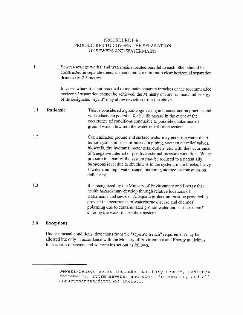
Sewers/sewage works’ and watermains located parallel to each other should be constructed in separate trenches maintaining a minimum clear horizontal separation distance of 2.5 metres.
In cases where it is not practical to maintain separate trenches or the recommended horizontal separation cannot be achieved, the Ministry of Environment and Energy or its designated "agent" may allow deviation from the above.
Rationale This is considered a good engineering and construction practice andwill reduce the potential for health hazard in the event of the occurrence of conditions conducive to possible contaminated ground water flow into the water distribution system.
Contaminated ground and surface water may enter the water distribution system at lealcs or breaks in piping, vacuum ah relief valves, blowoffs, fire hydrants, meter sets, outlets, etc. with the occuiTence of a negative internal or positive external pressure condition. Water pressure in a part of the system may be reduced to a potentially hazardous level due to shutdowns in the system, main breaks, heavy fire demand, high water usage, pumping, storage, or transmission deficiency.
It is recognized by the Ministry of Environment and Energy that health hazards may develop through relative locations of wateimains and sewers. Adequate protection must be provided to prevent the occumence of waterborne disease and chemical poisoning due to contaminated ground water and surface runoff entering the water distribution system.
Exceptions
Under unusual conditions, deviations fi'om the "separate trench" requirement may be allowed but only in accordance with the Ministry of Envhonment and Energy guidelines for location of sewers and watermains set out as follows.
1 Sewers/Sewage works includes sanitary sewers, sanitary forcemains, storm sewers, and storm forcemains, and all appurtenances/fittings thereto.
3.0 General
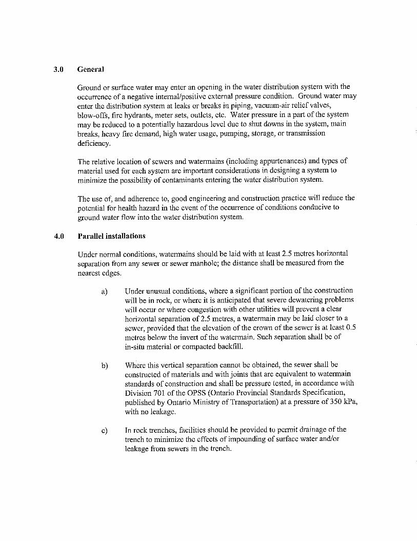
Ground or surface water may enter an opening in the water distribution system with the occurrence of a negative intemal/positive external pressure condition. Ground water may enter the distribution system at leaks or breaks in piping, vacuum-air relief valves, blow-offs, fire hydrants, meter sets, outlets, etc. Water pressure in a part of the system may be reduced to a potentially hazardous level due to shut downs in the system, main breaks, heavy fire demand, high water usage, pumping, storage, or transmission deficiency.
The relative location of sewers and watermains (including appurtenances) and types of material used for each system are important considerations in designing a system to minimize the possibility of contaminants entering the water distribution system.
The use of, and adherence to, good engineering and construction practice will reduce the potential for health hazard in the event of the occurrence of conditions conducive to ground water flow into the water distribution system.
4.0 Parallel installations
Under normal conditions, watermains should be laid with at least 2.5 metres horizontal separation from any sewer or sewer manhole; the distance shall be measured from the nearest edges.
a) Under unusual conditions, where a significant portion of the construction will be in rock, or where it is anticipated that severe dewatering problems will occur or where congestion with other utilities will prevent a clear horizontal separation of 2.5 metres, a watermain may be laid closer to a sewer, provided that the elevation of the crown of the sewer is at least 0.5 metres below the invert of the watermain. Such separation shall be of in-situ material or compacted backfill.
b) Where this vertical separation cannot be obtained, the sewer shall be constructed of materials and with joints that are equivalent to watermain standards of construction and shall be pressure tested, in accordance with Division 701 of the OPSS (Ontario Provincial Standards Specification, published by Ontario Ministry of Transportation) at a pressure of 350 kPa, with no leakage.
c) In rock ti-enches, facilities should be provided to peimit drainage of the trench to minimize the effects of impounding of surface water and/or leakage from sewers in the trench.

5.0 Crossings
5.1 Under normal conditions, watermains shall cross above sewers with sufficient vertical separation to allow for proper bedding and structural support of the watermain and sewer main.
5.2 When it is not possible for the watermain to cross above the sewer, the watermain passing under a sewer shall be protected by providing:a) A vertical separation of at least 0.5 metres between the invert of the sewer
and the crown of the watennain.b) Adequate structural support for the sewers to prevent excessive deflection
of joints and settling.c) That the length of water pipe shall be centred at the point of crossing so
that the joints will be equidistant and as far as possible from the sewer.
6.0 SERVICE CONNECTIONSWlierever possible, the construction practices outlined in this guideline should apply with respect to sewer and water services.
7.0 TUNNEL CONSTRUCTIONIf the "Tunnel" is of sufficient size to peimit a man to enter the tunnel for the purposes of maintenance, etc., it is pennissible to place the sewer and watermain through the tunnel providing the watermain is hung above the sewer.If the tunnel is sized only to carry the pipes, or if the tunnel is subject to flooding, the sewer shall be constructed of materials and with joints that are equivalent to watermain standards of construction and shall be pressure tested, in accordance with Division 701 of the OPSS at a pressure of 350 IcPa with no leakage.
8.0 DESIGN FACTORSWhen local conditions do not pennit the desired spacing, or water and sewer lines or other conditions indicate that detailed investigations are warranted, the following factors should be considered in the design of the environment and relative location of water and sewer lines.
This list of factors should be considered as a guide. The list is not all-inclusive.a) Materials, types of joints and identification for water and sewage pipes;b) Soil conditions, e.g. in-situ soil and backfilling materials and compaction
techniques;c) Service and branch connections into the watermain and sewer lines;d) Compensating variations in the horizontal and vertical separations;e) Space for repair and alterations of water and sewer pipes;f) Offsetting of pipes around manholes;g) Location of ground-water table and fench drainage techniques;h) Other sanitary facilities such as septic tanlcs and tile fields, etc.

VALVE, AIR RELIEF, METER AND BLOW-OFF CHAMBERS
a) Chambers or pits containing valves, blow- offs, meters or other such appurtenances to a water distribution system shall not be connected directly to any sanitary sewer, but may be connected to storm sewers provided that some means of back flow prevention is included.
b) Blow-offs or air relief valves shall not be connected directly to any sewer.c) Such chambers or pits shall be drained to the surface of the ground where
they are not subject to flooding by surface water; to absorption pits underground or to a sump within the chamber where ground water level is above the chamber floor.
POTABLE WATER RESERVOIRS BELOW NORMAL GROUND SURFACE AND WELL SUPPLIES
Sewers, drains, and similar sources of contamination should be kept at least 15 m from potable water reservoirs below normal ground surface and well supplies. Mechanical-jointed water pipes, pressure tested, in accordance with Division 701 of the OPSS at a pressure of 350 kPa with no leakage, may be used for gravity sewers at lesser separations.
UNACCEPTABLE INSTALLATIONS
No watermain or service line shall pass through or come into contact with any part of a sewer, sewer manhole and/or septic tank and tile field or similar sources of contamination.

APPENDIX B:
City of Greater Sudbury Standard Drawings & Specifications
FtNiSHED GRADE-
LONG RADIUS BEND AS REQUIRED
BACKFILL AS SPECIFIED50x100x300 LONG WOOD CROSS TEE, 300 mm ABOVE TOP OF PIPE
50x100 TIMBER STAKE TO INVERT. PAINT FLUORESCENT GREEN
t ________ —
_________
— 100 MINCROWLE TEST FITTING J
STREET LINE
BEDDING AS PER GSSD-1227.010 BACKFILL AS SPECIFIED
LONG RADIUS BEND AS REQUIRED
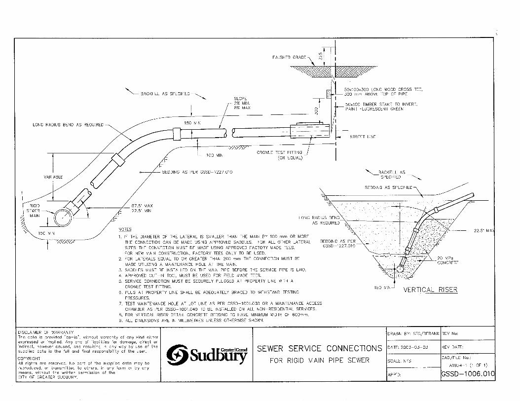
XVXV/-IF THE DIAMETER OF THE LATERAL IS SMALLER THAN THE MAIN BY 100 mm OR MORE THE CONNECTION CAN BE MADE USING APPROVED SADDLES. FOR ALL OTHER LATERAL SIZES THE CONNECTION MUST BE MADE USING APPROVED FACTORY MADE TEES.FOR NEW MAIN CONSTRUCTION, FACTORY TEES ONLY TO BE USED.
2. FOR LATERALS EQUAL TO OR GREATER THAN 200 mm THE CONNECTION MUST BE MADE UTILIZING A MAINTENANCE HOLE AT THE MAIN.
3. SADDLES MUST BE INSTALLED ON THE MAIN PIPE BEFORE THE SERVICE PIPE IS LAID.4. APPROVED CUT-IN TOOL MUST BE USED FOR FIELD MADE TEES.5. SERVICE CONNECTION MUST BE SECURELY PLUGGED AT PROPERTY LINE WITH A
CROWLE TEST FITTING.6. PLUG AT PROPERTY LINE SHALL BE ADEQUATELY BRACED TO WITHSTAND TESTING
PRESSURES.7. TEST MAINTENANCE HOLE AT LOT LINE AS PER GSSD-1001.030 OR A MAINTENANCE ACCESS
CHAMBER AS PER GSSD-1001.040 TO BE INSTALLED ON ALL NON-RESiDENTIAL SERVICES.8. FOR VERTICAL RISER DETAIL CONCRETE BEDDING TO HAVE MINIMUM WIDTH OF 600mm.9. ALL DIMENSIONS ARE IN MILLIMETRES UNLESS OTHERWISE SHOWN.
22.5' MA>
BEDDING AS PER GSSD-1227.010
150MIN-J VERTICAL RISER
DISCLAIMER OF WARRANTYThe data is provided ”as-is”, without warranty of any kind either expressed or implied. Any and all liabilities for damage, direct or indirect, however caused, and resulting in any woy by use of the supplied data is the full and final responsibility of the user.
COPYRIGHTAll rights are reserved. No part of the supplied data may be reproduced, or transmitted to others, in any form or by any means, without the written permission of the CITY OF GREATER SUDBURY.
©Sudffify SEWER SERVICE CONNECTIONSFOR RIGID MAIN PIPE SEWER
DRAWN BY: STS/RFRANK
DATE: 2003-03-03
SCALE; NTS
APP D:
REV DATE:
CAD/FILE No.:
A1954-1 (1 OF 1)
GSSD-1006.010

NOTES
1. IF THE DIAMETER OF THE LATERAL IS SMALLER THAN THE MAIN BY IQO mm OR MORE THE CONNECTION CAN BE MADE USING APPROVED SADDLES. FOR ALL OTHER LATERAL SIZES THE CONNECTION MUST BE MADE USING APPROVED FACTORY MADE TEES.FOR NEW MAIN CONSTRUCTION, FACTORY TEES ONLY TO BE USED.
2. FOR LATERALS EQUAL TO OR GREATER THAN 200 mm THE CONNECTION MUST BE MADE UTILIZING A MAINTENANCE HOLE AT THE MAIN.
3. SADDLES MUST BE INSTALLED ON THE MAIN PIPE BEFORE THE SERVICE PIPE IS LAID.
4. APPROVED CUT-IN TOOL MUST BE USED FOR FIELD MADE TEES.5. SERVICE CONNECTION MUST BE SECURELY PLUGGED AT PROPERTY LINE
WITH A CROWLE TEST FITTING.6. PLUG AT PROPERTY LINE SHALL BE ADEQUATELY BRACED TO WITHSTAND
TESTING PRESSURES.7. ALL DIMENSIONS ARE IN MILLIMETRES UNLESS OTHERWISE SHOWN.8. MAINTENANOE HOLE AT LOT LINE AS PER GSSD-1001.030 TO BE INSTALLED
ON ALL NON-RESIDENTIAL SERVIOES.
DRAWN BY: STS/RFRANK REV No:
SEWER SERVICE CONNECTIONS DATE: 2003-03-03 REV DATE:
oticijjury FOR FLEXIBLE MAIN PIPE SEWER SCALE: NTSCAD/FILE No.:
AI955-1 (1 OF 1)
APP'D: GSSD-1006.02CDISCLAIMER OF WARRANTY : The data is provided ”as—is", without worronty of any kind either expressed or implied. Any and all liabilities fordamage, direct or indirect, however caused, and resulting in any way by use of the supplied data is the full and final responsibility of the user.
COPYRIGHT : All rights are reserved. No part of the supplied data may be reproduced, or transmitted to others,in any form or by any means, without the prior written permission of the CITY OF GREATER SUDBURY.
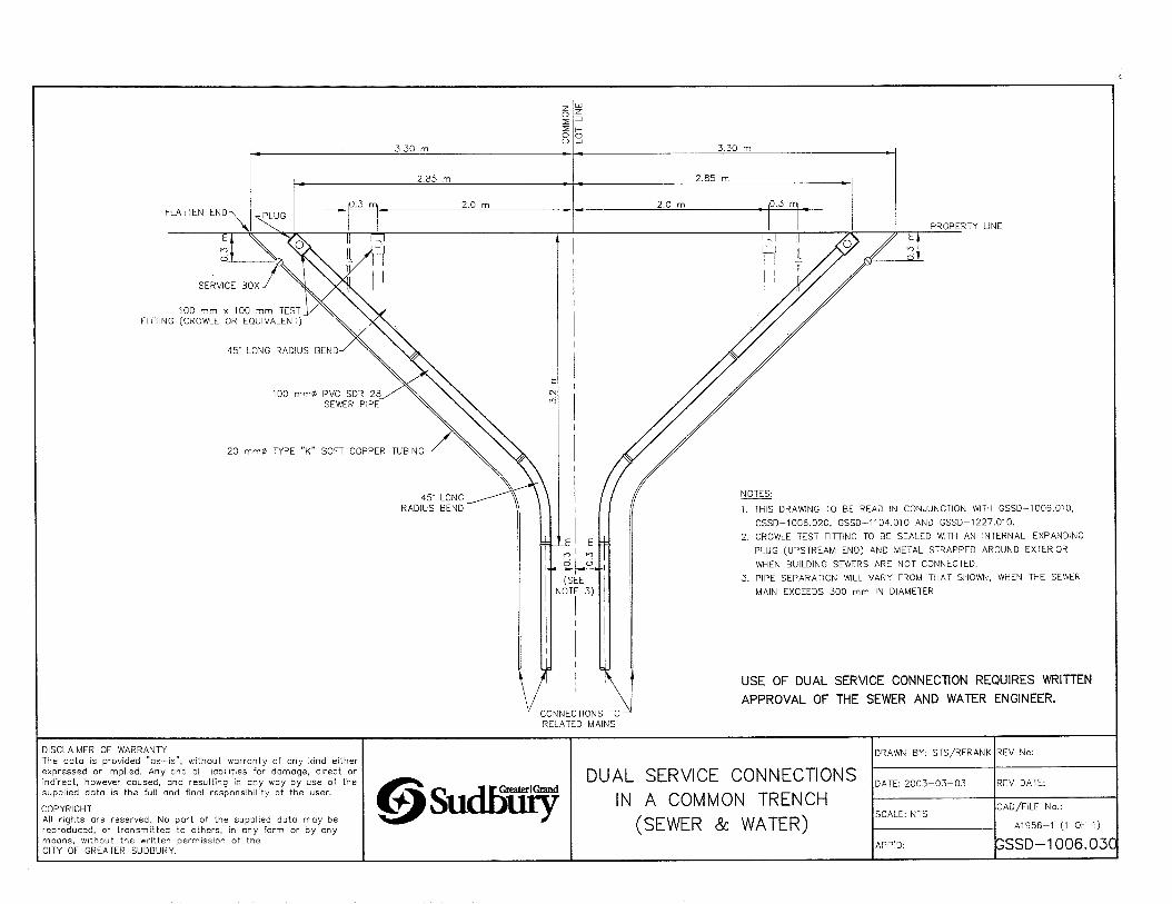
100 mm X 100 mm TEST FITTING (CROWLE OR EQUIVALENT)
PROPERTY LINE
20 mm0 TYPE ”K" SOFT COPPER TUBING
1. THIS DRAWING TO BE READ IN CONJUNCTION WITH GSSD-1006.010, GSSD-1006.020, GSSD-1104.010 AND GSSD-1 227.010.
2. CROWLE TEST FITTING TO BE SEALED WITH AN INTERNAL-EXPANDING PLUG (UPSTREAM END) AND METAL STRAPPED AROUND EXTERIOR
WHEN BUILDING SEWERS ARE NOT CONNECTED.3. PIPE SEPARATION WILL VARY FROM THAT SHOWN, WHEN THE SEWER
MAIN EXCEEDS 300 mm IN DIAMETER.
USE OF DUAL SERVICE CONNECTION REQUIRES WRITTEN APPROVAL OF THE SEWER AND WATER ENGINEER.
■CONNECTIONS TO- RELATED MAINS
DISCLAIMER OF WARRANTYThe data is provided ”qs—is”, without warranty of any kind either expressed or implied. Any and all liabilities for damage, direct or indirect, however caused, and resulting in any way by use of the supplied data is the full and final responsibility of the user.
COPYRIGHTAll rights are reserved. No part of the supplied data may be reproduced, or transmitted to others, in any form or by any means, without the written permission of the CITY OF GREATER SUDBURY.
f f Greater I GrandSudbiiyDUAL SERVICE CONNECTIONS
IN A COMMON TRENCH (SEWER & WATER)
DRAWN BY: STS/RFRANK
DATE: 2003-03-03
SCALE: NTS
APP’D;
REV No:
REV DATE:
CAD/FILE No.:
A1956-1 (1 OF 1)
|GSSD-1006.03q

FINISHED GRADE
STD COVER (SEE NOTE 2)
VARIES-(SEE NOTE 8)
130mm ID
UPPER RISER-
140mm DIA Cl RISER PIPE ■
LOWER RISER-
100mm DIA _ PVC RISER PIPE
45- SWEEP BEND
yAy?>yA-x
■ 110mm OD
100mm DIA PVC PIPE @ MIN 2% GRADE
(FROM HOUSE)
NOTES: ^
1. UPPER AND LOWER ASSEMBLIES TO BE ADEQUATELY BRACED WHILE BACKFILLING, AND MUST REMAIN PLUMB.
2. CLEANOUT COVER SHALL BE OF STD. IRON FOR EASEOF LOCATING WITH DIP NEEDLE (SEE STD. GSSD-1101.020).
3. DEPTH OF WYE MUST BE ADEQUATE TO PERMIT CONNECTION TO OUTLET PIPE AND MAINTAIN THE MINIMUM GRADE OF 2%.
4. THIS STANDARD SHALL APPLY FOR SEWER CONNECTIONS WHEN THE LENGTH OF SERVICE EXCEEDS 30 METRES. LOCATION OF VERTICAL CLEANOUT SHALL BE AS SPECIFIED BY THE ENGINEER.
5. THIS STANDARD TO BE READ IN CONJUNCTION WITH CITY OF GREATER SUDBURY STANDARD DRAWINGS GSSD-1006.03Q AND GSSD-1227.010.
6. ALL PVC PIPE SHALL BE S.O.R. 28.
7. BACKFILL MATERIAL SHALL CONSIST OF COMPACTED SAND BEDDING IN 300 mm LAYERS.
8. COVER SHALL BE 100mm BELOW FINISHED GRADEIN SODDED OR GRAVEL AREAS. COVER SHALL BE FLUSH WITH FINISHED GRADE IF IN ASHPALT OR CONCRETE.
10Ommx! OOmmxl 00mm WYE CONNECTION (ALL BELL ENDS)
100mm DIA PVC PIPE @ MIN 2% GRADE (TO SEWERMAIN)
DRAWN BY: SAG REV No: 2
STANDARD VERTICAL CLEANOUT DATE: 2003-03-03 REV DATE: JAN/2013ou.mjury ON A SANITARY SEWER SERVICE SCALE: NTSCAD/FILE No.:
A1957-1 (1 OF 1)
GSSD-1025.010APP'D:
DISCLAIMER OF WARRANTY ; The data Is provided "es-ls”, without warranty of any kind either expressed or Implied. Any and all liabilities fordamage, direct or indirect, however caused, and resulting In any way by use of the supplied data Is the full and final responsibility of the user.
COPYRIGHT ; All rights are reserved. No part of the supplied data may be reproduced, or transmitted to others,in any form or by any means, without the prior written permission of the CITY OF GREATER SUDBURY.

DISTANCE VARIES
FLANGED JOINT & BLIND FLANGE CORROSION PROTECTION
SHALL BE PRIME AND MASTIC ONLYSTANDARD VALVE CHAMBER FRAME AND COVER. SEE (OPSD-402.010)
PRECAST CONC ADJUSTMENT RINGS MIN ONE ROW ■
TO 300mm MAX
L
CONC THRUST BLOCK POURED' “IN PLACE (SEE OPSD-1103.010 '
OR GSSD-1103.010)
SEE TABLE 1 FOR VALVE SIZE
PVC LEAD IS TO BE PLACED HORIZONTALLY WITH NO VERTICAL BENDS
BEDDING AS PER GSSD-1227.010
PRECAST CONC MAINTENANCE HOLE OPSD-701.030
(ALIGNMENT TO BE FIELD SET)
Dl CLASS 52 CEMENT LINED PIPE
PIPE RESTRAINER GLAND
BOTTOM RISER SECTION WITH OPENING TO SUIT
_WM___I .j
1
DISTANCE TO BE FIELD SET
THRUST BLOCK AS PERGSSD-1103.010 OROPSD-1103.010
CORROSION PROTECTION
NOTE:
1. A POLYETHYLENE BOND BREAKER IS TO BE USED BETWEEN ALL CONCRETE THRUST BLOCKS AND FITTINGS.
2. ALL METALLIC FITTINGS & VALVES SHALL HAVE CORROSION PROTECTION
3. FROST STRAP INSTALLATION, AS PER OPSD-701.100.
4. ADJUSTMENT UNITS TO BE SET IN 12 mm MORTAR MIX.
5. TRACER WIRE AS PER GSSD-1110.000
6. ALL DIMENSIONS ARE SHOWN IN MILLIMETRES UNLESS OTHERWISE INDICATED.
TABLE 1
WM SIZESIZE OF TEE, PIPING,
GATE VALVE AND FITTING
100 100
150 150
200 200
250 250
300 300
400 300
0Sudbu^VALVE AND SWAB
LAUNCHING STATION WATERMAIN SIZES
100 mm TO 400 mm
DRAWN BY: BWK/MHD
DATE: 2003-03-03
SCALE: NTS
APP’D: PETER CHIESA
REV No:
REV DATE: 2013-01-01
CAD/FILE No.:
A1964-1 (1 OF 1)
lGSSD-1100.030DISCLAIMER OF WARRANTY : The data Is provided ”as-is”, without warranty of any kind either expressed or implied. Any and all liabilities fordamage, direct or indirect, however caused, and resulting in any way by use of the supplied data is the full and final responsibility of the user.
COPYRIGHT : All rights ore reserved. No part of the supplied data may be reproduced, or tronsmitted to others.in any form or by any means, without the prior written permission of the CITY OF GREATER SUDBURY.___________________________
2D
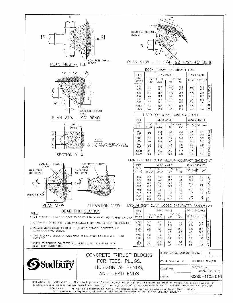
NOTE:D = INSIDE DIAMETER OF PIPE
OD = OUTSIDE DIAMETER OF PIPE
SECTION X-X
ROCK. GRAVEL, COMPACT SANDPIPE BEND ANGLE DEAD END/TEESIZE(mm)
W 1 11.25’
D T H 22.5* 45‘
Cm)90’
”B" (m) ”C" (m)
400 0.5 0.3 0.3 0.3 0.3 0.4 C/)450 0.3 0.3 0.3 0.3 0.3 0.5 o
in500 0,3 0.3 0.3 0.3 0.3 0.5 z:600 0.3 0.3 0.3 0.3 0.3 0.7 2750 0.3 0.3 0.3 0.3 0.4 o.a O
900 0.3 0.3 0.3 0.3 0.4 1.0 5
1050 0.3 0.3 0.4 0.3 0.5 1.11200 0.3 0.3 0.4 0.4 0.6 1.3 5
HARD DRY CLAY. COMPACT SANDPIPESIZE(mm)
BEND ANGLE DEAD END/TEE
W i 11.25’
D T H 22.5’ 45’
(m)90’
"B” (m) "C" (m)
400 0.3 0.3 0.3 0.3 0.4 0.4 CO
450 0.3 0.3 0.3 0.3 0.4 0.5 o
500 0.3 0.3 0.4 0.3 0.5 0.5 z
600 0.3 0.3 0.4 0.4 0,6 0.7 5
750 0.3 0.3 0.5 0.5 0.7 0.8CJ
900 0.3 0.3 0.6 0.6 0.8 1.0 5Z)
1050 0.3 0.4 0.7 0.7 1.0 1.1
1200 0.3 0.4 0.8 O.a 1.0 1.3 1
FIRM OR STIFF CLAY, MEDIUM COMPACT SAND/SILTCONCRETE THRUST PIPE BEND ANGLE DEAD END/TEE
SIZE(mm)
W 1 11.25'
D T H 22.5’
■‘A”45’
(m)90’
”B" (m) ”C" (m)
400 0.3 0.3 O.B 0.6 0.8 0.4 CO
450 0.3 0.3 0.7 0.6 0.9 0.5 o
500 0.3 0.4 0.7 0.7 0.9 0.5 z600 0.3 0.4 0.9 0.8 1.1 0.7 2750 0.3 0.6 1.1 1.0 1.4 0.8
Q
900 0.3 0.7 1.3 1.2 1.7 1.0 2Z)
1050 0.4 0.8 1.5 1.4 1.9 1.11200 0.4 0.9 1.^ 1.6 2.2 1.3 1
ELEVATION VIEW MEDIUM SOFT CLAY, LOOSE SATURATED SAND/CLAY
DEAD END SECTIONNOTES:
1. ALL CONCRETE THRUST BLOCKS TO BE POURED AGAINST UNDISTURBED GROUND.
2. CLEARANCE OF 80 mm TO BE MAINTAINED FROM FACE OF BELL TO CONCRETE.
3. POLYETHYLENE BOND BREAKER TO BE USED BETWEEN CONCRETE AND CORROSION PROCTECTION,
A. THIS BLOCKING DESIGN APPLIES ONLY WHERE 1100 kPa PRESSURE IS NOT EXCEEDED.
5. PRIOR TO POURING CONCRETE, ALL METALLIC FITTINGS SHALL HAVE CORROSION PROTECTION.
PIPE BEND ANGLE DEAD END/TEESIZE
(mm)W 1
11.25’D T H
22.5’ 45’(m)
90’”B" (m) "C" (m)
400 0.5 0.9 1.8 1.6 2.3 0.4 CO
450 0.5 1.0 2.0 1.8 2.6 0.5 o
500 0.6 1.1 2.2 2.0 2.8 0.5 z600 0,7 1.3 2.6 2.4 3.4 0.7 5750 0.8 1.6 3.2 3.0 4.2 0.8
o
900 1.0 2.0 3.8 3.6 5.0 1.0 2Z)
1050 1.1 2.2 4.4 4.1 5.8 1.1 >
1200 1.3 2.6 5.0 4.7 6.6 1.3 2
CONCRETE THRUST BLOCKSDRAWN BY: WJK/STS/RF REV No: 1
FOR TEES, PLUGS, DATE: 2003-03-03 REV DATE: MAY/08
HORIZONTAL BENDS,AND DEAD ENDS
SCALE: NTS
APP’D:
CAD/FILE No.:
A1966-1 (1 OF 1)
GSSD-1103.010DISCLAIMER OF WARRANTY : The data is provided ”as-is”, without vmrronty of any kind either expressed or implied. Any and oil liabilities fordamage, direct or indirect, however caused, and resulting in any way by use of the supplied data is the full and final responsibility of the user.
COPYRIGHT ; All rights are reserved. No part of the supplied data may be reproduced, or transmitted to others,in any form or by any meons, without the prior written permission of the CITY OF GREATER SUDBURY.
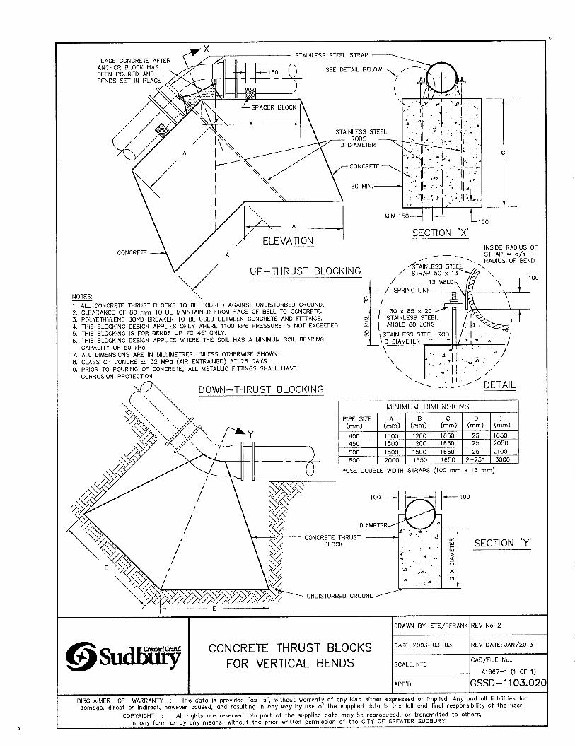
PLACE CONCRETE AFTER ANCHOR BLOCK HAS BEEN POURED AND BENDS SET IN PLACE
CONCRETE
NOTES:1. ALL CONCRETE THRUST BLOCKS TO BE POURED AGAINST UNDISTURBED GROUND.2. CLEARANCE OF 80 mm TO BE MAINTAINED FROM FACE OF BELL TO CONCRETE.3. POLYETHYLENE BOND BREAKER TO BE USED BETWEEN CONCRETE AND FITTINGS.4. THIS BLOCKING DESIGN APPLIES ONLY WHERE 1100 kPo PRESSURE IS NOT EXCEEDED.5. THIS BLOCKING IS FOR BENDS UP TO 45' ONLY.6. THIS BLOCKING DESIGN APPLIES WHERE THE SOIL HAS A MINIMUM SOIL BEARING
CAPACITY OF 50 kPo.7. ALL DIMENSIONS ARE IN MILLIMETRES UNLESS OTHERWISE SHOWN.8. CLASS OF CONCRETE: 32 MPa (AIR ENTRAINED) AT 28 DAYS.9. PRIOR TO POURING OF CONCRETE, ALL METALLIC FITTINGS SHALL HAVE
CORROSION PROTECTION
INSIDE RADIUS OF_____ ____ STRAP = o/s
^ RADIUS OF BEND^ Stainless steel \/ STRAP 50 X \
/ 13 WELD-X la \/ SPRING LINE
130 X 85 X 20 STAINLESS STEEL ANGLE 80 LONG
STAINLESS STEEL ROD
THRUST BLOCKING
\ D DIAMETER
A'
MINIMUM DIMENSIONSPIPE SIZE (mm)
A(mm)
B(mm)
C(mm)
D(mm)
E(mm)
400 1300 1200 1650 25 1650450 1500 1200 1650 25 2050
500 1500 1500 1650 25 2100
600 2000 1650 1650 2-25* 3000
‘USE DOUBLE WIDTH STRAPS (100 mm x 13 mm)
DIA1
CONCRETE THRUST BLOCK
UNDISTURBED GROUND
SECTION ’Y’
@Sudbuj^ CONCRETE THRUST BLOCKS FOR VERTICAL BENDS
DRAWN BY: STS/RFRANK
DATE: 2003-03-03
SCALE: NTS
APPD:
REV No: 2
REV DATE: JAN/2013
CAD/FILE No.:
A1967-1 (1 OF 1)
lGSSD-1103.020DISCLAIMER OF WARRANTY : The data is provided "as-is”, without warranty of any kind either expressed or implied. Any and all liabilities fordamage, direct or indirect, however caused, and resulting In any way by use of the supplied data is the full and final responsibility of the user.
COPYRIGHT : All rights are reserved. No part of the supplied data may be reproduced, or transmitted to others,in any form or by any means, without the prior written permission of the CITY OF GREATER SUDBURY.
3<m
< CD orSiSSee^ ro <D
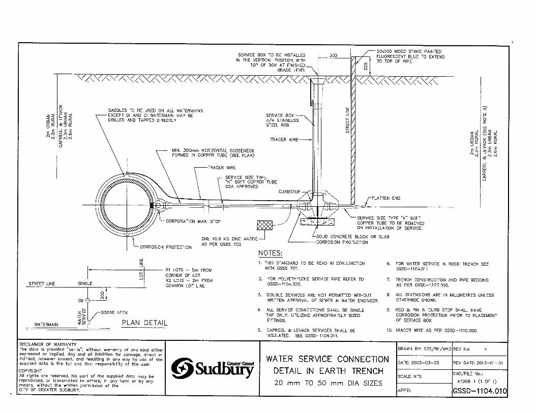
1. THIS STANDARD TO BE READ IN CONJUNCTION WITH GSSS 701.
2. FOR POLYETHYLENE SERVICE PIPE REFER TO GSSD-1104.020.
3. DOUBLE SERVICES ARE NOT PERMITTED WITHOUT WRITTEN APPROVAL OF SEWER & WATER ENGINEER.
4. ALL SERVICE CONNECTIONS SHALL BE SINGLE TAP ONLY. UTILIZING APPROPRIATELY SIZED FITTINGS.
5. CAPREOL & LEVACK SERVICES SHALL BE INSULATED. SEE GSSD-1104.011.
6. FOR WATER SERVICE IN ROCK TRENCH SEE GSSD-1104.011
7. TRENCH CONSTRUCTION AND PIPE BEDDING AS PER GSSD-1227.010.
8. ALL DIMENSIONS ARE IN MILLIMETRES UNLESS OTHERWISE SHOWN.
9. ROD & PIN IN CURB STOP SHALL HAVE CORROSION PROTECTION PRIOR TO PLACEMENT OF SERVICE BOX
10. TRACER WIRE AS PER GSSD-1110.000
DISCLAIMER OF WARRANTYThe data is provided "as—is", without warranty of any kind either expressed or implied. Any and all liabilities for damage, direct or indirect, however coused, and resulting in any way by use of the supplied data is the full and final responsibility of the user.
COPYRIGHTAll rights ore reserved. No part of the supplied dato may be reproduced, or transmitted to others, in any form or by any means, without the written permission of the CITY OF GREATER SUDBURY.
J f&eatErlGiaDdSudbuiyWATER SERVICE CONNECTION
DETAIL IN EARTH TRENCH20 mm TO 50 mm DIA SIZES
DRAWN BY: STS/RF/MHD REV No: 4
DATE: 2003-03-03
SCALE: NTS
REV DATE: 2013-01-01
CAD/FILE No.:
A1968-1 0 OF 1)
APP'D: GSSD-1104.010

STREET LINE SINGLE
SB ©
ooro
WATERMAIN
cco
PLAN DETAIL
NOTE1. THIS STANDARD TO BE READ IN CONJUNCTION
WITH GSSS-701 & GSSD-1104.010.
2. FOR POLYETHYLENE SERVICE PIPE REFER TO GSSD-1104.02D.
3. ROCK SHALL BE BLASTED AND REMOVED TO 1.5 m BEYOND STREET LINE.
4. DOUBLE SERVICES ARE NOT PERMITTED WITHOUT WRITTEN APPROVAL OF THE SEWER AND WATER ENGINEER.
5. ALL DIMENSIONS ARE IN MILLIMETRES UNLESS OTHERWISE SHOWN.
6. THIS DRAWING TO BE USED IN CONJUNCTION WITH GSSD-1104.010.
7. ROD & PIN IN CURB STOP SHALL HAVE CORROSION PROTECTION PRIOR TO PLACEMENT OF SERVICE BOX.
8. TRACER WIRE AS PER GSSD-1110.000
DISCLAIMER OF WARRANTYThe data is provided "as—is”, without warranty of any kind either expressed or implied. Any and ail liabilities for damage, direct or indirect, however caused, and resulting in any way by use of the supplied data Is the full and final responsibility of the user.
COPYRIGHTAll rights are reserved. No part of the supplied date may be reproduced, or transmitted to others, in any form or by any means, without the written permission of the CITY OF GREATER SUDBURY.
ssudHsyINSULATED DUCT FOR
WATER SERVICE CONNECTION20 mm TO 50 mm DIA SIZES
DRAWN BY: RF/SK/MHD REV No: 4
DATE: 2003-03-03 REV DATE: 2013-01-01
SCALE: NTSCAD/FILE No.:
A1969-1 (1 OF 1)
GSSD-1104.01'APP’D: PETER CHIESA
NOTES:
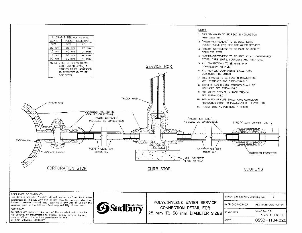
ALLOWABLE SIZE FOR PE PIPECOPPER POLYETHYLENE (PE)
SIZE SIZE I.D.20 mm 25 mm 21 mm25 mm 40 mm 31 mm40 mm 50 mm 41 mm50 mm 50 mm 41 mm
NOTE: SIZES OF STOPS (CURB&/0R CORPORATION) & FITTINGS TO BE INCREASEDTO CORRESPOND TO PEPIPE SIZES
SERVICE BOX
1. THIS STANDARD TO BE READ IN CONJUCTION WITH GSSS 701.
2. "INSERT-STIFFENERS" TO BE USED INSIDE POLYETHYLENE (PE) PIPE FOR WATER SERVICES.
3. "INSERT-STIFFENERS" TO BE MADE OF QUALITY STAINLESS STEEL.
4. "INSERT-STIFFENERS" TO BE USED AT ALL CORPORATION
STOPS. CURB STOPS, COUPLINGS AND ADAPTERS.
5. ALL CONNECTIONS TO BE MADE WITH COMPRESSION FITTINGS.
6. ALL METALLIC COMPONENTS SHALL HAVE CORROSION PROTECTION
7. THIS DRAWING TO BE READ IN CONJUNCTION WITH STANDARD DWG GSSD-1104.010.
8. CAPREOL AND LEVACK SERVICES SHALL BE INSULATED SEE GSSD-1104.011.
9. FOR WATER SERVICE IN ROCK TRENCH SEE GSSD-1104.011.
10. ROD & PIN IN CURB SHALL HAVE CORROSION PROTECTION PRIOR TO PLACEMENT OF SERVICE BOX
11. TRACER WIRE AS PER GSSD-1110.000.
TYPE 'K’ SOFT COPPER TUBE-
WATERMAIN
1
POLYETHYLENE PIPE SERIES 160
SOLID CONCRETE BLOCK OR SLAB
CORPORATION STOP CURB STOP
ORROSION PROTECTION
COUPLING
DISCLAIMER OF WARRANTYThe data is provided "as—is", without warranty of any kind either expressed or implied. Any and all liabilities for damage, direct or indirect, however caused, and resulting in any way by use of the supplied dota is the full and final responsibility of the user,
COPYRIGHTAll rights are reserved. No part of the supplied data may be reproduced, or transmitted to others, in any form or by any means, without the written permission of the CITY OF GREATER SUDBURY.
1 rOxatErlOandSudbiiiy25
DRAWN BY: STS/RF/MHD REV No: 3
POLYETHYLENE WATER SERVICE CONNECTION DETAIL FOR
mm TO 50 mm DIAMETER SIZES
DATE: 2003-03-03 REV DATE: 2013-01-01
SCALE: NTSCAD/FILE No.:
A1970-1 (1 OF 1)
APP’D: GSSD-1104.020
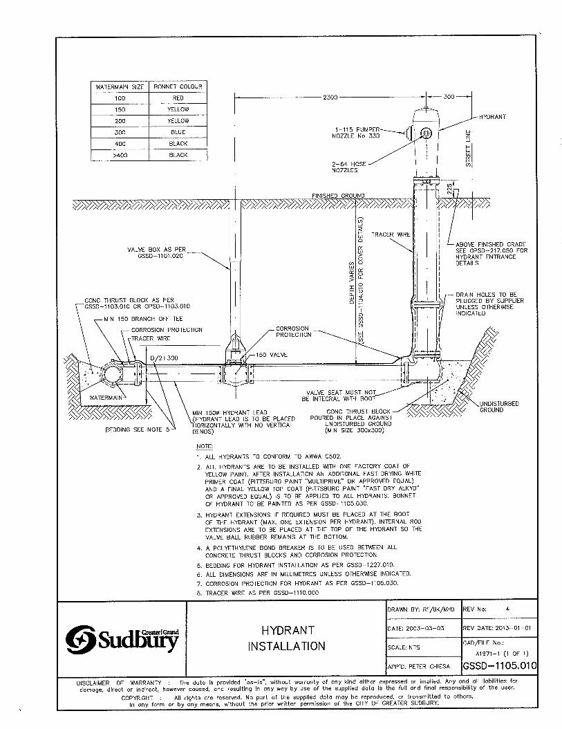
BONNET COLOUR
NOTE:
1. ALL HYDRANTS TO CONFORM TO AWWA C502.
2. ALL HYDRANTS ARE TO BE INSTALLED WITH ONE FACTORY COAT OF YELLOW PAINT. AFTER INSTALLATION AN ADDITONAL FAST DRYING WHITE PRIMER COAT (PITTSBURG PAINT ''MULTIPRIME" OR APPROVED EQUAL) AND A FINAL YELLOW TOP COAT (PITTSBURG PAINT "FAST DRY ALKYD" OR APPROVED EQUAL) IS TO BE APPUED TO ALL HYDRANTS. BONNET OF HYDRANT TO BE PAINTED AS PER GSSD-1105.030.
3. HYDRANT EXTENSIONS IF REQUIRED MUST BE PLACED AT THE BOOTOF THE HYDRANT (MAX. ONE EXTENSION PER HYDRANT). INTERNAL ROD EXTENSIONS ARE TO BE PLACED AT THE TOP OF THE HYDRANT SO THE VALVE BALL RUBBER REMAINS AT THE BOTTOM.
4. A POLYETHYLENE BOND BREAKER IS TO BE USED BETWEEN ALL CONCRETE THRUST BLOCKS AND CORROSION PROTECTION
5.
6.
7.
B.
BEDDING FOR HYDRANT INSTALLATION AS PER GSSD-1227.010.
ALL DIMENSIONS ARE IN MILLIMETRES UNLESS OTHERWISE INDICATED.
CORROSION PROTECTION FOR HYDRANT AS PER GSSD-1105.030.
TRACER WIRE AS PER GSSD-1110.000
DRAWN BY: RF/BK/MHD REV No: 4
©Sudf^ HYDRANTINSTALLATION
DATE: 2003-03-03 REV DATE: 2013-01-01
SCALE: NTSCAD/FILE No.:
A1971-1 (1 OF 1)
APP'D: PETER CHIESA GSSD-1105.010DISCLAIMER OF WARRANTY : The data Is provided "as-is", without warranty of any kind either expressed or implied. Any and all liabilities fordamage, direct or indirect, however caused, and resulting in any way by use of the supplied data is the full and final responsibility of the user.
COPYRIGHT : All rights are reserved. No part of the supplied dota may be reproduced, or transmitted to others,in any form or by any means, without the prior written permission of the CITY OF GREATER SUDBURY.__________________________

HYDRANT AS_ PER GSSD-1105.010
WATERMAIN SIZE BONNET COLOUR
100 RED
150 YELLOW
200 YELLOW
300 BLUE
400 BLACK
>400 BLACK
DUCTILE IRON TEE
BONNET
CORROSION PROTECTION ■
DUCTILE IRON HYDRANT BOOT
NOTES
1. ALL DIMENSIONS ARE SHOWN IN MILLIMETRES UNLESS OTHERWISE INDICATED.
2. THIS STANDARD DRAWING IS TO BE READ IN CONJUNCTION WITH GSSS 703.
3. TRACER WRE AS PER GSSD-1110.000
©SudKEty CORROSION PROTECTION ON HYDRANT INSTALLATIONS
DRAWN BY: STS/RF/MHD
DATE: 2003-03-03
SCALE: NTS
APP’D:
REV No:
REV DATE: 2013-01-01
CAD/FILE No.:
A1972-1 (1 OF 1)
GSSD-1105.0301DISCLAIMER OF WARRANTY : The data is provided "as—is”, without warranty of any kind either expressed or implied. Any and all liabilities fordamage, direct or Indirect, however caused, and resulting in any way by use of the supplied data is the full and final responsibility of the user.
COPYRIGHT : All rights are reserved. No part of the supplied data may be reproduced, or transmitted to others,in any form or by any means, without the prior written permission of the CITY OF GREATER SUDBURY.
APPENDIX C:
Watermain Test Report/Procedures Form
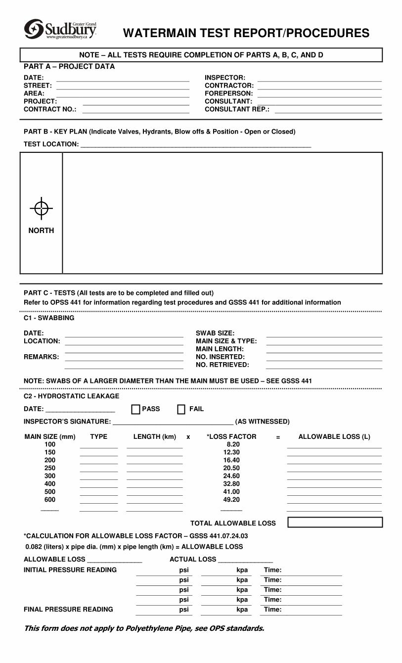
NOTE – ALL TESTS REQUIRE COMPLETION OF PARTS A, B, C, AND D
PART A – PROJECT DATA
DATE: INSPECTOR:
STREET: CONTRACTOR:
AREA: FOREPERSON:
PROJECT: CONSULTANT:
CONTRACT NO.: CONSULTANT REP.:
PART B - KEY PLAN (Indicate Valves, Hydrants, Blow offs & Position - Open or Closed)
TEST LOCATION: _______________________________________________________________
NORTH
PART C - TESTS (All tests are to be completed and filled out)
Refer to OPSS 441 for information regarding test procedures and GSSS 441 for additional information
C1 - SWABBING
DATE: SWAB SIZE:
LOCATION: MAIN SIZE & TYPE:
MAIN LENGTH:
REMARKS: NO. INSERTED:
NO. RETRIEVED:
NOTE: SWABS OF A LARGER DIAMETER THAN THE MAIN MUST BE USED – SEE GSSS 441
C2 - HYDROSTATIC LEAKAGE
DATE: ___________________ PASS FAIL
INSPECTOR’S SIGNATURE: _________________________________ (AS WITNESSED)
MAIN SIZE (mm) TYPE LENGTH (km) x *LOSS FACTOR = ALLOWABLE LOSS (L) 100 8.20
150 12.30
200 16.40
250 20.50
300 24.60
400 32.80
500 41.00
600 49.20
_____ ______
TOTAL ALLOWABLE LOSS
*CALCULATION FOR ALLOWABLE LOSS FACTOR – GSSS 441.07.24.03
0.082 (liters) x pipe dia. (mm) x pipe length (km) = ALLOWABLE LOSS
ALLOWABLE LOSS _______________ ACTUAL LOSS _______________
INITIAL PRESSURE READING psi kpa Time:
psi kpa Time:
psi kpa Time:
psi kpa Time:
FINAL PRESSURE READING psi kpa Time:
This form does not apply to Polyethylene Pipe, see OPS standards.
WATERMAIN TEST REPORT/PROCEDURES
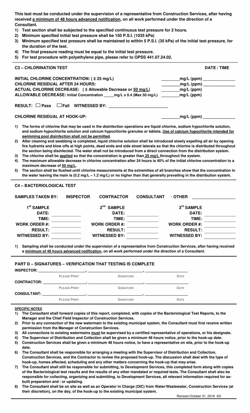
This test must be conducted under the supervision of a representative from Construction Services, after having
received a minimum of 48 hours advanced notification, on all work performed under the direction of a
Consultant.
1) Test section shall be subjected to the specified continuous test pressure for 2 hours.
2) Minimum specified initial test pressure shall be 150 P.S.I. (1035 kPa)
3) Minimum specified test pressure shall be maintained to within 5 P.S.I. (35 kPa) of the initial test pressure, for
the duration of the test.
4) The final pressure reading must be equal to the initial test pressure.
5) For test procedure with polyethylene pipe, please refer to OPSS 441.07.24.02.
C3 – CHLORINATION TEST DATE / TIME
INITIAL CHLORINE CONCENTRATION: ( ≥ 25 mg/L) ________mg/L (ppm) ______________
CHLORINE RESIDUAL AFTER 24 HOURS: ________mg/L (ppm) ______________
ACTUAL CHLORINE DECREASE: ( ≤ Allowable Decrease or 50 mg/L) ________mg/L (ppm)
ALLOWABLE DECREASE: Initial Concentration _____mg/L x 0.4 (Max 50 mg/L) ________mg/L (ppm)
RESULT: Pass Fail WITNESSED BY: __________________________
CHLORINE RESIDUAL AT HOOK-UP: ________mg/L (ppm) ______________
1) The forms of chlorine that may be used in the disinfection operations are liquid chlorine, sodium hypochlorite solution,
and sodium hypochlorite solution and calcium hypochlorite granules or tablets. Use of calcium hypochlorite intended for
swimming pool disinfection shall not be permitted.
2) After cleaning and swabbing is completed, liquid chlorine solution shall be introduced slowly expelling all air by opening
fire hydrants and blow offs at high points, dead ends and side street laterals so that the chlorine is distributed throughout
the section being disinfected. The water shall not be introduced from a direct connection from the distribution system.
3) The chlorine shall be applied so that the concentration is greater than 25 mg/L throughout the system.
4) The maximum allowable decrease in chlorine concentration after 24 hours is 40% of the initial chlorine concentration to a
maximum decrease of 50 mg/L.
5) The section shall be flushed until chlorine measurements at the extremities of all branches show that the concentration in
the water leaving the main is (0.2 mg/L – 1.2 mg/L) or no higher than that generally prevailing in the distribution system.
C4 – BACTERIOLOGICAL TEST
SAMPLES TAKEN BY: ���� INSPECTOR ���� CONTRACTOR ���� CONSULTANT OTHER ___________________
1st
SAMPLE
DATE:
2nd
SAMPLE
DATE:
3rd
SAMPLE
DATE:
TIME: TIME: TIME:
WORK ORDER #: WORK ORDER #: WORK ORDER #:
RESULT: RESULT: RESULT:
WITNESSED BY: WITNESSED BY: WITNESSED BY:
1) Sampling shall be conducted under the supervision of a representative from Construction Services, after having received
a minimum of 48 hours advanced notification, on all work performed under the direction of a Consultant.
PART D – SIGNATURES – VERIFICATION THAT TESTING IS COMPLETE
INSPECTOR: _______________________, ___________________________, _____________________
PLEASE PRINT SIGNATURE DATE
CONTRACTOR: _____________________, ___________________________, _____________________
PLEASE PRINT SIGNATURE DATE
CONSULTANT: _____________________, ___________________________, _____________________
PLEASE PRINT SIGNATURE DATE
SPECIFIC NOTES
1) The Consultant shall forward copies of this report, completed, with copies of the Bacteriological Test Reports, to the
Manager and the Chief Field Inspector of Construction Services.
2) Prior to any connection of the new watermain to the existing municipal system, the Consultant must first receive written
permission from the Manager of Construction Services.
3) All connections to existing watermains must be supervised by a certified representative of operations, or his designate.
4) The Supervisor of Distribution and Collection shall be given a minimum 48 hours notice, prior to the hook-up date.
5) Construction Services shall be given a minimum 48 hours notice, to have a representative on site, prior to the hook-up
date.
6) The Consultant shall be responsible for arranging a meeting with the Supervisor of Distribution and Collection,
Construction Services, and the Contractor to review the proposed hook-up. The discussion shall deal with the type of
hook-up, homes affected, scheduling and any other matters concerning the hook-up that may arise.
7) The Consultant shall still be responsible for submitting, to Development Services, this completed form along with copies
of the Bacteriological test results and the results of any other mandated or required tests. The Consultant shall also be
responsible for collecting, organizing and submitting, to Development Services, all relevant information required for as-
built preparation and / or updating.
8) The Consultant shall be on site as well as an Operator in Charge (OIC) from Water/Wastewater, Construction Services (at
their discretion), on the day, of the hook-up to the existing municipal system.
Revised October 31, 2018 AD