pss 2a-1c15 d - home - eurotec srl€¦ · · 2012-05-23product specifications l o g o pss...
TRANSCRIPT
FIELD DEVICES - PRESSUREProduct Specifications Logo
PSS 2A-1C15 D
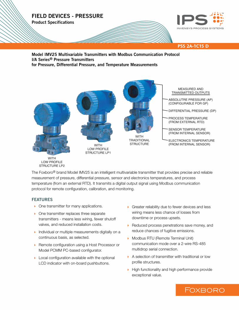
Model IMV25 Multivariable Transmitters with Modbus Communication Protocol
I/A Series® Pressure Transmitters
for Pressure, Differential Pressure, and Temperature Measurements
WITHLOW PROFILE
STRUCTURE LP2
WITHLOW PROFILE
STRUCTURE LP1
WITHTRADITIONALSTRUCTURE
ABSOLUTRE PRESSURE (AP)(CONFIGURABLE FOR GP)
DIFFERENTIAL PRESSURE (DP)
PROCESS TEMPERATURE(FROM EXTERNAL RTD)
SENSOR TEMPERATURE(FROM INTERNAL SENSOR)
ELECTRONICS TEMPERATURE(FROM INTERNAL SENSOR)
MEASURED ANDTRANSMITTED OUTPUTS
The Foxboro® brand Model IMV25 is an intelligent multivariable transmitter that provides precise and reliable measurement of pressure, differential pressure, sensor and electronics temperatures, and process temperature (from an external RTD). It transmits a digital output signal using Modbus communication protocol for remote configuration, calibration, and monitoring.
FEATURES
One transmitter for many applications.
One transmitter replaces three separate transmitters - means less wiring, fewer shutoff valves, and reduced installation costs.
Individual or multiple measurements digitally on a continuous basis, as selected.
Remote configuration using a Host Processor or Model PCMM PC-based configurator.
Local configuration available with the optional LCD indicator with on-board pushbuttons.
Greater reliability due to fewer devices and less wiring means less chance of losses from downtime or process upsets.
Reduced process penetrations save money, and reduce chances of fugitive emissions.
Modbus RTU (Remote Terminal Unit) communication mode over a 2-wire RS-485 multidrop serial connection.
A selection of transmitter with traditional or low profile structures.
High functionality and high performance provide exceptional value.
Foxboro

PSS 2A-1C15 DPage 2
Optional mounting bracket sets accommodate pipe or surface mounting of transmitters.
Aluminum housing has durable, corrosion-resistant epoxy finish; 316 ss housing also available; both meet NEMA 4X and IEC IP66.
Dual Seal Certified by CSA to meet ANSI/ISA 12.27.01-2003 requirements.
CE marked; complies with European EMC, NAMUR, ATEX, and PED European Directives.
Designed for hazardous area installations, and Agency flameproof and zone requirements.
Numerous options and accessories offered to expand the capabilities of these transmitters.
Standard 5-year warranty.
DIRECT CONNECTIVITY TO FOXBORO I/A Series OPEN INDUSTRIAL SYSTEM
The Model IMV25 can be connected directly to the I/A Series System using an I/A Series fieldbus module (FBM224 - Modbus Communication Interface Module).
OVERVIEW OF MODBUS COMMUNICATION
PROTOCOL(1)
The IMV25 combines a proven multivariable sensing technology with the Foxboro advanced development of the Modbus protocol. Communication with Host processors or a Model PCMM Configurator is made using the Modbus RTU (Remote Terminal Unit) mode over a 2-wire RS-485 multidrop serial connection. Please note that the Model PCMM Configurator is not configurable for multidrop communication and must therefore be connected to only one transmitter at a time. Refer to Figure 1 for a typical functional block diagram.
Figure 1. Typical Functional Block Diagram
The IMV25 uses the Modbus RTU mode, rather than the ASCII mode, for communication. The main advantage of the RTU mode is that its greater character density allows better data throughput than ASCII for the same baud rate. Each message must be transmitted in a continuous stream. The format for each byte in RTU mode is:
Coding System:– 8-bit binary, hexadecimal 0-9, A-F– Two hexadecimal characters contained in
each 8-bit field of the messageBits per Byte– One start bit– Eight data bits, least significant bit sent first– One bit for even/odd parity; no bit for no parity– One stop bit if parity is used; two bits if no
parityError Check Field: Cyclical Redundancy Check (CRC)
The IMV25 functions as a Modbus slave device. The paragraphs that follow list the Station Addresses supported Function Codes, and also Floating Point Support.
Station Addresses Supported
Station (or slave) addresses supported are in the range of 1 to 247.
(1) Implementation of Modbus in the IMV25 is based on the Gould Modbus Protocol Reference Guide, Document Number PI-MBUS-300, Rev. B.
CONVERTERRS-232
MODELPCMM
IMV25 IMV25
OTHERDEVICES
EXT.POWER
+EXT.
POWER
+
RS-485

PSS 2A-1C15 DPage 3
Function Codes Supported (see Table below)
Floating Point Support
Each Modbus register is a 16-bit register. Floating-point numbers in the IMV25 are each stored in two consecutive registers. Floating-point values must be retrieved by requesting the contents of both registers with the same poll command. Both registers of a floating-point value must be written in the same Modbus message. The floating-point numbers should be interpreted according to the IEEE-754 floating-point format for 32-bit numbers. Floating Point Byte order is selectable via four register legal values.
EXCEPTIONALLY HIGH PERFORMANCE
Accuracy to ±0.05% of spanLong term stability is excellent as drift is less than ±0.05% of URL per year over a 5-year period for both DP and P measurementsMinimized static pressure effect on DP by using pressure to compensate the DP measurementExcellent ambient temperature effect compensation due to characterization and microprocessor-based compensationTotal Probable Error (TPE) significantly better than typical competitive transmitters.
MODEL PCMM CONFIGURATOR
The Model PCMM Configurator is a software package that provides for the configuration of process variable parameters, transmitter calibration, and the monitoring of the process variables and configuration parameters. The configurator allows the user to:
Find transmitter connected in your system.
Configure RS-485 serial communication parameters and Modbus station address.
Read the device data for DP, AP, and also process temperature from the external RTD.
Configure the process variable parameters.
Calibrate the transmitter, if necessary.
View diagnostic information.
Refer to Figure 2 for a typical flow rate measurement application using the IMV25 and Model PCMM; and refer to PSS 2A-1Z3 H for Model PCMM specifications.
Figure 2. Typical Flow Rate Measurement Application
Code Description Comment
03 Read Holding Registers
Read the contents of a register in 4xxxx register address range (Holding Registers).
04 Read Input Registers
Read the contents of a register in 3xxxx register address range (Input Registers)
06 Preset Single Holding Register
Writes data to a single register in the 4xxxx register address range.
16 Preset Multiple Registers
Writes data to several holding registers. The registers must be in a block continuous 4xxxx register addresses.
MEASURED ANDTRANSMITTED OUTPUTS
ABSOLUTE PRESSURE(CONFIGURABLE FOR GP)DIFFERENTIAL PRESSUREPROCESS TEMPERATURE(FROM EXTERNAL RTD)
PIPELINE FLOW
ORIFICE PLATE AND FLANGE UNION
MODEL PCMMCONFIGUATOR
MULTIVARIABLETRANSMITTER
RTDSENSOR TEMPERATURE(FROM INTERNAL SENSOR)ELECTRONICS TEMP.(FROM INTERNAL SENSOR)
.
.
.
.
.

PSS 2A-1C15 DPage 4
HOST PROCESSOR INTERFACE
Although the IMV25 conforms to Modbus protocol, refer to Instruction Manual, MI 020-384, for details on transmitter operation and register reads and writes to design host interface software, or to evaluate compatibility of existing host software.
PROCESS CONNECTORS
Removable, gasketed connectors allow a wide range of selections, including 1/4 NPT, 1/2 NPT, R 1/4, R 1/2, and weld neck connectors.
SENSOR CORROSION PROTECTION
Industry standard 316L ss and Hastelloy C sensor materials are provided for corrosion protection. Refer to TI 37-75b for application of these wetted parts.
DUAL SEAL CERTIFICATION
The transmitter has been dual seal certified by CSA to meet ANSI/ISA 12.27.01-2003 requirements.
COMPLIANCE WITH EUROPEAN UNION DIRECTIVES
Complies with Electromagnetic Compatibility Requirements of European EMC Directive 89/336/EEC by conforming to the following CENELEC and IEC Standards: EN 50081-2, EN 50082-2, and IEC 61000-4-2 through61000-4-6.
Complies with NAMUR NE 21 Interference Immunity Requirement, and NAMUR 105 overrange and underrange annunciations.
Complies with all Applicable European Union Directives (“CE” Logo marked on product).
FLAMEPROOF AND EXPLOSIONPROOF DESIGN
Transmitter meets numerous agency requirements for use in hazardous area locations, and also meets Agency flameproof and zone requirements.
OPTIONAL LCD DIGITAL INDICATOR
A digital indicator with on-board pushbuttons is optionally available to display the measurement with a choice of units.Pushbuttons allow zero and span adjustments, as well as routine local configuration changes.
EASE OF INSTALLATION
Rotatable Topworks– Allows installation in tight places– Positions indicator in preferred direction– Eases field retrofitTwo Conduit Connections– 1/2 NPT, PG 13.5, or M20 threads– Provide for easy wiring– Allow self-draining of condensationWiring Guides and Terminations– Provide ease of wire entry and plenty of space– Use large, rugged screw terminals for easy
wire termination.
OPTIONAL MOUNTING BRACKET SETS
Standard and universal style mounting bracket sets have been developed to allow wide flexibility in transmitter mounting configurations consistent with installation requirements. Refer to Dimensions - Nominal section.
UNIQUE PROCESS COVER AND CELL BODY DESIGN
Biplanar Construction (Figure 3) maintains the traditional horizontal process connections and vertical mounting by providing a cell body contained between two process covers, while still achieving light weight, small size, and high static pressure rating. This provides easy retrofit of any conventional differential pressure transmitter, and also is easily mounted in the horizontal position with vertical process connections, when required.

PSS 2A-1C15 DPage 5
Process Covers (Figure 3) are fully supported by the cell body over their entire height. This prevents bending and results in a highly reliable seal. Also, this provides dimensional stability to the process covers, ensuring that they will always mate properly with 3-valve bypass manifolds.
Process Cover Bolts (Figure 3) are enclosed to minimize corrosion and to minimize early elongation with rapid temperature increases. The design makes it less likely for the transmitter to release process liquid during a fire.
Process Cover Gaskets are ptfe as standard; ptfe provides nearly universal corrosion resistance, and eliminates the need to select and stock various elastomers to assure process compatibility.
Light Weight means ease of handling, installation, and direct mounting without needing costly pipe stands.
TRANSMITTER STRUCTURES
Traditional and low profile structures (LP1 and LP2) are offered to accommodate and to provide flexibility in transmitter installations. See paragraphs below.
Traditional Structure
The traditional structure (Figure 4) utilizes the right angle design common to most DP transmitters in use throughout the world. Process connections are oriented 90 degrees from the transmitter centerline.
This traditional structure makes it easy to retrofit any transmitters of similar design.
Sensor cavity venting and draining is provided for both vertical and horizontal transmitter installation, using innovative tangential connections to the sensor cavity (Figures 5 and 6). Optional side vents are offered for sensor cavity venting in the upright position (Figure 7).
An extensive variety of process-wetted materials are available for the process covers on this highly versatile and widely used transmitter.
Figure 3. Biplanar Construction Shown with Traditional Horizontal Process Connections
Figure 4. Vertical Mounting ShowingProcess Connections at 90 degrees
Figure 5. Vertical Mounting - Cavity Draining
Figure 6. Horizontal Mounting - Cavity Venting, and Self-Draining into Process Line
CELL BODYENCLOSEDBOLTS
SUPPORTEDPROCESSCOVER
TRADITIONALSTRUCTURE
PROCESSCONNECTIONS
90˚
TRADITIONALSTRUCTURE
PROCESSCOVER DRAIN SCREW
TRADITIONALSTRUCTURE
VENT SCREWTRADITIONALSTRUCTURE

PSS 2A-1C15 DPage 6
Figure 7. Vertical Mounting - Cavity Venting,and Self-Draining into Process Line
Low Profile Structures
The low profile structures utilize an in-line design, placing the process connections in line with the transmitter centerline (Figure 8). This allows mounting of the transmitter in the upright position with the process connections facing downward, for connection to vertical process piping or for mounting directly to a three- or five-valve manifold (Figure 9).
The low profile structures provide a mounting style similar to that used by competitive Coplanar™ transmitters. This makes it easy to select Foxboro transmitters for both retrofit and new applications where this type of installation is desired.
Transmitters with the low profile structure can be attached directly to existing, installed Coplanar manifolds, such as the Rosemount Model 305RC or Anderson Greenwood Models MB3, MB5G, and MB5P, by use of an optional adapter plate (see Figure 10). Also, when assembled to the same process piping or manifold as a Coplanar transmitter, one of the electrical conduit connections is located within ± one inch of the similar conduit connection on the competitive transmitter, assuring ease of retrofit or conformance with installation design drawings.
All parts making up the low profile versions are identical to the parts in the traditional version except for the process covers and the external shape of the sensor cell body.
For user convenience, two types of low profile structures are offered, type LP1 and LP2. The process covers are the only transmitter parts that differ between structure types LP1 and LP2.
Refer to the sections that follow for further descriptions of low profile structures LP1 and LP2.
Figure 8. Low Profile Structure - LP1 Shown
Figure 9. LP1 Shown Directly Mounted to Manifold
Figure 10. LP1 Shown Mounted to a Coplanar Manifold using an Optional Intermediate Adapter Plate
OPTIONALSIDE VENTSHOWN
PLUG
TRADITIONALSTRUCTURE
IN-LINEPROCESSCONNECTION
LP1STRUCTURE
3 OR 5 VALVEMANIFOLD
LP1STRUCTURE
CoplanarMANIFOLD
ADAPTERPLATE
LP1STRUCTURE

PSS 2A-1C15 DPage 7
Low Profile Structure LP1 – Direct Mount
Structure LP1 is a compact, inexpensive, lightweight design for direct mounting to a separately mounted manifold or process piping. These transmitters are not typically bracket-mounted.
They are supplied as standard with a single vent/drain screw in the side of each process cover. In conjunction with the standard tangential venting and draining design, they are suitable for mounting either vertically (Figure 11) or horizontally, and are suitable for nearly all applications, including liquids, gases, and steam. For horizontal installation, they can simply be “turned over” (rotated 180 degrees - Figures 12 and 13) to orient the high and low pressure sides in the preferred locations. There is no need to unbolt process covers. The topworks housing can also be rotated, as shown, to orient the conduit connections in the desired position.
In the vertical, upright position, they are also self-draining and are ideal for gas flow rate service, when directly mounted to a manifold located above the horizontal pipeline. The vent screw can be omitted for this or other applications, if desired.
Figure 11. Upright Mounting
Figure 12. Horizontal Mounting with Vent Screw
Figure 13. Horizontal Mounting with Drain Screw
IN-LINEPROCESSCONNECTION
VENTSCREW
LP1STRUCTURE
PROCESSCONNECTION
VENTSCREW
H-L
LP1STRUCTURE
PROCESSCONNECTION
DRAINSCREW
L-H
LP1STRUCTURE
PSS 2A-1C15 DPage 8
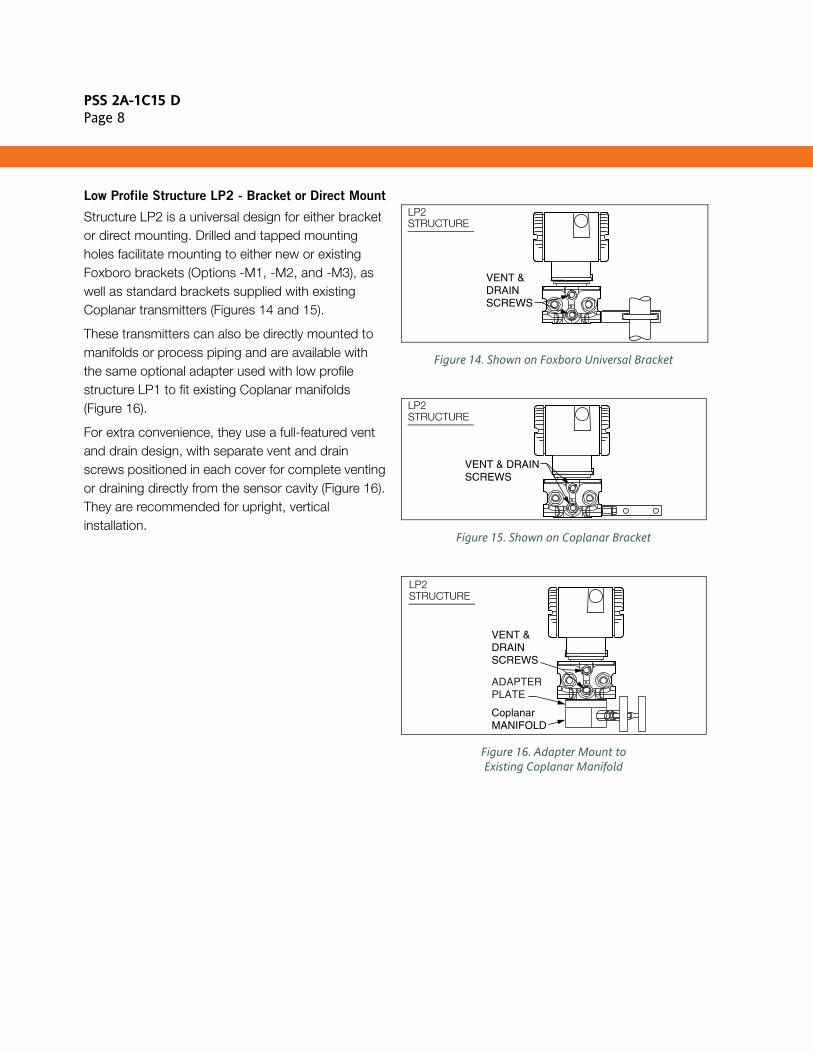
Low Profile Structure LP2 - Bracket or Direct Mount
Structure LP2 is a universal design for either bracket or direct mounting. Drilled and tapped mounting holes facilitate mounting to either new or existing Foxboro brackets (Options -M1, -M2, and -M3), as well as standard brackets supplied with existing Coplanar transmitters (Figures 14 and 15).
These transmitters can also be directly mounted to manifolds or process piping and are available with the same optional adapter used with low profile structure LP1 to fit existing Coplanar manifolds (Figure 16).
For extra convenience, they use a full-featured vent and drain design, with separate vent and drain screws positioned in each cover for complete venting or draining directly from the sensor cavity (Figure 16). They are recommended for upright, vertical installation.
Figure 14. Shown on Foxboro Universal Bracket
Figure 15. Shown on Coplanar Bracket
Figure 16. Adapter Mount to Existing Coplanar Manifold
VENT &DRAINSCREWS
LP2STRUCTURE
VENT & DRAINSCREWS
LP2STRUCTURE
VENT &DRAINSCREWS
CoplanarMANIFOLD
ADAPTERPLATE
LP2STRUCTURE

PSS 2A-1C15 DPage 9
FUNCTIONAL SPECIFICATIONS
Span and Range Limits for Differential Pressure Measurement
(a) Positive values indicate HI side of sensor at the high pressure, and negative values indicate LO side of sensor at the high pressure.(b) See Sensor URL table below for available combinations of DP and AP span codes.
Span and Range Limits for Absolute Pressure Measurement (a)
(a) Absolute Pressure measured directly; Gauge Pressure calculated from user-entered barometric pressure constant.(b) See Sensor URL table below for available combinations of DP and AP span codes.
Sensor URL, Maximum Static and Working Pressure (MWP), and Maximum Overrange Pressure
Span Code(b)
Span Limits Range Limits (a)
kPa inH2O mbar kPa inH2O mbar
L 0.12 and 2.5 0.5 and 10 1.2 and 25 -2.5 and +2.5 -10 and +10 -25 and +25
A 0.75 and 7.5 3 and 30 7.5 and 75 -7.5 and +7.5 -30 and +30 -75 and +75
B 0.5 and 50 2 and 200 5 and 500 -50 and +50 -200 and +200 -500 and +500
G 0.5 and 100 2 and 400 5 and 1000 -100 and +100 -400 and +400 -1000 and +1000
C 2.5 and 210 10 and 840 25 and 2100 -210 and +210 -840 and +840 -2100 and +2100
Span Code(b)
Span Limits Range Limits
MPa psia bar or kg/cm2 MPaa psiabara
or kg/cm2 abs.
D 0.02 and 2.1 3 and 300 0.21 and 21 0 and 2.1 0 and 300 0 and 21
G 0.07 and 3.5 10 and 500 0.7 and 35 0 and 3.5 0 and 500 0 and 35
E 0.21 and 10 30 and 1500 2.1 and 100 0 and 10 0 and 1500 0 and 100
H 0.42 and 20 60 and 3000 4.2 and 200 0 and 20 0 and 3000 0 and 200
F 3.4 and 36.5 500 and 5300 34 and 365 0 and 36.5 0 and 5300 0 and 365
AllowableSpan Code
CombinationsDP and AP
Sensor URL (DP and AP)
Maximum Static and Maximum Working
PressureMaximum Overrange
Pressure
DP AP DP AP MPaa psi MPaa psi
L and G 10 inH2O 500 psia 2.5 kPa 3.4 MPaa 3.4 500 5.2 750
A and G 30 inH2O 500 psia 7.5 kPa 3.4 MPaa 3.4 500 5.2 750
B and D 200 inH2O 300 psia 50 kPa 2.1 MPaa 2.1 300 3.1 450
B and E 200 inH2O 1500 psia 50 kPa 10 MPaa 10 1500 15 2250
B and H 200 inH2O 3000 psia 50 kPa 20 MPaa 20 3000 30 4500
B and F 200 inH2O 5300 psia 50 kPa 36.5 MPaa 36.5 5300 51.2 7420
G and G 400 inH2O 500 psia 100 kPa 3.4 MPaa 3.4 500 5.2 750
G and E 400 inH2O 1500 psia 100 kPa 10 MPaa 10 1500 15 2250
G and H 400 inH2O 3000 psia 100 kPa 20 MPaa 20 3000 30 4500
G and F 400 inH2O 5300 psia 100 kPa 36.5 MPaa 36.5 5300 51.2 7420
C and D 840 inH2O 300 psia 210 kPa 2.1 MPaa 2.1 300 3.1 450
C and E 840 inH2O 1500 psia 210 kPa 10 MPaa 10 1500 15 2250
C and H 840 inH2O 3000 psia 210 kPa 20 MPaa 20 3000 30 4500
C and F 840 inH2O 5300 psia 210 kPa 36.5 MPaa 36.5 5300 51.2 7420

PSS 2A-1C15 DPage 10
FUNCTIONAL SPECIFICATIONS (CONT.)
Impact of Certain Options on Maximum Static Pressure and Span and Range Limits (a)(b)
(a) Refer to Model Code section for application and restrictions related to the items listed in the table.(b) There is no impact (derating) when Options -B2, -D3, or -D7 are selected. The ratings for these options are the standard rating of
25 MPaa (3625 psia, 250 bara, or kg/cm2 abs).
Supply Voltage
9 to 30 V dc at 350 mW a specific Modbus power supply.
Output Signal and Configuration
Digital output. Configurable using the Host Processor, Model PCMM, or optional LCD Indicator.
Measured and Transmitted OutputsAbsolute Pressure (Configurable for Gauge Pressure; PGP = PAP - Patm)(2)
Differential PressureSensor TemperatureElectronics TemperatureProcess Temperature (from External RTD)
Process Temperature Measurement and Limits
MEASUREMENT
DIN/IEC, 2-, 3-, or 4-wire, 100 ohm, Platinum Resistance-Temperature-Detector (RTD)RANGE LIMITS
-200 and +850°C (-328 and +1562°F)
Zero and Span Adjustments
Zero and span adjustments can be initiated from the Model PCMM or optional LCD Indicator.
Suppressed Zero and Elevated Zero
Suppressed or elevated zero ranges acceptable as long as Span and Range Limits are not exceeded.
Zeroing for Nonzero-Based Ranges
Dual Function Zeroing from the LCD Indicator pushbuttons allows differential pressure zeroing with either zero differential or LRV differential applied. This greatly simplifies position effect zeroing on many pressure and level applications. The Host Processor, Model PCMM, or optional LCD Indicator, provides zeroing at any user-entered value.
Adjustable Damping (DP and Pressure)
The transmitter response time is normally 1.0 s, or the electronically adjustable setting of 0.00 (none), 0.25, 0.50, 1, 2, 4, 8, 16, or 32 seconds, whichever is greater, for a 90% recovery from an 80% input step as defined in ANSI/ISA S51.1.
Field Wiring Reversal
Plus (+) and minus (–) terminals are provided on the terminal block for power input. No transmitter damage if field power wires are reversed.
Write Protect Jumper
Write protection is set with a jumper that can be positioned to lock out configurators from making transmitter database changes.
Communication
Modbus RTU mode over a 2-wire RS-485 multidrop serial connection.
Option Description (Also see Model Code) Span and Range Limits Derated to:
-B3 B7M Bolts and Nuts (NACE) 20 MPaa (2900 psia, 200 bara or kg/cm2 abs)
-D1 DIN Construction 16 MPaa (2320 psia, 160 bara or kg/cm2 abs)
-D5 or -B1 DIN Construction or 316 ss Bolting 15 MPaa (2175 psia, 150 bara or kg/cm2 abs)
-D2, -D4, -D6, or -D8 DIN Construction 10 MPaa (1500 psia, 100 bara or kg/cm2 abs)
(2) Patm is a user-entered barometric pressure constant.

PSS 2A-1C15 DPage 11
FUNCTIONAL SPECIFICATIONS (CONT.)
Communication Rate
1200, 2400, 4800, 9600, 19 200, or 38 400 baud, user selectable. The default value is 9600 baud.
Communication Response Delay
User selectable between 0 and 65 535 ms. The default value is 0 ms.
Configuration and Calibration Data
Factory characterization data, and user configuration and calibration data, are stored in the sensor. This means that the electronics module can be replaced without the need for reconfiguration or recalibration.
Configuration Capability (Also see NOTE below)
NOTENumerous parameters can be configured and/or displayed, such as electronic damping, transmitter calibration, tag data, etc. See applicable configuration documents for details.
Available Units for Calibrated Range
Minimum Allowable Absolute Pressure vs.
Transmitter Temperature
WITH SILICONE FILL FLUID
Full vacuum: up to 121 °C (250°F)WITH INERT FILL FLUID
Refer to Figure 17.
Figure 17. Minimum Allowable Absolute Pressure vs. Transmitter Temperature, Inert FC-43, 2.6 cs at 25°C (77°F)
Optional LCD Indicator (Figure 18)
Indicator Provides:
Two Lines; five numeric characters on top line (four when a minus sign is needed) and seven alphanumeric characters on bottom line.Measurement Readout; value on top line and units label on bottom line.Configuration and Calibration Prompts.Configuration Functions (with Pushbuttons)Calibration Functions (with Pushbuttons)
Figure 18. LCD Indicator with Pushbuttons
Variable Measurement
Primary Variable Differential Pressure (DP)
Secondary Variable Absolute Pressure (AP)
Tertiary Variable Process Temperature
Pressure Temp.
inH2O mH2O Pa mbar psi C
ftH2O inHg kPa bar atm F
mmH2O mmHg MPa g/cm2 R
cmH2O cmHg torr kg/cm2 K
TEMPERATURE, ˚F
TEMPERATURE, ˚C
AB
SO
LUT
E P
RE
SS
UR
E, m
mH
g -30 0 30 60 40 120
-25 0 50 100 150 200 250
140
120
100
80
60
40
20
0
FLUORINERTFC-43 FLUIDOPERATING
AREA
TOPWORKSWITH COVERREMOVED
OPTIONALLCD INDICATOR
"ENTER"PUSHBUTTON
"NEXT"PUSHBUTTON
NEXT ENTER
PSS 2A-1C15 DPage 12
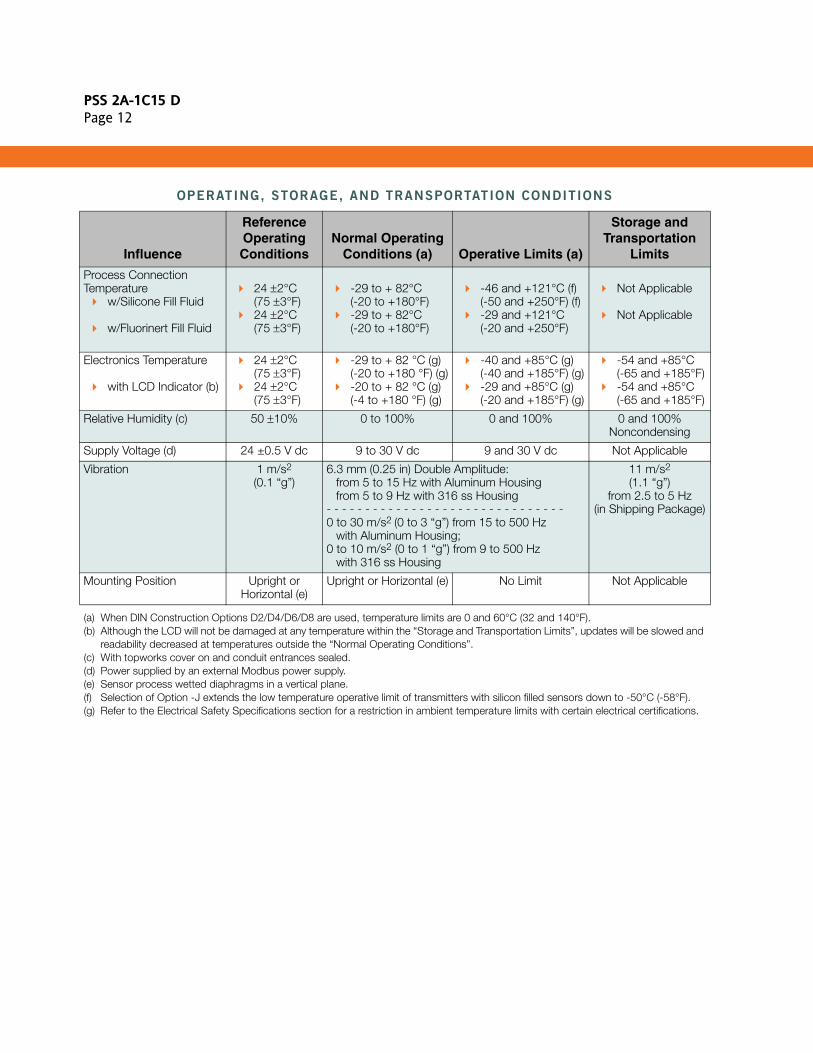
OPERATING, STORAGE, AND TRANSPORTATION CONDITIONS
(a) When DIN Construction Options D2/D4/D6/D8 are used, temperature limits are 0 and 60°C (32 and 140°F).(b) Although the LCD will not be damaged at any temperature within the “Storage and Transportation Limits”, updates will be slowed and
readability decreased at temperatures outside the “Normal Operating Conditions”.(c) With topworks cover on and conduit entrances sealed.(d) Power supplied by an external Modbus power supply.(e) Sensor process wetted diaphragms in a vertical plane.(f) Selection of Option -J extends the low temperature operative limit of transmitters with silicon filled sensors down to -50°C (-58°F).(g) Refer to the Electrical Safety Specifications section for a restriction in ambient temperature limits with certain electrical certifications.
Influence
Reference OperatingConditions
Normal Operating Conditions (a) Operative Limits (a)
Storage and Transportation
Limits
Process Connection Temperature
w/Silicone Fill Fluid
w/Fluorinert Fill Fluid
24 ±2°C(75 ±3°F)24 ±2°C(75 ±3°F)
-29 to + 82°C(-20 to +180°F)-29 to + 82°C(-20 to +180°F)
-46 and +121°C (f)(-50 and +250°F) (f)-29 and +121°C(-20 and +250°F)
Not Applicable
Not Applicable
Electronics Temperature
with LCD Indicator (b)
24 ±2°C(75 ±3°F)24 ±2°C(75 ±3°F)
-29 to + 82 °C (g)(-20 to +180 °F) (g)-20 to + 82 °C (g)(-4 to +180 °F) (g)
-40 and +85°C (g)(-40 and +185°F) (g)-29 and +85°C (g)(-20 and +185°F) (g)
-54 and +85°C(-65 and +185°F)-54 and +85°C(-65 and +185°F)
Relative Humidity (c) 50 ±10% 0 to 100% 0 and 100% 0 and 100%Noncondensing
Supply Voltage (d) 24 ±0.5 V dc 9 to 30 V dc 9 and 30 V dc Not Applicable
Vibration 1 m/s2
(0.1 “g”)6.3 mm (0.25 in) Double Amplitude:
from 5 to 15 Hz with Aluminum Housingfrom 5 to 9 Hz with 316 ss Housing
- - - - - - - - - - - - - - - - - - - - - - - - - - - - - - -0 to 30 m/s2 (0 to 3 “g”) from 15 to 500 Hz
with Aluminum Housing;0 to 10 m/s2 (0 to 1 “g”) from 9 to 500 Hz
with 316 ss Housing
11 m/s2
(1.1 “g”)from 2.5 to 5 Hz
(in Shipping Package)
Mounting Position Upright or Horizontal (e)
Upright or Horizontal (e) No Limit Not Applicable
PSS 2A-1C15 DPage 13
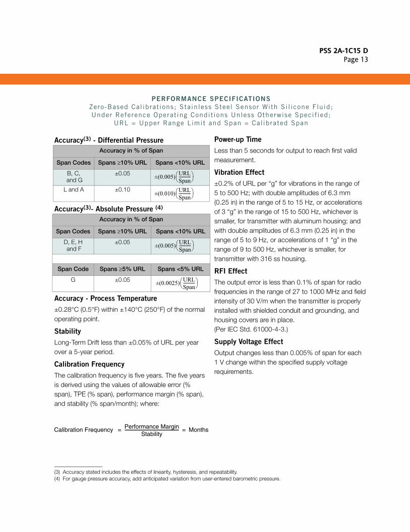
PERFORMANCE SPECIFICATIONS
Zero-Based Cal ibrat ions; Stainless Steel Sensor With Si l icone Fluid; Under Reference Operat ing Condit ions Unless Otherwise Specif ied;
URL = Upper Range Limit and Span = Calibrated Span
Accuracy(3) - Differential Pressure
Accuracy(3)- Absolute Pressure (4)
Accuracy - Process Temperature
±0.28°C (0.5°F) within ±140°C (250°F) of the normal operating point.
Stability
Long-Term Drift less than ±0.05% of URL per year over a 5-year period.
Calibration Frequency
The calibration frequency is five years. The five years is derived using the values of allowable error (% span), TPE (% span), performance margin (% span), and stability (% span/month); where:
Power-up Time
Less than 5 seconds for output to reach first valid measurement.
Vibration Effect
±0.2% of URL per “g” for vibrations in the range of 5 to 500 Hz; with double amplitudes of 6.3 mm (0.25 in) in the range of 5 to 15 Hz, or accelerations of 3 “g” in the range of 15 to 500 Hz, whichever is smaller, for transmitter with aluminum housing; and with double amplitudes of 6.3 mm (0.25 in) in the range of 5 to 9 Hz, or accelerations of 1 “g” in the range of 9 to 500 Hz, whichever is smaller, for transmitter with 316 ss housing.
RFI Effect
The output error is less than 0.1% of span for radio frequencies in the range of 27 to 1000 MHz and field intensity of 30 V/m when the transmitter is properly installed with shielded conduit and grounding, and housing covers are in place. (Per IEC Std. 61000-4-3.)
Supply Voltage Effect
Output changes less than 0.005% of span for each 1 V change within the specified supply voltage requirements.
Accuracy in % of Span
Span Codes Spans ≥10% URL Spans <10% URL
B, C, and G
±0.05
L and A ±0.10
(3) Accuracy stated includes the effects of linearity, hysteresis, and repeatability.
Accuracy in % of Span
Span Codes Spans ≥10% URL Spans <10% URL
D, E, H and F
±0.05
Span Code Spans ≥5% URL Spans <5% URL
G ±0.05
(4) For gauge pressure accuracy, add anticipated variation from user-entered barometric pressure.
±(0.005) URLSpan------------⎝ ⎠
⎛ ⎞
±(0.010) URLSpan------------⎝ ⎠
⎛ ⎞
±(0.005) URLSpan------------⎝ ⎠
⎛ ⎞
±(0.0025) URLSpan------------⎝ ⎠
⎛ ⎞
Calibration Frequency Performance MarginStability
------------------------------------------------------ Months= =

PSS 2A-1C15 DPage 14
PERFORMANCE SPECIFICATIONS (CONT.)
Static Pressure Effect on Differential Pressure
The zero and span shift for a 0.7 MPa, 100 psi, change in static pressure is:
ZERO SHIFT
SPAN SHIFT
±0.01% of Reading
Position Effect
Transmitter may be mounted in any position. Any zero effect caused by mounting position can be eliminated by rezeroing. There is no span effect.
Ambient Temperature Effect
Total effect for a 28°C (50°F) change within Normal Operating Condition Limits is ±(0.03% URL + 0.06% Span); except the effect on differential pressure for DP Span Codes A and L is ±(0.18% URL + 0.025% Span). Also for AP Span Code H, the effect is ±(0.02% URL +0.06% Span); and for AP Span Code F, the effect is ±(0.15% URL +0.06% Span).
Switching and Indirect Lightning Transients
The transmitter can withstand a transient surge up to 2000 V common mode or 1000 V normal mode without permanent damage. Output shift is <1.0%. (Per ANSI/IEEE C62.41-1980 and IEC Std. 61000-4-5.)
Electromagnetic Compatibility
Complies with NAMUR NE 21 Interference Immunity Requirement, and NAMUR 105 overrange and underrange annunciations.
Complies with Electromagnetic Compatibility Requirements of European EMC Directive 89/336/EEC by conforming to the following CENELEC and IEC Standards: EN 50081-2, EN 50082-2, IEC 61000-4-2 through 61000-4-6
Allowable Span Limit Code Combinations
Zero Shift for a 0.7 MPa (100 psi) Change:
DP AP in % of URL
L G ±0.150
A G ±0.050
B D ±0.007
B E ±0.010
B H ±0.010
B F ±0.010
G G ±0.004
G E ±0.005
G H ±0.005
G F ±0.005
C D ±0.002
C E ±0.004
C H ±0.004
C F ±0.004
PSS 2A-1C15 DPage 15
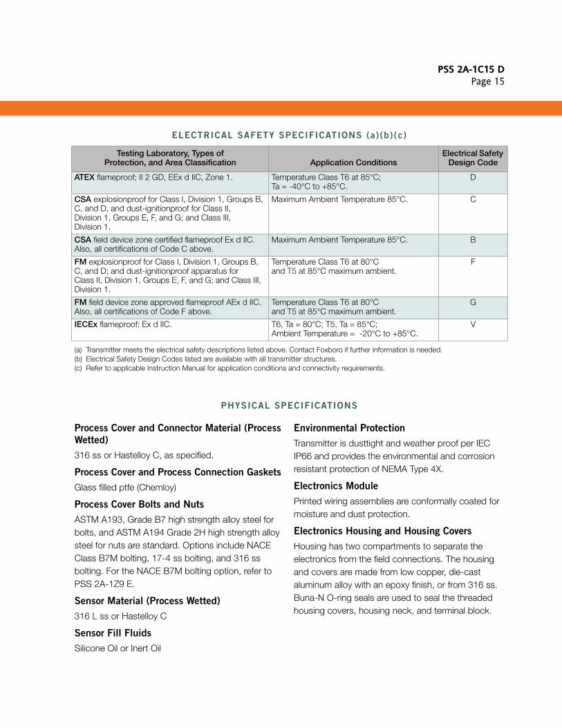
ELECTRICAL SAFETY SPECIFICATIONS (a)(b)(c)
(a) Transmitter meets the electrical safety descriptions listed above. Contact Foxboro if further information is needed.(b) Electrical Safety Design Codes listed are available with all transmitter structures.(c) Refer to applicable Instruction Manual for application conditions and connectivity requirements.
PHYSICAL SPECIFICATIONS
Process Cover and Connector Material (Process
Wetted)
316 ss or Hastelloy C, as specified.
Process Cover and Process Connection Gaskets
Glass filled ptfe (Chemloy)
Process Cover Bolts and Nuts
ASTM A193, Grade B7 high strength alloy steel for bolts, and ASTM A194 Grade 2H high strength alloy steel for nuts are standard. Options include NACE Class B7M bolting, 17-4 ss bolting, and 316 ss bolting. For the NACE B7M bolting option, refer to PSS 2A-1Z9 E.
Sensor Material (Process Wetted)
316 L ss or Hastelloy C
Sensor Fill Fluids
Silicone Oil or Inert Oil
Environmental Protection
Transmitter is dusttight and weather proof per IEC IP66 and provides the environmental and corrosion resistant protection of NEMA Type 4X.
Electronics Module
Printed wiring assemblies are conformally coated for moisture and dust protection.
Electronics Housing and Housing Covers
Housing has two compartments to separate the electronics from the field connections. The housing and covers are made from low copper, die-cast aluminum alloy with an epoxy finish, or from 316 ss. Buna-N O-ring seals are used to seal the threaded housing covers, housing neck, and terminal block.
Testing Laboratory, Types ofProtection, and Area Classification Application Conditions
Electrical Safety Design Code
ATEX flameproof; II 2 GD, EEx d IIC, Zone 1. Temperature Class T6 at 85°C;Ta = -40°C to +85°C.
D
CSA explosionproof for Class I, Division 1, Groups B, C, and D, and dust-ignitionproof for Class II, Division 1, Groups E, F, and G; and Class III, Division 1.
Maximum Ambient Temperature 85°C. C
CSA field device zone certified flameproof Ex d IIC. Also, all certifications of Code C above.
Maximum Ambient Temperature 85°C. B
FM explosionproof for Class I, Division 1, Groups B, C, and D; and dust-ignitionproof apparatus for Class II, Division 1, Groups E, F, and G; and Class III, Division 1.
Temperature Class T6 at 80°Cand T5 at 85°C maximum ambient.
F
FM field device zone approved flameproof AEx d IIC. Also, all certifications of Code F above.
Temperature Class T6 at 80°C and T5 at 85°C maximum ambient.
G
IECEx flameproof; Ex d IIC. T6, Ta = 80°C; T5, Ta = 85°C;Ambient Temperature = -20°C to +85°C.
V

PSS 2A-1C15 DPage 16
PHYSICAL SPECIFICATIONS (CONT.)
Electrical Connections
Field and RTD sensor wires enter through 1/2 NPT, PG 13.5, or M20 threaded entrances, as specified, on either side of the electronics housing. Wires terminate under screw terminal assemblies on the terminal block in the field terminal compartment. Refer to Figure 19.
Mounting Position
The transmitter may be mounted in any orientation.
Approximate Mass (with Process Connectors)
4.2 kg (9.2 lb) – with Traditional Structure
Add 0.1 kg (0.2 lb) – with Low Profile Structure LP1
Add 0.8 kg (1.8 lb) – with Low Profile Structure LP2
Add 1.1 kg (2.4 lb) – with 316 ss Housing
Add 0.2 kg (0.4 lb) – with LCD Indicator Option
Dimensions
See “Dimensions – Nominal” section and Dimensional Print DP 020-432.
Figure 19. Field Terminal Connections
TERMINAL BLOCK LOCATED INFIELD TERMINAL COMPARTMENTOF ELECTRONICS HOUSING
0.138-32 (+) AND (-)POWER TERMINALSCREWS
INTERNAL EARTH(GROUND) TERMINALSCREW, O.112-40
0.112-40TERMINAL SCREWSFOR 2-, 3-, OR 4-WIRERTDs.
0.138-32 (+) AND (-)TERMINAL SCREWSFOR RS-485 AND FOR MODEL PCMMCONFIGURATOR(+) AND (-) CONNECTIONS
1 2
+
B(-)A(+)
4
3
G

PSS 2A-1C15 DPage 17
MODEL CODE
DescriptionI/A Series Multivariable Transmitter
ModelIMV25
Electronics Versions and Output SignalIntelligent; Digital Modbus (Version -M) -M
Structure Code - Process Covers, Sensor Material, and Sensor Fill FluidWith Traditional StructureCovers Sensor Fill Fluid316 ss 316L ss Silicone316 ss 316L ss Inert
316 ss Hastelloy C Silicone316 ss Hastelloy C Inert
Hastelloy C Hastelloy C SiliconeHastelloy C Hastelloy C Inert
2223
2627
4647
With Low Profile Structure LP1Covers Sensor Fill Fluid316 ss 316L ss Silicone316 ss 316L ss Inert
316 ss Hastelloy C Silicone316 ss Hastelloy C Inert
LLLM
LCLD
With Low Profile Structure LP2Covers Sensor Fill Fluid316 ss 316L ss Silicone316 ss 316L ss Inert
316 ss Hastelloy C Silicone316 ss Hastelloy C Inert
5253
5657
Span Limits - Differential Pressure (DP) MeasurementkPa inH2O mbar Available with: (a)0.12 and 2.5 0.5 and 10 1.2 and 25 AP Span Limit Code G only0.75 and 7.5 3 and 30 7.5 and 75 AP Span Limit Code G only0.5 and 50 2 and 200 5 and 500 AP Span Limit Codes D, E, H and F only0.5 and 100 2 and 400 5 and 1000 AP Span Limit Codes G, E, H and F only2.5 and 210 10 and 840 25 and 2100 AP Span Limit Codes D, E, H and F only
LABGC
Span Limits - Absolute Pressure (AP) Measurement (Absolute Measured; Gauge Calculated)MPaa psia bara or kg/cm2 abs Available with: (a)0.02 and 2.1 3 and 300 0.21 and 21 DP Span Limit Codes B and C only0.07 and 3.4 10 and 500 0.7 and 34 DP Span Limit Codes L, A, and G only0.21 and 10 30 and 1500 2.1 and 100 DP Span Limit Codes B, G, and C only0.42 and 20 60 and 3000 4.2 and 200 DP Span Limit Codes B, G, and C only3.4 and 36.5 500 and 5300 34 and 365 DP Span Limit Codes B, G, and C only
DGEHF
Other MeasurementsTemperature - Terminal Block supports Connection of External, 100 ohm Platinum RTD (DIN/IEC) 1
Model Code continued on next page

PSS 2A-1C15 DPage 18
MODEL CODE (CONT.)
Description (Cont.) Model
Process Connector Type (Material Same as Process Cover Material)None, Covers tapped for 1/4 NPT
1/4 NPT:316 ss with Structure Codes 22 to 27, 52 to 57, and LL, LM, LC, and LD
1/2 NPT:316 ss with Structure Codes 22 to 27, 52 to 57, and LL, LM, LC, and LDHastelloy C with Structure Codes 46 and 47
Rc 1/4:316 ss with Structure Codes 22 to 27, 52 to 57, and LL, LM, LC, and LD
Rc 1/2316 ss with Structure Codes 22 to 27, 52 to 57, and LL, LM, LC, and LDHastelloy C with Structure Codes 46 and 47
Schedule 80 Welding Neck:316 ss with Structure Codes 22 to 27, 52 to 57, and LL, LM, LC, and LD
0
1
2
3
4
6
Conduit Connection and Housing Material1/2 NPT Connection, Aluminum HousingPG 13.5 Connection, Aluminum Housing (Available with Electrical Safety Codes D and V only)1/2 NPT Connection, 316 ss HousingPG 13.5 Connection, 316 ss Housing (Available with Electrical Safety Codes D and V only)M20 Connection, Aluminum Housing (Available with Electrical Safety Codes D and V only)M20 Connection, 316 ss Housing (Available with Electrical Codes D and V only)
123456
Electrical Safety (See Electrical Safety Specifications Section for Description and Approval Status)ATEX flameproof; II 2 GD, EEx d IIC, Zone 1 (m)CSA Division 1 explosionproof and dust-ignitionproof
Also Dual Seal Certified per ANSI/ISA 12.27.01-2003.CSA Zone Certified Ex d IIC; also all certifications of Code C above (m)
Also Dual Seal Certified per ANSI/ISA 12.27.01-2003.FM Division 1 explosionproof and dust-ignitionproofFM Zone Approved AEx d IIC; also all certifications of Code F above (m)IECEx Certified Flameproof, Ex d, IIC (m)
DC
B
FGV
Optional Selections (See PSS 2A-1Z9 E for Options/Accessories not in Model Code)Refer to Optional Selection descriptions that follow.
Mounting Bracket Set (n)Standard Style Painted Steel Bracket with Plated Steel BoltsStandard Style Stainless Steel Bracket with Stainless Steel BoltsUniversal Style Stainless Steel Bracket with Stainless Steel Bolts
-M1-M2-M3
Digital Indicator with PushbuttonsDigital Indicator, Pushbuttons, and Window Cover -L1
Model Code continued on next page

PSS 2A-1C15 DPage 19
Optional Selections (Cont.) Model
DIN 19213 Construction used with Process Connector Code “0” and 316 ss Covers Only (b)Single Ended Process Cover with M10, B7 Steel Bolting (p)Double Ended Process Cover with M10, B7 Steel Bolting (Blind Kidney Flange on Back) (c)(d) (p)Single Ended Process Cover with 7/16 in, B7 Steel BoltingDouble Ended Process Cover with 7/16 in, B7 Steel Bolting (Blind Kidney Flange on Back) (c)(d) (p)Single Ended Process Cover with 7/16 in, 316 ss Bolting (p)Double Ended Process Cover with 7/16 in, 316 ss Bolting (Blind Kidney Flange on Back) (c)(d) (p)Single Ended Process Cover with 7/16 in, 17-4 ss BoltingDouble Ended Process Cover with 7/16 in, 17-4 ss Bolting (Blind Kidney Flange on Back) (c)(d) (p)
-D1-D2-D3-D4-D5-D6-D7-D8
Cleaning and PreparationUnit Degreased - for Silicone Filled Sensors Only
(Not for Oxygen/Chlorine/Other Fluids that may react with Silicone)Cleaned and Prepared for Oxygen Service - for Inert Filled Sensors OnlyCleaned and Prepared for Chlorine Service - for Inert Filled Sensors Only
(includes 17-4 ss bolting; therefore do not also specify Option -B2)
-X1
-X2-X3
Bolting for Process Covers - Not Available with DIN 19213 Construction316 ss Bolts and Nuts (e) (p)17-4 ss Bolts and Nuts (e)B7M Bolts and Nuts (e)(f) (p)
-B1-B2-B3
Conduit ConnectorsHawke-Type 1/2 NPT Cable Gland for use with Conduit Connection Codes 1 and 3 (g)M20 Conduit Thread Adapter for use with Conduit Connection Codes 1 and 3 (g)
-A1-A3
Electronics Housing FeaturesCustody Transfer Lock and Seal -Z2
Tubing Connectors316 ss, Connecting 6 mm Tubing to 1/4 NPT Process Connector (h)316 ss, Connecting 12 mm Tubing to 1/2 NPT Process Connector (j)
-E3-E4
Vent Screw in Process CoverSupply Vent Screw in Side of Each Process Cover
(Available only on Traditional Process Cover Structure Codes 22 to 47)Omit Vent Screw in Side of Each Process Cover
(Available only on Type LP1 Low Profile Process Cover Structures Codes LL, LM, LC, and LD)
-V
-V1
Adapter Plate, Bolts, and Gaskets for Direct Mount to Competitive Manifolds (k)See inside pages for manifold compatibility.
Adapter Set for MC Coplanar Manifolds, B7 Bolts (not with options -B1, -B2, or -B3)Adapter Set for MC Coplanar Manifolds, 316 ss Bolts (requires -B1 option)Adapter Set for MC Coplanar Manifolds, 17-4 ss Bolts (requires -B2 option)Adapter Set for MC Coplanar Manifolds, B7M Bolts (requires -B3 option)Adapter Set for MT3 Coplanar Manifolds, Traditional Flange, B7 Bolts (not with options -B1, -B2, or -B3)Adapter Set for MT3 Coplanar Manifolds, Traditional Flange, 316 ss Bolts (requires -B1 option)Adapter Set for MT3 Coplanar Manifolds, Traditional Flange, 17-4 ss Bolts (requires -B2 option)Adapter Set for MT3 Coplanar Manifolds, Traditional Flange, B7M Bolts (requires -B3 option)
-P1-P2-P3-P4-P5-P6-P7-P8
Model Code continued on next page
MODEL CODE (CONT.)

PSS 2A-1C15 DPage 20
(a) See Span and Range Limits tables in Functional Specifications section for allowable DP and AP Span Limit Code combinations.(b) Not available with:
- Vent Screw Options -V and -V1.- Absolute Pressure Span Limit Code F.- Low Profile Structure Codes 50 to 57.
(c) DIN 19213 Construction Codes -D2, -D4, -D6, and -D8 are not available with Low Profile Structure Codes 52 to 57, and LL, LM, LC, and LD.
(d) Temperature limits are 0 and 60°C (32 and 140°F) with Options -D2, -D4, -D6, and -D8. Also these options are not available with Mounting Set Options -M1, -M2, or -M3.
(e) Not available with DIN 19213 Construction Options -D1 to -D8. Select Option Codes -D5 to -D8 to get stainless bolting on DIN 19213 Transmitters.
(f) Selection of Option -B3 normally requires selection of Auxiliary Specification (AS) MR-01 (NACE Standard MR 01-75).(g) Not available with Electrical Safety Codes C and F.(h) Only available with Structure Codes 22 and 23; and only with Process Connector Codes 0 and 1.(j) Only available with Structure Codes 22 and 23; and only with Process Connector Code 2.(k) Adapter plate options -P1 to -P8 are not available with:
– Process Connector Codes 1-6.– DIN Construction Options -D1, -D2, -D4, -D5, -D6, -D7, and -D8.
(l) Low Temperature Option -J not available with:– Structures with Inert Fill– DIN Construction Option Codes -D2, -D4, -D6, and -D8
(m) A cover lock is provided as standard with Electrical Safety Codes D, B, G, and V.(n) When a Mounting Bracket Set is selected with Low Profile Structures LL, LM, LC, and LD, the Process Connector Code must be “0”.(p) DIN 19213 Construction Option Codes -D1, -D2, -D4, -D5, -D6, and -D8, and Bolting Option Codes -B1 and -B3 are pressure
derated. Refer to Derating table in Functional Specifications section.
Optional Selections (Cont.) Model
Instruction Books (Common MI, Brochure, and Full Documentation Set on CD-ROM is Standard)Without Instruction Book and CD; only “Getting Started” brochure is supplied
-K1Miscellaneous Optional SelectionsSupplemental Customer Tag (Stainless Steel Tag wired onto Transmitter)Low Temperature Operative Limit of -50°C(-58°F) (l)
-T-J
Example: IMV25-M22BD121F-M1L1
MODEL CODE (CONT.)

PSS 2A-1C15 DPage 21
SUGGESTED RFQ SPECIFICATIONS
The manufacturer shall provide field-mounted, multivariable transmitter(s) featuring Modbus Communication Protocol. They shall provide remote digital communications capability for measuring absolute pressure, differential pressure, and temperature, and transmitting a digital output signal for use in a standard two-wire dc supply voltage system. The specifications for this Multivariable transmitter are as follows:
Communication Protocol: Modbus - RTU Mode
Remote Communications: Must not interfere with output
Accuracy: Digital Output: ±0.05% of calibrated span
Damping: Settable for a range of none to 32 seconds
RFI Protection: 0.1% error between 27 and 1000 MHz at 30 V/m field intensity
Span Limits: Absolute Pressure Measurement3 and 300, 10 and 500, 30 and 1500, 60 and 3000, and 500 and 5300 psi, or SI and Metric Equivalents
Differential Pressure Measurement0.5 and 10, 3 and 30, 2 and 200, 2 and 400, and 10 and 840 inH2O, or SI and Metric Equivalents
Process Temperature: Transmitter includes terminals to receive either a 2-, 3-, or 4-wire, 100 ohm, platinum DIN/IEC RTD to measure process temperature.Range Limits are -200 and +850°C (-328 and +1562°F).
Mounting: On process piping, optional mounting bracket, or to a manifold.
Input Connection: With process connectors to accept 1/4 NPT, 1/2 NPT, Rc 1/4 or Rc 1/2, 1/2 Schedule 80 welding neck
Housing: Aluminum housing with epoxy finish, or 316 ss housing; with 1/2 NPT, PG 13.5, or M20 conduit connections.
Electronics: Easily replaceable modular electronics in a NEMA 4X (IEC IP66) housing sealed with O-rings for protection against moisture or other contaminants. Optional integral LCD Indicator with on-board configuration pushbuttons.
Process Cover: Traditional Structures: 316 ss or Hastelloy CLow Profile Structures: 316 ss
Sensor Materials Available: 316L ss or Hastelloy C,
Approvals andCertifications:
Must be suitable for Division 1 hazardous locations, and conform to all applicable European Union Directives. Versions available to meet Agency flameproof and zone requirements.
Approximate Mass:(with Process Connectors)
4.2 kg (9.2 lb), with Traditional Structures;Add 0.1 kg (0.2 lb) with Low Profile Structure LP1;Add 0.8 kg (1.8 lb) with Low Profile Structure LP2;Add 1.1 kg (2.4 lb) with 316 ss housing;Add 0.2 kg (0.4 lb) with optional LCD indicator.
Model Code: I/A Series Intelligent IMV25 Multivariable Transmitter with Modbus Communication Protocol, or equivalent
PSS 2A-1C15 DPage 22
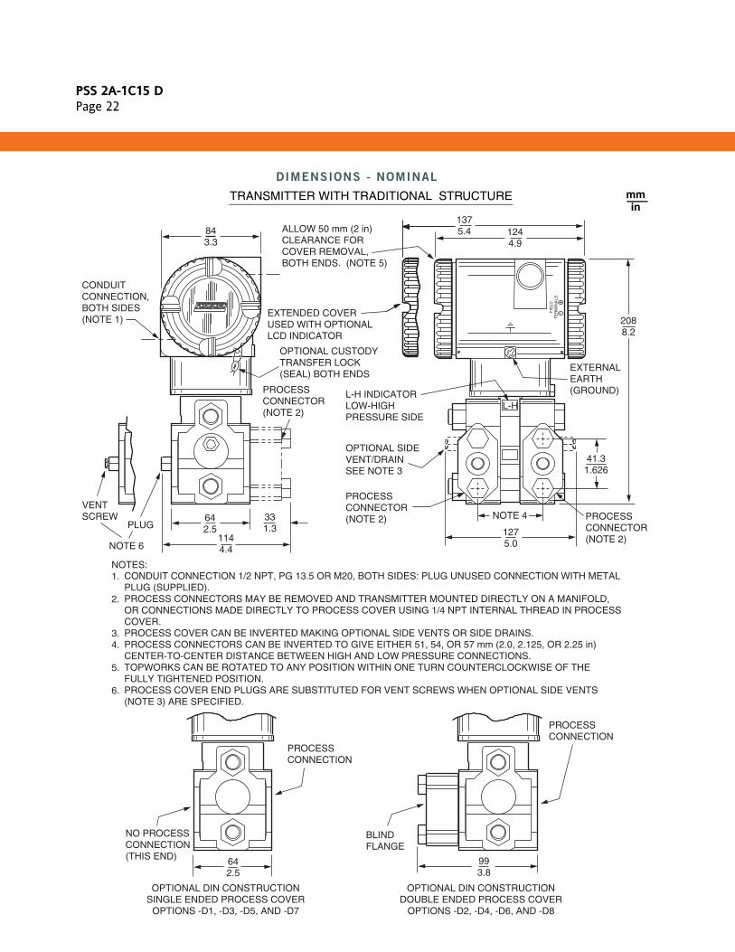
DIMENSIONS - NOMINAL
CONDUITCONNECTION,BOTH SIDES(NOTE 1)
VENTSCREW
PLUG
NOTE 6
OPTIONAL CUSTODYTRANSFER LOCK (SEAL) BOTH ENDS
PROCESS CONNECTOR (NOTE 2)
843.3
642.5
331.3
1144.4
1244.9
2088.2
41.31.626
1275.0
NOTE 4
ALLOW 50 mm (2 in)CLEARANCE FOR COVER REMOVAL,BOTH ENDS. (NOTE 5)
L-H INDICATORLOW-HIGHPRESSURE SIDE
OPTIONAL SIDEVENT/DRAINSEE NOTE 3
PROCESSCONNECTOR(NOTE 2)
EXTERNALEARTH(GROUND)
PROCESSCONNECTOR(NOTE 2)
L-H
CONDUIT CONNECTION 1/2 NPT, PG 13.5 OR M20, BOTH SIDES: PLUG UNUSED CONNECTION WITH METALPLUG (SUPPLIED).PROCESS CONNECTORS MAY BE REMOVED AND TRANSMITTER MOUNTED DIRECTLY ON A MANIFOLD,OR CONNECTIONS MADE DIRECTLY TO PROCESS COVER USING 1/4 NPT INTERNAL THREAD IN PROCESSCOVER.PROCESS COVER CAN BE INVERTED MAKING OPTIONAL SIDE VENTS OR SIDE DRAINS.PROCESS CONNECTORS CAN BE INVERTED TO GIVE EITHER 51, 54, OR 57 mm (2.0, 2.125, OR 2.25 in)CENTER-TO-CENTER DISTANCE BETWEEN HIGH AND LOW PRESSURE CONNECTIONS.TOPWORKS CAN BE ROTATED TO ANY POSITION WITHIN ONE TURN COUNTERCLOCKWISE OF THEFULLY TIGHTENED POSITION.PROCESS COVER END PLUGS ARE SUBSTITUTED FOR VENT SCREWS WHEN OPTIONAL SIDE VENTS (NOTE 3) ARE SPECIFIED.
NOTES:1.
2.
3.4.
5.
6.
FIE
LDT
ER
MIN
ALS
993.8
BLIND FLANGE
PROCESSCONNECTION
EXTENDED COVERUSED WITH OPTIONALLCD INDICATOR
1375.4
642.5
NO PROCESSCONNECTION(THIS END)
PROCESSCONNECTION
mmin
TRANSMITTER WITH TRADITIONAL STRUCTURE
OPTIONAL DIN CONSTRUCTIONDOUBLE ENDED PROCESS COVER
OPTIONS -D2, -D4, -D6, AND -D8
OPTIONAL DIN CONSTRUCTIONSINGLE ENDED PROCESS COVER
OPTIONS -D1, -D3, -D5, AND -D7

PSS 2A-1C15 DPage 23
DIMENSIONS - NOMINAL (CONT.)
mmin
TRANSMITTER WITH LOW PROFILE STRUCTURE LP1
CONDUITCONNECTION,BOTH SIDES(NOTE 1)
OPTIONAL CUSTODYTRANSFER LOCK (SEAL) BOTH ENDS
843.3
41.31.626
863.4
1244.9
2218.7
ALLOW 50 mm (2 in)CLEARANCE FOR COVER REMOVAL,BOTH ENDS. (NOTE 5)
STANDARDVENT/DRAIN,SEE NOTE 3.
PROCESSCONNECTOR(NOTE 2)
EXTERNALEARTH(GROUND)
CONDUIT CONNECTION 1/2 NPT, PG 13.5, OR M 20, BOTH SIDES: PLUG UNUSED CONNECTION WITH METALPLUG (SUPPLIED).PROCESS CONNECTORS MAY BE REMOVED AND TRANSMITTER MOUNTED DIRECTLY ON A MANIFOLD, ORCONNECTIONS MADE DIRECTLY TO PROCESS COVER USING 1/4 NPT INTERNAL THREAD IN PROCESS COVER.THE TRANSMITTER'S LOW PROFILE STRUCTURE LP1 IS SHOWN IN THE VERTICALLY UPRIGHT POSITION.NOTE THE LOCATION OF THE STANDARD VENT/DRAIN SCREW. IN THIS CONFIGURATION THE TRANSMITTERCAN BE VENTED OR IS SELF-DRAINING. ALSO RECOMMENDED IS A HORIZONTAL INSTALLATION WHERE THEINSTALLED ORIENTATION CAN BE SET TO ALLOW FOR VENTING OR DRAINING. PROCESS CONNECTORS CAN BE INVERTED TO GIVE EITHER 51, 54, OR 57 mm (2.0, 2.125, OR 2.25 in)CENTER-TO-CENTER DISTANCE BETWEEN HIGH AND LOW PRESSURE CONNECTIONS.TOPWORKS CAN BE ROTATED TO ANY POSITION WITHIN ONE TURN COUNTERCLOCKWISE OF THEFULLY TIGHTENED POSITION.
NOTES:1.
2.
3.
4.
5.
FIE
LDT
ER
MIN
ALS
EXTENDED COVER USED WITH OPTIONALLCD INDICATOR
1375.4
NOTE 4
1887.4
L-H

PSS 2A-1C15 DPage 24
DIMENSIONS - NOMINAL (CONT.)
mmin
TRANSMITTER WITH LOW PROFILE STRUCTURE LP2
CONDUITCONNECTION,BOTH SIDES(NOTE 1)
OPTIONAL CUSTODYTRANSFER LOCK (SEAL) BOTH ENDS
843.3
41.31.626
993.9
1244.9
2218.7
ALLOW 50 mm (2 in)CLEARANCE FOR COVER REMOVAL,BOTH ENDS. (NOTE 5)
STANDARDVENT/DRAIN,SEE NOTE 3.
PROCESSCONNECTOR(NOTE 2)
EXTERNALEARTH(GROUND)
CONDUIT CONNECTION 1/2 NPT, PG 13.5, OR M 20, BOTH SIDES: PLUG UNUSED CONNECTION WITH METALPLUG (SUPPLIED).PROCESS CONNECTORS MAY BE REMOVED AND TRANSMITTER MOUNTED DIRECTLY ON A MANIFOLD, OR CONNECTIONS MADE DIRECTLY TO PROCESS COVER USING 1/4 NPT INTERNAL THREAD IN PROCESS COVER.THE TRANSMITTER'S LOW PROFILE STRUCTURE LP2 IS SHOWN IN THE RECOMMENDED VERTICAL UPRIGHT POSITION. NOTE THE STANDARD VENT OR DRAIN SCREWS. HORIZONTAL INSTALLATIONS ARE NOT RECOMMENDED.PROCESS CONNECTORS CAN BE INVERTED TO GIVE EITHER 51, 54, OR 57 mm (2.0, 2.125, OR 2.25 in)CENTER-TO-CENTER DISTANCE BETWEEN HIGH AND LOW PRESSURE CONNECTIONS.TOPWORKS CAN BE ROTATED TO ANY POSITION WITHIN ONE TURN COUNTERCLOCKWISE OF THEFULLY TIGHTENED POSITION.
NOTES:1.
2.
3.
4.
5.
FIE
LDT
ER
MIN
ALS
EXTENDED COVERUSED WITH OPTIONALLCD INDICATOR
1375.4
1606.3
NOTE 4
1887.4
L-H

PSS 2A-1C15 DPage 25
DIMENSIONS - NOMINAL (CONT.)
NOTERefer to Dimensional Print DP 020-432 for further information.
mmin
TRANSMITTER WITH STANDARD STYLE MOUNTING BRACKET KIT (Options -M1 and -M2)
34513.6
993.9
281.1
2038.0FOR SURFACE MOUNTING, REPLACE
U-BOLT WITH TWO 0.375 in DIAMETERBOLTS OF SUFFICIENT LENGTH TO PASSTRROUGH BRACKET AND SURFACE.
VERTICAL PIPE
HORIZONTAL PIPE
VERTICAL PIPE
TRANSMITTERWITH
TRADITIONALSTRUCTURE
TRANSMITTERWITH
LOW PROFILESTRUCTURE LP2
32512.8
PSS 2A-1C15 DPage 26
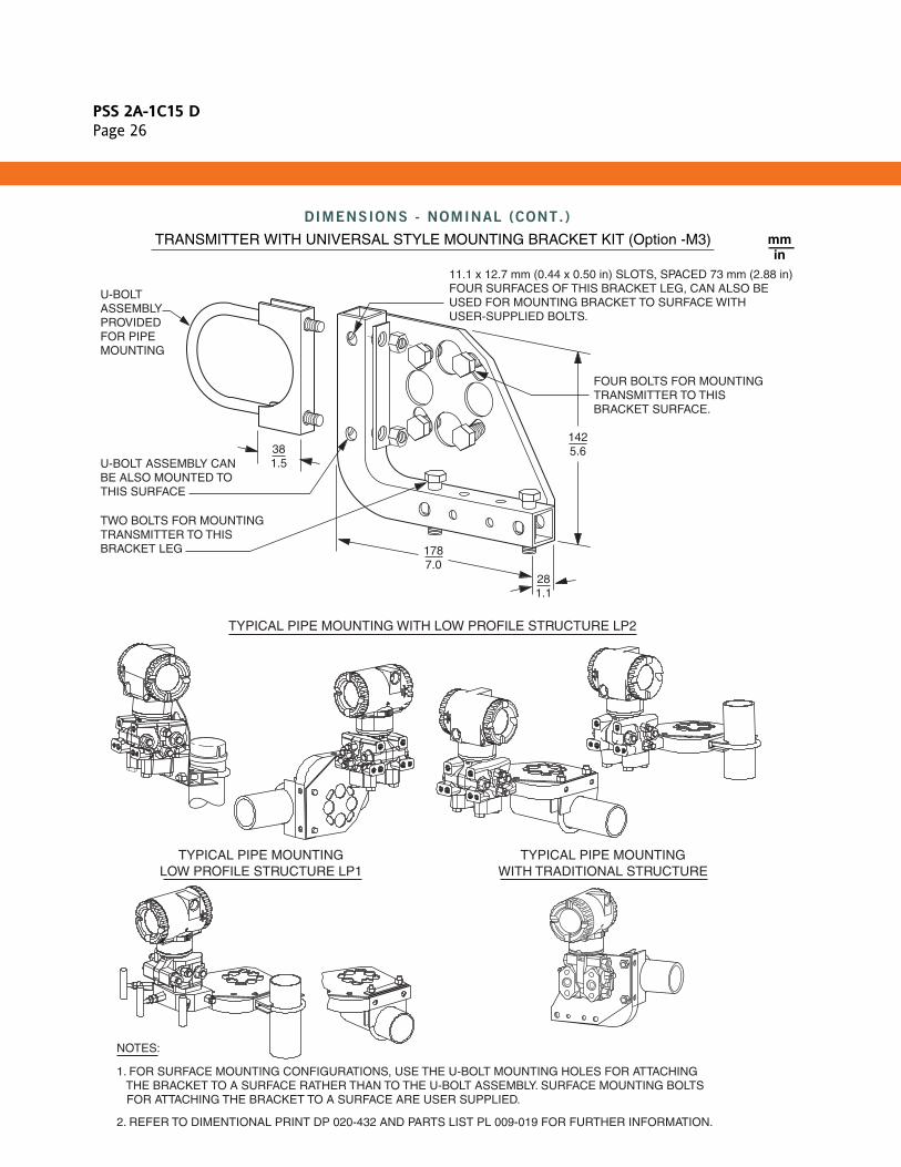
DIMENSIONS - NOMINAL (CONT.)
mmin
TRANSMITTER WITH UNIVERSAL STYLE MOUNTING BRACKET KIT (Option -M3)
NOTES:
U-BOLT ASSEMBLYPROVIDED FOR PIPE MOUNTING
U-BOLT ASSEMBLY CAN BE ALSO MOUNTED TO THIS SURFACE
TWO BOLTS FOR MOUNTINGTRANSMITTER TO THISBRACKET LEG
11.1 x 12.7 mm (0.44 x 0.50 in) SLOTS, SPACED 73 mm (2.88 in) FOUR SURFACES OF THIS BRACKET LEG, CAN ALSO BE USED FOR MOUNTING BRACKET TO SURFACE WITH USER-SUPPLIED BOLTS.
FOUR BOLTS FOR MOUNTINGTRANSMITTER TO THIS BRACKET SURFACE.
1425.6
1787.0
281.1
381.5
TYPICAL PIPE MOUNTING WITH LOW PROFILE STRUCTURE LP2
TYPICAL PIPE MOUNTINGLOW PROFILE STRUCTURE LP1
TYPICAL PIPE MOUNTINGWITH TRADITIONAL STRUCTURE
1. FOR SURFACE MOUNTING CONFIGURATIONS, USE THE U-BOLT MOUNTING HOLES FOR ATTACHING THE BRACKET TO A SURFACE RATHER THAN TO THE U-BOLT ASSEMBLY. SURFACE MOUNTING BOLTS FOR ATTACHING THE BRACKET TO A SURFACE ARE USER SUPPLIED.
2. REFER TO DIMENTIONAL PRINT DP 020-432 AND PARTS LIST PL 009-019 FOR FURTHER INFORMATION.

PSS 2A-1C15 DPage 27

PSS 2A-1C15 DPage 28
ORDERING INSTRUCTIONS
OTHER M&I PRODUCTS
1. Model Number.
2. Calibrated Pressure Ranges for both DP and AP using allowable pressure units from the table below.
3. Optional Features and Accessories not Included in Model Code (See PSS 2A-1Z9 E).
4. User Tag Data - Data Plate; 32 characters maximum. For additional tag data, specify Optional Supplemental Tag -T.
5. User Tag Data - Software (Database); 8 characters maximum (user configured).
inH2O psi kPa mbar kg/cm2 cmHg
ftH2O atm mPa bar inHg cmH2O
mmH2O Pa torr g/cm2 mmHg inH2O
(a) For Absolute Pressure, the letter “a” is added to each of the pressure units (e.g. kPaa) and can be displayed on the optional LCD Indicator.
Foxboro provides a broad range of measurement and instrument products, including solutions for pressure, flow, analytical, positioners, temperature, controlling and recording. For a listing of these offerings, visit the Foxboro web site at:
www.ips.invensys.com
IPS Corporate Headquarters5601 Granite Parkway Suite 1000Plano, TX 75024www.ips.invensys.com
Foxboro Global Client SupportInside U.S.: 1-866-746-6477Outside U.S.: 1-508-549-2424 or contact your local Foxboro representative.Facsimile: 1-508-549-4999
Invensys, Foxboro, I/A Series, and IPS Logo are trademarks of Invensys plc, its subsidiaries, and affiliates.All other brand names may be trademarks of their respective owners.
Copyright 2004-2009 Invensys Systems, Inc.All rights reserved
MB 010 Printed in U.S.A. 1009