public works department street light design policy manual …
TRANSCRIPT

CITY OF OCEANSIDE
PUBLIC WORKS DEPARTMENT
STREET LIGHT DESIGN
POLICY MANUAL
FOR NEW STREET LIGHT INSTALLATIONS
Modified for LED
8/12/2021

City of Oceanside
STREET LIGHT DESIGN POLICY MANUAL
FORWARD
This manual establishes uniform policies and procedures for the
preparation of street lighting plans in the City of Oceanside. It is
not intended as a textbook, or a substitute for engineering
knowledge, experience, or judgment, but rather as a guideline to
uniformity and to provide the designer with sufficient information
to prepare the desired plans.
Street lights installed in the City’s downtown area, El Corazon
area, and in the Rancho Del Oro area may have special design
specifications. Engineer should check with the Public Works
Department, Transportation Division and Planning Division before
starting project.

City of Oceanside
STREET LIGHT DESIGN POLICY MANUAL
I. GENERAL REQUIREMENTS
The Engineer preparing street lighting design shall:
A. Utilize latest National Electrical Codes, The City of Oceanside Guidelines,
The State of California Department of Transportation Standard Specs, and
The San Diego Regional Standard Drawings. B. Include the City’s special design requirements as defined in Section III of this
manual. C. Pothole locations of the proposed poles prior to completion of the plans (if
conflicts are foreseen). D. Utilize City of Oceanside standard plan sheets and title sheets. Plans shall
be signed by a registered civil engineer or an electrical engineer. E. Meet with City Traffic Division to review design concepts drawing for
discussion. F. Coordinate with the serving utility company for service points and conflicts. G. Send plans to all utility companies for their information. H. Provide three sets of check prints at each submittal. I. For street lighting standard, refer to San Diego Regional Standard Drawing
No. E-1 (Anchor Base Foundation, reference Exhibit C and D). J. Street lights shall be LED type.
K. Street lights shall be anchor base foundation (no direct burial foundation).
L. For street light location refer to the City of Oceanside Engineers Manual,
Drawing Number M-4. M. Street light spacing and luminaire shall be in conformance with Table A
(Street Design Criteria) of the City of Oceanside Engineers Manual. N. Street lights shall normally be located on the outside of curves. Lights shall be
located behind sidewalk (approximately six feet) when curb and sidewalk are
contiguous, or thirty-six inches on center from the face of the curb when
sidewalk is not contiguous.
O. The street lighting plan shall include a two-inch PVC conduit with a #10 green
trace wire on the frontage of a project on all arterials and above for future
fiber optic cable. No. 6 Pull boxes shall be installed every four-hundred feet.
1
City of Oceanside
STREET LIGHT DESIGN POLICY MANUAL
II. PLAN FORMAT AND DRAFTING REQUIREMENTS
A. The City requires that all street lighting plans be prepared on Mylar. The
quality of drafting and lettering size shall be able to produce clear,
concise, and legible reproductions in order to insure legible reduced prints.
Plans shall be produced in AutoCAD. A copy of the electronic file of the
signed drawings shall be submitted to the City, along with the pen table
used to plot the drawing. Files shall be provided in both .PDF and .DWG
formats.
B. Plans should include street light location and detail, conduit runs, pull box
locations, service point locations, and transformer locations.
C. Plan preparation shall conform to and/or include the following
requirements:
1. North shall always be oriented up or to the right on all plans. The
major arterial shall always be horizontal on the plan.
2. Street lighting plans shall be drawn from 1” = 40’ to 1” = 100’ scale
on 24” X 36” City of Oceanside Mylar sheets.
D. Any deviation from the various formats shown on the typical plan shall be approved by the City prior to implementation. E. SDG&E requires a “Street Light” only sheet. No other improvements shall be on that sheet.
III. SPECIAL DESIGN REQUIREMENTS
The following items provide further information about special requirements of the City of Oceanside:
A. Street lights installed in the City’s downtown area, Rancho Del Oro
area, and El Corazon Specific Plan may have special design
specifications.
1) Rancho Del Oro street lights on residential streets shall be a square
bronze concrete direct burial pole (Ameron MEQ 7.5 w/Armorshield
or equivalent), bronze arm, bronze GE LED light fixture (39w), and
GE communication node.
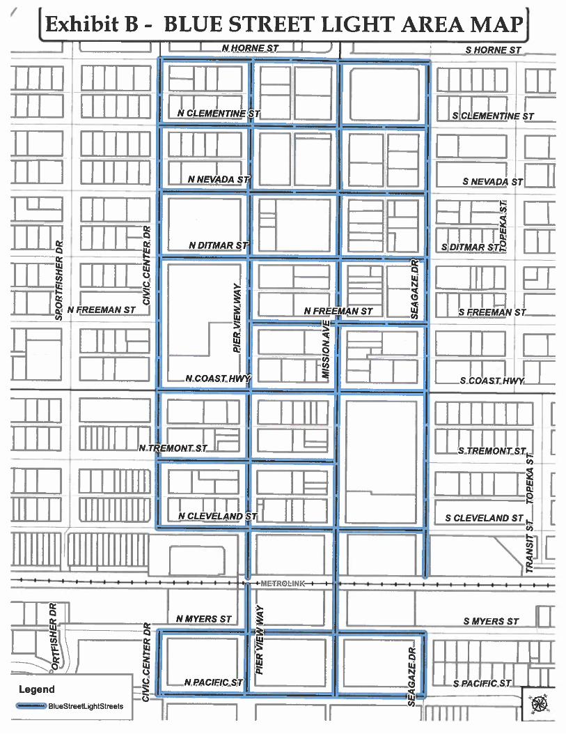
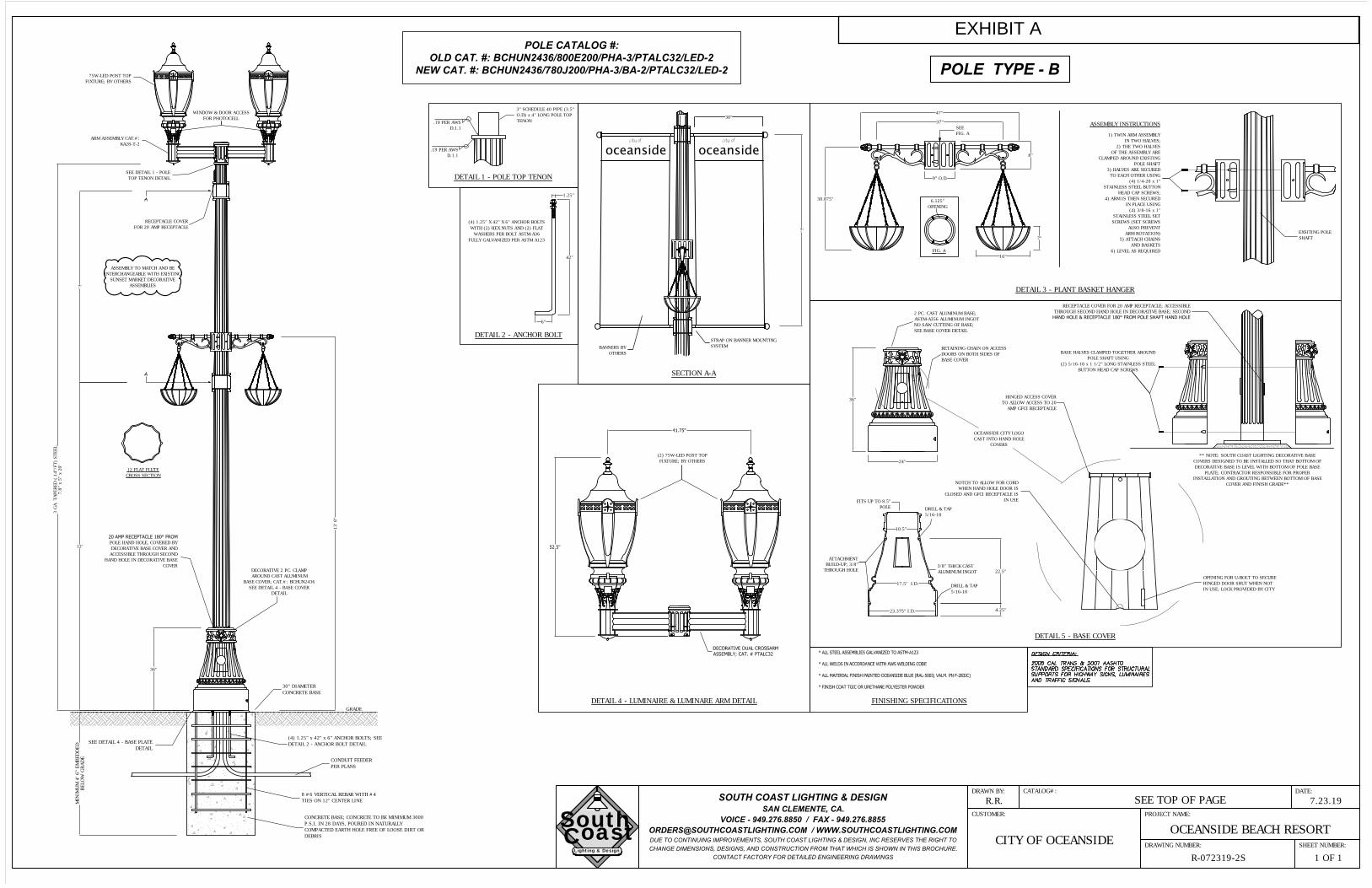
2) City’s downtown area shall have City of Oceanside blue decorative
blue poles with crossarm that can hold 2 decorative LED light
fixtures (GE Avery fixture with Type 3 and 5 light distribution with
GE Communication Nodes). Pole shall have a decorative skirt/ with
City seal and plant hanger. If receptacles are to be installed on the
poles, a meter/unmetered Type III service pedestal shall be
installed. Receptacles installed in the pole will have one at the top
and one at the bottom (GFCI at bottom) (See Exhibit “A”). 2

City of Oceanside
STREET LIGHT DESIGN POLICY MANUAL
Street lights shall be on both sides of the streets and a minimum of
36 inches from center of the pole to the face of curb and. Refer to
map of downtown (See Exhibit “B”) for boundaries.
3) El Corazon Specific Plan lights shall be Bega Lighting model 77910
or 77911 (Platinum Grey) with 14- foot or 17-foot with aluminum
poles (Platinum Grey). Refer to El Corazon Specific Plan for more
details.
4) Engineer should check with the Public Works Department and
Development Services Department Engineering Division before
starting project.
IV. MATERIALS A. General
All street lights west of Interstate 5 shall have the “coastal finish”. Street
lighting luminaire descriptions shall be as follows:
Application: 1. Local/Two Lane Collector
a. Use: 50’ or less, curb to curb
b. Minimum Lumens: 4,000
c. Color Temperature: 3000K
d. Distribution: Type II, Medium
e. Maximum Wattage: 39
2. Cul-de-Sac a. Use: Bulb within Cul-de-Sac b. Minimum Lumens: 4000 c. Color Temperature: 3000K
d. Distribution: Type III/IV Short
e. Maximum Wattage: 39
3. Two/Four Lane Collector, High Output a. Use: As determined by City Engineer b. Minimum Lumens, 6,500 c. Color Temperature: 3000K
d. Distribution: Type II, Medium
e. Maximum Wattage: 58
4. Major/Four Lane Collector-Midblock a. Use: Mid-block, more than 50’ curb to curb
b. Minimum Lumens: 10,000
c. Color Temperature: 4000K 3

City of Oceanside
STREET LIGHT DESIGN POLICY MANUAL
d. Distribution: Type III, Medium
e. Maximum Wattage: 98
5. Major/Four Lane Collector-Intersection a. Use: Intersection, more than 50’ curb to curb b. Minimum Lumens: 10,000 c. Color Temperature: 4000K
d. Distribution: Type III/IV, Medium
e. Maximum Wattage: 98
Luminaire Products: 1. Local/Two Lane Collector:
a. General Electric: ERL1-0-05-B3-30-A-GRAY-L
2. Cul-de-Sac: a. General Electric: ERL1-0-05-D3-30-A-GRAY-L
3. Two/Four Lane Collector, High Output: a. General Electric: ERL1-0-07-B3-30-A-GRAY-L
4. Major/Four Lane Collector-Mid-Block: a. General Electric: ERLH-0-11-B3-40-A-GRAY-L
5. Major/Four Lane Collector-Intersection: a. General Electric: ERLH—0-11-D3-40-A-GRAY-L
Control Products:
1.Adaptive Control Node: a. General Electric: ELWN0A5UG5-OSIDE
General: 1. Luminaire mounting height: 30 feet for Major/Four Lane Collector and
27 feet for Local/Two Lane Collector. 2. Mast arm: 8-feet with a 1-foot minimum overhang past face of curb
3. Pole: Round tapered concrete anchored base, with flared base;
Ameron 2B2-26 or equivalent for Major/Four Lane Collector and
Ameron 2B2-24 or equivalent, for Local/Two Lane Collector.
4

City of Oceanside
STREET LIGHT DESIGN POLICY MANUAL
B. Luminaires
General Requirements
1. Each luminaire shall consist of an assembly that utilizes light emitting
diodes (LEDs) as the light source.
2. The LEDs used in the luminaire shall be manufactured by Cree, Nichia
or Philips.
3. The individual LEDs shall be connected such that a catastrophic loss
or the failure of one LED will not result in the loss of the entire
luminaire. For luminaires constructed with sub-arrays or bars, the loss
of one sub-array will not result in the loss of functions of the remaining
arrays.
4. The luminaires shall be designed to operate at an average nighttime
temperature of 70F (21C). The nominal ambient operating
temperature range shall be -20°C to +40°C.
5. The luminaire assembly shall be rated for a minimum life of fifty-
thousand (50,000) hours at an ambient temperature of 25°C. The L85
Reported Lifetime shall exceed 50,000 hours. The L70 Reported
Lifetime shall exceed 100,000 hours. These values shall be reported
per IES LM-79 & 80 and IES TM-21 standards and procedures.
6. LED fixtures shall offer an option to be upgradeable to include
necessary components for interface to adaptive lighting, diagnostic
and/or individual energy usage metering systems. 7. All luminaires must be pre-qualified and listed on the Design Lights
Consortium Qualified Products List (DLCQPL) prior to time of bid.
8. All components of the luminaire shall be RoHS compliant.
Electrical Requirements
1. Nominal Operating Voltage: The luminaire shall operate at 120V or
240V depending on location. The luminaire shall operate correctly over
a voltage range from 95 VAC to 305 VAC. Fluctuations of line voltage
within this range shall have no visible effect on the luminous output.
2. Power Factor: Power supply should have a minimum Power Factor of
.90.
3. Maximum allowed Amperage at LED (Drive current): 1100mA 4. Total harmonic distortion shall not exceed 20%. 5. Surge suppression: The luminaire on-board circuitry shall include
surge suppression devices (SPD) to withstand high repetition noise
transients as a result of utility line switching, lighting strikes and other 5

City of Oceanside
STREET LIGHT DESIGN POLICY MANUAL
interference. SPD shall conform to IEEE/ANSI C62.41.2-2002 and UL
1449 or UL 1283, depending of the components used in the design.
SPD shall be three wire.
6. Interference: Power supplies shall meet FCC 47 CFR Part 15, Class
A.
7. Each luminaire shall have an ANSI C136.41-2013, 7-conductor, twist-
lock, photocell receptacle.
8. Field wires connected to the luminaire shall terminate on a barrier type
terminal block secured to the housing. The terminal screws shall be
captive and equipped with wire grips for conductors up to #6 AWG.
Each terminal position shall be clearly identified.
9. LED driver shall have quick disconnects on both line and output leads.
Optical Requirements
1. Maximum Correlated Color Temperature (CCT): a. 3000K for Local and Local Collector Streets b. 4000K for Major and Four Lane Collector streets
2. Color Rendering Index (CRI): Luminaires shall have a minimum CRI of 70.
3. Upward Component of IES TM-15-11 BUG rating shall be U0. (Formerly referred to as ‘Full Cutoff’).
4. Shall have a standard, factory provided option for a field installed,
house side shield.
Cooling System
1. Thermal management of the heat generated by the LEDs shall be of
sufficient capacity to assure proper operation of the luminaire over the
expected useful life. 2. Thermal management shall be passive by design and shall consist of a
heat sink with no moving mechanical parts or liquids.
Physical / Mechanical Requirements
1. The luminaire shall be a single, self-contained device, not requiring on-
site assembly for installation. The power supply for the luminaire shall
be integral to the unit. 2. Weight: Luminaire shall not weigh more than forty (40) pounds. 3. Maximum dimensions: 40-inches long x 16-inches wide by 7-inches tall.
6
City of Oceanside
STREET LIGHT DESIGN POLICY MANUAL
4. Housing shall be completely constructed of metal, except for gaskets,
lenses, etc. Housing finish shall be gray in color and powder coated.
LED mounting plates shall be constructed and finished as required for
proper operation by each manufacturer.
5. Luminaire shall be warranted rust proof for the warranty period. 6. All components must be fully accessible for servicing without removing
the luminaire from its mounting. 7. Access doors and panels shall be hinged and accessible without tools.
Door shall be captive and shall require an extra motion, i.e.: swing 90
deg past vertical, lift upward, etc. to remove. If not, provide clips or
lanyard to prevent from falling when open.
8. All hardware and fasteners shall be stainless steel or zinc-nickel
plated.
9. No parts shall be constructed of polycarbonate unless required by
optics, i.e.: a lens. If required, it shall be UV stabilized (lens
discoloration shall be considered a failure under warranty).
10. Mounting Arm Connection: Luminaires shall mount on min 1-5/8 inches OD to max 2-3/8 inches OD horizontal tenon with no more than four (4) 9/16 inches hex bolts and no more than two-two bolt clamps.
11. Luminaire leveling capability shall be integral to the fixture with exterior leveling ribs in both directions or interior bubble level.
12. The assembly and manufacturing process for the LED luminaire shall
be designed to assure all internal components are adequately
supported to withstand mechanical shock and vibration from wind
loads up to 100 MPH.
13. Ingress Protection Ratings: Optical chamber shall be IP66 rated.
Wiring compartment shall be UL Wet Location listed.
14. Circuit boards shall conform to Chapter 1, Section 6 of the
“Transportation Electrical Equipment Specifications” (TEES).
15. Powder coating of the housing shall conform to the requirements of the
Caltrans Standard Specification and the Caltrans Standard Special
Provisions. In addition, it shall exceed a rating of six per ASTM D1654
after 1000 hours of testing per ASTM B117.
16. Environmental Impact: Must be free of lead and mercury. Must be
modular in design and recyclable.
17. Wildlife Shield: Luminaire shall have a wildlife shield, either as a
separate piece or cast into the housing.
7

City of Oceanside
STREET LIGHT DESIGN POLICY MANUAL
Luminaire Identification
1. Each luminaire shall have the manufacturer’s name, trademark, model
number, serial number, date of manufacture (month and year) with lot
number and replacement part numbers permanently marked inside
each unit and the outside of each packaging box.
2. The following operating characteristics shall be permanently marked
inside each unit: rated voltage and rated power in Watts and Volt-
Ampere, CCT rating in Kelvin and Luminaire Efficiency Rating (LER).
3. Luminaire shall have an exterior wattage label that indicates the
wattage for the selected drive current. Label shall be easily read from
the ground.
Quality Assurance
1. Luminaires shall be manufactured in accordance with ISO9001.
Warranty
1. Manufacturers shall provide a written warranty for full replacement of the
luminaire due to any failure for a period of ten (10) years from the date of
installation.
2. Luminaires shall, at the city’s option, be repaired or replaced if the
luminaire fails to function as described in the above specification for the
duration of the warranty period.
3. The written replacement warranty shall be converted to a written ON-
SITE replacement warranty if the field observed and documented
failure exceeds 5 percent for any installation of 100 or more identical
Components. On-site warranty replacement includes removal and
disposal of failed Components, along with delivery and installation of
new Components.
Measurement / Performance / Safety Standards
1. ANSI C78.377.2008: Specifications for the Chromaticity of Solid State Lighting Products.
2. IES LM-79-08: IESNA Approved Method for the Electrical and Photometric Measurements of Solid-State Lighting Products.
3. IES LM-80-08: IESNA Approved Method for Measuring Lumen Maintenance of LED Lighting Sources.
4. IES TM-21-11: Projecting Long Term Lumen Maintenance of LED Light Sources.
5. UL Listing: Listed for use in Wet Locations by NRTL 8

City of Oceanside
STREET LIGHT DESIGN POLICY MANUAL
C. Adaptive Controls Node General.
1. The adaptive control node (controller) shall consist of an assembly with the following features and requirements:
Control System Interface:
1. The controller shall transmit to the system the following values on a system of at least 250,000 controllers:
a. Voltage RMS b. Current RMS c. Power Factor d. Wattage e. Temperature f. Physical Location g. Controller Local Time GMT h. Network Address i. Network Parent j. RF Signal Strength k. Total Hours Controller l. Total Hours Load m. Active Schedule n. Next Scheduled Event Time o. Current Firmware Version p. Firmware Upload Version
2. The system shall support load identification via searchable fields that include:
a. Physical address b. Unique Billing Identification Number c. Pole Material Type d. Load Wattage e. Installation Date f. Pole Number
3. The system shall support SMTP or SMS user notifications for all measurement value reported outside of user defined limits.
4. All measurement data will be automatically stored in the CMS data base at a user defined interval of 15 minutes to 24 hours. 5. The System CMS shall be hosted by the customer or at his
specified hosting partner location. 6. The Gateways shall support both cabled (copper or fiber) and
wireless backhaul connectivity (cellular or equivalent).
9

City of Oceanside
STREET LIGHT DESIGN POLICY MANUAL
Asset Management:
1. All System controllers shall be equipped with an internal GPS receiver.
2. GPS location reporting error will in all cases be less than 3 meters when satellite signals are not obstructed.
3. All system components will automatically register and be displayed in the MAP view of the deployment area.
4. A total of all Controllers registered will be prominently displayed on the MAP view of the Graphic user interface.
5. A total of all Controllers in the error state will be prominently displayed on the MAP view of the Graphic user interface.
Energy Metering and Billing Data Transfer:
1. All controllers shall contain a subsystem the complies to ANSI 12.20- 0.5% Metering Accuracy Class.
2. The controller shall in all cases report the combined total of all energy consumed by both the controller and the load.
3. Energy metering shall start within 3 seconds of power being applied to the controller.
4. Power outage recovery events shall not result in more than 3 seconds of unmetered energy consumption.
5. The system shall export energy consumption for each controller at a minimum of once every 24 hours.
6. The system shall report the total energy consumption in 15 minute intervals that shall end on the 1/4 hour GMT (IE 00:15:30:45).
7. All Data shall be formatted and transferred in accordance to: ANSI- X12 formatting criteria and Transaction Set 867 Ver/Rel 004010, meter Interval and Historical Usage Reporting Version 1.1 • Jul 16, 2006.
Wireless Mesh:
1. The Wireless Lighting Control system shall: a. Utilize license free 915 MHz spectrum. b. In all cases provide a wireless connection to all other
controllers or gateways within 500 meters free from obstacles.
c. Transmit using a randomly selected channel from a group of a minimum of 50 discrete channels to minimize interference.
d. Comply with all IEEE 802.154g PHY communication standard requirements.
e. Comply with all IETF 6LoWPAN communication standard requirements.
10

City of Oceanside
STREET LIGHT DESIGN POLICY MANUAL
f. Utilize a self-forming and self-restoring mesh communications protocol.
Security:
1. All System Components will be assigned a unique permanent serial number by the manufacture (MAC ADDRESS).
2. All System Components will only use a system wide unique IPV6 address reference, no dynamic address schemes.
3. All Wireless Connections will utilize a unique 128-bit ECC encryption key 256-bit Certificate Authority registered authentication key.
4. All Wired Connections will utilize a unique 256-bit encryption key and a 256 bit Certificate Authority registered authentication key.
5. All encryption & authentication keys will be wirelessly revocable & updateable by the user should they be compromised.
Dimming (Power Trimming):
1. All controllers shall continuously adjust the load consumption within 2% of the user defined target over the full temperature range.
2. All controllers shall utilize a power change ramp rate of 1 second per 1% of total load wattage change.
3. All controllers shall support Lumen Maintenance and Constant light
output over the life of the load (default is LM70).
Mechanical:
1. All controller and gateway electronic components and printed circuit boards shall be conformal coated.
2. The controller housing will be rated IP54 and allow any moisture to drain without effecting operation.
3. The Gateway housing will be rated IP66 and allow any moisture to drain without effecting operation.
4. The total power consumption for the gateway shall not exceed 3W @120-240 VAC.
5. The total power consumption for the controllers shall not exceed 2W @120-240 VAC.
6. Controllers shall be integrated (mechanically and electrically connected) at Control Points External to Luminaires, using a NEMA C136.41 standard polarized twist-lock receptacle or equivalent for both electrical and dimming control signal connectivity.
7. The rated life of all Field Devices shall be 15 years or more at an ambient temperature of 25 degrees Celsius.
8. All controllers shall be UL listed.
11

City of Oceanside
STREET LIGHT DESIGN POLICY MANUAL
Warranty:
1. All Field devices shall be covered by a single-source written replacement warranty covering material and workmanship for a period of TEN (10) years.
2. All software and firmware shall be covered by a written replacement warranty covering material and workmanship for a period of TWO (2) years.
D. Fuses
Fuses shall be 13/32-inches x 1 ½-inches in line twenty (20) amps at service point and ten (10) amps at pole. The fuse shall be installed in the hot leg of the lighting conductor. The circuit shall be fused in the base of the pole, not in a pull box. Fuse holders shall not go on white neutral wires.
E. Fuseholders
Fuse holders shall be completely waterproof, shall grip the fuse in load
side section when fuse holder is opened, be able to take an 13/32-
inches x 1½-inches fuse, rated at thirty amperes at 600 volts or less,
with crimp type tubular terminals of a size able to take the size cable in
the particular street light. The fuse holder shall be located in the access
hole of the street light pole. Conductors larger than #8 shall have the
same size fuse holder.
F. Wiring
Wiring circuits, including poles, shall be three wire system and contain the following:
1. White-neutral
2. Black only-ungrounded conductor
3. Green-ground
All wire shall be stranded cooper wire No. 10 AWG (THWN/THHN)
minimum. Copper wire shall conform to the applicable portion of ASTM
B3 and B8. Size of wire used shall be indicated on the plans. Wire
connectors shall be of type approved by the Engineer and shall be UL
listed. The installation procedure, including connector size and
crimping tools shall conform to the manufacturer’s recommendations.
Aluminum conductors shall not be substituted for copper. All plans will
be checked for voltage drop at plan check and calcs shall be
12
City of Oceanside
STREET LIGHT DESIGN POLICY MANUAL
submitted. If voltage drop is excessive, plans will be rejected with
suggested modifications. Voltage drop not to exceed three percent
without approval of the City Engineer. (Maximum seven lights per
circuit).
Receptacles in downtown decorative blue poles shall be GFCI
protected with the bottom receptacle being the GFCI. Exposed boxes
shall be rated for outdoors and the covers shall be “in use” covers.
Boxes shall be “City of Oceanside Blue” to match pole. Receptacles in
the pole shall use: Red (ungrounded conductor) and its own
designated white (neutral). The receptacles can share the green
(ground) wire with the lighting. These receptacles shall come from a
metered source. They shall not be fed from the street lighting circuit.
G. Grounding
A 5/8-inches x 8-foot ground rod shall be installed in city pull box next to the SDG&E service point. All ground wires will be connected to the ground rod. 15-feet of #4 stranded copper wire will be coiled and lay firmly at bottom of street light base with one inch of coverage of dirt. Bond #4 copper ground wire to one anchor bolt with ground clamp. All green grounds and Ufer grounds shall be bonded together and to street light pole.
H. Splicing
Splices shall be permitted in pull boxes and lighting standard bases
only. All splices shall be waterproof, by using splice kits (3M bags or
equal, #4 conductors or larger heat shrinking is allowed) listed for the
purpose. Silicone filled wire nuts shall not be used.
I. Conduit
All conduits shall be minimum two inch UL approved heavy wall
polyvinyl chloride (PVC Sch-40). Conduit shall be sand encased (three
inches minimum over conduit and all sided). The Contractor may, at
his expense, use conduit of a larger size, provided the larger size is
used for the entire length of the run. Reducing couplings shall not be
used. Conduit shall be laid to a depth of not less than thirty inches
below the curb grade in sidewalk areas and curbed paved median
areas, thirty inches below highway pavement grade in road areas and
finished grade in all other areas. Install “Electrical” burial tape
minimum of 6-inches above the conduit. Conduit laid in open trench shall not
13

City of Oceanside
STREET LIGHT DESIGN POLICY MANUAL
be covered nor shall any trench or inspection hole be backfilled until
installation has been accepted by the Engineer.
J. Pull Boxes
Pull boxes shall be “Christy” brand No. 3-1/2 Pull Box or equivalent
and shall be installed within five feet of each street lighting standard
and within five feet of each service point unless standard is within five
feet of service point. Pull boxes shall be spaced at not over two
hundred feet. The bottom of the pull box shall rest firmly on a twelve
inch thick bed of one-inch crushed rock extending six inches beyond
the outside edges of the pull box. Pull boxes shown in the vicinity of
curbs shall be placed adjacent to the back of the curb with non-
contiguous sidewalk and shall be adjacent to back of sidewalk with
contiguous sidewalk. Where practical, pull boxes shall not be installed
with the long side parallel to the curb. Pull boxes shall not be installed
in any part of a driveway or other traveled way unless approved by
Engineer. Concrete pull box covers shall be inscribed “STREET
LIGHTING.” Covers shall be secured with three-eighths inch bolts, cap
screws, or studs, and nuts which shall be of brass, stainless steel or
other non-corroding material. Pull boxes at service points shall have a
5/8-inch X 8-foot ground rod installed inside the pull box.
K. Concrete Pole Construction
Concrete poles shall be Ameron 2B2 (24-feet or 26-feet) series or equivalent,
tapered, centrifugally cast and pre-stressed. They shall be round, black
and white marble aggregate or natural exposed aggregate. The
ultimate strength of a pole shall be calculated in accordance with the
latest revision of American Concrete Institute (A.C.I.) Standard 318.
Under working loads (including wind loading) the pole must not be
stressed beyond the cracking strength. Wind loads shall be as
specified in the last edition of the AASHTO Standards. Pole shape and
color shall be uniform for any one project.
Aggregates shall conform to current requirements of ASTM C33,
except that abrasion requirements therein shall not apple and that no
more than seven percent shall pass a #100 mesh sieve. No dye or
sealer shall be used, without approval of the City Engineer. Mast arm
shall have one-foot minimum curb overhang.
14

City of Oceanside
STREET LIGHT DESIGN POLICY MANUAL
The centrifugal casting process shall produce a center duct throughout
the length of the pole. The duct shall be free from sharp projections or
edges which might injure the wire or cable. It shall have a minimum
cover of five-eighths inch diameter. After curing, the surface of the
standard shall be treated to remove cement laitance and develop the
surface texture.
When finished, poles shall be without cracks or crazing and shall have
a uniform surface (without objectionable mold marks) and texture
throughout the entire length. Maximum deviation from string line at any
point shall not exceed .03-inch per foot of length. Poles shall be
furnished with a mast arm that provides a minimum of six inches of
horizontal straight section at the end of the bracket arm to mount a two
inch I.P.S. slipfitter type luminaire. Handhole cover plate securing bolts
shall be stainless steel, not brass, plain steel, cadmium coated or
galvanized steel. Corrosion and subsequent freezing of these bolts is a
serious problem.
L. Anchor Bolts for Anchor Base Poles
Anchor bolts shall be of the type and size as shown on Regional
Standard Drawing E-1. Anchor bolts (1-inch x 36-inch x 4-inch minimum)
shall conform to the specifications of ASTM A 307, and shall be
provided with two nuts and two washers each.
Anchor bolts, nuts, and washers shall be fully galvanized by the hot-dip
process conforming to ASTM A 153, or cadmium plated with Type NS
coating conforming to ASTM A 165.
All nuts shall be symmetrically formed with the hole centered and at
right angles to the face, tapped to fit a corresponding thread so that
nuts can be run the entire length of the tread by the fingers without
undue forcing, and without noticeable play or rocking.
Plumbing of standards shall be accomplished by adjusting the nuts on
the anchor bolts before the foundation cap is placed. Shims or other
similar devices for plumbing or raking will not be permitted. After
plumbing, the standard anchor bolts shall be cut off one quarter inch
above the nuts and the exposed surfaces shall be required.
The contractor shall submit to the Engineer in conformance with the
above requirements and the Standard Specifications a certified list of
15

City of Oceanside
STREET LIGHT DESIGN POLICY MANUAL
all materials to be used for approval prior to installation. For Anchor
Base Foundation see Regional Standard Drawings E1 and E2.
Any dirt on footing/around anchors shall be removed prior to pouring
the concrete cap.
M. Mast Arms
Mast arms shall be two inch aluminum, self-supporting, without braces,
scrolls or rods. Mast arms shall be eight feet in length. Mounting shall
be perpendicular to street centerline unless otherwise shown on plans.
Aluminum arms shall be made of corrosion resistant alloys such as
Aluminum Association wrought alloys 6061 or 6062, or cast alloys 319
or 356.
Changes in configuration of mast arms will be permitted, providing the
mounting height and stability are maintained.
All exposed hardware shall be cadmium coated, hot dipped galvanized
or stainless steel. All protected hardware not visible after installation
shall be cast aluminum and/or stainless steel, hot dipped galvanized or
cadmium plated steel.
V. HOOK-UP TO SAN DIEGO GAS & ELECTRIC SERVICE POINT
To get a service point, contact SDG&E. They are the only ones that know
what is available and where it is. Sometimes a new light can be connected
to an existing light system, but that very seldom happens. The service
point should be in the City’s right-of-way, or you will need to give the City
an easement to the service point. SDG&E easement is not sufficient.
Easements are expensive and time-consuming to you. Avoid service runs
across private property if at all possible.
VI. WIRE AND CONDUIT TO SERVICE POINT
The lights shall be one hundred twenty volt in a one hundred twenty volt system, there must be a white neutral wire in addition to the black wire.
All ground wires will be green. All service points shall be consistent with
SDG&E. Service Guide. If the wire used is #8 or bigger or if it is a 3-wire
installation, two inch conduit will be used. Enough PVC conduit to reach
the rest of the way to the service point will be strapped to the pole.
SDG&E’s crew will install it. Enough wire to reach the service point will be
coiled up above the rigid conduit. If any of this is not done exactly this
16

City of Oceanside
STREET LIGHT DESIGN POLICY MANUAL
way, SDG&E. may turn down the job, which can cause costly delays to
your project. No more than two wires (Black & White Only) will be
allowed from streetlight service point pull box to SDG&E. transformer or
3312 secondary box.
Before SDG&E will energize the new street light(s), the City has to
approve the as-builts and the contractor will have to pay the 18-month
energy fee. Once the as-builts are approved and the fees have been
paid, the City will submit the as-builts, location detail, and the “Request to
Engergize” letter to SDG&E to allow them to schedule the new lights to
be energized.
VII. AS-BUILTS
Before SDG&E will hook-up light, two As-Built drawings on standard
24”X 36” City of Oceanside mylars must be given to your inspector.
SDG&E requires an electronic copy of the as-builts. They must clearly
show:
1. Pole Type and size 2. Wattage and type of each light. (for Example:98 watt LED) 3. Location of each light. 4. Conduit runs and pull boxes. 5. Service point. If the service point is a wooden pole, show the pole
number. 6. Size of wire. 7. Lengths and distances of wire runs.
As-Built drawings should be well-drawn and with as much detail as
possible, on Street Light print only. Sloppy and incomplete drawings will
be rejected. These drawings become part of the permanent file on this
development, and will be referred to in the future. Bonds will not be
released until As-builts are approved. As-built drawings shall be on 24” X
36” City of Oceanside mylars.
17
City of Oceanside
STREET LIGHT DESIGN POLICY MANUAL
VIII. OTHER NOTES
This is not a complete specification. It is a supplement to the Standard
Specifications for Public Works Construction, the Standard Special
Provision to Standard Specifications and the San Diego Regional
Standard Drawings. The term: Engineer, as used in these provisions, shall
mean the representatives from the City charged with the responsibility of
enforcing City Standards.
IX. STREET LIGHT INSPECTION CHECK LIST
Anchor Base Foundation 15’ #4 AWG Stranded Bare Ground at Pole Base (Ufer Ground) 1” of dirt on top of Coiled Ground Wire
Green Ground and Ufer Ground bonded together and to Pole
Round Tapered Concrete Pole
Pole Shape and Color Uniform to Project Mast Arm Overhanging Curb 1’ Minimum Cutoff Luminaire Adaptive Control Node in place and commissioned. #3.5 Pull Box every 200’ or less Pull Box within 5’ of Pole (Unless Pole within 10’ of S.P.) Pull Box within 5’ of Service (Unless Pole within 10’ of S.P.) Pull Box Resting on Crushed Rock Pull Box Inscribed “Street Lighting”
Non-Corrosive Bolts, Cap screws or Studs Secure Pull Box Covers
20 Amp Fuse in Service Pull Box
10 Amp Fuse in Pole behind Access Plate 13/32 X 1 ½ In-Line Waterproof Fuse Stranded #10 AWG (THWN) Minimum Splices only in Pull Box or Pole All Splices Waterproof using Splice Kits Conduit 2” Minimum PVC Schedule 40 Conduit Same Size throughout Project Stainless Steel Access Plate Screws
18
SEE DETAIL 1 - POLE
TOP TENON DETAIL
DECORATIVE 2 PC. CLAMP
AROUND CAST ALUMINUM
BASE COVER; CAT.#: BCHUN2436
SEE DETAIL 4 - BASE COVER
DETAIL
RECEPTACLE COVER
FOR 20 AMP RECEPTACLE
36"
3 G
A. TAPERED
(.14"/FT) STEEL
7.8" x 5" x 20'
7'
12'
13' 8"
12 FLAT FLUTE
CROSS SECTION
EXSITING POLE
SHAFT
1) TWIN ARM ASSEMBLY
IN TWO HALVES;
2) THE TWO HALVES
OF THE ASSEMBLY ARE
CLAMPED AROUND EXISTING
POLE SHAFT
3) HALVES ARE SECURED
TO EACH OTHER USING
(4) 1/4-20 x 1"
STAINLESS STEEL BUTTON
HEAD CAP SCREWS;
4) ARM IS THEN SECURED
IN PLACE USING
(4) 3/8-16 x 1"
STAINLESS STEEL SET
SCREWS (SET SCREWS
ALSO PREVENT
ARM ROTATION)
5) ATTACH CHAINS
AND BASKETS
6) LEVEL AS REQUIRED
47"
9" O.D
.
30.875"
7"
16"
ASSEMBLY INSTRUCTIONS
SEE
FIG. A
FIG. A
6.125"
OPENING
8"
37"
DETAIL 3 - PLANT BASKET HANGER
7'
3" SCHEDULE 40 PIPE (3.5"
O.D) x 4" LONG POLE TOP
TENON
DETAIL 1 - POLE TOP TENON
SECTION A-A
.19 PER AWS
D.1.1
.19 PER AWS
D.1.1
20 AMP RECEPTACLE 180° FROM
POLE HAND HOLE, COVERED BY
DECORATIVE BASE COVER AND
ACCESSIBLE THROUGH SECOND
HAND HOLE IN DECORATIVE BASE
COVER
WINDOW & DOOR ACCESS
FOR PHOTOCELL
ARM ASSEMBLY CAT.#:
KA28-T-2
DETAIL 4 - LUMINAIRE & LUMINARE ARM DETAIL FINISHING SPECIFICATIONS
SEE DETAIL 4 - BASE PLATE
DETAIL
(4) 1.25" x 42" x 6" ANCHOR BOLTS; SEE
DETAIL 2 - ANCHOR BOLT DETAIL
GRADE
CONCRETE BASE; CONCRETE TO BE MINIMUM 3000
P.S.I. IN 28 DAYS, POURED IN NATURALLY
COMPACTED EARTH HOLE FREE OF LOOSE DIRT OR
DEBRIS
8 #6 VERTICAL REBAR WITH #4
TIES ON 12" CENTER LINE
CONDUIT FEEDER
PER PLANS
30" DIAMETER
CONCRETE BASE
MIN
IM
UM
4' 6" EM
BED
DED
BELO
W G
RAD
E
(4) 1.25" X 42" X 6" ANCHOR BOLTS
WITH (2) HEX NUTS AND (2) FLAT
WASHERS PER BOLT ASTM-A36
FULLY GALVANIZED PER ASTM A123
1.25"
6"
DETAIL 2 - ANCHOR BOLT
42"
POLE CATALOG #:
OLD CAT. #: BCHUN2436/800E200/PHA-3/PTALC32/LED-2
NEW CAT. #: BCHUN2436/780J200/PHA-3/BA-2/PTALC32/LED-2
22.5"
4.25"
36"
24"
2 PC. CAST ALUMINUM BASE;
ASTM-A356 ALUMINUM INGOT
NO SAW CUTTING OF BASE;
SEE BASE COVER DETAIL
ATTACHMENT
BUILD-UP; 3/8"
THROUGH HOLE
17.5" I.D.
23.375" I.D.
10.5"
3/8" THICK CAST
ALUMINUM INGOT
FITS UP TO 8.5"
POLE
DRILL & TAP
5/16-18
OCEANSIDE CITY LOGO
CAST INTO HAND HOLE
COVERS
DETAIL 5 - BASE COVER
DRILL & TAP
5/16-18
RECEPTACLE COVER FOR 20 AMP RECEPTACLE; ACCESSIBLE
THROUGH SECOND HAND HOLE IN DECORATIVE BASE; SECOND
HAND HOLE & RECEPTACLE 180° FROM POLE SHAFT HAND HOLE
BASE HALVES CLAMPED TOGETHER AROUND
POLE SHAFT USING
(2) 5/16-18 x 1 1/2" LONG STAINLESS STEEL
BUTTON HEAD CAP SCREWS
RETAINING CHAIN ON ACCESS
DOORS ON BOTH SIDES OF
BASE COVER
HINGED ACCESS COVER
TO ALLOW ACCESS TO 20
AMP GFCI RECEPTACLE
NOTCH TO ALLOW FOR CORD
WHEN HAND HOLE DOOR IS
CLOSED AND GFCI RECEPTACLE IS
IN USE
OPENING FOR U-BOLT TO SECURE
HINGED DOOR SHUT WHEN NOT
IN USE; LOCK PROVIDED BY CITY
** NOTE: SOUTH COAST LIGHTING DECORATIVE BASE
COVERS DESIGNED TO BE INSTALLED SO THAT BOTTOM OF
DECORATIVE BASE IS LEVEL WITH BOTTOM OF POLE BASE
PLATE; CONTRACTOR RESPONSIBLE FOR PROPER
INSTALLATION AND GROUTING BETWEEN BOTTOM OF BASE
COVER AND FINISH GRADE**
ASSEMBLY TO MATCH AND BE
INTERCHANGEABLE WITH EXISTING
SUNSET MARKET DECORATIVE
ASSEMBLIES
75W-LED POST TOP
FIXTURE; BY OTHERS
(2) 75W-LED POST TOP
FIXTURE; BY OTHERS
G:\City Of Oceanside\2.5 inch O'side Seal - black.jpg
REV. #
PROJECT NAME:
OCEANSIDE BEACH RESORT
R-072319-2S
REVISION NOTE DATE CHECKED BY
DRAWING NUMBER: SHEET NUMBER:
CUSTOMER:
CITY OF OCEANSIDE
DRAWN BY:
R.R.
CATALOG#:
SEE TOP OF PAGE
DATE:
7.23.19
SOUTH COAST LIGHTING & DESIGN
SAN CLEMENTE, CA.
VOICE - 949.276.8850 / FAX - 949.276.8855
[email protected] / WWW.SOUTHCOASTLIGHTING.COM
DUE TO CONTINUING IMPROVEMENTS, SOUTH COAST LIGHTING & DESIGN, INC RESERVES THE RIGHT TO
CHANGE DIMENSIONS, DESIGNS, AND CONSTRUCTION FROM THAT WHICH IS SHOWN IN THIS BROCHURE.
CONTACT FACTORY FOR DETAILED ENGINEERING DRAWINGS
Lighting & Design
South
oast
C
REV.
1 OF 1
POLE TYPE - B
30"
STRAP ON BANNER MOUNTING
SYSTEM
oceanside
oceanside
BANNERS BY
OTHERS
EXHIBIT A