pubtex output 2003.10.10:1225 - fcc id 1 product overview the bfu-21 supplies battery back-up system...
TRANSCRIPT

EN/LZT 720 0234 Uen R1A
BFU-21
Battery Fuse UnitUnit Description
The Battery Fuse Unit (BFU) monitors and controls the battery. It cuts off theload (the RBS) at low battery voltage, when the temperature of the battery istoo high or if there is a short circuit between the distribution cables.
��������
�
�
�� �
E 1 (8)

BFU-21
Contents1 Product Overview 31.1 Main Functions 3
2 Dimensions 3
3 Function Description 43.1 Contactor 43.2 Circuit Breaker 43.3 Shunt 53.4 TM and EC Supply 5
4 Interfaces 54.1 Signal and Power Interfaces 54.2 Operator Interface 64.3 Operator Interface 7
2 (8) EN/LZT 720 0234 Uen R1A

BFU-21
1 Product OverviewThe BFU-21 supplies battery back-up system voltage to the RBS anddisconnects the battery when it has reached its lower discharge limit. Thecontactor can disconnect and connect the battery with a control signal fromthe Supervision Module (SM).
1.1 Main Functions
The BFU has the following functions:
• Supplies priority power to transmission equipment. Power to transmissionequipment can be distributed even if a battery is not present. The relay canselect the power source with a control signal from the SM.
• Supplies priority power to the EC output. The EC output is protected fromreverse currents by a diode. Power to the EC output can be distributedeven if a battery is not present. The relay can select the power sourcewith a control signal from the SM.
• Communicates on the EPC bus (opto cable) with the DXU. If the EPC busis not present, the BFU operates at its default values. The battery voltage,current and temperature are monitored and alarms are sent on the EPCbus.
• Disconnects the batteries, if the current is too low or the temperature is toohigh. Reconnects the batteries when the temperature returns to normal.
• Sends a "Battery temperature sensor fault" message to the DXU when thebattery temperature is faulty.
• Disconnects battery back-up manually or by control signals on the EPC bus.
• The SM provides self-detection of internal faults and stores them innon-volatile memory.
2 DimensionsThe BFU-21 has the following dimensions:
Table 1 Size and Weight
Height Width Depth Weight267 mm 82 mm 226 mm 5 kg
3 (8)EN/LZT 720 0234 Uen R1A

BFU-21
3 Function Description
�����������������
��������������� !�� ���� ����
"�# ��#$������%
&�� %"��
"�
$�
�'�
�'�
�
$��#���(����)
����% ���
������*�
&�#+�������������
Figure 1 Block diagram of BFU-21
The BFU consists of the following blocks:
• Contactors
• Circuit breakers
• Shunt
• TM and EC supply
• Supervision module
3.1 Contactor
The Contactor is used to disconnect the batteries from the system. TheSupervision Module controls the Contactor.
3.2 Circuit Breaker
The circuit breaker disconnects the batteries if the current becomes too high. Itcan also be manually operated on the front of the BFU to connect or disconnectthe batteries from the DC distribution.
4 (8) EN/LZT 720 0234 Uen R1A

BFU-21
3.3 Shunt
The shunt is used to sense the input current. The SM senses the value, whichis used for control of the BFU.
3.4 TM and EC Supply
There are two TM outputs for supply of transmission equipment and one ECoutput for priority supply of the Control Board in the ACCU.
4 InterfacesThe BFU has the following interfaces:
• Battery
• RBS DC distribution
• TM1 supply 15 A
• TM2 supply 15 A
• EC supply 2 A
• EPC bus
4.1 Signal and Power Interfaces
Connectors
The tables below show input data and output current.
5 (8)EN/LZT 720 0234 Uen R1A

BFU-21
4.2 Operator Interface
There is one switch on the front panel to set the internal attenuators for TMAor no TMA.
There are two indicators on the front inducating the status of the ASU.
Table 2 Input Data
Nominal input voltage +24 V DC negative ground
Permitted variation input voltage +18.0 to +29.0 V DC
Non-destruction input voltage 0.0 to +32.0 V DC
Power 4800 W
Nominal input current 4800 W
Maximum input current 205 A
Maximum current ripple (20 Hz -20 kHz)
24 Arms
Table 3 Output Currents
RBS DC distribution (nominal) 160 A
RBS DC distribution (maximum) 180 A (during 3 hrs)
TM1 supply 12 A
TM2 supply 12 A
EC supply 1.5 A
6 (8) EN/LZT 720 0234 Uen R1A

BFU-21
4.3 Operator Interface
On the front panel there are four indicators (see table below) and four switches.
Table 4 Indicators
Indicator ColorFault Red
Operational Green
EPC bus fault Yellow
Battery disconnected Yellow
Switches
• Battery Disconnect - on/off
• DC out 1 - on/off
• DC out 2 - on/off
• EC - on/off
7 (8)EN/LZT 720 0234 Uen R1A

BFU-21
Ericsson ABSE-164 80 [email protected]
No part of this document may be reproduced in any form withoutthe written permission of the copyright owner.
The contents of this document are subject to revision without
notice due to continued progress in methodology, design andmanufacturing.
Ericsson shall have no liability for any error or damage of anykind resulting from the use of this document.© Ericsson AB 2004 — All Rights Reserved

EN/LZT 720 0276 Uen R1A
BFU-22
Battery Fuse UnitUnit Description
The Battery Fuse Unit (BFU) monitors and controls the battery. It cuts off theload (the RBS) at low battery voltage, when the temperature of the battery istoo high or if there is a short circuit between the distribution cables.
��������
�
����
E 1 (6)

BFU-22
Contents1 Product Overview 31.1 Main Functions 3
2 Dimensions 3
3 Function Description 43.1 Contactor 43.2 Circuit Breaker 43.3 Shunt 53.4 TM Supply 5
4 Interfaces 54.1 Signal and Power Interfaces 54.2 Operator Interface 6
2 (6) EN/LZT 720 0276 Uen R1A

BFU-22
1 Product OverviewThe BFU-22 supplies battery back-up system voltage to the RBS anddisconnects the battery when it has reached its lower discharge limit. Thecontactor can disconnect and connect the battery with a control signal fromthe Supervision Module (SM).
1.1 Main Functions
The BFU can supply priority power to transmission equipment. Power totransmission equipment can be distributed even if a battery is not present. Therelay can select the power source with a control signal from the SM.
The BFU communicates on the EPC bus (opto cable) with the DXU. If the EPCbus is not present, the BFU operates at its default values. The battery voltage,current and temperature are monitored and alarms are sent on the EPC bus.
The BFU disconnects the battery, if the current is too low or the temperature istoo high. When the temperature returns to normal, the battery is reconnected.
If the battery temperature sensor is faulty, a "Battery temperature sensor fault"message is sent to the DXU.
Battery back-up can also be manually disconnected or disconnected by controlsignals on the EPC bus.
The SM provides self-detection of internal faults and stores them in non-volatilememory.
2 DimensionsTable 1 Size and Weight
Height Width Depth Weight267 mm 82 mm 226 mm 5 kg
3 (6)EN/LZT 720 0276 Uen R1A

BFU-22
3 Function Description
����������������
���� ���������
�� ��� !������"
��#��
!�� $��%����&
�����" ����
�������
' (�������$�����
���������
Figure 1 Block Diagram of BFU-22
The BFU consists of the following blocks:
• Contactors
• Circuit breakers
• Shunt
• TM and ED supply
• Supervision module
3.1 Contactor
The contactor is used to disconnect the batteries from the system. The SMcontrols the contactor.
3.2 Circuit Breaker
The circuit breaker disconnects the batteries if the current becomes too high. Itcan also be manually operated on the front of the BFU to connect or disconnectthe batteries from the DC distribution.
4 (6) EN/LZT 720 0276 Uen R1A

BFU-22
3.3 Shunt
The shunt is used to sense the input current. The SM senses the value, whichis used for control of the BFU.
3.4 TM Supply
One high-power TM output exists for supply of transmission equipment.
4 InterfacesThe BFU has the following interfaces:
• Battery
• RBS DC distribution
• TM supply 50 A
• EPC bus
4.1 Signal and Power Interfaces
The tables below show input data and output current.
Table 2 Input Data
Nominal input voltage +24 V DC negative ground
Permitted variation input voltage +18.0 to +29.0 V DC
Non-destruction input voltage 0.0 to +32.0 V DC
Power 4800 W
Nominal input current 200 A
Maximum input current 220 A
Maximum current ripple(20 Hz – 20 kHz)
24 Arms
Table 3 Output Current
RBS DC distribution (nominal) 160 A
RBS DC distribution (maximum) 180 A (during 3 hrs)
TM supply 40 A
5 (6)EN/LZT 720 0276 Uen R1A

BFU-22
4.2 Operator Interface
Indicators
Table 4 Indicators
Indicator ColourFault Red
Operational Green
EPC bus fault Yellow
Battery disconnected Yellow
Switches
• Battery Disconnect – on/off
• DC out – on/off
Ericsson ABSE-164 80 [email protected]
No part of this document may be reproduced in any form withoutthe written permission of the copyright owner.
The contents of this document are subject to revision withoutnotice due to continued progress in methodology, design andmanufacturing. Ericsson shall have no liability for any error ordamage of any kind resulting from the use of this document.
© Ericsson AB 2004 — All Rights Reserved
6 (6) EN/LZT 720 0276 Uen R1A

EN/LZT 720 0237 Uen R2A
CDU-F
Combining and Distribution Unit
Description
The Combining and Distribution Unit (CDU) is the interface between thetransceiver units (TRUs) and the antenna system.
P007450B
CDU-F
E 1 (8)

CDU-F
Contents
1 Product Overview 3
1.1 Main Functions 3
1.2 Variants 3
2 Dimensions 4
3 Power Consumption and Heat Generation 4
4 Function Description 5
4.1 TX Part Description 5
4.2 RX Part Description 6
5 Interfaces 7
2 (8) EN/LZT 720 0237 Uen R2A

CDU-F
1 Product Overview
This document describes the CDU-F. A range of CDU types have beendeveloped to support different configurations. The choice depends on theoperator’s initial and future requirements.
The CDU-F handles one to six dTRUs. It is used in high capacity, mediumoutput power configurations. The CDU-F supports baseband frequencyhopping.
1.1 Main Functions
The CDU-F has the following main functions:
• Combines four TX signals to one antenna
• Provides automatically tuned cavity combiners, operated by step motors
• Supports baseband hopping
• Provides simultaneous transmission and reception on one antenna
• Amplifies two RX signals from two antennas for further distribution in theConfiguration Switch Unit (CXU)
1.2 Variants
CDU-F is available for GSM 900 and GSM 1800.
3 (8)EN/LZT 720 0237 Uen R2A

CDU-F
2 Dimensions
This section describes the physical characteristics of CDU-F.
Table 1 CDU-F Size and Weight
Height Width Depth Weight
400 mm (9 HE x44.45 mm)
142 mm (28 TE x5.08 mm)
239 + 90 mm(1) 15 kg
(1) The upper part protrudes 90 mm
3 Power Consumption and Heat Generation
Figures for power consumption and heat generation are shown in the tablebelow.
Table 2 Power Consumption and Heat Generation
Max Power Consumption Max Heat Generation
70W 70W
4 (8) EN/LZT 720 0237 Uen R2A

CDU-F
4 Function Description
This section describes the functions of the TX and RX parts of the CDU-F.
CPUMR
CD
U b
usD
C in
Pfin
1P
fin2
TX2-2
TX2-1
TX1-2
TX1-1
Prin
1P
rin2
CNU
FCTXLP TXBP-DPX
MCU
RXBP-DPX
RXBP
TX/RX
RX
Pr1outPr2outPf1outPf2out
DCCXU
RX
2
RX
1
TX
in
LNA
Pow
er s
uppl
ysu
perv
isio
nP007451B
TX2-1+TX2-2
TX1-1+TX1-2
Figure 1 Block Diagram of CDU-F
4.1 TX Part Description
A CDU-F has four filter cavities grouped internally two and two. The two filtersform a combiner for two TX signals and can be combined with a CombiningNetwork Unit (CNU) to a combiner for four signals, or connected to anotherCDU-F to form a combining network for six signals.
The combined signals are fed through a lowpass TX filter to a duplex filter.The duplex filter allows the use of a single antenna both for transmitting andreceiving. The duplex filter is connected directly to the antenna connector ontop of the CDU.
All necessary connections for the TX combining network are done on the frontof the CDU with the CNU.
Tuning the filter cavities is controlled by the Measurement Receiver (MR) andthe Central Processor Unit (CPU).
5 (8)EN/LZT 720 0237 Uen R2A

CDU-F
A small part of the output and reflected power is distributed by the MeasurementCoupler Unit (MCU) to four outputs. The signals are then connected to the MR inthe same CDU-F, or the MR in another CDU-F, depending on the configuration.
The MR measures the input signal to the filter combiners and also the outgoingsignal to the antenna. These two signals are used in the CPU to control thestepper motors, one for each filter cavity. Moving parts in the filter cavity, tunethe combiner to the correct frequency.
4.2 RX Part Description
The duplex filter filters out the RX signal arriving to the antenna. This filteredsignal is amplified in a two-stage low noise amplifier and then filtered in alowpass filter.
The CDU-F also has an extra RX chain for diversity reception. This extra RXchain is similar to the duplex RX chain.
Distribution of RX signals is performed in the Configuration Switching Unit(CXU).
6 (8) EN/LZT 720 0237 Uen R2A

CDU-F
5 Interfaces
The external interfaces of the CDU-F are listed in the table below.
Table 3 Interfaces on CDU-F
Interface Type of Connector
TX/RX, RX 7-16 female
RX1, RX2 QMA female
TX1 - TX4 TNC female
Pf in1, PF in2, Pr in1, Pr in2 SMA female
Pf out1, Pf out2, Pr out1, Pr out2 SMA female
FC N female
CDU bus 9-pin male, D-sub
DC in 2-pin male Molex Mini-Fit
The CDU-F has the following indicators on the front panel.
P008386A
CDU-F
FaultOper.
FaultOper.
Figure 2 CDU-F Front Panel Indicators
7 (8)EN/LZT 720 0237 Uen R2A

CDU-F
The table below lists the various indicators on the CDU-F.
Table 4 Indicators on CDU-F
Colour, Label Mode Indication
Off No fault is localised in the unit.
On One or more faults are localisedin the unit.
Red, Fault
Flashing The unit has detected lostcommunication to a superiorunit.
Off The unit is not operational.Green, Operational
On The unit is operational.
Ericsson ABSE-164 80 [email protected]
No part of this document may be reproduced in any form withoutthe written permission of the copyright owner.
The contents of this document are subject to revision withoutnotice due to continued progress in methodology, design and
manufacturing.Ericsson shall have no liability for any error or damages of any
kind resulting from the use of this document.© Ericsson AB 2003 — All Rights Reserved
8 (8) EN/LZT 720 0237 Uen R2A

EN/LZT 720 0236 Uen R2B
CDU-G
Combining and Distribution UnitDescription
The Combining and Distribution Unit (CDU) is the interface between thetransceiver units (TRUs) and the antenna system.
�����
���
����������
����
������
��������
���
���
��������
E 1 (6)

CDU-G
Contents1 Product Overview 31.1 Main Functions 31.2 Variants 3
2 Dimensions 3
3 Power Consumption and Heat Generation 4
4 Function Description 44.1 TX part description 44.2 RX Part Description 5
5 Interfaces 5
2 (6) EN/LZT 720 0236 Uen R2B

CDU-G
1 Product OverviewThis document describes the CDU-G. A range of CDU types have beendeveloped to support different configurations. The choice depends on theoperator’s initial and future requirements.
The CDU-G handles one or two dTRUs. Connected to one dTRU, it providesa low capacity, high output power configuration. Connected to two dTRUs itprovides a high capacity, low output power configuration. The CDU-G supportsboth synthesizer and baseband frequency hopping.
1.1 Main Functions
The CDU-G has the following main functions:
• Enables connection of two TX signals to two antennas. The TX signal canbe two combined signals or two uncombined signals. A CDU-G has nocombining circuits; the combining takes place outside the CDU
• Provides simultaneous transmission and reception on each antenna
• Amplifies two RX signals from two antennas for further distribution in theConfiguration Switch Unit (CXU)
1.2 Variants
CDU-G is available for GSM 800, P-GSM 900, E-GSM 900, GSM 1800 andGSM 1900.
2 DimensionsThis section describes the physical characteristics of CDU-G.
Table 1 CDU-G Size and Weight
Height Width Depth Weight400 mm (9 HE x44.45 mm)
142 mm (28 TEx 5.08 mm)
239 + 90 mm(1) 15 kg
(1) The upper part protrudes 90 mm
3 (6)EN/LZT 720 0236 Uen R2B

CDU-G
3 Power Consumption and Heat GenerationTable 2 Power Consumption and Heat Generation
Max Power Consumption Max Heat Generation30W 30W
4 Function DescriptionThis section describes the functions of the TX and RX parts of the CDU-G.
TXLP DPXMCU
TXLP DPX
MR
Filter unit 1
Filter unit 2
Tx 1
Rx 1
Rx 2
Tx 2
TX/RX 1
CDU Bus
DC in
TX/RX 2MCU
P007449C
Figure 1 Block diagram of CDU-G
4.1 TX part description
A CDU-G consists of two identical TX chains — the top and bottom parts in thediagram above.
The TX part contains a lowpass filter and a duplex filter. The lowpass filter(TXLP) secures the required reverse isolation. It also reduces spuriouses fromthe transmitter on frequencies higher than the TX band. The duplex filter (DPX)enables the use of a single antenna for both transmitting and receiving.
There is a Measurement Coupler Unit (MCU) between the DPX and antennaconnector. The MCU samples forward and reflected signals and distributesthem to the Measurement Receiver (MR) for antenna return loss monitoring.
4 (6) EN/LZT 720 0236 Uen R2B

CDU-G
4.2 RX Part Description
A CDU-G consists of two identical RX chains — the middle part in the abovediagram. The RX part consists of a filter and a low noise amplifier (LNA). Thereceiver filter is included in the duplex filter.
Distribution of RX signals is performed in the CXU.
5 InterfacesThe external interfaces of CDU-G are listed in the table below.
Table 3 Interfaces on CDU-G
Interface Type of ConnectorTX/RX1, TX/RX2 7-16 female
RX1, RX2 QMA female
TX1, TX2 TNC female
CDU bus 9-pin male, D-sub
DC in 2-pin male Molex Mini-Fit
The CDU-G has the following indicators on the front panel.
5 (6)EN/LZT 720 0236 Uen R2B

CDU-G
�����
���
�����
����!���
��������
��������
Figure 2 CDU-G Front Panel Indicators
The table below lists the various indicators on the CDU-G.
Table 4 Indicators on CDU-G
Colour, Label Mode IndicationOff No fault is localised in the unit.
On One or more faults are localisedin the unit.
Red, Fault
Flashing The unit has detected lostcommunication to a superiorunit.
Off The unit is not operational.Green, Operational
On The unit is operational.
Ericsson ABSE-164 80 [email protected]
No part of this document may be reproduced in any form withoutthe written permission of the copyright owner.
The contents of this document are subject to revision withoutnotice due to continued progress in methodology, design andmanufacturing. Ericsson shall have no liability for any error ordamage of any kind resulting from the use of this document.
© Ericsson AB 2003 — All Rights Reserved
6 (6) EN/LZT 720 0236 Uen R2B

EN/LZT 720 0239 Uen R1C
Combined Climate UnitUnit Description
The climate unit maintains the internal environment regarding temperature andhumidity within allowed ranges for the units inside the cabinet. The climate unitis mounted in the door of the cabinet.
��������
��������������
E 1 (10)

Combined Climate Unit
Contents1 Product Overview 31.1 Main Functions 3
2 Dimensions 3
3 Power Consumption 3
4 Function Description 44.1 Heat Exchanger 54.2 Active Cooler 54.3 Heater 64.4 Climate Control Unit 64.5 DC/DC Converter 64.6 AC/DC Converter 74.7 Transformer 7
5 Interfaces 75.1 Signal and Power Interfaces 75.2 Operator Interfaces 8
2 (10) EN/LZT 720 0239 Uen R1C

Combined Climate Unit
1 Product Overview1.1 Main Functions
The combined climate unit for the RBS 2106 has the following main function:
• Provides the RBS cabinet with cooling or heating to maintain the operatingtemperature within specified limits
2 DimensionsThe Climate Unit has the following dimensions:
Table 1 Size and Weight
Height Width Depth Weight1250 mm 1050 mm 250 mm 105 kg
3 Power ConsumptionTable 2 Power Consumption
Max AC power consumption Max DC power consumption2300 W (at 230 V 50 Hz) 450 W
3 (10)EN/LZT 720 0239 Uen R1C

Combined Climate Unit
4 Function Description
��������
�� ����� ������� � ���
� ��� �������������
������
� ����!"�
��� ���� �
� ##�$�� �
����%&!'��(��
������ %)�#����
�!� )����
Figure 1 Block Diagram
The Combined Climate Unit consists of the following units:
• Heat exchanger
• Active cooler
• Heater
• Climate Control Unit (CCU)
• DC/DC converter
• AC/DC converter
• Transformer
4 (10) EN/LZT 720 0239 Uen R1C

Combined Climate Unit
4.1 Heat Exchanger
This unit consists of a cross-flow heat exchanger, DC-powered internal andexternal air circuit fans.
The outside air circulates through one side of the heat exchanger and the insideair circulates through the other side. DC-powered fans force the air through theheat exchanger. The inside air is cooled by the outside air.
4.2 Active Cooler
This unit consists of a compressor, reducing valve, condenser, evaporatorand an AC-powered condenser fan.
The liquid coolant passes through a reducing valve, where it evaporates to acold low-pressure gas. This gas flows through the evaporator and cools it. Theinside air that has passed the heat exchanger is blown through the evaporator,cooled and returned to the cabinet subracks.
The compressor compresses the coolant to a liquid state again in thecondenser. The coolant and the condenser become hot in the process. AnAC-powered fan circulates the outside air through the condenser and cools it.The coolant consists of HFC 134a (tetrafluoroethane).
When the temperature exceeds the compressor start point, the CCU suppliesmains voltage, first to the condenser fan and then to the compressor. Thecondenser fan runs when the compressor is running and one minute after thecompressor is switched off. The compressor cannot start again before thecondenser fan has stopped. This is done to equalise the pressure differencesin the cooling system before the compressor starts.
When the temperature decreases below the compressor stop value, acompressor stop signal is activated, but the compressor will continue runningfor at least 10 minutes.
If the mains current to the compressor is missing, it is reported as compressorfailure.
The condenser fan is provided with a rotation signal output. If the signal ismissing, an active cooler fan alarm is reported.
5 (10)EN/LZT 720 0239 Uen R1C

Combined Climate Unit
4.3 Heater
The heater is placed in the internal air circuit and heats the air if the ambienttemperature is too low for start up.
The heater is powered by mains voltage, and heats the inside air if the start-uptemperature inside the cabinet is below +5 C. The heater has a capacity of 2kW.
The CCU measures the return air temperature and controls the heater.
4.4 Climate Control Unit
The Climate Control Unit (CCU) is a processor based plug-in unit, that controlsand supervises the climate unit. It has a set of default operating parameters,which can be overridden by loaded parameters. The backplane connectorscontain the climate unit internal interfaces to DC power, AC power, fans,compressor, temperature sensors, and so on.
The front panel contains indicators, connectors for the EPC bus and a 25-poleD-sub connector for test and control.
The CCU provides the following main functions:
• Monitors internal and external temperatures
• Monitors and controls the internal and external fans
• Monitors and controls the compressor
• Monitors and controls the condenser fan
• Monitors and controls the heater
• Handles alarm
• Supervises mains voltage
• Test
The test function is activated by the button on the front panel. After the test hasbeen completed, the indicators will present the status for two minutes. No alarmis sent if there is a malfunction. It is possible to change the behaviour of theclimate unit by sending a set of parameters to the CCU through the EPC bus.
4.5 DC/DC Converter
The DC/DC converter operates on +24 V DC from the RBS. The converterfeeds -48 V DC to the internal air circuit fan, external air circuit fan in the heatexchanger and the CCU.
6 (10) EN/LZT 720 0239 Uen R1C

Combined Climate Unit
4.6 AC/DC Converter
The AC/DC converter converts AC mains to -48 V DC for the internal air circuitfan, external air circuit fan in the heat exchanger and the CCU, when +24 V DCsupply is not present.
4.7 Transformer
The transformer supplies fans, heater, compressor and AC/DC converter with230 V AC, independent of the mains input voltage.
The transformer has windings for mains input voltages of 200, 208, 230, 240and 250 V AC. The mains voltage is selected using the voltage selector switch.
5 Interfaces5.1 Signal and Power Interfaces
The Combined Climate Unit has the following external interfaces:
• DC power
• AC mains power
• EPC bus (on CCU)
• Test and general signals (25-pole D-sub on CCU)
7 (10)EN/LZT 720 0239 Uen R1C
Combined Climate Unit
5.2 Operator Interfaces
�����*+�
, �-�����!"#����
��.��/�
0�%���102
�%���.��/�
12�3.�2
%4�3.�2
�5�3.��/�
%�����
��300/6.�2
��300/
�%��
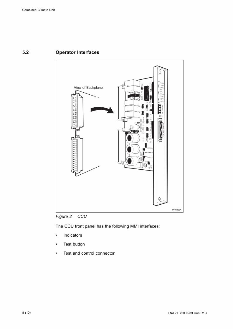
Figure 2 CCU
The CCU front panel has the following MMI interfaces:
• Indicators
• Test button
• Test and control connector
8 (10) EN/LZT 720 0239 Uen R1C

Combined Climate Unit
Indicators
Table 3 Indicators
Indicator ColorCCU Fault Red
Operation Green
Heater fault Yellow
Heat exchanger internal fan fault Yellow
Heat exchanger external fan fault Yellow
Power fault Yellow
EPC bus fault Yellow
Active cooler fan fault Yellow
Active cooler fault Yellow
9 (10)EN/LZT 720 0239 Uen R1C

Combined Climate Unit
Ericsson ABSE-164 80 [email protected]
No part of this document may be reproduced in any form withoutthe written permission of the copyright owner.
The contents of this document are subject to revision withoutnotice due to continued progress in methodology, design andmanufacturing. Ericsson shall have no liability for any error ordamage of any kind resulting from the use of this document.
© Ericsson AB 2004 — All Rights Reserved
10 (10) EN/LZT 720 0239 Uen R1C

EN/LZT 720 0240 Uen R1A
CXU-10
Configuration Switch Unit
Unit Description
The Configuration Switch Unit (CXU) distributes the RX signals from the CDUto the dTRU within the same RBS.
RXI TRU1 RX2 RXI CDU RX2 RXI TRU2 RX2 RXI TRU3 RX2 RXI TRU4 RX2RXI CDU2 RX2 RXI TRU5 RX2 RXI CDU3 RX2 RXI TRU6 RX2Oper Fault
DC/CD U3 CDU busCXU-10 900
P007458A
E 1 (6)

CXU-10
Contents
1 Product Overview 3
1.1 Main Functions 3
2 Dimensions 3
3 Power Consumption 3
4 Function Description 4
4.1 Functions 4
5 Interfaces 5
5.1 Signal and Power Interfaces 5
5.2 Operator Interface 5
2 (6) EN/LZT 720 0240 Uen R1A

CXU-10
1 Product Overview
The CXU cross-connects the CDU and the dTRU in the RX path. The CXUmakes it possible to expand or reconfigure a cabinet with a minimum of movingor replacing of RX cables.
The CXU is a multi-band product for GSM 800, GSM 900, GSM 1800 andGSM 1900.
1.1 Main Functions
The CXU has the following main functions:
• Supports both GMSK and 8-PSK
• One CXU can support up to three CDUs
• To configure the CXU, six switches can be set to connect different CDUswith different dTRUs
2 Dimensions
The CXU-10 has the following dimensions:
Table 1 Size and Weight
Height Width Depth Weight
22 mm 482.6 mm (19"standard)
120 mm 2 kg
3 Power Consumption
The maximum power consumption is 10 W.
3 (6)EN/LZT 720 0240 Uen R1A

CXU-10
4 Function Description
CDUbus
Power-supply
CXU
RX1_TRU1RX2_TRU1
RX1_TRU2RX2_TRU2
RX1_TRU3RX2_TRU3
RX1_TRU4RX2_TRU4
RX1_TRU5RX2_TRU5
RX1_TRU6RX2_TRU6
RX2_CDU3
RX1_CDU3
RX2_CDU2
RX1_CDU2
RX2_CDU1
RX1_CDU1
P007459A
Figure 1 Block Diagram of the CXU
4.1 Functions
The CXU has six different switches. By setting the switches in differentpositions, the CXU can be configured to connect radio signals from a specificCDU to a specific RX input on a dTRU.
The CXU is also connected to a CDU bus. By sending data through the CDUbus, the switches can be set to fulfil one of six supported configurations.
The unit contains splitters for distribution of incoming RX signals to the switchesand in some cases directly to an output.
The RF cables between the CDU and CXU and the CXU and dTRU aresupervised by the CXU.
4 (6) EN/LZT 720 0240 Uen R1A

CXU-10
5 Interfaces
5.1 Signal and Power Interfaces
Table 2 Connectors
Function Qty
Input for RX signal from CDU 6
Output for RX signal to dTRU 12
CDU Bus connector for alarm andconfiguration setting
1
Power supply connector 1
5.2 Operator Interface
Table 3 Indicators
Indicators Color
Operational Green
Fault Red
5 (6)EN/LZT 720 0240 Uen R1A

CXU-10
Ericsson ABSE-164 80 [email protected]
No part of this document may be reproduced in any form without
the written permission of the copyright owner.
The contents of this document are subject to revision without
notice due to continued progress in methodology, design and
manufacturing.
Ericsson shall have no liability for any error or damage of anykind resulting from the use of this document.© Ericsson AB 2004 — All Rights Reserved

1(4)
DCCUDC Connection Unit
Unit Description
EN/LZT 720 0224 R1A
The DC Connection Unit (DCCU) distributes primary power to the PowerSupply Units.
����
��������

2(4)
EN/LZT 720 0224 R1A
Contents
1 Product Overview 31.1 Main Functions 3
2 Dimensions 3
3 Function Description 3
4 Interfaces 34.1 Signal and Power Interfaces 4

3(4)
EN/LZT 720 0224 R1A
1 Product Overview
1.1 Main Functions
The DCCU distributes primary power to the PSUs and it has the followingfunctions:
• Terminates incoming DC supply cables
• Disconnects incoming DC supply
• Filters EMC
2 Dimensions
The DCCU has the following physical characteristics:
Table 1 Size and weight
Height Width Depth Weight
293.5 mm 141 mm 60 mm 5 kg(1)
(1) Including cables
3 Function Description
The DCCU consists of a box containing:
• Terminal block with incoming DC cables
• Eight-pole main switch (disconnecting device)
• A feed-through capacitor filter
• Four cables to the PSUs
4 Interfaces
The DCCU has the following interfaces:
• Terminal block for four incoming DC supply cables
• Four outgoing cables to the PSUs

4(4)
Ericsson Radio Systems ABMobile Telephone SystemsDivision Mobile SystemsSE-164 80 Stockholm, Sweden
Implementation.GSM [email protected]
Due to continued progress in methodology, design and manufacturing,the contents of this document are subject to change without notice.
© Ericsson Radio Systems AB
EN/LZT 720 0224 R1A
4.1 Signal and Power Interfaces
The tables below show input and output data.
Table 2 Input Data
Voltage -40 – -72 V DC
External fuses 4 pcs, max. 40 A
Cable diameter 4.5 – 7 mm
Conductor area 6 – 10 mm2
Number of conductors 2
Table 3 Output Data
Conductor area 6 mm2
Number of conductors 2

EN/LZT 720 0301 Uen R2A
DC/DC Converter
+24 V DC to -48 V DC/DC Converter for RBS 2106
Unit Description
The DC/DC Converter takes +24 V DC and converts it into regulated -48 VDC with an output power of 200 W.
P011010A
FaultOper.
DC/DC-200W
24VIn 10A
48VOut 4A
Alarm
Stop
E 1 (6)

DC/DC Converter
Contents
1 Product Overview 3
1.1 Main Functions 3
2 Dimensions 3
3 Power Consumption and Heat Generation 3
4 Function Description 3
5 Interfaces 4
5.1 Signal and Power Interfaces 5
5.2 Operator Interface 6

DC/DC Converter
1 Product Overview
The DC/DC converter converts +24 V DC battery voltage to regulated -48 VDC. The output power capacity is 200 W.
1.1 Main Functions
The DC/DC Converter has the following main functions:
• Converts voltage
• Limits current
• Regulates voltage
• Protects from overvoltage and undervoltage
• Provides remote-controlled start and stop
2 Dimensions
This section describes the physical characteristics of the DC/DC Converter.
Table 1 Size and Weight
Height Width Depth Weight
262 mm (6 HE x44.45 mm)
40,3 mm (8 TE x5.08 mm)
159 mm 1.3 kg
3 Power Consumption and Heat Generation
The maximum power consumed and heat generated during use are shown inthe table below.
Table 2 Maximum Power and Heat
Max power consumption Max heat generation
225 W 25 W
4 Function Description
This section dscribes the function of the DC/DC Converter.

DC/DC Converter
P009809B
Input +24 V Output -48 V DC
Output -48 V DC
Input ALARM
Input Stop
Output AlarmControl Circuit
Figure 1 DC/DC Converter Block Diagram
The unit is a switched converter, that converts +24 V DC battery voltage toregulated -48 V DC. The converter can be connected in parallel with otherconverters to operate continuously in current limitation mode.
The current limitation is set to 100 - 115% of the rated current (4.0 A), abovewhich the output voltage drops. The output current increases when the voltagedrops, enabling the converter to be loaded with other DC/DC converters with aninput power limited to approximately 150 W.
The overvoltage protector shuts down the switching when the output voltagereaches -58 V. The DC/DC Converter reconnects after approximately 10seconds when the output voltage decreases to nominal level. If this occurs fivetimes, the converter will shut down and be blocked. To restart the converter,the input voltage supply must be disconnected and then reconnected afterapproximately 10 seconds.
The undervoltage protector monitors the input voltage and blocks the converterat an input voltage of 18 ±0.5 V. The converter starts automatically when theinput voltage exceeds the start level, 20V ±0.5.
The converter can be stopped remotely by connecting a +5 V signal to the pin"Stop". Normally this pin is left unconnected.
A green indicator on the front indicates that an input voltage, which hasreached starting level, is present in the conversion stage. A red indicator on thefront is active when the output voltage is out of range due to either overload,overvoltage, or failure.
5 Interfaces
This section describes the interfaces of the DC/DC Converter.

DC/DC Converter
P011027A
DC/DC-200W
FaultOper.
Alarm
Stop
48VOut 4A
24VIn 10A
Figure 2 DC/DC converter Interfaces
5.1 Signal and Power Interfaces
Input data
Table 3 Input Data
Nominal voltage +24 V DC
Permitted variations +18.0 ±0.5 to 29.0±0.5 V DC
Default start level +23.5 ±0.2 V DC
Default undervoltage stop level +18.5 ±0.2 V DC
Default overvoltage stop level 31.0 ±0.5 V DC
Restart level after overvoltage 29.0 ±0.5 V DC
Rated power 200 W

DC/DC Converter
Output data
Table 4 Output Data
Rated voltage –54 V DC
Default output –54 V DC
Overvoltage protection –58 ±1 V DC
Undervoltage alarm –44.0 ±1 V
Output current 4.0 A at –54 V DC
Efficiency at 200 W output >88% at Iout=4.0 Aand 27 V DC input
Current or power limitation at U (out): 225 W
5.2 Operator Interface
The DC/DC Converter has the following interfaces, all located on the front panel:
• ON/OFF switch
• Start and Stop pin
Indicators
Table 5 Indicators
Indication Colour
Input OK Green
Output fail Red
Ericsson ABSE-164 80 [email protected]
The contents of this document are subject to revision withoutnotice due to continued progress in methodology, design and
manufacturing.Ericsson shall have no liability for any error or damages of any
kind resulting from the use of this document.© Ericsson AB 2003 — All Rights Reserved

EN/LZT 720 0302 Uen R1A
DC Filter for RBS 2106
Filter for External BatteriesDescription
The DC Filter Unit is the RBS 2106’s interface for external +24 V DC powersupply.
������������ ���������������
����
���
���
��������������
��������������
E 1 (4)

DC Filter for RBS 2106
Contents1 Product Overview 31.1 Main Functions 3
2 Dimensions 3
3 Function Description 3
4 Interface 44.1 Signal and Power Interface 4
2 (4) EN/LZT 720 0302 Uen R1A

DC Filter for RBS 2106
1 Product OverviewThe DC Filter is the interface between a +24 V DC external power source, suchas a battery, and the IDM inside the RBS 2106.
1.1 Main Functions
The DC Filter has the following main functions:
• EMC filtering
• Connection of +24 V DC to the cabinet
• Distribution of +24 V DC power to the IDM
2 DimensionsThe DC Filter has the following dimensions:
Table 1 Size and Weight
Height Width Depth Weight121 mm 222 mm 171 mm 5 kg
3 Function Description
�������
��
!�" ������
�
�
�
�
Figure 1 Circuit Diagram
This unit filters the incoming +24 V DC to conform with the internal requirementsof the RBS 2106.
The filter is formed by a coaxial feed-through capacitor. The capacitor providesfull 360 earthing around the cable.
The DC Filter serves as an EMC barrier against the outside electricalenvironment and a mechanical barrier against the outside climatic environment.
3 (4)EN/LZT 720 0302 Uen R1A

DC Filter for RBS 2106
4 Interface4.1 Signal and Power Interface
he DC Filter has the following external interfaces:
• Two input terminals for 70 - 185 mm2 cables. The input terminals are ofsemi-enclosed clamp type
• Strain-relief clamps for cables with diameter 14 - 26 mm
• Output cable negative (-) is a 70 mm2 cable, about 420 mm long, with anAnderson power plug
• Output cable positive (+) is a 70 mm2 cable, about 420 mm long, with anAnderson power plug
• A hole for an optional temperature sensor connector is provided
Voltage and Current
Table 2 Limiting values
Rated voltage 100 V DC
Feed-through current 175 A
Ericsson ABSE-164 80 [email protected]
No part of this document may be reproduced in any form withoutthe written permission of the copyright owner.
The contents of this document are subject to revision without
notice due to continued progress in methodology, design andmanufacturing.
Ericsson shall have no liability for any error or damage of anykind resulting from the use of this document.© Ericsson AB 2004 — All Rights Reserved

EN/LZT 720 0241 Uen R1B
DC Filter 01 for RBS 2206 and RBS 2207Description
The DC filter is the interface for +24 V DC supply to the cabinet.
P008243B
E 1 (4)

DC Filter 01 for RBS 2206 and RBS 2207
Contents1 Product Overview 31.1 Main Functions 3
2 Dimensions 3
3 Function Description 3
4 Interface 44.1 Signal and Power Interfaces 4
2 (4) EN/LZT 720 0241 Uen R1B

DC Filter 01 for RBS 2206 and RBS 2207
1 Product Overview1.1 Main Functions
The DC filter has the following main functions:
• Provides the interface for +24 V DC supply to the cabinet
• Distributes +24 V DC to the Internal Distribution Module (IDM)
2 DimensionsThe DC filter has the following dimensions:
Table 1 Size and Weight
Height Width Depth Weight293.5 mm 164 mm 70 mm 6 kg (incl. cables)
3 Function DescriptionThe DC-filter has the following functions:
• Filters EMC
• Connects incoming 70 - 185 mm2 power cables
• Protects incoming cables from pulling forces
• Power connection for internal distribution
3 (4)EN/LZT 720 0241 Uen R1B

DC Filter 01 for RBS 2206 and RBS 2207
4 Interface4.1 Signal and Power Interfaces
The DC-filter has the following external interfaces:
• Two input terminals for 70 - 185 mm2
• Pull-relief clamps for incoming power cables with diameter 14 - 26 mm
• Two 70 mm2 output cables
Table 2 Input Data
Input voltage Nominal +24 V DCRange 20.0 - 29.0 V DC
Non-destructive range 0.0 - +32.0 V DC
Max input current 200 A
Ericsson ABSE-164 80 [email protected]
No part of this document may be reproduced in any form withoutthe written permission of the copyright owner.
The contents of this document are subject to revision withoutnotice due to continued progress in methodology, design andmanufacturing. Ericsson shall have no liability for any error ordamage of any kind resulting from the use of this document.
© Ericsson AB 2004 — All Rights Reserved
4 (4) EN/LZT 720 0241 Uen R1B

EN/LZT 720 0242 Uen R1A
dTRU
Double Transceiver UnitUnit Description
The double Transceiver Unit (dTRU) is a 2-TRX replaceable unit. A TRX is atransmitter/receiver and signal-processing unit, which transmits and receivesone carrier.
��������
��
�����
� ��
����
� ���� �
���� ��
��
��
�� � ��
�������
������������������� !�"��
!�"��#��$���
E 1 (6)

dTRU
Contents1 Product Overview 31.1 Main Functions 3
2 Dimensions 3
3 Power Consumption and Heat Generation 3
4 Function Description 44.1 CPU System 54.2 DSP System 54.3 Radio Control System 54.4 Radio System 5
5 Interfaces 65.1 Signal and Power Interfaces 65.2 Operator Interface 6
2 (6) EN/LZT 720 0242 Uen R1A

dTRU
1 Product OverviewThe dTRU is a 2-TRX replaceable unit. A TRX is a transmitter/receiver andsignal-processing unit, which transmits and receives one carrier. There aredifferent versions of dTRU depending on the frequency band and modulationcapability, that is, both GMSK and 8PSK (EDGE) or GMSK only.
The dTRU has two TX antenna terminals and four RX antenna terminals. ThedTRU features a built-in hybrid combiner. The hybrid combiner can be used tocombine the two TX antenna terminals to one common terminal.
Two of the RX antenna terminals are used for 2-branch diversity reception.The dTRU is hardware prepared for 4-branch diversity reception through theremaining two antenna terminals.
1.1 Main Functions
The dTRU is a distributed main CPU DMCN and its main functions are:
• Transmits and receives radio frequency signals - GMSK or 8PSKmodulation
• Processes signals
2 DimensionsThe dTRU has the following dimensions:
Table 1 Size and Weight
Height Width Depth Weight400 mm (9 HE x44.45 mm)
71 mm (14 TE x5.08 mm)
270 mm 7.6 kg
3 Power Consumption and Heat GenerationTable 2 Power Consumption and Heat Generation
Max. power consumption Max. heat generation485 W 380 W
3 (6)EN/LZT 720 0242 Uen R1A

dTRU
4 Function Description
��
���%��&�
�'���$()���*+,�
�'���$���'���$ ������'���$
+,��'���$
���'���$
���������)$�����
�'-���"�$-
� �
�
� ��� �
���
�
� �
���
� �
������"��.��
������"��.��
���������)$�����
� �"���
� �����
������� ������/ �"���
������� ������/ �"���
� �"���
� �����
�����,'���$
()���*
�+)� �"����-��
/
�
/�
Figure 1 Block diagram of the dTRU
The TRU consists of the following main blocks:
• CPU system
• DSP system
• RC system
• Radio system
4 (6) EN/LZT 720 0242 Uen R1A

dTRU
4.1 CPU System
The CPU system is a control unit in the RBS. It consists of a CPU, supportlogic, memory and logic for handling the interfaces.
4.2 DSP System
The DSP system performs all baseband signal processing necessary for oneTRX. For downlink, this includes Terrestrial Protocol Handling (TPH), encoding,ciphering and burst generation. For uplink it includes equalization, combining,decoding and TPH.
4.3 Radio Control System
The RC system is responsible for synchronizing and controlling the differentparts of the radio, for modulation and D/A conversion of the data to transmit,for filtering the received radio signal with a channel selective filter and forcompensating the RX and TX delay and gain variations.
The RC system is seen by the rest of the RBS as the front end to the radio,which can be asked to transmit a burst of data using a selected modulation, orasked to receive a burst using a selected digital filter.
All time critical radio control functions are performed by the RC system and nocomputing support is required from the CPU system on a real-time basis.
4.4 Radio System
Each radio system contains two radio receivers and one radio transmitterincluding power amplifiers.
The radio receiver receives RF modulated uplink data from one or two diversitybranches and sends it to the RC system.
The radio transmitter generates the RF downlink signal from the modulatedbaseband signal. It then sends the RF signal to the power amplifier, whichamplifies the downlink RF signals.
5 (6)EN/LZT 720 0242 Uen R1A

dTRU
5 InterfacesThe dTRU has the following external interfaces:
• CDU-TX control bus, IOM bus
• IOM bus, LEDs and buttons
• RX (front)
• TX (front)
• Y link
5.1 Signal and Power Interfaces
The Y link, CDU TX control bus, system voltage and connectors are locatedon the backplane.
5.2 Operator Interface
Table 3 Indicators
Indicator ColorFault Red
Operational Green
RF off Yellow
Local mode Yellow
Table 4 Switches
Switch FunctionTRU reset Resets the TRU
Local/remote Local/remote mode
Ericsson ABSE-164 80 [email protected]
No part of this document may be reproduced in any form withoutthe written permission of the copyright owner.
The contents of this document are subject to revision without
notice due to continued progress in methodology, design andmanufacturing.
Ericsson shall have no liability for any error or damage of anykind resulting from the use of this document.© Ericsson AB 2004 — All Rights Reserved

EN/LZT 720 0244 Uen R2A
DXU-21 A
Distribution Switch Unit
Unit Description
The Distribution Switch Unit (DXU) is a unit, which acts as an interfacebetween the transmission network and the transceivers. It also extracts timinginformation from the transmission interfaces and generates a timing referencefor the RBS.
P009064B
Local
FaultOperational
RSB FaultExt AlarmsEPCbus faultBattery mode
DXU reset
Local Remote
EPC bus
V7-12
V 1-6
Statu
Port A
Port B
Port BPort A
Port DPort C
Port C
Port D
OMT ESB
GPS
Y link
TD
RD
Transmission
A
E 1 (12)

DXU-21 A
Contents
1 Product Overview 3
1.1 Main Functions 3
2 Dimensions 3
3 Power Consumption and Heat Generation 3
4 Function Description 4
4.1 CPU System 6
4.2 Communication Switch System 6
4.3 Transmission Interface Controller 6
4.4 Power Supply 6
4.5 Timing System 6
4.6 Miscellaneous Logic 7
4.7 Compact Flash Card 7
5 Interfaces 8
5.1 Signal and Power Interfaces 8
5.2 Operator Interface 10
2 (12) EN/LZT 720 0244 Uen R2A

DXU-21 A
1 Product Overview
The DXU-21 is a CPU, which acts as an interface between the transmissionnetwork and the transceivers. It also extracts timing information from thetransmission interfaces and generates a timing reference for the RBS. TheDXU also performs supervisory tasks. The DXU-21 transmission interface haslong-haul capability and can be configured to both 1.544 Mbit/s (T1) and 2.048Mbit/s (E1) transmission interface modes.
1.1 Main Functions
The DXU serves as the Central Main CPU node and its main functions are:
• Provides the RBS with an interface to the transport network through fourfixed E1/T1 transmission ports
• Handles incoming traffic, controls and supervises information and sendsit to its destination within the RBS
• Provides frequency reference signals and timing signals for circuits withinthe RBS
• Stores and executes RBS SW stored on a removable flash card
• Controls the climate and power system
2 Dimensions
The DXU-21 has the following dimensions:
Table 1 Size and weight
Height Width Depth Weight
227 mm (6 HE x44.45 mm
71 mm (14 TE x5.08 mm)
240 mm 2.4 kg
3 Power Consumption and Heat Generation
Table 2 Power Consumption and Heat Generation
Max power consumption Max heat generation
40 W (typical 30 W) 40 W
3 (12)EN/LZT 720 0244 Uen R2A

DXU-21 A
4 Function Description
Electrically, the DXU-21 consists of the following main blocks:
• CPU system
• Communication switch system
• Transmission interface controller
• Power supply
• Timing system
• Miscellaneous logic
• Compact Flash Card
The relations of these main blocks are shown in the following figure.
4 (12) EN/LZT 720 0244 Uen R2A

DXU-21 A
Ext. Synt. Source (GPS)
Ext. Synt. Source (TG-sync)
O&M Terminal (EOM)
EPC bus
Transm.ports;
Ylinks
Transm.InterfaceController
OPT-inputs
OPT-outputs
External alarms
Vcc for backplane memory
IOM-bus
Cabinet LEDs
Rack/Shelf/unit pos
Da-in/out
Timing bus
CompactFlashCardInterface
CPU System
Part oftimingsystem
OVCXO+DAC
5 MHz
MMI
DXU
Communicationswitch system
Powersupply
Local bus
+24V
P007457B
A
B
C
D
Figure 1 DXU-21, block diagram
5 (12)EN/LZT 720 0244 Uen R2A

DXU-21 A
4.1 CPU System
The heart of the DXU-21 is a 32-bit embedded controller with interfaces toa wide range of peripherals.
The CPU system consists of:
• I2C controller
• SDRAM memory
• FLASH memory
• ASIC GARP
• Compact Flash Card
4.2 Communication Switch System
This system block contains circuits that handle traffic between the BSC andthe dTRUs.
4.3 Transmission Interface Controller
This part contains circuits for four transmission ports and the transmissioninterface controller, which controls the traffic for all four transmission ports.
The bit rate is SW controlled. Two speeds are available: E1 (2.048 Mbit/s)or T1 (1.544 Mbit/s).
4.4 Power Supply
The power supply delivers all the voltages necessary for the DXU-21. The inputvoltage, +24 V DC, is supplied through backplane connectors.
4.5 Timing System
The timing system is used for generating a 13 MHz clock signal.
6 (12) EN/LZT 720 0244 Uen R2A

DXU-21 A
4.6 Miscellaneous Logic
This function contains the following:
• System voltage measurement
• Temperature measurement
• Power on reset
4.7 Compact Flash Card
The removable Compact Flash Card permits quick and easy change of the SWand IDB in the DXU.
7 (12)EN/LZT 720 0244 Uen R2A

DXU-21 A
5 Interfaces
This section describes the signal and power interfaces, and the operatorinterface, of the DXU.
5.1 Signal and Power Interfaces
Transmission Interface
The four transmission interfaces are connected to the BSC (Protocol GSM-Abis)or to cascaded base stations. In cascade mode, this interface can controlan external bypass relay. Unused time slots can be through-connected to asuccessive base station. The communication speed in E1 interfaces is 2 Mbit/sand in T1, 1.5 Mbit/s.
External Alarm Inputs
Through this interface it is possible to connect up to 15 binary alarms (16including one dedicated alarm). This interface is found on the upper backplaneconnector.
The equipment connected to the terminals should be insulated relay contacts.A closed contact (logic zero) is required to be below 2 k , and an open contact(logic one) is required to be above 100 k .
The current through a closed 0 contact is 1.2 mA.
The alarm contacts connected to the external alarm inputs should be insulatedand have a current range above 1.2 mA. The voltage between terminals withan open contact is +24 V DC.
Local Bus
The local bus is a time slot and multidrop bus, where the DXU-21 is the masterof the bus. Two identical local buses are implemented, with common framesynchronization and clock signals. The interface is accessed through the lowerbackplane connector. The local bus is used for TRUs.
Timing Bus
This interface is used for distribution of timing information to the TRUs throughthe backplane. The interface is accessed through the lower backplaneconnector. The timing bus is only used for TRUs.
8 (12) EN/LZT 720 0244 Uen R2A

DXU-21 A
Optional Output
This interface enables control of up to eight devices, which can be of varioustypes. These outputs are accessed through the upper backplane connector.
Optional Input
This interface enables connection of up to eight internal cabinet signals, suchas alarms. These inputs are accessed through the upper backplane connector.
IOM Bus
This interface consists of three individual I2C ports. It is used to communicatewith the CDU, CXU and cabinet ID.
An I2C bus is reserved for reading a memory device which identifies the sourcefor the system.
The interface is accessed through the lower backplane connector.
Y Links
This interface is used for communication with the dTRUs and sTRUs. The Yinterface consists of 12 separate Y links.
The Y links are accessed through connectors located on the front of the DXU.
EPC Bus (Optical Cable)
This interface is used for communication with the power supply equipmentin the RBS, such as PSUs and BFU.
The optical communication interface is accessible through connectors locatedon the front of the DXU. The connectors are marked "EPC".
External Sync.
This interface is used for interfacing an external sync./frequency source, suchas GPS. It is accessed through a connector of type 8-pin RJ-45, located on thefront of the DXU. The connector is marked "GPS".
ESB
This interface is used to synchronize several transceiver groups in the samecell, for example when one cell is built up by more than one RBS, or one cell issplit between two RBSs.
9 (12)EN/LZT 720 0244 Uen R2A

DXU-21 A
Note: A master-extension configuration, as in RBS 2202, is regarded as onetransceiver group.
The interface is accessed on the front of the DXU through a D-sub 9-pin maleconnector marked "ESB".
5.2 Operator Interface
This section describes the operator interface, which consists of the OMTinterface and indicators and buttons.
OMT
The OMT port is used to communicate with the Operation and MaintenanceTerminal.
The OMT is connected through a 9-pin D-sub female connector.
The OMT connection is galvanically separated. All signals use RS 232 levels.
Table 3 The OMT Connector Pins and their Functions
Pin Function
1 DCD, looped from DTR (pin 4)
2 RXD, data out of DXU
3 TXD, data into DXU
4 DTR, looped to DCD (pin 1) and DSR (pin 6)
5 Signal ground
6 DSR, looped from DTR (pin 4)
7 RTS, looped to CTS (pin 8)
8 CTS, looped from RTS (pin 7)
9 RI not connected
10 (12) EN/LZT 720 0244 Uen R2A

DXU-21 A
Indicators and Buttons
There are 11 indicators located on the front panel (as shown in the table below)and two buttons for DXU Reset and Local/remote.
Table 4 Indicators
Indicator Colour
Fault Red
Operational Green
Transmission OK (port A, B, C, D) Green (4 pcs)
Local Yellow
RBS fault Yellow
External alarm Yellow
EPC bus fault Yellow
Battery mode Yellow
Table 5 Switches
Switch Function
DXU reset Resets the DXU
Local remote Sets local/remote mode
11 (12)EN/LZT 720 0244 Uen R2A

DXU-21 A
Ericsson ABSE-164 80 [email protected]
No part of this document may be reproduced in any form withoutthe written permission of the copyright owner.
The contents of this document are subject to revision withoutnotice due to continued progress in methodology, design and
manufacturing.Ericsson shall have no liability for any error or damages of any
kind resulting from the use of this document.© Ericsson AB 2003 — All Rights Reserved
12 (12) EN/LZT 720 0244 Uen R2A

EN/LZT 720 0246 Uen R1A
FCU-01
Fan Control UnitUnit Description
The Fan Control Unit (FCU) controls and supervises the fans in the RBS 2206.It has indicators that show fan status information.
��������
E 1 (6)

FCU-01
Contents1 Product Overview 31.1 Main Functions 3
2 Dimensions 3
3 Function Description 3
4 Interfaces 44.1 Signal and Power Interface 44.2 Operator Interface 4
2 (6) EN/LZT 720 0246 Uen R1A

FCU-01
1 Product OverviewThe Fan Control Unit (FCU) controls and supervises the fans in an RBS cabinet.
1.1 Main Functions
The FCU-01 has the following main functions.
• Controls and supervises fans
• Generates alarm
• MMI for the fans
2 DimensionsThe FCU-01 has the following physical characteristics:
Table 1 Size and Weight
Height Width Depth Weight195 mm 98 mm 45 mm 0.5 kg
3 Function DescriptionThe FCU receives information on the EPC bus about the required DC voltagelevel for each fan. It feeds each fan with the required DC voltage level. If noDC level is received, the DC level for the fans will be equal to the FCU inputvoltage, minus a maximum voltage drop of 0.7 V.
If the normally closed circuit in the fan is opened, the indicator "Fan fault" forthat fan is illuminated, and an alarm is sent through the EPC bus.
The FCU compares the DC level for each fan with the required DC level. Ifthese do not match, the indicator ‘‘FCU fault’’ is illuminated, and an alarm issent through the EPC-bus.
If the communication on the bus no longer is defined, the indicator ‘‘EPC busfault’’ is illuminated, and an alarm is sent through the EPC bus to the DXU.
3 (6)EN/LZT 720 0246 Uen R1A

FCU-01
4 InterfacesThe FCU has the following interfaces:
• Power in
• EPC bus in
• EPC bus out
• Fan power and alarm (1 - 4)
4.1 Signal and Power Interface
The tables below show input and output data.
Table 2 Input Data
Nominal input voltage +24.0 V DC
Input voltage range +19.0 - +29.0 V DC
Non destructive voltage 0.9 - +32.0 V DC
Input power 4 x 45 W
Table 3 Output Data
Output voltage 9 - 28.3 V DC
Output current Min 1.8 A at 9 - 28.3 V DC
4.2 Operator Interface
There is one alarm signal for each fan. The alarm circuit is normally closed.
An open circuit indicates that the fan speed is too low. The fan has an opencollector interface.
Table 4 No Alarm
Alarm pos. Upos 5 - 30 V DC
Alarm neg. Upos <Upos- 2.4 V DC
Current Ino_alarm 5 - 20 mA
4 (6) EN/LZT 720 0246 Uen R1A

FCU-01
Table 5 Alarm
Alarm pos. Upos 5 - 30 V DC
Alarm neg. Upos < 2 V DC
Current Ino_alarm < 5 mA
Indicators
Table 6 Indicators
Indicator ColorFault Red
Operational Green
EPC bus fault Yellow
Fan 1 fault Red
Fan 2 fault Red
Fan 3 fault Red
Fan 4 fault Red
5 (6)EN/LZT 720 0246 Uen R1A

FCU-01
Ericsson ABSE-164 80 [email protected]
No part of this document may be reproduced in any form withoutthe written permission of the copyright owner.
The contents of this document are subject to revision without
notice due to continued progress in methodology, design andmanufacturing.
Ericsson shall have no liability for any error or damage of anykind resulting from the use of this document.© Ericsson AB 2004 — All Rights Reserved

EN/LZT 720 0449 Uen R1A
HCUHybrid Combiner Unit
Unit Description
The HCU combines the signals from two dTRUs into a common output, thusexpanding capacity without increasing the number of antennas.
P011028A
TRU6
CDU3
TX1
HCU 8-900
TRU1
TRU2
TRU3
800 900
CDU1
TX1
CDU2
TX1
TRU5
TRU4
E 1 (6)

HCUHybrid Combiner Unit
Contents
1 Product Overview 3
2 Dimensions 3
3 Function Description 3
4 Interfaces 4
2 (6) EN/LZT 720 0449 Uen R1A

HCU Hybrid Combiner Unit
1 Product Overview
The HCU contains three hybrid combiners. Each hybrid combines two RFsignals, delivered from the dTRU, into one. This is then passed to the CDU.This gives an expanded capacity using a minimum of TX/RX antennas. (Thereis no need to increase the number of TX antennas or to build a new site.) TheHCU covers both GSM 800 and GSM 900.
2 Dimensions
The HCU has the following dimensions:
Table 1 Size and Weight
Height Width Depth Weight
22 mm 482.6 mm (19’standard)
236.6 mm(1) <3.5 kg
(1) The HCU protrudes 40 mm from the rack (including the front panel)
3 Function Description
This section describes the function of the HCU.
P011003A
SUBUNIT 1
TX1 TX2
LOAD TX1+TX2
SUBUNIT 3
TX1 TX2
LOAD TX1+TX2
SUBUNIT 2
TX1 TX2
LOAD TX1+TX2
Figure 1 Block diagram for HCU
A dTRU has an internal hybrid combiner, which can combine the twotransmitters into a common output. A CDU-G has no further combining functionfor the transmitted signal. If further combining is required, the Hybrid CombiningUnit (HCU) must be introduced.
The HCU can combine the already combined signal from two dTRUs into acommon output. The benefit is that it is possible to expand capacity withoutincreasing the number of antennas. Synthesizer hopping is supported, and
3 (6)EN/LZT 720 0449 Uen R1A

HCUHybrid Combiner Unit
using a HCU with a CDU-G makes synthesised frequency hopping possible.The drawback is that the output power is reduced by half.
The HCU is a passive unit that does not require power feeding.
4 Interfaces
This section describes connectors on the HCU.
Connectors
P011095A
TRU1 TRU2 TRU3 TRU4 TRU5 TRU6CDU1
TX1
CDU2
TX1
CDU3
TX1HCU 8-900 800 900
1 2 3 4 7 8 95 6
Figure 2 HCU Connectors
Table 2 HCU Connectors
Position HCU Label Connects to
1 TX1 dTRU 1
2 TX1+TX2 CDU-G 1.TX1
3 TX2 dTRU 2
4 TX1 dTRU 3
5 TX1+TX2 CDU-G 2:TX1
6 TX2 dTRU 4
7 TX1 dTRU 5
8 TX1+TX2 CDU-G 3.TX1
9 TX2 dTRU 6
4 (6) EN/LZT 720 0449 Uen R1A

HCU Hybrid Combiner Unit
Input Data
Table 3 Input Ports
Port Marking
Input 1..6 TRU1..TRU6
Output Data
Table 4 Output Ports
Port Marking
Output 1, 2, 3 CDU1 TX1, CDU2 TX1, CDU3 TX1
Indicators
The HCU does not have any indicators.
5 (6)EN/LZT 720 0449 Uen R1A

HCUHybrid Combiner Unit
Ericsson ABSE-164 80 [email protected]
No part of this document may be reproduced in any form withoutthe written permission of the copyright owner.
The contents of this document are subject to revision withoutnotice due to continued progress in methodology, design and
manufacturing.Ericsson shall have no liability for any error or damages of any
kind resulting from the use of this document.© Ericsson AB 2003 — All Rights Reserved
6 (6) EN/LZT 720 0449 Uen R1A

EN/LZT 720 0311 Uen R1A
Heat Exchanger Climate Unit
Climate Unit for RBS 2106Description
The Heat Exchanger Climate Unit provides the RBS 2106 with cooling orheating to keep the operating temperature within specified limits. The unitcontains a heat exchanger, a heater, air-ducts and fans.
��������
��������
E 1 (10)

Heat Exchanger Climate Unit
Contents1 Product Overview 31.1 Main Functions 3
2 Dimensions 3
3 Power Consumption 3
4 Function Description 44.1 Heat Exchanger 54.2 Heater 54.3 Climate Control Unit 54.4 AC/DC Converter 64.5 Autotransformer 6
5 Interfaces 75.1 Signal and Power 75.2 Operator Interface 7
2 (10) EN/LZT 720 0311 Uen R1A

Heat Exchanger Climate Unit
1 Product OverviewThe Heat Exchanger Climate Unit provides the RBS 2106 with cooling orheating to keep the operating temperature within specified limits. The unitcontains a heat exchanger, a heater, air-ducts and fans.
1.1 Main Functions
The Heat Exchanger Climate Unit maintains the cabinet operating temperaturewithin specified limits by heating or cooling.
2 DimensionsThe Heat Exchanger Climate Unit has the following dimensions:
Table 1 Size and Weight
Height Width Depth Weight1250 mm 1050 mm 250 mm 97 kg
3 Power ConsumptionPower consumption information for the Heat Exchanger Climate Unit is shownin the table below.
Table 2 Power Consumption
Max AC power consumption Max DC power consumption2100 W (at 230 V 50 Hz) 650 W
3 (10)EN/LZT 720 0311 Uen R1A

Heat Exchanger Climate Unit
4 Function Description
��������
��� ���
���� ��������� ���
��� ����� ����� ���!"#�$��
������
�% ���&!
����� ���
�������������
Figure 1 Block Diagram
The Heat Exchanger Climate Unit consists of the following units:
• Heat Exchanger
• Heater
• Climate Control Unit (CCU)
• AC/DC Converter
• Transformer
4 (10) EN/LZT 720 0311 Uen R1A

Heat Exchanger Climate Unit
4.1 Heat Exchanger
The heat exchanger consists of a cross-flow heat exchanger and internal andexternal air circuit fans.
Outside (ambient) air is forced through one side of the heat exchanger byDC-powered fans. There it cools the inside air which circulates through theother side of the heat exchanger.
Because ambient air is used on the ’cool’ side of the heat exchanger, coolingcapacity is limited to the temperature outside the cabinet. If the ambienttemperature is higher than the cabinet return air temperature, the external aircirculation fan will stop to prevent the outside air warming the cabinet.
4.2 Heater
The heater is placed in the internal air circuit. It operates at cold start-up,heating the inside air when the temperature inside the cabinet is below +5 C.The heater is not normally at any point other than cold start-up.
The heater is powered by AC mains voltage and is controlled by the ClimateControl Unit. Its two heating coils have a total capacity of 2 kW.
4.3 Climate Control Unit
The Climate Control Unit (CCU) is a processor-based plug-in unit, controllingand supervising the climate unit. The CCU provides the following mainfunctions:
• Monitors internal and external temperatures
• Monitors and controls the internal and external fans
• Monitors and controls the compressor
• Monitors and controls the condensor fan
• Monitors and controls the heater
• Handles alarms
• Supervises Mains Voltage
• Tests the Heat Exchanger Climate Unit
5 (10)EN/LZT 720 0311 Uen R1A

Heat Exchanger Climate Unit
Parameters
The CCU has a set of default operating parameters, which can be overriddenby loaded parameters. These are sent to the CCU through the EPC-bus.Parameters which can be changed are the following:
• Temperature range for linear speed control of internal fan
• Temperature range for linear speed control of external fan
• Temperature range for heater on and off
Backplane and Front Panel
The backplane connectors contain the climate unit internal interfaces to DCpower, AC power, fans, temperature sensors, and so on.
The front panel contains indicators, connectors for the EPC bus and for testand control.
4.4 AC/DC Converter
The AC/DC converter is used when +24 V DC supply is shut off. It changes themains voltage to +24 V DC, to supply the internal air circuit fan, the externalcircuit fan in the heat exchanger, and the CCU.
4.5 Autotransformer
The transformer converts different AC mains input voltages to 230 V AC forfeeding the heater, the AC/DC converter and fans.
The transformer has windings for mains input voltages of 200, 208, 230, 240and 250 V AC. The mains voltage is selected with the Voltage Selector Switch.
Connection to 120 V AC is made between phases with 208 V AC selected.Other voltages are connected between phase and neutral.
6 (10) EN/LZT 720 0311 Uen R1A

Heat Exchanger Climate Unit
5 Interfaces5.1 Signal and Power
The Heat Exchanger Climate Unit has the following external interfaces:
• DC power
• AC mains power
• EPC bus (on the CCU)
• Test and general signals (25-pole D-sub on the CCU)
The Y link, CDU TX control bus, system voltage and connectors are locatedon the backplane.
5.2 Operator Interface
���'��(�
) ��
��� *
* �
�� �
* �+ *(
�� (�* �
�* (
�* ,
�* � * (
�� ��!��
-���.�����#����- #""/#���
/#������$#��
Figure 2 CCU
7 (10)EN/LZT 720 0311 Uen R1A

Heat Exchanger Climate Unit
The CCU front panel has the following MMI interfaces:
• Test and general signals connector
• EPC bus connectors
• Test button
• Indicators
Test and Control Connector
The test and general signals connector is a 25-pole D-sub connector.
Table 3 Indicators
Indicator Description ColorCCU FAULT Fault Red
OPERATION Operational Green
EPC BUS EPC-bus fault Yellow
HEAT FAULT Heater fault Yellow
HE.INT.FAN Heat exchangerinternal fan fault
Yellow
HE.EXT.FAN Heat exchangerexternal fan fault
Yellow
PWR.FAULT Power fault Yellow
EPC-bus Connectors
The EPC-bus is an optional communication bus used for RBS communication.
Table 4 EPC-bus Connectors
Connector FunctionTD Transmit
RD Receive
8 (10) EN/LZT 720 0311 Uen R1A

Heat Exchanger Climate Unit
Test Button
The test button on the front panel of the CCU activates the test function. Afterthe test has been completed, the indicators will present the status for twominutes. No alarm is sent if there is a malfunction.
The total test time is approximately 6.5 minutes. During that time, the followingare checked:
• External fan
• Internal fan
• Heater active
• Normal operation/failure information from the indicators
9 (10)EN/LZT 720 0311 Uen R1A

Heat Exchanger Climate Unit
Ericsson ABSE-164 80 [email protected]
No part of this document may be reproduced in any form withoutthe written permission of the copyright owner.
The contents of this document are subject to revision without
notice due to continued progress in methodology, design andmanufacturing.
Ericsson shall have no liability for any error or damage of anykind resulting from the use of this document.© Ericsson AB 2004 — All Rights Reserved

EN/LZT 720 0247 Uen R1A
IDM
Internal Distribution ModuleUnit Description
The Distribution Module (IDM) distributes +24 V DC to all DC powered unitsin the RBS.
��������
����������������� ��
��������
���������
������� �����
�� ������
��������
��������
������� �����
����������
��������
��������
�������
� ���!�� �����
� �"���#$�#����#��
% �����
% �����
% �����
% �����
��������
% ������
&�'!��
�������
E 1 (6)

IDM
Contents1 Product Overview 31.1 Main Functions 3
2 Dimensions 3
3 Function Description 3
4 Interface 44.1 Signal and Power Interfaces 44.2 Operator Interface 5
2 (6) EN/LZT 720 0247 Uen R1A

IDM
1 Product OverviewThe Internal Distribution Module distributes +24 V DC to all DC powered unitsin the RBS. Distribution circuits are protected by circuit breakers.
1.1 Main Functions
The IDM consists of a unit with 21 circuit breakers, four PSU cables andconnectors to the different DC powered units.
2 DimensionsThe IDM has the following dimensions:
Table 1 Dimensions
Height Width Depth Weight133 mm 483 mm 80 mm 5 kg
3 Function DescriptionThe IDM has the following external interfaces:
• Four PSU cables
• Battery connection (positive)
• Battery connection (negative) and earth connection
• System voltage test port
• ESD wrist-strap connector
• Power distribution connectors (see table below)
3 (6)EN/LZT 720 0247 Uen R1A

IDM
4 Interface4.1 Signal and Power Interfaces
Input Data
Table 2 Input data
Nominal input voltage range 24 V DC
Input voltage +20.0 - +29.0 V DC
Non-destructive range 0.0 - +32.0 V DC
Input power 4800 W
Output Data
Maximum voltage drop from the input to the output of the IDM is 0.3 V DC.
Table 3 Circuit Breaker Capacity
Circuit breaker Capacity QuantityCXU 1 - 2, OXU 5 5A 1
Fan 1 - 4 5A 4
OXU 1 - 4 5A 4
DXU 5A 1
CDU 1 - 3 5A 3
DC out 15A 1
TRU 1 - 6 30A 6
Climate unit 30A 1
4 (6) EN/LZT 720 0247 Uen R1A

IDM
Power Distribution Connectors
Table 4 Connectors
Connector FunctionP3 DC out
P4 Climate unit
P5 Fan 1 - 4
P6 TRU 1
P7 TRU 2
P8 CDU 1
P9 TRU 3
P10 TRU 4
P11 CDU 2
P12 TRU 5
P13 TRU 6
P14 CDU 3
P15 CXU 1
P16 CXU 2
P17 OXU 5
P18 DXU/System voltage sensor/OXU 1 - 4
P19 Test connector
P20 Indicator
4.2 Operator Interface
Indicator
Table 5 Indicator
Indicator ColorOperational Green
5 (6)EN/LZT 720 0247 Uen R1A

IDM
Ericsson ABSE-164 80 [email protected]
No part of this document may be reproduced in any form withoutthe written permission of the copyright owner.
The contents of this document are subject to revision without
notice due to continued progress in methodology, design andmanufacturing.
Ericsson shall have no liability for any error or damage of anykind resulting from the use of this document.© Ericsson AB 2004 — All Rights Reserved

EN/LZT 720 0380 Uen A
IDM-02Internal Distribution Module
Unit Description
The Internal Distribution Module (IDM) distributes +24 V DC to all DC poweredunits in the RBS.
P010921A
Operational
GROU
NDIN G
EARTH
POINT
E 1 (6)

IDM-02Internal Distribution Module
Contents1 Product Overview 31.1 Main Functions 3
2 Dimensions 3
3 Function Description 3
4 Interface 34.1 Signal and Power Interfaces 34.2 Operator Interface 5
2 (6) EN/LZT 720 0380 Uen A

IDM-02 Internal Distribution Module
1 Product OverviewThe Internal Distribution Module distributes +24 V DC to all DC powered unitsin the RBS. Distribution circuits are protected by circuit breakers.
1.1 Main Functions
The IDM consists of a unit with seven circuit breakers, two PSU cables andconnectors to the different DC powered units.
2 DimensionsThe IDM has the following dimensions:
Table 1 Size and weight
Height Width Depth Weight128 mm 217 mm 80 mm 2 kg
3 Function DescriptionThe IDM has the following external interfaces:
• Two PSU cables
• Connection to DC filter (positive)
• Connection to DC filter (negative) and earth connection
• System voltage test port
• ESD wrist-strap connector
• Power distribution connectors (see table below)
4 Interface4.1 Signal and Power Interfaces
The tables below show input and output data.
3 (6)EN/LZT 720 0380 Uen A

IDM-02Internal Distribution Module
Input Data
Table 2 Input data
Nominal input voltage range 24 V DCNon destructive voltage 0.0 - +32.0 V DC
Output Data
Table 3 Circuit breaker capacity
Circuit breaker Capacity QuantityFan 1 - 2 5A 1Fan 3 - 4 5A 1DXU 5A 1TMA - CM 5A 1TRU 1, CDU 1 30A 1TRU 2, CDU 2 30A 1TRU 3, CDU 3 30A 1
Power Distribution Connectors
Table 4 Connectors
Connector FunctionP3 DC out, current limited 0.25 AP5 Fan 1 - 4P6 TRU 1P7 TRU 2P8 CDU 1P9 TRU 3P11 CDU 2P14 CDU 3P18 DXU/System voltage sensor/TMA - CMP19 Test connectorP20 Indicator
4 (6) EN/LZT 720 0380 Uen A

IDM-02 Internal Distribution Module
4.2 Operator Interface
Indicator
Table 5 Indicator
Indicator ColourOperational Green
5 (6)EN/LZT 720 0380 Uen A

IDM-02Internal Distribution Module
Ericsson ABSE-164 80 [email protected]
No part of this document may be reproduced without the writtenpermission of the copyright owner.
The contents of this document are subject to revision withoutnotice due to continued progress in methodology, design and
manufacturing.Ericsson shall have no liability for any error or damages of any
kind resulting from the use of this document.© Ericsson AB 2003 — All Rights Reserved
6 (6) EN/LZT 720 0380 Uen A

EN/LZT 720 0249 Uen R1A
PSU AC
Power Supply UnitUnit Description
The Power Supply Unit (PSUs) constantly regulate and deliver 1200 W powerover the whole output range from 22 to 29 V DC.
�������������� ������
���������������������
���� �
��
!�
"#��������$��� �$�%&��'(��
��������
E 1 (8)

PSU AC
Contents1 Product Overview 31.1 Main Functions 31.2 Variants 3
2 Dimensions 3
3 Power Consumption and Heat Genereation 3
4 Function Description 44.1 Input Filter (EMC Filter) 44.2 Bridge 44.3 Boost Converter 44.4 DC/DC Converter 54.5 Output Filter (EMC Filter) 54.6 Control and Supervision Circuits 5
5 Interfaces 65.1 Signal and Power Interfaces 6
2 (8) EN/LZT 720 0249 Uen R1A

PSU AC
1 Product OverviewThe PSU rectifies the incoming AC power to the regulated DC voltage required.
1.1 Main Functions
The PSU AC does the following:
• Communicates with the DXU
• Handles alarms
• Adjusts voltage
• Provides power limitation
1.2 Variants
PSU 1200 W is available in two versions: PSU 230 AC and PSU -48 DC.
2 DimensionsThe PSU AC has the following physical characteristics.
Table 1 PSU AC Dimensions
Height Width Depth Weight262 mm 61 mm 225 mm 3.3 kg
3 Power Consumption and Heat GenereationTable 2 Power Consumption and Heat Generation
Max power consumption Max heat generation1446 V A 246 W
3 (8)EN/LZT 720 0249 Uen R1A

PSU AC
4 Function Description
��� ����� �����
�����
����
����
����
�������������� ����
���� ����
������� !�
��"���
��������
����#���
����������$
Figure 1
The PSU AC consists of the following main units:
• Input filter (EMC filter)
• Bridge
• Boost converter
• DC/DC converter
• Output filter (EMC filter)
• Control and supervision circuits
4.1 Input Filter (EMC Filter)
The incoming sine voltage first passes through an internal fuse and then theinput filter, where it is filtered to prevent unwanted signals from being radiatedfrom the PSU.
4.2 Bridge
The bridge rectifies the incoming AC.
4.3 Boost Converter
The boost converter draws a sinusoidal input current in phase with the inputvoltage, enabling the power supply to have a high power factor and lowdistribution on input current. The output from the boost converter is 400 V DC.
4 (8) EN/LZT 720 0249 Uen R1A

PSU AC
4.4 DC/DC Converter
The DC/DC Converter is a phase-shifted, soft-switched, full-bridge converterthat converts the incoming 400 V DC to 24 V DC output voltage.
The output provides constant power regulation, rather than the more commoncurrent limited, and delivers 1200 W over the whole output range from 22 to29 V DC.
4.5 Output Filter (EMC Filter)
The output voltage is filtered to prevent unwanted signals from being radiatedfrom the PSU.
4.6 Control and Supervision Circuits
The control and supervision circuits support:
• Load sharing between parallel units
• Remote on/off
• Alarms
The output voltage can be adjusted between 22 to 29 V DC. The control andsupervision is achieved through an optical signal interface connector on thefront of the PSU.
5 (8)EN/LZT 720 0249 Uen R1A

PSU AC
5 Interfaces
�������������� ������
���������������������
���� �
��
!�
"#��������$��� �$�%&��'(��
��������
Figure 2 Interfaces
5.1 Signal and Power Interfaces
Input Data
Table 3 Input Data
Nominal input voltage 120 to 250 V AC(1)
Variation input voltage 108 to 275 V AC (1)
Frequency 45 - 65 Hz
6 (8) EN/LZT 720 0249 Uen R1A

PSU AC
Table 3 Input Data
Current
Inrush current
< 8A (at 180 - 275 V AC)< 12 A (at 108 - 140 V AC)< 30 A peak
Internal fuseEfficiencyPower factor
15 A (slow)> 83 %cos ϕ > 0.95
Non-destructive voltagePulses < 20 ms
0 - 300 V AC300 V AC
(1) Not all base stations are prepared for 250 V AC.
Output Data
Table 4 Output Data
Nominal output data +24 V DC
Present output voltage +27.2 ±0.1 V DC
Voltage range +22.0 to +29.0 V DC
Output power (108 - 275 V) 1200 W
Output power (90 - 108 V) 1000 W
Output current at 27.2 V DC 36.8 A at 90 - 108 V AC44.1 A at 108 - 275 V AC
Note: The PSU AC does not have any backplane connections.
Indicators
Table 5 Indicators
Indication ColorFault Red
Operational Green
EPC Bus Fault Yellow
7 (8)EN/LZT 720 0249 Uen R1A

PSU AC
Ericsson ABSE-164 80 [email protected]
No part of this document may be reproduced in any form withoutthe written permission of the copyright owner.
The contents of this document are subject to revision without
notice due to continued progress in methodology, design andmanufacturing.
Ericsson shall have no liability for any error or damage of anykind resulting from the use of this document.© Ericsson AB 2004 — All Rights Reserved

EN/LZT 720 0248 Uen R1B
PSU DC
Power Supply UnitDescription
The PSU DC converts incoming voltage ranging from -39 V to -72 V DC to theregulated DC voltage that is required.
�������������� ������
������
��
��
�������������� ���!"��#$��
��������
������%�&'����������(
E 1 (6)

PSU DC
Contents1 Product Overview 31.1 Main Functions 3
2 Dimensions 3
3 Power Consumption and Heat Genereation 3
4 Function Description 44.1 Input Filter 44.2 DC/DC Converter 44.3 Output Filter (EMC Filter) 54.4 Control and Supervision Circuits 5
5 Interfaces 55.1 Signal and Power Interfaces 55.2 Operator Interface 6
2 (6) EN/LZT 720 0248 Uen R1B

PSU DC
1 Product OverviewThe PSU DC converts incoming voltage ranging from -39 V to -72 V DC to theregulated DC voltage that is required.
1.1 Main Functions
The PSU DC has the following functions:
• Communication
• Handles alarms
• Adjusts voltage
• Provides power limitation
2 DimensionsTable 1 PSU DC Dimensions
Height Width Depth Weight262 mm 61 mm 225 mm 3.1 kg
3 Power Consumption and Heat GenereationTable 2 Power Consumption and Heat Generation
Max power consumption Max heat generation1411 W 211 W
3 (6)EN/LZT 720 0248 Uen R1B

PSU DC
4 Function Description
�����
�
��
���
��
���
�
�����
����������������������
�����������
������������
������
�����
��������
�������������
Figure 1 PSU -DC Block Diagram
The PSU DC consists of the following main units:
• Input filter (EMC filter)
• DC/DC converter
• Output filter (EMC filter)
• Control and supervision circuits
4.1 Input Filter
The incoming voltage passes through the input filter first, where it is filtered toprevent unwanted signals from being radiated from the PSU.
4.2 DC/DC Converter
The DC/DC converter is a phase-shifted, full-bridge converter that converts theDC into a square wave. This is then fed into the primary side of the transformer.The converter limits the current in case of overload.
In the transformer, the voltage is converted to a 24 V AC square wave, and thiswave is rectified to DC through a diode rectifier.
The output provides constant power regulation, rather than the more commoncurrent limited, and delivers 1200 W over the whole output voltage rangefrom 22 to 29 V DC.
4 (6) EN/LZT 720 0248 Uen R1B
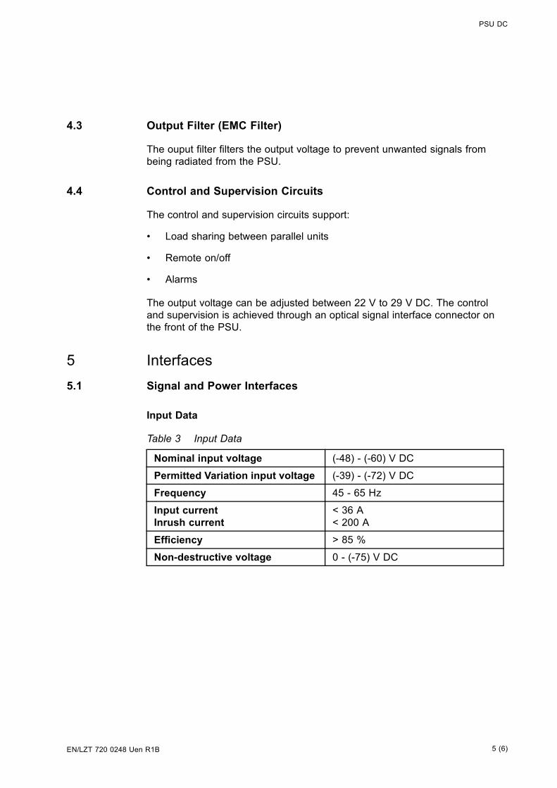
PSU DC
4.3 Output Filter (EMC Filter)
The ouput filter filters the output voltage to prevent unwanted signals frombeing radiated from the PSU.
4.4 Control and Supervision Circuits
The control and supervision circuits support:
• Load sharing between parallel units
• Remote on/off
• Alarms
The output voltage can be adjusted between 22 V to 29 V DC. The controland supervision is achieved through an optical signal interface connector onthe front of the PSU.
5 Interfaces5.1 Signal and Power Interfaces
Input Data
Table 3 Input Data
Nominal input voltage (-48) - (-60) V DC
Permitted Variation input voltage (-39) - (-72) V DC
Frequency 45 - 65 Hz
Input currentInrush current
< 36 A< 200 A
Efficiency > 85 %
Non-destructive voltage 0 - (-75) V DC
5 (6)EN/LZT 720 0248 Uen R1B
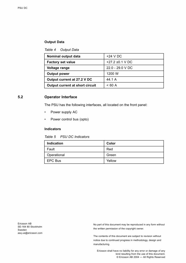
PSU DC
Output Data
Table 4 Output Data
Nominal output data +24 V DC
Factory set value +27.2 ±0.1 V DC
Voltage range 22.0 - 29.0 V DC
Output power 1200 W
Output current at 27.2 V DC 44.1 A
Output current at short circuit < 60 A
5.2 Operator Interface
The PSU has the following interfaces, all located on the front panel:
• Power supply AC
• Power control bus (opto)
Indicators
Table 5 PSU DC Indicators
Indication ColorFault Red
Operational Green
EPC Bus Yellow
Ericsson ABSE-164 80 [email protected]
No part of this document may be reproduced in any form withoutthe written permission of the copyright owner.
The contents of this document are subject to revision without
notice due to continued progress in methodology, design andmanufacturing.
Ericsson shall have no liability for any error or damage of anykind resulting from the use of this document.© Ericsson AB 2004 — All Rights Reserved

EN/LZT 720 0250 Uen R1A
TMA-CM
Tower Mounted Amplifier - Control ModuleUnit Description
The Tower Mounted Amplifier Control Module (TMA-CM), together with the biasinjectors, supply power to the TMA. It also monitors and controls the TMAs.
��������
����� ��
������
������ ��
������� �
���������
E 1 (6)

TMA-CM
Contents1 Product Overview 31.1 Main Functions 3
2 Function Description 4
3 Interface 53.1 Signal and Power Interface 53.2 Operator Interface 5
2 (6) EN/LZT 720 0250 Uen R1A

TMA-CM
1 Product Overview1.1 Main Functions
The TMA-CM has the following functions:
• Supplies power to the TMAs through bias injectors
• Monitors the TMAs
• Controls the TMAs
• Supplies power for up to six TMAs
• Controls TMA (on/off)
• Measures DC and voltage
• Supervises indicators
• Provides short circuit protection
• Supervises cables
3 (6)EN/LZT 720 0250 Uen R1A

TMA-CM
2 Function Description
��������
���������� ��� ��� ��� ��� ��� �
�������
�������
�� ��� ��� ��� ��� ��� �
������������
�� !"���������
�� #�����
������$���
�� !"����
%&&'����
Figure 1 Block Diagram
The TMA-CM supplies up to six TMAs with 15 V DC and maximum 500 mA toeach TMA. The power output is a 15-pole d-sub connector on the front of theTMA-CM. A TMA consumes in general 70 200 mA.
The TMAs can be individually switched on and off by commands from the DXU.
The current and voltage to each TMA is measured, and an alarm is generated ifthe values are outside specified values, indicating that a TMA is not workingproperly. The alarm is transmitted to the DXU on the IOM bus.
The TMA is always used together with its connection cable and connectionplate for bias injectors. The connection plate contains filtering equipment.
An indicator on the front panel is illuminated for each TMA in operational mode.Whether an indicator is illuminated depends also on the actual configuration,see Chapter Radio Configurations, RBS 2106 and RBS 2206.
If the TMA or the feeder cable short-circuites, the TMA-CM limits the current to500 mA.
The power cable to the bias injector is supervised and an alarm is generated ifthe cable is not connected. The alarm is transmitted on the IOM bus.
4 (6) EN/LZT 720 0250 Uen R1A

TMA-CM
3 Interface3.1 Signal and Power Interface
Table 1 Input Data
Nominal input voltage +24 V DC
Input voltage range +20.0 - 29.5 V DC
Non-destructive voltage 0 - +32 V DC
Maximum input power 60 W
Table 2 Output Data
Voltage per output (1 - 6) + 15 v DC(1)
Current per output Maximum 500 mA
(1) Tolerance ±1.0 V at TMA current 0 300 mA. Tolerance ±1.5 V at TMA current 300 500 mA.
3.2 Operator Interface
The TMA-CM has the following external interfaces:
• Power in (+24 V DC)
• IOM bus
• TMA power connector
5 (6)EN/LZT 720 0250 Uen R1A

TMA-CM
Indicators
The TMA-CM has eight indicators on the front panel that shows the status ofeach TMA and the status of the TMA-CM.
The indicators Fault and Operational indicate the status of the TMA-CM only,not the status of the TMAs.
Table 3 Indicators
Indicator ColorFault Red
Operational Green
TMA1 operating Yellow
TMA2 operating Yellow
TMA3 operating Green
TMA4 operating Green
TMA5 operating Green
TMA6 operating Green
Ericsson ABSE-164 80 [email protected]
No part of this document may be reproduced in any form withoutthe written permission of the copyright owner.
The contents of this document are subject to revision without
notice due to continued progress in methodology, design andmanufacturing.
Ericsson shall have no liability for any error or damage of anykind resulting from the use of this document.© Ericsson AB 2004 — All Rights Reserved

EN/LZT 720 0283 Uen R1B
RBS 2000Glossary
This document provides a glossary of terms and abbreviations used inRBS 2000 Customer Product Information (CPI).
E 1 (24)

RBS 2000Glossary
Contents
1 Introduction 3
2 Terms and Abbreviations 3
2 (24) EN/LZT 720 0283 Uen R1B

RBS 2000 Glossary
1 Introduction
This glossary lists abbreviations and acronyms used in texts dealing with RBS2000 cabinets. Some basic terms and acronyms needed for cross-referenceare included in the list.
An arrow ⇒ is used to indicate a reference to another entry in the list.
Where there are several meanings for the same term and the terms are cabinetsize dependent, this is indicated using Macro and Micro where applicable..
The following RBSs are Macro cabinets:
• RBS 2101
• RBS 2102
• RBS 2103
• RBS 2106
• RBS 2202
• RBS 2205
• RBS 2206
The following RBSs are Micro cabinets:
• RBS 2301
• RBS 2302
• RBS 2401
• Maxite
2 Terms and Abbreviations
1–P One-Pair connection with echo cancellation (= twowires)
2–P Two-Pair connection with echo cancellation (= fourwires)
AAU Active Antenna Unit
Abis GSM interface standard defining attributes of thecommunication between the BSC and the BTS.
AC Alternating Current
3 (24)EN/LZT 720 0283 Uen R1B

RBS 2000Glossary
ACB Alarm Collection Board
ACCU Alternating Current Connection Unit
ACCU-CU ACCU Connection Unit
ACCU-DU ACCU Distribution Unit
A/D converter Analog to Digital converter
AFS AMR Full-rate speech
AGW Abis Gateway
AHR AMR Half-rate speech
Air conditioner One version of the climate unit (Active cooler)
AIS Alarm Indication Signal
ALBO Automatic Line Build Out
ALNA Antenna Low Noise Amplifier
ALPU Antenna Lightning Protection Unit
AMR Adaptive Multi-Rate
AO Application Object
ARAE Antenna Related Auxiliary Equipment
ARFCN Absolute Radio Frequency Channel Number
ARP Antenna Reference Point
ARU Active Replaceable Unit
ASIC Application Specific Integrated Circuit
Astra ASIC in the TRU
ASU Antenna Sharing Unit
AT Alphanumeric Terminal
ATRU Adaptive Transceiver Unit
ATSR Air Time Slot Resource
4 (24) EN/LZT 720 0283 Uen R1B

RBS 2000 Glossary
AU Antenna Unit
GSM 900 = CEU + Passive Antenna
GSM 1800/1900 = AAU
BALUN BALance and UNbalance transformer
Batt Battery
BB Battery Box
BBS Battery Back-up System
BCCH Broadcast Control CHannel
Downlink only broadcast channel for broadcast ofgeneral information at a base station, on a base stationbasis.
BCS Block Check Sequence
BDM Battery Distribution Module
The BDM is an IDM with a battery and a local processor.
BER Bit Error Rate
BFF Bit Fault Frequency
BFI Bad Frame Indication
BFU Battery Fuse Unit
Bias injector A unit which injects DC power into the coaxial cableto feed the TMA. Isolates the DC power from the RFsignal fed to the CDU.
Bm Denotes a full-rate traffic channel
BPC Basic Physical Channel
Denotes the air interface transport vehicle formedby repetition of one time slot on one or more radiofrequency channels.
BS Base Station
BSC Base Station Controller
GSM network node for control of one or more BTSs.
5 (24)EN/LZT 720 0283 Uen R1B

RBS 2000Glossary
BSCSim Base Station Controller Simulator
BSS Base Station System
GSM network logical unit comprising one BSC andone or more BTSs.
BTS Base Transceiver Station
GSM network unit operating on a set of radio frequencychannels in one cell.
burst A portion of digital information, the physical content, thatis transferred within the time interval of one time slot.
cabinet The physical housing of a base station
Cascadeconnections
Connection of several cabinets by the PCM cable.Similar to serial connection.
⇒ Cascading
Cascading Connection of several cabinets by the PCM cable.Similar to serial connection.
⇒ Cascade connections
CBCH Cell Broadcast CHannel
This is a downlink only channel used by the GSMdefined SMSCB function.
CCCH Common Control CHannel
Channel combining the following common controlchannels:
• PCH Paging CHannel
• RACH Random Access CHannel
• AGCH Access Grant CHannel
CCU Climate Control Unit
CDU Combining and Distribution Unit
CE Conformité Européenne
cell An area of radio coverage identified by the GSMnetwork by means of the cell identity.
6 (24) EN/LZT 720 0283 Uen R1B

RBS 2000 Glossary
CEU Coverage Extension Unit
CF Central Functions
channel The common term channel denotes the virtualconnection, consisting of physical and logical channels,between BSS and MS, during a call in progress.
⇒ Logical Channel ⇒ Physical Channel
ChannelCombination
A physical channel on an air interface carrying a definedset of logical channels.
Channel group A channel group is a group of dedicated logicalchannels to a specific MS.
CM Macro = Control Module (for TMA)
Micro = Common Mode
CMD Digital Radio Communication Tester
CMRU Central Main Replaceable Unit.
The RBS is physically connected to the Base StationController (BSC) via the CMRU. There is only oneCMRU in each RBS.
Macro: CMRU = DXU
Micro: CMRU = The whole RBS
CNU Combining Network Unit
Compr Compressor
CON LAPD concentrator
LAPD concentration is used to reduce the number ofrequired physical links between the BSC and BTS.
Config Configuration
Co-siting Co-siting is the operation of radio equipment from morethan one mobile telephone system and/or frequency onthe same site sharing common equipment.
CPI Communication and Power Interface
CPI Customer Product Information
7 (24)EN/LZT 720 0283 Uen R1B

RBS 2000Glossary
CPU Central Processing Unit
CRC Cyclic Redundancy Check
CS Coding Scheme
CSA Canadian Standards Association
CSES Consecutive Severely Errored Second
CSU Macro = Channel Service Unit
Micro = Customer Service Unit
CU Combining Unit (RU in CDU_D)
CXU Configuration Switch Unit
Dannie ASIC in the TRU
DB DataBase
DC Direct Current
DCC Digital Cross Connector
DCCH Dedicated Control CHannel
Dedicated control channels carry signalling data.
DCCU DC Connection Unit
ddTMA dual duplex Tower Mounted Amplifier
This type needs only one combined TX/RX feeder fromthe BTS to the TMA. ⇒ dTMA ⇒ rTMA ⇒ TMA ⇒ BTS
DF Distribution Frame
DF Disturbance Frequency
DFU Distribution and Fuse Unit
DIP DIgital Path
The name of the function used for supervision of theconnected PCM lines.
Dixie ASIC in the TRU
DM Degraded Minute
8 (24) EN/LZT 720 0283 Uen R1B

RBS 2000 Glossary
DM Distribution Module
DM Micro = Differential Mode
DMRU Distributed Main Replaceable Unit
If a Main RU is subordinated to the CMRU, it is said tobe distributed.
downlink Signalling direction from the system to the MS.
DP Digital Path
DP Distribution Panel
DPX Duplexer
DS1 Digital Signal level 1 (1544 kbit/s)
DSP Digital Signal Processor
DT Data Transcript
DTE Data Terminal Equipment
DTF Distance To Fault
dTMA duplex TMA
dTMA is similar to the old ALNA except for differentcharacteristics. ⇒ ddTMA ⇒ rTMA ⇒ TMA
dTRU double TRansceiver Unit
DU Distribution Unit (RU in CDU-D)
DUT Device Under Test
DX Direct Exchange
DXB Distribution Switch Board
DXC Digital Cross Connector
DXU Distribution Switch Unit
DXX Ericsson Cellular Transmission System including NMS
E1 Transmission standard, G.703, a 2048 kbit/s PCM link
E-GSM Extended GSM
9 (24)EN/LZT 720 0283 Uen R1B

RBS 2000Glossary
EACU External Alarm Connection Unit
EC1 External Condition Map Class 1
EC2 External Condition Map Class 2
ECU Energy Control Unit
EDGE Enhanced Data rate for Global Evolution
EDGE dTRU EDGE double TRansceiver Unit
⇒ EDGE
EDT Electrical Down Tilt
EEPROM Electrically Erasable Programmable Read-Only Memory
EIRP Effective Isotropic Radiated Power
EMC ElectroMagnetic Compatibility
EMF ElectroMotive Force
EMF ElectroMagnetic Field
EMI Electromagnetic Interference
ENV Environmental
EOC Embedded Operations Channel
EPC Environmental and Power Control
ES Errored Second
ESB External Synchronization Bus
ESD ElectroStatic Discharge
ESF Extended Superframe Format
ESO Ericsson Support Office
ETS European Telecommunication Standard
EXT External
FACCH Fast Associated Control CHannel
Main signalling channel in association with a TCH.
10 (24) EN/LZT 720 0283 Uen R1B

RBS 2000 Glossary
FCC Federal Communications Commission
FCCH Frequency Correction CHannel
FCOMB Filter COMBiner
FCU Fan Control Unit
FDL Facility Data Link
FDU Feeder Duplexer Unit
FER Frame Erasure Ratio
FIU Fan Interface Unit
FS Function Specification
FSC Field Support Centre
FU Filter Unit (RU in CDU-D)
FUd Filter Unit with duplexer (RU in CDU-D)
FXU Future Expansion Unit
G01 MO model for RBS 200
G12 MO model for RBS 2000
G.703 Physical/electrical characteristics of hierarchical digitalinterfaces, as defined by the ITU.
G.704 Synchronous frame structures used at 1544, 6312,2048, 8448 and 44 736 kbit/s, as defined by the ITU.
GPRS General Packet Radio Services
GS General Specification
GSL GPRS Signalling Link
GSM Global System for Mobile communications
International standard for a TDMA digital mobilecommunication system. Originally, GSM was anabbreviation for Group Special Mobile, which is aEuropean mobile telecommunication interest group,established in 1982.
11 (24)EN/LZT 720 0283 Uen R1B

RBS 2000Glossary
GSM 800 GSM system 800 MHz (generic)
GSM 900 GSM system 900 MHz (generic)
GSM 1800 GSM system 1800 MHz (generic)
GSM 1900 GSM system 1900 MHz (generic)
HCE HDSL Central Equipment
HCOMB Hybrid COMBiner
HDLC High level Data Link Control
HDSL High bit rate Digital Subscriber Line
Heat Exchanger A version of the climate unit
HEU Heat Exchanger Unit
HISC Highway Splitter Combiner
HLIN High Level IN
HLOUT High Level OUT
HMS Heat Management System
Hum Humidity
HW HardWare
HWU HardWare Unit
An HWU consists of one or more SEs. An HWU isa functional unit within the RBS. The HWU is eitheractive (equipped with a processor) or passive (withoutprocessor).
I1A Internal Fault Map Class 1A
I1B Internal Fault Map Class 1B
I2A Internal Fault Map Class 2A
IA Immediate Assignment
IC Integrated Circuit
ICMI Initial Codec Mode Indicator
12 (24) EN/LZT 720 0283 Uen R1B

RBS 2000 Glossary
ID IDentification
IDB Installation DataBase
IDM Internal Distribution Module
IEC International Electric Commission
IF Box Interface Box
IMSI International Mobile Subscriber Identity
INIT Initial
INT Internal
IOG Input/Output Group
IOM Internal Operation and Maintenance bus
IR InfraRed
IS Interface Switch
IWD InterWork Description
JTC Joint Technical Committee
LAN Local Area Network
LAPD Link Access Procedures on D-channel
LAPD is the data link layer (layer 2) protocol used forcommunication between the BSC and the BTS on theAbis interface.
Abis layer 2 is sometimes used synonymously withLAPD.
LBO Line Build Out
LED Light Emitting Diode
LLB Line Loop Back
LNA Low Noise Amplifier
Local bus The local bus offers communication between a centralmain RU (DXU) and distributed main RUs (TRU andECU).
13 (24)EN/LZT 720 0283 Uen R1B

RBS 2000Glossary
Local mode When the RU is in Local mode, it is not communicatingwith the BSC.
Local/Remoteswitch
A switch used by the operator to order the RU to enterLocal or Remote mode.
LOF Loss Of Frame
Logical Channel A logical channel represents a specified portion of theinformation carrying capacity of a physical channel.
GSM defines two major categories of logical channels:
• TCHs – Traffic CHannels, for speech or user data
• CCHs – Control CHannels, for control signalling
⇒ Physical Channel ⇒ Channel Combination
Logical RU A unit which can be referred to, but is not a singlephysical unit. There are three different kinds of logicalRUs:
• Antennas
• Buses
• Environment
LOS Loss Of Signal
LVD Low Voltage Directive
LVF Low Voltage Filter
MAC Medium Access Controller
MADT Mean Accumulated DownTime
magazine A magazine is a reserved space in the cabinet, whichmay hold one or more RUs.
Main RU Contains one or more processors, to which softwarecan be downloaded from the BSC. A Main RU is eitherCentral (CMRU) or Distributed (DMRU). A Main RUmay or may not have a direct signalling link to the BSC.
Main RU A main replaceable unit is a replaceable unit thatcontains one or more processors, to which software canbe downloaded from the BSC.
14 (24) EN/LZT 720 0283 Uen R1B

RBS 2000 Glossary
MCB MultiCasting Box
MHS Modification Handling System
Ericsson trouble report database
MMI Man-Machine Interface
MO Managed Object
MR Measurement Receiver
MRT Mean Repair Time
MS Mobile Station
MSC Mobile services Switching Centre
GSM network unit for switching, routing and controllingcalls to and from the Public Switched TelephoneNetwork (PSTN) and other networks.
MSTP Mobile Station Test Point
MTBF Mean Time Between Failure
MTBCF Mean Time Between Catastrophe Failure
Multidrop Two or more RBSs connected in a chain to the sametransmission system. All the relevant time slots aredropped out by each RBS. (This function is sometimescalled cascading.)
NCS National Colour System
NEBS Network Equipment Building System
NMS Ericsson Network Management System in DXX
Nominal Power The nominal power is the power level defined whenconfiguring the transceiver.
N terminal Neutral terminal in an AC mains connection
NTU Network Terminating Unit
OL/UL Overlaid/Underlaid
15 (24)EN/LZT 720 0283 Uen R1B

RBS 2000Glossary
O&M Operation and Maintenance
General term for activities such as configuration,utilization of channels (frequency bands), cellplanning, system supervision, hardware and softwaremaintenance, subscriber administration, and so on.
OMC Operation and Maintenance Centre
OML Operation and Maintenance Link
Layer 2 communication link for operation andmaintenance services on Abis.
OMT Operation and Maintenance Terminal
The OMT is a terminal that supports functions forhandling the RBS on site. The terminal can be aportable PC.
Operation Operation is the normal, everyday running of the RBSwith full functions.
OPI OPerational Instructions
OVP OverVoltage Protection
OXU Space for Optional Expansion
P-GSM Primary GSM
PA Power Amplifier
PAM Power Amplifier Module
Passive RU A passive replaceable unit has a very low level ofintelligence and is independent of the processor system.
PBA Printed Board Assembly
PBC Power and Battery Cabinet
PC Personal Computer
PCAT Product CATalogue
A web-based ordering system on Ericsson’s Intranet.
PCB Printed Circuit Board
16 (24) EN/LZT 720 0283 Uen R1B

RBS 2000 Glossary
PCH Paging CHannel
Downlink only subchannel of CCCH for system pagingof MSs.
⇒ CCCH
PCM Pulse Code Modulation
PCU Packet Control Unit
PDCH Packet Data Channel
PE terminal Protective Earth terminal in an AC mains connection
PFWD Power Forward
Physical Channel An air interface physical channel carries one ormore logical channels. A physical channel uses acombination of frequency and time division multiplexingand is defined as a sequence of radio frequencychannels and time slots.
⇒ TDMA frame ⇒ Logical channel
PIN Personal Identification Number
PLB Payload Loop Back
PLMN Public Land Mobile Network
A network, established and operated by anadministration or its licensed operator(s), for the specificpurpose of providing land mobile communicationservices to the public. It provides communicationpossibilities for mobile users. For communicationbetween mobile and fixed users, interworking with afixed network is necessary.
PPE Personal Protective Equipment
PREFL Power Reflected
PSA Power Supply Adapter
PSTN Public Switch Telephone Network
PSU Power Supply Unit
PWU Power Unit
17 (24)EN/LZT 720 0283 Uen R1B

RBS 2000Glossary
RACH Random Access CHannel
Uplink only subchannel of CCCH for MS request forallocation of a dedicated channel.
⇒ CCCH
RAI Remote Alarm Indication
RAM Random Access Memory
RBER Radio Bit Error Ratio
RBS Radio Base Station
All equipment forming one or more Ericsson basestation.
⇒ BTS
RCB Radio Connection Box
RD Receive Data
Remote mode When the RU is in RU Remote mode, a link isestablished between the BSC and the Central MainRU (CMRU).
RF Radio Frequency
RFCH Radio Frequency CHannel
A radio frequency carrier with its associated bandwidth.
RFTL Radio Frequency Test Loop
RLC Radio Link Control
RLC Repair Logistic Centre
RSL Radio Signalling Link
R-state Release state
RS232 American standard for term/MODEM interconnection.
rTMA Receiver TMA
rTMA has no duplexers. It is used for amplification ofthe RX signal. ⇒ ddTMA ⇒ dTMA ⇒ TMA
18 (24) EN/LZT 720 0283 Uen R1B

RBS 2000 Glossary
RTN Return
RU Replaceable Unit
An RU consists of one or more HWUs. An RU may bereplaced by another RU of the same type. The RU isthe smallest unit that can be handled on site.
RX Receiver
RX1 Receiver antenna branch 1
RX2 Receiver antenna branch 2
RXA Receiver antenna branch A
RXB Receiver antenna branch B
RXD Receiver Divider
RXDA Receiver Divider Amplifier
RXDP Receiver Distribution Plane
RXLEV Measure of signal strength as defined inGSM:05.08:8.1.4
RXQUAL Measure of signal quality as defined in GSM:05.08:8.2.4
SACCH Slow Associated Control CHannel
SCH Synchronization CHannel
SDCCH Stand alone Dedicated Control CHannel
Main dedicated signalling channel on the air interface,mainly used for call locating and establishment.
SCU Switching and Combining Unit
SE Supervised Entity
SES Severely Errored Second
SF Slip Frequency
SID Silence Descriptor
SIG Signalling
SIM Subscriber Identity Module
19 (24)EN/LZT 720 0283 Uen R1B

RBS 2000Glossary
SIR Small Indoor RBS
SMS Short Message Service (point to point)
A short message, up to 160 alphanumeric characterslong, can be sent to or from an MS (point to point).
SO Service Object
SS Swedish Standard
Sub-RU A sub-replaceable unit is always connected to asuperior Main RU. This connection is used for examplefor retrieval of the RU identity. A sub-RU normally doesnot have a processor. Note that an RU with a processor,which cannot be loaded, is classified as a sub-RU.
SVS System Voltage Sensor
SW SoftWare
SWR Standing Wave Ratio
SYNC Synchronous
T1 Transmission standard, G.703, a 1544 kbit/s PCM link
TA Timing Advance
A signal sent by the BTS to the MS which the MS usesto advance its timing of transmissions to the BTS tocompensate for propagation delay.
TC Transaction Capabilities
TCB Transceiver Control Board
TCH Traffic CHannel
The traffic channels carry either encoded speech oruser data.
TCH/F Traffic Channel, Full-rate
TCH/H Traffic Channel, Half-rate
TCC Transmission Coherent Combining
TCH SIG Traffic CHannel Signalling
20 (24) EN/LZT 720 0283 Uen R1B

RBS 2000 Glossary
TD Transmit Data
TDMA Time Division Multiple Access
Multiplexing of several channels in a common frequencyband. Each channel is assigned a certain time division,a time slot.
TDMA frame GSM air interface time frame comprising eight timeslots.
TEI Terminal Endpoint Identifier
TEI is an identification code carried by a LAPD frame asa terminal connection endpoint within a Service AccessPoint (SAP).
TEMS TEst Mobile Station
TF Timing Function
TG Transceiver Group
Timing bus The timing bus carries air timing information from thetiming unit in the DXU to the TRUs.
TLS Terrestrial Link Supervision
TM Transport Module
The Transport module is non-RBS equipment belongingto the transport network.
TMA Tower Mounted Amplifier
There are three types of TMAs: dTMA, rTMA andddTMA. ⇒ dTMA ⇒ rTMA ⇒ ddTMA
TMA-CM Tower Mounted Amplifier – Control Module
TN Time slot Number
TN O&M Transport Network Operation and Maintenance (ingeneral)
Tora ASIC in the TRU
21 (24)EN/LZT 720 0283 Uen R1B

RBS 2000Glossary
TRA Transcoder Rate Adapter
The TRA Unit (TRAU) in BSC performs transcodingof speech information and rate adaptation of datainformation.
Tracy ASIC in the TRU
TRS Transceiver System
TRU Transceiver Unit
TRX Transceiver (combined transmitter and receiver)
TRXC Transceiver Controller
TS Time Slot
A 0.577 ms period (TDMA frame subunit) correspondingto 156.25 raw bits of information. The eight time slots ofeach TDMA frame are numbered 0...7.
TT Total Time
TU Timing Unit
TX Transmitter
TXA Transmitter Antenna A
TXB Transmitter Antenna B
TXBP Transmitter BandPass filter
TXU Radio Transmitter Unit
UAS Unavailable Seconds
UAST UnAvailable STate supervision
UL Underwriter Laboratories
uplink Signalling direction from the MS to the system.
UPS Uninterrupted Power Supply
VCO Voltage Controlled Oscillator
VSWR Voltage Standing Wave Ratio RF signal measure. Thequotient between transmitted and reflected voltage.
22 (24) EN/LZT 720 0283 Uen R1B

RBS 2000 Glossary
X bus The X bus carries transmit air data frames betweentransceivers.
Y link The interface between the DXU and each DSP Systemin core based TRUs.
23 (24)EN/LZT 720 0283 Uen R1B

RBS 2000Glossary
Ericsson ABSE-164 80 [email protected]
The contents of this document are subject to revision withoutnotice due to continued progress in methodology, design and
manufacturing.Ericsson shall have no liability for any error or damages of any
kind resulting from the use of this document.© Ericsson 2002 — All Rights Reserved
24 (24) EN/LZT 720 0283 Uen R1B