pulse transformer design
TRANSCRIPT

7/26/2019 Pulse Transformer Design
http://slidepdf.com/reader/full/pulse-transformer-design 1/7
s the name prefaces the operating frequency of these transformers would be typically around few
hundred kilo hertz. The main significance of these transformers is in “Switched Mode Power
Supplies”. The main conceptual idea of Switched Mode Power Supply is that it is using energyefficient deices to transfer!conert the Power "#.$.!%.$& from the source to the sink!load. 'ne
such energy efficient deice is (igh )requency Pulse Transformer. The switching frequency of
these SMPSs "Switched Mode Power Supply& system will be ery high as a concern it reducesthe size of magnetics "like transformer and inductor& and and it reduces the ripple and so on. *n
later sessions we will be discussing about complete design of (igh frequency transformer from
fundamentals for a %$+%$ conerter as an application.
High Frequency Transformer Designing
There are two main core requirements of (igh )requency Transformer in the SMPS system. ,.
To match the oltage leels of Source and the -oad . To proide electrical isolation between the
power circuits. The schematic diagram of the Transformer is as shown below/
0e can basically categorize the transformer circuitry as
“1lectrical $ircuit” and “Magnetic $ircuit”.
The electrical equialent circuit of a transformer is shown below/
0here primary electric circuit is
represented with a current source representing the relation
and secondary electrical circuit is represented with a oltage source representing the relation
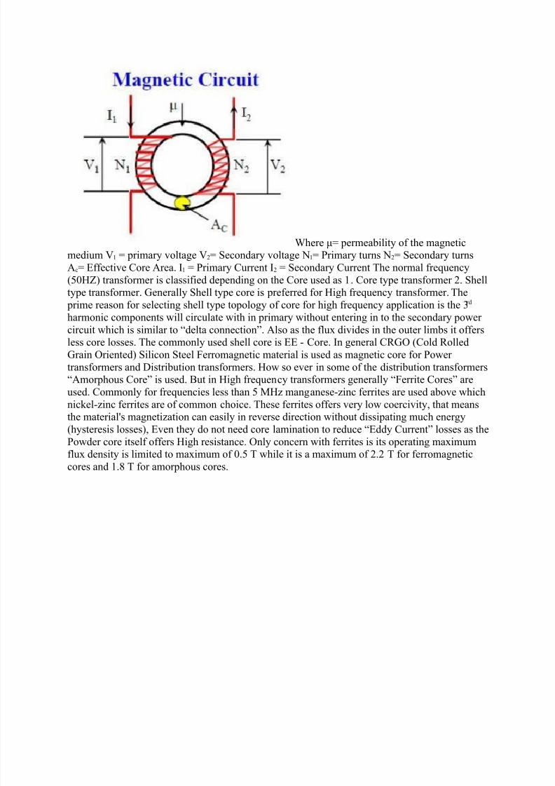
The magnetic equialent circuit is shown taking a Toroid$ore as magnetic medium for common flu2/
7/26/2019 Pulse Transformer Design
http://slidepdf.com/reader/full/pulse-transformer-design 2/7
0here 34 permeability of the magneticmedium 5, 4 primary oltage 54 Secondary oltage 6,4 Primary turns 64 Secondary turns
#c4 1ffectie $ore #rea. *, 4 Primary $urrent * 4 Secondary $urrent The normal frequency
"78(9& transformer is classified depending on the $ore used as ,. $ore type transformer . Shelltype transformer. :enerally Shell type core is preferred for (igh frequency transformer. The
prime reason for selecting shell type topology of core for high frequency application is the ;rd
harmonic components will circulate with in primary without entering in to the secondary power
circuit which is similar to “delta connection”. #lso as the flu2 diides in the outer limbs it offersless core losses. The commonly used shell core is 11 + $ore. *n general $<:' "$old <olled
:rain 'riented& Silicon Steel )erromagnetic material is used as magnetic core for Power
transformers and %istribution transformers. (ow so eer in some of the distribution transformers“#morphous $ore” is used. =ut in (igh frequency transformers generally “)errite $ores” are
used. $ommonly for frequencies less than 7 M(z manganese+zinc ferrites are used aboe which
nickel+zinc ferrites are of common choice. These ferrites offers ery low coerciity/ that means
the material>s magnetization can easily in reerse direction without dissipating much energy"hysteresis losses&/ 1en they do not need core lamination to reduce “1ddy $urrent” losses as the
Powder core itself offers (igh resistance. 'nly concern with ferrites is its operating ma2imumflu2 density is limited to ma2imum of 8.7 T while it is a ma2imum of . T for ferromagnetic
cores and ,.? T for amorphous cores.
7/26/2019 Pulse Transformer Design
http://slidepdf.com/reader/full/pulse-transformer-design 3/7
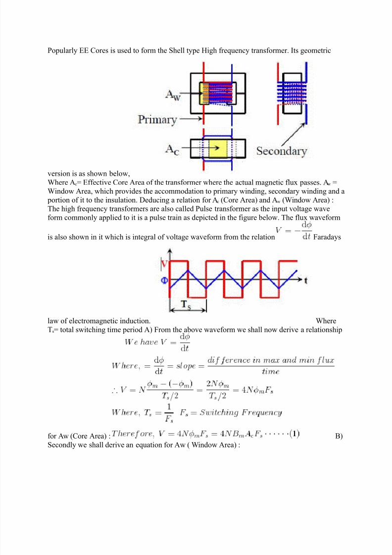
Popularly 11 $ores is used to form the Shell type (igh frequency transformer. *ts geometric
ersion is as shown below/
0here #c4 1ffectie $ore #rea of the transformer where the actual magnetic flu2 passes. #w 4
0indow #rea/ which proides the accommodation to primary winding/ secondary winding and a portion of it to the insulation. %educing a relation for #c "$ore #rea& and #w "0indow #rea& @The high frequency transformers are also called Pulse transformer as the input oltage wae
form commonly applied to it is a pulse train as depicted in the figure below. The flu2 waeform
is also shown in it which is integral of oltage waeform from the relation )aradays
law of electromagnetic induction. 0here
Ts4 total switching time period #& )rom the aboe waeform we shall now derie a relationship
for #w "$ore #rea& @ =&
Secondly we shall derie an equation for #w " 0indow #rea& @
7/26/2019 Pulse Transformer Design
http://slidepdf.com/reader/full/pulse-transformer-design 4/7
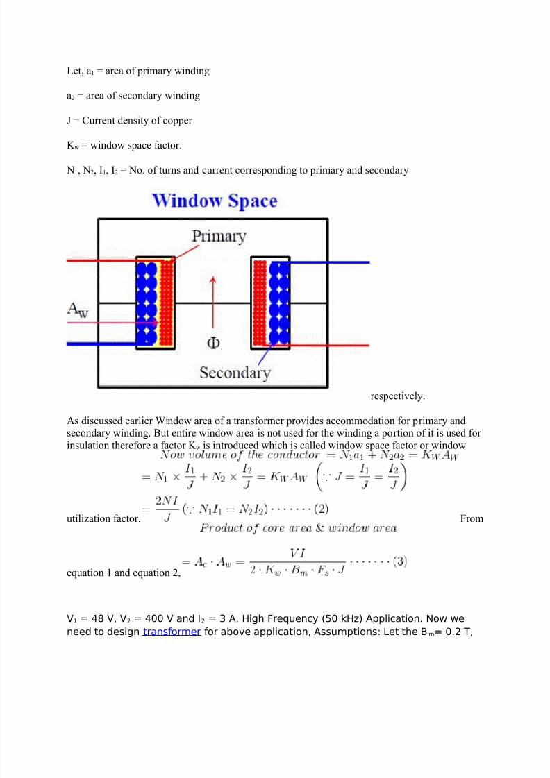
-et/ a, 4 area of primary winding
a 4 area of secondary winding
A 4 $urrent density of copper
B w 4 window space factor.
6,/ 6/ *,/ * 4 6o. of turns and current corresponding to primary and secondary
respectiely.
#s discussed earlier 0indow area of a transformer proides accommodation for primary andsecondary winding. =ut entire window area is not used for the winding a portion of it is used for
insulation therefore a factor B w is introduced which is called window space factor or window
utilization factor. )rom
equation , and equation /
V1 = 48 V, V2 = 400 V and I2 = 3 A. High Frequency (50 kHz A!!"ica#i$n. %$& &e
need #$ de'ign #ran'$r)er $r a*$+e a!!"ica#i$n, A''u)!#i$n' -e# #he )= 0.2 /,
7/26/2019 Pulse Transformer Design
http://slidepdf.com/reader/full/pulse-transformer-design 5/7
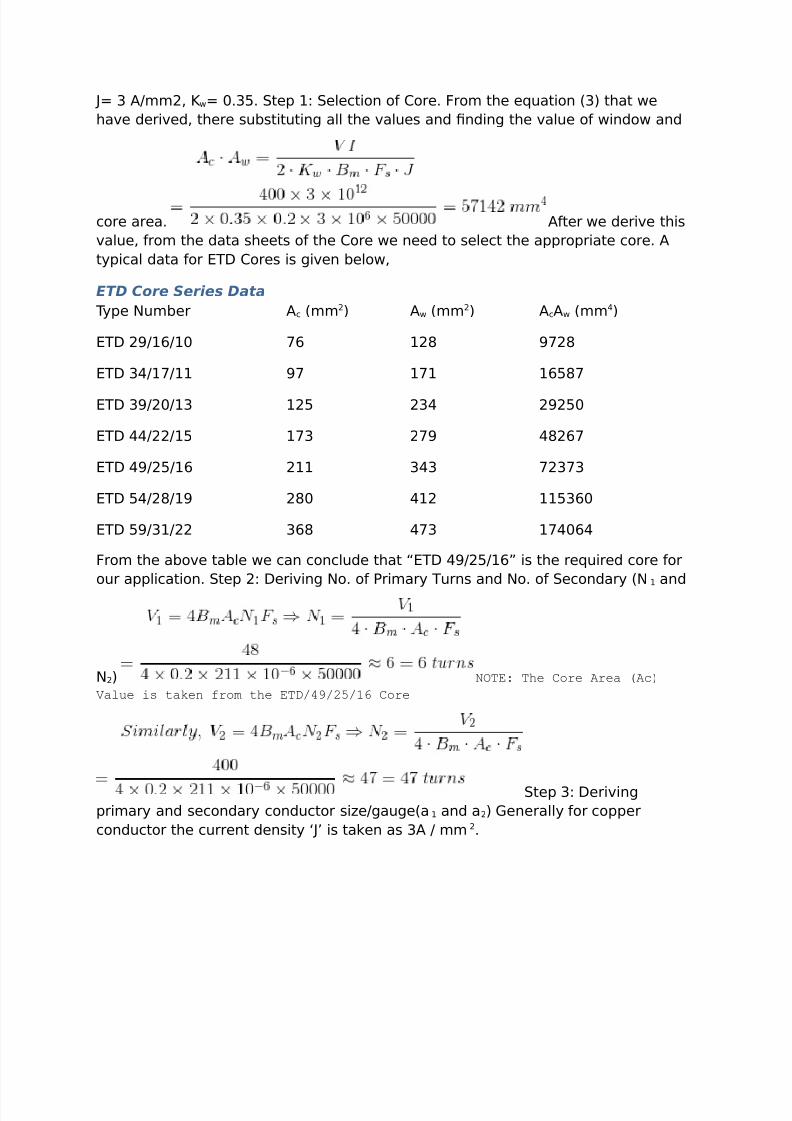
= 3 A))2, &= 0.35. #e! 1 e"ec#i$n $ $re. Fr$) #he equa#i$n (3 #ha# &e
ha+e deri+ed, #here 'u*'#i#u#ing a"" #he +a"ue' and nding #he +a"ue $ &ind$& and
c$re area. A#er &e deri+e #hi'
+a"ue, r$) #he da#a 'hee#' $ #he $re &e need #$ 'e"ec# #he a!!r$!ria#e c$re. A
#y!ica" da#a $r 6/7 $re' i' gi+en *e"$&,
ETD Core Series Data
/y!e %u)*er Ac ())2 A& ())2 AcA& ())4
6/7 21910 :9 128 :28
6/7 341:11 : 1:1 1958:
6/7 32013 125 234 2250
6/7 442215 1:3 2: 4829:
6/7 42519 211 343 :23:3
6/7 54281 280 412 115390
6/7 53122 398 4:3 1:4094
Fr$) #he a*$+e #a*"e &e can c$nc"ude #ha# ;6/7 42519< i' #he required c$re $r
$ur a!!"ica#i$n. #e! 2 7eri+ing %$. $ ri)ary /urn' and %$. $ ec$ndary (%1 and
%2 NOTE: The Core Area (Ac)
Value is taken from the ETD/49/2/!" Core
#e! 3 7eri+ing
!ri)ary and 'ec$ndary c$nduc#$r 'izegauge(a1 and a2 >enera""y $r c$!!er
c$nduc#$r #he curren# den'i#y ?@ i' #aken a' 3A ))2.

7/26/2019 Pulse Transformer Design
http://slidepdf.com/reader/full/pulse-transformer-design 6/7
#e! 4 7eri+ing !ri)ary
re'i'#ance' and 'ec$ndary re'i'#ance'. nce $n ca"cu"a#ing #he )ean "eng#h $ #he
#urn r$) #he ge$)e#ry $ 6/742519 c$re #he re'i'#ance i' deri+ed r$)
$r)u"ae, F$r 6/7 42519
c$re )ean "eng#h $ a #urn = 83 )) ri)ary Be'i'#ance = 10 CD, ec$ndary
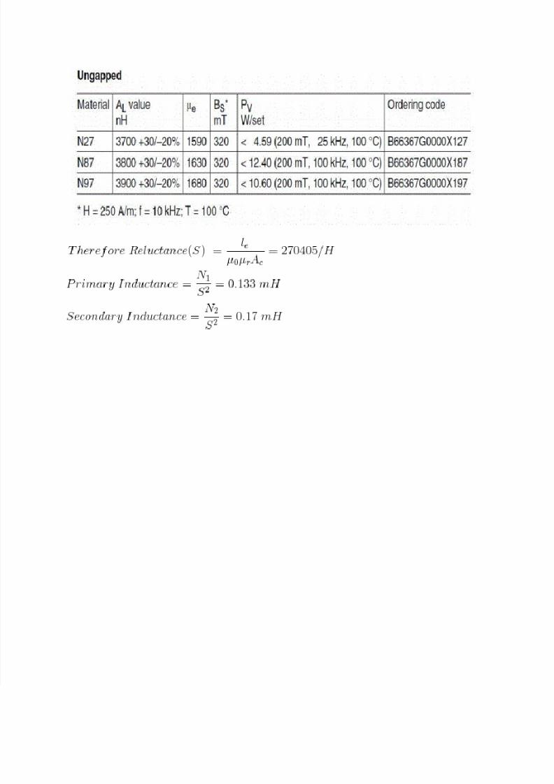
re'i'#ance = 92 CD #e! 5 7eri+ing !ri)ary induc#ance and 'ec$ndary
induc#ance. %$#e /he +a"ue $ ?"e@
E ?Ac@ i' #aken r$) #he c$re )agne#ic charac#eri'#ic' a' 'h$&n in #he *e"$& $r
6/742519 $re. /he +a"ue $ ?Cr Ce@ i' #aken r$) c$re )a#eria" charac#eri'#ic'.
F$r in'#ance "e# #he c$re )a#eria" i' ;unga!!ed %2: )a#eria"<. /he da#a $r 6/7
42519 $re i' 'h$&n *e"$&.
7/26/2019 Pulse Transformer Design
http://slidepdf.com/reader/full/pulse-transformer-design 7/7