transformer design report
TRANSCRIPT

8/3/2019 Transformer Design Report
http://slidepdf.com/reader/full/transformer-design-report 1/14
DESIGN OF SINGLE-
PHASE TRANSFORMER
BY: KUNTAL MONDAL.
Co-worker: MANAS KUMAR MANDAL.
Dept. of Electrical Engg, 3rd Year,Jadavpur University.

8/3/2019 Transformer Design Report
http://slidepdf.com/reader/full/transformer-design-report 2/14
# SPECIFICATION:
1.5 K VA, 230/110 V, Sinewave 50 Hz, air-cooled, plain tank, ambient 40ºC, temperature rise 50ºC.
#STEP-1: (Calculation of primary and secondary
KVA) V P IP =V S IS =KVA.
IS =1.5×10³/110 A=13.16 A.
IP = V s Is /V P =(110×13.6)/220 A=6.18 A.
Actual value of primary current, IP ’=1.02× IP ; for the no-load current
=1.02×6.18 A=6.93 A.
Primary KVA= V P IP ’= 1.526KVA.Secondary KVA=1.5 KVA.
#STEP-2: (Calculation of volts per
turn)Volts per turn, Et =K×Q½.
Where, Q=average of total KVA of secondary & primary =(1.5+1.526)/2 KVA=1.513 KVA.
K=emperical constant=1.1 for shell type=0.8 for core type.
We choose core type construction.
→ Et =0.8×1.513½ =0.98
#STEP-3: (Net iron area) Net iron area, Ai =Φm /Bm =(Et ×10 )/(4.44×f×B m ) cm².
Factor 4.44→sinewave.4.0→squarewave.
The value of Bm depends on core material.We choose freshCRGO as core material. Bm =1.5 Wb/m².
→ Ai =(0.98×10 )/(4.44×50×1.5) cm²
2
8/3/2019 Transformer Design Report
http://slidepdf.com/reader/full/transformer-design-report 3/14
=29.43 cm².
3
8/3/2019 Transformer Design Report
http://slidepdf.com/reader/full/transformer-design-report 4/14
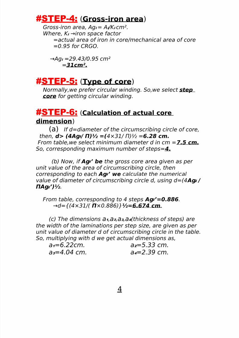
#STEP-4: (Gross-iron area)Gross-iron area, Agi = Ai /K i cm².Where, K i →iron space factor
=actual area of iron in core/mechanical area of core=0.95 for CRGO.
→Agi =29.43/0.95 cm²=31cm².
#STEP-5: (Type of core)Normally,we prefer circular winding. So,we select stepcore for getting circular winding.
#STEP-6: (Calculation of actual core
dimension)
(a) If d=diameter of the circumscribing circle of core,
then, d> (4Agi / Π)½ =( 4×31/ Π)½ =6.28 cm.From table,we select minimum diameter d in cm =7.5 cm.
So, corresponding maximum number of steps= 4.
(b) Now, if Agi’ be the gross core area given as per unit value of the area of circumscribing circle, thencorresponding to each Agi’ we calculate the numericalvalue of diameter of circumscribing circle d, using d=(4 Agi / ΠAgi’)½.
From table, corresponding to 4 steps Agi’=0.886. →d={(4×31/( Π×0.886)}½=6.674 cm.
(c) The dimensions a1 ,a2 ,a3 ,a4 (thickness of steps) arethe width of the laminations per step size, are given as per unit value of diameter d of circumscribing circle in the table.
So, multiplying with d we get actual dimensions as,a1 =6.22cm. a2 =5.33 cm.a3 =4.04 cm. a4 =2.39 cm.
4

8/3/2019 Transformer Design Report
http://slidepdf.com/reader/full/transformer-design-report 5/14
#STEP-7:From the new sectional dimensions of core, we
calculate the resulting gross-core area Agi using geometry as shown:
K 1 =(d²-a1 ²)½=2.42 cm.
K 2 =(d²-a2 ²)½ =4.056 cm.
K 3 =(d²-a3 ²)½ =5.31 cm.
K 4 =(d²-a4 ²)½ =6.231 cm..
Agi( new )= [a1 K 1 +a2 (K 2 -K 1 )+a3 (K 3 -K 2 )+ a4 (K 4 -K 3 )]
=[6.22×2.24+5.3×1.636+4.04×1.254+2.39×0.92
1] cm² = 31cm².
5
8/3/2019 Transformer Design Report
http://slidepdf.com/reader/full/transformer-design-report 6/14
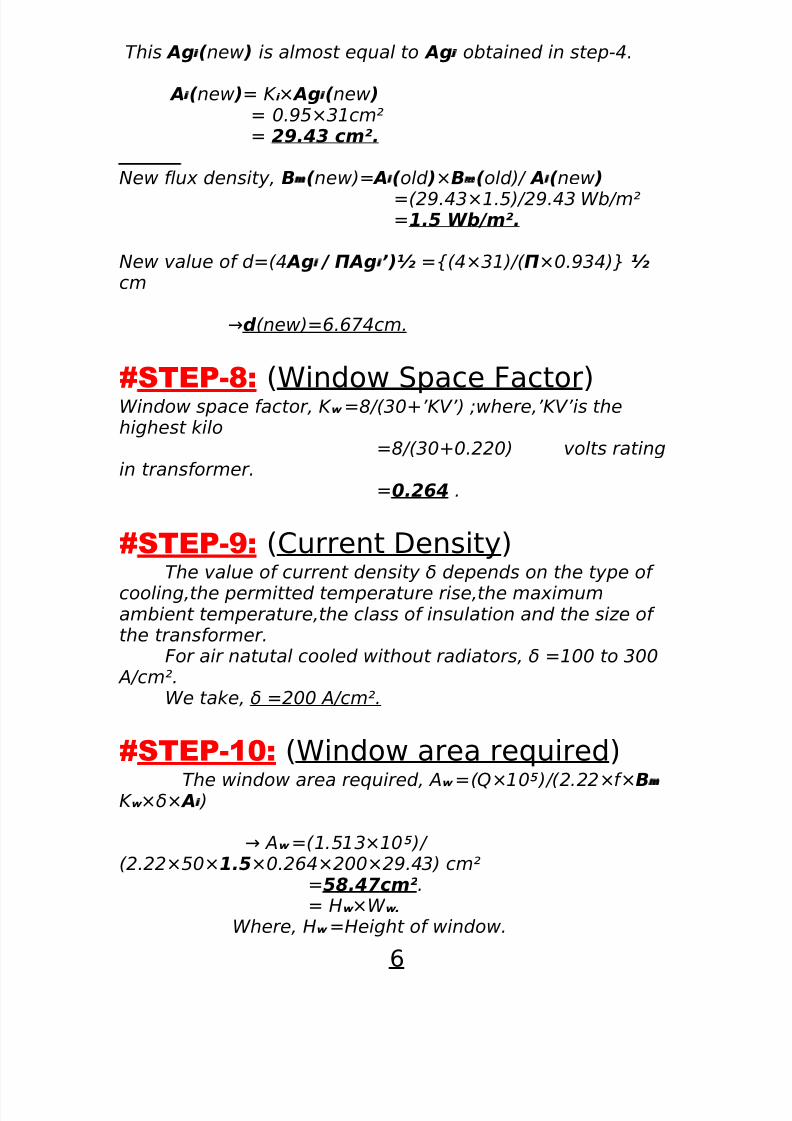
This Agi( new ) is almost equal to Agi obtained in step-4.
Ai( new )= K i × Agi( new )= 0.95×31cm²= 29.43 cm².
New flux density, Bm( new)= Ai( old )×Bm( old)/ Ai( new )
=(29.43×1.5)/29.43 Wb/m²=1.5 Wb/m².
New value of d=(4 Agi / ΠAgi’)½ ={(4×31)/( Π×0.934)} ½cm
→d (new)=6.674cm.
#STEP-8:
(Window Space Factor)Window space factor, K w =8/(30+’KV’) ;where,’KV’is thehighest kilo
=8/(30+0.220) volts ratingin transformer.
=0.264 .
#STEP-9: (Current Density)The value of current density δ depends on the type of
cooling,the permitted temperature rise,the maximumambient temperature,the class of insulation and the size of the transformer.
For air natutal cooled without radiators, δ =100 to 300 A/cm².
We take, δ =200 A/cm².
#STEP-10: (Window area required)
The window area required, Aw =(Q×10 )/(2.22×f×
Bm
K w ×δ× Ai )
→ Aw =(1.513×10 )/
(2.22×50×1.5×0.264×200×29.43) cm²=58.47cm².= Hw ×W w.
Where, Hw =Height of window.
6
8/3/2019 Transformer Design Report
http://slidepdf.com/reader/full/transformer-design-report 7/14
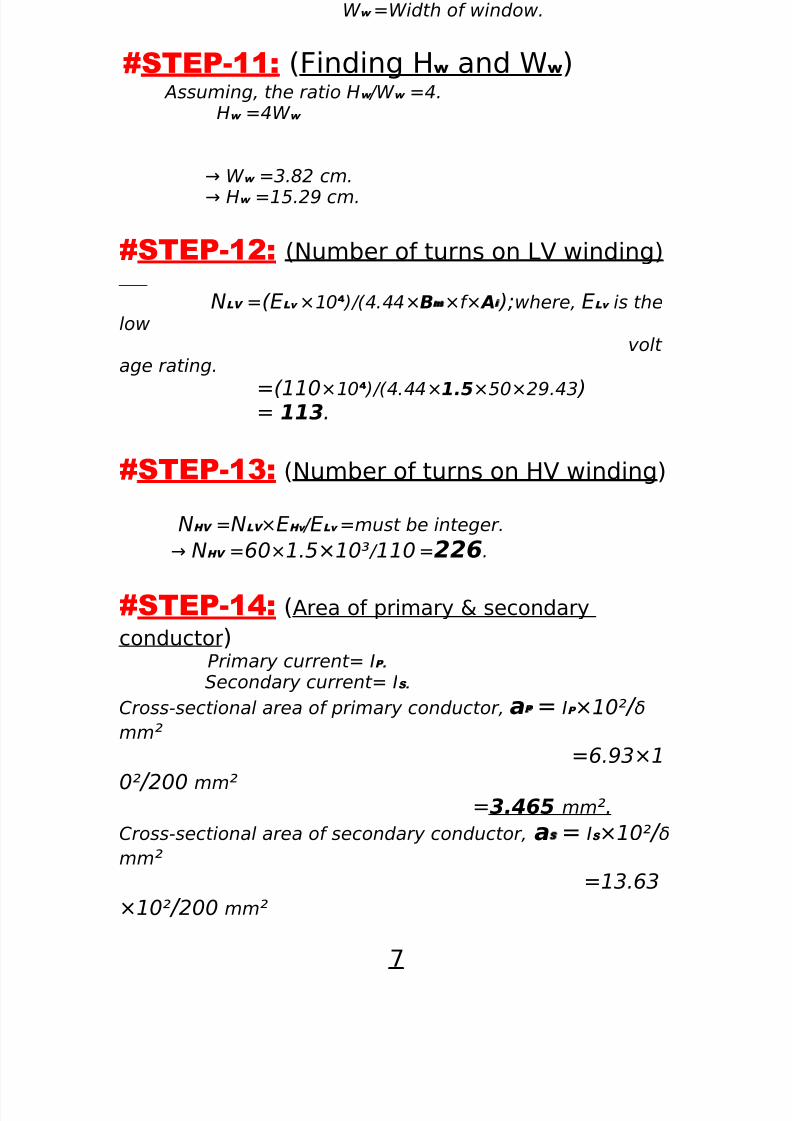
W w =Width of window.
#STEP-11: (Finding H w and W w )Assuming, the ratio Hw /W w =4.
Hw =4W w
→ W w =3.82 cm.
→ Hw =15.29 cm.
#STEP-12: (Number of turns on LV winding)
NLV =(ELv ×10 )/(4.44× Bm×f× Ai );where, ELv is thelow
volt age rating.
=(110×10 )/(4.44× 1.5×50×29.43 )= 113.
#STEP-13: (Number of turns on HV winding)
NHV =NLV ×EHv / ELv =must be integer.
→ NHV =60×1.5×10³ / 110 =226.
#STEP-14: (Area of primary & secondary
conductor) Primary current= IP.
Secondary current= IS.
Cross-sectional area of primary conductor, aP = IP ×10² / δmm² =6.93×1
0² / 200 mm² =3.465 mm ².
Cross-sectional area of secondary conductor, aS = IS ×10² / δmm²
=13.63
×10² / 200 mm²
7

8/3/2019 Transformer Design Report
http://slidepdf.com/reader/full/transformer-design-report 8/14
=6.815mm ².
#STEP-15: (Selection of conductor)We use round enamel coated copper conductor.
SWG Bare copper Bare copper Overall Dia.(mm) for
area(mm ² ) Dia.(mm) syn.Enamel
14 3.243 2.0322.15211 6.818 2.943.086
8

8/3/2019 Transformer Design Report
http://slidepdf.com/reader/full/transformer-design-report 9/14
#STEP-16: (Coil ratings)The transformer is core type.then there will be two
identical coils. one on each limb. hence, each coil will consist of half the primary and half the secondary winding. the two
half primary winding on each coil are connected in series.hence each is rated half the voltage and current.
#STEP-17: (Which winding is to be started
first)We place the HV (primary) windings on the outside per
limb to reduce insulation cost.
#STEP-18: (calculation of dimensions of
former)The inner windings are to be supported on a ‘former’ or ‘bobbin’ when being wound.
#length or height of the ‘former’ or ‘bobbin’ = (Hw - 0.5)cm
= (15.29 –0.5) cm
= 14.79cm.
#the thickness t b of the ‘former’ or ‘bobbin’= (2+0.5 ’KV’)mm.
Where, ‘KV’ is the numerical value of the kilo-volts ratingof the inner winding with respect to earth.
t b = (2+0.5×0.110) mm=2.055 mm.
# c/s dimensions of the ‘former’ or ‘bobbin’:In case of circular winding:
•Inner diameter of the ‘former’:
Di = (d+0.5) cm ; d→dia. of core circumscribingcircle.
= (6.674 + 0.5) cm= 7.174cm.
9
8/3/2019 Transformer Design Report
http://slidepdf.com/reader/full/transformer-design-report 10/14
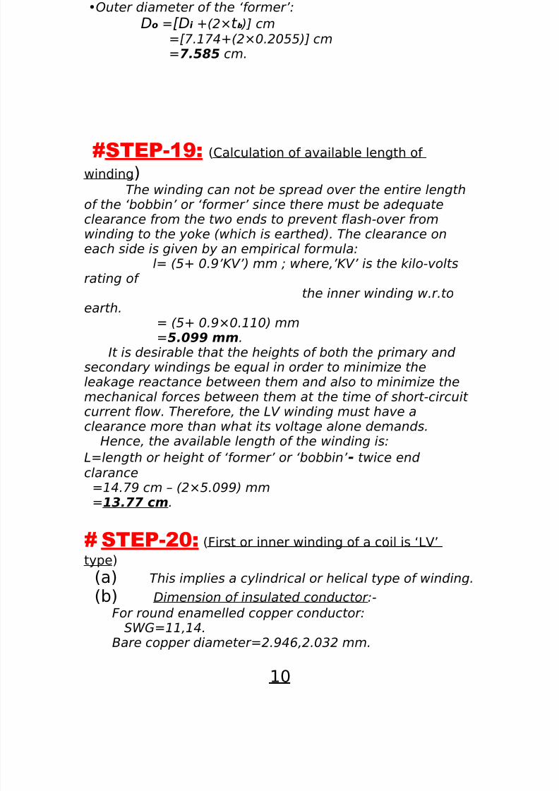
•Outer diameter of the ‘former’:
Do =[Di +(2×t b )] cm=[7.174+(2×0.2055)] cm=7.585 cm.
#STEP-19: (Calculation of available length of
winding) The winding can not be spread over the entire lengthof the ‘bobbin’ or ‘former’ since there must be adequateclearance from the two ends to prevent flash-over fromwinding to the yoke (which is earthed). The clearance oneach side is given by an empirical formula:
l= (5+ 0.9’KV’) mm ; where,’KV’ is the kilo-volts
rating of the inner winding w.r.to
earth.= (5+ 0.9×0.110) mm=5.099 mm.
It is desirable that the heights of both the primary and secondary windings be equal in order to minimize theleakage reactance between them and also to minimize themechanical forces between them at the time of short-circuit
current flow. Therefore, the LV winding must have aclearance more than what its voltage alone demands.Hence, the available length of the winding is:
L=length or height of ‘former’ or ‘bobbin’ - twice end clarance
=14.79 cm – (2×5.099) mm=13.77 cm.
# STEP-20: (First or inner winding of a coil is ‘LV’
type)
(a) This implies a cylindrical or helical type of winding.
(b) Dimension of insulated conductor:-
For round enamelled copper conductor:SWG=11,14.
Bare copper diameter=2.946,2.032 mm.
10
8/3/2019 Transformer Design Report
http://slidepdf.com/reader/full/transformer-design-report 11/14
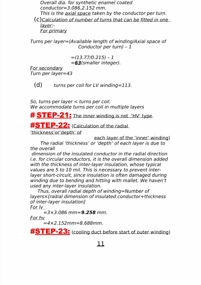
Overall dia. for synthetic enamel coated conductor=3.086,2.152 mm.This is the axial space taken by the conductor per turn.
(c)Calculation of number of turns that can be fitted in one
layer:-For primary
Turns per layer=(Available length of winding/Axial space of Conductor per turn) – 1
=(13.77/0.215) – 1=63(smaller integer).
For secondary Turn per layer=43
(d) turns per coil for LV winding=113.
So, turns per layer < turns per coil.We accommodate turns per coil in multiple layers
# STEP-21: The inner winding is not ‘HV’ type.
#STEP-22: (Calculation of the radial
‘thickness’or’depth’ of each layer of the ‘inner’ winding)
The radial ‘thickness’ or ‘depth’ of each layer is due to
the overalldimension of the insulated conductor in the radial directioni.e. for circular conductors, it is the overall dimension added with the thickness of inter-layer insulation, whose typicalvalues are 5 to 10 mil. This is necessary to prevent inter-layer short-circuit, since insulation is often damaged duringwinding due to bending and hitting with mallet. We haven’t used any inter-layer insulation.
Thus, overall radial depth of winding=Number of layers×[radial dimension of insulated conductor+thicknessof inter-layer insulation]For lv
=3×3.086 mm=9.258 mm.For hv
=4×2.152mm=8.688mm.
#STEP-23: (cooling duct before start of outer winding)
11

8/3/2019 Transformer Design Report
http://slidepdf.com/reader/full/transformer-design-report 12/14
Duct radial width= 10 to18 mm ; for oil cooling= 15 mm ; we choose to provide
suitable cooling at the same time not much increase inleakage reactance between the windings.
# STEP-24: (For ‘outer’ or ‘second’ winding)
# ‘length’ or ‘height’ of the ‘former’ or ‘bobbin’= (Hw - 0.5)cm
=
(15.29 – 0.5) cm= 14.79
cm.
#the thickness t b of the ‘former’ or ‘bobbin’= (2+0.5 ’KV’)mm
=(2+0.5×1.5) mm
= 2.11 mm.# c/s dimensions of the ‘former’ or ‘bobbin’:
In case of circular winding:•Inner diameter of the ‘former’:
Di = (7.585+4×.215+0.5) cm
Di=8.445cm
•Outer diameter of the ‘former’:
=[8.445+(2×0.211)] cm Do=8.867 cm
# STEP-25: (Design of ‘outer’ winding)
(a) The HV rating = .220KV < 3 KV.This implies a cylindrical or helical type of winding.
(b) Dimension of insulated conductor:- As before, axial space taken by the conductor per turn =
2.152mm.(c) № of turns that can be fitted in one layer
=(13.77/0.215) – 1=63(smaller integer
(d) Turns per coil for HV winding = 226.So, turns per layer < turns per coil. We accommodate turns
per coil in multiple layer.
12
8/3/2019 Transformer Design Report
http://slidepdf.com/reader/full/transformer-design-report 13/14
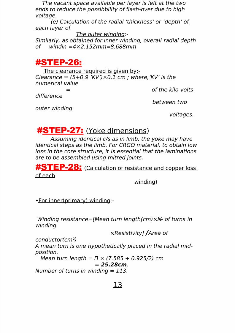
The vacant space available per layer is left at the twoends to reduce the possibbility of flash-over due to highvoltage.
(e) Calculation of the radial ‘thickness’ or ‘depth’ of each layer of
The outer winding:-Similarly, as obtained for inner winding, overall radial depthof windin =4×2.152mm=8.688mm
#STEP-26: The clearance required is given by:-Clearance = (5+0.9 ’KV’)×0.1 cm ; where,’KV’ is thenumerical value
= of the kilo-voltsdifference
between twoouter winding
voltages.
#STEP-27: (Yoke dimensions) Assuming identical c/s as in limb, the yoke may haveidentical steps as the limb. For CRGO material, to obtain lowloss in the core structure, it is essential that the laminationsare to be assembled using mitred joints.
#STEP-28: (Calculation of resistance and copper loss
of eachwinding)
•For inner(primary) winding:-
Winding resistance=[Mean turn length(cm)×№ of turns inwinding
×Resistivity] / Area of conductor(cm²)
A mean turn is one hypothetically placed in the radial mid- position.
Mean turn length = Π × (7.585 + 0.925/2) cm= 25.28cm.
Number of turns in winding = 113.
13
8/3/2019 Transformer Design Report
http://slidepdf.com/reader/full/transformer-design-report 14/14
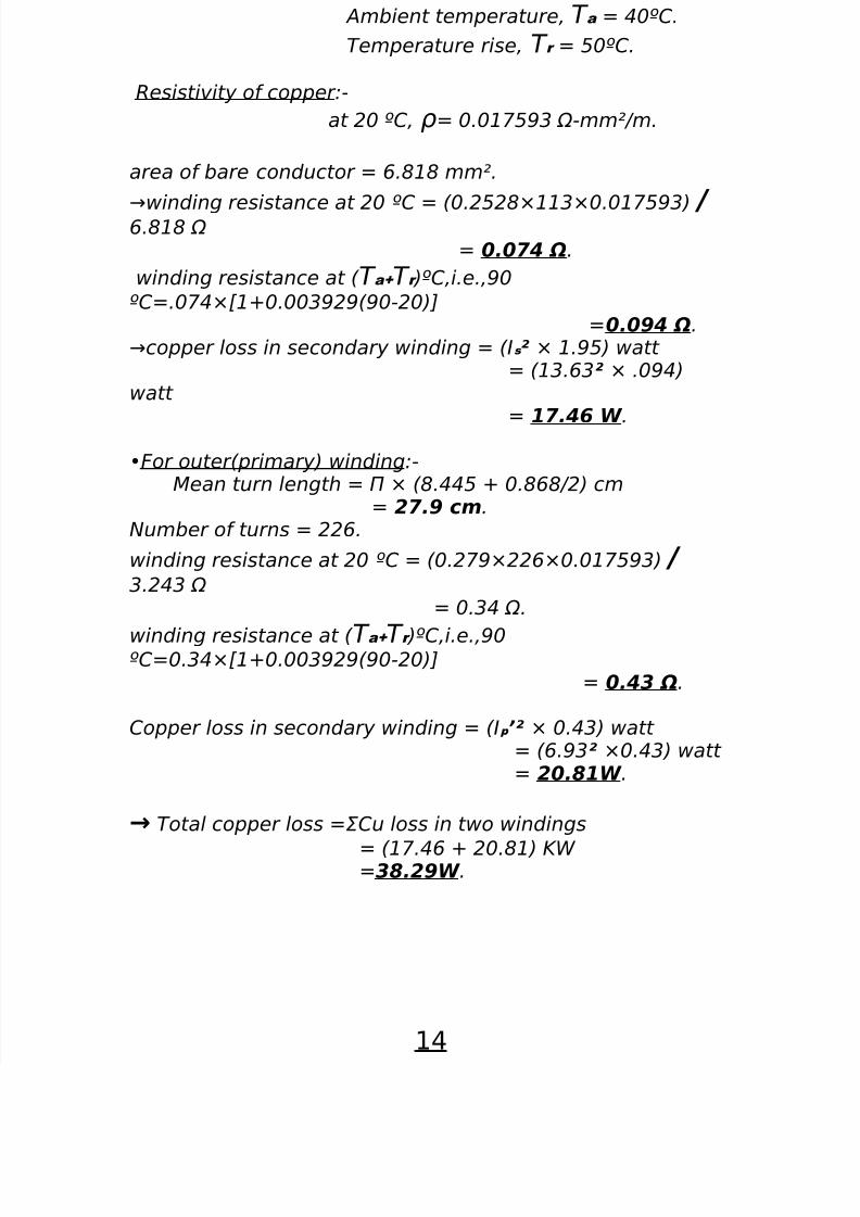
Ambient temperature, T a = 40ºC.
Temperature rise, T r = 50ºC.
Resistivity of copper:-
at 20 ºC, ρ= 0.017593 Ω-mm²/m.
area of bare conductor = 6.818 mm².
→winding resistance at 20 ºC = (0.2528×113×0.017593) / 6.818 Ω= 0.074 Ω.
winding resistance at ( T a+ T r )ºC,i.e.,90
ºC=.074×[1+0.003929(90-20)]=0.094 Ω.
→copper loss in secondary winding = (Is ² × 1.95) watt = (13.63² × .094)
watt
= 17.46 W .
•For outer(primary) winding:-Mean turn length = Π × (8.445 + 0.868/2) cm
= 27.9 cm.Number of turns = 226.
winding resistance at 20 ºC = (0.279×226×0.017593) / 3.243 Ω
= 0.34 Ω.
winding resistance at ( T a+ T r )ºC,i.e.,90ºC=0.34×[1+0.003929(90-20)]
= 0.43 Ω.
Copper loss in secondary winding = (Ip ’² × 0.43) watt = (6.93² ×0.43) watt = 20.81W .
→ Total copper loss =ΣCu loss in two windings
= (17.46 + 20.81) KW =38.29W .
14