pump station overview
TRANSCRIPT

1
Pump Station Overview

2
Today’s Objectives
� Pump Basics
� Review pump varieties
� Review pump applications
� Understand what’s needed to get a pump quoted
� Review competitive stations

3
Pump Station Basics
� Pressure versus Head
� Pressure can be measured in pounds per square inch (psi) or in the height of a column of water (feet)
� One foot of water = .433 pounds per square inch
� One pound per square inch = 2.31 feet of water

4
Pump Station Basics
� Pumps create pressure not flow– XX gpm in – XX gpm out at an increased pressure of psi
– The available flow is a function of the water source not a function of the size of the pump
� Pumps create specific pressure at rated flow– Constant pressure / flow curve
– As flow increases – pressure decreases
– As flow decreases – pressure increases
� Variable Frequency Drives (VFD’s) are used when flow demand varies at constant pressure – Like an accelerator on a car – varies motor / pump speed
– Not needed when flow is constant
– Can also vary pressure for zone control

5
Pump Station Basics
� Inlet pipe size some indication of flow
� Elevation – impacts how the pumps are rated
� The discharge of a pump is usually stated in Feet
� The discharge of a pump station is usually stated in PSI

6
Pump Station Basics
� Elevation Affects Pump Performance
� Atmospheric Pressure at sea level is 14.7PSI = 33.96FT
� Atmospheric pressure above sea level:� 14.7PSI – (0.0005 x Altitude above sea level) � For Mt Lemmon in Arizona, 14.7PSI – (0.0005 x 9000FT) = 10.2PSI
� Motors are rated at nameplate to 3300FT.
�Motors above 3300FT are de-rated. 4% every 1640FT above 3300FT.

7
What You Need to Know to Quote a Pump
� Water source
� Outlet pressure in psi or head in feet
� Flow in gallons per minute
� Electrical power for the pump
� Elevation

8
What is the Water Source?
� Well
� Lake or Pond
� River or Ditch
� Public Source
� Above Ground Tank
� Below Ground Tank
� Potable Water
� Well Water
� Reclaim Water
� Agriculture Water
� Snowmelt or Storm runoff
� Chiller or A/C Water
� Rainwater

9
Electrical Power
� Most common types of power in U.S.
– 460 V, 60Hz, 3Φ
� Can power pumps up 500HP
– 230 V, 60Hz, 3Φ
� Can power pumps up to 100HP
– 230 V, 60Hz, 1Φ
� The largest motor available in 1Φ 230V is 10HP
� Rest of the World Power:
– Canada: 575 V, 60Hz, 3Φ
– Asia & Middle East: 380V, 50Hz, 3Φ

10
Boost Application
� Similar to Flooded Suction with positive head or pressure to pump inlet
� Water supplied to inlet of pump in enclosed pipe (e.g. city main) – not open to atmosphere
� Must have minimum inlet head or pressure to operate properly

11
Booster Application
Suction Discharge
20 PSIG 80 PSIG
Pump that is developing 60 PSI (138.6 Feet of Head)

12
Flooded Suction
� Flooded Suction is where water level is located above the inlet to the pump
� Positive head or pressure to pump inlet
� Water source is open to atmosphere
� Must have minimum inlet head or water level to operate properly

13
Flooded Suction Application
Suction Discharge
5 PSIG 55 PSIG
Pump that is developing 50 PSI (115.5 Feet of Head)
Tank

14
Suction Lift
� Suction Lift is where the water level is below the inlet of the pump
� Atmospheric pressure pushes water up pipe to inlet of pump (e.g. straw in water glass)
� Locate the pump as close to the water surface as is practical
� Rule of thumb – maximum height of station above water level is 15 vertical feet

15
Suction Lift Application
8’
Suction piping friction loss = 3’Atmospheric pressure14.2 PSIA (1,000’ elev.)
• Atmospheric pressure = 32.8’ (14.2 X 2.31)• Elevation of source = -8’ (below pump)• Suction plumbing friction loss = 3’
• NPSHA = 32.8’ – 8’ – 3’ = 21.8’

16
Suction Lift Problems
� Loss of Prime
� The pressure in the suction line is less than atmospheric pressure. A leaking foot valve or suction pipe can allow air to leak into the suction line. Air then replaces water at the inlet to the pump. This is referred to as a Loss of Prime.
� Pumps cannot pump air, so the pump just spins, performing zero hydraulic work.
Air

17
Suction Lift Kits
It is recommended that a check valve be installed at the inlet of the suction piping to ensure water in the suction pipe does not flow back out after pumps stop running. This type of check valve is referred to as a foot valve.

18
Vertical Turbine
� Used in applications that have a wet-well
� Utilizes Vertical Turbine Pumps – thus the name
� Capable of providing high flow and high pressure
� Easy to service the motor
� Requires crane to service the pump

19
Wet Well– Vertical Turbine Application
�

20
Submersible Turbine
� Used in applications for river, pond or underground tanks
� The pump and motor are submersed into the water, thus the name (vertically or horizontally)
� Quiet operation, reduced pump house ventilation requirements
� Lower pump profile versus suction lift
� May plug in dirty water applications
� Less efficient than vertical turbine pumps
� Requires a crane to service motors

21
Submersible – Horizontal Sled

22
What Type of Pump for the Source?
� Well
� Lake or Pond
� River or Ditch
� Public Source
� Above Ground Tank
� Below Ground Tank
� Vertical Turbine or Submersible
� Vertical Turbine or Suction Lift
� Suction Lift or Submersible
� Boost
� Flooded Suction or Boost
� Suction Lift or Submersible

23
Pump Types – Horizontal End Suction & Vertical Multi-Stage
� Centrifugal� Typically up to 2000GPM per pump but can go higher
� Typically up to 130PSI
� Vertical Multi-stage� Up to 500GPM per pump
� Wide range of pressure
Vertical Multi-Stage
HorizontalEnd Suction

24
Vertical Turbine
Submersible Turbine
Pump Types – Vertical Turbine & Submersible
Pump Motor Location
Pump Motor Location
�Vertical Turbine �Typically up to 1000GPM per pump but can go higher�Wide range of pressure
�Submersible �Typically up to 600GPM per pump but can go higher�Wide range of pressure
25
Identifying Pump Components

26
D Series Control Cabinet

27
D Series Rear View

28
DPX Front View

29
DPX Rear View

30
DPX Control Cabinet

31
Requesting A Quotation

32
Requesting a Quotation
� Fill out Job Information Form (JIF) available on Rain Bird Website
� Complete as much contact information as possible
� New Specifier Identification
� Specify whether indoors or outdoors
� Specify available power

33
Requesting a Quotation
� Identify type of Application – boost, flooded suction, suction lift, wet well, or submersible
� State flow and boost requirements
� Identify options

34
Rain Bird Pump Product Overview

35
2009 Pump Stations – Product Line
Large Commercial Intermediate Flow
D SeriesLow Profile

36
Pump Stations – Product Line
Large developments, Waterfalls, Water
features
Application Dependant
Up to 100 and greater
0-10,000Large Commercial
Resorts, Large Parks, Nurseries, Zoos, Botanic Gardens, Racetracks,
Stadiums
$15K-$35KUp to 600-750Intermediate Flow
Schools, Parks, Sports Field, Roads, Medians
$10K-$25KUp to 300-300D Series
Large residential turf, drip, boost applications
$9K – $15KUp to 100-150Low Profile (LP)
ApplicationsPrice RangePumps (HP)
Flow
(GPM)

37
Low Profile (LP)
� Aluminum Enclosure – 52”L x 36”W x 35”H
� Powder Coated Skid & Piping
� Plumbing thru wall or slab
� VFD Driven Vertical Multistage or Horizontal End Suction
� Nema 3R Enclosure w/ Touchscreen Operator Display
� Relay Start or Optional Pressure Start
� Thermal & low pressure flow protection
� Circuit Breaker protection

38
Low Profile – Vertical Multistage

39
Low Profile - Horizontal End Suction
40
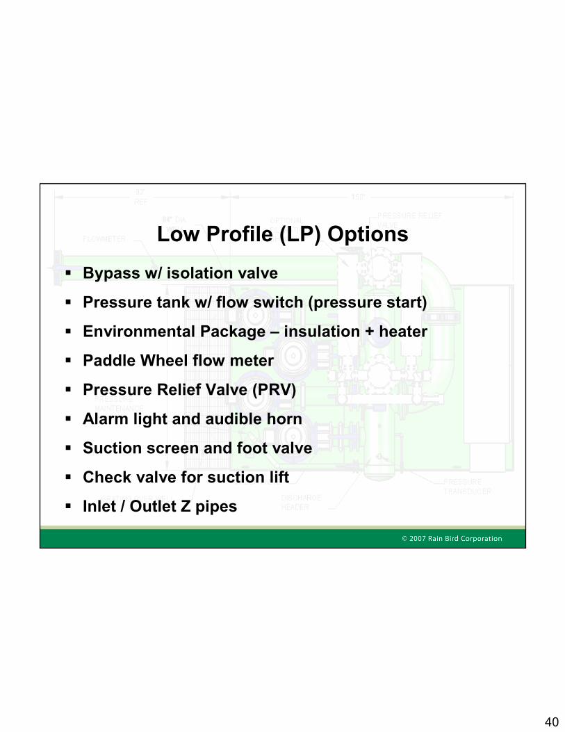
Low Profile (LP) Options
� Bypass w/ isolation valve
� Pressure tank w/ flow switch (pressure start)
� Environmental Package – insulation + heater
� Paddle Wheel flow meter
� Pressure Relief Valve (PRV)
� Alarm light and audible horn
� Suction screen and foot valve
� Check valve for suction lift
� Inlet / Outlet Z pipes

41
D Series
� Powder Coated Enclosure (PCE)– 72”L x 36”W x 52”H
� PCE available in Green or Tan
� Powder Coated Piping and Enclosure
� Plumbing thru wall or slab
� Front & Rear Doors for Easy Access
� Forced Air Ventilation w/ optional heater
� D, DP, DPX Versions

42
Sized for the Application� D
– Basic suction or boosting application up to 300 GPM / 150 PSIG– Limited features or controls– Single pump application only
� DP– Requires more controls such as lake level, remote monitoring, or flow adjustments
– Required if application needs a “Self-Cleaning” suction screen– Multi-pump applications
� DPX– High temperature climates requiring a fully enclosed, liquid cooled electrical panel (heat exchanger).
– Pump station monitoring and control from the site control computer desired (full optional touch screen required)

43
Control Panel
� Nema 4 Controls Enclosure w/ optional water cooled heat exchanger
� Variable Frequency Drive (VFD) on all models for maximum energy efficiency
� Optional Programmable Logic Controller allows advanced functionality beyond pressure and flow control

44
Control Panel
� Emergency Shutdown w/ manual bypass
� Circuit Breakers instead of fuses
� Auto Restart on power loss ensures seamless operation
� Thermal protection – motor shutdown
� Low pressure discharge - run dry protection
� Full Alarms and safety features to protect equipment and irrigation piping

45
User Display
GT1020 Monochrome Touch Screen (standard)
E1071 Full Color Touch Screen (optional)
Optional remote monitoring software

46
D Series Options
� Enclosure – Green or Tan or Marine
� Exhaust Fan for Enclosure
� Enclosure Heater
� Paddle Wheel flowmeter or upgrade to Magmeter
� Lake Level Control
� Pump Bypass piping
� Pressure Relief Valve (PRV)
� Power Zone Transformer for 115 or 230 VAC auxiliary power

47
D Series Options
� Cable or Radio Modems for remote communications
� Filtration (Rain Bird, Amiad, VAF, Tekleen, Orival, wye strainer or other)
� Self Cleaning or Stainless Steel box intake screen
� Discharge Z-Pipe w/ FNPT ports
� Foot Check Valve for Suction Lift Applications
� Power Conditioner for poor quality power

48
Testing Facility – State-of-the-Art
� Every station is fully water tested before shipment
� System check is the same completed at start-up in the field
� Hydraulics, electronics, & software is verified under full speed operation
Full Flow Hydraulic and Electrical Testing

49
Intermediate Station

50
Intermediate Flow Pump Station

51
Intermediate Enclosures
� Marine Enclosure– Custom sized for skid
– Front and rear access doors
– Can be unbolted and lifted off
� Wooden Building– Sizes range from 6’x 6’ to 16’x 24’
– Doors sizes range from 3’ to 8’ wide
– Multiple color choices
– 10 year warranty
� Powder coated piping for durability
� Plumbing connection thru wall or slab
� Forced Air Ventilation w/ optional heater

52
Submersibles

53
Floating Submersibles

54
Engineered Stations

55

56
Unique Features / Differentiators

57
Pump Station Leadership
� Superior Electronics Design
– Circuit Breakers instead of old fashioned fuses
– Labeled wires, clean wire runs and documentation
� Variable Frequency Drives (VFD)
– Greater efficiency and unmatched energy savings
– VFD per motor
� Powder Coating Technology & Protection
– Polyester Powder Coated components both inside and outside for extra protection

58
Pump Station Leadership
� Pump Controller and Software
– An intuitive multi-lingual Color Touch Screen operator interface instead of a text display
– Available remote monitoring software
� Fully Engineered System
– CAD and 3-D Drawings
� Full Factory Testing prior to shipment
– Actual full speed water testing
� Phone Support & Problem Escalation thru GSP

59
Superior Electronics Design

60
Superior Electronic Design
� An Industrial Circuit Breaker is good for thousands of trips and has three visible positions:
� 1) Open, 2) Shut, or 3) Tripped
� A fuse is good for one over current transient, and offers zero visible indication of its status.

61
Circuit Breakersinstead of Fuses (a station can be down because of a single fuse)
Superior Electronics Design

62
Variable Frequency Drive (VFD)
Every main motor on a Rain Bird Pump Station is started on the VFD
VFD saves energy by only powering the pumps that are needed based upon demand
VFD starting of every motor provides motor longevity
Helps minimize pressure surge on irrigation piping

63
Solid Pump Station Control Panels
Eliminate moving parts –contactors, surge protection, relays
Provides best motor life w/ power conditioning & motorProtection
Quick repair time: less wiring and VFD error codes reveal problems quickly.
Each motor is controlled by its own VFD

64
Powder Coating Technology & Protection
Polyester Powder Coating
– Applied Top, Bottom, Inside and Out.
– 2 -3 times as thick as typical industrial paint coatings
– Polyester powder does not easily flake or chip
– Testing proves it’s the best coating in the industry
– Internal powder coating

65
Powder Coating Technology
Rain Bird’s powder coat paint scored a 10 on an ASTM corrosion test. The competition’s paint
scored a 4 on the very same test.
Rain Bird Test Sample following 1,400 hours of salt-spray.

66
Powder Coated Flat Steel Deck VsLiquid Coated Diamond Deck
Both stations are located near the east coast and are of the same vintage (~8 years).

67
Fully Engineered Pump Station
� All pump stations are custom engineered using our 3-D CAD design system
� 3-D CAD saves time and money – no preassembly
� Shop drawings can be generated within 2 hours of design completion
� .DWG and .PDF typical drawings available with quotation
� E drawing is available for customer presentation
� Customization can save money in renovation of existing stations
� New Specifier CD and Thumb drives

68
And enclosed horizontal end-suction systems as well

69
Fully Engineered System

70
Fully Engineered System

71
Fully Engineered System

72
Custom engineering allowed Arthur Pack Golf Course to use its existing well cap, saving the golf
course $10k in construction costs.
One Size Does Not Fit AllCustom Application

73
Display Options
GT1020 Monochrome Touch Screen (Standard)
E1071 Full Color Touch Screen (Optional)

74
Color Touch Screen – Enhanced Colors
• Increased clarity
• Increased readability in brighter lights
Pumps Off = Grey Pumps Enabled (Ready to Run) = YellowPump On VFD = BluePumps On (Running at 100%) = Green

75
Lake Level Settings
NEW – Requires Analog Sensor Original - Digital
76
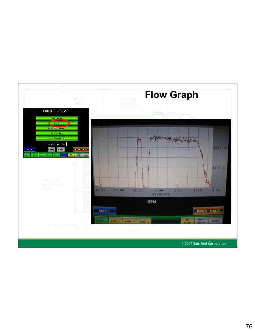
Flow Graph

77
Site Control/Smart Pump
Pump Manager™ provides remote computer access for monitoring and control of the pump station.
• Smart Pump™provides direct and real time communication between the pump station and the central control system (Site Control)
• Adjusts flow demand based on actual field conditions to maximize pump efficiency

78
Smart Pump™ Video
Key Advantages1. Operate at Full Capacity – reduce the water window2. Identifies Pipe Breaks – avoid major washout damage3. Identifies a Pump Loss – Continue irrigation4. Customer Notification – Stay connected
www.Rainbird.com

79
Set / Start
Rain Bird Services Corporation

80
Start-up Facts
� Start-up is the first service event
� Most service issues can be traced back to start-up
� There are generally three tiers of customers involved in every start-up
� A successful start-up is crucial for future sales
� RBSC manages all start-ups

81
Pump Station Start-up Process
� The start-up process begins when the pump station is in early production
� RBSC monitors the pump station during production and keeps the customer informed
� RBSC acts as liaison between the Plant and the Customer
� RBSC manages the delivery communication of all domestic pump stations
� RBSC manages communication until a pump station is ready for start-up
� RBSC coordinates the start-up service event
� RBSC follows up within 24 hours of a successful start-up to ensure the customer’s complete satisfaction
� RBSC follows up within 30-60 days to ensure customers’ continued satisfaction (Customer Acceptance)

82
Total “Customer” Satisfaction Model
� RBSC has identified (in general) three tiers of customers� Distributors� Contractors� End-Users
� RBSC engages all three tiers of customers during the start-up process� Distributors: Engaged during production through delivery (and in some cases
through start-up)� Contractors: Engaged during production through 24-hour start-up completion
follow-up� End-users: Engaged at Customer Acceptance (30-60 post start-up)

83

84
Contacts
Sr. Product Manager – Gordon Van Dyke
1-520-468-9743 or [email protected]
Quotes – [email protected]
Questions locally – Check with your Rain Bird Sales Manager