pvmet-150 instructions rev. 3 - rainwise
TRANSCRIPT

PVMET-150
User’s Guide
Date: 4/14/14 Revision: 3

- 2 -
Copyright© 2014 by RainWise, Inc.
All rights reserved. No part of this work may be reproduced in any form except by
written permission of the publisher. All rights of translation are reserved.
PVMET™ is a trademark of RainWise, Inc.

- 3 -
INTRODUCTION............................................................................................................. 5
UNPACKING THE SYSTEM ................................................................................................. 5
INSTALLING THE WEATHER STATION ................................................................. 5
SITE REQUIREMENTS AND CONSIDERATIONS ................................................................... 5
INSTALLATION ................................................................................................................. 6
Weather Station ........................................................................................................... 6
Integrated Irradiance Sensor ...................................................................................... 6
PV Temperature Sensors............................................................................................. 6
WIRING ............................................................................................................................ 7
Connecting External PV Cell Temperature Sensors ................................................... 8
Connecting External and Integrated Pyranometer Sensors ....................................... 8
Connecting RS-485 ..................................................................................................... 9
Connecting the Power Supply ..................................................................................... 9
SUNSPEC AND MODBUS ............................................................................................ 10
SERIAL/ GENERAL .......................................................................................................... 10
REGISTER MAP: ............................................................................................................. 10
Registers start at holding register 40,001................................................................. 10
Changing the Modbus Device Address ..................................................................... 11
Setting the Pyranometer Calibration Constant......................................................... 12
COMMAND MODE:...................................................................................................... 13
COMMAND SET .............................................................................................................. 13
Get Column Headers: HEADER ............................................................................... 13
Get Current Data: NOW ........................................................................................... 13
Auto Output: AUTO .................................................................................................. 14
Software Reboot: REBOOT ...................................................................................... 14
Version Information: VERSION ............................................................................... 14
Modbus Device Address: MBID ............................................................................... 15
Serial Number: SERIAL ............................................................................................ 15
Command Mode: EXIT ............................................................................................. 15
Calculating the Checksum: ....................................................................................... 16
SOFTWARE/FIRMWARE UPDATES ........................................................................ 18
MINIMUM SYSTEM REQUIREMENTS ................................................................... 18
RS-485/422 ................................................................................................................ 18
Software .................................................................................................................... 18
MATERIAL SPECIFICATIONS ................................................................................. 19
Enclosure: ................................................................................................................. 19
Pyranometer Sensor: ................................................................................................ 19
Ambient Air Temperature Sensor: ............................................................................ 19
PV Panel Temperature Sensors: ............................................................................... 19
Electronics: ............................................................................................................... 19
Physical: ................................................................................................................... 19

- 4 -
HARDWARE SPECIFICATIONS ............................................................................... 20
COMMON SPECIFICATIONS ............................................................................................. 20
PYRANOMETER SENSORS ............................................................................................... 20
AMBIENT AIR TEMPERATURE SENSOR: .......................................................................... 20
PV PANEL TEMPERATURE SENSORS: ............................................................................. 20
RS-485/422 SERIAL SPECIFICATIONS ............................................................................ 20
CONTACT INFORMATION ........................................................................................ 21
WARRANTY................................................................................................................... 21

- 5 -
Introduction The PVMET - 150 weather station is a compact and economical solution for photovoltaic
installations. It is capable of measuring ambient air temperature, two PV panel
temperatures, and two pyranometers. The station was specifically designed to measure
second-class, first-class, or secondary-standard pyranometers in a global and plane-of-
array configuration. The PVMET – 150 is Sunspec compliant and uses a 2-wire half
duplex serial port for Modbus communication to a host.
Unpacking the System
When unpacking the system the following components should be located.
A1200 – PVMET -150 Sensor Assembly
A2101 – PV Cell Temperature Sensor
A1030 – Sensor Assembly Mounting Mast
PVMET -150 User’s Guide
If the system was ordered with any
accessory, it should be located while
unpacking the system. The available
accessories for the PVMET -150 are listed
below.
A2101 – PV Cell Temperature Sensor
A202X – Pyranometer Sensor, The
number “X” is dependent on model of
pyranometer.
A203X - Integrated Pyranometer Mount,
The number “X” is dependent on model of
pyranometer.
A3000 - Mono-Mount
A3010 – Tripod Galvanized Steel
A3020 - Flat Roof Mount
If any of the components are missing, RainWise Inc. should be contacted.
Installing the Weather Station It is suggested that you operate your system at ground level and make sure that all
components operate properly prior to installation.
If any of the components are damaged or malfunctioning upon receipt, RainWise should
be contacted.
Site Requirements and Considerations
Ambient air temperature and irradiance can be affected by obstructions and local
topography. Each site is different and presents challenges in its own unique way. Any
object, in excess of 10 degrees above the plane of the irradiance sensor, must not block
the sensor. The PVMET -150 sensor assembly, which contains the ambient air

- 6 -
temperature, should be no closer than 4 times any obstruction’s height and should be
placed away from any dark, heat-absorbing surfaces.
When roof-mounting the sensor assembly, the unit should be mounted toward an edge of
the roof preferably on the prevailing wind side of the building and should be at least 2 1/2
feet above the roofline. Avoid locating the station near any heat sources such as chimneys
or vents.
Installation
Weather Station
Mount the support mast securely. This may be done by using the Mono-Mount, Tripod,
or Flat-Roof-Mount, which are sold as an accessory to the PVMET - 150. The mast may
also be attached to a support structure using U-Bolts. Do not tighten the support structure
to the PVMET -150 unit; it will need to be first oriented to the correct direction.
Rotate the assembled unit until the electronics enclosure faces TRUE SOUTH or TRUE
NORTH if you are in the northern or southern hemisphere, respectively. Secure the
support mast to the assembly. Rotation is prevented by lining up the two holes in each
mast.
Integrated Irradiance Sensor
When the PVMET -150 is ordered with a pyranometer and
integrated pyranometer mount it will pre-installed on the
unit. The pyranometer mount allows for the measurement
of global or plane of array irradiance. To accurately
measure this quantity, the sensor must be adjusted to the
appropriate angle. This is done by using a 5/32” or 4mm
Allen wrench to loosen the adjustable mounting bracket
to the same angle as the solar panel array. For global
irradiance measurements, the sensor should be fixed in a
horizontal position.
PV Temperature Sensors
This sensor is designed to attach directly to any solar
panel. When placed on the center of the back of the
panel, it accurately measures the temperature of the
panel.
Prior to installation of the PV temperature sensor onto the
PV panel, the installation area of the panel back should
be thoroughly cleaned. This cleaning will ensure a good
bond between sensor and panel and allow for accurate
panel temperature readings.
After cleaning, peel off the protective adhesive tape on the temperature sensor and stick it
onto the panel. Firmly press the sensor into place. Refer to the picture on the next page.

- 7 -
The cable should be secured within 8 inches of the
temperature-sensing element.
Run the cable back to the PVMET -150 unit and connect
to the PV temperature sensor terminals.
If the cable length of 25ft is insufficient for the
installation, additional cable can be added to the existing
cable. If this is done, an accuracy-derating factor must be
added to the overall temperature accuracy of this sensor.
For every 100ft of cable added, a derating factor of -
0.125°C must be taken into account.
Wiring
To enter the enclosure with a cable, the lid must first be removed. Remove the four
Philips head screws from the back of the enclosure. Once the lid is removed, the circuit
board is exposed. The inside of the enclosure will appear as below.
When replacing the cover, make sure that all installed cables are pinched by the black
foam on the bottom of the enclosure. This will enable a weather tight seal.

- 8 -
Connecting External PV Cell Temperature Sensors
The PV cell temperature sensors are not polarity sensitive. Therefore, each signal wire is
interchangeable. The sensor comes with a 25ft length of cable. An additional PV cell
temperature sensor is sold as an accessory and can be installed into the unit if needed.
PV Cell Temperature Terminals
PV Temp #1: Signal
PV Temp #1: Signal
PV Temp #1 Shield: Cable Shield and Drain
Additional PV Cell Temperature Terminals
PV Temp #2: Signal
PV Temp #2: Signal
PV Temp #2 Shield: Cable Shield and Drain
Connecting External and Integrated Pyranometer Sensors
When the PVMET-150 is ordered with an integrated pyranometer it will come pre-
installed in the Pyranometer #1 connector.
An additional pyranometer can be integrated into the unit. This is an accessory to the
PVMET-150. The use of two pyranometers creates a complete solution for solar monitor.
This configuration enables the capture of both global and plane of array irradiance.
Integrated Pyranometer Terminals
Pyranometer #1: Signal Positive
GND: Signal Negative
Shield: Cable Shield and Drain
Additional Pyranometer Terminals
Pyranometer #2: Signal Positive
GND: Signal Negative
Shield: Cable Shield and Drain
If a pyranometer is used that is not factory installed, a sensor specific sensitivity constant
must be saved to the PVMET-150. This sensitivity constant is issued by the manufacture
of the pyranometer and are typical in units of µV/W/m². For more information see
“Setting the Sensitivity Constant for Pyranometers”.
- 9 -
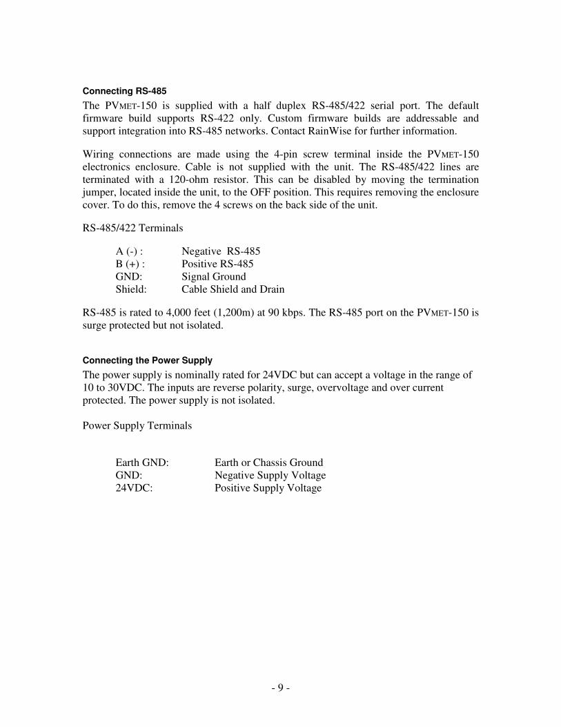
Connecting RS-485
The PVMET-150 is supplied with a half duplex RS-485/422 serial port. The default
firmware build supports RS-422 only. Custom firmware builds are addressable and
support integration into RS-485 networks. Contact RainWise for further information.
Wiring connections are made using the 4-pin screw terminal inside the PVMET-150
electronics enclosure. Cable is not supplied with the unit. The RS-485/422 lines are
terminated with a 120-ohm resistor. This can be disabled by moving the termination
jumper, located inside the unit, to the OFF position. This requires removing the enclosure
cover. To do this, remove the 4 screws on the back side of the unit.
RS-485/422 Terminals
A (-) : Negative RS-485
B (+) : Positive RS-485
GND: Signal Ground
Shield: Cable Shield and Drain
RS-485 is rated to 4,000 feet (1,200m) at 90 kbps. The RS-485 port on the PVMET-150 is
surge protected but not isolated.
Connecting the Power Supply
The power supply is nominally rated for 24VDC but can accept a voltage in the range of
10 to 30VDC. The inputs are reverse polarity, surge, overvoltage and over current
protected. The power supply is not isolated.
Power Supply Terminals
Earth GND: Earth or Chassis Ground
GND: Negative Supply Voltage
24VDC: Positive Supply Voltage
- 10 -
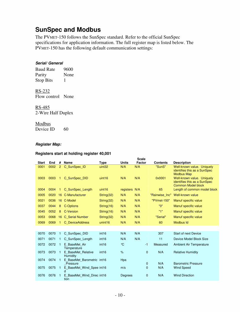
SunSpec and Modbus The PVMET-150 follows the SunSpec standard. Refer to the official SunSpec
specifications for application information. The full register map is listed below. The
PVMET-150 has the following default communication settings:
Serial/ General
Baud Rate 9600
Parity None
Stop Bits 1
RS-232
Flow control None
RS-485
2-Wire Half Duplex
Modbus
Device ID 60
Register Map:
Registers start at holding register 40,001
Start End # Name Type Units Scale Factor Contents Description
0001 0002 2 C_SunSpec_ID uint32 N/A N/A "SunS" Well-known value. Uniquely identifies this as a SunSpec Modbus Map
0003 0003 1 C_SunSpec_DID uint16 N/A N/A 0x0001 Well-known value. Uniquely identifies this as a SunSpec Common Model block
0004 0004 1 C_SunSpec_Length uint16 registers N/A 65 Length of common model block
0005 0020 16 C-Manufacturer String(32) N/A N/A "Rainwise_Inc" Well-known value
0021 0036 16 C-Model String(32) N/A N/A "PVmet-150" Manuf specific value
0037 0044 8 C-Options String(16) N/A N/A "0" Manuf specific value
0045 0052 8 C-Version String(16) N/A N/A "1" Manuf specific value
0053 0068 16 C_Serial Number String(32) N/A N/A "Serial" Manuf specific value
0069 0069 1 C_DeviceAddress unint16 N/A N/A 60 Modbus Id
0070 0070 1 C_SunSpec_DID int16 N/A N/A 307 Start of next Device
0071 0071 1 C_SunSpec_Length int16 N/A N/A 11 Device Model Block Size
0072 0072 1 E_BaseMet_Air Temperature
int16 °C -1 Measured Ambient Air Temperature
0073 0073 1 E_BaseMet_Relative Humidity
int16 % 0 N/A Relative Humidity
0074 0074 1 E_BaseMet_Barometric_Pressure
int16 Hpa 0 N/A Barometric Pressure
0075 0075 1 E_BaseMet_Wind_Speed
int16 m/s 0 N/A Wind Speed
0076 0076 1 E_BaseMet_Wind_Direction
int16 Degrees 0 N/A Wind Direction
- 11 -
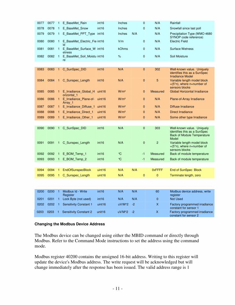
0077 0077 1 E_BaseMet_Rain int16 Inches 0 N/A Rainfall
0078 0078 1 E_BaseMet_Snow int16 Inches 0 N/A Snowfall since last poll
0079 0079 1 E_BaseMet_PPT_Type int16 Inches N/A N/A Precipitation Type (WMO 4680 SYNOP code reference)
0080 0080 1 E_BaseMet_Electric_Field
int16 V/m 0 N/A Electric Field
0081 0081 1 E_BaseMet_Surface_Wetness
int16 kOhms 0 N/A Surface Wetness
0082 0082 1 E_BaseMet_Soil_Moisture
int16 % 0 N/A Soil Moisture
0083 0083 1 C_SunSpec_DID int16 N/A 0 302 Well-known value. Uniquely identifies this as a SunSpec Irradiance Model
0084 0084 1 C_Sunspec_Length int16 N/A 0 5 Variable length model block =(5*n), where n=number of sensors blocks
0085 0085 1 E_Irradiance_Global_Horizontal_1
uint16 W/m² 0 Measured Global Horizontal Irradiance
0086 0086 1 E_Irradiance_Plane-of-Array_1
uint16 W/m² 0 N/A Plane-of-Array Irradiance
0087 0087 1 E_Irradiance_Diffuse_1 uint16 W/m² 0 N/A Diffuse Irradiance
0088 0088 1 E_Irradiance_Direct_1 uint16 W/m² 0 N/A Direct Irradiance
0089 0089 1 E_Irradiance_Other_1 uint16 W/m² 0 N/A Some other type Irradiance
0090 0090 1 C_SunSpec_DID int16 N/A 0 303 Well-known value. Uniquely identifies this as a SunSpec Back of Module Temperature Model
0091 0091 1 C_Sunspec_Length int16 N/A 0 2 Variable length model block =(5*n), where n=number of sensors blocks
0092 0092 1 E_BOM_Temp_1 int16 °C -1 Measured Back of module temperature
0093 0093 1 E_BOM_Temp_2 int16 °C -1 Measured Back of module temperature
0094 0094 1 EndOfSunspecBlock uint16 N/A N/A 0xFFFF End of SunSpec Block
0095 0095 1 C_Sunspec_Length uint16 N/A 0 0 Terminate length, zero
0200 0200 1 Modbus Id - Write Register
int16 N/A N/A 60 Modbus device address, write register
0201 0201 1 Lock Byte (not used) int16 N/A N/A 0 Not Used
0202 0202 1 Sensitivity Constant 1 uint16 uV/M^2 -2 X Factory programmed irradiance constant for sensor 1
0203 0203 1 Sensitivity Constant 2 unit16 uV/M^2 -2 X Factory programmed irradiance constant for sensor 2
Changing the Modbus Device Address
The Modbus device can be changed using either the MBID command or directly through
Modbus. Refer to the Command Mode instructions to set the address using the command
mode.
Modbus register 40200 contains the unsigned 16-bit address. Writing to this register will
update the device's Modbus address. The write request will be acknowledged but will
change immediately after the response has been issued. The valid address range is 1

- 12 -
through 255. Write requests outside this range will not update the address. The address is
stored in flash memory and will remain in affect permanently or until it is changed again.
In order to use the Modbus method to change a device address you must know the current
device address. If you do not know the address and cannot scan for it, you will have to
use the Command Mode. The command mode requires a PC and does not require an
address. It can only be used with a point-to-point RS-485 connection.
Setting the Pyranometer Calibration Constant
Each pyranometer has a specific sensitivity calibration constant that is provided by the
sensor’s manufacturer. The PVmet-150 must be set to match this value. If your station
was purchased with an integrated sensor, the appropriate calibration constants have been
preprogrammed at the factory. You may need to adjust these constants if you replace or
recalibrate the sensors.
The µV/W/m² constants for each sensor should be written to Modbus holding registers
40202 & 40203 respectively. The sensitivity number provided by the sensor manufacturer
should be between 5.00 and 40.00 µV/W/m². This number should be multiplied by 100
and written to the appropriate register as a 16-bit unsigned integer. A sensitivity of say
12.56 would be written as 1256. Once written, the setting will be saved to flash memory
and will remain in affect until overwritten. The value will not be lost if power is removed
from the station.

- 13 -
Command Mode:
By default, the PVMET -150 will boot in Modbus mode and will not respond to the
commands listed here. To enter the command mode issue three '+' characters one second
apart. The PVMET -150 will return a message indicating that it is in command mode.
After one minute of inactivity it will exit command mode and return to the default
Modbus mode.
Commands must be terminated with a <CR> character. Responses begin and end with a
<CR><LF>.
If the command syntax or parameters are incorrect the device will respond with ERROR.
If the command is accepted, the device will respond with OK. Commands may not be
chained together. Commands are not case sensitive.
Command Set
Get Column Headers: HEADER
Description: Returns a series of comma-delimited text descriptions. These
descriptions are used to identify the type and order of the returned data in both
NOW and DOWNLOAD commands.
Values: None
Syntax: HEADER
Sample Response:
HDR,"AIR TEMP","PV TEMP1","PV TEMP2","SOLAR","CHIP_TEMP",!213 Key:
HDR : Identifier, HDR= Header, MSG= Message, REC= Data Record, MAX= Maximums and MIN= Minimums.
AIR TEMPT : Current ambient air temperature. PV TEMP1 : First current Back-of-Module temperature. PV TEMP2 : Second current Back-of-Module temperature. SOLAR : Current global horizontal irradiance. CHIP_TEMP : CPU temperature. !XXXX : CRC-16 Checksum. See Calculating the Checksum. NOTE: The parameter count may increase in future models.
Get Current Data: NOW

- 14 -
Description: Returns the current values in a comma-delimited format. The order
of the data values correspond to the output of the HEADER command. NO DATA
is returned if the unit has not received a transmission from the weather station.
Values: None
Syntax: NOW
Sample Response:
22.5,-40.0,-40.0,0, 29.3,!168
Auto Output: AUTO
Description: Automatically outputs current data every second. This is
equivalent to issuing the NOW command every second. This mode will exit upon
reception of any character. If no data is received from the weather station, the units
will not output.
Values: None
Syntax: AUTO
Sample Response:
OK
Software Reboot: REBOOT
Description: Forces a soft reboot of the interface. On boot up the version
information is output.
Values: None
Syntax: REBOOT
Sample Response:
None
Version Information: VERSION
Description: Returns firmware version information.
Values: None
Syntax: VERSION
Sample Response:

- 15 -
Rainwise Inc PVMET-150 Version: 1.0 Build 001 Jun 17
Modbus Device Address: MBID
Description: The Modbus device address can be viewed or changed using this
command. The default is address is 60
Values: ?,1 - 255
Syntax (Read): MBID=?
Syntax (Write): MBID=60
Sample Read Response:
60
Sample Write Response:
OK
Serial Number: SERIAL
Description: The serial number of the device can be viewed or changed using
this command. The serial number string is returned in SunSpec Common block.
Values: ?, character string (31 character limit)
Syntax (Read): SERIAL=?
Syntax (Write): SERIAL=ABC123
Sample Read Response:
ABC123
Sample Write Response:
OK
Command Mode: EXIT
Description: Exits from the command mode. Modbus is not functional in
command mode.
Values: None
Syntax: EXIT
- 16 -
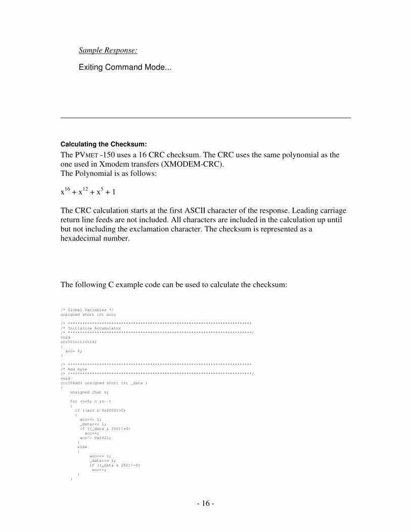
Sample Response:
Exiting Command Mode...
Calculating the Checksum:
The PVMET -150 uses a 16 CRC checksum. The CRC uses the same polynomial as the
one used in Xmodem transfers (XMODEM-CRC).
The Polynomial is as follows:
x16
+ x12
+ x5 + 1
The CRC calculation starts at the first ASCII character of the response. Leading carriage
return line feeds are not included. All characters are included in the calculation up until
but not including the exclamation character. The checksum is represented as a
hexadecimal number.
The following C example code can be used to calculate the checksum:
/* Global Variables */
unsigned short int acc;
/* ****************************************************************************
/* Initialize Accumulator
/* ****************************************************************************/
void
crc16Init(void)
{
acc= 0;
}
/* ****************************************************************************
/* Add byte
/* ****************************************************************************/
void
crc16Add( unsigned short int _data )
{
unsigned char n;
for (n=8; n ;n--)
{
if ((acc & 0x8000)>0)
{
acc<<= 1;
_data<<= 1;
if ((_data & 256)!=0)
acc++;
acc^= 0x1021;
}
else
{
acc<<= 1;
_data<<= 1;
if ((_data & 256)!=0)
acc++;
}
}

- 17 -
}
/* ****************************************************************************
/* Return CRC accumulator
/* ****************************************************************************/
unsigned short int crc16Acc(void)
{
unsigned short int tmp= acc, retval;
crc16Add(0);
crc16Add(0); // add two zeros to get a valid crc
retval= acc;
acc= tmp; //restore acc
return retval;
}

- 18 -
Software/Firmware Updates The software or firmware in the PVMET -150 can be updated or changed using the RS-
485 port. Make sure to read the update instructions carefully and be sure you are
installing the correct software. As with all updates, there are risks associated with
changing the flash memory.
Updates are loaded using a Windows based program called IAPflash. This program is
supplied with the “.enc” file along with instructions. Windows is required to perform
updates. No other operating systems are currently supported.
Minimum System Requirements The PVMET -150 is equipped with an RS-485 serial port.
RS-485/422
Baud rate: 9600 bps
Parity: None
Data bits: 8
Stop bits: 1
Interface mode: 2-wire half duplex
Software
The PVMET -150 is designed to work with an RS-485 Sunspec compliant host. A terminal
emulator program is required to change settings.

- 19 -
Material Specifications Sensor Assembly:
RoHS Compliant
Mast: Anodized Aluminum
Heat Shields: Acrylonitrile Butadiene Styrene
Insolation Senors Bracket: Anodized Aluminum
Hardware: Stainless Steel and Nylon Locknut
Enclosure:
RoHS Compliant
IP65 Rated Outdoor Enclosures
UL 94 V-2
Body: Polycarbonate
Pyranometer Sensor:
RoHS Exempt
Body: Anodized Aluminum
Cable: Santoprene Jacket
Ambient Air Temperature Sensor:
RoHS Compliant
PV Panel Temperature Sensors:
RoHS Compliant
Body: Anodized Aluminum
Adhesive Tape: Acrylic, Titanium Diboride, and Aluminum
Cable: Polyvinyl Chloride Jacket
Electronics:
RoHS Compliant
Physical:
Packaged Weight: 10 lbs.
Packaged Dimensions: 29” x 14” x 8”

- 20 -
Hardware Specifications
Common Specifications
Power Requirements: 10 ~ 30VDC at 50mA
Operational Temperature: -40 ~ 60°C (-40 ~ 140°F)
Humidity: 0-100% Condensing
Pyranometer Sensors
The PVMET -150 is compatible with thermopile-based pyranometers. Please contact
RainWise if you have a specific pyranometer manufacture you would like to use. As an
example of compatible sensors, Kipp & Zonen pyranometers are listed below with their
specifications.
Pyranometer Sensor CMP 3 CMP 6 CMP 11 CMP 21 CMP 22
ISO 9060:1990 Classification Second Class First Class Secondary Standard
Secondary Standard
Secondary Standard
Spectral Range 285 ~ 2800 nm 285 ~ 2800 nm 285 ~ 2800 nm 285 ~ 2800 nm 200 ~ 3600 nm
Maximum Irradiance 2000 W/m2 2000 W/m
2 4000 W/m
2 4000 W/m
2 4000 W/m
2
Response Time to 95% < 18 s < 18 s < 5 s < 5 s < 5 s
Response Time to 63% < 6 s < 6 s < 1.7 s < 1.7 s < 1.7 s
Non-Linearity (0 ~ 1000 W/m2) < 1 % < 1 % < 0.2 % < 0.2 % < 0.2 %
Non-Stability (Change/Yr) < 1 % < 1 % < 0.5 % < 0.5 % < 0.5 %
Directional Error (Up to 80° with 1000 W/m
2 beam)
< 20 W/m2 < 20 W/m
2 < 10 W/m
2 < 10 W/m
2 < 5 W/m
2
Temperature Dependency of Sensitivity
< 5 % (-10 ~ 40°C)
< 4 % (-10 ~ 40°C)
< 1 % (-10 ~ 40°C)
< 1 % (-20 ~ 50 °C)
< 0.5 % (-20 ~ 50 °C)
Tilt Error (at 1000 W/m2) < 1 % < 1 % < 0.2 % < 0.2 % < 0.2 %
Temperature Range -40 ~ 80°C -40 ~ 80°C -40 ~ 80°C -40 ~ 80°C -40 ~ 80°C
Ambient Air Temperature Sensor:
Range: -40 ~ 80°C (-40 ~ 176°F) Accuracy: ± 0.3°C (0.54°F) Thermal Time Constant 30 s
PV Panel Temperature Sensors:
Range: -40 ~ 80°C(-40 ~ 176°F)
Accuracy: ±0.3°C (0.54°F) Thermal Time Constant: 270 s Cable Length 7.62m (25 ft)
RS-485/422 Serial Specifications
Mode: 2-wire half duplex
Connector: 4-position screw terminal, (A,B, signal and earth ground)
Max Speed: 9600 bps
Max. Modbus Poll Rate: 100 ms
Termination: 120 ohms (internal jumper enable)

Contact Information RainWise Inc.
23 Creek CircleBoothwyn, PA19014 USA
Phone: (207)-288-5169
Warranty RainWise, Inc. warrants RainWise, Inc. manufactured PVMET products against defects in
materials and/or workmanship for a period of two years from the date of purchase and
agrees to repair or replace any defective product without charge. Equipment supplied by
RainWise but not manufactured by RainWise is covered by the particular warranty of that
manufacturer.
IMPORTANT: This warranty does not cover damages resulting from accident, misuse or
abuse, lack of reasonable care, the fixing of any attachment not provided with the product
or damage due to a lightning strike. RainWise, Inc. will not reimburse for take-down or
installation charges. RainWise, Inc. will not pay for warranty service performed by a
non-authorized repair service and will not reimburse the consumer for damage resulting
from warranty service performed by a non-authorized repair service. No responsibility is
assumed for any special, incidental or consequential damages.
To return a unit under this warranty, call (800)762-5723 within the continental US or
(207)288-5169. The service department will document the need for repair/replacement and arrange such. Shipping costs from the customer to RainWise are borne by the customer, RainWise will cover return shipment. It is the customer's responsibility to see that the unit is properly packed, preferably in the original box, because damage occurring during return shipment is not covered by this warranty.
NOTE: No other warranty, written or oral, is authorized by RainWise, Inc. This
warranty gives you specific legal rights, and you may also have other rights, which vary
from state to state. Some states do not allow the exclusion of limitation of incidental or
consequential damages, so the above exclusion and limitations may not apply to you.
- 21 -