qmix/qbus mwd communication protocol ˜ a brief …
TRANSCRIPT
ERDOSMILLER
QMIX/QBUS MWD COMMUNICATION PROTOCOL - A BRIEF INTRODUCTION

Copyright © 2017 Erdos Miller 2
Introduction Since inception, one of our passions at Erdos Miller has
been designing and developing measurement while
drilling (MWD) tools. These tools, while only relevant
to a handful of people, are an engineer’s dream given
their complexity and the intense challenge of designing
one that works reliably time and again.
Many years ago, the Tensor corporation brought to
market the first affordable mass market MWD system.
The company took the capabilities that only a few of
the majors, like Schlumberger, Halliburton, and Baker
Hughes possessed and made an affordable system
for the mass market. Thousands were sold, and this
system quickly became the working standard for
smaller service companies, with many compatible third-
party replacement components being developed.
Like most complex systems, there was a need for
machine-to-machine communications. The engineers
at Tensor chose to implement a custom serial protocol
of their own and called it qMIX, also known as qBUS,
q/BUS, q/MIX, or sometimes just q. Given that the
Tensor systems became the working standard, qMIX
also became the standard communication protocol.
Even though these tools were developed many years
ago, they are still prevalent today, and to successfully
develop MWD equipment compatible with a wide array
of today’s tools, one must master qMIX. However,
mastering qMIX and developing compatible software
is a challenge. Little to no documentation exists so
you’re left on your own. You need to break out an
oscilloscope, decode the communication by hand,
and reverse engineer the operation of this complex
communications protocol byte by byte.
Erdos Miller has built dozens of devices that use the
qMIX/qBUS protocol and we can help our clients
achieve the same. This guide is meant to be an
introduction to one of the more obscure protocols we
have ever encountered.
Bus Architecture
The qMIX protocol defines the procedures for
communications over a multipoint link where two
or more processors are connected. The bus is
controlled by a communications bus master (CBM)
which arbitrates all bus traffic. Nodes on the bus have
a unique ID number in the range of 00-99. The bus
master cycles through the address space polling each
node and the addressed node may transmit data at
this time if it is available. Data transfers between nodes
are relayed through the bus master rather than directly
from node to node. The protocol allows for one node
to relinquish bus master status to another node, but in
practice few nodes have the capability of being bus
master; examples include MPUs and some surface
receivers. Data is transferred using predominantly
ASCII characters, although binary data transfers are
also possible.
Typical node addresses in an MWD string are shown in
the table below. Often, MWD tools only contain node
20, the MPU (MPTx20). A table of the qMIX address
space is shown below.
The relationship between the user PC, receiver, and the MPU (other nodes can be connected in parallel with the MPU).
PC Receiver MPURS-232, USB, or Ethernet
qMIX

Copyright © 2017 Erdos Miller 3
Node Address Description
00-04 User PC(s)
05 Surface Receiver (MPRx05)
06 Field Service Primary PC
07 Field Service Secondary PC
08Reserved for Driller’s Remote Terminal (DRT 08)
09 Driller’s Remote Terminal (DRT 09)
20 Downhole Tool (MPTx20)
21-29Reserved for downhole sub-system nodes
30-99 Undefined
The physical layer of the bus consists of a single
communications signal, line 5 on common GE/Tensor
compatible MWD systems. In general, the bus uses
half-duplex asynchronous serial communication at a
5V TTL level. Data characters are transferred at 9,600
baud, 1 start bit, 8 data bits, 1 stop bit, and no parity. In
contrast to common implementations of a 5V UART, the
qMIX bus is inverted and idles at 0V.
Bus Data FlowTwo predominant uses of the qMIX bus are inter-node
communication and configuration of the MWD. The
majority of MWD tools in the field run with a single
node on the bus, the MPU (MPTx20). In these cases,
the qMIX bus simply idles, cycling through polling
sequences of slave IDs (all of which time out).
There are several devices on the market that can
augment a GE/Tensor compatible MWD string by
taking advantage of the qMIX bus, which allows
communication between these devices and the MPU.
Examples of information available through the qMIX
interface include surveys, battery voltage, and flow
state. These devices may also store values to the
MPU, which are transmitted to the surface in survey or
telemetry sequences. Variables available for such use
are called generic variables (GVs).
The settings of an MWD tool can be modified when
the MPU (device address MPTx20) is connected to a
surface receiver (device address MPRx05). The receiver
may negotiate for bus master status, depending on
manufacturer and model.
ASCII control characters shown in bold in the following
examples are non-printable.
Bus Communication Protocol
At power-up, the communications bus master initializes
the qMIX bus and starts polling the slave address
range, inquiring whether the node has any information
to send. The bus master has three primary types of
messages that it sends to the slave devices, including
polling sequences, calling sequences, and message
broadcasts.
Polling Sequence
A polling sequence is sent from the bus master to a
slave device inquiring whether the slave has any data
to send. The slave device will then either send data, if it
has any, or it will indicate that it has no data to transfer.
A typical polling sequence consists of an enquire
prefix (ASCII characters LF CR), a two-digit address
(ASCII encoded), a left arrow (‘<’), and the ASCII enquire
character (ENQ).
An example polling sequence to node address 21 is
shown below. The top line is the human-readable ASCII
form and the lower line shows the corresponding hex
values.
ASCII: LF CR 2 1 < ENQHEX : 0A 0D 32 31 3C 05

The slave device can respond in several ways:
1. With Data — If the slave device has data ready
to transmit to any other node, it starts a transfer
sequence (described in the following sections).
2. No Data — If the slave device has no data to
transfer, it sends an ASCII end-of-transmission (EOT)
character, terminating the calling sequence.
3. Bus Master Request — If the slave device wants
to become the bus master, it can try to negotiate
bus master status with the active bus master. The
bus master can either approve or deny the request.
Most slave devices do not have the capability to
become bus master.
4. Timeout — If there is no slave device to respond to
the calling sequence within a four-character time-
period, the bus master will place an EOT character
on the bus and consider the addressed device
‘offline’.
Calling Sequence
A calling sequence is initiated by the bus master when
it has data ready to be sent to a slave device. The
slave device will acknowledge the calling sequence
if it is ready to receive the data from the bus master. If
the slave device is not ready to receive the data, it will
not acknowledge the calling sequence and the bus
master will repeat the calling sequence later. A typical
calling sequence consists of an enquire prefix (ASCII
characters LF CR), a two-digit address (ASCII encoded),
a right arrow (‘>’), and the ASCII enquire character
(ENQ). An example calling sequence to node address
21 is shown below.
ASCII: LF CR 2 1 > ENQHEX : 0A 0D 32 31 3E 05
The slave device can respond in several ways:
1. Ready to Receive Data — If the slave device is
ready to receive data, it responds to the calling
sequence with an acknowledge (ACK) character.
The bus master will then begin a transmission
sequence to the slave device (described in the
following sections).
2. Currently Not Ready to Receive Data — If the
slave is currently not ready to receive data, it can
place an ASCII NAK character on the bus. This
indicates that the bus master should retry the
calling sequence. The bus master will attempt the
calling sequence periodically until the slave device
responds with an ASCII EOT or ACK character.
3. Cannot Receive Data — If the slave device cannot
receive data it will place an EOT character on the
bus, ending the logical link with the bus master.
In contrast to the ‘Currently Not Ready to Receive
Data’ state, the bus master will not try to resend
the data. This can be used in conditions where the
node is incapable of receiving (or storing) data.
4. Timeout — If the slave device does not respond
within four-character time-periods, the bus
master will retry up to three times. If no response
is received, the bus master will consider the
addressed device ‘offline’.
Message BroadcastMessage broadcasts provide a method of data
transmission to multiple nodes at once. These
messages are generally reserved for non-critical data
as the protocol provides no method to verify that
the messages were received correctly. The structure
of a message broadcast is like a calling sequence,
Copyright © 2017 Erdos Miller 4

Copyright © 2017 Erdos Miller 5
consisting of an enquire prefix (ASCII characters LF
CR), a two-digit address (allowing for wildcards), a right
arrow (‘>’), and the ASCII enquire character (ENQ). It is
then immediately followed by a transmission sequence.
The broadcast sequence is like a regular message
transfer sequence with the exception that the message
transfer sequence (described in the following section)
is terminated by an ASCII EOT character instead of an
ENQ character.
An example broadcast to node addresses 20-29 is
shown below.
ASCII: LF CR 2 # > ENQ HEX : 0A 0D 32 23 3E 05
In this message, the ‘#’ character is a wildcard and
represents all characters 0-9. To broadcast to all nodes
on the bus, the address of ‘##’ would be used.
Recognizing the broadcast, slave devices will receive
the data contained in the message transfer sequence
if the slave’s own address falls into the broadcast
address range. Unlike polling or calling sequences,
slave devices never respond to a message broadcast.
Message Transfer SequenceThe above sections describe three methods that may
result in a data transfer between nodes, including:
1. A polling sequence resulting in a data transfer
from a node to the bus master.
2. A calling sequence resulting in a data transfer
from the bus master to a node.
3. A message broadcast resulting in a data transfer
from the bus master to multiple nodes.
The structure of a message transfer is composed
of three fields that are separated by ASCII control
characters. Italic fields below represent actual data.
ASCII: SOH [header] STX [data] ETX [crc] ENQ HEX : 01 [header] 02 [data] 03 [crc] 05
Header Field
The header field is made up of 14 to 24 characters
and is framed by the start-of-header (SOH) and start-
of-text (STX) ASCII characters. The first 14 characters
define the destination name (D), destination node ID (N),
source name (S), and source node ID (M), using ASCII
characters. This is followed by two characters defining
the message type (T).
ASCII: SOH DDDD NN SSSS MM TT … STX
The first character in the message type field is always
a forward-slash. Possible message types include the
following:
1. /? Designating an inquiry
2. /< Designating a reply (back)
3. /> Designating a download
An additional 10 bytes are reserved for application
dependent information but this is generally not used in
MWD applications.
Data Field
The data field is alpha-numeric ASCII coded data,
either requesting or setting the value of a variable or
field. The data field is framed by the start-of-text (STX)
and end-of-text (ETX) ASCII characters.
CRC Field
The last field of a message transfer sequence is a
4-character hexadecimal block-check field and is
framed by the end-of-text (ETX) and the enquire (ENQ)
Copyright © 2017 Erdos Miller 6
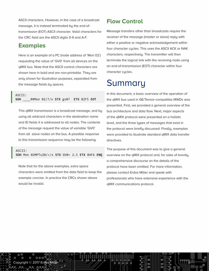
ASCII characters. However, in the case of a broadcast
message, it is instead terminated by the end-of-
transmission (EOT) ASCII character. Valid characters for
the CRC field are the ASCII digits 0-9 and A-F.
Examples
Here is an example of a PC (node address of ‘Mon 02’)
requesting the value of ‘GV0’ from all devices on the
qMIX bus. Note that the ASCII control characters are
shown here in bold and are non-printable. They are
only shown for illustration purposes, separated from
the message fields by spaces.
This qMIX transmission is a broadcast message, and by
using all wildcard characters in the destination name
and ID fields it is addressed to all nodes. The contents
of the message request the value of variable ‘GV0’
from all slave nodes on the bus. A possible response
to this transmission sequence may be the following.
Note that for the above examples, extra space
characters were omitted from the data field to keep the
example concise. In practice the CRCs shown above
would be invalid.
Flow Control
Message transfers other than broadcasts require the
receiver of the message (master or slave) reply with
either a positive or negative acknowledgement within
four character cycles. This uses the ASCII ACK or NAK
characters, respectively. The transmitter will then
terminate the logical link with the receiving node using
an end-of-transmission (EOT) character within four
character cycles.
SummaryIn this document, a basic overview of the operation of
the qMIX bus used in GE/Tensor-compatible MWDs was
presented. First, we provided a general overview of the
bus architecture and data flow. Next, major aspects
of the qMIX protocol were presented on a holistic
level, and the three types of messages that exist in
the protocol were briefly discussed. Finally, examples
were provided to illustrate standard qMIX data transfer
directives.
The purpose of this document was to give a general
overview on the qMIX protocol and, for sake of brevity,
a comprehensive discourse on the details of the
protocol have been omitted. For more information,
please contact Erdos Miller and speak with
professionals who have extensive experience with the
qMIX communications protocol.
ASCII: SOH Mon 02MPTx20/</x STX GV0= 2.5 ETX 84F6 ENQ
ASCII: SOH ____##Mon 02/?/x STX gv0? ETX 82F5 EOT

Copyright © 2017 Erdos Miller 7
About Erdos MillerTurnkey solutions made to last in the harshest environments
With our extensive experience in designing rugged and reliable downhole electronics, software, and surface
equipment, Erdos Miller can solve your oilfield engineering challenges. We have experience designing custom
MWD electronics, firmware, and software for our customer’s downhole and surface equipment needs.
Let us know how we can partner on your next project.
Address
15120 Northwest Fwy.
Ste. 100
Houston, TX 77040
Contact
1-888-337-0869
erdosmiller.com
ERDOSMILLER©Copyright 2017 Erdos Miller. All Rights Reserved.