qos-basics for planners
TRANSCRIPT

8/8/2019 QoS-Basics for Planners
http://slidepdf.com/reader/full/qos-basics-for-planners 1/47
Information and Communication Mobile ____________________________________________________________________________________
Siemens AG NCP-Basics: Guideline Released by: ICM N PG NM NE P3
Information and QoS Basics for Core PlannersJ. Bienert
Communication Version 2.0 Guideline_QoS_Basics_for_Cor
Mobile Networks For internal use only ! Date: 15.04.2003
Author: T. Schnoell
PSE MCS CN32 A30862-X1001-B857-01-7635 Page 1 of 47 page(s)
Basics of Network Configuration
Planning
QoS Basics for Core Planners
Guideline
For internal use only!
Issued by the
Information and Communication Mobile
Networks
Siemensdamm 62
13627 Berlin
© SIEMENS AG 2003
The reproduction, transmission or use of this document or its contents is not permittedwithout express written authority. Offenders will be liable for damages. All rights, includingrights created by patent grant or registration of a utility model or design, are reserved.
Technical modifications are possible. Technical specifications and features are bindingonly in so far as they are specifically and expressly agreed upon in a written contract.

8/8/2019 QoS-Basics for Planners
http://slidepdf.com/reader/full/qos-basics-for-planners 2/47
Information and Communication Mobile ____________________________________________________________________________________
Siemens AG NCP-Basics: Guideline Released by: ICM N PG NM NE P3
Information and QoS Basics for Core PlannersJ. Bienert
Communication Version 2.0 Guideline_QoS_Basics_for_Cor
Mobile Networks For internal use only ! Date: 15.04.2003
Author: T. Schnoell
PSE MCS CN32 A30862-X1001-B857-01-7635 Page 2 of 47 page(s)
In addition to the authors named on the cover page the following persons havecollaborated on this document:
Linduska Kurt PSE MCS CN4Polzer Christian PSE MCS CN4Pregler Peter PSE MCS CN4
For questions please contact one of the responsible pools ([email protected] or [email protected]) within network planning.
The document comprises 47 pages.
The document is based on template Guideline_template.dot.
This issue was last saved on 15.04.2003 07:12.
The document was edited with MS WinWord Version 9.0.
The filename of the main document file was D:\Network_Engineering\CREATED_DOCS\QoSBasics\Guideline_QoS_Basics_for_Core_Planners_V02.doc.

8/8/2019 QoS-Basics for Planners
http://slidepdf.com/reader/full/qos-basics-for-planners 3/47
Information and Communication Mobile ____________________________________________________________________________________
Siemens AG NCP-Basics: Guideline Released by: ICM N PG NM NE P3
Information and QoS Basics for Core PlannersJ. Bienert
Communication Version 2.0 Guideline_QoS_Basics_for_Cor
Mobile Networks For internal use only ! Date: 15.04.2003
Author: T. Schnoell
PSE MCS CN32 A30862-X1001-B857-01-7635 Page 3 of 47 page(s)
Table of Contents:
0 General Information 6 0.1 History..................................................................................................................6 0.2 References...........................................................................................................6 0.3 Abbreviations ......................................................................................................8 0.4 Glossary...............................................................................................................9
1 Introduction 10
2 UMTS QoS Architecture 11 2.1 Control Plane .....................................................................................................12
2.1.1 Service Manager..................................................................................................................12 2.1.2 Subscription Control ..........................................................................................................12 2.1.3 Translation Function...........................................................................................................13
2.2 User Plane..........................................................................................................13 2.2.1 Classification Function.......................................................................................................13 2.2.2 Traffic Conditioner..............................................................................................................14 2.2.3 Mapping Function ...............................................................................................................14 2.2.4 Resource Manager..............................................................................................................14
2.3 UMTS QoS traffic classes.................................................................................14 2.3.1 Conversational ....................................................................................................................14 2.3.2 Streaming.............................................................................................................................15 2.3.3 Interactive ............................................................................................................................15 2.3.4 Background .........................................................................................................................15
2.4 UMTS Bearer Service Attributes ...................................................................... 16 2.4.1 Traffic class .........................................................................................................................16 2.4.2 Maximum bit rate.................................................................................................................16 2.4.3 Guaranteed bit rate .............................................................................................................17 2.4.4 Delivery order......................................................................................................................17 2.4.5 Maximum SDU size .............................................................................................................17 2.4.6 SDU format information......................................................................................................17 2.4.7 SDU error ratio ....................................................................................................................17 2.4.8 Residual bit error ratio........................................................................................................18 2.4.9 Delivery of erroneous SDUs ..............................................................................................18 2.4.10 Transfer delay....................................................................................................................18 2.4.11 Traffic handling priority....................................................................................................18 2.4.12 Allocation/Retention priority............................................................................................19 2.4.13 Traffic classes and values for their corresponding attributes.....................................19
2.5 QoS Negotiation ................................................................................................21 2.5.1 QoS negotiation and Resource Reservation Sequence..................................................21

8/8/2019 QoS-Basics for Planners
http://slidepdf.com/reader/full/qos-basics-for-planners 4/47
Information and Communication Mobile ____________________________________________________________________________________
Siemens AG NCP-Basics: Guideline Released by: ICM N PG NM NE P3
Information and QoS Basics for Core PlannersJ. Bienert
Communication Version 2.0 Guideline_QoS_Basics_for_Cor
Mobile Networks For internal use only ! Date: 15.04.2003
Author: T. Schnoell
PSE MCS CN32 A30862-X1001-B857-01-7635 Page 4 of 47 page(s)
3 Core network scenarios with respect to QoS 23 3.1 UMTS bearer service scenarios .......................................................................24 3.2 CN bearer service scenarios ............................................................................24
3.2.1 Mapping of CN bearer service attributes......................................................................... 25 3.2.2 From UMTS bearer service attributes to CN bearer service attributes ........................ 25
3.3 Backbone bearer service scenarios ................................................................26 3.3.1 From CN bearer service attributes to Backbone bearer service attributes ................. 26
4 QoS mechanisms 28 4.1 Over Provisioning..............................................................................................28 4.2 DiffServ...............................................................................................................28
4.2.1 General................................................................................................................................ 28 4.2.1.1 Differentiated Service Router Functions ...................................................................... 29 4.2.1.2 Applicable PHB Groups.................................................................................................. 30 4.2.1.2.1 Assured forwarding ..................................................................................................... 30 4.2.1.2.2 Expedited forwarding PHB.......................................................................................... 31
4.3 MPLS...................................................................................................................31 4.3.1 Traffic Engineering............................................................................................................. 32 4.3.2 MPLS and DiffServ ............................................................................................................. 32
4.4 ATM QoS ............................................................................................................33 4.4.1 ATM QoS Service Classes................................................................................................. 33 4.4.2 ATM Traffic and QoS parameters ..................................................................................... 34 4.4.3 Classical IP over ATM........................................................................................................ 35
5 Appendix 36 5.1 Release 98 architecture.....................................................................................36
5.1.1 Release 98 parameters ...................................................................................................... 36 5.1.1.1 Precedence Class............................................................................................................ 37 5.1.1.2 Delay Class parameters.................................................................................................. 37 5.1.1.3 Reliability Class............................................................................................................... 38 5.1.1.4 Peak Throughput class................................................................................................... 39 5.1.1.5 Mean Throughput class.................................................................................................. 40 5.1.2 Mapping Release 98 / Release 99 ..................................................................................... 41
5.2 Application classification .................................................................................43 5.3 Token Bucket Model..........................................................................................45 5.4 Delay and Jitter..................................................................................................47

8/8/2019 QoS-Basics for Planners
http://slidepdf.com/reader/full/qos-basics-for-planners 5/47
Information and Communication Mobile ____________________________________________________________________________________
Siemens AG NCP-Basics: Guideline Released by: ICM N PG NM NE P3
Information and QoS Basics for Core PlannersJ. Bienert
Communication Version 2.0 Guideline_QoS_Basics_for_Cor
Mobile Networks For internal use only ! Date: 15.04.2003
Author: T. Schnoell
PSE MCS CN32 A30862-X1001-B857-01-7635 Page 5 of 47 page(s)
List of Figures:
Figure 2-1: UMTS 3GPP QoS architecture .................................................................................11 Figure 2-2: 3GPP UMTS Control Plane Model............................................................................12 Figure 2-3: 3GPP UMTS User Plane Model................................................................................13 Figure 2-4: QoS negotiation sequence........................................................................................22 Figure 3-1: Basic network bearer scenario..................................................................................23 Figure 4-1: General DiffServ network..........................................................................................29 Figure 4-2: Classification and traffic conditioner function............................................................29 Figure 4-3: ATM-PVC (Permanent Virtual Circuit) ......................................................................35 Figure 5-1: Token Bucket Model .................................................................................................45 Figure 5-2: Delay and Jitter.........................................................................................................47
List of Tables:
Table 0-1: History..........................................................................................................................6 Table 2-1: UMTS QoS classes....................................................................................................16 Table 2-2: Values for Release 99 / Release 4 / Release 5 UMTS Bearer Service Attributes .....20 Table 3-1: UMTS bearer service attributes relevant for CN bearer service ................................25 Table 4-1: AF classes and corresponding DSCP values ............................................................31 Table 4-2: ATM Service classes and their parameters ...............................................................35 Table 5-1: Precedence Classes ..................................................................................................37 Table 5-2: Delay Classes ............................................................................................................37 Table 5-3: Reliability Classes – probabilities (in GSM 2.60) .......................................................38 Table 5-4: Reliability Classes –operation modes (in GSM 3.60).................................................38 Table 5-5: Peak Throughput Classes..........................................................................................39 Table 5-6: Mean Throughput Classes.........................................................................................40 Table 5-7: Rules for determining R99 attributes from R97/98 attributes .....................................41 Table 5-8: Rules for determining R97/98 attributes from R99 attributes.....................................42 Table 5-9: Mapping of applications to Traffic Class ....................................................................44

8/8/2019 QoS-Basics for Planners
http://slidepdf.com/reader/full/qos-basics-for-planners 6/47
Information and Communication Mobile ____________________________________________________________________________________
Siemens AG NCP-Basics: Guideline Released by: ICM N PG NM NE P3
Information and QoS Basics for Core PlannersJ. Bienert
Communication Version 2.0 Guideline_QoS_Basics_for_Cor
Mobile Networks For internal use only ! Date: 15.04.2003
Author: T. Schnoell
PSE MCS CN32 A30862-X1001-B857-01-7635 Page 6 of 47 page(s)
0 General Information
0.1 History
Issue Date Reason for Changes
01 04.03.’03 AFI – Version
02 14.04.’03 IUS - Version
03
Table 0-1: History
0.2 References
[3G TS 02.60] 3GPP TS 02.60 V7.x.x3rd Generation Partnership Project;Technical Specification Group Services and System Aspects;Digital cellular telecommunications systems (Phase 2+);General Packet Radio Service (GPRS);Service description Stage 1(Release 1998)
[3G TS 03.60]
3GPP TS 03.60 V7.x.x
3rd Generation Partnership Project;Technical Specification Group Services and System Aspects;Digital cellular telecommunications systems (Phase 2+);General Packet Radio Service (GPRS);Service description Stage 2(Release 1998)
[3GPP_23.107] 3GPP TS 23.107 V4.x.03rd Generation Partnership ProjectTechnical Specification Group Services and System AspectsQuality of Service (QoS) concept and architecture(Release 4)
[IP_Basics] Guideline: Basics of Network Configuration PlanningBasic PS-Knowledge for PlannersA30862-X524-X001-x-7635
[QoS_L1_PO3.0] MOBNETGlobal Implementation SpecificationFunctional Specification Level 1Support of Real-Time Services – Control Plane AspectsP30309-A2407-A153-**-76J1

8/8/2019 QoS-Basics for Planners
http://slidepdf.com/reader/full/qos-basics-for-planners 7/47
Information and Communication Mobile ____________________________________________________________________________________
Siemens AG NCP-Basics: Guideline Released by: ICM N PG NM NE P3
Information and QoS Basics for Core PlannersJ. Bienert
Communication Version 2.0 Guideline_QoS_Basics_for_Cor
Mobile Networks For internal use only ! Date: 15.04.2003
Author: T. Schnoell
PSE MCS CN32 A30862-X1001-B857-01-7635 Page 7 of 47 page(s)
[RFC2205] IETF RFC2205Resource Reservation Protocol
[RFC2475] IETF RFC2475An Architecture for Differentiated Services
[RFC2597] IETF RFC2597Assured Forwarding PHB Group
[RFC2598] IETF RFC2598An Expedited Forwarding PHB
[RFC3031] IETF RFC3031Multiprotocol Label Switching Architecture
[RFC3209] IETF RFC3209RSVP-TE: Extensions to RSVP for LSP Tunnels
[RFC3270] IETF RFC3270Multi-Protocol Label Switching (MPLS) Support of DifferentiatedServices
8/8/2019 QoS-Basics for Planners
http://slidepdf.com/reader/full/qos-basics-for-planners 8/47
Information and Communication Mobile ____________________________________________________________________________________
Siemens AG NCP-Basics: Guideline Released by: ICM N PG NM NE P3
Information and QoS Basics for Core PlannersJ. Bienert
Communication Version 2.0 Guideline_QoS_Basics_for_Cor
Mobile Networks For internal use only ! Date: 15.04.2003
Author: T. Schnoell
PSE MCS CN32 A30862-X1001-B857-01-7635 Page 8 of 47 page(s)
0.3 Abbreviations
3GPP ............ 3rd Generation Partnership ProjectABR............... Area Border Router ATM ..............Asynchronous Transfer ModeARP............... Address Resolution ProtocolBA ................. Behavior AggregateBER............... Bit Error RateBG................. Border GatewayBS ................. Bearer ServiceCBR ..............Constant Bit RateCDV ..............Cell Delay VariationCDVT ............ Cell Delay Variation Tolerance
CLR............... Cell Loss RatioCN................. Core NetworkCRC ..............Cyclic Redundancy CheckCTD............... Cell Transfer DelayDiffServ ......... Differentiated ServiceDS................. Differentiated ServiceDSCP............ Differentiated Service Code PointE2E ...............End to EndE-LSP............ EXP inferred PSC LSPEXP............... Experimental FieldFFD............... Frequency Division DuplexGCRA............ Generic Cell Rate Algorithm
GGSN ........... Gateway GPRS Support NodeGSM.............. Global System for Mobile CommunicationGPRS............ General Packet Radio ServiceGTP-C........... GPRS Tunneling Protocol - ControlGTP-U........... GPRS Tunneling Protocol - User IETF .............. Internet Engineering Task ForceIP................... Internet ProtocolL-LSP............ Label inferred PSC LSPLSP ............... Label Switch PathMBS ..............Maximum Burst SizeMCR.............. Minimum Cell RateMF................. Multi FieldMPLS............ Multi Protocol Label SwitchingMT................. Mobile TerminalNS................. Network ServicePCR ..............Peak Cell RatePDP............... Packet Data ProtocolPDU ..............Packet Data UnitPHB............... Per Hop Behavior PLMN............ Public Land Mobile NetworkPSC............... PHB Scheduling Class
8/8/2019 QoS-Basics for Planners
http://slidepdf.com/reader/full/qos-basics-for-planners 9/47
Information and Communication Mobile ____________________________________________________________________________________
Siemens AG NCP-Basics: Guideline Released by: ICM N PG NM NE P3
Information and QoS Basics for Core PlannersJ. Bienert
Communication Version 2.0 Guideline_QoS_Basics_for_Cor
Mobile Networks For internal use only ! Date: 15.04.2003
Author: T. Schnoell
PSE MCS CN32 A30862-X1001-B857-01-7635 Page 9 of 47 page(s)
PVC...............Permanent Virtual CircuitQoS ...............Quality of ServiceRAB...............Radio Access Bearer RLC ...............Radio Link ControlRSVP.............Resource Reservation ProtocolSAP ...............Service Access PointSCR...............Sustainable Bit Cell RateSDU...............Service Data UnitSGSN ............Signaling GPRS Support NodeSVC...............Switched Virtual CircuitTDD...............Time Division MultiplexTE..................Terminal EquipmentUBR...............Unspecified Bit RateUMTS ............Universal Mobile Telecommunication System
UTRA.............UMTS Terrestrial Radio AccessUTRAN..........UMTS Terrestrial Radio Access NetworkVBR...............Variable Bit RateVBR-NRT ......Variable Bit Rate – Non Real TimeVBR-RT.........Variable Bit Rate – Real TimeVC .................Virtual ConnectionVCI ................Virtual Channel Identifier VPI.................Virtual Path Identifier VR .................Virtual Router
0.4 Glossary
8/8/2019 QoS-Basics for Planners
http://slidepdf.com/reader/full/qos-basics-for-planners 10/47
Information and Communication Mobile ____________________________________________________________________________________
Siemens AG NCP-Basics: Guideline Released by: ICM N PG NM NE P3
Information and QoS Basics for Core PlannersJ. Bienert
Communication Version 2.0 Guideline_QoS_Basics_for_Cor
Mobile Networks For internal use only ! Date: 15.04.2003
Author: T. Schnoell
PSE MCS CN32 A30862-X1001-B857-01-7635 Page 10 of 47 page(s)
1 Introduction
This document provides basic information on the topic QoS, which is required for the CoreNetwork planning. From UMTS point of view it is focus up to the 3GPP UMTS Release 4
The document is divided into three main parts.
In the first chapter the UMTS QoS architecture defined by 3GPP in [3GPP_23.107] is describedin general. The main focus is on the CN Edge (SGSN) and the CN Gateway (GGSN). Thefunctions of the Control and User Plane are described and the definition of the UMTS QoSclasses can be found. Furthermore the UMTS Bearer attributes, which define the UMTS QoSclasses, are described. At a last point of this chapter the negotiation of the QoS during PDPContext activation is described.
The second part of the document describes the interworking of the UMTS Bearer Service, CNBearer Service and Backbone Bearer Service that are defined in the UMTS QoS architecture for
the Core Network.
In the last chapter of this document, the basics of the following QoS mechanisms are describedin detail:
• Over Provisioning
• DiffServ
• MPLS
• ATM QoS
These are the mechanisms that can be used as Backbone Bearer QoS mechanisms.
The appendix provides additional information related with the topic QoS. A rough description of the Release 98 QoS architecture is given.
Furthermore a short introduction about the Token Bucket Model and the the topic Delay andJitter can be found.

8/8/2019 QoS-Basics for Planners
http://slidepdf.com/reader/full/qos-basics-for-planners 11/47
Information and Communication Mobile ____________________________________________________________________________________
Siemens AG NCP-Basics: Guideline Released by: ICM N PG NM NE P3
Information and QoS Basics for Core PlannersJ. Bienert
Communication Version 2.0 Guideline_QoS_Basics_for_Cor
Mobile Networks For internal use only ! Date: 15.04.2003
Author: T. Schnoell
PSE MCS CN32 A30862-X1001-B857-01-7635 Page 11 of 47 page(s)
2 UMTS QoS Architecture
Figure 2-1 depicts the UMTS QoS architecture (Release 99, Release 4) (In UMTS Release 5the figure will also be valid). QoS is parameterized by means of a QoS profile. A QoS profile isassociated with each PDP context or call. The QoS profile is a single parameter with multipledata transfer attributes (QoS parameters).
This defines the E2E service parameters visible to the applications. We describe their relevanceand the realization within the CN bearer service respectively the backbone bearer service. Theradio access bearer and the external bearer are out of scope of this document.
TE MT UTRAN CN Iu
EDGE
NODE
CN
Gateway
TE
UMTS
End-to-End Service
TE/MT Local
Bearer Service
UMTS Bearer Service External Bearer
Service
Radio Access Bearer Service CN Bearer
Service
BackboneBearer Service
Iu Bearer Service
Radio Bearer Service
UTRA
FDD/TDD
Service
Physical
Bearer Service
UMTS Bearer Service
(SGSN) (GGSN)
Figure 2-1: UMTS 3GPP QoS architecture
The realization of QoS in the CN nodes is divided into two parts:• Control Plane
• User Plane
Detailed information of implementation within Siemens Nodes can be found in thecorresponding Function Specifications [QoS_L1_PO30].

8/8/2019 QoS-Basics for Planners
http://slidepdf.com/reader/full/qos-basics-for-planners 12/47
Information and Communication Mobile ____________________________________________________________________________________
Siemens AG NCP-Basics: Guideline Released by: ICM N PG NM NE P3
Information and QoS Basics for Core PlannersJ. Bienert
Communication Version 2.0 Guideline_QoS_Basics_for_Cor
Mobile Networks For internal use only ! Date: 15.04.2003
Author: T. Schnoell
PSE MCS CN32 A30862-X1001-B857-01-7635 Page 12 of 47 page(s)
2.1 Control Plane
The QoS support in the Control Plane is required to prepare the treatment of user traffic within
the nodes and to ensure that the QoS requirements for the user traffic that has to be treated canbe fulfilled. Therefore the Control Plane is responsible for mapping and negotiation of QoSprofile on a per user request basis. Furthermore for Real Time Contexts resources have to beallocated within the nodes. The QoS profile is explicitly requested during context activation,context modification and hand-over procedures.
Transl. Transl.
RAB
Manager
UMTS BS
Manager
UMTS BS
Manager
UMTS BS
Manager
Subscr.
Control
Adm./Cap.
Control
MT GatewayCN EDGEUTRAN
Ext.
Service
Control
Local
Service
Control
Iu BS
Manager
Radio BS
Manager
Iu NS
Manager
UTRA
ph. BS M
Radio BS
Manager
UTRA
ph. BS M
Local BS
Manager
Adm./Cap.
Control
Adm./Cap.
Control
Adm./Cap.
Control
Iu BS
Manager
Iu NS
Manager
CN BS
Manager
Ext. BS
Manager
CN BS
Manager
service primitive interface
BB NS
Manager
BB NS
Manager
protocol interface
TE Ext.
Netw.(SGSN) (GGSN)
Figure 2-2: 3GPP UMTS Control Plane Model
Below a short description of the functional blocks included in the Control Plane Part of theSGSN and GSGSN can be found:
2.1.1 Service Manager
A Service Manager (BS (Bearer Service) Manager respectively NS (Network Service) Manager)coordinates the functions of the control plane for establishing, modifying and maintaining theservice it is responsible for. It provides all user plane QoS management functions with therelevant attributes. The Service Manager offers services to other instances, it signals with peer service Manager (e.g.: UMTS Bearer Service Manager (SGSN) to UMTS Bearer ServiceManager (GGSN)) and uses services provided by other instances. The Service Manager mayperform attribute translation to request lower layer services. Furthermore it may interrogateother control functions to receive permission for service provision.
2.1.2 Subscription Control
The Subscription Control (Subscr. Control) checks that the Requested QoS profile, sent by theuser with the PDP Context request, complies with the Subscribed UMTS QoS profile that isstored in the Home Location Register (HLR) and has been downloaded during Attach phase tothe Service Location Register (SLR).

8/8/2019 QoS-Basics for Planners
http://slidepdf.com/reader/full/qos-basics-for-planners 13/47
Information and Communication Mobile ____________________________________________________________________________________
Siemens AG NCP-Basics: Guideline Released by: ICM N PG NM NE P3
Information and QoS Basics for Core PlannersJ. Bienert
Communication Version 2.0 Guideline_QoS_Basics_for_Cor
Mobile Networks For internal use only ! Date: 15.04.2003
Author: T. Schnoell
PSE MCS CN32 A30862-X1001-B857-01-7635 Page 13 of 47 page(s)
2.1.3 Translation Function
The Translation Function (Transl.) converts between the internal service primitives for UMTS
bearer service control and the various protocols for service control of interfacing externalnetworks.
It includes the converting between UMTS Service Attributes and QoS attributes of the externalnetworks service control protocol (e.g. between IETF TSPEC and UMTS Service Attributes).The Service Manager may include a translation function to convert between its service attributesand the attributes a lower layer service provision.
2.2 User Plane
The User Plane QoS Management Function maintains the signaling and user data traffic within
certain limits, defined by specific QoS attributes. The QoS Management Functions shall supportUMTS Bearer Services with different QoS attribute values. These functions ensure the provisionof the QoS negotiated for a UMTS Bearer Service.
Resource
Manager
Mapper
Class
Cond.
Resource
Manager
Resource
Manager
Mapper
Resource
Manager
Mapper
Resource
Manager
Resource
Manager
Cond.
Class
Cond.
MT GatewayCN EDGEUTRAN
BB network serviceIu network serviceUTRA phys. BS
data flow with indication of direction
TE Ext.
Netw.
Local BS External BS
(SGSN) (GGSN)
Figure 2-3: 3GPP UMTS User Plane Model
Below a short description of the functional blocks included in the User Plane Part of the SGSNand GSGSN can be found:
2.2.1 Classification Function
The Classification Function (Class.) assigns data units to the established service of a MTaccording to the related QoS attributes if the MT has multiple UMTS Bearer Servicesestablished. The appropriate UMTS Bearer Service is derived from the data unit header or fromtraffic characteristics of the data.
8/8/2019 QoS-Basics for Planners
http://slidepdf.com/reader/full/qos-basics-for-planners 14/47
Information and Communication Mobile ____________________________________________________________________________________
Siemens AG NCP-Basics: Guideline Released by: ICM N PG NM NE P3
Information and QoS Basics for Core PlannersJ. Bienert
Communication Version 2.0 Guideline_QoS_Basics_for_Cor
Mobile Networks For internal use only ! Date: 15.04.2003
Author: T. Schnoell
PSE MCS CN32 A30862-X1001-B857-01-7635 Page 14 of 47 page(s)
2.2.2 Traffic Conditioner
The Traffic Conditioner (Cond.) provides conformance between the negotiated QoS for a
service and the data unit traffic. Traffic conditioning is performed by policing or by trafficshaping. The policing function compares the data unit traffic with the related QoS attributes.Data units not matching the relevant attributes will be dropped or marked as not matching, for preferential dropping in case of congestion. The Traffic Shaper forms the data unit according tothe QoS of the service.
2.2.3 Mapping Function
The Mapping Function (Mapper) provides each data unit with the specific marking required toreceive the intended QoS at the transfer by a Bearer Service.
2.2.4 Resource Manager
The Resource Manager distributes the available resources between all services sharing thesame resources. The Resource Manager distributes the resources according to the requiredQoS. Example means for Resource Management are scheduling, bandwidth management andpower control for radio bearer.
2.3 UMTS QoS traffic classes
Different User applications have different requirements on QoS, which results in the need to
establish PDP Context with different QoS. Therefore the user has the possibility to request aPDP Context of specific UMTS QoS service classes. Below the four UMTS QoS traffic classesdefined by 3GPP in [3GPP_23.107] and their description can be found.
NOTE: In the QoS architecture of 3GPP no traffic class for signaling traffic is not consider, butwithin the Siemens Nodes the signaling traffic is treated specific (with the help of separated AFPHB).
2.3.1 Conversational
The most well known use of this scheme is telephony speech (e.g. GSM). But with Internet andmultimedia a number of new applications will require this scheme, for example voice over IP
and video conferencing tools. Real time conversation is always performed between peers (or groups) of live (human) end users. This is the only scheme where the required characteristicsare strictly given by human perception.
Real time conversation scheme is characterized by that the transfer time shall be low becauseof the conversational nature of the scheme and at the same time that the time relation(variation) between information entities of the stream shall be preserved in the same way as for real time streams. The maximum transfer delay is given by the human perception of video andaudio conversation. Therefore the limit for acceptable transfer delay is very strict, as failure toprovide low enough transfer delay will result in unacceptable lack of quality. The transfer delay

8/8/2019 QoS-Basics for Planners
http://slidepdf.com/reader/full/qos-basics-for-planners 15/47
Information and Communication Mobile ____________________________________________________________________________________
Siemens AG NCP-Basics: Guideline Released by: ICM N PG NM NE P3
Information and QoS Basics for Core PlannersJ. Bienert
Communication Version 2.0 Guideline_QoS_Basics_for_Cor
Mobile Networks For internal use only ! Date: 15.04.2003
Author: T. Schnoell
PSE MCS CN32 A30862-X1001-B857-01-7635 Page 15 of 47 page(s)
requirement is therefore both significantly lower and more stringent than the round trip delay of the interactive traffic case.
2.3.2 Streaming
When the user is looking (listening) at real time video (audio) the scheme of real time streamapplies. The real time data flow is always aiming at a live (human) destination. It is a one-waytransport.
This scheme is one of the newcomers in data communication, raising a number of newrequirements in both telecommunication and data communication systems. It is characterizedby that the time relation (variation) between information entities (i.e. samples, packets) within aflow shall be preserved, although it does not have any requirements on low transfer delay.
The delay variation of the end-to-end flow shall be limited, to preserve the time relation
(variation) between information entities of the stream. But as the stream normally is time alignedat the receiving end (in the user equipment), the highest acceptable delay variation over thetransmission media is given by the capability of the time alignment function of the application.Acceptable delay variation is thus much greater than the delay variation given by the limits of human perception
2.3.3 Interactive
When the end-user, that is either a machine or a human, is on line requesting data from remoteequipment (e.g. a server), this scheme applies. Examples of human interaction with the remoteequipment are: web browsing, data base retrieval, server access. Examples of machines
interaction with remote equipment are: polling for measurement records and automatic database enquiries (tel-machines).
Interactive traffic is the other classical data communication scheme that on an overall level ischaracterized by the request response pattern of the end user. At the message destinationthere is an entity expecting the message (response) within a certain time. Round trip delay timeis therefore one of the key attributes. Another characteristic is that the content of the packetsshall be transparently transferred (with low bit error rate)
2.3.4 Background
When the end-user, that typically is a computer, sends and receives data-files in thebackground, this scheme applies. Examples are background delivery of E-mails, MMS,download of databases and reception of measurements records.
Background traffic is one of the classical data communications schemes that in an overall ischaracterized by that the destination is not exception the data within a certain time. The schemeis thus more or less delivery time insensitive. Another characteristic is that the content of thepackets shall be transparently transferred.
8/8/2019 QoS-Basics for Planners
http://slidepdf.com/reader/full/qos-basics-for-planners 16/47
Information and Communication Mobile ____________________________________________________________________________________
Siemens AG NCP-Basics: Guideline Released by: ICM N PG NM NE P3
Information and QoS Basics for Core PlannersJ. Bienert
Communication Version 2.0 Guideline_QoS_Basics_for_Cor
Mobile Networks For internal use only ! Date: 15.04.2003
Author: T. Schnoell
PSE MCS CN32 A30862-X1001-B857-01-7635 Page 16 of 47 page(s)
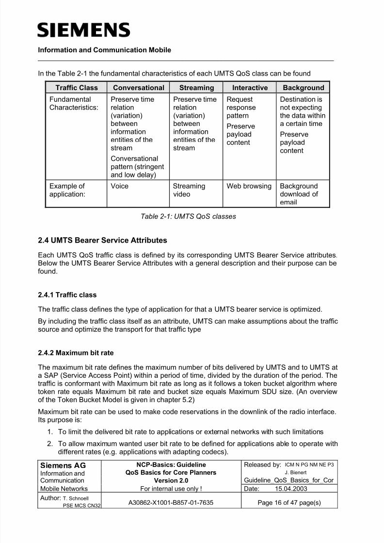
In the Table 2-1 the fundamental characteristics of each UMTS QoS class can be found
Traffic Class Conversational Streaming Interactive Background
FundamentalCharacteristics:
Preserve timerelation(variation)betweeninformationentities of thestream
Conversationalpattern (stringentand low delay)
Preserve timerelation(variation)betweeninformationentities of thestream
Requestresponsepattern
Preservepayloadcontent
Destination isnot expectingthe data withina certain time
Preservepayloadcontent
Example of application:
Voice Streamingvideo
Web browsing Backgrounddownload of email
Table 2-1: UMTS QoS classes
2.4 UMTS Bearer Service Attributes
Each UMTS QoS traffic class is defined by its corresponding UMTS Bearer Service attributes.Below the UMTS Bearer Service Attributes with a general description and their purpose can befound.
2.4.1 Traffic class
The traffic class defines the type of application for that a UMTS bearer service is optimized.
By including the traffic class itself as an attribute, UMTS can make assumptions about the trafficsource and optimize the transport for that traffic type
2.4.2 Maximum bit rate
The maximum bit rate defines the maximum number of bits delivered by UMTS and to UMTS ata SAP (Service Access Point) within a period of time, divided by the duration of the period. Thetraffic is conformant with Maximum bit rate as long as it follows a token bucket algorithm wheretoken rate equals Maximum bit rate and bucket size equals Maximum SDU size. (An overviewof the Token Bucket Model is given in chapter 5.2)
Maximum bit rate can be used to make code reservations in the downlink of the radio interface.Its purpose is:
1. To limit the delivered bit rate to applications or external networks with such limitations
2. To allow maximum wanted user bit rate to be defined for applications able to operate withdifferent rates (e.g. applications with adapting codecs).

8/8/2019 QoS-Basics for Planners
http://slidepdf.com/reader/full/qos-basics-for-planners 17/47
Information and Communication Mobile ____________________________________________________________________________________
Siemens AG NCP-Basics: Guideline Released by: ICM N PG NM NE P3
Information and QoS Basics for Core PlannersJ. Bienert
Communication Version 2.0 Guideline_QoS_Basics_for_Cor
Mobile Networks For internal use only ! Date: 15.04.2003
Author: T. Schnoell
PSE MCS CN32 A30862-X1001-B857-01-7635 Page 17 of 47 page(s)
2.4.3 Guaranteed bit rate
The Guaranteed bit rate defines the guaranteed number of bits delivered by UMTS at a SAP
within a period of time (provided that there is data to deliver), divided by the duration of theperiod. The traffic is conformant with the guaranteed bit rate as long as it follows a token bucketalgorithm where token rate equals Guaranteed bit rate and bucket size equals Maximum SDUsize.
UMTS bearer service attributes, e.g. delay and reliability attributes, are guaranteed for traffic upto the Guaranteed bit rate. For the traffic exceeding the Guaranteed bit rate the UMTS bearer service attributes are not guaranteed.
It describes the bit rate the UMTS bearer service shall guarantee to the user or application.Guaranteed bit rate may be used to facilitate admission control based on available resources,and for resource allocation within UMTS.
2.4.4 Delivery order
The Delivery order indicates whether the UMTS bearer shall provide in-sequence SDU deliveryor not.
The attribute is derived from the user protocol (PDP type) and specifies if out-of-sequenceSDUs are acceptable or not. This information cannot be extracted from the traffic class.Whether out-of-sequence SDUs are dropped or re-ordered depends on the specified reliability.
2.4.5 Maximum SDU size
The Maximum SDU size defines the maximum packet size for user payload.
It is used for admission control and policing.
2.4.6 SDU format information
The SDU format information provides a list of possible exact sizes of SDUs.
UTRAN needs SDU size information to be able to operate in transparent RLC protocol mode,which is beneficial to spectral efficiency and delay when RLC re-transmission is not used. Thus,if the application can specify SDU sizes, the bearer is less expensive.
2.4.7 SDU error ratio
The SDU error ratio indicates the fraction of SDUs lost or detected as erroneous. SDU error ratio is defined only for conforming traffic.
NOTE: By reserving resources, SDU error ratio performance is independent of the loadingconditions, whereas without reserved resources, such as in Interactive and Background classes,SDU error ratio is used as target value.

8/8/2019 QoS-Basics for Planners
http://slidepdf.com/reader/full/qos-basics-for-planners 18/47
Information and Communication Mobile ____________________________________________________________________________________
Siemens AG NCP-Basics: Guideline Released by: ICM N PG NM NE P3
Information and QoS Basics for Core PlannersJ. Bienert
Communication Version 2.0 Guideline_QoS_Basics_for_Cor
Mobile Networks For internal use only ! Date: 15.04.2003
Author: T. Schnoell
PSE MCS CN32 A30862-X1001-B857-01-7635 Page 18 of 47 page(s)
The SDU error ratio is used to configure the protocols, algorithms and error detection schemes,primarily within UTRAN.
2.4.8 Residual bit error ratio
The Residual bit error ratio indicates the undetected bit error ratio in the delivered SDUs. If noerror detection is requested, Residual bit error ratio indicates the bit error ratio in the deliveredSDUs.
The Residual bit error ratio is used to configure radio interface protocols, algorithms and error detection coding.
2.4.9 Delivery of erroneous SDUs
This indicates whether SDUs detected as erroneous shall be delivered or discarded.
The attribute Delivery of erroneous SDUs is used to decide whether error detection is neededand whether frames with detected errors shall be forwarded or not.
NOTE: The value “yes” implies that error detection is employed and that erroneous SDUs aredelivered together with an error indication; “no” implies that error detection is employed and thaterroneous SDUs are discarded; “-“ implies that SDUs are delivered without considering error detection.
2.4.10 Transfer delay
The Transfer delay indicates maximum delay for 95th percentile of the distribution of delay for all delivered SDUs during the lifetime of a bearer service, where delay for an SDU is defined asthe time from a request to transfer an SDU at one SAP1 to its delivery at the other SAP.
The Transfer delay is used to specify the delay tolerated by the application. It allows UTRAN toset transport formats and ARQ2 (Automatic Repeat Request) parameters.
NOTE: Transfer delay of an arbitrary SDU is not meaningful for a bursty source, since the lastSDUs of a burst may have long delay due to queuing, whereas the meaningful response delayperceived by the user is the delay of the first SDU of the burst.
2.4.11 Traffic handling priority
The Traffic handling priority specifies the relative importance for handling of all SDUs belongingto the UMTS bearer compared to the SDUs of other bearers.
1 A Bearer Service might represent a SAP (Service Access Point)
2 UTRAN specific parameter

8/8/2019 QoS-Basics for Planners
http://slidepdf.com/reader/full/qos-basics-for-planners 19/47
Information and Communication Mobile ____________________________________________________________________________________
Siemens AG NCP-Basics: Guideline Released by: ICM N PG NM NE P3
Information and QoS Basics for Core PlannersJ. Bienert
Communication Version 2.0 Guideline_QoS_Basics_for_Cor
Mobile Networks For internal use only ! Date: 15.04.2003
Author: T. Schnoell
PSE MCS CN32 A30862-X1001-B857-01-7635 Page 19 of 47 page(s)
Within the interactive class, there is a definite need to differentiate between bearer qualities.This is handled by using the traffic handling priority attribute, to allow UMTS to schedule trafficaccordingly.
2.4.12 Allocation/Retention priority
The Allocation/Retention priority specifies the relative importance compared to other UMTSbearers for allocation and retention of the UMTS bearer. The Allocation/Retention Priorityattribute is a subscription attribute, which is not negotiated from the mobile terminal.
Priority is used for differentiating between bearers when performing allocation and retention of abearer. In situations where resources are scarce, the relevant network elements can use theAllocation/Retention Priority to prioritize bearers with a high Allocation/Retention Priority over bearers with a low Allocation/Retention Priority when performing admission control.
NOTE: The addition of a user-controlled Allocation/Retention Priority attribute is for further studyin future releases.
2.4.13 Traffic classes and values for their corresponding attributes
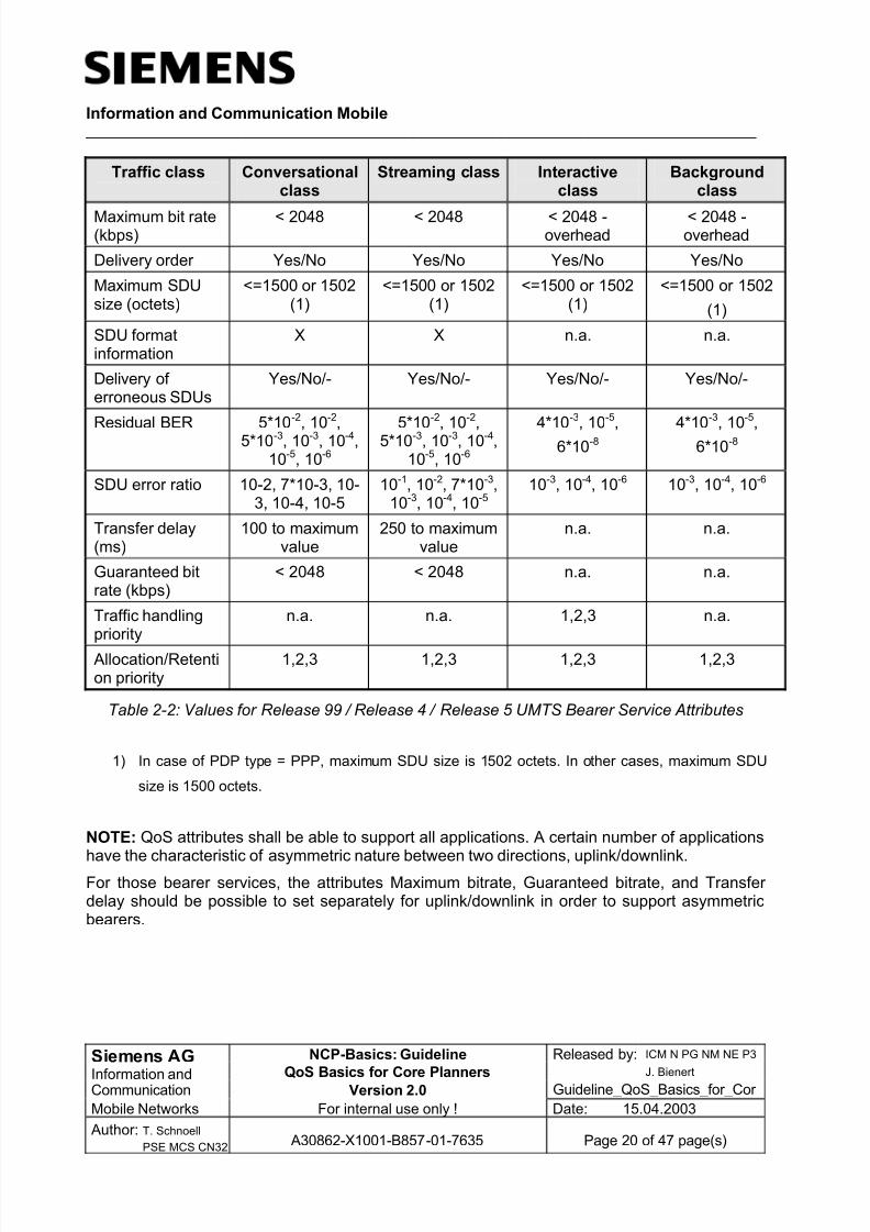
In the table below the value ranges of the UMTS Bearer Service attributes are listed. The valueranges reflect the capability of UMTS network.
8/8/2019 QoS-Basics for Planners
http://slidepdf.com/reader/full/qos-basics-for-planners 20/47
Information and Communication Mobile ____________________________________________________________________________________
Siemens AG NCP-Basics: Guideline Released by: ICM N PG NM NE P3
Information and QoS Basics for Core PlannersJ. Bienert
Communication Version 2.0 Guideline_QoS_Basics_for_Cor
Mobile Networks For internal use only ! Date: 15.04.2003
Author: T. Schnoell
PSE MCS CN32 A30862-X1001-B857-01-7635 Page 20 of 47 page(s)
Traffic class Conversationalclass
Streaming class Interactiveclass
Backgroundclass
Maximum bit rate(kbps)
< 2048 < 2048 < 2048 -overhead
< 2048 -overhead
Delivery order Yes/No Yes/No Yes/No Yes/No
Maximum SDUsize (octets)
<=1500 or 1502(1)
<=1500 or 1502(1)
<=1500 or 1502(1)
<=1500 or 1502
(1)
SDU formatinformation
X X n.a. n.a.
Delivery of erroneous SDUs
Yes/No/- Yes/No/- Yes/No/- Yes/No/-
Residual BER 5*10-2, 10-2,5*10-3, 10-3, 10-4,
10-5, 10-6
5*10-2, 10-2,5*10-3, 10-3, 10-4,
10-5, 10-6
4*10-3, 10-5,
6*10-8
4*10-3, 10-5,
6*10-8
SDU error ratio 10-2, 7*10-3, 10-3, 10-4, 10-5
10-1, 10-2, 7*10-3,10-3, 10-4, 10-5
10-3, 10-4, 10-6 10-3, 10-4, 10-6
Transfer delay(ms)
100 to maximumvalue
250 to maximumvalue
n.a. n.a.
Guaranteed bitrate (kbps)
< 2048 < 2048 n.a. n.a.
Traffic handlingpriority
n.a. n.a. 1,2,3 n.a.
Allocation/Retention priority
1,2,3 1,2,3 1,2,3 1,2,3
Table 2-2: Values for Release 99 / Release 4 / Release 5 UMTS Bearer Service Attributes
1) In case of PDP type = PPP, maximum SDU size is 1502 octets. In other cases, maximum SDU
size is 1500 octets.
NOTE: QoS attributes shall be able to support all applications. A certain number of applications
have the characteristic of asymmetric nature between two directions, uplink/downlink.For those bearer services, the attributes Maximum bitrate, Guaranteed bitrate, and Transfer delay should be possible to set separately for uplink/downlink in order to support asymmetricbearers.
8/8/2019 QoS-Basics for Planners
http://slidepdf.com/reader/full/qos-basics-for-planners 21/47
Information and Communication Mobile ____________________________________________________________________________________
Siemens AG NCP-Basics: Guideline Released by: ICM N PG NM NE P3
Information and QoS Basics for Core PlannersJ. Bienert
Communication Version 2.0 Guideline_QoS_Basics_for_Cor
Mobile Networks For internal use only ! Date: 15.04.2003
Author: T. Schnoell
PSE MCS CN32 A30862-X1001-B857-01-7635 Page 21 of 47 page(s)
2.5 QoS Negotiation
The QoS negotiation takes place during the PDP context activation or modification.
The task of the QoS negotiation is check what QoS the user is allowed to request respectivelywhat QoS the network is able to provide to the user. Furthermore for Real Time Context aresource reservation takes place.
Since it is possible that the user request a higher QoS than he is allowed or the network is notable to provided the requested QoS, the requested QoS of the User can be downgraded.
For the QoS negotiation 3 QoS profiles are required that include the UMTS QoS attributes:
• Requested QoS profileThe Requested QoS Profile specifies the QoS requested by the user during PDP ContextActication/Modification. For each parameter of the QoS profile, the mobile station caneither set a specific value or can select the subscribed parameter to be used. It isincluded in the PDP Context Activation/Modification message sent from the UE to theSGSN.
• Subscribed QoS profileThe Subscribed QoS profile reflects the highest QoS values the subscriber is allowed touse. This profile is stored in the HLR and is transferred to the SLR/SGSN after attachprocedure. The Subscribed QoS profile defines the maximum QoS per PDP context per associated APN. It is used to check the QoS parameters contained within the RequestedQoS profile
• Negotiated QoS profileThe result of the negotiation within each node is the Negotiated QoS profile that is sent to
the next node for negotiation in the QoS negotiation sequence. In the end the NegotiatedQoS Profile is sent back to the user to inform what QoS its activated Context supports.The finally Negotiated QoS Profile represents on the one hand the allowed QoS of theuser on the other hand it represent also the the capability of each involved networkelement (SGSN, GGSN RNC or BSC and MS) to serve the requested QoS.
2.5.1 QoS negotiation and Resource Reservation Sequence
As described above a negotiation of the QoS attributes requested by the UE within theRequested QoS Profile takes place during PDP context activation/modification.
Each network element within the user data path (SGSN, GGSN, BSC/RNC) is involved in the
QoS negotiation when the mobile station requests a particular QoS.
The SGSN is the first Node that receives QoS attributes of the UE (e.g. in PDP Context Requestmessage). The QoS attributes included in this message represent the Requested QoS Profile.The SGSN performs Subscription and Admission/Capability Control. Therefore it compares theRequested QoS Profile with the Subscribed Profile that was downloaded from the HLR to theSLR during the Attach phase.
The result of the Subscription Check and Admission/Capability Control of the SGSN is aNegotiated QoS Profile that is forwarded within the “Create PDP Context Request” message tothe GGSN that has further the possibility to negotiate the Negotiated QoS Profile of the SGSN

8/8/2019 QoS-Basics for Planners
http://slidepdf.com/reader/full/qos-basics-for-planners 22/47
Information and Communication Mobile ____________________________________________________________________________________
Siemens AG NCP-Basics: Guideline Released by: ICM N PG NM NE P3
Information and QoS Basics for Core PlannersJ. Bienert
Communication Version 2.0 Guideline_QoS_Basics_for_Cor
Mobile Networks For internal use only ! Date: 15.04.2003
Author: T. Schnoell
PSE MCS CN32 A30862-X1001-B857-01-7635 Page 22 of 47 page(s)
during its Admission/Capability Control. Furthermore also in the GGSN Resource Reservationfor Real Time Contexts takes place.
The Negotiated Profile of the GGSN is sent back to the SGSN in the “Create PDP ContextResponse” message and further forwarded the RNC in the “RAB Assignment Request”message that also has the possibility the negotiated the QoS profile.
The RNC sends the Negotiated Profile back to the SGSN in the RAB Assignment Responsemessage. If a downgrade of the QoS attributes has taken place an update takes place.
In the end the final Negotiated QoS Profile is sent from the SGSN to the UE in the PDP ContextActivation Response message.
NOTE: QoS negotiation always means keeping or downgrading of the attributes included in theQoS Profile.
UE RNC SGSN GGSN
Activate_PDP_C_Req (QoS Req)
Create_PDP_C_Req (QoS Neg)
Create_PDP_C_Resp (QoS Neg)
RAB_Assign_Req (QoS Neg)
RAB_Assign_Resp (QoS Neg)
Activate_PDP_C_Acc (QoS Neg)
Sub. Check
Adm/Cap
Control
Resource
Reservation
Optional: Update
Adm/Cap
Control
Resource
Reservation
Figure 2-4: QoS negotiation sequence
The QoS negotiation takes place within the nodes. No QoS negotiation with the connectednetworks takes place. Therefore, it has to be ensured during planning and dimensioning phaseof the networks that the traffic within the networks can be supported according to the QoSrequirements of the traffic.

8/8/2019 QoS-Basics for Planners
http://slidepdf.com/reader/full/qos-basics-for-planners 23/47

8/8/2019 QoS-Basics for Planners
http://slidepdf.com/reader/full/qos-basics-for-planners 24/47
Information and Communication Mobile ____________________________________________________________________________________
Siemens AG NCP-Basics: Guideline Released by: ICM N PG NM NE P3
Information and QoS Basics for Core PlannersJ. Bienert
Communication Version 2.0 Guideline_QoS_Basics_for_Cor
Mobile Networks For internal use only ! Date: 15.04.2003
Author: T. Schnoell
PSE MCS CN32 A30862-X1001-B857-01-7635 Page 24 of 47 page(s)
3.1 UMTS bearer service scenarios
According to [3GPP_23.107] the QoS attribute mapping from application attributes to the UMTS
bearer is 'an operator and/or implementation' issue. The number and type of UMTS bearer services is limited. Therefore the E2E service requirements of applications have to be mappedto UMTS bearer services. The main bottleneck in terms of resources in a PLMN is the air interface and the access network. Therefore radio access network planning should decide onthis mapping.
Additionally to the selection of traffic class attributes have to be derived. The result of thisplanning phase is:
• A list of supported applications including expected traffic per application and applicationrequirements.
• A list of supported QoS profiles.
• A mapping of applications to QoS profiles.
Within the radio access traffic can be differentiated based on the mapping granularity above.Since the traffic aggregation is much higher in the core network these classes can be further aggregated efficiently at the Backbone bearer service level (see below).
Example:
To support low and high quality video conferencing and Internet applications in generalwe decide to implement five different QoS profiles. The video conferencing applicationsuse QoS Profiles with the Traffic class Conversational the with 128 kBit/s and 384 kBit/sguaranteed bit rate. All Internet applications use the Traffic class Interactive with varyingTraffic handling priority(1,2,3) that enables additional 3 QoS profiles. The selection of a
traffic handling priority does not depend on the application. For instance this could bedetermined by user subscription information.
Some of the QoS attributes define mandatory technical requirements. Applications will fail if these requirements are not met. But some of the attributes can also be used to differentiateservice perception of a user. E.g. web browsing is possible with any traffic handling priority. Inthis case a QoS attribute is used to implement different classes of users. And finally, for corenetwork planning only some of the UMTS bearer service attributes are of relevance. Table 3-1lists all attributes.
3.2 CN bearer service scenarios
The SGSN has to implement the mapping function of the CN bearer service to the Radioaccess- and Iu bearer service.
The GGSN has to implement the mapping function of the UMTS bearer service to the Externalbearer service at the Gi-interface. The External bearer service itself is not standardized.Network scenarios and the mapping of service attributes for External Bearer Services are out of scope of this document.
The role of the CN bearer service is to connect the UMTS bearer service with Backbone bearer services.

8/8/2019 QoS-Basics for Planners
http://slidepdf.com/reader/full/qos-basics-for-planners 25/47
Information and Communication Mobile ____________________________________________________________________________________
Siemens AG NCP-Basics: Guideline Released by: ICM N PG NM NE P3
Information and QoS Basics for Core PlannersJ. Bienert
Communication Version 2.0 Guideline_QoS_Basics_for_Cor
Mobile Networks For internal use only ! Date: 15.04.2003
Author: T. Schnoell
PSE MCS CN32 A30862-X1001-B857-01-7635 Page 25 of 47 page(s)
3.2.1 Mapping of CN bearer service attributes
According to [3GPP_23.107] (this will not change up to at least Release 5) the QoS attribute
mapping with respect to the CN bearer is 'an operator and/or implementation' issue. In thefollowing we describe the planning of such mappings.
3.2.2 From UMTS bearer service attributes to CN bearer service attributes
The two core network nodes SGSN and GGSN are entities that are involved in processing of UMTS bearer services attributes. The BG does not implement any UMTS bearer servicefunctions. Information between SGSN and GGSN regarding QoS is exchanged using the GTP-C protocol. The UMTS bearer service attributes that are relevant for the CN bearer service aregiven in the table below.
Traffic class Conversational Streaming Interactive BackgroundAllocation / Retention priority X X X X
Traffic handling priority - - X -
Maximum bit rate X X X X
Guaranteed bit rate X X - -
Transfer delay X X - -
SDU error rate X X X X
Table 3-1: UMTS bearer service attributes relevant for CN bearer service
The SGSN and GGSN implement control functions that actively enforce QoS profiles. Theattributes have the following influence to core network planning.
• Traffic classThe selection of the traffic class depends only on application requirements. For corenetwork nodes (especially SGSN) the percentage of traffic in the Traffic classesConversational and Streaming is limited.
• Allocation/Retention prioritySGSN and GGSN use this attribute to prioritize the establishment of contexts within thenetwork nodes.
• Traffic handling priorityThis attribute is used only to differentiate Interactive traffic in case of overload situations.
The selection of the traffic handling priority is not driven by application requirements butby the service model.
• Maximum bit rateIn the core network the maximum downlink bit rate is actively controlled at the GGSN by apolicy function that shapes traffic per PDP context. This has influence to linkdimensioning but does not affect the planning of bearer scenarios in the core network.
• Guaranteed bit rateThis attribute is defined only for Streaming and Conversational traffic.

8/8/2019 QoS-Basics for Planners
http://slidepdf.com/reader/full/qos-basics-for-planners 26/47
Information and Communication Mobile ____________________________________________________________________________________
Siemens AG NCP-Basics: Guideline Released by: ICM N PG NM NE P3
Information and QoS Basics for Core PlannersJ. Bienert
Communication Version 2.0 Guideline_QoS_Basics_for_Cor
Mobile Networks For internal use only ! Date: 15.04.2003
Author: T. Schnoell
PSE MCS CN32 A30862-X1001-B857-01-7635 Page 26 of 47 page(s)
• Transfer delayIt is only relevant for Streaming and Conversational traffic. It is not only the time it takes toforward packets and transfer packets over links but includes also the time needed tobuffer packets and remove delay variations. Due to the high bandwidths and wire speedrouters delay variation is the main portion of delay in the core network.
• SDU error rateThe error rate is not explicitly controllable within the core network. It serves as adimensioning goal. The actual value achieved in the core network must be one or twoorder of magnitudes lower than the negotiated value. In other words, all but a negligibleamount of SDU-errors must occur in the radio access network.
Note: In principal one of the real time classes (Conversational, Streaming) can be used by theUE to carry non-real time traffic. In that case the packet loss demands of non-real time trafficmust be taken into account. Packet loss demands of non-real time services are generally higher
than packet loss demands for real time services!
3.3 Backbone bearer service scenarios
According to [3GPP_23.107] the QoS attribute mapping from CN bearer service to Backbonebearer service is 'an operator and/or implementation' issue. The Backbone bearer is an IPnetwork that must be able to fulfill QoS requirements. This can be achieved by means of one of the following techniques:
• Over provisioning (reserve 'enough' bandwidth)
• DiffServ
• MPLS (DiffServ respectively Traffic Engineering)
• IP over ATM
Other IP QoS mechanisms are currently not considered.
3.3.1 From CN bearer service attributes to Backbone bearer service attributes
The Backbone bearer service does not directly implement any UMTS bearer service functions.Based on the QoS architecture of the Backbone bearer service (DiffServ, ATM, etc.) we have tofind a mapping that fulfills the QoS requirements. In UMTS Release 4 no interworkingmechanisms to dynamically negotiate QoS (e.g. to implement call access control) between a
core network node and the backbone nodes are standardized.Therefore the following attributes are relevant for the Backbone bearer service:
• Traffic class: Background, Interactive, Streaming, and Conversational.
• Maximum bit rate: up to 2048Kbit/s.
• Guaranteed bit rate: up to 2048Kbit/s, only for Streaming and Conversational traffic.
• Transfer delay: only for Streaming and Conversational traffic.
• Traffic handling priority: only for Interactive traffic.

8/8/2019 QoS-Basics for Planners
http://slidepdf.com/reader/full/qos-basics-for-planners 27/47

8/8/2019 QoS-Basics for Planners
http://slidepdf.com/reader/full/qos-basics-for-planners 28/47
Information and Communication Mobile ____________________________________________________________________________________
Siemens AG NCP-Basics: Guideline Released by: ICM N PG NM NE P3
Information and QoS Basics for Core PlannersJ. Bienert
Communication Version 2.0 Guideline_QoS_Basics_for_Cor
Mobile Networks For internal use only ! Date: 15.04.2003
Author: T. Schnoell
PSE MCS CN32 A30862-X1001-B857-01-7635 Page 28 of 47 page(s)
4 QoS mechanisms
In this chapter the basic of four possible QoS mechanisms are described.
4.1 Over Provisioning
Over-provisioning leans on the fact that with enough available bandwidth any amount of trafficcan be supported. The problem with this method can be seen in not being able to control theamount of traffic within the network furthermore it can not be aggregation of traffic can not becontrolled within the network which could lead to an overload of links.
At the edge of a network that performs over provisioning the incoming traffic has to be shaped.
4.2 DiffServ
At DiffServ model, the traffic that enters a network is first classified and then possiblyconditioned at the edges of the DS network. Depending on the result of the packet classificationprocess, each packet is associated with one of the Behavior Aggregates (BAs) supported by theDifferentiated Services domain. The BA that each packet is assigned to is indicated by thespecific value carried in the DSCP bits of the DS Field. When a packet enters the core of thenetwork, each router along the transit path applies the appropriate Per Hop Behavior (PHB),based on the DSCP carried in the packet's header.
The complete DiffServ architecture is defined in [RFC2475].
4.2.1 General
A Differentiated Services domain (DS domain) is a contiguous set of routers that operate withcommon sets of service provisioning policies and PHB group definitions.
DS domain consists of DS boundary nodes and DS interior nodes.
• The DS ingress boundary router generally performs Multi-Field (MF) packet classification(means based on a combination of the values of one or more IP-header fields) and trafficconditioning functions (metering, (re)marking, shaping and dropping).
A DS ingress boundary router can also apply the appropriate PHB, based on the result of this packet classification process. A DS ingress boundary router may also perform BApacket classification (means classification based on the already included DSCP) if ittrusts an upstream DS domain’s packet classification.
The DS egress boundary router normally performs traffic shaping as packets leave theDS domain for another DS domain or non-DS-capable domain. A DS egress boundaryrouter may also perform MF or BA packet classification and precedence rewriting if it hasan agreement with a downstream DS domain.
• A DS interior router usually performs BA packet classification to associate each packetwith a behavior aggregate. It then applies the appropriate PHB by using specific buffer-

8/8/2019 QoS-Basics for Planners
http://slidepdf.com/reader/full/qos-basics-for-planners 29/47
Information and Communication Mobile ____________________________________________________________________________________
Siemens AG NCP-Basics: Guideline Released by: ICM N PG NM NE P3
Information and QoS Basics for Core PlannersJ. Bienert
Communication Version 2.0 Guideline_QoS_Basics_for_Cor
Mobile Networks For internal use only ! Date: 15.04.2003
Author: T. Schnoell
PSE MCS CN32 A30862-X1001-B857-01-7635 Page 29 of 47 page(s)
management and packet-scheduling mechanisms to support the specific packet-forwarding treatment.
DS Interior
Node
DS Interior
Node
DS Ingress
Boundary Node
DS Egress
Boundary Node
BA-Classification
MF-Classification
BA-Classification BA-Classification
MF-Classification
BA-Classification
Figure 4-1: General DiffServ network
4.2.1.1 Differentiated Service Router Functions
The figure below provides a logical view of the operation of a packet classifier and trafficconditioner on a DiffServ-capable router.
Packet
Classifier Marker
Shaper /
Dropper
Meter
Traffic Conditioner
Figure 4-2: Classification and traffic conditioner function
The DiffServ architecture defines two types of packet classifiers:
• A BA-classifier selects packets based on the value of the DSCP only.
• A MF-classifier selects packets based on a combination of the values of one or moreIP-header fields.
A Traffic Conditioner may consist of various elements that perform traffic metering, marking,shaping, and dropping. A traffic conditioner is not required to support all of these functions.
• Meter A meter measures a traffic stream to determine whether a particular packet from thestream is in-profile or out-of-profile. The meter passes the in-profile or out-of-profile state
8/8/2019 QoS-Basics for Planners
http://slidepdf.com/reader/full/qos-basics-for-planners 30/47
Information and Communication Mobile ____________________________________________________________________________________
Siemens AG NCP-Basics: Guideline Released by: ICM N PG NM NE P3
Information and QoS Basics for Core PlannersJ. Bienert
Communication Version 2.0 Guideline_QoS_Basics_for_Cor
Mobile Networks For internal use only ! Date: 15.04.2003
Author: T. Schnoell
PSE MCS CN32 A30862-X1001-B857-01-7635 Page 30 of 47 page(s)
information to other traffic conditioning elements so that different conditioning actions canbe applied to in-profile and out-of-profile packets.
•
Maker A marker writes (or rewrites) the DS Field of a packet header to a specific DSCP, so thatthe packet is assigned to a particular DS behavior aggregate.
• Shaper A shaper delays some or all packets in a traffic stream to bring the stream intoconformance with its traffic profile.
• Dropper A dropper (policer) discards some or all packets in a traffic stream to bring the stream intoconformance with its traffic profile.
4.2.1.2 Applicable PHB Groups
A per-hop behavior (PHB) is a description of the externally observable forwarding behavior applied to a particular behavior aggregate. The PHB is the means by which a DS node allocatesits resources to different behavior aggregates. The DiffServ architecture supports the delivery of scalable service discrimination, based on this hop-by-hop resource allocation mechanism.
PHBs are defined in terms of the behavior characteristics that are relevant to a provider'sservice provisioning policies. A specific PHB may be defined in terms of:
• The amount of resources allocated to the PHB (buffer size and link bandwidth),
• The relative priority of the PHB compared with other PHBs, or
• The observable traffic characteristics (delay, jitter, and loss).However, PHBs are not defined in terms of specific implementation mechanisms. Consequently,a variety of different implementation mechanisms may be acceptable for implementing a specificPHB group. Following PHB are existing:
• Default PHB (Best Effort; standard IP)
• Assured forwarding PHB
• Expedited forwarding PHB
The 3 different PHB can occur within one network, which enables a distribution of traffic on the3 PHBs.
4.2.1.2.1 Assured forwarding
The Assured Forwarding (AF) PHB group is designed to ensure that packets are forwarded witha high probability, as long as the aggregate traffic in a forwarding class does not exceed thesubscribed information rate. If ingress traffic exceeds its subscribed information rate, the out-of-profile traffic is not delivered with as high a probability as traffic that is in-profile.

8/8/2019 QoS-Basics for Planners
http://slidepdf.com/reader/full/qos-basics-for-planners 31/47
Information and Communication Mobile ____________________________________________________________________________________
Siemens AG NCP-Basics: Guideline Released by: ICM N PG NM NE P3
Information and QoS Basics for Core PlannersJ. Bienert
Communication Version 2.0 Guideline_QoS_Basics_for_Cor
Mobile Networks For internal use only ! Date: 15.04.2003
Author: T. Schnoell
PSE MCS CN32 A30862-X1001-B857-01-7635 Page 31 of 47 page(s)
The AF PHB group includes four traffic classes. Packets within each AF class can be markedwith one of three possible drop-precedence values. The AF PHB group can be used toimplement Olympic-style service that consists of three service classes3:
• Gold (e.g. AF Class1)
• Silver (e.g. AF Class 2)
• Bronze (e.g. AF Class 3)
For the differentiation of packets within a certain AF class, to each packet a certain dropprecedence value can be assigned. The Table 4-1 summarizes the recommended DSCPs of the four AF PHB.
AF Class 1 AF Class 2 AF Class 3 AF Class 4
Low drop precedence 001010 010010 011010 100010
Medium drop precedence 001100 010100 011100 100100
High drop precedence 001110 010110 011110 100110
Table 4-1: AF classes and corresponding DSCP values
4.2.1.2.2 Expedited forwarding PHB
According to the IETF's DiffServ Working Group, the Expedited Forwarding (EF) PHB isdesigned to provide "low loss, low delay, low jitter, assured bandwidth, end-to-end service." Ineffect, the EF PHB simulates a virtual leased line to support highly reliable voice or video and toemulate dedicated circuit services. The recommended DSCP for the EF PHB is 101110.
Since the only aspect of delay that you can control in your network is the queuing delay, youcan minimize both delay and jitter when you minimize queuing delays. Thus, the intent of the EFPHB is to arrange that suitably marked packets encounter extremely short or empty queues toensure minimal delay and jitter. You can achieve this only if the service rate for EF packets on agiven output port exceeds the usual rate of packet arrival at that port, independent of the loadon other (non-EF) PHBs.
4.3 MPLS
MPLS is defined in the [RFC3031] . A description of the basic functionality of MPLS can be
found in the document [IP_Basics]. This document describes how QoS can be enabled with thehelp of MPLS. Therefore it is focused on two mechanisms:
• Traffic Engineering
• MPLS and DiffServ interworking
3 The IETF approach realizes the Olympic service with the help of the different AF classes. The QoS
appracoch of 3GPP realizes the differentiation of services within the Traffic class Interactive with the help
of the different drop precedence values.

8/8/2019 QoS-Basics for Planners
http://slidepdf.com/reader/full/qos-basics-for-planners 32/47
Information and Communication Mobile ____________________________________________________________________________________
Siemens AG NCP-Basics: Guideline Released by: ICM N PG NM NE P3
Information and QoS Basics for Core PlannersJ. Bienert
Communication Version 2.0 Guideline_QoS_Basics_for_Cor
Mobile Networks For internal use only ! Date: 15.04.2003
Author: T. Schnoell
PSE MCS CN32 A30862-X1001-B857-01-7635 Page 32 of 47 page(s)
4.3.1 Traffic Engineering
The purpose of traffic engineering (TE) is to balance the traffic load on the various links, routers
and switches in the network so that none of these components are over- or underutilized. Trafficengineering allows an Internet Service Provider to fully exploit its network infrastructure.
One method to support TE within a network is MPLS is with the help of RSVP-TE as labeldistribution protocol. RSVP-TE is defined in [RFC3209] .
The task of this protocol is among other things like label distribution, to initiate resourcereservation for an LSP. For that reason additional parameters are required, which describe thetraffic in technical detail. For RSVP-TE this will be done with the help of the TSpec (for additional information please refer to [RFC2205] ) for instance.
RSVP-TE is useful for TE since explicit routing is possible. This means that the path through thenetwork will be determined at the beginning of resource reservation (means end-to-end) and not
hop-by-hop like in the normal IP infrastructure.
4.3.2 MPLS and DiffServ
At the MPLS DiffServ interworking [RFC3270] the DSCP of the incoming packet will be used toassign the correct label. For this mechanism two methods exist
• L-LSPWith this method the whole service class is inferred from the label itself. Each PHB isassigned to a different LSP. The establishment of the LSP is done with the help of enhanced signaling, which takes both address-prefix in the FEC and different PHB inconsideration.
Packets of different classes are transmitted via separate LSPs and are also stored inseparate queues.
• E-LSPFor this method there are only 8 different service classes defined. The DSCP of thepacket can be assigned to the EXP field of MPLS Shim Header and vice versa.For the transmission of data only one LSP is required. Packets of different classes aretransmitted on the same LSP but are stored in different queues depending on their EXP.For E-LSP no additional signaling is required, therefore E-LSP does not interwork withATM or Frame Relay
For the DiffServ support within MPLS networks actually only draft exist, which give a generaloverview about this topic. Since some producer of router equipment have alreadyimplemented similar mechanism, it should always attention be paid to the implementation of each producer.

8/8/2019 QoS-Basics for Planners
http://slidepdf.com/reader/full/qos-basics-for-planners 33/47
Information and Communication Mobile ____________________________________________________________________________________
Siemens AG NCP-Basics: Guideline Released by: ICM N PG NM NE P3
Information and QoS Basics for Core PlannersJ. Bienert
Communication Version 2.0 Guideline_QoS_Basics_for_Cor
Mobile Networks For internal use only ! Date: 15.04.2003
Author: T. Schnoell
PSE MCS CN32 A30862-X1001-B857-01-7635 Page 33 of 47 page(s)
4.4 ATM QoS
For the support of QoS within ATM network 4 different ATM service classes are defined.
4.4.1 ATM QoS Service Classes
• Constant Bit Rate (CBR)This traffic class supports the transmission of a constant bit stream. The ATM Switchesreserve a fixed bandwidth for the duration of the connection. This Service class can beused for voice and video applications.
• Variable Bit Rate (VBR)The VBR traffic class supports applications, which require dynamic bit rates (Burst). TheATM switches guarantee an average bit rate and are able to handle short traffic bursts.
The VBR traffic class can be distinguished between VBT-RT, which supports connectionswith a fixed timing relationship and the NRT-VBR for non-time critical connections.
• Variable Bit Rate - Real Time (VBR-RT)The real time VBR service class is intended for real-time applications, i.e., thoserequiring tightly constrained delay and delay variation, as would be appropriate for voice and video applications. Sources are expected to transmit at a rate, which varieswith time. Equivalently the source can be described "bursty". Cells, which are delayedbeyond the value specified by CTD are assumed to be of significantly less value to theapplication. Real-time VBR service may support statistical multiplexing of real-timesources, or may provide a consistently guaranteed QoS.
• Variable Bit Rate - Non-Real Time (VBR-NRT)
The non-real time VBR service class is intended for non-real time applications whichhave “bursty” traffic characteristics and which can be characterized in terms of a GCRA(Generic Cell Rate Algorithm). For those cells, which are transferred, it expects abound on the cell transfer delay. Non-real time VBR service supports statisticalmultiplexing of connections.
• Available Bit Rate (ABR)Many applications have the ability to reduce their information transfer rate if the networkrequires them to do so. Likewise, they may wish to increase their information transfer rateif there is extra bandwidth available within the network. There may not be deterministicparameters because the users are willing to live with unreserved bandwidth. To supporttraffic from such sources in an ATM network will require facilities different from those for
Peak Cell Rate of Sustainable Cell Rate traffic. The ABR service is designed to fill thisneed.
• Unspecified Bit Rate (UBR)The UBR service class is intended for delay-tolerant or non-real-time applications e.g.those which do not require tightly constrained delay and delay variation, such astraditional computer communications applications. Sources are expected to transmit non-continuous bursts of cells. UBR service supports a high degree of statistical multiplexingamong sources. UBR service includes no notion of a per-VC allocated bandwidthresource. Transport of cells in UBR service is not necessarily guaranteed by mechanismsoperating at the cell level therefore no QoS parameter are specified for the UBR traffic.

8/8/2019 QoS-Basics for Planners
http://slidepdf.com/reader/full/qos-basics-for-planners 34/47
Information and Communication Mobile ____________________________________________________________________________________
Siemens AG NCP-Basics: Guideline Released by: ICM N PG NM NE P3
Information and QoS Basics for Core PlannersJ. Bienert
Communication Version 2.0 Guideline_QoS_Basics_for_Cor
Mobile Networks For internal use only ! Date: 15.04.2003
Author: T. Schnoell
PSE MCS CN32 A30862-X1001-B857-01-7635 Page 34 of 47 page(s)
However it is expected that resources will be provisioned for UBR service in such a wayas to make it usable for some set of applications. UBR service may be considered asinterpretation of the common term "best effort service".
4.4.2 ATM Traffic and QoS parameters
The ATM Service classes are specified with the help of the following parameters:
• Peak Cell Rate (PCR)This parameter characterizes the max. transfer rate for a virtual connection in cells/sec(respectively Bits/sec), which is required by a source.
• Minimum Cell Rate (MCR)This parameter specifies the minimum transfer rate for a virtual connection in cells/sec(respectively Bits/sec).
• Sustainable Cell Rate (SCR)This parameter specifies the average transfer rate. This parameter characterizes theburstiness of the source and is measured in Cell/sec respectively Bits/sec.
• Maximum Burst Size (MBS)This parameter specifies the maximum amount of cells that can briefly be transferred atthe PCR.
• Cell Delay Variation (CDV)The CDV specifies the difference between single cells transfer delay and the expectedtransfer delay. It gives a measure how closely cells are spaced in a virtual connection.The CDV is measured in µs.
• Cell Delay Variation Tolerance (CDVT)This parameter specifies the tolerance of the CDV.
• Cell Transfer Delay (CTD)This parameter specifies the average transfer time of a cell in a virtual connection. CTDincludes the coding, segmentation, reassembling, processing and the time in queues.The parameter is measured in µs or ms.
• Cell Loss Ratio (CLR)The CLR specifies the proportion of lost to transmitted cells.
In the Table 4-2 an allotment of the traffic parameter to the ATM service class is shown

8/8/2019 QoS-Basics for Planners
http://slidepdf.com/reader/full/qos-basics-for-planners 35/47
Information and Communication Mobile ____________________________________________________________________________________
Siemens AG NCP-Basics: Guideline Released by: ICM N PG NM NE P3
Information and QoS Basics for Core PlannersJ. Bienert
Communication Version 2.0 Guideline_QoS_Basics_for_Cor
Mobile Networks For internal use only ! Date: 15.04.2003
Author: T. Schnoell
PSE MCS CN32 A30862-X1001-B857-01-7635 Page 35 of 47 page(s)
Trafficparameter
CBR VBR-RT VBR-NRT ABR UBR
PCR X X X X -
MCR - - - X -
SCR - X X - -
MBS - X X - -
CDVT X X X - -
CDV X X - - -
CTD X X - - -
CLR X X X X -
Table 4-2: ATM Service classes and their parameters
4.4.3 Classical IP over ATM
In the classical IP over ATM approach the IP packets are transferred via PVCs (PermanentVirutal Circuits) respectively SVCs (Switched Virtual Circuits) within an ATM backbone. Theseare Layer 2 based logical connections between endpoints established by an administrator. Thetransmission of IP packets via ATM channels is done with the help of ATM adaptation layer 5.
The data transmission of IP packets via an ATM backbone requires a address resolution from IPaddress to ATM address for the SVC respectively PVC approach which is performed by anATMARP Server. For the data transfer via PVC at the Edge of the ATM network V-Router with
static configuration can be used for assigning IP packets to the corresponding PVC.
PVC
Router ATM
Switch
ATM
Switch
Router
VPI/VCI
VPI/VCIVPI/VCI
VPI/VCI
Admin.
Figure 4-3: ATM-PVC (Permanent Virtual Circuit)
For support of QoS a certain ATM service class has to be assigned to the PVC respectivelySVC.
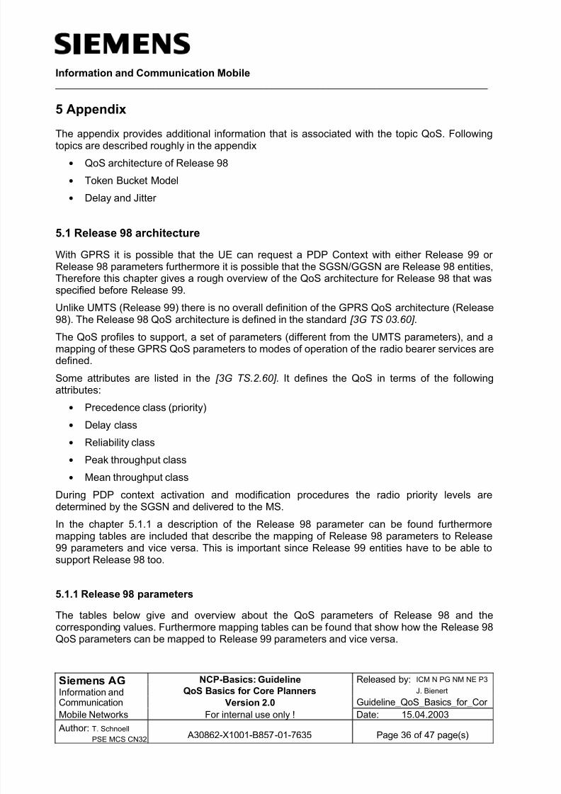
8/8/2019 QoS-Basics for Planners
http://slidepdf.com/reader/full/qos-basics-for-planners 36/47
Information and Communication Mobile ____________________________________________________________________________________
Siemens AG NCP-Basics: Guideline Released by: ICM N PG NM NE P3
Information and QoS Basics for Core PlannersJ. Bienert
Communication Version 2.0 Guideline_QoS_Basics_for_Cor
Mobile Networks For internal use only ! Date: 15.04.2003
Author: T. Schnoell
PSE MCS CN32 A30862-X1001-B857-01-7635 Page 36 of 47 page(s)
5 Appendix
The appendix provides additional information that is associated with the topic QoS. Followingtopics are described roughly in the appendix
• QoS architecture of Release 98
• Token Bucket Model
• Delay and Jitter
5.1 Release 98 architecture
With GPRS it is possible that the UE can request a PDP Context with either Release 99 or Release 98 parameters furthermore it is possible that the SGSN/GGSN are Release 98 entities,
Therefore this chapter gives a rough overview of the QoS architecture for Release 98 that wasspecified before Release 99.
Unlike UMTS (Release 99) there is no overall definition of the GPRS QoS architecture (Release98). The Release 98 QoS architecture is defined in the standard [3G TS 03.60] .
The QoS profiles to support, a set of parameters (different from the UMTS parameters), and amapping of these GPRS QoS parameters to modes of operation of the radio bearer services aredefined.
Some attributes are listed in the [3G TS.2.60] . It defines the QoS in terms of the followingattributes:
• Precedence class (priority)
• Delay class
• Reliability class
• Peak throughput class
• Mean throughput class
During PDP context activation and modification procedures the radio priority levels aredetermined by the SGSN and delivered to the MS.
In the chapter 5.1.1 a description of the Release 98 parameter can be found furthermoremapping tables are included that describe the mapping of Release 98 parameters to Release99 parameters and vice versa. This is important since Release 99 entities have to be able to
support Release 98 too.
5.1.1 Release 98 parameters
The tables below give and overview about the QoS parameters of Release 98 and thecorresponding values. Furthermore mapping tables can be found that show how the Release 98QoS parameters can be mapped to Release 99 parameters and vice versa.
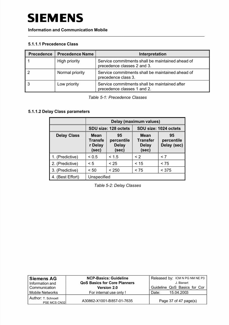
8/8/2019 QoS-Basics for Planners
http://slidepdf.com/reader/full/qos-basics-for-planners 37/47
Information and Communication Mobile ____________________________________________________________________________________
Siemens AG NCP-Basics: Guideline Released by: ICM N PG NM NE P3
Information and QoS Basics for Core PlannersJ. Bienert
Communication Version 2.0 Guideline_QoS_Basics_for_Cor
Mobile Networks For internal use only ! Date: 15.04.2003
Author: T. Schnoell
PSE MCS CN32 A30862-X1001-B857-01-7635 Page 37 of 47 page(s)
5.1.1.1 Precedence Class
Precedence Precedence Name Interpretation
1 High priority Service commitments shall be maintained ahead of precedence classes 2 and 3.
2 Normal priority Service commitments shall be maintained ahead of precedence class 3.
3 Low priority Service commitments shall be maintained after precedence classes 1 and 2.
Table 5-1: Precedence Classes
5.1.1.2 Delay Class parameters
Delay (maximum values)
SDU size: 128 octets SDU size: 1024 octets
Delay Class MeanTransfer Delay(sec)
95percentile
Delay(sec)
MeanTransfer
Delay(sec)
95percentileDelay (sec)
1. (Predictive) < 0.5 < 1.5 < 2 < 7
2. (Predictive) < 5 < 25 < 15 < 75
3. (Predictive) < 50 < 250 < 75 < 3754. (Best Effort) Unspecified
Table 5-2: Delay Classes

8/8/2019 QoS-Basics for Planners
http://slidepdf.com/reader/full/qos-basics-for-planners 38/47
Information and Communication Mobile ____________________________________________________________________________________
Siemens AG NCP-Basics: Guideline Released by: ICM N PG NM NE P3
Information and QoS Basics for Core PlannersJ. Bienert
Communication Version 2.0 Guideline_QoS_Basics_for_Cor
Mobile Networks For internal use only ! Date: 15.04.2003
Author: T. Schnoell
PSE MCS CN32 A30862-X1001-B857-01-7635 Page 38 of 47 page(s)
5.1.1.3 Reliability Class
Reliability
class
Lost SDU
probability(a)
Duplicate
SDUprobability
Out of
SequenceSDU
probability
Corrupt
SDUprobability
(b)
Example of application
characteristics.
110
-910
-910
-910
-9
Error sensitive, no error correction capability, limitederror tolerance capability.
210
-410
-510
-510
-6
Error sensitive, limited error correction capability, gooderror tolerance capability.
310
-210
-510
-510
-2
Not error sensitive, error correction capability and/or
very good error tolerancecapability.
Table 5-3: Reliability Classes – probabilities (in GSM 2.60)
ReliabilityClass
GTPMode
LLCFrameMode
LLC DataProtection
RLCBlockMode
Traffic Type
1 Ackn. Ackn. Prot. Ackn. Non real-time traffic, error-sensitive application thatcannot cope with data
loss.2 Unackn. Ackn. Prot. Ackn. Non real-time traffic, error-
sensitive application thatcan cope with infrequentdata loss.
3 Unackn. Unackn. Prot. Ackn. Non real-time traffic, error-sensitive application thatcan cope with data loss,GMM/SM, and SMS.
4 Unackn. Unackn. Prot. Unackn. Real-time traffic, error-sensitive application that
can cope with data loss.
5 Unackn. Unackn. Unprot. Unackn. Real-time traffic, error non-sensitive applicationthat can cope with dataloss.
NOTE: For real-time traffic, the QoS profile also requires appropriate settings for delay andthroughput.
Table 5-4: Reliability Classes –operation modes (in GSM 3.60)

8/8/2019 QoS-Basics for Planners
http://slidepdf.com/reader/full/qos-basics-for-planners 39/47
Information and Communication Mobile ____________________________________________________________________________________
Siemens AG NCP-Basics: Guideline Released by: ICM N PG NM NE P3
Information and QoS Basics for Core PlannersJ. Bienert
Communication Version 2.0 Guideline_QoS_Basics_for_Cor
Mobile Networks For internal use only ! Date: 15.04.2003
Author: T. Schnoell
PSE MCS CN32 A30862-X1001-B857-01-7635 Page 39 of 47 page(s)
5.1.1.4 Peak Throughput class
Peak Throughput Class Peak Throughput in octets per second
1 Up to 1 000 (8 kbit/s).
2 Up to 2 000 (16 kbit/s).
3 Up to 4 000 (32 kbit/s).
4 Up to 8 000 (64 kbit/s).
5 Up to 16 000 (128 kbit/s).
6 Up to 32 000 (256 kbit/s).
7 Up to 64 000 (512 kbit/s).
8 Up to 128 000 (1 024 kbit/s).
9 Up to 256 000 (2 048 kbit/s).
Table 5-5: Peak Throughput Classes
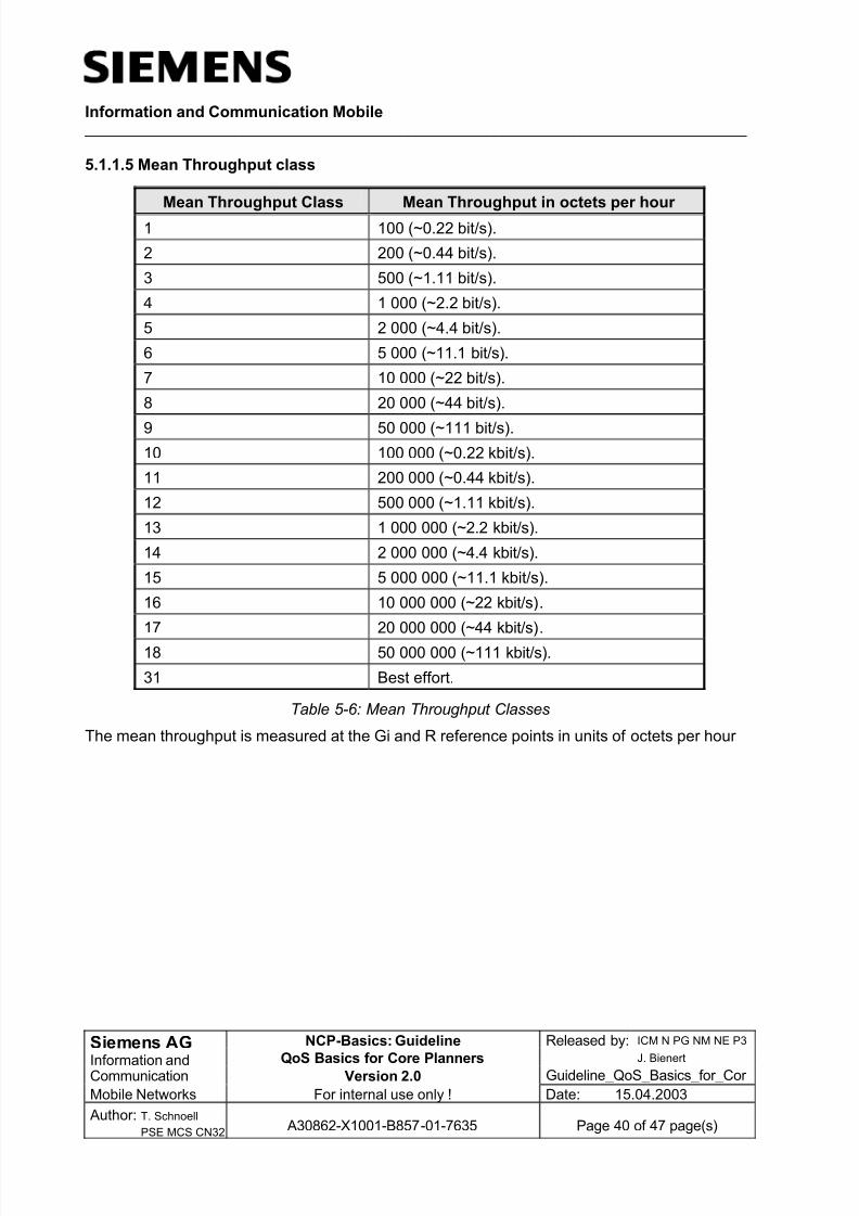
8/8/2019 QoS-Basics for Planners
http://slidepdf.com/reader/full/qos-basics-for-planners 40/47
Information and Communication Mobile ____________________________________________________________________________________
Siemens AG NCP-Basics: Guideline Released by: ICM N PG NM NE P3
Information and QoS Basics for Core PlannersJ. Bienert
Communication Version 2.0 Guideline_QoS_Basics_for_Cor
Mobile Networks For internal use only ! Date: 15.04.2003
Author: T. Schnoell
PSE MCS CN32 A30862-X1001-B857-01-7635 Page 40 of 47 page(s)
5.1.1.5 Mean Throughput class
Mean Throughput Class Mean Throughput in octets per hour
1 100 (~0.22 bit/s).
2 200 (~0.44 bit/s).
3 500 (~1.11 bit/s).
4 1 000 (~2.2 bit/s).
5 2 000 (~4.4 bit/s).
6 5 000 (~11.1 bit/s).
7 10 000 (~22 bit/s).
8 20 000 (~44 bit/s).
9 50 000 (~111 bit/s).
10 100 000 (~0.22 kbit/s).
11 200 000 (~0.44 kbit/s).
12 500 000 (~1.11 kbit/s).
13 1 000 000 (~2.2 kbit/s).
14 2 000 000 (~4.4 kbit/s).
15 5 000 000 (~11.1 kbit/s).
16 10 000 000 (~22 kbit/s).
17 20 000 000 (~44 kbit/s).
18 50 000 000 (~111 kbit/s).
31 Best effort.
Table 5-6: Mean Throughput Classes
The mean throughput is measured at the Gi and R reference points in units of octets per hour
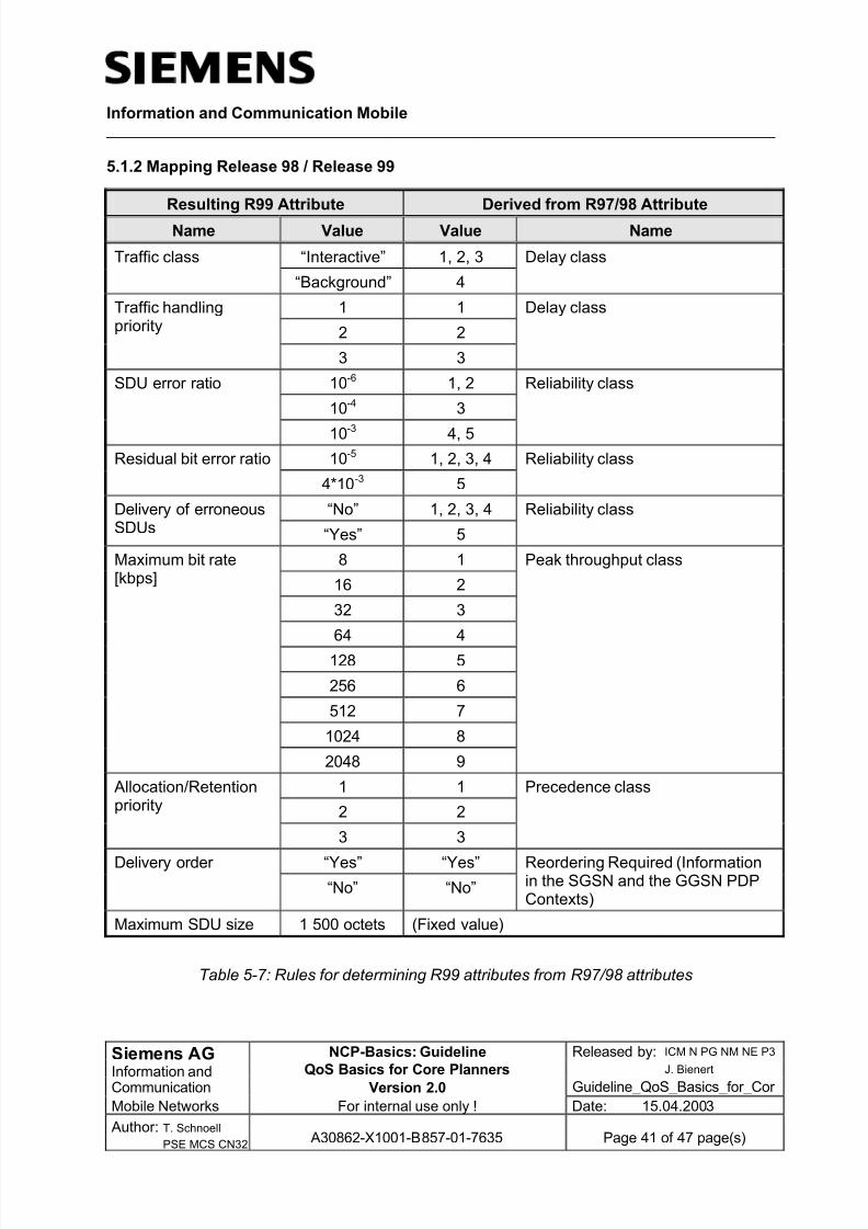
8/8/2019 QoS-Basics for Planners
http://slidepdf.com/reader/full/qos-basics-for-planners 41/47
Information and Communication Mobile ____________________________________________________________________________________
Siemens AG NCP-Basics: Guideline Released by: ICM N PG NM NE P3
Information and QoS Basics for Core PlannersJ. Bienert
Communication Version 2.0 Guideline_QoS_Basics_for_Cor
Mobile Networks For internal use only ! Date: 15.04.2003
Author: T. Schnoell
PSE MCS CN32 A30862-X1001-B857-01-7635 Page 41 of 47 page(s)
5.1.2 Mapping Release 98 / Release 99
Resulting R99 Attribute Derived from R97/98 Attribute
Name Value Value Name
“Interactive” 1, 2, 3Traffic class
“Background” 4
Delay class
1 1
2 2
Traffic handlingpriority
3 3
Delay class
10-6 1, 2
10-4 3
SDU error ratio
10-3 4, 5
Reliability class
10-5 1, 2, 3, 4Residual bit error ratio
4*10-3 5
Reliability class
“No” 1, 2, 3, 4Delivery of erroneousSDUs “Yes” 5
Reliability class
8 1
16 2
32 3
64 4
128 5
256 6
512 7
1024 8
Maximum bit rate[kbps]
2048 9
Peak throughput class
1 1
2 2
Allocation/Retentionpriority
3 3
Precedence class
“Yes” “Yes”Delivery order
“No” “No”
Reordering Required (Informationin the SGSN and the GGSN PDPContexts)
Maximum SDU size 1 500 octets (Fixed value)
Table 5-7: Rules for determining R99 attributes from R97/98 attributes

8/8/2019 QoS-Basics for Planners
http://slidepdf.com/reader/full/qos-basics-for-planners 42/47

8/8/2019 QoS-Basics for Planners
http://slidepdf.com/reader/full/qos-basics-for-planners 43/47
Information and Communication Mobile ____________________________________________________________________________________
Siemens AG NCP-Basics: Guideline Released by: ICM N PG NM NE P3
Information and QoS Basics for Core PlannersJ. Bienert
Communication Version 2.0 Guideline_QoS_Basics_for_Cor
Mobile Networks For internal use only ! Date: 15.04.2003
Author: T. Schnoell
PSE MCS CN32 A30862-X1001-B857-01-7635 Page 43 of 47 page(s)
5.2 Application classification
Below examples for applications mapped to traffic classes can be found.
Subscriber BaseService Traffic Class
Multi-media Services
Video streaming Streaming
Picture transmission Streaming / Interactive
Video telephony Conversational
Video conference Conversational
Music on demand Streaming / Interactive
E-postcard Background
Information Services
Search engines Interactive
Online translation Interactive
Booking and reservation news Interactive
E-mail Background
Push and pull services (stock price) Interactive
Financial information analysis Interactive
E-Commerce
Online Bank transaction InteractiveMicropayments Interactive
Online stock trading Interactive
Online shopping Interactive
Download ringing tones Interactive / Background
Online Auction Interactive
Online ticketing Interactive
Advertising Interactive / Background
Telematic
Fleet Management Interactive
Location based tracking Streaming / InteractiveInformation on traffic conditions Interactive / Background
Remote surveillance Streaming / Interactive
Dispatcher service Interactive / Background
Security
Camera surveillance of rooms Streaming / Interactive
Stolen vehicle tracking Streaming / Interactive
Detection of burglary Streaming / Interactive

8/8/2019 QoS-Basics for Planners
http://slidepdf.com/reader/full/qos-basics-for-planners 44/47
Information and Communication Mobile ____________________________________________________________________________________
Siemens AG NCP-Basics: Guideline Released by: ICM N PG NM NE P3
Information and QoS Basics for Core PlannersJ. Bienert
Communication Version 2.0 Guideline_QoS_Basics_for_Cor
Mobile Networks For internal use only ! Date: 15.04.2003
Author: T. Schnoell
PSE MCS CN32 A30862-X1001-B857-01-7635 Page 44 of 47 page(s)
Emergency alarm notification for ill or agepeople
Background (High priority)
Household device control Interactive
Public Information
Elections/voting Interactive / Background
Yellow Pages Interactive
Help and guidance Interactive
Property information Interactive
Leisure
Horse racing betting Interactive
Mark Six Interactive
Jokes Interactive
Chatroom Interactive
Interactive game Conversational / Interactive / Streaming
Intra/Internet
Access to Internet Interactive / Background
Access to Intranet Interactive / Background
Access to Extranet Interactive / Background
Mobile Office
Scheduler Background
Corporate email Background
Online Fax Background
Organizer access Interactive
Telephone book Interactive
Unified Messaging Background
Secretarial Service Interactive / Background
Location depending services
Restaurant finder Interactive
Tourist information Interactive
Mobile map/route guidance Interactive
EducationVirtual School Interactive
Online library Interactive
Online publications review Interactive
Remote consultation Interactive
Table 5-9: Mapping of applications to Traffic Class

8/8/2019 QoS-Basics for Planners
http://slidepdf.com/reader/full/qos-basics-for-planners 45/47
Information and Communication Mobile ____________________________________________________________________________________
Siemens AG NCP-Basics: Guideline Released by: ICM N PG NM NE P3
Information and QoS Basics for Core PlannersJ. Bienert
Communication Version 2.0 Guideline_QoS_Basics_for_Cor
Mobile Networks For internal use only ! Date: 15.04.2003
Author: T. Schnoell
PSE MCS CN32 A30862-X1001-B857-01-7635 Page 45 of 47 page(s)
5.3 Token Bucket Model
This chapter gives a rough overview about the Token Bucket Model, which is a mechanism that
can be use for policing or measurement tasks.
In the Token Bucket Model for a specific amount of data that have to be sent a specific amountof tokens (credits) are required.
The tokens (credits) are generated at the Token Bucket Rate [r] and stored in an imaginarybucket. The bucket can be filled with up to a specific size, the Token Bucket Size [b].
In the case of a full bucket the additional generated Token (Credits) are no longer stored in thebucket but are dropped.
Data buffer
Regulator
Token
Bucket
Rate
[r]
Token
Bucket
Rate
[r]
Token
Bucket
Size
[b]
Token
Bucket
Size
[b]
IP packet
min. pol. unit [m]min. pol. unit [m]
max. pack. size [M]max. pack. size [M]
Figure 5-1: Token Bucket Model
In the data transmission in the token bucket model three scenarios can occur:
• Full bucketIf the bucket is full, for the sending of a packet a specific amount of tokens have to beremoved from the bucket.
• Empty bucketIf the bucket is empty the packet which has to be sent is buffered until the requiredamount of Tokens are within the bucket.
• Partly filled bucketIf the bucket is partly filled either enough tokens for sending the packet are available or the packet has to be buffered until the bucket is filled with enough tokens again.

8/8/2019 QoS-Basics for Planners
http://slidepdf.com/reader/full/qos-basics-for-planners 46/47
Information and Communication Mobile ____________________________________________________________________________________
Siemens AG NCP-Basics: Guideline Released by: ICM N PG NM NE P3
Information and QoS Basics for Core PlannersJ. Bienert
Communication Version 2.0 Guideline_QoS_Basics_for_Cor
Mobile Networks For internal use only ! Date: 15.04.2003
Author: T. Schnoell
PSE MCS CN32 A30862-X1001-B857-01-7635 Page 46 of 47 page(s)
The Token Bucket Model is based on the following 5 parameters:
• Peak Data Rate [p]The Peak Data Rate defines the maximum rate at which packets can be sent in shortinterval time. The Peak Data Rate is measured in bytes/seconds
• Token Bucket Rate [r]The token bucket rate is the rate at which token in the sense of the token bucket modelare created. For processing a defined amount of data, a defined number of token arenecessary. The Bucket Rate is measured in bytes/seconds
• Token Bucket Size [b]The token bucket size describes the amount of tokens a bucket in the token bucket modelis able to hold. The Token Bucket Size is measured in bytes.
• Minimum Policed Unit [m]The Minimum Policed Unit is the size of the smallest packet to be treated. This includesthe application data and all protocol headers at or above IP Level. The Minimum PolicedUnit is measured in bytes.
• Maximum Packet Size [M]The Maximum Packet Size should be set to the size of the largest packet that might occur in the network. The Maximum Packet Size is measured in bytes.

8/8/2019 QoS-Basics for Planners
http://slidepdf.com/reader/full/qos-basics-for-planners 47/47
Information and Communication Mobile ____________________________________________________________________________________
5.4 Delay and Jitter
Specific for Real Time applications, which would be applications that use the UTMS QoS TrafficClass Streaming or Conversational have very strong requirements on delay and jitter since theyhave directly influence to the service.
The transfer delay is the time that a packets needs to be transferred through the network. Jitter is the additional time the packets deviates from the delay time.
The Figure 5-2 gives examples for delay and jitter. As can be seen the packet “IP 1” is injectedat the ingress of the network at a current time and received at the egress with a specific delay.
For the packet “IP 2” the same delay as for packet “IP 1” is expected. But the packet “IP 2” isreceived at the egress with an additional delay; this additional delay is the jttter.
For the definition of delay different approaches are possible. One the one hand the definition of delay the can be based on the transfer delay of the first sent packet. Since also the first sentpacket can receive a jitter the delay can also be based on an average value of sent packets.
t = 0
t = x
Ingress Egress
IP 1
IP 3
IP 3
IP 2
IP 2
IP 1
Jitter
Delay
Delay
Delay
Figure 5-2: Delay and Jitter