qualification and change control
DESCRIPTION
Qualification and Change Control pharmaceuticalTRANSCRIPT

9
Qualification and Change ControlSteven OstroveOstrove Associates, Inc., Elizabeth, New Jersey, U.S.A.
INTRODUCTION
The terms Qualification and Validation are often usedalmost interchangeably when dealing with meeting theGMPs. According to the definitions found on the ISPEweb pagea:& Qualification: Action of proving and documenting that
equipment or ancillary systems are properly installed,work correctly, and actually lead to the expected results.Qualification is part of validation, but the individualqualification steps alone do not constitute process vali-dation
& Validation: Establishing documented evidence whichprovides a high degree of assurance that a specific processwill consistently produce a product meeting its pre-determined specifications and quality attributes.Obviously, they are similar but not the same. The
intention of both is the same; the process (validation) andthe equipment (qualification) must be reproducible, meetpredetermined attributes and be well documented as totheir state and conditions. In short, equipment or equip-ment systems are Qualified and processes are Validated.There is a further subdivision to the distinction betweenQualification and Validation. Current trends in theindustry further divide the Qualification into the IQ andOQ protocols while the PQ usually belongs to Validation.These documents, in particular the IQ and OQ, will bediscussed in more detail later in this chapter.
According to the definition, Qualification is thatprocess whereby both the physical and operating charac-teristics of the equipment are documented. This meansthat the important or critical components are tested todocument and “prove” that they are:& What was ordered& Received as ordered (specified)& What was required for the process and& Operate as specified (for the specific process or use)
All of the equipment used in the production ofa pharmaceutical product must be qualified beforeit can be used in production. This includes not only theprocess equipment but also the process test instrumentsand supporting utilities. There are three main qualifica-tion documents or protocolsb used in the industry. Theyare the IQ, OQ, and PQ. This chapter will concentrate onthe IQ and OQ documents and some comments willbe made about the PQ. These three documents may becombined or kept as single entities depending on thecorporate philosophy and the complexity of the equip-ment or system being qualified. The first two (IQ and OQ)are considered qualification and the PQ is grouped intovalidation. If they are combined, then the IQ and OQ canbe called or considered an EQ. Recently, a fourth docu-ment, DQ, has come into use. This last document began inEurope and is now being used in the United States forboth medical devices and pharmaceuticals.
The purpose of any qualification protocol isto document the original installation conditions andestablish that the equipment is suitable for the taskit is assigned. The protocols need to be organized, easyto follow and must “test” each major component oroperation.
Testing during the IQ and OQ stage is performedeither on systems or on individual pieces of equipment.In general, it is best to use the system approach to thequalification program. Systems are established by com-bining individual units that must work together asone. An example of this is a refrigerator (e.g., condenser,cooling coil, fan, chamber) or a reactor system (e.g.,reactor, feed tank, receiving tank, pumps). Testingduring the PQ usually takes a working group or theentire process line (e.g., a packaging line) and demon-strates that it functions as expected as a unit.
Why do we need to qualify all of the manufacturingand associated equipment? Usually it is said that it isrequired by the FDA and/or the other regulatory agenciesthroughout the world. However, this should not be thereason to do qualification. The real reason to perform thequalification is that it makes good business sense, that is, itwill save the company money and time. Yes, there is anupfront cost to the qualification program; but if executedcorrectly it will save more than that cost during the life ofthe equipment, will help assure that the equipment isfunctioning as required, and will be easier to track andthus fix problems (if theywere to occur) during operation.While this chapter will concentrate primarily on the FDA
a International Society for Pharmaceutical Engineering.Abbreviations used in this chapter: cGMP, current good manufacturingpractice; CFR, Code of Federal Regulations; DQ, design qualifica-tion; DS, design specification; EQ, equipment qualification; FAT,factory acceptance test; FDA, Food and Drug Administration; FRS,functional requirement specification; GMP, good manufacturingpractice; HVAC, heating, ventilation, and air-conditioning; IQ,installation qualification; ISPE, International Society for Pharma-ceutical Engineering; LL, like-for-like; OQ, operationalqualification; PLC, programmable logic controllers; PQ, per-formance qualification; PV, process validation; QU, quality unit;SAT, site acceptance test; SOP, standard operating procedure; TM,trace matrix; URS, user requirements specification; V, vendoractivity.
b Protocols: the formal design or plan of an experiment or researchactivity (from ISPE web page).

requirements, the European Union, Japan, etc. all havesimilar requirements.
The term “Qualification” appears twice in Title 21 ofthe CFRc :& 21 CFR 211.25—Personnel Qualifications& 21 CFR 211.34—Consultants
These two sections deal with the qualification ofthe personnel implementing the study. This does notmean that qualification does not apply to the facility orequipment used or to other sections in the CFR, but it isexpected and understood that the tasks necessary toassure the company, and the regulatory agencies, thatthe equipment will function as expected is suitable forits intended use and will not alter or adulterate theproduct in any way are properly executed.
The second part of any qualification program is theimplementation of Change Control. This program isinstituted so that a qualified system is maintained in aqualified state during its useful lifetime.
This chapter will discuss each of the qualificationdocuments and describes how a change control programcan be effectively implemented and maintained. Cost,while not a concern of the regulatory agencies, is certainlya concern for each manufacturing site. The ideasexpressed in this chapter should help minimize the costand time allocated to complete these necessary functions.The examples presented here are intended only asexamples and should not be used as “absolute” answersto your qualification programs. It is not meant to be all-inclusive, but to serve as a guide to the development of acost-effective, compliant cGMP qualification programthat will satisfy regulatory requirements. This chapterwill not discuss PQ (except to touch on its relationshipwith the IQ and OQ) or the PV.
WHAT GETS QUALIFIED
Anything that is used in, or for, the production of apharmaceutical product or medical device (i.e., anythingthat comes into contact with the product) should bequalified. However, there really are limits on this. Thismeans that equipment, or systems, actually used as part ofthe production process for the production or manufac-turing of a pharmaceutical or medical device productmust be qualified prior to its use. This includes supportingutilities as well as all process equipment. Examples ofsome items that usually do not require qualification arethe plant electrical system (excluding the emergencypower), water used in the wash rooms, and the scoopsand related items used for manually transferring materialto another vessel (e.g., in the weigh room).
UtilitiesAll process utilities that have direct product contact or adirect or indirect impact on the product quality or efficacyneed to be qualified. If there is no direct impact on theproduct, the utility may be commissioned only (referbelow and Chapter 2). Some examples of utilities thatoften have no direct impact on the product include theHVAC system (except in sterile area operations), electricalpower, boiler steam (if used for general heat in the facility
and not to heat a reactor), or non-process compressed air(i.e., for actuating non-process control valves). Again, thethought must always be focused on their impact onthe product.
Certainly these systems impact the overall pro-duction. Without them there would be no production.However, the key here is they do not directly affect theproduct quality. These systems may affect the operator’scomfort (e.g., HVAC) or the availability of “power tools”(e.g., electricity), but if they are absent, product safety,efficacy, or stability is not impacted.
EquipmentAs stated before, all process equipment or systems needto be qualified prior to their use in production, but whatabout equipment that has been transferred from anotherfacility or process. The answer again is “YES”; it mustbe either qualified or re-qualified as the case may be. Ifthe equipment was not used in a similar operation, orif the product was different from the current intendeduse, the equipment must be qualified for its new use. It isbest to qualify a piece of equipment over its full operatingrange and functionality. This will allow its use in a varietyof potential future operations, not just the one for which itis currently being qualified.
Support equipment such as pumps, agitators, andheat exchangers also need to be fully qualified. Theseunits are typically qualified along with and as part of themajor unit with which they are associated.
Laboratory EquipmentLaboratory equipment, with the exception of basicresearch laboratory equipment, must be qualified priorto its use. This equipment is used to determine the statusor release of the product (or intermediates) either to thenext process step or for release for commercial distri-bution. Although test equipment often stands alone, thereare some instruments that are “on-line.” The productpasses through these on-line instruments and theresults are available immediately. In other cases, theproduct samples are taken to a lab for analysis andthe results are available at a later time.
THE ORDER OF A QUALIFICATION PROGRAM
The following is just one approach to a qualificationprogram. There are several things that must be completedprior to beginning a qualification program. These itemsare usually considered as prequalification. During theprequalification phase of the project, the qualificationteam is established. The person leading the qualificationteam must be able to set priorities, interface effectivelywith the engineering and construction teams, andorganize the qualification program to meet its desiredgoals. The Team Leader must assign qualified personnelto collect, review, and organize all of the documents thatwill be needed for the program.
To have an effective, well-managed and cost-effec-tive qualification project, the leader should follow thegeneral order shown in Figure 1 and Table 1.
After collecting and organizing the documentsby system, the next important step is to develop thequalification schedule. Like all project schedules, thisc Code of Federal Regulations—Title 21 Parts 210 and 211.
130 II: SUPPORT AND UTILITY SYSTEMS

schedule is likely to change and thus should be keptup-to-date by the manager or a dedicated scheduler.
By the time you get to organize the qualificationproject, the vendor should have submitted the equipmentmanuals, the certified equipment drawings, and theirown EQ protocols. Today, as compared to a few years
ago, most vendors have a validation/qualificationpackage available which can certainly be used as astarting point in developing your own qualificationprotocols. The vendor protocols should not be used aspresented, or as the only qualification documents sinceyour use is unique, and the vendor documents aredesigned to “pass” the equipment in a general appli-cation. You should also use the same protocol format foreach of your qualification documents, which will not besimilar to those provided by the vendor.
Now that you have the qualification team, thereference documents organized by system and theproject schedule established, you are ready to beginwriting the qualification protocols.
Table 2 lists some key documents that should becollected, in steps 1 through 3 in Table 1, prior topreparing any qualification document. This is a “WishList” since not all of the documents will be eitheravailable or needed. If all are available, then littledifficulty will be encountered in the following steps.Certainly, in any given project, there may be otherdocuments that pertain to the specific equipment orsystem that need to be added to this list.
After the protocol is prepared and approved,execution plans need to be made. This involves notifyingthe affected areas that qualification will be performedover a range of dates. Obviously, if a new area is being
Project ID’d ConceptualDesign
PreliminaryDesign
Detail Design
Issue forConstruction
BasicConstruction
FinishingConstruction
EquipmentInstallation
EquipmentStart-Up
Comissioning IQ
OQPQProcessValidation
Operate Facility
GMPReview
GMPReview
GMPReview
ValidationDocument Prep
ValidationDocument Prep
GMPReview
GMPReview
ProtocolCycle
ValidationDocument Prep
ValidationDocument Prep
V
VV
VV V
Figure 1 General outline of a qualification project. Dark grey denotes the responsibility of the qualification team and light grey denotesengineering or plant functions.
Table 1 Steps in Qualification Program
Define the project
Determine what equipment or systems need to be qualified
Determine when the equipment must be qualified in relation to
other equipment and to the overall project
Select the team
Train or brief the team on the project/process requirements
Obtain the relevant documents from the client/users
Review for good manufacturing practice compliance
Questions need to be asked and addressed
Establish the project schedule
Set or obtain protocol formats, using existing protocols where
available
Begin document (protocol) preparation
Review prepared documents (protocols)
Submit for client review and comment
Edit and update as necessary
Execute the protocol
Draft the final report
Submit report to client for comment
Finalize reports and close the project
9: QUALIFICATION AND CHANGE CONTROL 131

renovated or built, this notification is not necessary sincenone of the equipment may be used for productionpurposes until qualification and validation are complete.Arrangements must be made with needed specialists, testequipment suppliers, and the operators to assure thatduring the qualification testing there will be no delaysdue to missing or unavailable materials, equipment,or skills.
The people performing the tests need to review theprotocols before execution starts. They are to check thatall required materials, personnel and test instruments areready and that they know how to perform or direct thetesting to be done. They must understand the principle ofthe test as well as its execution.
Now that the entire program has been organizedand the documents needed for the qualification are beingprepared or collected, the next phase of the prequalifica-tion can take place. These activities are the factoryacceptance and site acceptance testing followed by thecommissioning program.
FACTORY ACCEPTANCE TEST AND SITEACCEPTANCE TEST
FATs are critical tests that should be performed prior tothe vendor shipping the unit to the production site. TheFAT should be completed on all major equipment beforethey leave the vendors’ facility. Thus, systems that arefabricated on-site, e.g., HVAC ducting, or process pipingdo not receive a FAT despite the fact that they are part of alarge and important system. FATs are designed to demon-strate that the vendor has produced a unit that willoperate as expected when delivered to the productionarea. The vendor, the receiving company or a third partydesignated by the receiving company, may prepare thetest documentation for the FAT. As with all qualificationactivities, the test script should be prepared in advanceand be accepted by the receiving company. The testsperformed should cover all of the major functionsthroughout their full operating ranges. In all testings,the software or PLC code aspects of the functions willneed to be verified. This “code review” should be part ofthe vendor audit program and will not be discussedfurther in this chapter.
If documented correctly, and signed by trainedobservers, some of the data collected in the FAT may beused to support the IQ or OQ protocols. Caution isneeded here in that QA and others must agree whichtest results may be used, and to what extent, since the FATmay not be considered a GMP-controlled document (ifnot approved or reviewed by QA), although the qualifica-tion protocols are controlled.
Examples of testing that may be performed as partof the FAT are the following:& Temperature control
& Ramp up/down& Hold or dwell times
& Speed control& Stability or lack of vibration during max run con-
ditions& Pressure hold or leak tests& Function of interlocks and other safety items.
Table 2 Document Wish List
Drawings
Process flow diagram
Piping and instrumentation diagram
Vendor equipment drawings
Electrical drawings
Piping isometric drawings
Equipment layouts
Airflow diagrams
Personnel flow diagrams
Material flow diagrams for
Raw materials
Wastes
In process
Finished products
Manuals
Operation
Cleaning
Preventive maintenance
Standard operating procedures (Note: Controlled drafts are acceptable
for the purposes of qualification efforts)
Operating
Process equipment
System controls
Preventive maintenance
Cleaning
Emergency shutdown
Area emergency procedures (e.g., fire, flood)
Backup for computer system data
Change control
Training
Calibration
Reports
Weld
Cleaning (prior to first use)
Balance (air/heating, ventilation, and air-conditioning)
Vendor tests—factory acceptance test (site acceptance test)
Passivation
Instrument loop checks
Specifications
Preliminary design specification
Operating ranges
User requirements specifications
Functional requirement specifications
Detailed design specification
Other
Purchase orders
Standards used (traceability)
Ladder logic (where appropriate)
Source code (where appropriate)
Batch records (where appropriate)
List of critical/non-critical
Instruments
Components
Spare parts
Catalog cut sheets
Traceability matrix (cross-reference all documents so that all items
are accounted for in the qualification)
Instruments
Contractor certifications
Personnel qualifications
Equipment certifications
Calibration certifications
Logs
Equipment use (History)
Cleaning
Preventative maintenance
132 II: SUPPORT AND UTILITY SYSTEMS
These are critical operations for the equipment (e.g.,blenders, granulators, reactors) and should be testedbefore the unit is shipped so that any errors may becorrected prior to installing and starting up the unit atthe production area. Successful completion of the FATwill save time in the end and gives the client theopportunity to make corrections to the specification orcorrect any miscommunication, or misinterpretation, ofthe user requirements.
After the equipment is installed and the contractoris ready to “turn” the unit over to the plant, the SAT isusually performed. This test may include the same testfunctions as the FAT, except that it is conducted at theclient’s site after the equipment or system is installed.It should be completed before the vendor leaves thesite and the final payment is made. The SAT mayinclude additional testing not performed at thevendor’s factory. These tests should demonstrate thatthe unit is installed and operating as expected withthe equipment owner’s utilities. This should not beconfused with the IQ or OQ testing, which is to beperformed later. The focus of the prequalificationtesting is to make the vendor demonstrate that allcomponents work properly so that commissioning andqualification can be started. One last point to keep inmind regarding the SAT is that with proper and completedocumentation (e.g., signing and dating observations)and agreement with QU, some of the data may be usedto support the IQ or OQ testing that will be performedlater in the qualification sequence.
COMMISSIONING (START-UP, SHAKEDOWN RUN)
Commissioning is the step used to “optimize” the equip-ment and set (or reset) for its function in the plant. Forexample, the control points, valves, and other functionalunits and are adjusted and “fixed” according to specifi-cations. Commissioning is a written set of proceduresused to prepare the equipment for qualification. Commis-sioning documents are not usually considered a cGMPdocument (i.e., approved by QU). Commissioningusually follows the SAT; however, it may be combinedwith the SAT. Some companies perform the commis-sioning after the IQ, while others do it before the IQ.The reason for the differences is the company’s philos-ophy on the commissioning document. The IQ is a GMPdocument and thus its control, data entry and all otheraspects must be carefully monitored. The changesperformed during commissioning usually do not lendthemselves to such control. Thus, it is often performedprior to the execution of the IQ.
All critical components of the system are to betested to ensure that the equipment will meet its expectedoperating criteria. Electrical or mechanical adjustmentsmay be necessary in order to reach design operatingcondition (e.g., air pressures may be adjusted, valvesreplaced, or wiring fixed), and these adjustments orchanges must be recorded to provide an accurate recordof the starting set points or operating conditions. Theadjustments provide assurance that the system willmeet the IQ or OQ requirements. Following the com-pletion of the SAT and commissioning steps, the unit canbe considered ready for qualification. This is why
Commissioning is considered a start-up operation andnot a cGMP-regulated function.
PROTOCOL CYCLE
As will be discussed in the rest of this chapter, thequalification protocols have a distinct pattern for theirgeneration and execution. The chart in Figure 2 gives onesuch cycle and the relative time usually required for eachstep. Note that the colors are coordinated to indicate theresponsible person or group for the activity. The timesindicated are approximate and will vary from projectto project.
APPROVALS
All qualification documents need to have two sets ofsignatures. The first preapproval set of signatures verifiesthat the information in the protocol is correct to the bestknowledge of those signing. The parties signing representthe various plant functions that have responsibility forthe units use or function. It is usual for all qualificationdocuments to be signed by at least the following:& Protocol author& Engineering& Operations/manufacturing& QU
Others groups may be needed (e.g., safety) toapprove the information in the protocol and their signa-tures may be added, according to the company’s policy,on qualification.
Each person reviewing and signing the preapprovalshould be reviewing the document from the perspectiveof his or her own specialty, that is, engineering reviews forcompliance to the engineering aspects, operations/manufacturing reviews it for its impact on the operatorsand the process (are all the buttons, controls, etc. thereand accounted for), and QA reviews it for adherence tocompany and regulatory requirements.
The second set of signatures, by the same disci-plines that signed the preapproval (above), is at thecompletion of the execution work. All testings arecomplete, all reports written and all deviations closed.Only when all of the protocol components are completewill the approvers again review the document and attestthat all data are correct to the best of their understanding(i.e., it appears correct, all completed and any correctionsare appropriate) and that the protocol is consideredcomplete and ready for the final report.
REPORTS
Summary reports must be prepared upon successfulexecution of the protocols. The reports may be combinedfor the IQ and OQ, or they may be independent. Theymay be attached to the protocols, or prepared as stand-alone documents, to be presented to the regulatoryagencies without the encumbrance of the supportingdata. Of course, either way, all supporting data andtests must be available upon request. The report mustalso be approved by the same people who approvedthe protocol.
9: QUALIFICATION AND CHANGE CONTROL 133

DETERMINING CRITICAL FACTORS/PARAMETERS
Qualification protocols need to test those parametersconsidered critical to their operation or function as wellas those functions necessary for their assigned function.Some of these may not be critical functions or controls but“secondary” gauges or controls that are used either tomake a cGMP decision in the process or to adjust theprocess flow. Thus, if a unit has 10 functions but onlyfive will ever be used, then only those five need to bequalified. However, all of the other unused functionsmust show that they do not interfere or compromise the
functions that are to be used. An important point here isthat unless or until the unused functions are qualified,the functions cannot be used in production. Criticalparameters, as well as the non-critical parameters, areusually determined during the protocol developmentstage but need to be reviewed and updated (others maybe added) when scaling up to production size.
A critical parameter or factor is usually defined as acharacteristic& that is necessary to produce the product& whose change will affect the product efficacy, safety,
or stability
Protocol ID’d Assign Author
CollectEquipment
InfoSet Up Eq.
FileSufficient Info
No
Yes
ProtocolAuthorEdit
ManagementReview
Acceptable
No
Stored
Yes
Submit to Client
Time 0 1 day1–5 days
3–6 days
1–10 days1–3 days1–3 days
0 days
Acceptable
No
PrepareProtocol
Client Review Submit forSignature
ExecuteProtocol
ReviewExecution Data
AcceptablePrepare
FinalReport
Yes
Yes
No
ManagementReview of
ReportAcceptable
Submit forSignature
Yes
No
1–10 days 1–5 days
2+ days1–3 days2–4 days
1–3 days 1–3 days
File as Complete
Submit to Client AcceptableClient Review
Yes
No
EstablishTests
1–5 days
ProtocolCompleted with
Signatures
0 days
Figure 2 Protocol life cycle.
134 II: SUPPORT AND UTILITY SYSTEMS
DOCUMENTS
Design QualificationThe DQ is an activity that has been in place for manyyears, but the documentation is relatively new. In itsoriginal form, it was known as the GMP review (Fig. 1).The DQ document is really a checklist for all parts of theengineering design. It breaks the entire design/build/validate project into sections and lists the expected docu-ments that are to be produced in each phase. Thefollowing is an example of a typical facility design andbuild project. The associated validationwork is also listed.
Project phases are as follows:& Conceptual design: GMP philosophy established& Preliminary design: Validation Master Plan started& Detailed design: qualification protocols prepared& Construction: on-site GMP inspection& Installation: execution of protocols& Qualification: completion of execution and final
reports prepared.The DQ reviews each section of the project and its
required documentation to provide an organized “check-list,” verifying that all critical aspects of the project aremet. For example, it will verify that all environmental andbuilding permits are in place and have been correctlyapplied, that the vendors have submitted their drawingsand specifications and the contractors are licensed,trained and sufficiently experienced in the area in whichthey are to work.
The DQ is equivalent to the design or GMP reviewthat has been ongoing for years. The DQ establishes anorder and methodology for reviewing the engineeringdrawings, assuring that all drawings are accounted forand have been appropriately reviewed.
In the past, the DQ has been performed as the“Equipment History File” or other similar names. Thepurpose again was to collect all relevant documents andmaterials for each system so that the protocol preparationand its execution will move smoothly. All components ofa system are listed and support material collected.
Equipment QualificationThe EQ is another term for the IQ and OQ respectivelycombined into one protocol. Each of these protocols isdiscussed in the following sections; however, keep inmind that they may be combined and presented as an EQ.
Installation QualificationPreparationThe IQ document specifies all of the physical attributes ofthe system or equipment requiring qualification. Thismeans that all physical parameters that may affect themachine operation, product safety, density, strength, orpurity need to be listed and verified as being appropriatefor its intended use. The IQ provides a record of theequipment ordered and verifies that it was correctlyreceived. It also provides a baseline record of the startingpoint and serves as a reference if another unit must beordered to replace the current one.
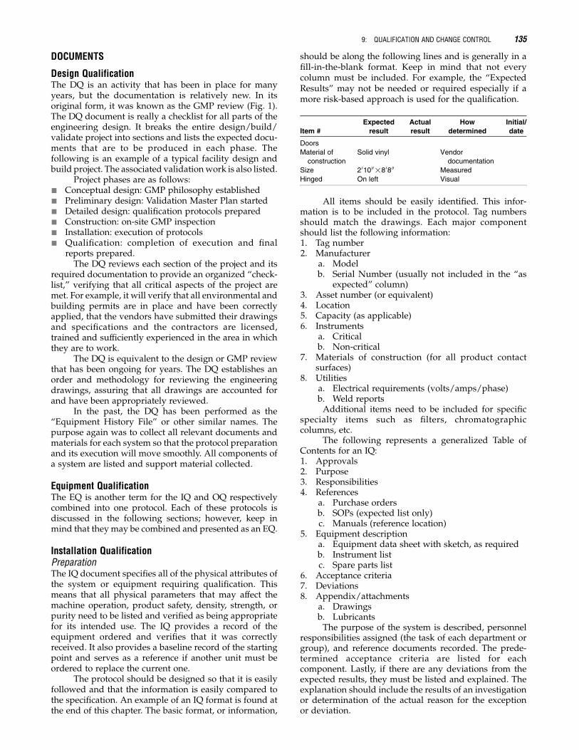
The protocol should be designed so that it is easilyfollowed and that the information is easily compared tothe specification. An example of an IQ format is found atthe end of this chapter. The basic format, or information,
should be along the following lines and is generally in afill-in-the-blank format. Keep in mind that not everycolumn must be included. For example, the “ExpectedResults” may not be needed or required especially if amore risk-based approach is used for the qualification.
Item #
Expected
result
Actual
result
How
determined
Initial/
date
Doors
Material of
construction
Solid vinyl Vendor
documentation
Size 2 01000!8 08 00 Measured
Hinged On left Visual
All items should be easily identified. This infor-mation is to be included in the protocol. Tag numbersshould match the drawings. Each major componentshould list the following information:1. Tag number2. Manufacturer
a. Modelb. Serial Number (usually not included in the “as
expected” column)3. Asset number (or equivalent)4. Location5. Capacity (as applicable)6. Instruments
a. Criticalb. Non-critical
7. Materials of construction (for all product contactsurfaces)
8. Utilitiesa. Electrical requirements (volts/amps/phase)b. Weld reportsAdditional items need to be included for specific
specialty items such as filters, chromatographiccolumns, etc.
The following represents a generalized Table ofContents for an IQ:1. Approvals2. Purpose3. Responsibilities4. References
a. Purchase ordersb. SOPs (expected list only)c. Manuals (reference location)
5. Equipment descriptiona. Equipment data sheet with sketch, as requiredb. Instrument listc. Spare parts list
6. Acceptance criteria7. Deviations8. Appendix/attachments
a. Drawingsb. LubricantsThe purpose of the system is described, personnel
responsibilities assigned (the task of each department orgroup), and reference documents recorded. The prede-termined acceptance criteria are listed for eachcomponent. Lastly, if there are any deviations from theexpected results, they must be listed and explained. Theexplanation should include the results of an investigationor determination of the actual reason for the exceptionor deviation.
9: QUALIFICATION AND CHANGE CONTROL 135

There are two major types of deviations or excep-tions: (i) deficiencies, i.e., not meeting the expected resultor condition, but not impacting or adversely affectingthe unit’s use as defined and (ii) deviation, i.e., a failureof the unit to meet its acceptance criteria that may affectits use as defined. These are usually just grouped intothe term “deviation” for sake of clarity in the protocol.However, a deficiency is more serious since it may affectthe process due to a “fault” in the design or constructionof the equipment. For example, if the acceptance criteriais “unit is red” and the color is blue, this is a deficiencywhile a deviation would be having two switches or tankswhen the design calls for three.
ExecutionDepending upon the order of the qualification work(commissioning and IQ), the IQ execution may bestarted at the time the equipment is being installed.However, this is usually not practical because thevendor or installers do not have the time, ability, knowl-edge or even the desire to do more paperwork at the timewhen they are trying to put a piece of equipment intoplace and to transfer ownership to the operatingcompany in order to get their final payment. This laststatement is not meant as a criticism of vendors, but as apoint where improvement can be made in the qualifica-tion process.
During the execution phase, the actual installation(as built/installed) is recorded. It is necessary to docu-ment that the unit was installed according to themanufacturer’s specifications (level, airflow require-ments verified, utilities correctly attached and more).In addition to the manufacturer’s requirements, theengineering department will often have its own specifi-cations. These should be found in the DSs and/or thefunctional specifications developed during earlier phasesof the project.
Execution of the IQ will involve the vendors,engineering and validation departments and third partycontractors (depending on the project size). In addition,some specialists may be needed, such as electriciansor plumbers, so that the measurements may be safelyconducted.
Operation QualificationPreparationThe OQ is the document that tests all of the operatingcharacteristics of the equipment. It verifies that all par-ameters demonstrating that the equipment operates overits entire range, as specified by the manufacturer, arecorrectly installed. Testing must be established in a logicalsequence so that the data, test equipment and staff can beutilized to their optimum efficiency. Thus, testing may notnecessarily be conducted in a “production” order, but in asequence that allows the unit to be tested and test resultsdocumented in the most efficient manner.
The unit should be tested over its entire operatingrange, not just the range to be used during production.The reason for this is simple: facilities never knowwhat product or conditions will be required in thefuture. It is very costly to stop production to testadditional speeds, etc. The primary use of the OQ issimilar to that of the IQ and serves as the basis for the
future. It sets a boundary for the operation of theequipment and serves as a benchmark for the status ofa unit’s operating parameters.
The tests that are to be conducted should includethose operations and functions listed in the user require-ments. These should be referenced against the functionalspecifications as well as vendor requirements. In no caseshould a test be required or performed that may damagethe equipment (e.g., run a pump dry).
Parameters include:& Speed
& Range& Speed control& Ramp up/down
& Temperatures& Ramp up/down& Operating range
& Flows& Maximum and minimumWater, or placebomaterials, not product, are usually
used in the OQ testing. However, in some cases wherea critical parameter must be met, such as mixing athigh viscosities, it may be necessary to use the productor a placebo with similar viscosity to mimic thespecific conditions.
The protocols should be written so that each test can“stand alone” and is easy to execute. An example of anOQ format is shown at the end of this chapter. It shouldspell out the procedure for testing and list the necessarytest instruments, for example:
Test instruments:& Tachometer
Test procedure:1. Start the motor according to SOP #XYZ12. Allow the motor to run for 30 seconds to 1 minute3. Measure revolutions per minute and record on table
X of this section.The following lists a typical Table of Contents for an
OQ protocol. As usual, additions will need to be made toassure that the tests fit the equipment to be qualified.& Approvals& Purpose& Responsibilities& Reference documents& Equipment description& Individual tests with test procedures& Test equipment needed& Acceptance criteria& Results& Deviations
As in the IQ, the system is described, responsibil-ities are assigned and the specific tests are delineated.Each test needs a stated purpose, the method to be usedin the testing, a list of test instruments, and a place torecord the results. The results page, or section, will thenbe used to prepare the final report as discussed above.In addition, each test should have its own predeterminedset of acceptance criteria that must be met in order to besuccessful. Lastly, if there are any deviations from theexpected results, then they must be investigated andexplained. The explanation should include the resultsof the investigation or determination as the actualreason or root cause for the deviation.
136 II: SUPPORT AND UTILITY SYSTEMS

ExecutionExecution of the OQ should be started only after thecompletion of the IQ execution. While this statementis the generally accepted approach, there are alwaysother possibilities; for example, if the qualification isperformed as an EQ, this would not be necessarysince both would be included in the same protocol. Inaddition, there are times when it may be necessary tostart the OQ prior to final IQ signoff. QA must approvethese exceptions which cannot, in any case, be startedwithout their involvement. For instance, it may bepossible to start the execution of the OQ if the missingitem does not affect the test or operation of the equip-ment (e.g., the test is for temperature control and themissing part is a mixing blade). Another example of thismay be that the “as-built” drawings have not beencompleted but have been marked up (red-lined) andsigned as correct. In both cases, these do not impact theoperation of the system or the specific test tobe conducted.
In the execution of the OQ, the relevant SOPs needto be in place at least in draft form and the operators whowill operate the equipment during the testing should befully trained and competent on the equipment they are tooperate, with training verification in the operator’s file.Engineering may be part of this testing, but it often falls tothe validation group or contractor. Another point to beaware of is that the OQ test sequences may not followactual operation but, again, will be designed to allow thebest use of staff and equipment.
Performance QualificationNote: This is often considered postqualification andbecomes a part of the validation teams’ efforts.
PreparationThe PQ is performed on those critical units or systemsthat usually function as a group and not individually.However, some single units may also be PQ testeddepending on their impact on the product. Examples ofthese are water systems (utilities), packaging lines (pro-duction), or autoclaves/steam sterilizers (production).Now that each major component has been qualified inthe IQ and OQ stage, the complete system must be run asexpected. The format for a PQ protocol is similar to an OQprotocol and is as follows:& Approvals& Purpose& Responsibilities& References& Process description& Test for process parameters& Acceptance criteria& Results& Deviations
In the PQ, the system is run using typical operatingparameters. In addition, “worst-case” testing is alsoperformed. Worst-case testing is not destructive to theequipment; it is only meant to be those conditions that arethe worst the process or materials can encounter duringnormal operation. These tests are considered limit testsor boundary testing. A major difference between OQ andPQ testing is that often the PQ tests are repeated and/or
run for extended periods to demonstrate reproducibilityor ability to operate over an extended period of time.PQ tests can be performed with production materialsrather than placeboes and the effect is directly measuredon the materials processed in the equipment.
ExecutionThe execution of the PQ protocols is again similar tothat of the OQ. Trained operators are needed to run theequipment, and sufficient test materials are needed forthe testing. It is best to run the tests starting with thelowest concentration or speed and build up to maximumoperation. This allows for conservation of materials. Also,it may minimize cleaning or set-up times between runs.All data must be carefully reviewed by the appropriateindividuals and a final report prepared. This report canbe incorporated into the IQ and OQ report or may standalone to represent the final acceptance of the unit(s).
CHANGE CONTROL
Change control is used to maintain the qualified, GMP or“validated” state of the equipment. Validation or qualifi-cation is an ongoing process that does not stop uponcompletion of the final qualification or validation report.Any change that is made to the equipment or its docu-mentation after it is qualified must be done under aformal change control program.
A change control program should be in place beforethe qualification starts. It becomes active upon com-pletion of the commissioning of the equipment sinceany change in the unit from that time will impact itsGMP readiness. Some companies start their changecontrol program upon the completion of the EQ activities.This, however, leaves open the possibility that a change,however small, may take place and not be properlyrecorded.
The purpose of change control is to have a writtenrecord of any and all changes that occur to the equipment,process or any of the supporting documentation,including computer software or PLC code. An outcomeof a working change control program is that all docu-ments related to the changed items are updated andreapproved if necessary. This includes the URS, FRS,DS, TM or other life cycle validation documents.
There are several categories of change control. Eachone has its own method for implementation. These cangenerally be grouped as:& Major—FDA should be notified immediately& Secondary major—reported to the FDA in the
annual report& Required—by a regulatory agency& Emergency& Local& Deferred
Let us take a brief look at each type.Major and secondary major changes are those
changes that may occur due to a change in the equipmentor use of a piece of equipment. This may be the result ofan emergency change or may be due to replacing agedequipment. An example of a major change would be thereplacement of a “ribbon blender” with a “V blender”
9: QUALIFICATION AND CHANGE CONTROL 137
even if the capacities are the same. Another examplewould be a change in the production step. An exampleof a secondary major change, i.e., one that can be reportedin the annual report, would be a change in the motor size.In any case, it is up to the QU and the regulatory affairsgroups to determine when and how the FDA should benotified of the change.
Required and emergency changes occur period-ically. Those changes mandated by any of the regulatoryagencies should be made as quickly as possible anddocumented as to what and how the change was made.Emergency changes occur at times when least expected.These changes can be minimized by following a completeand comprehensive preventative maintenance program.In an emergency, it is not usually necessary to prepareand file the document for change control at the time of theemergency. The emergency must be rectified first andthen the paperwork MUST be submitted. This allows theQA department to make a determination about the statusof the batch if one was involved. Most companies allow24 hours or the next business day from the emergency tofiling the papers.
The local type is by far the most common of allchanges, that is, any change that takes place in an SOP,or other GMP document related to the operation or useof manufacturing equipment, must be controlled anddocumented under the change control program. Thisincludes even minor corrections such as a spellingerror in an SOP. Other examples of local changes maybe renaming or renumbering the SOPs, replacing a labelon a piece of equipment or improvements related tosafety.
Deferred changes are minor changes to a systemthat might be identified and then placed on hold until amore convenient time for execution, or required change ismade and then implemented. This allows for theirinclusion in the change evaluation assessment.
A typical approach to change control is outlined asfollows:1. A change is thought to be necessary (e.g., a line
operator thinks that changing a manual valve to anyautomatic valve will not only make his/her job easierbut also makes the product more consistent as it willnot be dependent on an operator’s decision).
2. The operator writes up his idea and submits it tohis/her supervisor.
3. The supervisor decides whether it is a worthwhileidea and sends it to his/her supervisor or to theline manager.
4. The line manager reviews it and sends it to engin-eering.
5. Engineering reviews it and sends it to QA/regulat-ory/validation.
6. QA (regulatory and/or validation) approves andsends it to upper management.
7. Management reviews and finally approves.If the change request is approved, then the affected
departments will be notified. Usually this means engin-eering, validation (QA) and the requesting group.However, at any point in the review process, the idea
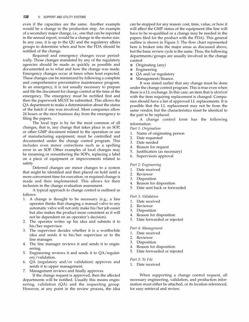
can be stopped for any reason: cost, time, value, or how itwill affect the GMP status of the equipment (the line willhave to be re-qualified or a change may be needed in thepapers filed for the product with the FDA). This generaloutline is shown in Figure 3. The flow chart representedhere is broken into the major areas as discussed above,but the basic review cycle is the same. Thus, the followingdepartments/groups are usually involved in the changecontrol:& Originating (any)& Engineering& QA and/or regulatory& Management/finance.
It was stated earlier that any change must be doneunder the change control program. This is true evenwhenthere is a LL exchange. In this case, an item that is identicalwith the item requiring replacement is changed. Compa-nies should have a list of approved LL replacements. It ispossible that the LL replacement may not be from thesame vendor, but the characteristics must be identical tothe part to be replaced.
A change control form has the followinginformation:Part 1: Origination
1. Name of originating person2. Date requested3. Date needed4. Reason for request5. Justification (as necessary)6. Supervisors approval
Part 2: Engineering
1. Date received2. Reviewer3. Disposition4. Reason for disposition5. Date sent back or forwarded
Part 3: Validation
1. Date received2. Reviewer3. Disposition4. Reason for disposition5. Date forwarded or rejected
Part 4: Management
1. Date received2. Reviewer3. Disposition4. Reason for disposition5. Date forwarded or rejected
Part 5: To File
1. Date received
When supporting a change control request, allnecessary engineering, validation, and production infor-mation must either be attached, or its location referenced,for easy retrieval and review.
138 II: SUPPORT AND UTILITY SYSTEMS

Need ID’d Assess Type ofChange
Assign Catagory
AFDA
Notified
BAnnualReport
CLocal - NonEmergency
Page 2Page 2
Notify Cat. ATeam
Prepare ChangeRequest
Submit forReview
ImplementChange
Submit forReview
Notify FDA(Obtain Approval)
Prepare ChangeRequest
Submit forReview
CompleteDocumentation
Regulatory Affairs
NeedIdentified
Emergency
NotifySupervisor
NotifySupervisor
Yes
NoPrepareChangeRequest
ImplementChange
PrepareChangeRequest
Route forApproval
ImplementChange
CompleteForms
CompleteForms Figure 3 General change control
flow plan.
9: QUALIFICATION AND CHANGE CONTROL 139
140 II: SUPPORT AND UTILITY SYSTEMS

CHANGE CONTROL DECISION
SECTION 5: Final Approval of Change (Resulting in Implementation)
Initiating Department:
Engineering Printed: Signature: Date:
Compliance: Printed: Signature: Date:
Validation Printed: Signature: Date:
QA: Printed: Signature: Date:
of
SECTION 6: Change Control Implementation Plan
Page
Installation Qualification
Instructions
ActualACTION STEPS
All Steps and IncludeDocumentation Updates
RequestorWho's
ResponsibleTarget
CompletionDate Begun Completed
Notes and/orAttachments
1. For each data sheet, record the requested information in ink. A “Y” or "Yes" answer is required for acceptance,and all “N” or "No"replies, and/or “N/A” replies, must be explained in the comments section.
2. When more than one unit of the same type exists, replicate the corresponding data sheets to matchand uniquely identify each.
3. When a list of acceptable options is presented, circle, underline or otherwise indicate the option that isactually present.
4. Initial and date each verification.
5. Sign and date at the end of each section. Record any unusual/additional information in the comments.Record any deviation and its explanation in the Comments area of each section.
6. Each Description and/or Verification box must be completed, signed and dated in the assigned spaceusing an ink pen.
Add additional page(s) if needed
9: QUALIFICATION AND CHANGE CONTROL 141
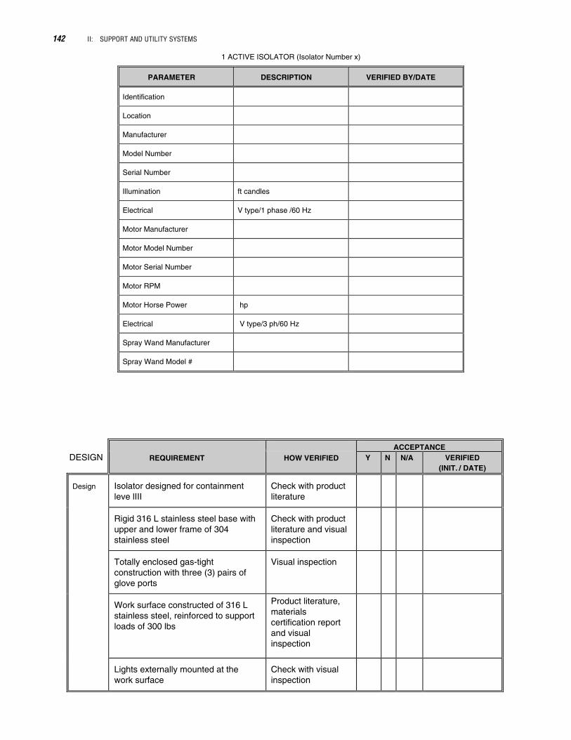
1 ACTIVE ISOLATOR (Isolator Number x)
PARAMETER DESCRIPTION VERIFIED BY/DATE
Identification
Location
Manufacturer
Model Number
Serial Number
Illumination ft candles
Electrical V type/1 phase /60 Hz
Motor Manufacturer
Motor Model Number
Motor Serial Number
Motor RPM
Motor Horse Power hp
Electrical V type/3 ph/60 Hz
Spray Wand Manufacturer
Spray Wand Model #
DESIGNACCEPTANCE
REQUIREMENT HOW VERIFIED Y N N/A
Design Isolator designed for containmentleve lIII
Check with productliterature
Rigid 316 L stainless steel base withupper and lower frame of 304stainless steel
Check with productliterature and visualinspection
Totally enclosed gas-tightconstruction with three (3) pairs ofglove ports
Visual inspection
Work surface constructed of 316 Lstainless steel, reinforced to supportloads of 300 lbs
Product literature,materialscertification reportand visualinspection
Lights externally mounted at thework surface
Check with visualinspection
VERIFIED(INIT. / DATE)
142 II: SUPPORT AND UTILITY SYSTEMS

ACCEPTANCE
REQUIREMENT HOW VERIFIEDY N N/A
DesignEasy replacement of parts such aslight bulbs, HEPA filter housings,blower motors, etc., with outbreaking containment
Check withproduct literatureand visualinspection
Glove ports and sleeves made of
Check withproduct literatureand visualinspection
Enclosures designed to maintain 100 fpmthrough a glove port in the event of failure
Check withproduct literatureand visualinspection
Spray wand providedCheck with visualinspection
Drainage connection with asanitary flush bottom valve andsanitary connection
Check withproduct literatureand visualinspection
Isolators designed for multipleoperators
Check with visualinspection
Framework will be round tubular and onlocking castors with height adjustable legs
Check with visualinspection
A minimum of four (4) sanitaryports in which electrical cords can pass
Check with visualinspection
VERIFIED(INIT. /DATE)
9: QUALIFICATION AND CHANGE CONTROL 143

MECHANICAL
ACCEPTANCE
REQUIREMENT HOW VERIFIED Y N N /A VERIFIED(INIT. /DATE)
Mechanical All foreign objects havebeen removed
Check withvisual inspection
Properly braced andsupported
Check withvisual inspection
Controls are properlyidentified
Check withvisual inspection
Bottom surface of theisolator is sloped in thedirection of the drain
Check withvisual inspection
Gauges, control valvesand/or pneumaticoperators installed
Check withvisual inspection
Verify that the unit canbe locked out/tagged out
Check withvisual inspection
ELECTRICAL
ACCEPTANCE
REQUIREMENT VERIFICATION Y N N/A VERIFIED(INIT. /DATE)
460 V type/3 ph/60 Hz Physical verificationwith certifiedequipment
Grounded
DOCUMENTATIONACCEPTANCE
REQUIREMENT VERIFICATION Y N N/A
GeneralDocumentation
Product literature is onfile in the SystemDescription located inEngineering
Check withvisualinspection
Product literaturecontains spare partslist
Check withvisualinspection
Product literaturecontains electricalschematics anddiagrams
Check withvisualinspection
SOPs OperationMaintenanceCleaning
Emergencies
VERIFIED(INIT. /DATE)
144 II: SUPPORT AND UTILITY SYSTEMS
BIBLIOGRAPHYBiotechnology Inspection Guide Reference Materials and
Training Aids, 1991.Code of Federal Regulations (21 CFR 210), 2006.Code of Federal Regulations (21 CFR 211), 2006.Commissioning and Qualification Baseline Guide ISPE, Volume
5, 2005.FDA Guide to the Inspection of Quality Systems, 1999.FDAGuideline on General Principles of Process Validation, May
1987.FDA Guideline documents (www.fda.gov/opacom/ more-
choices/industry/guidedc.htm).
Gibson W, Powell-Evens K. Validation Fundamentals—How to,What to, When to Validate. Interpharm/CRC–1998.
Good Drug Regulatory Practices, A Regulatory Affairs QualityManual Helene I. Dumitriu–Interpharm Press, Inc. 1998.
Nally, JD (ed). Good Manufacturing Practices for Pharma-ceutical 6th Ed. Informa Healthcare, 2007.
Quality Systems Approach to Pharmaceutical Current GoodManufacturing Practice Regulations, 2006.
www.emea.europa.eu/.www.picscheme.org/index.php.www.who.int/en/.
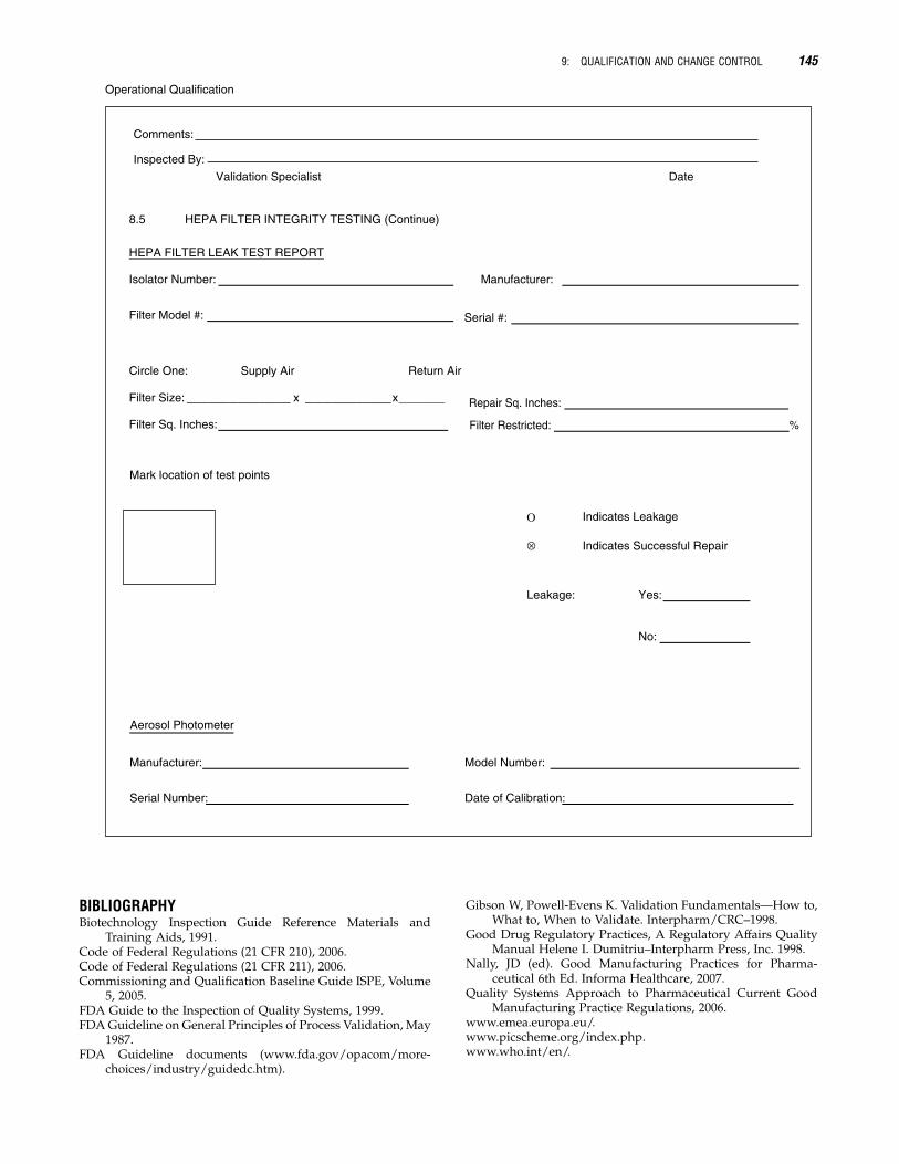
Operational Qualification
8.5 HEPA FILTER INTEGRITY TESTING (Continue)
HEPA FILTER LEAK TEST REPORT
Isolator Number: Manufacturer:
Filter Model #: Serial #:
Circle One: Supply Air Return Air
Filter Size: x x
Filter Sq. Inches:
Repair Sq. Inches:
Filter Restricted: %
Mark location of test points
Ο Indicates Leakage
⊗ Indicates Successful Repair
Leakage: Yes:
No:
Aerosol Photometer
Manufacturer: Model Number:
Serial Number: Date of Calibration:
Comments:
Inspected By:
Validation Specialist Date
9: QUALIFICATION AND CHANGE CONTROL 145
