qualitative temporal analysis: towards a full implementation of the fault tree handbook
TRANSCRIPT

ARTICLE IN PRESS
Control Engineering Practice 17 (2009) 1115–1125
Contents lists available at ScienceDirect
Control Engineering Practice
0967-06
doi:10.1
� Corr
E-m
y.i.papa
journal homepage: www.elsevier.com/locate/conengprac
Qualitative temporal analysis: Towards a full implementation of the FaultTree Handbook
Martin Walker �, Yiannis Papadopoulos
Department of Computer Science, University of Hull, UK
a r t i c l e i n f o
Article history:
Received 25 June 2007
Accepted 13 October 2008Available online 26 November 2008
Keywords:
Fault trees
Temporal logic
Safety critical
Safety analysis
Reliability
61/$ - see front matter & 2008 Elsevier Ltd. A
016/j.conengprac.2008.10.003
esponding author.
ail addresses: [email protected] (M. W
[email protected] (Y. Papadopoulos).
a b s t r a c t
The Fault Tree Handbook has become the de facto standard for fault tree analysis (FTA), defining the
notation and mathematical foundation of this widely used safety analysis technique. The Handbook
recognises that classical combinatorial fault trees employing only Boolean gates cannot capture the
potentially critical significance of the temporal ordering of failure events in a system. Although the
Handbook proposes two dynamic gates that could remedy this, a Priority-AND and an Exclusive-OR
gate, these gates were never accurately defined. This paper proposes extensions to the logical
foundation of fault trees that enable use of these dynamic gates in an extended and more powerful FTA.
The benefits of this approach are demonstrated on a generic triple-module standby redundant system
exhibiting dynamic behaviour.
& 2008 Elsevier Ltd. All rights reserved.
1. Introduction and background
Fault tree analysis (FTA) is a well-established system analysistechnique widely used in reliability engineering and systemsafety. It was created in the 1960s and since then has been usedin a variety of fields, including the automotive, aerospace, andnuclear industries, where numerous applications have beenreported on safety critical control systems. FTA is a deductiveanalysis method, meaning that the analysis starts with a systemfailure and works backwards to try to determine its root causes.The result is a fault tree, which represents this knowledgegraphically by showing the logical connections between differentfaults and their causes. The system failure is the top event of thefault tree, and it is connected to a set of basic events, or rootcauses, by a system of logical gates such as AND and OR andintermediate events. From the resultant fault tree, it is thenpossible to see how combinations of smaller basic faults, such asfailures of individual components or certain environmentalconditions, can cause major failures in the system as a whole.
The fault tree itself is then analysed to produce more usefulinformation about the failure behaviour of the system. Thisfurther analysis comes in two forms: qualitative (logical) analysisand quantitative (probabilistic) analysis. Qualitative analysis isperformed by reducing the fault tree to its minimal cut sets (MCSs),
ll rights reserved.
alker),
which are the smallest combinations of failures necessary to causethe top events; these MCSs are easier to understand than the faulttree as a whole. Quantitative analysis assigns probabilities to eachof the basic events based on failure and repair rates, and fromthese, the probability of the top event occurring can also beestimated. These processes are best described in the Fault Tree
Handbook (Vesely, Goldberg, Roberts, & Haasl, 1981), which setsout the fundamentals of fault trees and explains the principles offault tree construction and analysis.
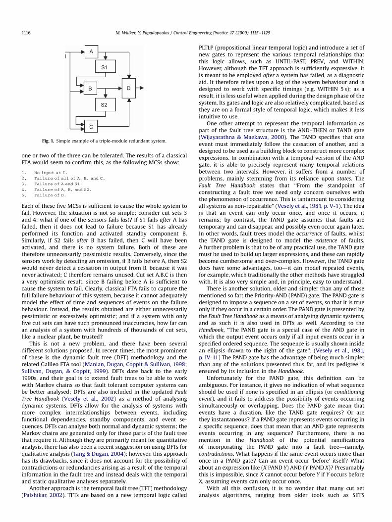
Unfortunately, there is a notable absence in FTA: it cannotexpress time- or sequence-dependent dynamic behaviour. Faulttrees rely upon classical Boolean logical gates to make connectionsbetween the basic events and the system failure, and these simplegates struggle to model the dynamic behaviour of systems in whichtime plays a major role. Such systems include those with differentmodes of operation, in which the failure behaviour changesdepending on which mode is in operation; systems with redundantor standby components, which can partly adapt to the presence offailures; and more generally, systems in which the failurebehaviour is dependent on the sequence of events. For example,consider the triple-module standby redundant system in Fig. 1.
The system is generic in the sense that component A, B, and Ccould be any input, control or actuating device. A is the primarycomponent that takes input from I, performs some function on it,and feeds the result to D. S1 is a monitoring sensor that detects anomission of output from A and activates the first standby, B.Similarly, S2 is another sensor that detects a failure of B andactives the second standby, C. In theory, all three components A, B,and C must fail in order for the whole system to fail—the failure of
ARTICLE IN PRESS
IA
S1
B D
S2
C
Fig. 1. Simple example of a triple-module redundant system.
M. Walker, Y. Papadopoulos / Control Engineering Practice 17 (2009) 1115–11251116
one or two of the three can be tolerated. The results of a classicalFTA would seem to confirm this, as the following MCSs show:
1.
No input at I.2.
Failure of all of A, B, and C.3.
Failure of A and S1.4.
Failure of A, B, and S2.5.
Failure of D.Each of these five MCSs is sufficient to cause the whole system tofail. However, the situation is not so simple; consider cut sets 3and 4: what if one of the sensors fails last? If S1 fails after A hasfailed, then it does not lead to failure because S1 has alreadyperformed its function and activated standby component B.Similarly, if S2 fails after B has failed, then C will have beenactivated, and there is no system failure. Both of these aretherefore unnecessarily pessimistic results. Conversely, since thesensors work by detecting an omission, if B fails before A, then S2would never detect a cessation in output from B, because it wasnever activated; C therefore remains unused. Cut set A.B.C is thena very optimistic result, since B failing before A is sufficient tocause the system to fail. Clearly, classical FTA fails to capture thefull failure behaviour of this system, because it cannot adequatelymodel the effect of time and sequences of events on the failurebehaviour. Instead, the results obtained are either unnecessarilypessimistic or excessively optimistic; and if a system with onlyfive cut sets can have such pronounced inaccuracies, how far canan analysis of a system with hundreds of thousands of cut sets,like a nuclear plant, be trusted?
This is not a new problem, and there have been severaldifferent solutions proposed. In recent times, the most prominentof these is the dynamic fault tree (DFT) methodology and therelated Galileo FTA tool (Manian, Dugan, Coppit & Sullivan, 1998;Sullivan, Dugan, & Coppit, 1999). DFTs date back to the early1990s, and their goal is to extend fault trees to be able to workwith Markov chains so that fault tolerant computer systems canbe better analysed; DFTs are also included in the updated Fault
Tree Handbook (Vesely et al., 2002) as a method of analysingdynamic systems. DFTs allow for the analysis of systems withmore complex interrelationships between events, includingfunctional dependencies, standby components, and event se-quences. DFTs can analyse both normal and dynamic systems; theMarkov chains are generated only for those parts of the fault treethat require it. Although they are primarily meant for quantitativeanalysis, there has also been a recent suggestion on using DFTs forqualitative analysis (Tang & Dugan, 2004); however, this approachhas its drawbacks, since it does not account for the possibility ofcontradictions or redundancies arising as a result of the temporalinformation in the fault tree and instead deals with the temporaland static qualitative analyses separately.
Another approach is the temporal fault tree (TFT) methodology(Palshikar, 2002). TFTs are based on a new temporal logic called
PLTLP (propositional linear temporal logic) and introduce a set ofnew gates to represent the various temporal relationships thatthis logic allows, such as UNTIL-PAST, PREV, and WITHIN.However, although the TFT approach is sufficiently expressive, itis meant to be employed after a system has failed, as a diagnosticaid. It therefore relies upon a log of the system behaviour and isdesigned to work with specific timings (e.g. WITHIN 5 s); as aresult, it is less useful when applied during the design phase of thesystem. Its gates and logic are also relatively complicated, based asthey are on a formal style of temporal logic, which makes it lessintuitive to use.
One other attempt to represent the temporal information aspart of the fault tree structure is the AND–THEN or TAND gate(Wijayarathna & Maekawa, 2000). The TAND specifies that oneevent must immediately follow the cessation of another, and isdesigned to be used as a building block to construct more complexexpressions. In combination with a temporal version of the ANDgate, it is able to precisely represent many temporal relationsbetween two intervals. However, it suffers from a number ofproblems, mainly stemming from its reliance upon states. TheFault Tree Handbook states that ‘‘From the standpoint ofconstructing a fault tree we need only concern ourselves withthe phenomenon of occurrence. This is tantamount to consideringall systems as non-repairable’’ (Vesely et al., 1981, p. V-1). The ideais that an event can only occur once, and once it occurs, itremains; by contrast, the TAND gate assumes that faults aretemporary and can disappear, and possibly even occur again later.In other words, fault trees model the occurrence of faults, whilstthe TAND gate is designed to model the existence of faults.A further problem is that to be of any practical use, the TAND gatemust be used to build up larger expressions, and these can rapidlybecome cumbersome and over-complex. However, the TAND gatedoes have some advantages, too—it can model repeated events,for example, which traditionally the other methods have struggledwith. It is also very simple and, in principle, easy to understand.
There is another solution, older and simpler than any of thosementioned so far: the Priority-AND (PAND) gate. The PAND gate isdesigned to impose a sequence on a set of events, so that it is trueonly if they occur in a certain order. The PAND gate is presented bythe Fault Tree Handbook as a means of analysing dynamic systems,and as such it is also used in DFTs as well. According to theHandbook, ‘‘The PAND gate is a special case of the AND gate inwhich the output event occurs only if all input events occur in aspecified ordered sequence. The sequence is usually shown insidean ellipsis drawn to the right of the gate’’. (Vesely et al., 1981,p. IV-11) The PAND gate has the advantage of being much simplerthan any of the solutions presented thus far, and its pedigree isensured by its inclusion in the Handbook.
Unfortunately for the PAND gate, this definition can beambiguous. For instance, it gives no indication of what sequenceshould be used if none is specified in an ellipsis (or conditioning
event), and it fails to address the possibility of events occurringsimultaneously or overlapping. Does the PAND gate mean thatevents have a duration, like the TAND gate requires? Or arethey instantaneous? If a PAND gate represents events occurring ina specific sequence, does that mean that an AND gate representsevents occurring in any sequence? Furthermore, there is nomention in the Handbook of the potential ramificationsof incorporating the PAND gate into a fault tree—namely,contradictions. What happens if the same event occurs more thanonce in a PAND gate? Can an event occur ‘before’ itself? Whatabout an expression like (X PAND Y) AND (Y PAND X)? Presumablythis is impossible, since X cannot occur before Y if Y occurs beforeX, assuming events can only occur once.
With all this confusion, it is no wonder that many cut setanalysis algorithms, ranging from older tools such as SETS
ARTICLE IN PRESS
M. Walker, Y. Papadopoulos / Control Engineering Practice 17 (2009) 1115–1125 1117
(Worrell & Stack, 1978) to some versions of more modern softwarepackages like Isograph’s FaultTree+, simply treat the PAND gate asa normal AND gate for the purposes of logical reduction. It is oftenargued that the replacement of a PAND by an AND simply leadsonly to a conservative prediction of the failure behaviour ofthe system, but this claim is not necessarily true, as alreadyexplained; as seen in Fig. 1, a failure of both A and S1 will onlycause a failure of the system if S1 does not fail after A has failed.Using an AND gate in this instance is not only pessimistic, it islogically incorrect and potentially misleading; in other cases, theresults can even be overly optimistic.
Despite this lack of clarity in terms of the qualitative analysisof PAND gates, there are techniques of analysing PAND gatesquantitatively. The quantification of sequential failures in a faulttree is known as sequential failure logic (SFL). It is often necessaryto use SFL to aid the quantitative analysis of dynamic systems andhas been applied to space satellites, human–robot systems,product liability prevention and more (Long, Sato, & Horigome,2000). There are at least two methods of quantifying SFL: Markovmodels, such as those used by DFTs, can be used; in addition, thePAQ (Priority-AND Quantification) method, originally proposed byFussel, Aber and Rahl (1976), can be used. There are advantagesand disadvantages to both; Markov chains are more complicated,but more accurate, whilst the PAQ method is applicable to a widerrange of systems, but is less precise. However, performingquantitative analysis in these cases without first performing atrue qualitative analysis can be problematic; a probabilisticanalysis of (X PAND Y) AND (Y PAND X) would not result in aprobability of 0, despite the fact that it is logically impossible. Thiscan result in an unnecessarily pessimistic reliability estimation.
Before the PAND can be properly used in FTA, it needs to bebetter defined so that it can be analysed qualitatively. That is thegoal of this paper. Section 2 describes the Pandora methodology,which is aimed at providing a more thorough definition for thePAND gate, allowing qualitative temporal analysis to take place.Section 3 covers the laws that make this analysis possible, and inSection 4, the qualitative analysis process itself is described.Section 5 demonstrates the advantages of the Pandora approachon the example system given above, and finally the conclusionsare presented in Section 6.
2. Introducing Pandora
Pandora1 is a new extension to FTA designed to enable faulttrees to model event sequences and relative temporal ordering,which it is hoped will aid in the analysis of dynamic systems(Walker & Papadopoulos, 2006). To that end, Pandora is builtaround a redefinition of the PAND gate. Many of the problemswith the PAND stem from its ambiguous definition in the Fault
Tree Handbook, which means it is difficult to use successfully inqualitative analysis. The definitions used in Pandora are intendedto remove these ambiguities and provide a framework for thequalitative analysis of both PAND gates and other ‘‘temporal’’gates, as will be described shortly.
2.1. Events
To address the problems with the Handbook’s definition of thePAND gate, it is important to start at the beginning, with theevents themselves. The Handbook does not define events withtime in mind; it says only that a basic event is ‘‘a basic initiatingfault event that requires no further development’’ (Vesely et al.,
1 PAND-ORA: hour or ‘‘time’’ (ORA ½ora� in Greek) of PAND gates.
1981, p. IV-2). However, it has already been stated that eventsrepresent occurrences of faults rather than the existence of faults,and the Handbook further states that ‘‘under conditions of norepair, a fault that occurs will continue to exist’’ (Vesely et al.,1981, p. V-1). Pandora takes these statements and defines faulttree events to be true at the first moment of occurrence of thatevent; any subsequent occurrences (i.e. after a fault has beenrepaired and it fails again) are ignored, since the event is alreadytrue. It is also assumed that events occur instantaneously.Therefore:
�
An event in Pandora represents the occurrence of a fault orexpected system process, or the transition of the system into acertain state. � If the fault/state transition has not yet occurred, the event isfalse.
� When the fault/transition occurs, the event becomes true andwill remain true thereafter.
� An event cannot go from being true to false, only from false totrue—thus systems are considered unrepairable for thepurposes of qualitative analysis. However, it is possible topartially model intermittent or repairable failures by repre-senting each instance of the failure as a separate event.
� An event is instantaneous—it goes instantly from being false tobeing true.
� To model the cessation of a fault or a state, a second eventmust be used.
This simplifies the situation and avoids the difficulties that plaguethe TAND gate; since events do not ‘‘un-occur’’ or cease, it is notpossible in Pandora for one event to occur immediately afteranother event ceases, and nor is it possible for them to partiallyoverlap. Although these assumptions may seem restrictive, it isusually possible to find ways to model more complex scenarios,e.g. by representing non-failure events (such as repair or othercessation of a failure) explicitly in the fault tree. Therefore unlikewith the TAND gate, which models a number of different temporalrelations between two event intervals, in Pandora there are onlythree possible temporal relations between two events X and Y, andonly one can be true at once:
�
Before—X occurs before Y. � Simultaneous—X occurs at the same time as Y. � After—X occurs after Y, or equivalently, Y occurs before X.Note that this is strictly a relative system of time: it is notnecessary to know the exact moment at which an event occurs aslong as it is possible to determine when an event occurred relativeto other events.
2.2. The conjunctive temporal gates
Pandora defines the PAND gate to represent the first of thesethree relations, the Before relation, so that X PAND Y means ‘‘Xoccurs before Y’’. The PAND gate can also represent the thirdrelation, After, by reversing its inputs; thus Y PAND X can alsomean ‘‘X occurs after Y’’. To represent the second temporalrelation, another gate is needed. The authors of the TAND gateredefine the normal logical AND gate to represent this situation,so that X AND Y means that X and Y both begin and end at thesame time (Wijayarathna, Kawat, Santosa & Isogai, 1997). Ratherthan change the meaning of a well-understood gate like the AND,Pandora introduces a new gate instead, the ‘Simultaneous-AND’(or SAND) gate. This gate represents the second temporal relationonly, so that it is true only if all of its inputs occur simultaneously;
ARTICLE IN PRESS
M. Walker, Y. Papadopoulos / Control Engineering Practice 17 (2009) 1115–11251118
the AND gate retains its usual meaning of being true if all of itsinputs occur, regardless of when. Thus, with both the PAND andSAND gate, all the temporal relations possible between two eventscan be represented in Pandora.
By using these two gates in this way, it is possible to avoid theambiguities of whether or not events can overlap or occursimultaneously in a PAND gate, which was one of the problemswith the original definition; it is not possible for a SAND gate anda PAND gate to both be true if they have the same inputs.Furthermore, the PAND gate is true only if its input events alloccur in order from left to right, i.e. its leftmost event must occurbefore its rightmost event. This also avoids the problem of whatordering to use if none is explicitly specified by a conditioningevent.
Note that the precise meaning of ‘‘simultaneous’’ can varyaccording to the nature of the system in question; the level ofgranularity is not fixed. Two events are treated as occurringsimultaneously as long as they occur together within a given timeperiod. The key assumption is that they occur in sufficientproximity that the transient effects of any precise ordering canbe ignored, whereas if they occurred further apart, these effectswould grow more noticeable. For example, if two failure eventseach take 1 s for their effects on a system to become apparent,then they could be treated as simultaneous as long as they bothoccur within a second of each other. In practice, the SAND isfrequently used to represent scenarios where a common cause ispresent, which can be assumed to trigger multiple failures at thesame (or approximately the same) time.
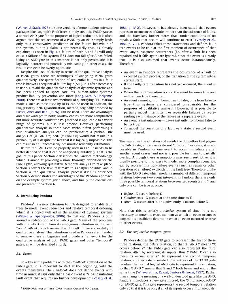
PAND gate SAND gate POR gate
Fig. 2. The symbology of the temporal gates.
2.3. The disjunctive temporal gate
However, both the PAND and SAND represent temporalconjunctions of events—what about disjunctions? The Fault Tree
Handbook also includes a strange illustration depicting anExclusive-OR (XOR) gate as being equivalent to an OR gate witha conditioning event attached specifying an order, i.e. A XOR B isequal to A OR B assuming A occurs before B (Vesely et al.,1981, p. IV-10). This conflicts with the traditional definition of theXOR gate, which states that only one input event must be true—adefinition which is also given in the Handbook on the same page.However, the traditional XOR gate implicitly uses NOT gates toachieve this, as A XOR B is traditionally equivalent to A.:B+:B.A(where +, . and : represent OR, AND, and NOT, respectively). TheHandbook does not include NOT gates, and using this definitionwould result in a more complex non-coherent fault tree, becausethe occurrence of A and then B would result in the XOR firstbecoming true and then becoming false again. This also conflictswith the definitions in Pandora, which states that an event (orgate) can only go from being false to being true. Therefore, theHandbook’s illustration avoids this by specifying a sequence, i.e. itallows both events to occur, as long as they occur in a certainorder. This definition is more like a ‘Priority-OR’ gate than thetraditional XOR gate.
Pandora takes this idea and creates a new gate, the Priority-ORor ‘‘POR’’ gate, to represent this sort of situation (Walker &Papadopoulos, 2007). The OR gate is true if at least one of its inputevents is true, and becomes true at that moment. The POR issimilar, but gives its first input priority (hence its name). For thePOR to be true, this leftmost input must also be true. Furthermore,this input must precede all of the other inputs, if they occur. Inthis it is very similar to the PAND gate. However, the PAND gate isnot true until the last of its input events is true—and all inputsmust occur. The POR becomes true as soon as its first input (i.e. itsleftmost input) becomes true, as long as none of the other inputs
have occurred yet. In this respect, like the OR, it does not matterwhether any of the other input events occur or not once it is true.
2.4. Summary of temporal gates
The three gates used in Pandora are summarised below. Thefault tree symbols for each gate are given in Fig. 2. Note thatthe POR gate uses the same symbol as the XOR gate is given in theHandbook; the upwards arrow inside can be read to signify‘‘priority’’, as in the PAND gate.
Priority-AND gate (PAND):
Symbol
o Sequence value S(AoB) ¼ S(B)Meaning
A occurs before B occurs. Both A and B must occur.Simultaneous-AND gate (SAND):
Symbol
&Sequence value
S(A & B) ¼ S(A) ¼ S(B)Meaning
B occurs at the same time as A occurs. Both A and B must occur.Priority-OR gate (POR):
Symbol
|Sequence value
S(A|B) ¼ S(A)Meaning
Either A occurs and B does not, or both occur and A occurs first.The meanings given here are only for two input events, but canbe extended for any number of events by ‘‘nesting’’ the gates,i.e. AoBoC is equivalent to (AoB)oC, A&B&C is equivalent to(A&B)&C, and A|B|C is equivalent to (A|B)|C.
As stated earlier, Pandora is concerned only with the order inwhich events occur, not with the exact moment at which theyoccur. To model this order, a property called the sequence value ofan event is used: a positive integer that specifies the position ofthe event in a sequence of other events. This is indicated by S, e.g.S(X) is the sequence value of X. Given a set of events, S(X) ¼ 1means the event occurs first in the set, S(X) ¼ 2 means it occurssecond, and so forth. If two events have the same sequence value,then they occur simultaneously; if an event has the sequencevalue 0, then it means it has not occurred.
These sequence values can be used to construct a temporal
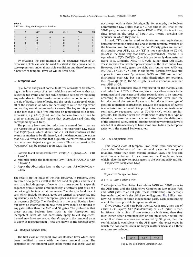
truth table (TTT), with which the values of temporal expressionscan be computed. TTTs are similar to classical Boolean truthtables, except the number of values is extended to account for thesequence values of the events. 0 continues to represent ‘‘false’’, i.e.an event that has not occurred, but ‘‘true’’ is now represented bythe positive integers, and the value of the integer is the sequencevalue. It is then possible to use a TTT to define the behaviour of thethree temporal gates and two existing logical gates, as shown inTable 1.
As can be seen from the table, X.Y is true whenever both X andY occur, and takes on the maximum sequence value of its inputs inthat case (since it is only true once all of its inputs have occurred).X+Y is true whenever at least one of its inputs occurs, and takes onthe minimum input sequence value (i.e. the value of the first inputto occur). XoY is true only if X precedes Y, and takes on thesequence value of its rightmost input; X&Y is true only if all inputsoccur simultaneously and so also has that same sequence value;and X|Y is true if either X is true and Y is not or X occurs before Y,taking on the sequence value of X in either case.
ARTICLE IN PRESS
Table 1A TTT describing the five gates in Pandora.
X Y X.Y X+Y XoY X&Y X|Y
0 0 0 0 0 0 0
0 1 0 1 0 0 0
1 0 0 1 0 0 1
1 1 1 1 0 1 0
1 2 2 1 2 0 1
2 1 2 1 0 0 0
M. Walker, Y. Papadopoulos / Control Engineering Practice 17 (2009) 1115–1125 1119
By enabling the computation of the sequence value of anexpression, TTTs can also be used to establish the equivalence oftwo expressions under all possible conditions and therefore provea new set of temporal laws, as will be seen next.
3. Temporal laws
Qualitative analysis of normal fault trees consists of transform-ing a tree into a group of cut sets, which are sets of events that cancause the top event, and then reducing these cut sets by removingany redundancies. This transformation and reduction is done withthe aid of Boolean laws of logic, and the result is a group of MCSs;all of the events in an MCS are necessary to cause the top event,and so they contain no redundant events. The key to this processis the fact that a fault tree can also be represented as a logicalexpression, e.g. (A+C).(B+A), and the Boolean laws can then beused to manipulate and reduce that expression (and thus thecorresponding fault tree).
The primary laws used for reduction in normal fault trees arethe Absorption and Idempotent Laws. The Absorption Law statesthat X+(X.Y)3X, which allows one cut set that contains all theevents in another to be eliminated, and the Idempotent Law statesthat X.X3X, which means that duplicate events within a cut setcan be reduced to just a single occurrence. Thus an expression like(A+C).(B+A) can be reduced to its MCS like so:
1.
Convert to cut sets (Distributive Laws): (A+C).(B+A)3A.B+C.B+A.A+C.A.2.
Minimise using the Idempotent Law: A.B+C.B+A.A+C.A3A.B+C.B+A+C.A.3.
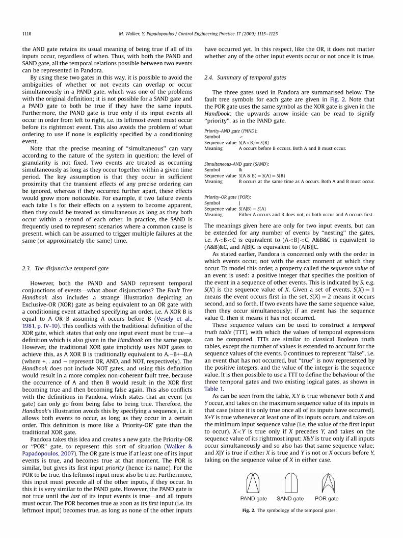
X.Y X<Y X&Y Y<X
Fig. 3. The Conjunctive Completion Law.
Apply the Absorption Law to the cut sets: A.B+C.B+A+C.A3C.B+A.
The results are the MCSs of the tree. However, in Pandora, thereare three new gates as well as the AND and OR gates, and the cutsets may include groups of events that must occur in a specificsequence or must occur simultaneously; effectively, part or all of acut set might be in a certain sequence. Therefore, in Pandora, cutsets which include temporal gates are termed cut sequences, andequivalently an MCS with temporal gates is known as a minimal
cut sequence (MCSQ). The Handbook lists the usual Boolean laws,but gives no information on how these laws should be applied toany gates other than the AND and OR gates. The problem is thatthese existing Boolean laws, such as the Absorption andIdempotent Laws, do not necessarily apply to cut sequences;instead, new laws are needed that do apply to the temporal gatesto allow us to reduce them. These are known as the temporal laws.
3.1. Modified Boolean laws
The first class of temporal laws are Boolean laws which havebeen modified to work with the three temporal gates. Thesemantics of the temporal gates often means that these laws do
not always work as they did originally; for example, the BooleanCommutative Law states that X.Y3Y.X; this is still true of theSAND gate, but when applied to the PAND or POR, this is not true,since reversing the order of inputs also means reversing thesequence in which they occur.
Instead, TTTs can be used to determine new equivalencesbetween temporal expressions, and so create temporal versions ofthe Boolean laws. For example, the two Priority gates are not leftdistributive over AND, e.g. Xo(Y.Z) is not equivalent to (XoY).(XoZ) in the same way that X+(Y.Z)3(X+Y).(X+Z). Instead, it isequivalent to Y.(XoZ)+Z.(XoY), which can be easily demonstratedusing TTTs. Similarly, X|(Y.Z)3X|Y+X|Z rather than (X|Y).(X|Z).These are therefore new temporal versions of the Distributive Law.However, the Priority gates are right distributive over AND, e.g.(Y.Z)oX3(YoX).(ZoX), and so the normal Distributive Law stillapplies in those cases. By contrast, PAND and POR are both leftdistributive over OR, but not right distributive; for example,X|(Y+Z)3(X|Y).(X|Y). The SAND gate is not distributive, whetherover AND or OR.
This class of temporal laws is very useful for the manipulationand reduction of TFTs in Pandora, since they allow events to berearranged and duplicates and other redundancies to be removedaccording to the Absorption and Idempotent Laws, but theintroduction of the temporal gates also introduces a new type ofpossible reduction: contradiction. Because the sequence of eventsis now taken into account, it is possible to have combinations ofcontradictory sequences such as (XoY).(YoX), which are im-possible. The Boolean laws are insufficient to detect this type ofsituation, because these contradictions arise from the definitionsof the temporal gates. Instead, another set of new temporal laws isneeded. It is also necessary to have some laws to link the temporalgates with the normal Boolean gates.
3.2. The Completion Laws
This second class of temporal laws come from observationsabout the definitions of the temporal gates and temporalrelations, rather than from existing Boolean laws. The first andmost fundamental set of these laws are the Completion Laws,which relate the new temporal gates to the existing AND and OR:
Conjunctive Completion Law:
X:Y 3 XoY þ X&Y þ YoX
Disjunctive Completion Law:
X þ Y 3 XjY þ X&Y þ Y jX
The Conjunctive Completion Law relates PAND and SAND gates tothe AND gate, and the Disjunctive Completion Law relates PORand SAND gates to an OR gate. These relationships are perhapsbest understood with the aid of some diagrams. Fig. 3 illustrateshow X.Y consists of three independent parts, each representingone of the three possible temporal relations:
If two events X and Y are both true (i.e. X.Y is true), then one ofeither XoY (Before), X&Y (Simultaneous), or YoX (After) is true.Intuitively, this is clear: if two events are both true, then theymust either occur simultaneously, or one must occur before theother. If all three relations are connected by OR gates, then thecombination is equivalent to the AND gate—the exact order inwhich the two events occur no longer matters, because all threerelations are included.

ARTICLE IN PRESS
X+Y X X<Y X&Y
X.Y
Y<X Y
X|Y Y|X
Fig. 4. The Disjunctive Completion Law.
Table 2A TTT showing the Completion Laws.
X Y X+Y X.Y X|Y XoY X&Y YoX Y|X XoY+X&Y+YoX X|Y+X&Y+Y|X X|Y+X&Y+YoX
0 0 0 0 0 0 0 0 0 0 0 0
0 1 1 0 0 0 0 0 1 0 1 0
1 0 1 0 1 0 0 0 0 0 1 1
1 1 1 1 0 0 1 0 0 1 1 1
1 2 1 2 1 2 0 0 0 2 1 1
2 1 1 2 0 0 0 2 1 2 1 2
M. Walker, Y. Papadopoulos / Control Engineering Practice 17 (2009) 1115–11251120
Fig. 4 shows the Disjunctive Completion Law. The shaded areain both figures represents X.Y, and it is possible to see how inFig. 4, X+Y consists of five mutually exclusive areas: either X aloneis true, Y alone is true, or one of the three components of X.Y istrue. However, four of these areas are covered by two POR gates,X|Y and Y|X; the disjunction of these two gates and a SAND gate istherefore equivalent to X+Y as a whole. The Completion Laws canbe proved by using TTTs, as seen in Table 2; if all the values in twocolumns in a TTT are the same, then the expressions representedby those columns (marked in bold) are equivalent.
There is also a third Completion Law in the table, shown in therightmost column of Table 2. It can be used to reduce complextemporal expressions when the occurrence of a second event isnot important:
X 3 XjY þ X&Y þ YoX
This Completion Law uses all three temporal gates, and isparticularly useful for eliminating a given factor from a numberof different cut sequences (Y in this case). It can also be extendedto three events:
X3XjY jZþ ðX&YÞjZþ ðX&ZÞjY
þ X&Y&Zþ YoðX&ZÞ þ ZoðX&YÞþ ðYoZÞoX þ ðY&ZÞoX þ ðZoYÞoX
þ ðYoXÞjZþ ðZoXÞjY
3.3. Further ‘‘Temporal’’ Laws
The Completion Laws are useful because they allow us toexpand Boolean gates into disjunctions of temporal gates and viceversa; they link the two types of gates together. But it is importantto remember that each of the three temporal relations aremutually exclusive: only one can be true at once. This isexemplified by the Laws of Mutual Exclusion, a set of laws whichindicate possible contradictions stemming from conjunctions ofdifferent temporal relations. The three basic ones are:
XoY :YoX 3 0
XoY :X&Y 3 0
YoX:X&Y 3 0
It is not possible for X to occur both before and after Y, or for it tooccur before Y and at the same time as Y. These situations lead tocontradictions—they are impossible, and can never be true.Similarly, Mutual Exclusion extends to the POR gate too, e.g.X|Y.YoX30. Another form of contradiction is also possible, and
this happens when the same event occurs more than once as aninput to a priority gate (i.e. a PAND or POR gate):
XoX 3 0
XjX 3 0
X&X 3 X
These are the Laws of Simultaneity, and are evident from thedefinitions of the gates: X cannot occur before X. However, it isperhaps best understood by looking at the sequence values; bothpriority gates are false if any of their inputs have the samesequence value. Since an event appearing twice as an input to agate will have the same sequence value in each case, the prioritygates are always false in these cases, no matter what other inputsthey have. By contrast, the SAND gate is not affected: X&X3X; inother words, it obeys the Idempotent Law as normal.
There is also another set of laws, the Laws of Extension. Theselaws are important when more than two events are being used,because they explicitly show any temporal relationships whichare implied by the temporal gates. For example, if X occurs beforeY and Y occurs before Z, then by extension, X must also occur beforeZ. In this case, it is equivalent to saying XoYoZ. The Laws alsoapply to the other two gates, like so:
XoY :YoZ 3 XoY :YoZ:XoZ
X&Y :Y&Z 3 X&Y :Y&Z:X&Z
XjY :Y jZ 3 XjY :Y jZ:XjZ
The Extension Laws are also used to identify cyclic contradictions,which are expressions that initially appear sound but are in factcontradictory. For example, XoY.YoZ.ZoX. This expression con-tains no immediate contradictions, but if followed through, eachevent must occur before and after the other two. This can beshown explicitly by first applying the Law of Extension (additionsare in bold):
XoY :YoZ:ZoX:XoZ:YoX:ZoY
And now there are contradictions, because there is a conjunctionof both XoY and YoX, for instance.
There are two other laws which can prove useful duringreduction: the Laws of POR Transformation and the Laws ofPriority. The first are a variant of the Absorption Laws, and dealwith the Absorption of a POR gate:
XjY :Y 3 XoY
XjY þ Y 3 X þ Y
This behaviour contrasts with the usual behaviour of the temporalgates under Absorption, i.e.:
XoY :X 3 XoY ; XoY þ X 3 X
X&Y :X 3 X&Y ; X&Y þ X 3 X
XjY :X 3 XjY ; XjY þ X 3 X
The difference comes from the fact that the leftmost input to aPOR gate has priority (i.e. it is the only one which must occur in aspecific sequence) and all of the others do not; Absorption works
ARTICLE IN PRESS
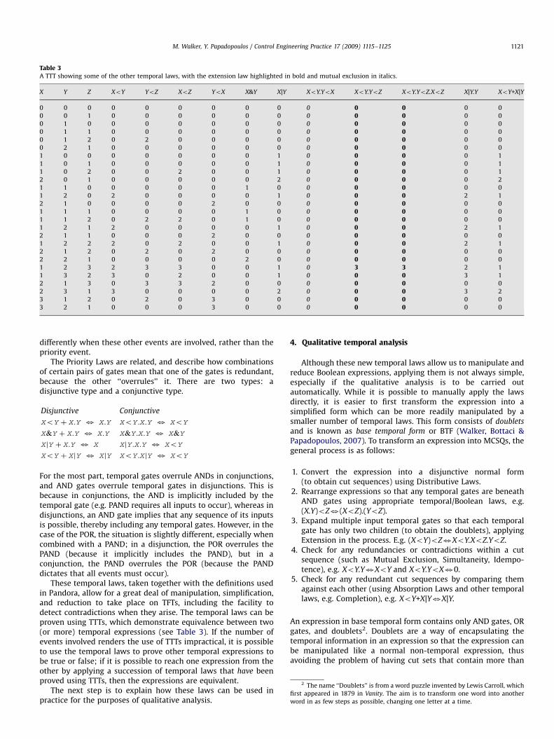
Table 3A TTT showing some of the other temporal laws, with the extension law highlighted in bold and mutual exclusion in italics.
X Y Z XoY YoZ XoZ YoX X&Y X|Y XoY.YoX XoY.YoZ XoY.YoZ.XoZ X|Y.Y XoY+X|Y
0 0 0 0 0 0 0 0 0 0 0 0 0 0
0 0 1 0 0 0 0 0 0 0 0 0 0 0
0 1 0 0 0 0 0 0 0 0 0 0 0 0
0 1 1 0 0 0 0 0 0 0 0 0 0 0
0 1 2 0 2 0 0 0 0 0 0 0 0 0
0 2 1 0 0 0 0 0 0 0 0 0 0 0
1 0 0 0 0 0 0 0 1 0 0 0 0 1
1 0 1 0 0 0 0 0 1 0 0 0 0 1
1 0 2 0 0 2 0 0 1 0 0 0 0 1
2 0 1 0 0 0 0 0 2 0 0 0 0 2
1 1 0 0 0 0 0 1 0 0 0 0 0 0
1 2 0 2 0 0 0 0 1 0 0 0 2 1
2 1 0 0 0 0 2 0 0 0 0 0 0 0
1 1 1 0 0 0 0 1 0 0 0 0 0 0
1 1 2 0 2 2 0 1 0 0 0 0 0 0
1 2 1 2 0 0 0 0 1 0 0 0 2 1
2 1 1 0 0 0 2 0 0 0 0 0 0 0
1 2 2 2 0 2 0 0 1 0 0 0 2 1
2 1 2 0 2 0 2 0 0 0 0 0 0 0
2 2 1 0 0 0 0 2 0 0 0 0 0 0
1 2 3 2 3 3 0 0 1 0 3 3 2 1
1 3 2 3 0 2 0 0 1 0 0 0 3 1
2 1 3 0 3 3 2 0 0 0 0 0 0 0
2 3 1 3 0 0 0 0 2 0 0 0 3 2
3 1 2 0 2 0 3 0 0 0 0 0 0 0
3 2 1 0 0 0 3 0 0 0 0 0 0 0
2 The name ‘‘Doublets’’ is from a word puzzle invented by Lewis Carroll, which
first appeared in 1879 in Vanity. The aim is to transform one word into another
word in as few steps as possible, changing one letter at a time.
M. Walker, Y. Papadopoulos / Control Engineering Practice 17 (2009) 1115–1125 1121
differently when these other events are involved, rather than thepriority event.
The Priority Laws are related, and describe how combinationsof certain pairs of gates mean that one of the gates is redundant,because the other ‘‘overrules’’ it. There are two types: adisjunctive type and a conjunctive type.
Disjunctive Conjunctive
XoY þ X:Y 3 X:Y XoY :X:Y 3 XoY
X&Y þ X:Y 3 X:Y X&Y :X:Y 3 X&Y
XjY þ X:Y 3 X XjY :X:Y 3 XoY
XoY þ XjY 3 XjY XoY :XjY 3 XoY
For the most part, temporal gates overrule ANDs in conjunctions,and AND gates overrule temporal gates in disjunctions. This isbecause in conjunctions, the AND is implicitly included by thetemporal gate (e.g. PAND requires all inputs to occur), whereas indisjunctions, an AND gate implies that any sequence of its inputsis possible, thereby including any temporal gates. However, in thecase of the POR, the situation is slightly different, especially whencombined with a PAND; in a disjunction, the POR overrules thePAND (because it implicitly includes the PAND), but in aconjunction, the PAND overrules the POR (because the PANDdictates that all events must occur).
These temporal laws, taken together with the definitions usedin Pandora, allow for a great deal of manipulation, simplification,and reduction to take place on TFTs, including the facility todetect contradictions when they arise. The temporal laws can beproven using TTTs, which demonstrate equivalence between two(or more) temporal expressions (see Table 3). If the number ofevents involved renders the use of TTTs impractical, it is possibleto use the temporal laws to prove other temporal expressions tobe true or false; if it is possible to reach one expression from theother by applying a succession of temporal laws that have beenproved using TTTs, then the expressions are equivalent.
The next step is to explain how these laws can be used inpractice for the purposes of qualitative analysis.
4. Qualitative temporal analysis
Although these new temporal laws allow us to manipulate andreduce Boolean expressions, applying them is not always simple,especially if the qualitative analysis is to be carried outautomatically. While it is possible to manually apply the lawsdirectly, it is easier to first transform the expression into asimplified form which can be more readily manipulated by asmaller number of temporal laws. This form consists of doublets
and is known as base temporal form or BTF (Walker, Bottaci &Papadopoulos, 2007). To transform an expression into MCSQs, thegeneral process is as follows:
1.
Convert the expression into a disjunctive normal form(to obtain cut sequences) using Distributive Laws.2.
Rearrange expressions so that any temporal gates are beneathAND gates using appropriate temporal/Boolean laws, e.g.(X.Y)oZ3(XoZ).(YoZ).3.
Expand multiple input temporal gates so that each temporalgate has only two children (to obtain the doublets), applyingExtension in the process. E.g. (XoY)oZ3XoY.XoZ.YoZ.4.
Check for any redundancies or contradictions within a cutsequence (such as Mutual Exclusion, Simultaneity, Idempo-tence), e.g. XoY.Y3XoY and XoY.YoX30.5.
Check for any redundant cut sequences by comparing themagainst each other (using Absorption Laws and other temporallaws, e.g. Completion), e.g. XoY+X|Y3X|Y.An expression in base temporal form contains only AND gates, ORgates, and doublets2. Doublets are a way of encapsulating thetemporal information in an expression so that the expression canbe manipulated like a normal non-temporal expression, thusavoiding the problem of having cut sets that contain more than

ARTICLE IN PRESS
Table 4Reduction of two doublets with the same events.
[X|Y] [Y|X] [XoY] [YoX] [X&Y] [Y&X]
[X|Y] Idempotent: [X|Y] Mut. Excl.: 0 Priority: [XoY] Mut. Excl.: 0 Mut. Excl.: 0 Mut. Excl.: 0
[Y|X] Mut. Excl.: 0 Idempotent: [Y|X] Mut. Excl.: 0 Priority: [YoX] Mut. Excl.: 0 Mut. Excl.: 0
[XoY] Priority: [XoY] Mut. Excl.: 0 Idempotent: [XoY] Mut. Excl.: 0 Mut. Excl.: 0 Mut. Excl.: 0
[YoX] Mut. Excl.: 0 Priority: [YoX] Mut. Excl.: 0 Idempotent: [YoX] Mut. Excl.: 0 Mut. Excl.: 0
[X&Y] Mut. Excl.: 0 Mut. Excl.: 0 Mut. Excl.: 0 Mut. Excl.: 0 Idempotent: [X&Y] Idempotent: [X&Y]
[Y&X] Mut. Excl.: 0 Mut. Excl.: 0 Mut. Excl.: 0 Mut. Excl.: 0 Idempotent: [X&Y] Idempotent: [Y&X]
M. Walker, Y. Papadopoulos / Control Engineering Practice 17 (2009) 1115–11251122
just AND gates. A doublet itself is simply a pair of eventsconnected by a single temporal gate, and is indicated by squarebrackets, e.g. [XoY]. Any expression containing temporal gatescan be converted into a set of doublets connected by either AND orOR gates—cut sequences. In so doing, the doubletisation of anexpression also means that complex hierarchies of temporal gatescan be flattened so that they only contain doublets and normalevents, with no temporal gates below other temporal gates, e.g.X|(Y&Z) becomes [X|Y]+[X|Z]+X.[Y|Z]+X.[Z|Y]. By simpli-fying and then abstracting the temporal information out of the cutsequence in this way, it is possible to treat doublets as basicevents and reduce them accordingly. It is also easier to see the realtemporal relations between events in base temporal form,because every temporal relation between each pair of events isrepresented by a separate doublet.
To convert an expression into doublets, it must be transformedinto a cut set-like format with any OR gates highest in theexpression, then AND gates, and then the three temporal gates(preferably in the order POR, PAND, and SAND). This rearranging isdone by applying the Distributive, Commutative, and AssociativeLaws as necessary. There are too many of these laws to list themall, but as an example, consider a fault tree represented by thefollowing expression:
TOP ¼ ðA:ððððXoYÞoZÞ þ BÞ þ ððC&DÞ&EÞÞÞ:ðFjðG þ HÞÞ
First the Associative Laws are applied to remove some of theunnecessary brackets, e.g. (X+Y)+Z3X+Y+Z. It is also possible toapply two temporal laws, (XoY)oZ3XoYoZ and (X&Y)&Z3
X&Y&Z:
TOP ¼ A:ððXoYoZÞ þ B þ ðC&D&EÞÞ:ðFjðG þ HÞÞ
However, this is still not in cut set format, since the top level gateis an AND gate. To be in cut set form, any OR gates must be on top,and all temporal gates at the bottom. To achieve this, someDistributive Laws must be applied, such as X.(Y+Z)3X.Y+X.Z:
TOP ¼ A:ðXoYoZÞ:ðFjðG þ HÞÞ þ A:B:ðFjðG þ HÞÞ
þ A:ðC&D&EÞ:ðFjðG þ HÞÞ
This is almost in cut set form, but there are still have OR gatesunderneath temporal gates. To rearrange this, it is necessary toapply another temporal Distributive law: X|(Y+Z)3(X|Y).(X|Z):
TOP ¼ A:ðXoYoZÞ:ðFjGÞ:ðFjHÞ þ A:B:ðFjGÞ:ðFjHÞ
þ A � ðC&D&EÞ:ðFjGÞ:ðFjHÞ
This expression is now in the correct format for doubletisation.The POR gates already only have two children each, so these canbe converted directly to doublets; the SAND and PAND gates havethree children, and need to be expanded according to the Law ofExtension first. The end result is three doubletised cut sequencesas follows:
TOP ¼ A:½XoY �:½YoZ�:½XoZ�:½FjG�:½FjH � þ A:B:½FjG�:½FjH �
þ A:½C&D�:½D&E�:½C&E�:½FjG�:½FjH �
Once an expression is in BTF like this, it is a simple matter toreduce it. First, all events not part of doublets are comparedagainst all the doublets; if any are contained within a doublet,they are redundant and can be removed according to the temporalAbsorption Laws (e.g. X.[XoY]3[XoY]). The only exceptionis the POR Transformation Law—if an event occurs on the rightof a POR, it is absorbed and the doublet changed to a PAND(e.g. Y.[X|Y]3[XoY]).
Next, all the doublets are compared with each other. Becausethe Extension Law is applied during the conversion of theexpression into doublets, all temporal relations are explicitlyrepresented by doublets. Any PAND or POR doublet containingtwo identical events is an immediate contradiction according tothe Laws of Simultaneity; any SAND doublet reduces to just asingle event by the same law (so that [X&X]3X, for instance). Anytwo doublets each containing the same pair of events may lead toa reduction of some kind, so Idempotence, Mutual Exclusion, andPriority must also be checked for, as indicated by Table 4.
If there is a contradiction in the cut sequence, either fromSimultaneity or Mutual Exclusion, then the whole cut sequence isalso contradictory according to the basic Boolean law X.030.Then, according to the law X+03X, the entire cut sequence can beremoved, effectively eliminating any contradictions.
Once each cut sequence has been minimised, the final step is tocompare the cut sequences against each other. Just as with normalBoolean cut sets, if any cut sequence wholly contains another,then the largest one is redundant, e.g. X.[YoZ]+[YoZ]3[YoZ].Extra care must be taken, however, to ensure that the doublets arecompared correctly; doublets usually have to contain the sameevents in the same order to be redundant, so X.[YoZ]+[ZoY], forinstance, cannot be reduced further. The exceptions to this areSAND gates (in which order is irrelevant, since [X&Y]3[Y&X]) andinstances of the Priority Law, e.g. [X|Y]+[XoY] 3 [X|Y]; if two cutsequence are otherwise the same, but one contains a PAND wherethe other contains a POR, the PAND cut sequence can be removed;for example:
A:½B&C�:½CoD� þ A:½B&C�:½CjD� 3 A:½B&C�:½CjD�
This process will result in the set of MCSQs for the fault tree.
5. Example
To see how Pandora works in practice, consider the exampletriple-module standby redundant system shown earlier in Fig. 1.This system provides a useful illustration of the benefits ofPandora because the standby redundancy modelled in this systemis a classic way of achieving fault tolerance. The system is alsogeneric, an example of a design pattern rather than a specificsystem; the components are abstract and therefore independentof technology, and could be replaced by specific sensors,controllers, actuators and other types of component. Finally, the
ARTICLE IN PRESS
M. Walker, Y. Papadopoulos / Control Engineering Practice 17 (2009) 1115–1125 1123
results obtained from this example can easily be generalised tocover the case of N-module standby redundancy.
In the Introduction, it was stated that the order in whichcomponents fail in this system can have a large impact on thefailure behaviour of the system, an impact which is ignored intraditional FTA. This section demonstrates how it is possible tocapture the consequences of this behaviour by using Pandora.
For the purposes of failure modelling, the failure behaviour ofcomponents in the system is described using a simplified form ofthe HiP-HOPS notation (Walker & Papadopoulos, 2006). In HiP-HOPS, faults at component outputs (output deviations) are linkedto a combination of faults at component inputs (input deviations)or internal failures (basic events). Deviations are indicated by aletter describing the failure class, e.g. O for Omission, C forCommission, and then the component, so that O�S1 means‘‘Omission of signal from Sensor 1’’. Basic events are indicated inthis paper by the component name, so that A is an internal failureof the primary component A (a short circuit, for instance). Thefailure behaviour of the system is therefore as follows:
Component A
O�A ¼ O�I+A
–Omission of output from A is caused by an omission of input or internal
failure.
Component S1
O�S1 ¼ S1oO�A+S1&O�A
–An omission from Sensor 1 is caused by an internal failure before or at the
same time as an omission from A (i.e. the sensor is incapable of detecting
O�A).
StartB�S1 ¼ O�A
–This is an expected event, rather than a failure, and is the signal to activate
standby B.
Component B
Odet�B ¼ StartB�S1o(B+O�I)
–Detectable omission from B is caused by a failure of B or a lack of input as
long as B has been activated.
Ound�B ¼ O�S1+(B+O�I)oStartB�S1+(B+O�I)&StartB�S1
–Undetectable omission from B is caused by an omission from Sensor 1 or a
failure of B or a lack of input before or at the same time as B is activated.
Component S2
O�S2 ¼ S2oOdet�B+S2&Odet�B
–An omission from Sensor 2 is caused by an internal failure before or at the
same time as a detectable omission from B (i.e. the sensor is incapable of
detecting Odet�B).
StartC�S2 ¼ Odet�B
–This is an expected event, not a failure, and is the signal to activate standby C.
Component C
O�C ¼ O�S2+(C+O�I).StartC�S2
--An omission from C is caused by an omission from Sensor 2 (in which case C
will not be started) or a failure of C or a lack of input when C is active.
Component D
O�D ¼ D+Ound�B+O�C
–An omission from D is caused either by an internal failure, an undetectable
omission from B, or an omission from C.
Note that the failure behaviour of seemingly identical componentsmay differ depending on the role of these components in a model.Thus, even though components B and C are likely identical interms of hardware and function, the effects of their failures aredifferent because they have different roles within the system (andso an undetectable failure of B means that C will not be activated,whereas once C is activated, any failure of C will cause systemfailure, whether undetectable or not).
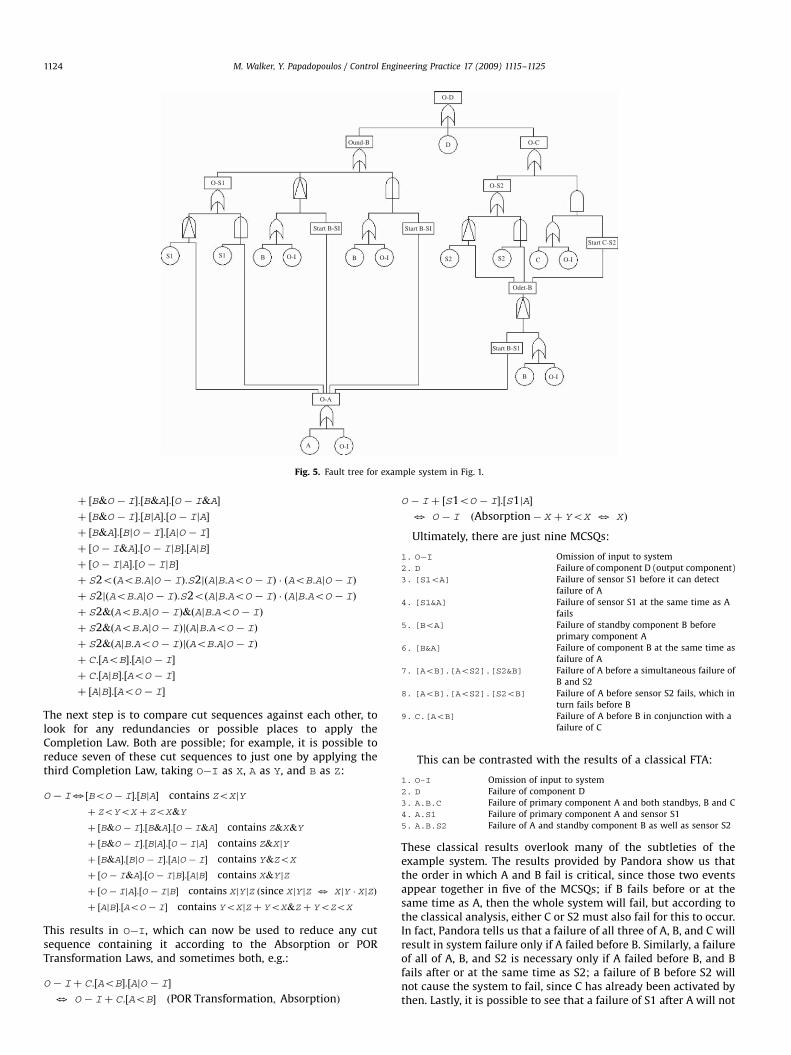
HiP-HOPS takes this information and constructs a fault treefrom it for the top event ‘‘O�D’’, i.e. an omission from the systemoutput, component D. This is done by substituting input
deviations for corresponding output deviations, e.g. O�A inStartB�S1 can be replaced by (A+O�I). This fault tree is shownin Fig. 5, and the expression represented by the tree is as follows:
O � D ¼ D þ S1oðO � I þ AÞþ S1&ðO � I þ AÞ
þ ðB þ O � IÞoðO � I þ AÞ þ ðB þ O � IÞ&ðO � I þ AÞþ S2oððO � I þ AÞoðB þ O � IÞÞþ S2&ððO � I þ AÞoðB þ O � IÞÞþ ðC þ O � IÞ:ððO � I þ AÞoðB þ O � IÞÞÞ
The first task, as described in the last section, is to rearrange thisexpression into cut set format, with ORs uppermost and temporalgates lowest. However, because the resulting expression would betoo large to present here, only a part of this process will be shown.For example, taking only the first line of O�D, rearranging S1o(O�I+A) requires the temporal Distributive Law Xo(Y+Z)3
(X|Y).(X|Z).(Y+Z) and rearranging S1&(O�I+A) requires thetemporal Distributive Law X&(Y+Z)3(X&Y&Z)+(X&Y|Z)+
(X&Z|Y). To rearrange (B+O�I)o(O�I+A), another DistributiveLaw must be used first, (Y+Z)oX3YoX+ZoX. Sometimes theBoolean Distributive Laws are needed too, i.e. X.(Y+Z)3-
X.Y+X.Z. The first two lines of expression O�D thereforebecome:
O-D ¼ D þ ðS1jO � IÞ:ðS1jAÞ:O � I
þ ðS1jO � IÞ:ðS1jAÞ:Aþ ðS1&O � I&AÞ
þ ðS1&O � IjAÞ þ ðS1&AjO � IÞ þ ðBjO � IÞ � ðBjAÞ:O � I
þ ðBjO � IÞ:ðBjAÞ � Aþ ðO � IjO � IÞ � ðO � IjAÞ:O � I
þ ðO � IjO � IÞ:ðO � IjAÞ:Aþ � � �
The next step is to convert the expression into doublets, so that itis easier to deal with redundancies and contradictions. In mostcases this is straightforward, but if there are temporal gates withmore than two basic event inputs, it is necessary to break themup: (S1&O�I&A)3[S1&O�I].[S1&A].[O�I&A]. This is alsotrue of any multiple temporal gates, e.g. (S1&O�I|A) becomes(according to the Laws of Extension): [S1&O�I].[S1|A].
[O�I|A].Once converted into doublets, any possible reductions should
be checked for. First, it is important to check for redundancieswithin each cut sequence: Idempotence, Simultaneity, POR Trans-formation and Absorption. Given the first two lines of the originalexpression, now transformed into doublets:
O � D ¼ D þ ½S1jO � I�:½S1jA�:O � I þ ½S1jO � I�:½S1jA�:A
þ ½S1&O � I�:½S1&A�:½O � I&A�
þ ½S1&O � I�:½S1jA�:½O � IjA�
þ ½S1&A�:½S1jO � I�:½AjO � I�
þ ½BjO � I�:½BjA�:O � I
þ ½BjO � I�:½BjA�:Aþ ½O � IjO � I�:½O � IjA� � O � I
þ ½O � IjO � I�:½O � IjA�:A
There are two places where the Law of Simultaneity is beingviolated ([O�I|O�I]30) and instances of POR Transformation,e.g.: [S1|O�I].[S1|A].O�I3[S1oO�I]�[S1|A]. Once thisphase is complete, the result is a set of doubletised cut sequencesthat each contains no redundancies:
O � D ¼ D þ ½S1oO � I�:½S1jA�
þ ½S1jO � I�:½S1oA�
þ ½S1&O � I�:½S1&A�:½O � I&A�
þ ½S1&O � I�:½S1jA�:½O � IjA�
þ ½S1&A�:½S1jO � I�:½AjO � I�
þ ½BoO � I�:½BjA�
þ ½BjO � I�:½BoA�
ARTICLE IN PRESS
O-S1
S1 S1 B O-I O-I O-I
O-I
CS2S2
O-S2
O-COund-B D
O-D
B
Start B-SI Start B-SI
Odet-B
Start C-S2
Start B-S1
O-A
B
O-IA
Fig. 5. Fault tree for example system in Fig. 1.
M. Walker, Y. Papadopoulos / Control Engineering Practice 17 (2009) 1115–11251124
þ ½B&O � I�:½B&A�:½O � I&A�
þ ½B&O � I�:½BjA�:½O � IjA�
þ ½B&A�:½BjO � I�:½AjO � I�
þ ½O � I&A�:½O � IjB�:½AjB�
þ ½O � IjA�:½O � IjB�
þ S2oðAoB:AjO � IÞ:S2jðAjB:AoO � IÞ � ðAoB:AjO � IÞ
þ S2jðAoB:AjO � IÞ:S2oðAjB:AoO � IÞ � ðAjB:AoO � IÞ
þ S2&ðAoB:AjO � IÞ&ðAjB:AoO � IÞ
þ S2&ðAoB:AjO � IÞjðAjB:AoO � IÞ
þ S2&ðAjB:AoO � IÞjðAoB:AjO � IÞ
þ C:½AoB�:½AjO � I�
þ C:½AjB�:½AoO � I�
þ ½AjB�:½AoO � I�
The next step is to compare cut sequences against each other, tolook for any redundancies or possible places to apply theCompletion Law. Both are possible; for example, it is possible toreduce seven of these cut sequences to just one by applying thethird Completion Law, taking O�I as X, A as Y, and B as Z:
O � I3½BoO � I�:½BjA� contains ZoXjY
þ ZoYoX þ ZoX&Y
þ ½B&O � I�:½B&A�:½O � I&A� contains Z&X&Y
þ ½B&O � I�:½BjA�:½O � IjA� contains Z&XjY
þ ½B&A�:½BjO � I�:½AjO � I� contains Y&ZoX
þ ½O � I&A�:½O � IjB�:½AjB� contains X&Y jZ
þ ½O � IjA�:½O � IjB� contains XjY jZ ðsince XjY jZ 3 XjY � XjZÞ
þ ½AjB�:½AoO � I� contains YoXjZþ YoX&Zþ YoZoX
This results in O�I, which can now be used to reduce any cutsequence containing it according to the Absorption or PORTransformation Laws, and sometimes both, e.g.:
O � I þ C:½AoB�:½AjO � I�
3 O � I þ C:½AoB� ðPOR Transformation; AbsorptionÞ
O � I þ ½S1oO � I�:½S1jA�
3 O � I ðAbsorption� X þ YoX 3 XÞ
Ultimately, there are just nine MCSQs:
1. O�I
Omission of input to system2. D
Failure of component D (output component)3. [S1oA]
Failure of sensor S1 before it can detectfailure of A
4. [S1&A]
Failure of sensor S1 at the same time as Afails
5. [BoA]
Failure of standby component B beforeprimary component A
6. [B&A]
Failure of component B at the same time asfailure of A
7. [AoB].[AoS2].[S2&B]
Failure of A before a simultaneous failure ofB and S2
8. [AoB].[AoS2].[S2oB]
Failure of A before sensor S2 fails, which inturn fails before B
9. C.[AoB]
Failure of A before B in conjunction with afailure of C
This can be contrasted with the results of a classical FTA:
1. O-I
Omission of input to system2. D
Failure of component D3. A.B.C
Failure of primary component A and both standbys, B and C4. A.S1
Failure of primary component A and sensor S15. A.B.S2
Failure of A and standby component B as well as sensor S2These classical results overlook many of the subtleties of theexample system. The results provided by Pandora show us thatthe order in which A and B fail is critical, since those two eventsappear together in five of the MCSQs; if B fails before or at thesame time as A, then the whole system will fail, but according tothe classical analysis, either C or S2 must also fail for this to occur.In fact, Pandora tells us that a failure of all three of A, B, and C willresult in system failure only if A failed before B. Similarly, a failureof all of A, B, and S2 is necessary only if A failed before B, and Bfails after or at the same time as S2; a failure of B before S2 willnot cause the system to fail, since C has already been activated bythen. Lastly, it is possible to see that a failure of S1 after A will not
ARTICLE IN PRESS
M. Walker, Y. Papadopoulos / Control Engineering Practice 17 (2009) 1115–1125 1125
cause the system to fail on its own, which is contrary to theclassical results. The Pandora results are thus significantly moreaccurate.
The results obtained by Pandora differ in several ways from thosepossible using other approaches. DFTs are primarily a quantitativeanalysis technique and so would not be able to produce MCSQs inthis way, although if probabilistic failure data was available, it wouldpresumably be possible to arrive at an estimate for the systemreliability. The TFT approach is meant for a system in operation, not amodel of a system under design; similarly, using the TAND gatewould mean representing events as having a finite duration, whichmeans making different assumptions about the system behaviourand this would likely produce different results.
To further evaluate the potential of Pandora, the technique wasapplied to a model of a multi-modal vehicle steer-by-wire system,which has been previously analysed using traditional combinator-ial FTA techniques (Parker, Walker, Papadopoulos, & Grante, 2006).Early results from a partial analysis of this model and comparisonswith results gained via classical FTA show that similar benefitscan be expected to those displayed in the example, in terms ofimproving the clarity, correctness and accuracy of the analysis.However, because the analysis in Pandora is of a much finer grain,issues of computational complexity must be addressed in thefuture with the development of efficient analysis algorithms, sothat an automated analysis process becomes feasible for large andcomplex systems.
The industrial potential of Pandora is also investigated in theATESST-2 FP7 European research project where the technique iscurrently being applied to automotive brake-by-wire systems.Such systems were identified as good applications for theapproach because the sequence of underlying causal events canhave considerable impact on the effects of failures on thevehicle as well as the criticality of those failures: due to thevehicle dynamics, different outcomes can arise if the brakes fail inone sequence than if they fail in another. These distinctionsare difficult—if not impossible—to adequately represent usingstandard fault trees.
6. Conclusion
It has long been recognised in the Fault Tree Handbook thatclassical combinatorial fault trees cannot capture the potentiallycritical significance of the temporal ordering of failures in asystem. Although the Handbook proposed dynamic gates toaddress the problem, these gates were rarely used due to thelack of any information in the Handbook on how to performqualitative or quantitative analysis on them.
This paper presented Pandora, an approach that enablesmodelling and analysis of dynamic failure behaviour in systemsvia extensions to Boolean logic, as was originally envisaged in theFault Tree Handbook. Pandora uses only three gates to describetemporal relationships between events, a PAND, a POR and an SANDgate; it also defines the simple notion of a relative ordering of events,in which it is only necessary to determine whether one event camebefore, after, or at the same time as another. Furthermore, attemptsat a formal underpinning of these gates in Pandora can be found inMerle and Roussel (2007) and Walker et al. (2007).
Temporal order is represented using a sequence value, which isan integer indicating the order in which an event occurs within aset. It was shown that sequence values can be used in TemporalTruth Tables (TTTs) to compute the truth value of expressions thatconnect events with classical Boolean and temporal operators.TTTs have been used to prove a set of ‘temporal’ laws in Pandoralogic, including extended versions of traditional Boolean laws likethe Distributive and Absorption Laws as well as new laws specific
to the PAND, SAND, and POR gates. Qualitative analysis oftemporal fault trees in Pandora is possible by using thesetemporal laws. The result is a set of minimal cut sequences(MCSQs), which are analogous to traditional minimal cut sets,except for the fact that they contain temporal gates. MCSQstherefore represent the smallest sequence of events necessary tocause the top event, and are more accurate and more informativethan traditional minimal cut sets. This is important not in onlyitself but also as a precursor for later quantitative analysis, as itshould result in a less pessimistic estimate of system reliability.
In the future, the aim is to improve the performance of thequalitative analysis algorithm in an attempt to match theefficiency of existing non-temporal FTA techniques, which willallow Pandora to be applied to larger and more complex systemsthan those it has been used with thus far. In addition, furtherextensions to Pandora are planned in order to incorporatequantitative analysis capabilities. The goal is to produce acomprehensive tool for fault tree analysis of complex dynamicsystems. Current steps towards transferring this technology toindustry include integration of PANDORA with HiP-HOPS, amature tool for automated safety analysis, and work in ATESST-2towards integration of PANDORA with EAST-ADL2 an automotivearchitecture description language which is likely to influence thedesign of automotive systems in the near future.
Acknowledgement
This work was supported by the EU Projects SAFEDOR (GrantIP-516278) and ATESST-2 (Grant 224442).
References
Fussel, J. B., Aber, E. F., & Rahl, R. G. (1976). On the quantitative analysis of Priority-AND failure logic. IEEE Transactions on Reliability, R-25/5, 324–326.
Long, W., Sato, Y., & Horigome, M. (2000). Quantification of sequential failure logicfor fault tree analysis. Reliability Engineering & System Safety, 67, 269–274.
Manian, R., Dugan, J. B., Coppit, D., & Sullivan, K. J. (1998). Combining varioussolution techniques for dynamic fault tree analysis of computer systems. InThird IEEE international high-assurance systems engineering symposium (p. 21),Washington, DC, November 13–14.
Merle, G., & Roussel, J.-M. (2007). Algebraic modelling of temporal fault trees. InFirst IFAC workshop on dependable control of discrete systems (DCDS’07) (pp.175–180), Paris, France, June.
Palshikar, G. K. (2002). Temporal fault trees. Information and Software Technology,44, 137–150.
Parker, D., Walker, M., Papadopoulos, Y., & Grante, C. (2006). Component-based,automated FMEA of advanced active safety systems. In FISITA’06, 31st worldautomotive congress, Yokohama.
Sullivan, K., Dugan, J., & Coppit, D. (1999). The Galileo fault tree analysis tool. InProceedings of IEEE international symposium of fault tolerant computing, FTC-29(pp. 232–235), June.
Tang, Z., & Dugan, J. B. (2004). Minimal cut set/sequence generation for dynamicfault trees. In Annual reliability and maintainability symposium proceedings.
Vesely, W. E., Goldberg, F. F., Roberts, N. H., & Haasl, D. F. (1981). Fault treehandbook. Washington, DC, USA: US Nuclear Regulatory Commission.
Vesely, W. E., Stamatelatos, M., Dugan, J. B., Fragola, J., Minarick, J., & Railsback, J.(2002). Fault tree handbook with aerospace applications. NASA Office of Safetyand Mission Assurance, USA.
Walker, M., Bottaci, L., & Papadopoulos, Y. I. (2007). Compositional temporal faulttree analysis. SAFECOMP 2007. In Computer safety, reliability, and security (pp.106–119). Berlin/Heidelberg: Springer.
Walker, M., & Papadopoulos, Y .I. (2006). Pandora: The time of priority-AND gates.In INCOM 2006 (pp. 237–242), France.
Walker, M., & Papadopoulos, Y. I. (2007). Pandora 2: The time of priority-OR gates.In First IFAC workshop on dependable control of discrete systems (DCDS’07) (pp.169–174), Paris, France, June.
Wijayarathna, P. G., Kawat, Y., Santosa, A., & Isogai, K. (1997). Representing relativetemporal knowledge with the tand connective. In Eighth Ireland conference onartificial intelligence (AI-97) (Vol. 2, pp. 80–87), September.
Wijayarathna, P. G., & Maekawa, M. (2000). Extending fault trees with anAND–THEN gate. In Proceedings of the 11th international symposium on softwarereliability engineering (ISSRE’00).
Worrell, R. B., & Stack, D. W. (1978). A SETS user manual for the fault tree analyst. InNUREG CR-04651.