quantum communication towards - rero doc · universit´e de genev`e faculte´ des sciences groupe...
TRANSCRIPT

Universit´ eve e des Sciencese de Gen` Facult´
Groupe de Physique Appliquee Professeur N. Gisin
Quantum Communication
towards
real-world application
Thesepresentee a la Faculte des sciences de l’Universite de Geneve
pour obtenir le grade de Docteur es sciences, mention physique
par
Jeroen Anton Willem van Houwelingende
Leiden / Pays-Bas
These N° ????
GeneveAtelier de reproduction de la Section de physique
Avril 2008


“Light thinks it travels faster than anything but it is wrong. No matter how fastlight travels, it finds the darkness has always got there first, and is waiting for it.”
Terry Pratchett, Reaper Man

Abstract
This thesis is devoted to the development and study of quantum optical tech-niques that allow the use of quantum communication protocols such as a quantumrepeater in out-of-the-lab conditions. Up until now almost all experiments in thisresearch field were inside the laboratory. The experiments performed in this the-sis aimed to overcome the particular problems that can arise from non-laboratoryenvironments and investigate if there are unexpected complications involved in this.
The first experiment we performed was an entanglement swapping experimentinside the laboratory, but using systems that we believe are suitable for out-of-the-lab use. In order to provide a proof of principle of the employed techniques we usedstandard single mode optical fibers to simulate a ‘real world’ telecommunicationenvironment. The results of this experiment showed that indeed the chosen systemswork in such situations.
In our second experiment we investigated a new technique of performing Bellstate measurements. The technique was found to work but the usefulness for realworld experiments is hindered by the added losses with regards to more basic Bellstate measurements. The technique might have applications in quantum informationprotocols that require more than one Bell state to be measured.
Next we performed the first teleportation experiment that was performed out ofthe lab that uses prior entanglement distribution. A qubit was teleported from thelaboratory to a Swisscom switching station located 500m away from the lab. Forthis experiment the qubit was created by a different laser pulse than the entangledpair. This experiment again showed the robustness of our systems in real worldenvironments and effectively dealt with some of the problems that arise from usingmultiple sites. The only remaining non real-world part of this experiment is that allphotons were created in the same lab.
The final part of this work shows the progress made in developing photon-pairsources that can be separated by significant distances. This is required to make atrue quantum relay or repeater in which every link is located at a different location.
Some other contributions made during this thesis are tests of a new type of semi-conductor photon-pair sources. Also some fundamental Bell test were performedthat test some alternative theories to explain correlations found in experiments.
The overall conclusion of this thesis is that the techniques developed are useful forlong distance quantum communication in general and specifically for out-of-the-labapplication.
ii


Acknowledgments
There are a lot of people I would like to thank for their support during my timespent in Geneva, both on a professional and a personal level. Here are some of them.
First of all I would like to thank Nicolas Gisin for accepting me into his groupand both him and Hugo Zbinden for their guidance during my time spend here. Ialso thank Hugo for making me more conscience of being ‘green’ and environmentalissues in general.
I’d like to thank Ivan Marcikic and Hughues de Riedmatten for teaching me thebasics of quantum communication when I arrived in Geneva and for forcing metoo speak French. Alexios Beveratos for his insightful ways of working and RobertThew for his willingness to help others even if he is already buried under a pile ofpaperwork.
I want to thank the rest of GAP-optique I worked with on a regular bases forthe interesting discussions, helping hands and a good working atmosphere; OlivierLandry, Nicolas Brunner and Mattheaus Halder in particular. Also I thank DanielSalart and Sebastien Tanzilli for being good lab-mates.
Electronics and mechanics are not my speciality and because of this I’m verygrateful for all the support given to me by Claudio Barreiro and Jean-Daniel Gautier.
I especially want to thank the Geneva Flying Disc Wizards, WizToo and CodeWizfor their friendship. It was always great to be able to completely distract myselffrom work with such great individuals.
Finally I want to thank my parents and sister for all the help from abroad, visitsand general interest which where invaluable to me.
iv

Contents
Abstract ii
Acknowledgments iv
1 Introduction 1
1.1 Quantum Communication and Information . . . . . . . . . . . . . . . 1
1.2 This thesis . . . . . . . . . . . . . . . . . . . . . . . . . . . . . . . . . 3
2 Qubits and time-bins 5
2.1 Qubits . . . . . . . . . . . . . . . . . . . . . . . . . . . . . . . . . . . 5
2.1.1 Stationary-(qu)bit implementations . . . . . . . . . . . . . . . 6
2.1.2 Flying-(qu)bit implementations . . . . . . . . . . . . . . . . . 6
2.1.3 Alternative time-bin creation . . . . . . . . . . . . . . . . . . 10
3 Photon-pair sources and single photons 11
3.1 Introduction . . . . . . . . . . . . . . . . . . . . . . . . . . . . . . . . 11
3.2 Single photon sources . . . . . . . . . . . . . . . . . . . . . . . . . . . 12
3.3 Photon-pair sources . . . . . . . . . . . . . . . . . . . . . . . . . . . . 13
3.3.1 Spontaneous parametric downconversion . . . . . . . . . . . . 13
3.3.2 Alternative sources . . . . . . . . . . . . . . . . . . . . . . . . 14
3.3.3 Frequency upconversion . . . . . . . . . . . . . . . . . . . . . 15
4 Single Photon Detection 17
4.1 Introduction . . . . . . . . . . . . . . . . . . . . . . . . . . . . . . . . 17
4.2 Avalanche photodetectors . . . . . . . . . . . . . . . . . . . . . . . . 18
4.2.1 Modes of operation . . . . . . . . . . . . . . . . . . . . . . . . 18
4.3 Alternative detectors . . . . . . . . . . . . . . . . . . . . . . . . . . . 20
5 Entanglement 25
5.1 Time-bin entanglement . . . . . . . . . . . . . . . . . . . . . . . . . . 25
5.1.1 Bell-states . . . . . . . . . . . . . . . . . . . . . . . . . . . . . 26
5.2 Other types of entanglement . . . . . . . . . . . . . . . . . . . . . . . 26
v

5.3 Tests of entanglement . . . . . . . . . . . . . . . . . . . . . . . . . . 27
6 Long distance entanglement swapping [A] 29
6.1 Introduction . . . . . . . . . . . . . . . . . . . . . . . . . . . . . . . . 29
6.2 Entanglement swapping . . . . . . . . . . . . . . . . . . . . . . . . . 30
6.2.1 Experimental setup . . . . . . . . . . . . . . . . . . . . . . . . 30
6.2.2 Results and conclusions . . . . . . . . . . . . . . . . . . . . . 34
7 Three Bell-state analyzer [B, C] 37
7.1 Bell-state analyzers . . . . . . . . . . . . . . . . . . . . . . . . . . . . 37
7.1.1 Beamsplitter Bell-state analyzer . . . . . . . . . . . . . . . . 37
7.1.2 The three Bell-State analyzer . . . . . . . . . . . . . . . . . . 39
7.2 Quantum Teleportation . . . . . . . . . . . . . . . . . . . . . . . . . . 42
7.3 Results and conclusion . . . . . . . . . . . . . . . . . . . . . . . . . . 44
8 Out-of-the-lab Teleportation [D] [P1-P3] 49
8.1 Introduction . . . . . . . . . . . . . . . . . . . . . . . . . . . . . . . . 49
8.2 Experimental improvements . . . . . . . . . . . . . . . . . . . . . . . 49
8.3 Results and Conclusions . . . . . . . . . . . . . . . . . . . . . . . . . 53
9 Synchronized photon sources [E] 57
9.1 Introduction . . . . . . . . . . . . . . . . . . . . . . . . . . . . . . . . 57
9.2 Narrow-band photons . . . . . . . . . . . . . . . . . . . . . . . . . . . 58
9.3 Pulsed sources . . . . . . . . . . . . . . . . . . . . . . . . . . . . . . . 61
9.4 Tests of synchronization . . . . . . . . . . . . . . . . . . . . . . . . . 61
10 Other contributions 67
10.1 Semiconductor waveguide source [F] . . . . . . . . . . . . . . . . . . 67
10.1.1 Introduction . . . . . . . . . . . . . . . . . . . . . . . . . . . . 67
10.1.2 Experiment . . . . . . . . . . . . . . . . . . . . . . . . . . . . 68
10.2 Entanglement and waveform collapse [G] . . . . . . . . . . . . . . . . 69
11 Conclusions 73
11.1 Outlook . . . . . . . . . . . . . . . . . . . . . . . . . . . . . . . . . . 74
Resume Francais 75
Appendix 77
Publication list 87
Newspaper articles 89


Chapter 1
Introduction
“In the beginning...there was light”[1], or at least that is what a lot of people aroundthe world believe. This phrase applies itself very well to quantum physics. The be-ginning of quantum physics was when Max Planck discovered, in 1900AC, thathe could explain the optical emission spectrum of a thermal source by postulatingquantized energy[2]. Five years later Einstein published an important paper[3] onthe photoelectric effect in which he introduced “light quanta” which we now callphotons[4]. This was the birth of quantum physics. Therefore, indeed, the begin-ning...was light.
In recent times the interest of physicists has grown beyond that of a fundamentalinterest and curiosity in quantum physics. A new idea was introduced in 1983 by S.Wiesner[5] in which the quintessential quantum properties were used as resources toperform a certain task that cannot be performed using only ‘classical thinking’. Inhis specific case the use of the no-cloning theorem[6] in order to create unforgeable“quantum money”. It took a long time for this general idea to catch on but it gota kick-start when P. Shor[7] discovered an algorithm by which a quantum computercould factorize primes rapidly. Since this result a broad interest has grown into anew field of research, quantum communication and information.
1.1 Quantum Communication and Information
Quantum information(QI) is the research field which uses quantum properties toperform computations or simulations that would take a classical computer muchlonger to solve. For example on a quantum computer Shors algorithm allows thefactoring of a large integer number N in short times (polynomial), but in classicalcomputing such calculations can only be done by brute force and take exponentiallylong calculation times. Since this long calculation time is the basis for most cur-rent cryptography schemes a quantum computer would seriously affect all encryptedcommunication and storage of data in the world. A second aspect of QI is that aquantum computer is capable of simulating complex quantum systems that can-not be simulated with a classical computer, such as many-body systems with localinteractions[8].
Quantum communication(QC) is the research field that tries to distribute quan-
1

0 5 10 15 200.7
0.8
0.9
1.0
Sig
nal s
treng
th
Distance (km)
Quantum Signal Classical Signal
Signal boosters increase classical signal strength
No signal boosters possible
Figure 1.1: The principle problem in the field of quantum communication is that itis not possible to increase the signal strength during transmission. This is causedby the no cloning theorem.
etc etc
Quantum channel
synchronisation
Quantum channel
synchronisation
Figure 1.2: Graphic representation of a quantum repeater. The squares representquantum memories and the stars photon-pair sources. At the position where thearrows meet a Bell-state analyzer(BSA) is used which ‘swaps’ the entanglement.
tum states between two or more locations. Such a distribution is required for aquantum world-wide-web once quantum computers are developed, but in a shorterterm quantum states can be distributed in order to perform quantum key distribu-tion (QKD)[9]. QKD is currently the only system in the world that makes it possibleto secretly share two random series of bits at two distant locations. Combined withone-time-pad encoding[10] this means that QKD is the only way in which provablysecure cryptography can be performed.
At first glance it might seem simple to distribute a quantum state. You take aphoton, encode the desired quantum state, send it through a fiber and wait until itarrives at the other end, voila! Unfortunately such simple methods only work wellfor short distances since fibers and any other means of transmission have losses. Inclassical communication such losses can be dealt with by adding ‘signal boosters’(Fig. 1.1). In quantum physics, however, the no cloning theorem shows that anamplifier is not possible therefore another form of long distance transmission mustbe found (Fig. 1.1). The answers to this problem can be found in the quantum relayand quantum repeater based on quantum teleportation[11, 12, 13], entanglementswapping[14] and quantum memories[15]. A quantum repeater is a cascade of en-tanglement swapping protocols and quantum memories which allow the distributionof an entangled state in multiple independent steps. A quantum relay is very similarbut doesn’t use quantum memories (Fig. 1.2).
2

1.2 This thesis
This thesis contains the work performed at the university of Geneva in the group ofapplied physics under guidance of prof. N. Gisin and dr. H. Zbinden since October2003. The goal of this thesis is to experiment with the possibility to take quantumteleportation out of the lab and into a so-called ‘real world’ environment. Severalexperiments have been done in order to test the viability and difficulties which canarise for a long distance quantum link. The contents of this thesis is arranged asfollows:
In the first chapter a short introduction will be given as well as the layout ofthe thesis. The next four chapters will explain some of the basic knowledge usedthroughout the rest of the thesis. The second chapter will describe in general whata qubit is and more specifically which type of qubit will be used during the restof the thesis. In the third chapter we will discuss photon-pair sources and singlephoton sources. Chapter four introduces single photon detectors. The fifth chapterdiscusses the use of entanglement in quantum communication.
The chapters after this each concern one of the main experiments performed dur-ing this thesis. Chapter six discusses long distance entanglement swapping. Chapterseven will discuss the importance of the Bell-state measurements and a new methodfor this is introduced. The eighth chapter discusses the first out-of-the-lab demon-stration of quantum teleportation and chapter nine discusses the progress towardscreating synchronized photon sources.
Some other contributions made during this thesis will be described in chapterten. The last chapter will give some overall conclusions and a short outlook for thecontinuation of this work.
3


Chapter 2
Qubits and time-bins
2.1 Qubits
In information science the elemental building block is the bit, a number being either 0or 1. In the field of quantum information there is a similar concept: the quantum bit,commonly called a qubit[16]. A qubit is a quantum-state in a coherent superpositionof being |ψ0〉 and |ψ1〉, where |ψ0〉 and |ψ1〉 are two orthonormal quantum-states. Inorder to simplify the notation we define |0〉 ≡ |ψ0〉 and |1〉 ≡ |ψ1〉. A general qubitstate |Ψ〉 can be written as:
|Ψ〉 = α|0〉+ βeiφ|1〉 (2.1)
where α2 + β2 = 1 and φ is the phase difference between |0〉 and |1〉. It is possibleto represent a qubit on a Poincare-sphere1 (Fig. 2.1).
There are some important differences between a qubit and a bit. The first dif-ference can be clearly seen on the Poincare-sphere. A classical bit is represented byeither of the two poles, whereas a qubit is represented by any point on the shell ofthe sphere. This is because the qubit can be in a superposition state of |0〉 and |1〉and a classical bit cannot.
Another difference between a bit and a qubit is caused by the no-cloning theorem[6]which states that it is not possible to create a perfect copy of an arbitrary and un-known quantum-state. Therefore it is not possible to create a perfect copy of a qubit.Obviously copying classical bits is possible. This difference has direct applicationsin the field of quantum cryptography.
Finally it is possible for several qubits to be in an entangled state. This be willextensively used and explained later in this thesis.
So far bits and qubits were discussed as concepts, obviously their physical imple-mentation is also important. It is possible to create many different types of (qu)bit-systems but they can be broadly separated into two different groups: stationary-(qu)bits and flying-(qu)bits. As the names indicate, the flying (qu)bits are (qu)bits
1The Poincare-sphere is generally used in optics to describe the polarization state. Since polar-ization is the most used form of qubit encoding the Poincare-sphere is also often used to representqubits. For spin qubits the Bloch-sphere is used. Sometimes the more general term qubit-spherecan also be found
5

|0>
|1>
|0> |1>-
2
|0> |1>+
2
f
q
Figure 2.1: A representation of a qubit on a Poincare-sphere. Any point on the shellof the sphere corresponds to a state |Ψ〉 = cos θ
2|0〉+ sin θ
2eiφ|1〉 with 0 ≤ θ ≤ π and
0 ≤ φ < 2π. A classical bit corresponds to either of the two poles (θ = 0 or π).
which can be transmitted over significant distances without a change in their (qu)bit-state and are used for (quantum) communication. Stationary (qu)bits are typicallymotionless and interesting for (quantum) information storage and computing.
2.1.1 Stationary-(qu)bit implementations
Stationary classical bits are usually encoded in ensemble properties such as themagnetic dipole-moment. In such systems there is a very small chance of measuringa ‘0’(‘1’) when the encoding is a ‘1’(‘0’) and furthermore there is a very small chanceof a physical change between values (a bitflip). For qubits there is a large zoology ofpossible two-level quantum mechanical systems that have been investigated. One ofthe added problems with qubits compared to bits is the sensitivity to decoherence.Once a quantum state is encoded many effects can force a change in the qubit, mostoften a phase-decoherence. Decoherence means that the state no longer correspondsto a point on the qubit sphere but the vector has a length<< 1. The most importantreason to choose a particular quantum system is its experimental feasibility andease of manipulation. The most common stationary-qubits are spins[17] or differentenergy levels[18] but many others exist[19]. Stationary qubits won’t be discussedfurther in this thesis. Several flying qubit implementations are discussed below.
2.1.2 Flying-(qu)bit implementations
Flying classical bits are often different voltages in cables or light intensities in opticalfibers. Flying qubits are usually encoded onto photons. The reason for this isobvious: a photon can travel long distances quickly and with small losses in opticalfibers. Furthermore the telecommunication industry is nowadays extremely activeand still growing, therefore potential applications of photonic qubits can count on alarge and well developed industry if the proper wavelengths are used. In this thesistime-bin qubits are used but it is instructive to first consider some other types offlying qubits.
6

D0
D1
hu
hu
hu
VC
VC
Figure 2.2: Schematic representation of how to generate and then measure a spatialmode qubit. A photon passes through variable coupler VC. Both outputs are thensent to an analyzer where one path gets a phase delay γ with regards to the otherpath. The paths are combined on another variable coupler and detected by detectorD0 or D1
Polarization mode
A common form of qubit encoding is in the polarization mode[20, 21] of a photon.A single polarized photon is in a state |Ψ〉 = α|H〉+βeiφ|V 〉. Here the notation |H〉(|V 〉) is used for a single photon Fock-state in which the photon is polarized alongthe H (V)-axis. It is easy to recognize this as a qubit state (eq. 2.1) with |H〉 ≡ |0〉and |V 〉 ≡ |1〉.
Polarization qubits can be generated by passing a photon through a polarizerfollowed by a birefringent medium. The angle of the polarization determines α andβ and the birefringence determines φ.
Analysis of a polarization encoded qubit can be done by passing the photonthrough a polarizing beamsplitter. This projects the state on either |0〉 or |1〉. Forother projections it is possible to use a half-wave plate to turn the polarization justbefore the beamsplitter and birefringent materials to adjust the phase relation.
Although polarization qubits are easy to create and manipulate, they are subjectto polarization mode dispersion (PMD)[22] in optical fibers. For this reason othertypes of encoding are of interest when one is interested in using fiber links.
Spatial mode
Another possibility for encoding flying qubits is the spatial mode of a photon, thistype of qubit encoding is also known under the name ‘dual-rail’ encoding[23]. Letsconsider what happens with a photon that passes a fiber-optics coupler. After thecoupler the photon is in one of the two exit ports and can be defined by the states |T 〉and |R〉, where |T 〉 (|R〉) is the one photon Fock-state in the transmission (reflection)mode of the coupler. The quantum state after the coupler is |Ψ〉 = t|T 〉 + reiφ|R〉with r2 + t2 = 1. Again we readily identify the qubit-state with |T 〉 ≡ |0〉 and|R〉 ≡ |1〉 (Fig. 2.2). For a 50/50-coupler r = t = 1√
2but arbitrary r and t can
be created by using a variable coupler. The phase φ depends on the difference ofpath lengths travelled. In fiber optics experiments this parameter can be highlyunstable due to fluctuations in fiber length caused mainly by temperature drifts and
7

D0
D1
hu
j
10jba i
e+=Y
g
VC VCSW SW
hu hu
Figure 2.3: Schematic setup for creating and analyzing a time-bin qubit. First aphoton is send through a variable coupler (VC), after travelling different distancesthe two path are recombined using a switch (SW). For analysis of the state thisprocess is reversed.
vibrations making this scheme impractical for many applications.
Analysis of a spatial-mode encoded qubits can be done by directly measuring eachmode. This projects the state on either |0〉 or |1〉. Alternatively recombining themodes on a variable beamsplitter with a certain phase difference γ allows projectiononto two points opposite each other on the Poincare-sphere (Fig. 2.2).
Here it should be noted that both polarization and spatial mode can also beconsidered as the same type of encoding, namely propagational-mode encoding.The big difference for experiments is that two different polarization modes can passthrough the same spatial mode which is experimentally more useful than two spatialmodes having the same polarization mode.
Time-bin
As noted above, it is very challenging to maintain a fixed phase φ when using spatialmode encoding. A modified version of this scheme is better suited for quantumcommunication in optical fibers. First the ideal situation will be explained followedby a small adaptation caused by technical limitations.
Consider the following situation (Fig. 2.3): a photon from a pulsed source passesthrough a variable coupler and is separated into two different spatial modes, at thispoint the state is a spatial mode qubit. Both modes are allowed to propagate a shortdistance but one of the two modes propagates a distance significantly longer thanthe other mode (the difference has to be larger than the coherence length). Bothmodes are then recombined using an ultra-fast optical switch. This is possible sincethe time of arrival of the photon on the switch is different for both modes. Afterthe switch the photon will be in one spatial mode (the guided-mode of the switch)but at two different times. The state created in this manner is of the form:
|Ψ(t)〉 = α|ψ(t)〉+ βei2π τcλ |ψ(t− τ)〉 (2.2)
where τ is the difference in time of arrival on the switch, c the speed of light andλ the wavelength. For the qubit state define |ψ(t)〉 ≡ |0〉, |ψ(t− τ)〉 ≡ |1〉 andφ ≡ 2π τc
λ.
8
hu
dee di
d
i jjaaa +++=Y . .10 1
10
VC SW
...
1
2
3
j
j
j
jd
...
1
2
3
g
g
g
gd
VCSW
D
D
0
d...
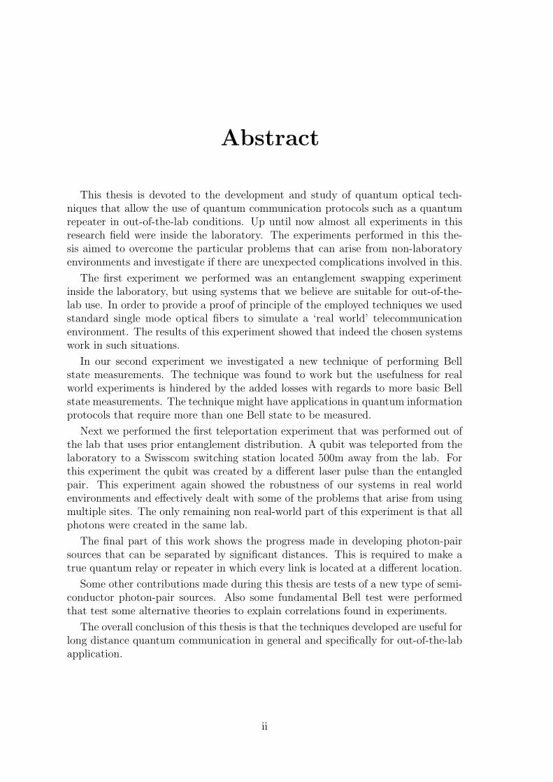
Figure 2.4: It is possible to extend time-bin encoding to higher dimensions. In thiscase the variable coupler is a d-to-d coupler and the switch a d-to-1 switch.
As indicated in the beginning of this section, this encoding scheme is much eas-ier to stabilize, there are two experimental constraints. First of all a stabilizationof the path length difference τc. This is required in order to have a well definedqubit. Secondly a stability of the transmission fiber on timescales of the order ofτ is required in order not to alter the qubit during transmission. The last require-ment is automatically satisfied for ns-scale delays whereas the first requirement isexperimentally feasible. This encoding scheme is called time-bin encoding[24]. Forsimplicity we will often use “a time-bin qubit” or simply “qubit” when we mean “aphoton encoded with a time-bin qubit”.
Analysis of time-bin qubits can be done as follows. If it is desired to project thestate on |0〉 or |1〉 it is sufficient to determine the time of arrival relative to the timeof emission of the photon. For a more general projection it is possible to do theinverse of the time-bin creation. First the qubit will pass through a switch followedby path length difference identical to the one used in the creation of the qubit. Atthis point the photon arrives at a coupler in a superposition of being in one inputport or the other. The output port of the photon will then be determined by thephase difference of the encoding and decoding paths. This method determines thephase of the qubit.
Unfortunately the time-bin scheme is not technologically feasible when τ is small(order of a ns). The above mentioned low-loss fast optical switches required in orderto create and analyze the qubits don’t exist yet. An alternative is to use a 50/50coupler. This means that half of the time the photon will exit through the wrongport and will be lost. When this technique is used the encoding device correspondsto an unbalanced interferometer. All experiments in this thesis use this technique.
At this point it is interesting to note another difference between polarization en-coding and both time-bin encoding and dual-rail encoding. It is possible to extendthe time-bin or dual-rail scheme to multiple dimensions ie. create d-dimensionalqudits[25, 26] This can be done by using multi channel couplers and switches andhaving d different possible time delays (Fig. 2.4) for the time-bin scheme or d dif-ferent paths for the dual-rail system. Polarization encoding is limited to the twopolarization modes, and can therefore only be used for 2-dimensional qubits.
For the experiments done in this thesis all qubit encoding was done using time-bins created with the described interferometer techniques. Technical details will be
9
VC SW
dl
dlVC PM=
high birefringance material
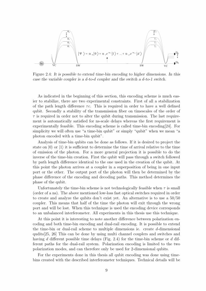
Figure 2.5: It is possible to create time-bin qubits based on spatial mode dispersionor polarization mode dispersion. The two resulting qubits are completely equivalent.PM is a polarization modulator.
discussed later in this thesis.
2.1.3 Alternative time-bin creation
The relation between time-bin encoding and spatial mode encoding is very clear.Time-bin encoding is a truncated version of spatial mode encoding. Since thereis also a large similarity between polarization encoding and spatial mode encodingit is interesting to consider if it is possible to also make a truncated version ofpolarization-encoding?
It is possible to transform a polarization qubit into a spatial mode qubit byseparating the polarizations on a polarizing beamsplitter. It is then possible toproceed as above to construct a time-bin qubit. This method has no experimentaladvantages over directly creating spatial mode qubits since the requirements arebasically the same. Another alternative would be to directly go from polarizationto time-bin (Fig. 2.5). This can be achieved with a large delay which is generatedbetween both polarization modes while they are in the same spatial mode. This can,for example, be done with high-birefringence (hibi) materials. After a certain lengthof such hibi-material the two polarization modes are well separated in time/space.The final step is to put both polarization modes into the same mode. This caneither be done by a fast polarization modulator in analogy with a fast switch, or byhaving a PBS at 45 degrees with respect to the qubit encoding axes. In this last casethe two exit ports are equivalent to the two exit ports of the time-bin generatingunbalanced interferometer. This method for generating time-bin qubits hasn’t beenexperimentally investigated to our knowledge because it requires large amounts ofexpensive hibi-materials, but if higher birefringence materials can be found it willbe interesting to see if it is not experimentally more convenient.
10
Chapter 3
Photon-pair sources and singlephotons
3.1 Introduction
In the previous chapters it was assumed that it is possible to create and to manip-ulate single photons and photon pairs. Since such sources will be extensively usedlater in this thesis an explanation of their functioning will be given is this chapter.
Naively one would think that it is easy to create a photon. Just think of a humblelight-bulb, it easily generates 1018 photons per s (assuming 50W with 1% efficiencyand only 400nm photons), so how hard can it be to create one photon? It turnsout that, although it is easy to create a photon, it is a lot more difficult to create asingle specific photon at a specific time.
The important parameters for both single photon sources and photon pair sourcesare:
1. Output rate
2. Collection efficiency and internal losses
3. Wavelength and tunability
4. Bandwidth of created photons
5. Statistics
The importance of the first parameter is obvious. Since high transfer rates are com-monplace in modern telecommunication, QC applications also require reasonablyhigh rates in order to be useful. Transfer rates are in practice often limited bytransmission and detection losses. However, it is not the case that the output rateshould be as high as possible in order to compensate. Currently sources are mainlyprobabilistic sources, and for protocols such as quantum teleportation to functionthe probability of emitting more than one photon(-pair) needs to be kept small.
The second parameter is of importance mainly in photon-pair sources, in single-photon sources a low collection efficiency can, in principle, be compensated by higher
11
output rates. In photon-pair sources, however, it is important that whenever onephoton is collected that there is a large probability of collecting the second photonof the same pair, and that this probability is higher than the possibility of collectinga photon from another pair.
The wavelength (point three) is obviously of importance because all manipula-tions depend on the wavelength and tunability is important because in many QCprotocols it is important to create photons with the same wavelength in differentsources. For experiments that use standard fiber optics the wavelengths with low-est losses are around 1.5µm . Also wavelengths around 1.3µm have low losses andfurthermore have zero dispersion.
The bandwidth and coherence length are important mainly in experiments thataim to use indistinguishable photons. For the case of gaussian pulseshapes thecoherence length lc is linked to the bandwidth as follows:
lc =2ln2
π
λ2
∆λ(3.1)
In the QC protocols used for this thesis it is important that photons arrive ‘atthe same time’. This means that the photons should arrive within their coherencelengths. In order to make this experimentally feasible large coherence lengths areuseful, and thus smaller bandwidths are desirable.
Finally the statistics of the source are important. In other words the g(2)(0) = 2p2
p21
parameter should be as low as possible. pi is the probability to create i pairs or singlephotons at the same time. An ideal source has g(2)(0) = 0.
3.2 Single photon sources
The techniques used for single-photon sources have seen a lot of development re-cently. Some of the designs involve quantum dots[27], vacancy centers in diamond[28]and heralding from frequency conversion photon-pair sources. In this thesis the lasttechnique will be used. It consists of using a photon-pair source (see section 3.3)and a single photon detector. Assuming that both photons from the pair are notidentical, in our case because of different wavelengths, it is possible to determin-istically separate them. After this separation one of the two photons is sent to adetector. If the detector finds a photon it is known the other photon was created aswell and the detector sends out a heralding signal (Fig. 3.1). Note that although itis certain that both photons are always created as a pair, it is not guaranteed thatboth photons will be collected.
Another type of single photon source used in this thesis is a photon-pair sourcefrom which a single photon is discarded without detection. Such a source has ahigher output rate than a heralded source but it has more noise. However the g(2)(0)parameter of such a source (g(2)(0) = 2) is worse than that of a attenuated laser(g(2)(0) = 1), it should therefore be considered as a pseudo-single photon source.
12

hu
huhu huhu
hu Electronic heralding signal
Single photon output
huhuWDM
Figure 3.1: Schematic of a heralded photon source. A pair of non-degenerate photonsis used as the input. WDM is a wavelength division multiplexer.
hn
hn
2
hn
2
Figure 3.2: A single photon send into a medium with a large non-linear coefficientχ(2) has a probability p to be converted into two lower energy photons.
3.3 Photon-pair sources
The most commonly used technique for photon-pair creation is spontaneous para-metric downconversion (SPDC)[29]. Other, less used, techniques will be brieflyreviewed at the end of this chapter.
3.3.1 Spontaneous parametric downconversion
Non-linear effects can happen in media with a strong non-linear coefficient χ(n), n >1. Non-linear in this case relates to the non-linear response of the polarization P ofa media to the electric field E of light. The dielectric polarization can be written asfollows:
P (t) ∝ χ(1)E(t) + χ(2)E2(t) + χ(3)E3(t) + etc. (3.2)
Effects caused by higher order terms are normally not visible because they occurwith extremely low probability. χ(2) is zero in centro-symmetrical systems such asa standard optical fiber but in certain materials they can be large enough to seeeffects, such as in Lithium Borate (LBO) crystals. A large χ(2) results in three-wavemixing effects, such as spontaneous parametric downconversion (SPDC) or secondharmonic generation (SHG)
In SPDC a single photon is transformed into a pair of photons (Fig. 3.2) througha non-linear interaction with the medium. Energy and momentum conservation leadto the following constraints on this process:
ωp = ωs + ωi (3.3)
~kp = ~ki + ~ks (3.4)
here ωj is the frequency and ~kj the wavevector. The subscripts p, s and i stand forpump, signal and idler respectively.
In order to adhere to the first constraint the created photons must have frequen-cies symmetrically located around half the pump frequency.
13
The second constraint is more demanding, since the medium in which the SPDCoccurs has chromatic dispersion the velocities of all components of the SPDC are notequal. This leads to a dephasing of pump-photons and signal/idler-photons whichin turn leads to destructive interference. There are two practical solutions to thisproblem.
The first solution is so-called phasematching by birefringence. By using a materialwhich has a large difference in refractive index as a function of the polarizationit is possible to achieve a situation in which the pump-photons and the createdphotons travel at the same speed (ie. their phase will remain matched). This typeof phase matching is limited to certain wavelengths depending on the refractiveindex n. A method to tune which wavelengths can be generated is changing thetemperature and thus the phase-matching conditions. Materials which are suitedfor such techniques are for example LBO, beta-Barium Borate (BBO) and PotassiumTitanium Phosphate (KTP).
The second solution is quasi phase-matching. This solution requires a materialin which χ(2) changes its sign periodically. In such a material the phase-matching issuch that the photons are never interfering destructively but there is always (non-optimal) constructive interference. In this case the requirement 3.4 is changed to:
~kp = ~ki + ~ks + ~K (3.5)
| ~K| =2π
Λ(3.6)
here Λ is the poling period. Materials using this type of phase matching are re-ferred to as periodically poled (PP), for example PP Lithium Niobate(PPLN) orPPKTP. Quasi phasematching has the advantage over birefringence phasematchingthat is possible to create a very large range of wavelengths since there is a differentparameter that can be changed. Futhermore it allows the use of higher non-linearcoefficients.
The overall efficiency of the SPDC process is determined by the χ(2) parameter ofthe non-linear medium and the interaction length. The efficiency is thus limited bythe choice of material and in that respect it cannot be easily increased. One methodthat can be used to increase overall conversion is to use a longer non-linear medium.An increase of the power density can be accomplished by using waveguide structuresto confine the light. The use of waveguides with birefringent phasematching iscomplicated by the polarization requirements of the guide. However it is possibleto create waveguides in PP-materials, for example by using soft-proton exchangetechniques in order not to affect to the periodical poling[30].
3.3.2 Alternative sources
Besides SPDC several other types of photon-pair sources exist. Not all of them willbe discussed here but some of the better known sources will be briefly explained.
One promising type of source of telecommunication wavelength photon-pairs uses4-wave mixing[31]. The process used is similar to SPDC but it uses two pump-photons to generate a pair.
ωp1 + ωp2 = ωs + ωi (3.7)
14

Figure 3.3: The use of waveguides allows for a better collection of the generatedphoton-pairs. Because of the waveguide the length doesn’t influence the collectionefficiency.
The efficiency of this process is determined by χ(3). The main advantage of such asource is that it is possible to use optical fibers as non-linear medium, therefore cou-pling to the fiber should be near perfect. Phasematching is possible for frequenciesnear the pump frequencies when using the fiber around its zero-dispersion frequencyleading to the disadvantage that a very efficient filtering system is required to filterthe large amount of pump photons from the generated photon-pairs. At the momentsuch sources don’t reach their full potential since the filtering system is not fiberedand therefore the main advantage is negated.
Another type of source are quantum dot(QD)[27]. A QD is a nanostrucutre in asemi-conductor which restricts the free electron-holes. This can create a situationin which an excited electron-hole pair releases its energy in the form of a pair ofphotons. This technique works but it is difficult to get a good collection efficiencyfrom a QD, progress in this field is made by trying to create micro cavities arounda QD.
As part of this thesis a collaboration with the group of G. Leo in Paris for aphoton-pair source based on SPDC in semiconductor waveguides was performed. Ashort description of this experiment will be given in section 10.1
3.3.3 Frequency upconversion
SPDC is closely related to another frequency conversion technique: frequency up-conversion. In this case the process is exactly the opposite of the process describedabove. Two photons with frequency ω1 and ω2 are transformed into one photon withfrequency ω3 = ω1 + ω2. Phasematching is created by using the same techniquesas before. This process can for example be used for information transfer from one
15
wavelength to another[32]. Later in this thesis it will be used to create a brightsource of pulsed light that cannot be easily made without such a technique.
16

Chapter 4
Single Photon Detection
4.1 Introduction
So far we have discussed the creation of single photons or pairs of photons that canbe used in a multitude of QI and QC protocols. All such protocols require detectionof the photons either to obtain the result or as a part of the protocol. Unfortunatelythis is not a trivial task, especially for low energy photons such as photons at telecomwavelengths.
For our purposes there are several important parameters for photon detectors:
1. Detection efficiency
2. Dark count probability
3. Duty cycle
4. Maximum countrate
5. Temporal resolution
The detection efficiency η is defined as the probability for the detector to clickwhen a single photon arrives. Most detector research focusses on this crucial param-eter. For avalanche photodetectors (see the next section) efficiency can be changedby varying the bias voltage of the device. However an increase in η generally alsomeans an increase in the dark count probability PDC which is defined as the proba-bility per ns of having a click when there is no photon present. In such detectors acompromise between η and PDC must be reached. In general it is important to findan optimal signal to noise ratio (SNR).
The duty cycle of a detector is important in order to make optimal use of thedetector. Not all situations are limited by a duty cycle as will be shown later.The maximum countrate is important as well for high bit rate experiments. In mostprotocols using the detector too close to the maximum countrate (saturation) resultsin a large reduction of the output rate. This is caused by the deadtime (explainedlater) which reduces the duty cycle.
17
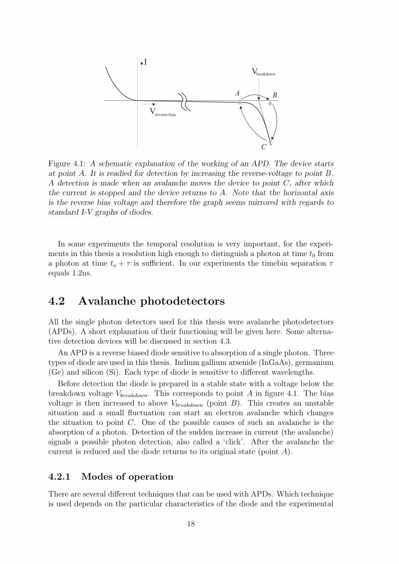
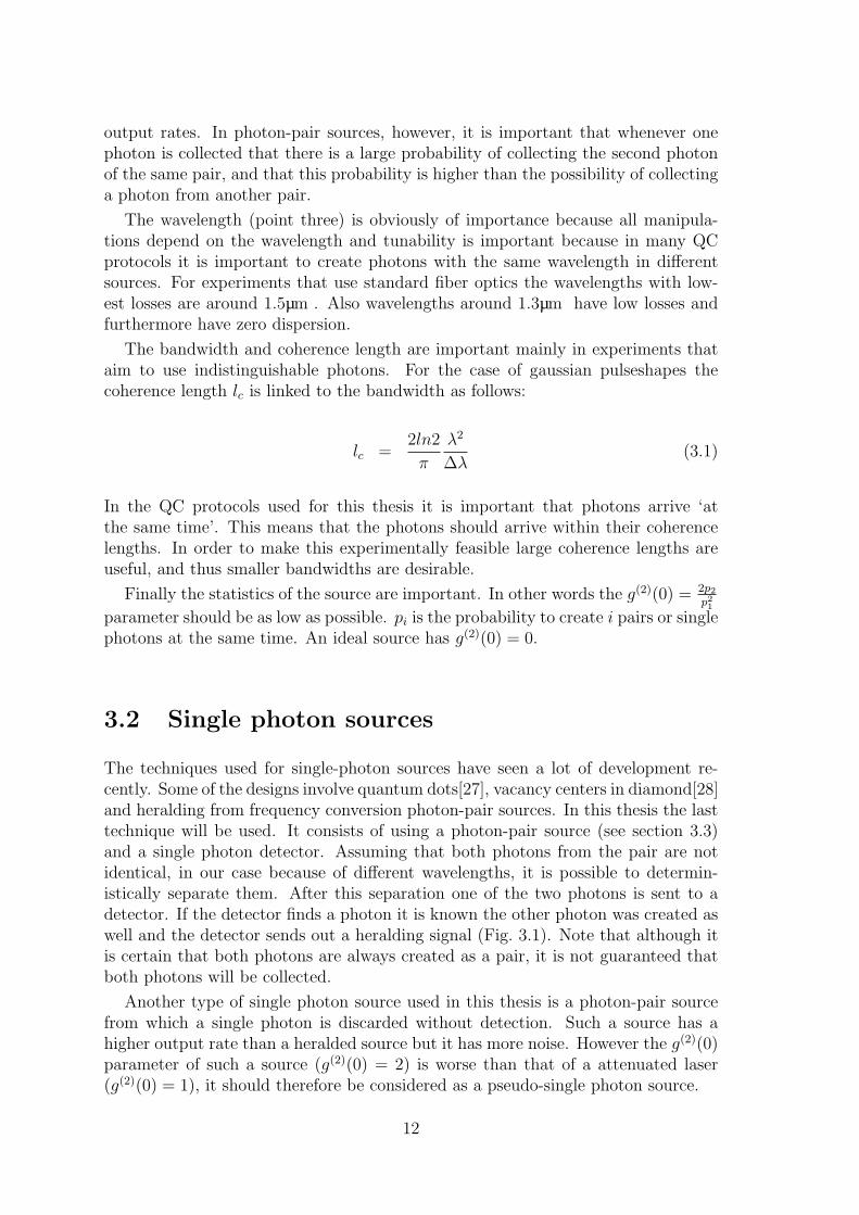
Vbreakdown
A B
C
V
I
reverse-bias
Figure 4.1: A schematic explanation of the working of an APD. The device startsat point A. It is readied for detection by increasing the reverse-voltage to point B.A detection is made when an avalanche moves the device to point C, after whichthe current is stopped and the device returns to A. Note that the horizontal axisis the reverse bias voltage and therefore the graph seems mirrored with regards tostandard I-V graphs of diodes.
In some experiments the temporal resolution is very important, for the experi-ments in this thesis a resolution high enough to distinguish a photon at time t0 froma photon at time to + τ is sufficient. In our experiments the timebin separation τequals 1.2ns.
4.2 Avalanche photodetectors
All the single photon detectors used for this thesis were avalanche photodetectors(APDs). A short explanation of their functioning will be given here. Some alterna-tive detection devices will be discussed in section 4.3.
An APD is a reverse biased diode sensitive to absorption of a single photon. Threetypes of diode are used in this thesis. Indium gallium arsenide (InGaAs), germanium(Ge) and silicon (Si). Each type of diode is sensitive to different wavelengths.
Before detection the diode is prepared in a stable state with a voltage below thebreakdown voltage Vbreakdown. This corresponds to point A in figure 4.1. The biasvoltage is then increased to above Vbreakdown (point B). This creates an unstablesituation and a small fluctuation can start an electron avalanche which changesthe situation to point C. One of the possible causes of such an avalanche is theabsorption of a photon. Detection of the sudden increase in current (the avalanche)signals a possible photon detection, also called a ‘click’. After the avalanche thecurrent is reduced and the diode returns to its original state (point A).
4.2.1 Modes of operation
There are several different techniques that can be used with APDs. Which techniqueis used depends on the particular characteristics of the diode and the experimental
18

R
Vbias
t
I
Output signal
Vbias
I
Output signal
quench
Vbias
I
Output signal
Fee
dbac
k
Figure 4.2: Different methods can be used to stop the current flowing through anAPD after it has passed its breakdown voltage. On the left the scheme for shortpulse gated mode operation is shown, in the middle passive quenching and on theright active quenching.
requirements. The techniques can be roughly separated in the following two groups.
The first group we will call ‘gated mode operation’ (GMO) also known as ‘trig-gered detectors’. It is possible to ready the detector (point B)for detection duringa time Tgate after which the bias voltage is reduced to below Vbreakdown (point A)regardless of photon detection. An important consequence of this form of biasingis that it is required to tell the detector when to expect a photon. In experimentswhere this is approximately known this technique can be very useful since it permitsa reduction of the number of darkcounts.
The second group of techniques is ‘freerunning operation’ (FO) also called ‘passivedetectors’. In this case the bias voltage is almost always kept high (position B), andis only reduced after detection. This technique doesn’t require any knowledge aboutthe approximate arrival time of the photons. If the arrival time of the photons isnot known but FO is not possible GMO detectors can be used with random triggers.This technique simulates a FO detector with a GMO detector. The disadvantage isthat often the detector will not be ready for a photon and the resulting duty cycleeffectively reduces the efficiency. When using a large amount of short gates thistechnique is also known as rapid gating.
For both groups it is important to stop the current through the diode as soon aspossible after a detection. This is known as ‘quenching’. If GMO is used with shortgates (typically of the order of a few ns) quenching is not required since the currentis stopped at the end of the gate. In all other cases quenching is required mainlyin order to protect the diodes but also to reduce noise. There are two differentpossibilities for quenching, active or passive quenching (Fig. 4.2).
For passive quenching it is sufficient to add a resistance to the circuit. As soonas a current starts to flow the increased voltage loss over the resistance will resultin an effective reduction of the bias voltage. Once the diode is sufficiently backbelow breakdown the current stops and the original situation (point A) is restored.This method of quenching has the advantage that it is very easy to implement and
19
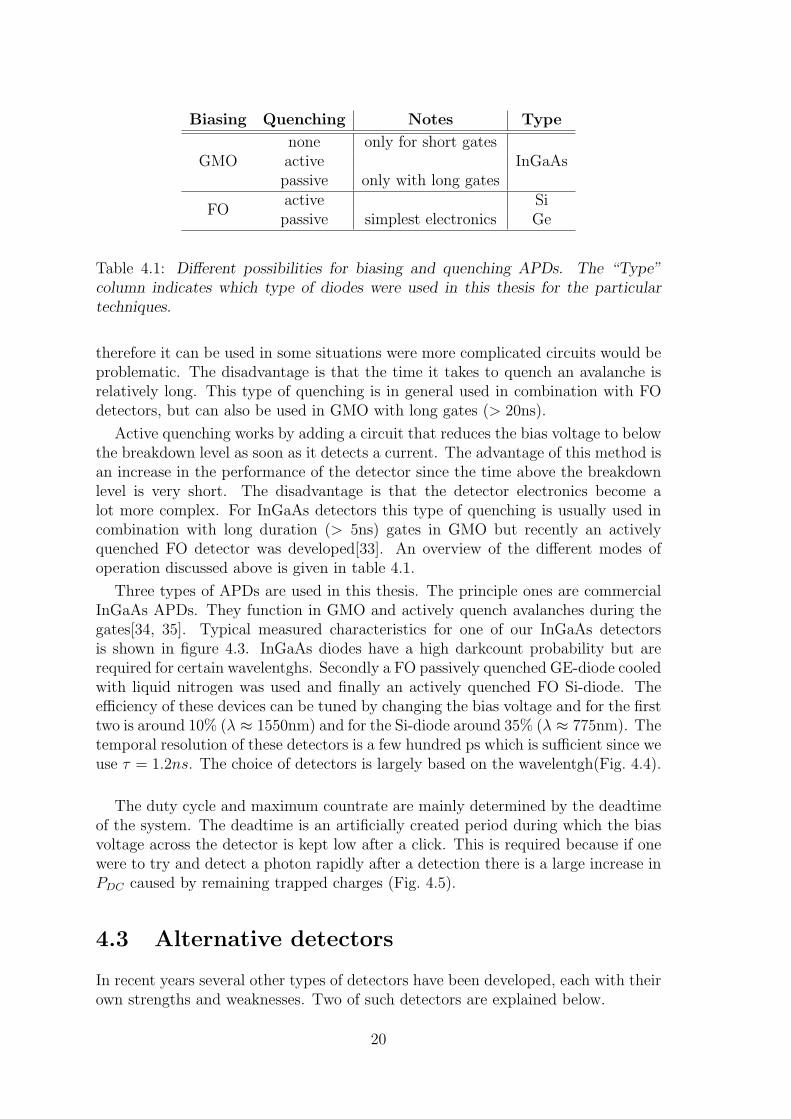
Biasing Quenching Notes Type
GMOnone only for short gatesactive InGaAspassive only with long gates
FOactive Sipassive simplest electronics Ge
Table 4.1: Different possibilities for biasing and quenching APDs. The “Type”column indicates which type of diodes were used in this thesis for the particulartechniques.
therefore it can be used in some situations were more complicated circuits would beproblematic. The disadvantage is that the time it takes to quench an avalanche isrelatively long. This type of quenching is in general used in combination with FOdetectors, but can also be used in GMO with long gates (> 20ns).
Active quenching works by adding a circuit that reduces the bias voltage to belowthe breakdown level as soon as it detects a current. The advantage of this method isan increase in the performance of the detector since the time above the breakdownlevel is very short. The disadvantage is that the detector electronics become alot more complex. For InGaAs detectors this type of quenching is usually used incombination with long duration (> 5ns) gates in GMO but recently an activelyquenched FO detector was developed[33]. An overview of the different modes ofoperation discussed above is given in table 4.1.
Three types of APDs are used in this thesis. The principle ones are commercialInGaAs APDs. They function in GMO and actively quench avalanches during thegates[34, 35]. Typical measured characteristics for one of our InGaAs detectorsis shown in figure 4.3. InGaAs diodes have a high darkcount probability but arerequired for certain wavelentghs. Secondly a FO passively quenched GE-diode cooledwith liquid nitrogen was used and finally an actively quenched FO Si-diode. Theefficiency of these devices can be tuned by changing the bias voltage and for the firsttwo is around 10% (λ ≈ 1550nm) and for the Si-diode around 35% (λ ≈ 775nm). Thetemporal resolution of these detectors is a few hundred ps which is sufficient since weuse τ = 1.2ns. The choice of detectors is largely based on the wavelentgh(Fig. 4.4).
The duty cycle and maximum countrate are mainly determined by the deadtimeof the system. The deadtime is an artificially created period during which the biasvoltage across the detector is kept low after a click. This is required because if onewere to try and detect a photon rapidly after a detection there is a large increase inPDC caused by remaining trapped charges (Fig. 4.5).
4.3 Alternative detectors
In recent years several other types of detectors have been developed, each with theirown strengths and weaknesses. Two of such detectors are explained below.
20

0.05 0.10 0.15 0.20 0.25 0.30 0.35 0.40 0.451E-7
1E-6
1E-5
1E-4
1E-3
0.01
0.1
Dar
k co
unt r
ate
(per
ns)
Detection efficiency
Figure 4.3: A typical relation between the efficiency of a APD and the dark countrate. Note the logarithmic scale which means that a small increase in efficiency isaccompanied by a large increase in noise
l(nm)0
Si
1000 2000
Ge
InGaAs
Figure 4.4: Illstration of the working range of different types of APD. The workingrange highly depends on the fabrication process and requirements of the diodes.
0 5 10 15 20 25 301E-4
1E-3
0.01
0.1
Pro
babi
lity
to fi
nd a
dar
k co
unt (
per g
ate)
Time after detection ( s)
Figure 4.5: Probability of detection a darkcount shortly after a detection.
21

NLC
Filter
Si-APD
w1
w2
w3
Figure 4.6: Scheme of an upconversion based single photon detector at telecommu-nication wavelengths. First the input photon is converted with an auxiliary photonto a photon with a different wavelength in a non-linear cryptal(NLC). This photonis then efficiently detected by a Si-APD.
Detection after upconversion
One alternative detection technique for measuring single photons at telecommuni-cation wavelengths is to convert the photon to be detected to another wavelength inwhich good APDs exist. For telecommunication wavelengths such a detector consistsof an upconversion of the photon at ω1 combined with a photon from an auxiliarysource ω2 to a photon with ω3 = ω1 + ω2, followed by the detection of this photonwith an Si-APD[36]. Efficiencies up to 5% have been reached but the dark countprobability is relatively high with 10−4 dark counts per ns. This detector techniquehas the advantage that it has low jitter (50 ps) if a low jitter Si APD is used.
Superconduction meanders
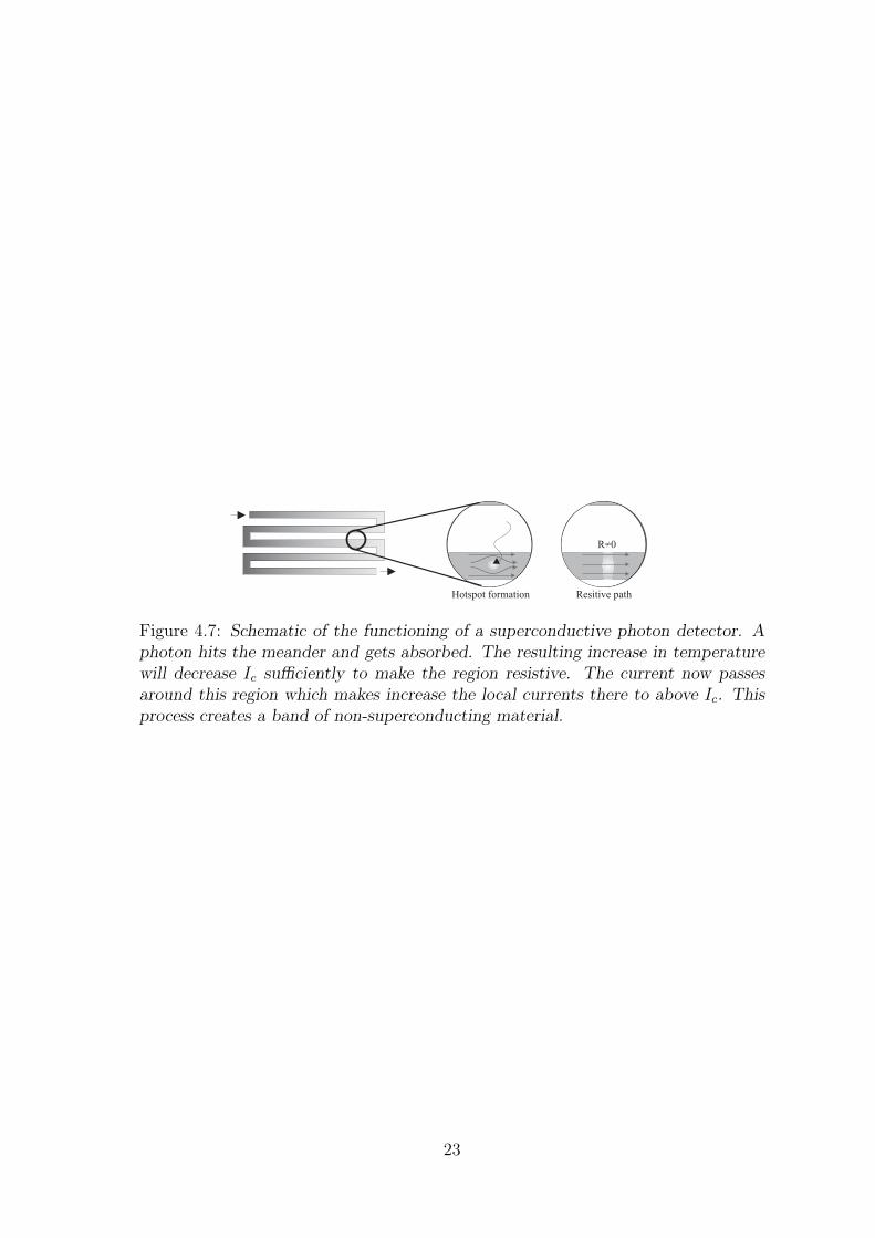
Another technique for single photon detection involves specially structured super-conductors [37]. Typically a thin film of superconducting material is deposited ona substrate. A meandering structure is created using etching techniques. A currentslightly below the critical current Ic is passed through this structure. If a photon hitsthe meander this will heat up a small region, which causes a reduction of Ic. If thisdrop is large enough the current in the meander will be larger then the critical cur-rent and therefore a small non-superconducting region will be created. The currentwill avoid this area and therefore the surrounding areas will have a current increase.Since the current was close to Ic such an increase will in turn cause those areas tostop being superconductive. This process creates a “band” of non-superconductivematerial which means that the device now has a detectable resistance.
A measured change of the resistance of such a detector equals a ‘click’ of anAPD. After a detection it suffices to reduce the current in order to make the wholesystem superconducting again and the whole cycle can start over. A disadvantage isthat the detectors require a cryostat in order to reach superconductivity (typicallywith temperatures of a few Kelvin) but it the has advantage that it has a low darkcount rate. Furthermore it has been suggested that such detectors might be able todistinguish between a single or multiple photons[38, 39]. Finally the detectors canbe used as passive detectors which is very useful for many protocols.
22
Hotspot formation Resitive path
R=0
Figure 4.7: Schematic of the functioning of a superconductive photon detector. Aphoton hits the meander and gets absorbed. The resulting increase in temperaturewill decrease Ic sufficiently to make the region resistive. The current now passesaround this region which makes increase the local currents there to above Ic. Thisprocess creates a band of non-superconducting material.
23


25
Chapter 5
Entanglement
If the differences between a quantum world and a classical world had to be definedby a single property it would probably be entanglement. Entanglement describesproperties of multiple distinct systems which cannot be properly described for eachsystem individually. The results of entanglement can be completely counterintuitiveand very different from what can be predicted with classical theories. In order toexplain entanglement it is useful to directly consider one particular type of entan-glement, in our case time-bin entanglement[24].
5.1 Time-bin entanglement
Consider the following situation (Fig. 5.1). A bright laser pulse is send throughan unbalanced interferometer. After the interferometer there are two pulses with afixed phase relation between the two:
|α〉p → |α2〉0|eiφ α
2〉1
(5.1)
where we assumed 50/50 couplers and we ignored the second output port. Thesubscript p stands for pump and ‘0’,‘1’ indicate the temporal mode t0(t1). The
j
c (2) hu
hu
hu
hu
1100ji
ebea +=Y
)()( taaa j -+=Y tbetai
p
Figure 5.1: Experimental setup to create time-bin entangled qubits. An intenselaser pulse is send through an unbalanced interferometer. One of the outputs issend through a NLC in which a SPDC process can occur. The pump-photons arethen filtered out and the remaining photons are entangled photon-pairs.

pulses after the interferometer are send through a non-linear medium. At this pointthere is a certain probability that a SPDC process occurs: i.e. a single photon istransformed into a pair of photons as discussed in section 3.2.
(b†0c
†0a0 + b†1c
†1a1
)| α√
2〉0| eiφα√
2〉1|vac〉si → c(α)
(b†0c
†0 + eiφb†1c
†1
)| α√
2〉0| eiφα√
2〉1|vac〉si
The operators aj,b†j,c
†j stand for the creation operators of the pump, signal and idler
photons respectively. The subscript j = 0, 1 again indicate temporal mode and c(α)is the amplitude with which the process occurs.
The pump photons are at more or less half the wavelength of the generated pho-tons making it easy to remove the pump-photons with either a filter or a wavelengthdivision multiplexer(WDM). The remaining photons are in an entangled state:
(b†0c
†0 + eiφb†1c
†1
)|vac〉si = |0, 0〉si + eiφ|1, 1〉si (5.2)
Let’s look at some of the properties of such a state. If one of the two photonsis measured at time t0(t1), this collapses the overall state onto a state where bothphotons exist at time t0(t1) albeit that one of them was destroyed during measure-ment. For example measuring photon A at time t0 makes a projection of the stateΨ onto this result, the state |1, 1〉si is therefore eliminated the state of the secondphoton is also completely determined. In other words, if both photons are measuredthere will always be a perfect correlation between the measurement times. Look-ing at each photon individually however the results cannot be predicted and areprobabilistically determined.
5.1.1 Bell-states
For two qubits it is possible to construct a complete orthonormal basis using fourmaximally entangled states. These states are called the ‘Bell-states’:
|φ±〉 =1√2
(|0, 0〉ab ± |1, 1〉ab) (5.3)
|ψ±〉 =1√2
(|1, 0〉ab ± |0, 1〉ab) (5.4)
Since these states are a complete basis for two-qubit states it is also possible todescribe non-entangled or partially entangled states using the Bell-states. For thestates |ψ±〉 there is complete anti-correlation when detecting the photons instead ofthe correlation as was shown in the last paragraph.
5.2 Other types of entanglement
As seen above the defining property of entanglement is inseparability. This canbe achieved with time-bins but many other forms of entanglement exist. Probablythe most commonly investigated type of entanglement is polarization entanglement,
26
hu
110 0ji
eret +=Y
A1
A-1
B1
B-1
hu
no exclusion possibleexcludes
LHVT
excludes
LHVT & QM
S=1 S=4S=2 S=2 2Ö
a b
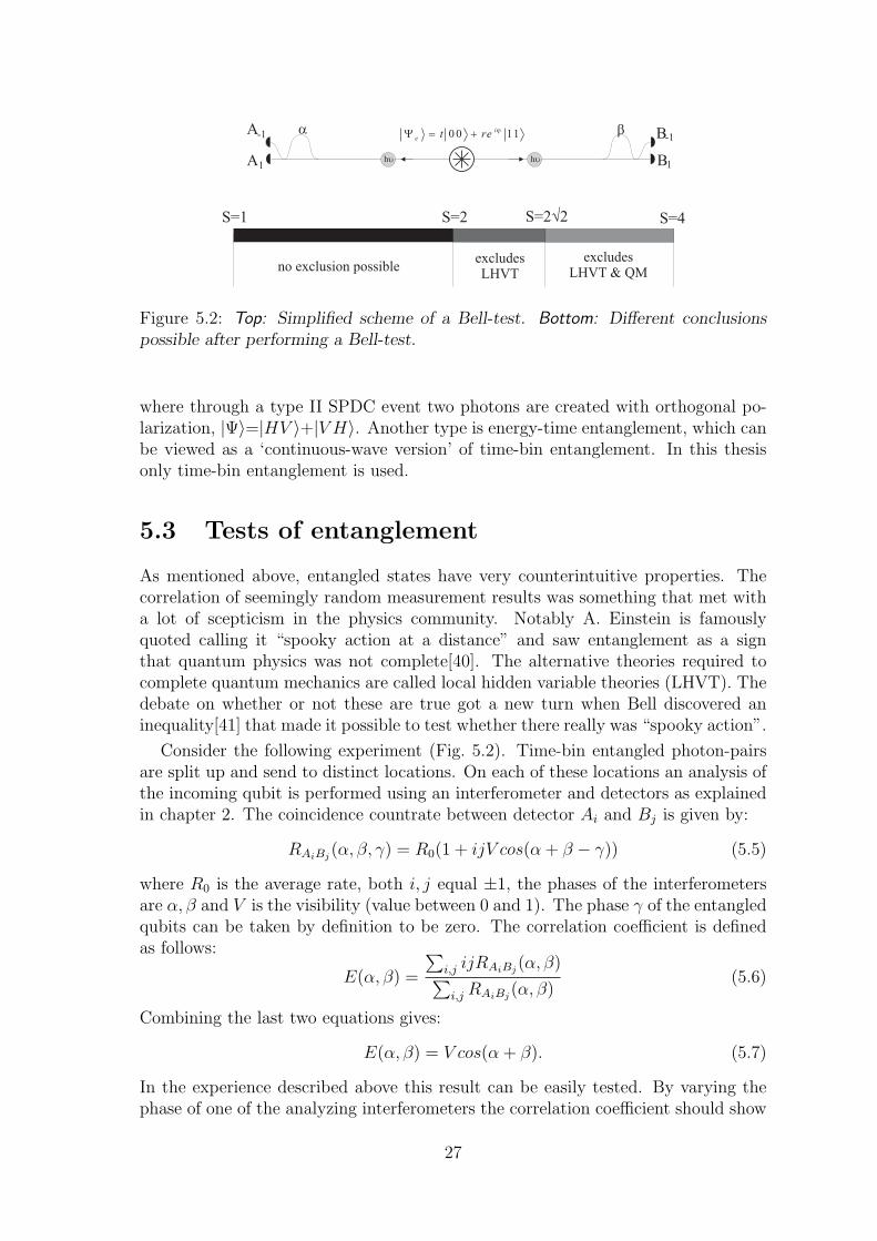
Figure 5.2: Top: Simplified scheme of a Bell-test. Bottom: Different conclusionspossible after performing a Bell-test.
where through a type II SPDC event two photons are created with orthogonal po-larization, |Ψ〉=|HV 〉+|V H〉. Another type is energy-time entanglement, which canbe viewed as a ‘continuous-wave version’ of time-bin entanglement. In this thesisonly time-bin entanglement is used.
5.3 Tests of entanglement
As mentioned above, entangled states have very counterintuitive properties. Thecorrelation of seemingly random measurement results was something that met witha lot of scepticism in the physics community. Notably A. Einstein is famouslyquoted calling it “spooky action at a distance” and saw entanglement as a signthat quantum physics was not complete[40]. The alternative theories required tocomplete quantum mechanics are called local hidden variable theories (LHVT). Thedebate on whether or not these are true got a new turn when Bell discovered aninequality[41] that made it possible to test whether there really was “spooky action”.
Consider the following experiment (Fig. 5.2). Time-bin entangled photon-pairsare split up and send to distinct locations. On each of these locations an analysis ofthe incoming qubit is performed using an interferometer and detectors as explainedin chapter 2. The coincidence countrate between detector Ai and Bj is given by:
RAiBj(α, β, γ) = R0(1 + ijV cos(α + β − γ)) (5.5)
where R0 is the average rate, both i, j equal ±1, the phases of the interferometersare α, β and V is the visibility (value between 0 and 1). The phase γ of the entangledqubits can be taken by definition to be zero. The correlation coefficient is definedas follows:
E(α, β) =
∑i,j ijRAiBj
(α, β)∑i,j RAiBj
(α, β)(5.6)
Combining the last two equations gives:
E(α, β) = V cos(α + β). (5.7)
In the experience described above this result can be easily tested. By varying thephase of one of the analyzing interferometers the correlation coefficient should show
27
700 800 900
0
50
100
150
200
250
300
Coi
ncid
ance
s (p
er s
)
Phase (arb. units)
noise level
Figure 5.3: A typical result for a Bell-test with time-bins. The fit shows Vnet =0.94± 0.01
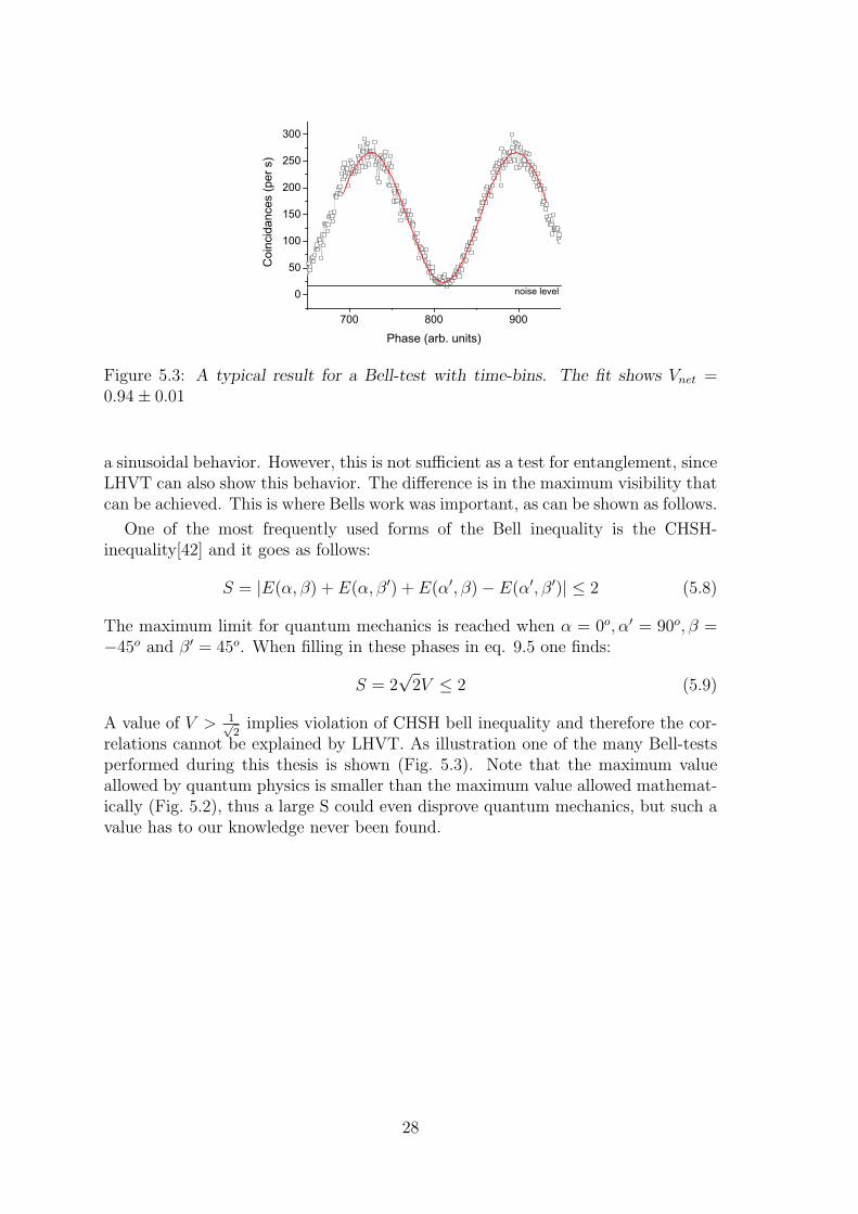
a sinusoidal behavior. However, this is not sufficient as a test for entanglement, sinceLHVT can also show this behavior. The difference is in the maximum visibility thatcan be achieved. This is where Bells work was important, as can be shown as follows.
One of the most frequently used forms of the Bell inequality is the CHSH-inequality[42] and it goes as follows:
S = |E(α, β) + E(α, β′) + E(α′, β)− E(α′, β′)| ≤ 2 (5.8)
The maximum limit for quantum mechanics is reached when α = 0o, α′ = 90o, β =−45o and β′ = 45o. When filling in these phases in eq. 9.5 one finds:
S = 2√
2V ≤ 2 (5.9)
A value of V > 1√2
implies violation of CHSH bell inequality and therefore the cor-relations cannot be explained by LHVT. As illustration one of the many Bell-testsperformed during this thesis is shown (Fig. 5.3). Note that the maximum valueallowed by quantum physics is smaller than the maximum value allowed mathemat-ically (Fig. 5.2), thus a large S could even disprove quantum mechanics, but such avalue has to our knowledge never been found.
28
Chapter 6
Long distance entanglementswapping [A]
6.1 Introduction
In the previous chapters a lot of the basic tools for QI and QC have been dis-cussed. In the following chapters some experiments will be described that use thesetechniques.
Entanglement swapping, also known as teleportation of entanglement, is a proto-col in which two entangled pairs “swap” the entanglement between their constituentparts. This creates the counterintuitive situation in which qubits can be entangledwithout having had a common past. The general scheme (Fig. 6.1) shows how thisis done: first two entangled photon-pairs are created, one part of each pair is send toa Bell-state analyzer (BSA) where a Bell-state measurement (BSM) is performed onthese photons. After a successful BSM the remaining photons are entangled, eventhough they have no common history.
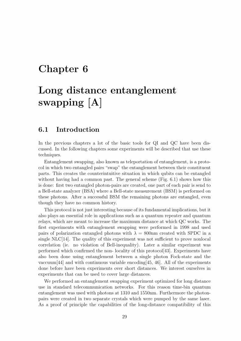
This protocol is not just interesting because of its fundamental implications, but italso plays an essential role in applications such as a quantum repeater and quantumrelays, which are meant to increase the maximum distance at which QC works. Thefirst experiments with entanglement swapping were performed in 1998 and usedpairs of polarization entangled photons with λ = 800nm created with SPDC in asingle NLC[14]. The quality of this experiment was not sufficient to prove nonlocalcorrelation (ie. no violation of Bell-inequality). Later a similar experiment wasperformed which confirmed the non- locality of this protocol[43]. Experiments havealso been done using entanglement between a single photon Fock-state and thevaccuum[44] and with continuous variable encoding[45, 46]. All of the experimentsdone before have been experiments over short distances. We interest ourselves inexperiments that can be used to cover large distances.
We performed an entanglement swapping experiment optimized for long distanceuse in standard telecommunication networks. For this reason time-bin quantumentanglement was used with photons at 1310 and 1550nm. Furthermore the photon-pairs were created in two separate crystals which were pumped by the same laser.As a proof of principle the capabilities of the long-distance compatibility of this
29

Bell state
analyzer
entangled photons
that never interacted
EPR source EPR source
a b c d
Figure 6.1: A scheme of the principle of entanglement swapping.
scheme were tested by adding additional fiber lengths to the experiment.
6.2 Entanglement swapping
Lets take a closer look at the entanglement swapping protocol. After the creation oftwo entangled pairs the overall quantum-state of the system is for example: |Ψ〉abcd =|φ+
δ 〉ab ⊗ |φ−δ 〉cd where |φ±δ 〉ab = 1√2
(|0, 0〉ab ± eiδ|1, 1〉ab
). The state |Ψ〉abcd can be
rewritten as follows:
|Ψ〉abcd = |φ+δ 〉ab ⊗ |φ−δ 〉cd (6.1)
=1
2(|φ+
δ 〉bc ⊗ |φ−2δ〉ad (6.2)
+|φ−δ 〉bc ⊗ |φ+2δ〉ad
+|ψ+δ 〉bc ⊗ eiδ|ψ−δ 〉ad
+|ψ−δ 〉bc ⊗ eiδ|ψ+δ 〉ad)
where |ψ±δ 〉ab = 1√2
(|0, 1〉ab ± eiδ|1, 0〉ab
). When a BSM is performed on photons b
and c the rest of the system is projected onto the result of this measurement andthus photons a and d end up in one of the Bell-states as well. If the BSM finds|ψ±δ 〉bc the remaining photons will be in the state |ψ∓δ 〉ad with a global phase factorδ hence this phase is not important for |ψ±δ 〉bc. For the other cases the state will bedependant on 2δ. This can be corrected with a unitary transformation for protocolsin which the same output state is required.
6.2.1 Experimental setup
The following experimental scheme was used (Fig. 6.2) to perform an entanglementswapping experiment. A mode-locked femto-second laser with λ = 710nm createspulses with a length of about 200fs. These pulses are sent into an unbalanced bulkMichelson-interferometer. The path length difference in this interferometer has been
30
Femto-second laser
lp=710 nm
LBO
SF
WDM
SF
WDM
Ge
C2
InGaAs
AB
InGaAs
LBO
Beam splitter 50:50
C1
InGaAs
1550 nm 1550 nm1310 nm 1310 nm
Charlie
BSM
Alice Bob
C D
a
FM
FM
b
FM
FM
d
1.1 km DSF1.1 km DSF
Pump
interferometer
Figure 6.2: A scheme of the experimental setup used to perform the entanglementswapping protocol.
31

pump
possible photons
pump
possible photons
Figure 6.3: If the coherence length of photons created with SPDC is smaller thanthe length of the pump pulse a distinguishability can arise. In this case the ‘dashed’photon is distinguishable from the ‘non-dashed’ photon.
tuned to τ = 1.2ns which corresponds to a path length difference of 18cm back andforth in air, or 12cm of standard optical fibers.
In our pump interferometer retro-reflectors are used which facilitate the use ofthe input port as an output port without requiring a circulator. Each of the outputsis sent to a separate Lithium-Triborate (LBO) non-linear crystal. SPDC createscollinear non-degenerate photon-pairs at telecommunication wavelengths (1310 and1550nm). At this point the overall state equals eq. 6.1: |Ψ〉abcd = |φ+
δ 〉ab ⊗ |φ−δ 〉cd.The difference between |φ+
δ 〉ab and |φ−δ 〉cd is a result of the different amount of re-flections in the interferometer. Note that the phase δ is automatically the same forboth pairs because of the use of a single pump interferometer.
The generated pairs are coupled into a single-mode fiber (SMF) where they areseparated using a wavelength division multiplexer (WDM). The photons at 1310nmare both sent to the BSA , which in this case is just a simple 50/50-coupler. Moreon the workings of this BSA in chapter 7.1. For the BSA to function it is requiredthat both incoming photons are completely indistinguishable in temporal, polariza-tion and spectral modes. This is verified by first performing a Hong-Ou-Mandeldip[47](HOM-dip) before the swapping experiment. This means scanning a variableoptical delay in order to minimize the amount of coincidences.
The photons at 1310nm are filtered with 5nm bandwidth interference filters inorder to increase their coherence time to 500fs and to assure that both have the samespectrum. It is required to have coherence lengths longer than the pulse length inorder to assure temporal indistinguishability (Fig. 6.3).
The remaining photons each travel through 1.1km of dispersion shifted fiber andare filtered with a 18nm bandwidth filter. This filtering is required in order not tosaturate the detectors with uncorrelated photons belonging to photon-pairs that donot pass the wavelength requirements of the 1310nm filter. The entanglement of thetwo remaining photons is analyzed by performing a Bell-test as explained in chapter5.3. For this purpose two fibred Michelson-interferometers with Faraday-mirrors areused. These mirrors have the advantage of automatically aligning the polarizationof the interferometers.
Since the experiment requires four-fold coincidences it takes a long time to finish ameasurement. It is required that the phases of the analyzing interferometers remainconstant during this time. This is guaranteed by having an active feedback systemthat probes the phase of the interferometers from time to time using a stabilized
32

Faraday
Mirrors
Fiber
around
Piezo
50/50
couplertemperature
controlled box
1510nm
WDM
PIN-diode
In & OutOut only
Figure 6.4: An interferometer controlled with an active feedback loop.
diode-laser at a different wavelength. Adjustments of the phase are possible sinceone of the arms in the interferometer is partially wrapped around a cylindrical piezo-actuator. When changing the voltage over this piezo the optical length of the fiberchanges and thus the phase of the interferometer (Fig. 6.4). The phase of the pump-interferometer is not stabilized in this experiment. This is not required since onlythe phase difference between the pairs plays a role. Since both pairs pass trough thesame interferometer this difference is stable (see eq. 6.2).
In this experiment there are three different interferometers, one pump interfer-ometer and two analyzing interferometers. It is important to align the lengths ofthe different interferometers with each other. In order to do this two preliminaryexperiments are performed. The first is a straightforward single photon interferenceexperiment. When putting both fiber interferometers in series and passing a photonthrough them it is possible to find an interference fringe. By changing the lengths ofthe fibers it is possible to optimize the visibility of this fringe and thereby aligningboth of the interferometers to within the coherence length of the photons. As a sec-ond step these interferometers need to be aligned with the bulk interferometer. Thisis done by performing and optimizing Bell-tests with an additional interferometerfor the 1310nm photons.
The photons are detected using APDs. One of the outputs of the 50/50-coupler issent to a Ge-diode cooled with liquid nitrogen and operated using passive quenching.It has an efficiency of around 10% for 40kHz of dark counts. The three other photonsare detected using commercial id-200[34] detectors which are triggered InGaAs APDswith an efficiency of around 30% and 10−4 darkcounts per ns of gate. The triggersignal of these detectors is given by an electronic coincidence between a detection ofthe Ge-APD and a reference signal from the mode-locked laser. This step eliminatesa large part of the noise of the passive detector. It is possible to do this since a pulsedsetup is used and therefore photons can only arrive at fixed times. The signals fromthe InGaAs detectors are sent to a multichannel time-to-digital converter (TDC)
33

100 200 300 400 500 600
0
10
20
30
40
50
60
70
80
90
100
Four-
photo
ncoin
cid
ences
[/6h]
Phase [degrees]
0
1000
2000
3000
4000
5000
3-p
hoto
ncoin
cid
ences
[/6h]
withoutB
SM
Figure 6.5: Result of the entanglement swapping experiment showing a visibilityV=80% .
which uses the trigger signal as a start and the detection signals as stops. Theresulting digital signals are analyzed by computer to find the number of coincidencesfor each setting of the interferometer phases.
6.2.2 Results and conclusions
In order to prove that conditionally on a successful BSA the photons a and d areentangled we scan the phase of one of the interferometers and record the coincidencecounts. In theory this should show a sinusoidal dependance on the phase
Rc = R0 (1 + V cos(α + β)) (6.3)
with a visibility V. As shown in section 5.3 a visibility V > 1√2
is sufficient to violatethe Bell- inequality. The result obtained in this experiment was V = 0.80 ± 0.04(Fig. 6.5) which is sufficient to prove entanglement between the photons a and d.
The Bell-test done so far was only a test of entanglement swapping of states thatare on the equator of the Poincare-sphere. In principle it should also be possible toperform a swapping with the poles of the sphere. This can be analyzed by removingthe analysis interferometers from the setup. The result (Fig. 6.6) of this experimenthas a fidelity F of 0.90 ± 0.03(F = 1+V
2) which proves that the poles can also be
swapped.
From these results it is possible to conclude that indeed we are capable of en-tanglement swapping in a quantum relay configuration over large distances. Theapproach taken for this experiment is very promising for new ”out-of-the-lab” ex-periments and will be built upon later in this thesis.
34

0
10
20
30
40
50
60
70
80
90
100
1 2 3 4
Fo
ur-
ph
oto
ns
coin
cid
ence
s[/
ho
ur]
DA1,1
DA0,1
DA1,0
DA0,0
Figure 6.6: Result of an entanglement swapping experiment in which the qubitswere located on the poles of the Poincare-sphere. The fidelity F equals 0.90± 0.03.
35


37
Chapter 7
Three Bell-state analyzer [B, C]
Up till now we have not discussed the functioning of one of the vital parts of anentanglement swapping or teleportation experiment: the Bell-state analyzer (BSA).In this chapter we will show how the BSA that was used in the previous chapterfunctions and also a new type of BSA is discussed: the three Bell-state analyzer. Aquantum teleportation experiment is performed in order to demonstrate the func-tioning of this new BSA.
7.1 Bell-state analyzers
As mentioned in the last chapter a BSA is a device that measures the quantumstate of two distinct input states in the Bell-basis |φ±〉, |ψ±〉. In general a BSA isuseful in many experiments, not only teleportation or entanglement swapping butalso for example quantum dense coding [48, 49]. There are different variations ofthe BSA possible for different types of qubits, but in all quantum teleportation orentanglement swapping experiments done to date using only linear optics and noauxiliary resources a partial BSA was used[50, 12, 13, 14]. This is an analyzer notcapable of distinguishing all four Bell-states. For the protocols that interest us thisleads to a reduced success rate but is of no further consequence. Using linear optics itis impossible to create a BSA that works more than 50 percent of the time withoutthe use of auxiliary modes[51, 52]. In principle it is possible to have a completeBSA using non-linear optics[53] but since this is highly inefficient this is not a viableoption for most purposes. Here we will first show the most basic BSA followed by amore complicated and capable analyzer.
7.1.1 Beamsplitter Bell-state analyzer
A BSA is a device in which different Bell-states at the input give a distinguishableresult, in other words it allows the detection of a Bell-state.
Lets consider the simplest manipulation that can be performed on two qubits,simply detection of the inputs. The measurement will project the state one offour possible states: |0, 0〉, |0, 1〉, |1, 0〉 or |1, 1〉. Since these four states form the
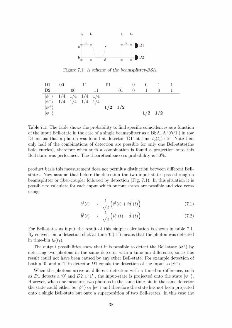
D1
D2
t
b
c
d
a
t 1 t 0
t
t 1 t 0
Figure 7.1: A scheme of the beamsplitter-BSA.
D1 00 11 01 0 0 1 1D2 00 11 01 0 1 0 1|φ+〉 1/4 1/4 1/4 1/4|φ−〉 1/4 1/4 1/4 1/4|ψ+〉 1/2 1/2|ψ−〉 1/2 1/2
Table 7.1: The table shows the probability to find specific coincidences as a functionof the input Bell-state in the case of a single beamsplitter as a BSA. A ‘0’(‘1’) in rowD1 means that a photon was found at detector ‘D1’ at time t0(t1) etc. Note thatonly half of the combinations of detection are possible for only one Bell-state(thebold entries), therefore when such a combination is found a projection onto thisBell-state was performed. The theoretical success-probability is 50%.
product basis this measurement does not permit a distinction between different Bell-states. Now assume that before the detection the two input states pass through abeamsplitter or fiber-coupler followed by detection (Fig. 7.1). In this situation it ispossible to calculate for each input which output states are possible and vice versausing
a†(t) → 1√2
(c†(t) + id†(t)
)(7.1)
b†(t) → 1√2
(ic†(t) + d†(t)
)(7.2)
For Bell-states as input the result of this simple calculation is shown in table 7.1.By convention, a detection click at time ‘0’(‘1’) means that the photon was detectedin time-bin t0(t1).
The output possibilities show that it is possible to detect the Bell-state |ψ+〉 bydetecting two photons in the same detector with a time-bin difference, since thisresult could not have been caused by any other Bell-state. For example detection ofboth a ‘0’ and a ‘1’ in detector D1 equals the detection of the input as |ψ+〉.
When the photons arrive at different detectors with a time-bin difference, suchas D1 detects a ‘0’ and D2 a ‘1’ , the input-state is projected onto the state |ψ−〉.However, when one measures two photons in the same time-bin in the same detectorthe state could either be |φ+〉 or |φ−〉 and therefore the state has not been projectedonto a single Bell-state but onto a superposition of two Bell-states. In this case the
38

D1
D2
Dt = t
t
b
e
f
a
t 1 t 0 e
id
t
t 1 t 0
t
t 2
Figure 7.2: General scheme of the three-BSA.
BSM was unsuccessful. Note that due to photon bunching the situation where bothphotons exit a different path at the same time does not occur.
This BSA has a success rate of 50% which corresponds to the maximal possiblesuccess rate that can be obtained while using only linear optics and no auxiliaryphotons as mentioned above. When using realistic detectors the success rate of thisBSA is 25%. This reduced efficiency is caused by the deadtime of the detectorswhich makes it impossible to detect one photon after another in a single detector(see also Fig. 4.5). This means the BSA is only capable of detecting |ψ−〉. Itis possible to measure |ψ+〉 adding a switch and additional detectors in order tosimulate a rapid detector. From now on this BSA is referred to as a BS-BSA. Notethat the equivalent BSA for polarization encoded qubits is capable of a 50% successrate since there are never two detections required by the same detector.
7.1.2 The three Bell-State analyzer
The 50% limit of success for a BSA doesn’t mean it is impossible to detect more thantwo Bell-states. Here we introduce a new type of BSA. It is capable of distinguishingmore than two Bell-states while still having the maximum success rate of 50%. Thisis possible by replacing the beamsplitter with a time-bin interferometer equivalentto the ones used to encode and decode time-bin qubits (Fig. 7.2). We will call thisBSA a 3-BSA. This BSA is capable of distinguishing three out of four Bell-states,but |φ+〉 and |ψ−〉 will only de discriminated 50% of the time as will be explainedshortly.
Two qubits enter in port a and b, respectively. The first beamsplitter acts like theBS-BSA, allowing the distinction of two Bell-states (|ψ+〉 and |ψ−〉) if the photonswere detected. A second possibility for interference is added by another BS for whichthe inputs are the outputs of the first BS, with one path having a delay correspondingto the time-bin separation τ . The two-photon effects on this beamsplitter lead tofully distinguishable photon combinations of one of the two remaining Bell-states(|φ+〉) while still allowing a partial distinction of the first two.
One might expect that when it is possible to measure three out of four statesthat the fourth, non-measured, state can simply be inferred from a negative mea-surement result of the three measurable states. This is, however, not the case. Theabove described measurement is a positive operator valued measure (POVM) with21 possible outcomes, some of these outcomes are only possible for one of the four
39

Bell-states. Therefore when such an outcome is detected it unambiguously discrim-inates the corresponding input Bell-state. The rest of the 21 outcomes can resultfrom more than one input Bell-state. In other words, their results are ambiguousand the input state is not projected onto a single Bell-state but onto a superpositionof Bell-states.
The state after the interferometer can be calculated for any input-state using:
a†(t) → 1√4[−e†(t) + eiθe†(t + τ) + if †(t) + ieiθf †(t + τ)] (7.3)
b†(t) → 1√4[ie†(t) + ieiθe†(t + τ) + f †(t)− eiθf †(t + τ)] (7.4)
where i†(j) is the creation operator of a photon at time j in mode i. When theinput-states are qubits and the photons are detected after the interferometers thedetection-patterns are readily calculated and are shown in Table 7.2. The outputcoincidences on detectors D1 (port e) and D2 (port f) are shown as a function ofa Bell-state as input. By convention, a detection at time ‘0’ means that the photonwas in time t0 after the BSA-interferometer. This is only possible if it took the shortpath in the BSA and it was originally a photon in time-bin t0 (Fig. 7.2). Similarlya detection at time ‘1’ means that either the photon was originally in t1 and tookthe short path of the BSA interferometer or it was in t0 and took the long path. Adetection at time ‘2’ means the photon was in t1 and took the long path. In Table7.2 we see that some of the detection combinations corresponds to a single Bell-state and therefore the measurement is unambiguous. For the other cases the resultcould have been caused by two Bell-states, i.e. the result is ambiguous and henceinconclusive. More specifically, the Bell-state |ψ+〉 is detected with probability 1,|φ−〉 is never detected and both |ψ−〉 and |φ+〉 are detected with probability 1/2.
The above described approach is correct in the case were the separation τ of theincoming qubits is equal to the time-bin separation caused by the interferometer. Ifthis in not exactly the case and the interferometer creates a time-bin separation ofτ + nλθ
2πc, where θ is a phase, the situation is slightly more complicated. In such a
case, our BSA still distinguishes 3 Bell-states, but these are no longer the standardBell-states but are:
|φ′±〉 = |0, 0〉 ± e2iθ|1, 1〉 = (σθ ⊗ σθ)|φ±〉 (7.5)
|ψ′±〉 = eiθ(|0, 1〉 ± |1, 0〉) = eiθ|ψ±〉 (7.6)
Here σθ = |0〉〈0| + eiθ|1〉〈1| is a phase shift of θ to be applied to the time bin |1〉.These new Bell-states are equivalent to the standard states except that the |1〉 isreplaced by eiθ|1〉 for each of the input modes.
In a realistic experimental environment the success probabilities of the BSA areaffected by detector limitations. Again this is because existing photon-detectorsare not fast enough to distinguish photons which follow each other closely in asingle measurement cycle. When including this limitation we find that the maximalprobabilities of success in our experimental setup are reduced to 1/2, 1/4 and 1/2for |ψ′+〉, |ψ′−〉 and |φ′+〉, respectively. This leads to an overall probability of success
40

D1
0011
2201
0212
02
11
01
20
2D
200
1122
0102
120
21
01
21
20
|φ′+〉
1/16
1/16
1/16
1/16
1/8
1/8
1/2
|φ′−〉
1/16
1/16
1/4
1/4
1/16
1/16
1/8
1/8
|ψ′+〉
1/8
1/8
1/8
1/8
1/8
1/8
1/8
1/8
|ψ′−〉
1/4
1/4
1/8
1/8
1/8
1/8
Tab
le7.
2:T
he
table
show
sth
epro
bab
ility
tofind
any
ofth
e21
pos
sible
coin
ciden
ces
asa
funct
ion
ofth
ein
put
Bel
l-st
ate.
A‘0
’in
row
D1
mea
ns
that
aphot
onw
asfo
und
atdet
ecto
r‘D
1’an
dat
ati
me
corr
espon
din
gto
the
phot
onhav
ing
take
nth
esh
ort
pat
hin
the
inte
rfer
omet
eran
dit
was
orig
inal
lya
phot
onin
tim
e-bin
t 0,
a‘1
’co
rres
pon
ds
tot 0
+1×
τw
ith
τco
rres
pon
din
gto
ath
ediff
eren
cebet
wee
nth
eti
me-
bin
san
d‘2
’re
fers
tot 0
+2×
τ.
Not
eth
atse
vera
lco
mbin
atio
ns
ofdet
ecti
onar
epos
sible
for
only
one
Bel
l-st
ate(
the
bol
den
trie
s),th
eref
ore
when
such
aco
mbin
atio
nis
found
aB
ell-st
ate
Mea
sure
men
tw
asper
form
ed.
The
theo
reti
cal
pro
bab
ility
ofa
succ
essf
ulm
easu
rem
ent
is0.
5w
hic
his
the
opti
mal
valu
eusi
ng
only
linea
rop
tics
[51]
.
41

Bell state
analyzer
Qubit source EPR source
a b c
U
Figure 7.3: General scheme of the quantum teleportation protocol.
of 5/16 which is larger by 25% than the success rate of the BS-BSA discussed insection 7.1.
The detector-limitation could be partially eliminated by using a beamsplitter andtwo detectors in order to simulate a rapid multi-photon detector half of the time,or it could be completely eliminated by using an ultra-fast optical switch (sendingeach time-bin to a different detector). Both of these methods are associated with adecrease in signal-to-noise ratio. This is caused by additional noise from the addeddetector and by additional losses from the optical switch, respectively. Note thatas was the case for the BS-BSA the polarization equivalent of the 3-BSA does notencounter this problem.
7.2 Quantum Teleportation
In order to show the functioning of the 3-BSA we performed a teleportation-experiment.The protocol is very similar to the entanglement swapping shown in the last chapter.An entangled photon-pair is created and distributed, the qubit to be teleported issent to the BSA along with half of the entangled pair and a BSM is performed onthem. As a function of the result of this BSM a unitary transformation is performedon the remaining photon which is then equal to the original qubit (Fig. 7.3). In thecase of the 3-BSA a small adaptation of the Bell-states and unitary transformationsis required to take account of the phase of the interferometer:
|ζabc〉 = |ζ〉a ⊗ |φ+〉 (7.7)
=1√4(|ψ′+〉ab
⊗ e−iθσx|ζ〉c (7.8)
+|ψ′−〉ab ⊗ e−iθσxσz|ζ〉c+|φ′+〉ab ⊗ σ2θ|ζ〉c+|φ′−〉ab ⊗ σzσ2θ|ζ〉c
where |ζ〉 is the qubit to be teleported, σx is a bitflip and σz a phaseflip.
42
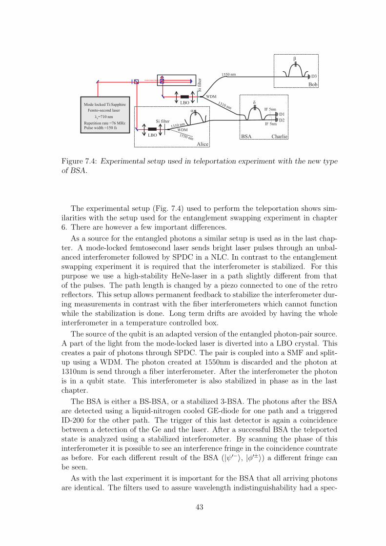
LBO
WDM
Si filter
D1
WDM
Si
filt
er
b
Femto-second laser
Repetition rate =76 MHz
Pulse width =150 fs
Mode locked Ti:Sapphire
lp=710 nm
LBO
D2
D3
IF 5nm
IF 5nm
1550 nm
1310 nm
1550 nm
1310 nm
d
a
Alice
Charlie
Bob
BSA
Figure 7.4: Experimental setup used in teleportation experiment with the new typeof BSA.
The experimental setup (Fig. 7.4) used to perform the teleportation shows sim-ilarities with the setup used for the entanglement swapping experiment in chapter6. There are however a few important differences.
As a source for the entangled photons a similar setup is used as in the last chap-ter. A mode-locked femtosecond laser sends bright laser pulses through an unbal-anced interferometer followed by SPDC in a NLC. In contrast to the entanglementswapping experiment it is required that the interferometer is stabilized. For thispurpose we use a high-stability HeNe-laser in a path slightly different from thatof the pulses. The path length is changed by a piezo connected to one of the retroreflectors. This setup allows permanent feedback to stabilize the interferometer dur-ing measurements in contrast with the fiber interferometers which cannot functionwhile the stabilization is done. Long term drifts are avoided by having the wholeinterferometer in a temperature controlled box.
The source of the qubit is an adapted version of the entangled photon-pair source.A part of the light from the mode-locked laser is diverted into a LBO crystal. Thiscreates a pair of photons through SPDC. The pair is coupled into a SMF and split-up using a WDM. The photon created at 1550nm is discarded and the photon at1310nm is send through a fiber interferometer. After the interferometer the photonis in a qubit state. This interferometer is also stabilized in phase as in the lastchapter.
The BSA is either a BS-BSA, or a stabilized 3-BSA. The photons after the BSAare detected using a liquid-nitrogen cooled GE-diode for one path and a triggeredID-200 for the other path. The trigger of this last detector is again a coincidencebetween a detection of the Ge and the laser. After a successful BSA the teleportedstate is analyzed using a stabilized interferometer. By scanning the phase of thisinterferometer it is possible to see an interference fringe in the coincidence countrateas before. For each different result of the BSA (|ψ′−〉, |φ′±〉) a different fringe canbe seen.
As with the last experiment it is important for the BSA that all arriving photonsare identical. The filters used to assure wavelength indistinguishability had a spec-
43
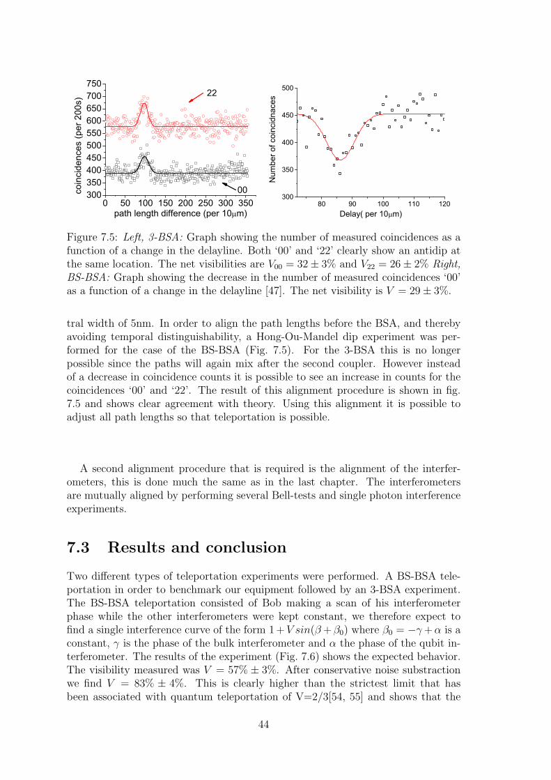
0 50 100 150 200 250 300 350300350400450500550600650700750
coin
cide
nces
(per
200
s)
path length difference (per 10 m)
22
0080 90 100 110 120
300
350
400
450
500
Num
ber o
f coi
ncid
nace
s
Delay( per 10 m)
Figure 7.5: Left, 3-BSA: Graph showing the number of measured coincidences as afunction of a change in the delayline. Both ‘00’ and ‘22’ clearly show an antidip atthe same location. The net visibilities are V00 = 32± 3% and V22 = 26± 2% Right,BS-BSA: Graph showing the decrease in the number of measured coincidences ‘00’as a function of a change in the delayline [47]. The net visibility is V = 29± 3%.
tral width of 5nm. In order to align the path lengths before the BSA, and therebyavoiding temporal distinguishability, a Hong-Ou-Mandel dip experiment was per-formed for the case of the BS-BSA (Fig. 7.5). For the 3-BSA this is no longerpossible since the paths will again mix after the second coupler. However insteadof a decrease in coincidence counts it is possible to see an increase in counts for thecoincidences ‘00’ and ‘22’. The result of this alignment procedure is shown in fig.7.5 and shows clear agreement with theory. Using this alignment it is possible toadjust all path lengths so that teleportation is possible.
A second alignment procedure that is required is the alignment of the interfer-ometers, this is done much the same as in the last chapter. The interferometersare mutually aligned by performing several Bell-tests and single photon interferenceexperiments.
7.3 Results and conclusion
Two different types of teleportation experiments were performed. A BS-BSA tele-portation in order to benchmark our equipment followed by an 3-BSA experiment.The BS-BSA teleportation consisted of Bob making a scan of his interferometerphase while the other interferometers were kept constant, we therefore expect tofind a single interference curve of the form 1+V sin(β +β0) where β0 = −γ +α is aconstant, γ is the phase of the bulk interferometer and α the phase of the qubit in-terferometer. The results of the experiment (Fig. 7.6) shows the expected behavior.The visibility measured was V = 57% ± 3%. After conservative noise substractionwe find V = 83% ± 4%. This is clearly higher than the strictest limit that hasbeen associated with quantum teleportation of V=2/3[54, 55] and shows that the
44
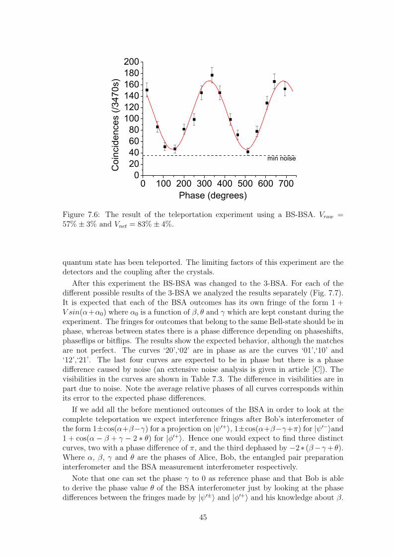
0 100 200 300 400 500 600 700020406080100120140160180200
Coi
ncid
ence
s (/3
470s
)
Phase (degrees)
min noise
Figure 7.6: The result of the teleportation experiment using a BS-BSA. Vraw =57%± 3% and Vnet = 83%± 4%.
quantum state has been teleported. The limiting factors of this experiment are thedetectors and the coupling after the crystals.
After this experiment the BS-BSA was changed to the 3-BSA. For each of thedifferent possible results of the 3-BSA we analyzed the results separately (Fig. 7.7).It is expected that each of the BSA outcomes has its own fringe of the form 1 +V sin(α+α0) where α0 is a function of β, θ and γ which are kept constant during theexperiment. The fringes for outcomes that belong to the same Bell-state should be inphase, whereas between states there is a phase difference depending on phaseshifts,phaseflips or bitflips. The results show the expected behavior, although the matchesare not perfect. The curves ‘20’,‘02’ are in phase as are the curves ‘01’,‘10’ and‘12’,‘21’. The last four curves are expected to be in phase but there is a phasedifference caused by noise (an extensive noise analysis is given in article [C]). Thevisibilities in the curves are shown in Table 7.3. The difference in visibilities are inpart due to noise. Note the average relative phases of all curves corresponds withinits error to the expected phase differences.
If we add all the before mentioned outcomes of the BSA in order to look at thecomplete teleportation we expect interference fringes after Bob’s interferometer ofthe form 1±cos(α+β−γ) for a projection on |ψ′+〉, 1±cos(α+β−γ+π) for |ψ′−〉and1 + cos(α − β + γ − 2 ∗ θ) for |φ′+〉. Hence one would expect to find three distinctcurves, two with a phase difference of π, and the third dephased by −2∗ (β−γ + θ).Where α, β, γ and θ are the phases of Alice, Bob, the entangled pair preparationinterferometer and the BSA measurement interferometer respectively.
Note that one can set the phase γ to 0 as reference phase and that Bob is ableto derive the phase value θ of the BSA interferometer just by looking at the phasedifferences between the fringes made by |ψ′±〉 and |φ′+〉 and his knowledge about β.
45

0 200 400 600 800 1000 120080
100120140160180200220240260280300320340
Coi
ncid
ance
s (p
er 4.4h)
Phase (degrees)
SM ML MS LM
-200 0 200 400 600 800 1000 1200 1400
60
80
100
120
140
160
180
200
220
Coi
ncid
ence
s (p
er 4.4h)
Phase (degrees)
"02" "20"
Figure 7.7: Measured coincidance counts as a function of phase. Left: BSA-results‘01’, ‘10’, ‘12’ and ‘21’. Right: BSA-results ‘02’ and ‘20’. The fringe for BSA-results‘11’ is shown in Fig. 7.8 as |ψ+〉.
Result 3BSA Vraw Vnet ρraw ρnet Praw Pnet
|ψ+〉|01〉 35± 3 61± 6 98 ± 4 -81±5 13±1 14±1|10〉 43± 3 83± 13 159 ± 4 126±8 11±1 13±1|12〉 18± 3 72± 7 160 ± 7 -22±4 14±1 7±1|21〉 13± 2 55± 2 97 ± 9 136±1 17±1 10±1
|φ+〉 |11〉 43± 3 64± 13 -44 ± 3 -18±10 29±1 41±1
|ψ−〉 |02〉 39± 5 62± 10 -49 ± 4 153±8 8±1 6±1|20〉 38± 4 36± 8 -32 ± 4 -80±12 9±1 9±1
|ψ+〉 22± 1 51± 3 -49 ± 3 -49± 3 54±1 43±1|φ+〉 43± 3 69± 10 136 ± 3 139± 7 29±1 41±1|ψ−〉 38± 5 55± 3 140 ± 6 136± 3 17±1 15±1
Table 7.3: For each of the different detection possibilities the fitted result are shownbefore and after noise correction.‘V ’ refers to the Visibility (%), ‘ρ’ to a phase-shift(degrees) and ‘P’ to the normalized probabilities of a coincidence detection (%) .The results for the Bell-states are fitted after adding the corresponding coincidences.
46
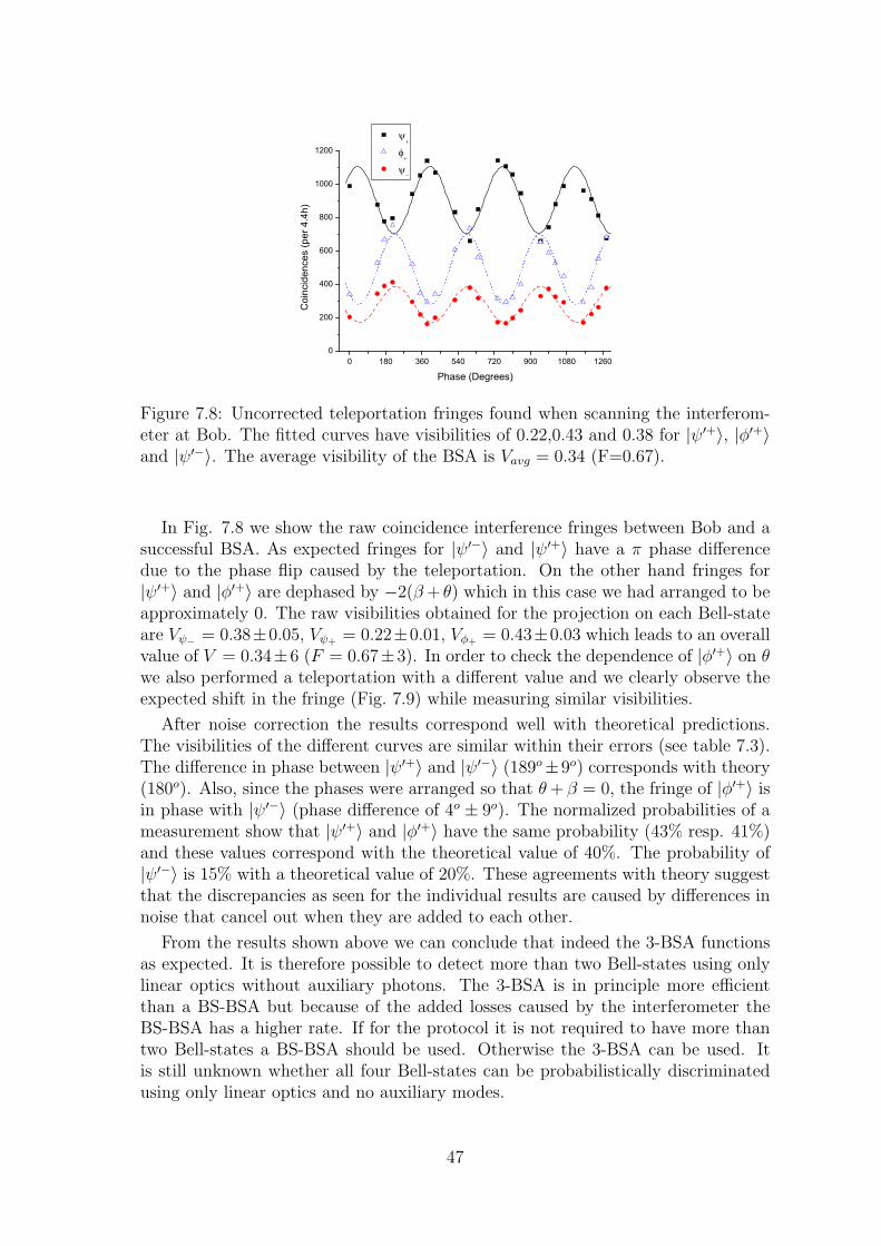
0 180 360 540 720 900 1080 12600
200
400
600
800
1000
1200
Coi
ncid
ence
s (p
er 4.4h)
Phase (Degrees)
Figure 7.8: Uncorrected teleportation fringes found when scanning the interferom-eter at Bob. The fitted curves have visibilities of 0.22,0.43 and 0.38 for |ψ′+〉, |φ′+〉and |ψ′−〉. The average visibility of the BSA is Vavg = 0.34 (F=0.67).
In Fig. 7.8 we show the raw coincidence interference fringes between Bob and asuccessful BSA. As expected fringes for |ψ′−〉 and |ψ′+〉 have a π phase differencedue to the phase flip caused by the teleportation. On the other hand fringes for|ψ′+〉 and |φ′+〉 are dephased by −2(β + θ) which in this case we had arranged to beapproximately 0. The raw visibilities obtained for the projection on each Bell-stateare Vψ− = 0.38±0.05, Vψ+ = 0.22±0.01, Vφ+ = 0.43±0.03 which leads to an overallvalue of V = 0.34±6 (F = 0.67±3). In order to check the dependence of |φ′+〉 on θwe also performed a teleportation with a different value and we clearly observe theexpected shift in the fringe (Fig. 7.9) while measuring similar visibilities.
After noise correction the results correspond well with theoretical predictions.The visibilities of the different curves are similar within their errors (see table 7.3).The difference in phase between |ψ′+〉 and |ψ′−〉 (189o±9o) corresponds with theory(180o). Also, since the phases were arranged so that θ + β = 0, the fringe of |φ′+〉 isin phase with |ψ′−〉 (phase difference of 4o ± 9o). The normalized probabilities of ameasurement show that |ψ′+〉 and |φ′+〉 have the same probability (43% resp. 41%)and these values correspond with the theoretical value of 40%. The probability of|ψ′−〉 is 15% with a theoretical value of 20%. These agreements with theory suggestthat the discrepancies as seen for the individual results are caused by differences innoise that cancel out when they are added to each other.
From the results shown above we can conclude that indeed the 3-BSA functionsas expected. It is therefore possible to detect more than two Bell-states using onlylinear optics without auxiliary photons. The 3-BSA is in principle more efficientthan a BS-BSA but because of the added losses caused by the interferometer theBS-BSA has a higher rate. If for the protocol it is not required to have more thantwo Bell-states a BS-BSA should be used. Otherwise the 3-BSA can be used. Itis still unknown whether all four Bell-states can be probabilistically discriminatedusing only linear optics and no auxiliary modes.
47
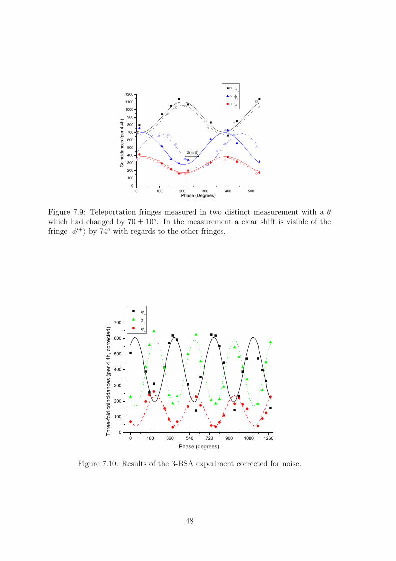
0 100 200 300 400 5000
100
200
300
400
500
600
700
800
900
1000
1100
1200
Coi
ncid
ance
s (p
er 4.4h)
Phase (Degrees)
2( )
Figure 7.9: Teleportation fringes measured in two distinct measurement with a θwhich had changed by 70 ± 10o. In the measurement a clear shift is visible of thefringe |φ′+〉 by 74o with regards to the other fringes.
0 180 360 540 720 900 1080 12600
100
200
300
400
500
600
700
Thre
e-fo
ld c
oinc
idan
ces
(per
4.4
h, c
orre
cted
)
Phase (degrees)
Figure 7.10: Results of the 3-BSA experiment corrected for noise.
48

Chapter 8
Out-of-the-lab Teleportation [D][P1-P3]
8.1 Introduction
The goal of QC is the distribution of quantum states between different locations. Sofar the experiments discussed have all been experiments that were done in the samelab, albeit in a configuration ready for work outside the lab. To prove that thesetechniques work as well outside of a controlled laboratory environment we performeda teleportation experiment between our lab and a Swisscom (Swiss national telecomprovider) switching station.
8.2 Experimental improvements
Quantum teleportation experiments have been performed that use optical fiber tosimulate a distance[13] or that are ‘out-of-the-lab’ but without prior entanglementdistribution and creation [58, 56]. No experiment has been performed which usesprior entanglement distribution outside of the laboratory. This means the Bell-statemeasurement always took place before the remaining photon was distributed. In allexperiments a single laser pulse was used to create all photons. We performed thefollowing experiment in which all these points were addressed.
The setup (Fig. 8.1) consists of a femtosecond laser at 711nm. The pulses comingfrom this laser are split in two using a variable coupler. One part is sent through anunbalanced bulk interferometer (stabilized as before using a stable HeNe) followedby SPDC in a LBO NLC. The other part of the laser is send through another LBONLC again to create photon-pairs using SPDC. The created photons are separatedfrom the pump photons using Si-filters and coupled into SMFs. A WDM is used tosplit the pairs.
The pair of photons created after the interferometer is time-bin entangled. Thephoton at 1310nm is sent to a rudimentary quantum memory, namely a fiber witha length of 179.7m on a spool. The photon at 1555nm is sent out of the lab to aSwisscom switching station. For this purpose a dedicated fiber is used. The fiber is
49

Femtosecond
laser
l/2 PBS
LBO
Si-filter
WDM
50/50 Coupler
&
Stabilized
Interferometer
Stabilized
InterferometerComputer
WDM
Laboratory
Swisscom
550 m
800 m
800 m
Quantum channel
Classical channel
Heralding
detector
Delay
adjustable delay
QM
QM
trigger
trigger
Polarization
controller
Figure 8.1: Scheme of the experimental setup. The Swisscom location was a switch-ing station located 550m from the laboratory. QM stands for quantum memory, inthis case a long fiber on a spool. PBS stands for polarizing beamsplitter
50

Swisscom
Laboratory
550m
fiber
length
800m
Figure 8.2: Photograph of the area around the laboratory. In the bottom left corneris our lab while in the top right corner is the Swisscom switching station. Thedistance between them is about 550m whereas the fiber in between them has alength of 800m
a standard single-mode telecommunications fiber as used throughout the Swisscomnetwork. The length of the fiber is 800m while the physical distance between thelab and the switching station is 550m (Fig. 8.2).
From the other source of photons the 1310nm photon is sent into an optical delay,in this case a fiber with a length of 177m. The difference in length between the twofiber spools is adjusted so that it corresponds to a single cycle of the mode-lockedlaser. In other words, the photons pairs that will be used for the BSA are not createdby the same pulse but by two subsequent pulses. This is a step towards independentphoton-pair sources[57, 59]. The photon at 1555nm of this pair is detected by anid200 single photon detector. This detector serves as a heralding detector and is ofno influence on the teleportation protocol other than allowing an improvement ofthe SNR at the cost of a reduced coincidence rate.
After the 177m fiber QM the photon passes through a stabilized unbalanced fiberinterferometer such as those described earlier in this thesis (Fig. 6.4). Only at thispoint is the qubit encoded onto the photon. Since this only takes place after thedelay the 1555nm photon that has been send to the Swisscom station has already
51

100
150
200
250
300
350
400
0 500 1000 1500 2000 2500
Cou
nts/
20s
Travel delay (µm)
Figure 8.3: Result of the Hong-Ou-Mandel experiment used to align the fiber lengthsin the setup. The two different dips are for coincidences at two different time, namely‘00’ and ‘11’. The raw visibilities are V00 = 0.25± 0.02 and V11 = 0.26± 0.02.
left the lab at this point.
The 1310nm photons are sent to a BS-BSA. The detectors in this BSA are againa Ge-diode and an id200 InGaAs-diode. The trigger for the InGaAs is given bycoincidences between the laser and a click on the Ge-diode. If the BSA is successfula signal is sent to the Swisscom station though an optical fiber different from thequantum channel. This signal will trigger the detector used at the switching station.
The 1555nm photon that was sent to the switching station is first sent into anotherquantum memory (fiber on spool). After this the photon is sent through a stabilizedinterferometer which is used to analyze the result of the teleportation. The photonis detected using an id200 InGaAs detector which was triggered by the result of theBSA. The countrate is registered by computer.
All the stabilization of the interferometers is done locally. Since the fiber interfer-ometers cannot be used during stabilization a TCP/IP link was used to perform thestabilization of all the interferometers at the same time. This technique optimizesthe duty cycle of the experiment.
In order for the BSA to function the incoming photons are filtered to an identical5nm spectrum. Furthermore alignment of the fiber lengths is tested by performingHOM-dip experiments as explained in the previous chapters. Its result (Fig. 8.3)show clear indistinguishability of the photons with corrected visibilities near themaximum of 1
3. Note that the photons used for this HOM-dip are not created by
the same pulse because of the difference in the fiber delays.
This experiment requires one additional stabilization. Since the photons needto arrive on the BSA at the same time the length of the delay fibers they travelthrough should remain stable. However fluctuations in temperature mean that thelength and refractive index of the fibers are not constant. In order to minimize theeffects of these fluctuation both fibers were placed in a common isolation box sothat fluctuations were equal for both spools. Two effects remain that influence thetime of arrival. First of all the repetition frequency of the mode-locked laser has asmall dependance on temperature. Second, the fluctuation of the 2.7m difference in
52
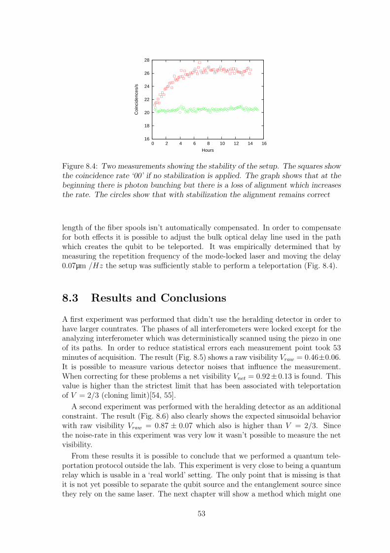
16
18
20
22
24
26
28
0 2 4 6 8 10 12 14 16
Coi
ncid
ence
s/s
Hours
Figure 8.4: Two measurements showing the stability of the setup. The squares showthe coincidence rate ‘00’ if no stabilization is applied. The graph shows that at thebeginning there is photon bunching but there is a loss of alignment which increasesthe rate. The circles show that with stabilization the alignment remains correct
length of the fiber spools isn’t automatically compensated. In order to compensatefor both effects it is possible to adjust the bulk optical delay line used in the pathwhich creates the qubit to be teleported. It was empirically determined that bymeasuring the repetition frequency of the mode-locked laser and moving the delay0.07µm /Hz the setup was sufficiently stable to perform a teleportation (Fig. 8.4).
8.3 Results and Conclusions
A first experiment was performed that didn’t use the heralding detector in order tohave larger countrates. The phases of all interferometers were locked except for theanalyzing interferometer which was deterministically scanned using the piezo in oneof its paths. In order to reduce statistical errors each measurement point took 53minutes of acquisition. The result (Fig. 8.5) shows a raw visibility Vraw = 0.46±0.06.It is possible to measure various detector noises that influence the measurement.When correcting for these problems a net visibility Vnet = 0.92±0.13 is found. Thisvalue is higher than the strictest limit that has been associated with teleportationof V = 2/3 (cloning limit)[54, 55].
A second experiment was performed with the heralding detector as an additionalconstraint. The result (Fig. 8.6) also clearly shows the expected sinusoidal behaviorwith raw visibility Vraw = 0.87 ± 0.07 which also is higher than V = 2/3. Sincethe noise-rate in this experiment was very low it wasn’t possible to measure the netvisibility.
From these results it is possible to conclude that we performed a quantum tele-portation protocol outside the lab. This experiment is very close to being a quantumrelay which is usable in a ‘real world’ setting. The only point that is missing is thatit is not yet possible to separate the qubit source and the entanglement source sincethey rely on the same laser. The next chapter will show a method which might one
53

20
30
40
50
60
70
80
90
100
110
120
200 300 400 500 600 700 800 900 1000 1100
Coi
ncid
ence
s/32
10s
Phase (degrees)
Vnet = 0.92 +/- 0.13
noise level
Figure 8.5: Result of the teleportation experiment. The fit shows a net visibility ofVnet = 0.92± 0.13
0
5
10
15
20
25
30
35
40
200 250 300 350 400 450 500 550 600 650 700
Coi
ncid
ence
s/21
400s
Phase (degrees)
Vraw=0.87 +/- 0.07
Figure 8.6: Result of the teleportation experiment when using a heralded qubit-source. The raw visibility is Vraw = 0.87± 0.07.
54

day allow a teleportation with multiple lasers.
55

Chapter 9
Synchronized photon sources [E]
9.1 Introduction
Consider the following situation: two independent photon-pair sources are used toperform an entanglement swapping experiment. For the BSM it is required thatphotons coming from the two sources are completely indistinguishable. This meansthat the time of arrival at the BSM has to be identical for both photons. In otherwords the coherence length must be longer than the temporal uncertainty. In orderto achieve this most experiments use pulsed synchronized sources as shown in pre-vious chapters. The synchronization is achieved by using a single laser pulse whichgenerates two photon-pairs in one crystal in a back-and-forth configuration[12] or intwo separate crystals each of which creates one pair[58]. In the previous chapter wealso showed the use of two crystals and different laser pulses. Although such systemsare practical they are not sufficient when trying to do long range experiments. Ifit is desired to have photon-pair sources at different locations, the use of only onelaser would mean sending high-power pulses through optical fibers. The pulses willbe distorted in the fibers by different effects and also compensation for path lengthfluctuations is required.
One logical alternative would be to use two different pulsed lasers which aresynchronized. Innovative experiments on this subject have been done[57, 59] thathave shown that in principle it is possible to create indistinguishable photons withindependent lasers. However, neither of the techniques developed in these experi-ments can be easily used to truly make a quantum repeater. In the first case[57] thetwo independent sources had a common optical element, making it impossible tophysically separate both sources. And in both experiments the photons have shortcoherence lengths, making the system very sensitive to path length fluctuations anddrifts of repetition frequency and adding difficulty to synchronization at distance.When using optical fibers at telecommunication wavelengths these path lengths canfluctuate up to the order of several millimeters per day[60]. In terms of jitter thiscorresponds to several picoseconds. Therefore an active control of path length isrequired. As an alternative the next sections show our efforts in making separablesources that are useful for quantum repeaters and have a high tolerance againstthese path length fluctuations. Another interesting approach is using continuous
57

Figure 9.1: Effects of a displacement on the overlap between two functions. The toptwo images show a clear reduction of the overlapping area (black) of two identical butdisplaced functions when their displacement is increased. The bottom two graphsshow a less important reduction since the functions are wider.
wave sources[61], this has its own particularities and won’t be discussed here.
9.2 Narrow-band photons
An important parameter for the quality of synchronization is jitter. One can easilyimagine that the quality of a BSA is greatly reduced if one or both sources have alarge jitter because this introduces temporal distinguishability between the createdphotons. If we assume the use of pulsed lasers and parametric-downconversion tocreate photon-pairs several different sources of jitter can be identified. First of allthere is the intrinsic jitter, every laser has a certain uncertainty in the time ofemission of a pulse. This jitter is minimal in a free-running modelocked-laser butcan be important in pulsed diode-lasers. Second, there is a timing jitter which iscreated by the synchronization system itself. Finally there is the path-length jitter asmentioned before. Obviously an effort has to be made to limit all of these quantities,but one method to overcome them all is to increase the coherence length of thephoton-pairs(Fig. 9.1) since this will effectively reduce the jitter per pulsewidth.The result of such a change is best illustrated by calculating the visibility of aHOM-dip.
Consider the probability P of photon bunching when two identical photons arriveat a different time on a beamsplitter.
Pbunch =1
2∗
((∫f ∗(t)f(t + τ)dt
)2
+ 1
)(9.1)
where f(t) is the amplitude of the temporal distribution function of the photon andτ is the difference of arrival time. When assuming a gaussian distribution for thephotons we find:
f(t) =√
Ne−8ln2 t2
w2 (9.2)
Pbunch =1
2
((N
∫e−
8ln2w2 (t2+(t+τ)2)dt
)2
+ 1
)(9.3)
=1
2
(e−
4ln2w2 τ2
+ 1)
(9.4)
58
here N is a normalization factor and w is the FWHM of Pbunch. It is convenient torewrite this last formula in dimensionless units:
∆ ≡ τ
w(9.5)
Pbunch =1
2
(e−4ln2∆2
+ 1)
(9.6)
where ∆ is the amount of FWHMs the photons arrive apart.
When considering jitter the time-of-arrival difference will fluctuate. There is aprobability Pj to find the photon at a delay ∆ of:
Pj(∆, wj) =2
wj
√ln2
πe−4ln2∆2
w2j (9.7)
where we assumed a gaussian distribution with FWHM wj. When performing astandard HOM-dip experiment with these parameters the average visibility of thesystem equals
V =
∫Pj(∆, wj)V (∆)d∆ (9.8)
=
∫Pj(∆, wj) (2Pbunch(∆)− 1) d∆ (9.9)
=2
wj
√ln2
π
∫e−4ln2∆2
(1
1+w2j
)
d∆ (9.10)
=1√
1 + w2j
(9.11)
This result shows (Fig. 9.2) a clear decrease of the visibility as a result of time-of-arrival jitter. It also shows that some jitter can be tolerated without a dramaticloss in visibility as long as wj remains small. The limit on the overall jitter at whichit is still possible to see a visibility high enough to violate Bell’s inequality whenperforming Bell-tests (
√0.5) is a jitter equal to the FWHM of the displacement per
pulse length.
If we consider Fourier limited gaussian pulses the pulse width is given by thecoherence length lc.
lc =2ln2
π
λ20
∆λ(9.12)
where λ0 the central wavelength and ∆λ the spectral FWHM. In order to increasethe coherence length and thus effectively reducing wj the only viable option is tohave a very small ∆λ. The generation of photon-pairs with SPDC usually creates alarge spectrum which can easily exceed several dozens of nm. At telecommunicationwavelengths (λ0 = 1550nm) such a spectrum corresponds to coherence lengths ofthe order of 10−5m which is not enough since in previous experiments path length
59

0.0 0.2 0.4 0.6 0.8 1.0 1.2 1.4 1.6 1.8 2.00.50
0.55
0.60
0.65
0.70
0.75
0.80
0.85
0.90
0.95
1.00
1+w2j
Vis
ibili
ty
wj (FWHM of displacement per FWHM of pulse)
0.5
V=1
Figure 9.2: Visibility as a function of wj. A visibility of√
0.5 corresponds to wj = 1(dashed lines).
fluctuations of up the several mm were found. One obvious approach is to use onlya small part of the spectrum generated by the source (spectral filtering).
If coherence lengths of the order of a cm are desired extremely narrow filtersare required. The filters used for our experiment are a combination of a fiber-bragg-grating(FBG) and a phase-shifted FBG. The phase-shifted FBG has an Airy-function shaped transmission spectrum with a width of about 40pm (ωi). Therejection of other wavelengths only works for a couple of nm so in order to filterthem a standard FBG is used (Fig. 9.3). This combination is cascaded so it ispossible to select pairs of photons, the second filter combination has a transmissionwidth of 120pm (ωs). The two transmission wavelengths are symmetrically locatedaround the pump wavelength (ωp).
In order to have a well defined correlation between the wavelengths of the photon-pairs it is required to filter the pump-photons. Since we use large coherence lengthsthe relatively large pulse length of the pump pulses is not a problem[62].
The visibility of a HOM-dip directly shows the maximum visibility that can beachieved in other QC experiments such as entanglement swapping. This makesit a very useful test, however other methods can also be used to show that twosources are synchronized. One alternative is to perform a cross-correlation measure-ment. This has the advantage that it is a lot simpler but the disadvantage thatit only test the synchronization and not the other important parameters such asindistinguishability. It can be done by passing light form two sources through anon-linear crystal(NLC) cut for type II phasematching. When both pulses arrive atthe same time in the NLC there will be frequency-doubling with an intensity de-pendant on their overlap. Assuming gaussian functions this means that the FWHM
of the detectable frequency-doubled light is equal to wfd =√
w2s1 + w2
s2 + w2j where
wfd, ws1, ws2 and wj are the FWHM for the frequency-doubled light, first source,second source and the synchronization jitter respectively. In order to find the valueof wj it is required to first measure the pulse lengths ws1 and ws2 using an auto-correlation measurement. This is similar to the cross-correlation but both sources
60
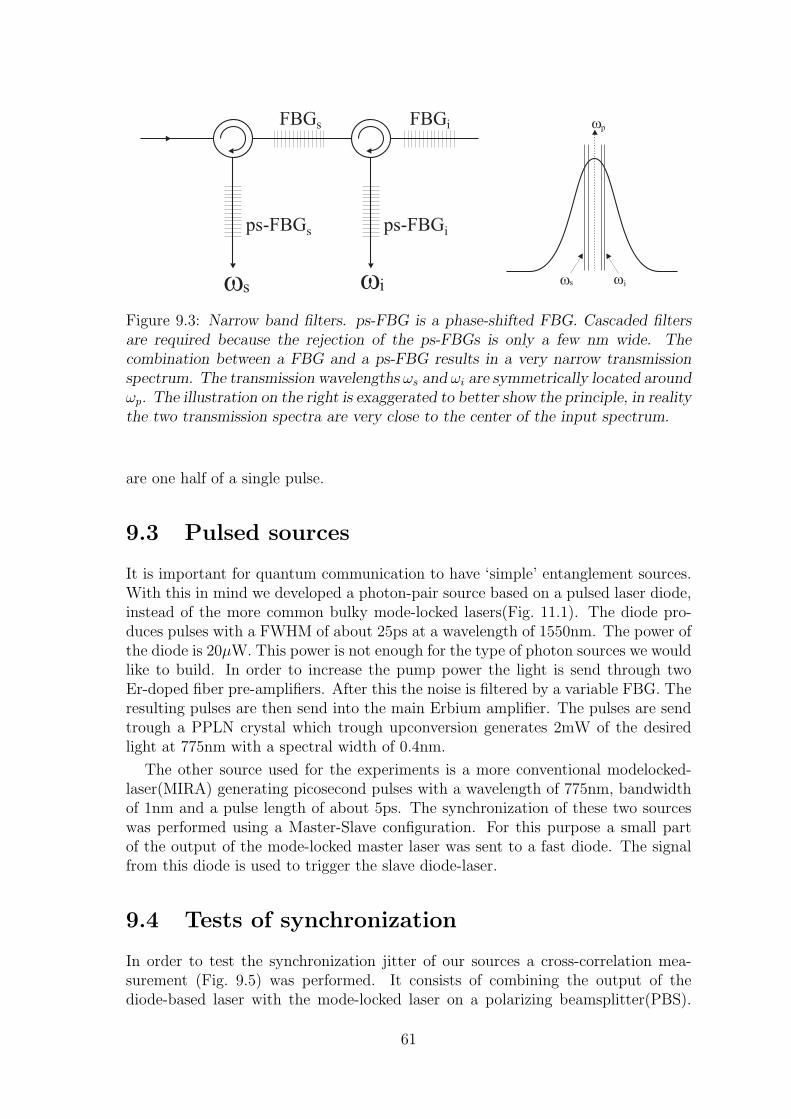
ps-FBG
FBGs
s ps-FBG
FBGi
i
wp
wiwsws wi
Figure 9.3: Narrow band filters. ps-FBG is a phase-shifted FBG. Cascaded filtersare required because the rejection of the ps-FBGs is only a few nm wide. Thecombination between a FBG and a ps-FBG results in a very narrow transmissionspectrum. The transmission wavelengths ωs and ωi are symmetrically located aroundωp. The illustration on the right is exaggerated to better show the principle, in realitythe two transmission spectra are very close to the center of the input spectrum.
are one half of a single pulse.
9.3 Pulsed sources
It is important for quantum communication to have ‘simple’ entanglement sources.With this in mind we developed a photon-pair source based on a pulsed laser diode,instead of the more common bulky mode-locked lasers(Fig. 11.1). The diode pro-duces pulses with a FWHM of about 25ps at a wavelength of 1550nm. The power ofthe diode is 20µW. This power is not enough for the type of photon sources we wouldlike to build. In order to increase the pump power the light is send through twoEr-doped fiber pre-amplifiers. After this the noise is filtered by a variable FBG. Theresulting pulses are then send into the main Erbium amplifier. The pulses are sendtrough a PPLN crystal which trough upconversion generates 2mW of the desiredlight at 775nm with a spectral width of 0.4nm.
The other source used for the experiments is a more conventional modelocked-laser(MIRA) generating picosecond pulses with a wavelength of 775nm, bandwidthof 1nm and a pulse length of about 5ps. The synchronization of these two sourceswas performed using a Master-Slave configuration. For this purpose a small partof the output of the mode-locked master laser was sent to a fast diode. The signalfrom this diode is used to trigger the slave diode-laser.
9.4 Tests of synchronization
In order to test the synchronization jitter of our sources a cross-correlation mea-surement (Fig. 9.5) was performed. It consists of combining the output of thediode-based laser with the mode-locked laser on a polarizing beamsplitter(PBS).
61

DiodeLaser
Pre-amplifier
Mainamplifier
FBG
PPLN
Figure 9.4: Representation of the diode-laser source. A pulsed laser diode with awavelength λp = 1550nm and a power of 20µW is used. The pulses are sent into twoErbium pre-amplifiers in series. The resulting pulses are filtered by a FBG in orderto remove the undesired amplified spontaneous emission (ASE). This light is thensent through the main Erbium amplifier. The resulting pulses are strong enough(≈ 350mW) for frequency doubling in a PPLN crystal. The resulting wavelengthsare spatially separated using a prism.
Diode basedpulsed laser
Mode-locked laser
Trigger
D
auto-correlation only
BBO
PCDelay line
PBS
Si-APD
Figure 9.5: Experimental setup used to measure correlations. Two pulses of lightare combined on a BBO NLC. If both pulses arrive at the same time there is up-conversion creating light which can then be measure with a Si-APD. It is possibleto combine light from a single source (auto-correlation) or two different sources(cross-correlation).
62

0 2 4 6 8 10 120.0
0.2
0.4
0.6
0.8
1.0
4 8 12 16 20 24 28 320.0
0.2
0.4
0.6
0.8
1.0
0 4 8 12 16 20 24 280.0
0.2
0.4
0.6
0.8
1.0
FWHM=2.12mmcorresponds to 7.07ps
per pulse: 1.5mm(5.0 ps)
Delay (mm)
Cou
nts
(arb
. uni
ts)
FWHM=8.27mmcorresponds to 27.6ps
FWHM=8.78mmcorresponds to 29.3ps
per pulse: 6.2mm(20.7ps)
Figure 9.6: Results of the cross- and auto-correlation measurements. top: Cross-correlation with a gaussian fit FWHM=8.27mm. bottom-left: Autocorrelation of thediode-based source, fitted pulsewidth FWHM=6.2mm. bottom-right: Autocorrela-tion of the mode-locked source, fitted pulsewidth FWHM=1.5mm. Note that thefitted width is equal to the convolution of the involved pulses.
The mode-locked laser had a large variable optical delay-line which was scannedin order to change the difference of time of arrival of the two sources on the PBS.Behind the PBS there was an BBO-crystal cut for type-II parametric downconver-sion. Such a crystal is also efficient for upconversion of two 775 photons to a single387.5nm photon. These blue photons were separated from the other wavelengthswith a prism and measured using a Si-APD. The delay was scanned while recordingthe countrate. The result of this measurement (Fig. 9.6) shows a FWHM of 8.3mm(28ps). This length corresponds to a combination of jitter and pulse widths so inorder to know the jitter it is also required to measure the pulse lengths. This wasdone with a setup similar to the cross-correlation but the two inputs of the PBSnow came from the same source. The measured pulse widths were 1.5mm (5.0ps)and 6.2mm (20.7ps) (Fig. 9.6). Using these measurements it is possible to calculatethe jitter, ωj=18ps (5.9mm).
The jitter found in the cross-correlation experiment puts a minimal limit on thepulse width required to find a high visibility in a HOM-dip. From its value it ispossible to conclude that if a visibility greater then 95% is desired pulse lengths ofabout 20mm (67ps) are required. The filters described in section 9.2 are used toachieve a coherence length of lc = 2.6cm
Other than measuring jitter through cross-correlation we also performed a HOM-dip. The setup(Fig. 9.7) consisted of the same two sources as used for the cross-correlation measurement. The light from these sources was send into PPLN-waveguidesin order to produce pairs of photons through SPDC. These pairs were send into opti-
63

Diode basedpulsed laser
Mode-locked laser
Trig
ger
D
PC
Delay line
PPLN-wg
D
Si-filter50/50
Only for benchmark experiment
30 pm filter
30 pm filter
ps-FBG
FBG1 2
3
ps-FBG
FBG1 2
3
30 pm filter
30 pm filter
Figure 9.7: Experimental setup used to measure a HOM-dip with independentsources. The photons combine at the 50/50 beamsplitter and will bunch dependingon the delay-line.
cal fibers, filtered using the filters described above and then send to a 50/50 coupler.The large variable delay in the path of the mode-locked laser was scanned and thephotons detected. The resulting coincidence countrates (Fig. 9.8) show a visibilityV = 0.26 ± 0.5, and a spectral width corresponding to w = 38.0 ± 0.9pm. Notethat the maximum visibility that can be found is again 1
3because the sources are
probabilistic[63]. Unfortunately it is difficult to make a conclusion about the distin-guishability caused by jitter from this value of V . Either the visibility is reduced byjitter or by other factors. The FWHM of the dip corresponds to the expected value,if jitter would have caused a loss in visibility the width would also have increasedso the value found for the width suggests that the loss of visibility is caused bysomething else than the jitter.
In order to test whether the cause of the low visibility was jitter we also performeda HOM-dip using only the MIRA as pump. In this setup there is minimal jitterfrom the pump photons. The result (Fig. 9.9) of this experiment shows a visibilityV = 0.22 ± 1.5, and w = 38.9 ± 3.8pm. These two results combined lead to theconclusion that the loss of visibility is not caused by jitter and therefore the sourcespresented in this chapter can be useful for future experiments with separated sourcesif the limiting factor of the visibility is eliminated. Furthermore it suggests that theloss of visibility is caused by the mode-locked laser.
In order to test wether we could distribute the signal between the master andslave laser an optical transmission line was build. We used a small laser-diode witha wavelength of 1550nm to generate an optical pulse from the electrical trigger signal.This pulse is send through one km of fiber before being detected by a PIN-diode.This signal is amplified and used as the trigger. The results above include this triggerdistribution showing that it is possible to distribute the trigger signal between two
64

0.7
0.75
0.8
0.85
0.9
0.95
1
1.05
1.1
1.15
1.2
16 17 18 19 20 21 22 23 24
arb.
Position [cm]
Normalized dip
V = 26 +/- 1 %
∆λ = 38.0 +/- 2.2 pm
Figure 9.8: Measured HOM-dip using two independent and separable sources.
0.7
0.75
0.8
0.85
0.9
0.95
1
1.05
1.1
1.15
1.2
1.25
15 16 17 18 19 20 21 22 23 24 25
arb.
Retroreflector position [cm]
Normalized Coincidences
V = 21.8 +/- 1.5 %
∆λ = 38.9 +/- 3.8 pm
Figure 9.9: Measured HOM-dip using the MIRA as pump for both waveguides.
65

locations. For experiments with more than 2 sources it would be very interestingto use a distributed clock. This experiment doesn’t investigate this option but itwould be a possibility for the near future.
66

Chapter 10
Other contributions
In this chapter some of the other contributions made for this thesis are briefly dis-cussed, more details can be found in the corresponding articles[F-G]. The first sectionconcerns a alternative type of photon-pair source and the second section is aboutsome fundamental tests of physics involving Bell-tests in particular configurations.
10.1 Semiconductor waveguide source [F]
As has been shown in the last chapter it is possible to synchronize photon-pairsources pairs for QC protocols by creating narrow-band sources. Ideally such sourcesare small and easily integrated into existing systems. In this section we will brieflylook at the results of a collaboration of our group with the group of G.Leo et al.in Paris. The subject of this collaboration was the construction of a source of twinphotons in semiconductors.
10.1.1 Introduction
Parametric generation of photon pairs using semiconducting waveguides has a coupleof potential advantages over the other techniques used in this thesis.
1. Room-temperate operation
2. Waveguide structure enhances collection efficiency (similar to PP waveguides)
3. Counter-propagating photons eliminate need for WDMs
4. Smaller optical spectra
5. Pump-photons are not in guided mode (vertical pumping)
6. Possible integration with other semiconductor techniques on same chip
This last advantage is especially interesting if one imagines such a source combinedwith a vertical cavity surface emitting laser (VCSEL). The ultimate goal would thusindeed be a small completely integrated source which only needs to be plugged intoa power supply.
67
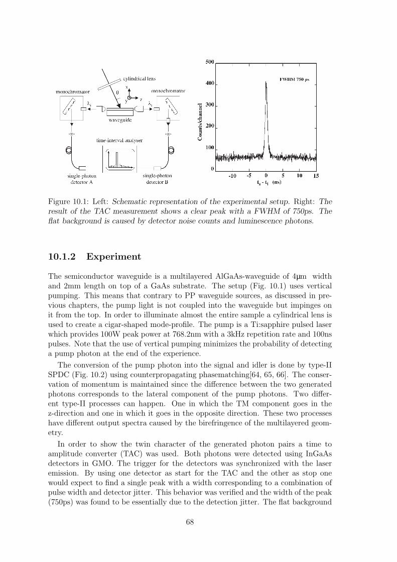
Figure 10.1: Left: Schematic representation of the experimental setup. Right: Theresult of the TAC measurement shows a clear peak with a FWHM of 750ps. Theflat background is caused by detector noise counts and luminescence photons.
10.1.2 Experiment
The semiconductor waveguide is a multilayered AlGaAs-waveguide of 4µm widthand 2mm length on top of a GaAs substrate. The setup (Fig. 10.1) uses verticalpumping. This means that contrary to PP waveguide sources, as discussed in pre-vious chapters, the pump light is not coupled into the waveguide but impinges onit from the top. In order to illuminate almost the entire sample a cylindrical lens isused to create a cigar-shaped mode-profile. The pump is a Ti:sapphire pulsed laserwhich provides 100W peak power at 768.2nm with a 3kHz repetition rate and 100nspulses. Note that the use of vertical pumping minimizes the probability of detectinga pump photon at the end of the experience.
The conversion of the pump photon into the signal and idler is done by type-IISPDC (Fig. 10.2) using counterpropagating phasematching[64, 65, 66]. The conser-vation of momentum is maintained since the difference between the two generatedphotons corresponds to the lateral component of the pump photons. Two differ-ent type-II processes can happen. One in which the TM component goes in thez-direction and one in which it goes in the opposite direction. These two processeshave different output spectra caused by the birefringence of the multilayered geom-etry.
In order to show the twin character of the generated photon pairs a time toamplitude converter (TAC) was used. Both photons were detected using InGaAsdetectors in GMO. The trigger for the detectors was synchronized with the laseremission. By using one detector as start for the TAC and the other as stop onewould expect to find a single peak with a width corresponding to a combination ofpulse width and detector jitter. This behavior was verified and the width of the peak(750ps) was found to be essentially due to the detection jitter. The flat background
68
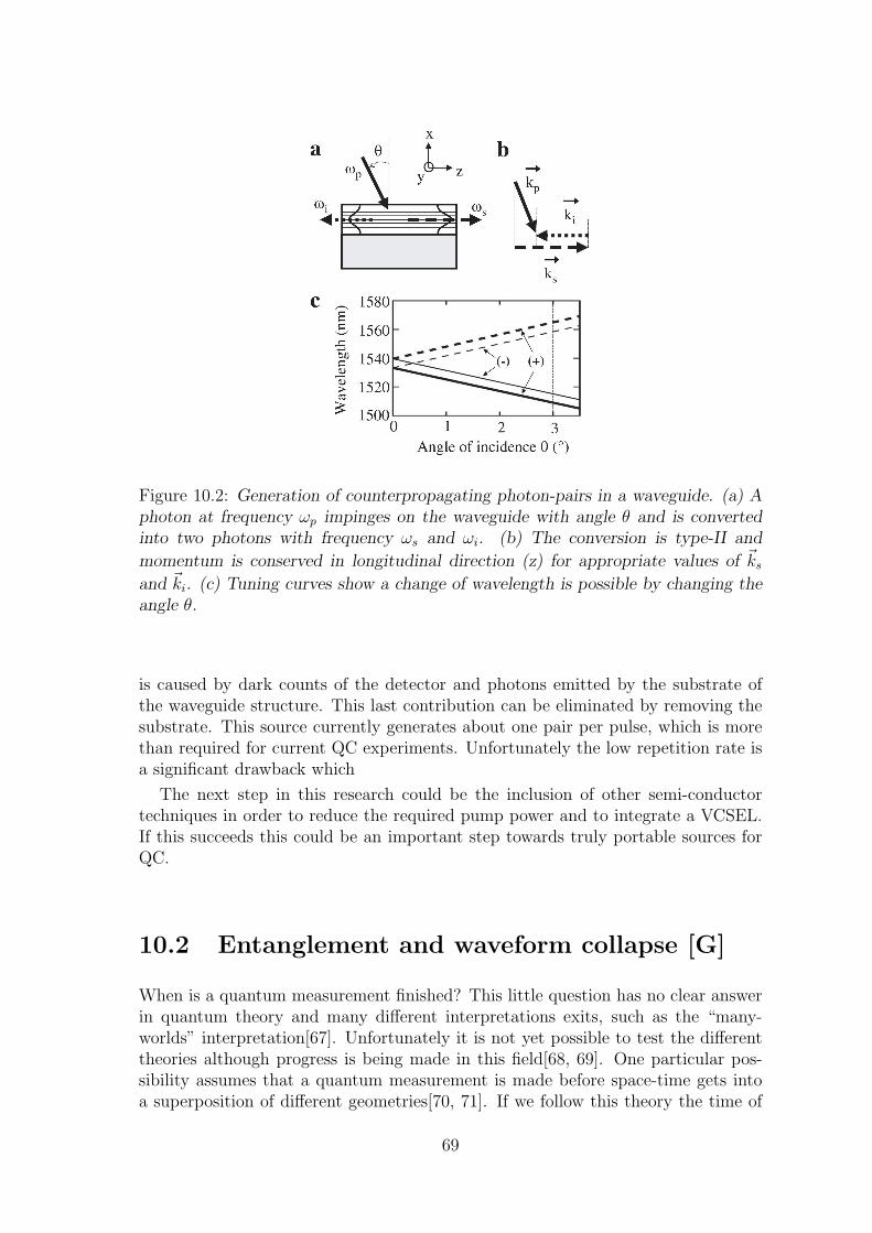
Figure 10.2: Generation of counterpropagating photon-pairs in a waveguide. (a) Aphoton at frequency ωp impinges on the waveguide with angle θ and is convertedinto two photons with frequency ωs and ωi. (b) The conversion is type-II and
momentum is conserved in longitudinal direction (z) for appropriate values of ~ks
and ~ki. (c) Tuning curves show a change of wavelength is possible by changing theangle θ.
is caused by dark counts of the detector and photons emitted by the substrate ofthe waveguide structure. This last contribution can be eliminated by removing thesubstrate. This source currently generates about one pair per pulse, which is morethan required for current QC experiments. Unfortunately the low repetition rate isa significant drawback which
The next step in this research could be the inclusion of other semi-conductortechniques in order to reduce the required pump power and to integrate a VCSEL.If this succeeds this could be an important step towards truly portable sources forQC.
10.2 Entanglement and waveform collapse [G]
When is a quantum measurement finished? This little question has no clear answerin quantum theory and many different interpretations exits, such as the “many-worlds” interpretation[67]. Unfortunately it is not yet possible to test the differenttheories although progress is being made in this field[68, 69]. One particular pos-sibility assumes that a quantum measurement is made before space-time gets intoa superposition of different geometries[70, 71]. If we follow this theory the time of
69

Figure 10.3: Experimental setup used for Bell-test.
collapse of the wavefunction is given by:
tD =3~V
2πGm2d2(10.1)
where G is the gravitational constant and m is the mass of an object with volumeV that moved a distance d. According to this theory the measurement of a photondoesn’t provide a rapid collapse of the wavefunction since it only involves movementof tiny masses (electrons). This leads to the conclusion that none of the Bell-testdone to date involved space-like separated events[72].
An experiment can be done to close this loophole. By moving a significant massevery time a detector finds a click the wavefunction can be forced to collapse rapidly.If the two collapses happen space-like separated there can be no communicationslower or at light speed between both parties. We performed such an experimentwere the mass was a small mirror (m = 2mg, V = 0.9mm3) moved by a piezoactuator (d = 15nm). The scheme of the experiment (Fig. 10.3) shows a continuouswave single mode diode laser, with a power of 2.7mW and a wavelength of 785.2nm,used to pump a PPLN-waveguide. The photon-pairs created here are coupled intoa SMF and the pump is removed using a Si-filter. The photon pairs are separatedusing two FBGs with a width of 1nm and two circulators. One photon is sentapproximately east towards a town called Jussy (17.5km of fiber, 10.7km distance)and the other towards Satigny (13.4km fiber plus 4.1km of fiber on a spool, 8.2kmdistance). At each of these locations there is an unbalanced interferometer with apath length difference of 1.3ns. After the interferometers the photons are detectedusing InGaAs APDs triggered by a synchronization signal coming from the lab inGeneva. Wherever there is a click in an APD a signal is sent to the local piezowhich moves the mass. The phase of one of the interferometers was scanned byscanning its temperature. The resulting interference fringes(Fig. 10.4) shows a rawvisibility V = 0.905 ± 0.015 which clearly violates the Bell-inequality (V ≤ 1√
2).
This experiment therefore closes the locality loophole even if we assume a quantum
70
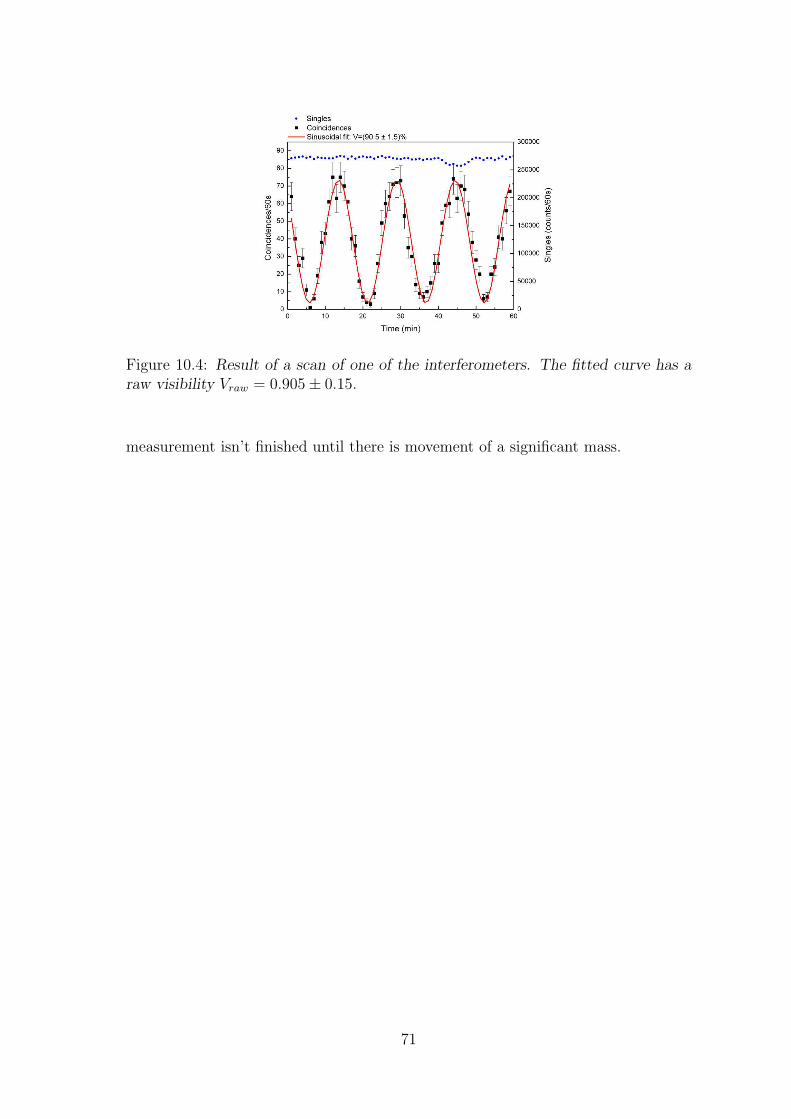
Figure 10.4: Result of a scan of one of the interferometers. The fitted curve has araw visibility Vraw = 0.905± 0.15.
measurement isn’t finished until there is movement of a significant mass.
71


73
Chapter 11
Conclusions
In conclusion we presented several experiments aiming towards the realization ofquantum communication protocols such as a quantum relay in a real world situ-ation outside the lab. In order to allow this timebin encoding was used for ourqubits because of its robustness and photons at telecommunications wavelengths asa medium due to their capability to travel large distances in optical fibers.
In this thesis we first described an entanglement swapping experiment performedinside the laboratory. Its success (V = 0.80 ± 0.04) showed that the techniquesdeveloped might also work for out of the lab experiments. In order to demonstratethe long distance capability of this experiment 2 ∗ 1.1km of standard single modeoptical fiber were used.
After this experiment we tested a new type of Bell-tate analyzer. Instead ofmeasuring only one Bell-state the new method is capable of measuring three Bell-states, albeit probabilistically. The results of this teleportation experiment prove thefunctioning of the analyzer. For out-of-the-lab experiments the system doesn’t haveenough benefits to outweigh the additional losses which are unavoidable in its use.Fundamentally this experiment is interesting since it tested timebin teleportationwith different Bell states. Furthermore there might be protocols for which it isinteresting to measure multiple Bell states.
Following this experiment we performed the first teleportation experiment outsidethe laboratory in which there was distribution of the entangled pair prior to thecreation of the qubit. This is more proof showing that our techniques are robustenough to work independently outside the lab. The only factor of this experimentwhich makes it unscalable to a multi-location quantum relay is the fact that a singlelaser source was used.
As a next step we investigated the possibilities of using multiple laser sources.In order to create sufficient tolerance against jitter and path length fluctuationswe created pulsed sources of photon-pairs with narrow bandwidths. The coherencelength of these photons is of the order of several cm which makes these sourcesinteresting for future experiments.
Some other contributions made during this thesis involved the testing of newsources of photon-pairs in semiconductor waveguides. These sources might one daybe used as small integrated sources for many entanglement experiments. Further-

more work was done on fundamental test of physics by performing Bell-tests withmoving masses and by setting a high lower bound on the hypothetical speed ofquantum information in all possible reference frames.
11.1 Outlook
The work done for this thesis is a step towards the realization of a true quantumrepeater with multiple locations capable of creating entangled states separated byvery large distances. Once such an experiment is done that would be an importantmilestone for the field of quantum communication. It would mean that the realiza-tion of a global quantum web would merely be a question of economic forces andpolitical will. Also it will allow truly private communications around the world thatare provably secure.
74

Resume Francais
Le debut de la physique quantique se trouve dans les premieres annees du vingtiemesiecle. Max Planck avait decouvert qu’on pouvait expliquer le spectre emis par unesource thermique en postulant des quanta d’energie. Albert Einstein a ensuite aussiutilise cette idee pour expliquer l’effet photo-electrique avec des quanta de lumiere,aujourd’hui connus sous le nom de photons.
Dans les dernieres decennies l’interet des physiciens pour la physique quantique agrandi au-dela d’un interet purement fondamental. Une nouvelle idee, introduite parS. Wiesner, etait d’utiliser les proprietes typiquement quantiques comme ressource.Cette idee a pris des ailes quand P. Shor a decouvert un algorithme quantique pourfactoriser des nombres premiers. Depuis cette idee s’est developpee dans une nouvelleavenue de recherche: la communication et l’informatique quantique.
L’informatique quantique est le terrain de recherche qui utilise les proprietesquantique pour faire des ordinateurs quantiques ou encore des simulations quan-tiques. L’algorithme de Shor mentionne ci-dessus est l’algorithme qui explique lemieux l’interet de ces ordinateurs. En effet, par ce nouvel algorithme il est possiblede factoriser une grand chiffre N en ses facteurs premiers. Sur un ordinateur clas-sique cette operation est tres difficile et prends un temps exponentiel par rapport ala largeur du chiffre. Avec l’algorithme de Shor il est possible de faire la meme tachesur un ordinateur quantique dans un temps polynomial. Cette possibilite aura desconsequences enormes sur les methodes de cryptographie actuelle.
La communication quantique sert a distribuer des etats quantiques entre plusieursendroits. Ceci sera requis pour un reseau quantique le jour ou les ordinateurs quan-tiques seront communs. Dans une periode moins lointaine, il est possible de faire dela distribution quantique de clefs. Ceci permet a deux lieus de partager une serie desbits aleatoires en secret. Combine avec l’encodage a masque jetable (aussi appelechiffre de Vernam ou, plus communement en anglais, “one-time pad”) ceci donneune forme de cryptographie absolument sure et inviolable.
A premiere vue on pourrait s’imaginer qu’il est simple de distribuer un etatquantique. On prend un photon, on le mets dans l’etat desire et on l’envoie par unefibre optique. On attends que le photon arrive de l’autre cote et voila, l’etat a etedistribue. Malheureusement des methodes aussi simples ne fonctionnent pas pourdes distance qui nous interesse a cause des pertes dans les fibres optiques. Pourla communication classique ceci n’est pas un probleme car il suffit de mettre desamplificateurs de signaux dans le chemin. Pour les etats quantiques par contre unetelle amplification est malheureusement impossible. Ceci peut etre demontre par letheoreme de non-clonage.
75
Il y a une solution a ce probleme. Il est possible d’utiliser un repeteur quantique.Dans un repeteur les etats quantiques ne sont pas amplifies mais teleportes vers leurdestination finale. Utiliser plusieurs repeteurs en serie permet de franchir de grandesdistances. Pendant cette these plusieurs experiences ont ete faites pour tester lespossibilites de fabriquer un repeteur quantique.
Premierement, nous avons fait une experience de teleportation d’intrication. L’intricationest la propriete qu’ont deux etats quantique de ne pas pouvoir etre decrits separement.Nous avons reussi a teleporter cette propriete d’un photon a un autre. Ce faisant,nous avons cree la situation tres contre-intuitive ou deux photons sans aucune his-toire commune ne peuvent etre decrits qu’ensemble.
Notre experience a utilise des photons aux longueurs d’onde utilisees par lescompagnies de telecommunications et en codage temporel. Cette combinaison enfait un systeme ideal pour atteindre des longues distances. Notre experience amontre une teleportation d’intrication sur une distance de 2.2 km de fibre optiqueen laboratoire.
Ensuite, nous avons etudie et developpe une nouvelle methode pour faire desmesures des Bell, la partie le plus importante d’un protocole de teleportation.Jusqu’ici, tous les systemes pour faire ces mesures ont ete partiels. En general iln’est possible de detecter que 2 des 4 etats de Bell. Nous avons developpe un systemequi permet de mesurer 3 des 4 etats de Bell. Pour montrer le fonctionnement de cesysteme nous l’avons utilise dans une experience de teleportation.
Apres avoir compris et maitrise toutes ces techniques, nous avons fait la premiereexperience de teleportation hors du laboratoire qui distribue les etats intriquee avantde creer le qubit a teleporter. Nous avons fait ceci sur une distance de 800m, entrenotre laboratoire et une station de relais de Swisscom. Cette experience a finalementprouve que les techniques que nous avons developpes sont suffisamment robustespour fonctionner hors du labo. Le seul defaut de cette experience est que les deuxsources de photons etaient encore pompees par le meme laser.
La derniere experience de cette these essaie d’adresser le probleme des paires dephoton toujours crees au meme endroit. Nous utilisons un systeme de deux lasersindependants dans une configuration Maıtre-Esclave. Le signal d’horloge du maıtreest envoye avec une fibre optique et il est donc possible de vraiment separer les deuxsources. Pour avoir une bonne tolerance contre la gigue des signaux optiques et leschangements de longueur de chemin nous utilisons des filtres tres fin pour avoir desphotons a large bande. Pour montrer le fonctionnement de nos sources nous avonsfait une experience d’agglomeration de photons.
Des resultats de toutes les experiences faites pendant cette these nous pouvonsconclure que nos techniques sont tres utiles pour des experiences de teleportationhors des laboratoires. Nous avons commence le chemin pour faire un veritable relaisquantique dans le futur.
76
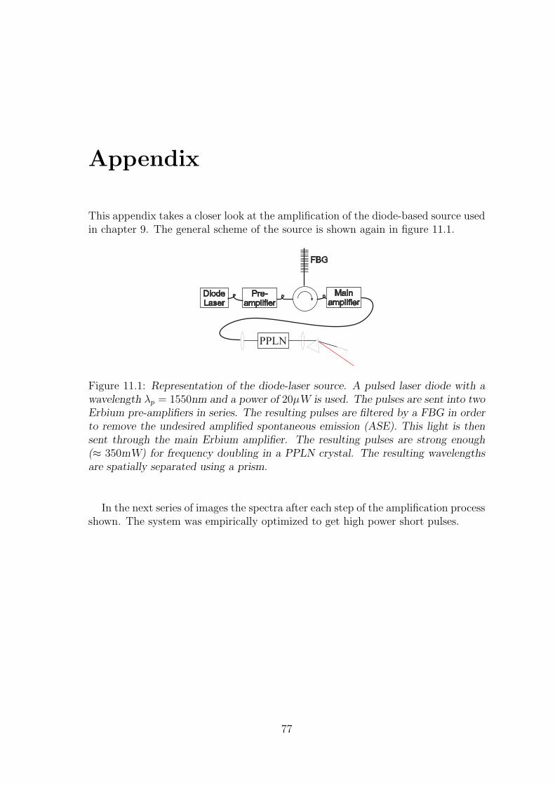
Appendix
This appendix takes a closer look at the amplification of the diode-based source usedin chapter 9. The general scheme of the source is shown again in figure 11.1.
DiodeLaser
Pre-amplifier
Mainamplifier
FBG
PPLN
Figure 11.1: Representation of the diode-laser source. A pulsed laser diode with awavelength λp = 1550nm and a power of 20µW is used. The pulses are sent into twoErbium pre-amplifiers in series. The resulting pulses are filtered by a FBG in orderto remove the undesired amplified spontaneous emission (ASE). This light is thensent through the main Erbium amplifier. The resulting pulses are strong enough(≈ 350mW) for frequency doubling in a PPLN crystal. The resulting wavelengthsare spatially separated using a prism.
In the next series of images the spectra after each step of the amplification processshown. The system was empirically optimized to get high power short pulses.
77

1549.5 1550.0 1550.5 1551.0 1551.5 1552.01E-9
1E-8
1E-7
1E-6 1550.96P
ower
(W)
wavelength (nm)
output PicoQuant laser1550.968.7E-7
x87
Figure 11.2: Spectrum of the diode-laser
1520 1540 15601E-8
1E-7
1E-6
1E-5
1E-4
1E-3
1535.8 1550.9
Pow
er(m
)
Wavelength (nm)
After 1st Amplifier
1.2E-4
1.5E-5
x8
9.9E-7
x121
Figure 11.3: Spectrum after the first Erbium pre-amplifier. The small peak is theamplification of the signal coming from the diode laser. The background is causedby amplified spontaneous emission (ASE). There is a lot more power in the ASEthen in the main peak.
78

1520 1525 1530 1535 1540 1545 1550 1555 1560 1565 1570 15751E-8
1E-7
1E-6
1E-5
1E-4
1E-3
1550.0 1550.5 1551.0 1551.5 1552.01E-6
1E-5
1E-4
1E-31550.888
Pow
er (m
W)
wavelength (nm)
After 2nd Amplifier, Before FBG
6.5E-4
7.9E-5
x8.2
4.3E-6
x151
Figure 11.4: Spectrum after the second Erbium pre-amplifier. The amplified pulsesare well above the level of ASE.
1520 1530 1540 1550 1560 1570 15801E-8
1E-7
1E-6
1E-5
1E-4
1E-3
1550.0 1550.5 1551.0 1551.5
1E-6
1E-5
1E-4
1E-31550.514
Pow
er (m
W)
wavelength (nm)
After FBG7.9E-4
3.3E-5
x24
1.8E-6
x438
x151
350 pm
6.35E-4
1..51E-4
x4.2
Figure 11.5: Spectrum after the FBG. The level of ASE is reduced and a small partof the amplified emission is selected.
79

1530 1535 1540 1545 1550 1555 1560 1565 1570 1575 15801E-7
1E-6
1E-5
1E-4
1E-3
0.01
0.1
1550.5 1551.0 1551.5
0.01
0.1
1550.42
1550.761550.96
After 3th Amplifier, Before PPLN
Pow
er (w
)
Wavelength (nm)
6.5E-5
x307
2E-2
340 pm 200 pm
4.3E-2
3.5E-1
x 8.1
Figure 11.6: Final spectrum after the main Erbium amplifier. One powerful peakwith some fine structure.
774.5 775.0 775.5 776.0 776.5 777.0 777.51E-6
1E-5
1E-4
1E-3
775.5 775.8 776.1
1E-3
775.7974
776.0836
Pow
er (W
)
Wavelength
1+1 1+3
1.8E-3
3.3E-4
x5.45
280 pm
Figure 11.7: Example of the spectrum after the conversion in the PPLN. The struc-ture of this final spectrum depends heavily on the setting of the FBG.
80

Bibliography
[1] “Genesis 1:1-3.”
[2] M. Planck, “Zur Theorie des Gesetzes der Energieverteilung im Normalspek-trum,” Verhandl. Deutsch. phys. Ges., vol. 2, p. 237, 1900.
[3] A. Einstein, “Uber einen die Erzeugung und Verwandlung des Lichts betref-fenden heuristischen Gesichtspunkt,” Ann. Phys., vol. 17, pp. 132–148, 1905.
[4] G. N. Lewis, “The conservation of photons,” Nature, vol. 118,, p. 874–875, 1926.
[5] S. J. Wiesner, “Conjugate coding,” ACM SIGACT News, vol. 15, p. 1, 1983.
[6] W. K. Wootters and W. H. Zurek, “A single quantum cannot be cloned,” Na-ture, vol. 299, pp. 802–803, Oct. 1982.
[7] P. Shor, “Polynomial-time algorithm for prime factorization and discrete loga-rithms on a quantum computer,” SIAM J. Sci. Statis. Comput., vol. 26, p. 1484,1997. quant-ph/9508027.
[8] D. S. Abrams and S. Lloyd, “Simulation of many-body fermi systems on auniversal quantum computer,” Phys. Rev. Lett., vol. 79, pp. 2586–2589, Sep1997.
[9] C. Bennett and G. Brassard, “Quantum cryptography: Public-key distribu-tion and coin tossing,” in Proceedings of the IEEE International Conferenceon Computers, Systems and Signal Processing, Bangalore, India, (New York),pp. 175–179, IEEE, 1984.
[10] G. Vernam, “Cipher printing telegraph systems for secret wire and radio tele-graphic communications,” J. Am. Inst. Electr. Eng., vol. 55, p. 109, 1926.
[11] C. Bennett, G. Brassard, C. Crepeau, R. Jozsa, A. Peres, and W. W.K., “Tele-porting an unknown quantum state via dual classical and einstein-podolsky-rosen channels,” Phys. Rev. lett., vol. 70, p. 1895, 1993.
[12] D. Bouwmeester, J.-W. Pan, K. Mattle, M. Eibl, H. Weinfurter, andA. Zeilinger, “Experimental quantum teleportation,” Nature, vol. 390, pp. 575–579, Dec. 1997.
81
[13] I. Marcikic, H. de Riedmatten, W. Tittel, H. Zbinden, and N. Gisin, “Long-distance teleportation of qubits at telecommunication wavelengths,” Nature,vol. 421, pp. 509–513, Jan. 2003.
[14] J.-W. Pan, D. Bouwmeester, H. Weinfurter, and A. Zeilinger, “Experimentalentanglement swapping: Entangling photons that never interacted,” Phys. Rev.Lett., vol. 80, pp. 3891–3894, 1998.
[15] L.-M. Duan, M. Lukin, J. Cirac, and P. Zoller, “Long-distance quantum com-munication with atomic ensembles and linear optics,” Nature, vol. 414, pp. 413–418, 2001.
[16] B. Schumacher, “Quantum coding,” Phys. Rev. A, vol. 51, pp. 2738–2747, 1995.
[17] D. Loss and D. P. DiVincenzo, “Quantum computation with quantum dots,”Phys. Rev. A, vol. 57, pp. 120–126, Jan 1998.
[18] C. Monroe, D. M. Meekhof, B. E. King, W. M. Itano, and D. J. Wineland,“Demonstration of a fundamental quantum logic gate,” Phys. Rev. Lett., vol. 75,pp. 4714–4717, Dec 1995.
[19] L.-M. Duan and C. Monroe, “Robust quantum information processing withatoms, photons, and atomic ensembles,” Advances in Atomic, Molecular, andOptical Physics, vol. 55, pp. 419–464, 2008.
[20] T. Jennewein, C. Simon, G. Weihs, H. Weinfurter, and A. Zeilinger, “Quantumcryptography with entangled photons,” Phys. Rev. Lett., vol. 84, pp. 4729–4732,May 2000.
[21] D. S. Naik, C. G. Peterson, A. G. White, A. J. Berglund, and P. G. Kwiat,“Entangled state quantum cryptography: Eavesdropping on the ekert proto-col,” Phys. Rev. Lett., vol. 84, pp. 4733–4736, May 2000.
[22] J. Gordon and H. Kogelnik Proc Natl Acad Sci U S A, vol. 97(9), pp. 4541––4550, 2000.
[23] I. L. Chuang and Y. Yamamoto, “Simple quantum computer,” Phys. Rev. A,vol. 52, pp. 3489–3496, Nov 1995.
[24] J. Brendel, N. Gisin, W. Tittel, and H. Zbinden, “Pulsed energy-time entan-gled twin-photon source for quantum communication,” Phys Rev. Lett., vol. 82,p. 2594, 1999.
[25] R. T. Thew, A. Acın, H. Zbinden, and N. Gisin, “Bell-type test of energy-timeentangled qutrits,” Phys. Rev. Lett., vol. 93, p. 010503, Jul 2004.
[26] D. Stucki, H. Zbinden, and N. Gisin, “A Fabry Perot-like two-photon interfer-ometer for high-dimensional time-bin entanglement,” Journal of Modern Op-tics, vol. 52, pp. 2637–2648, May 2005.
82

[27] P. Michler, A. Kiraz, C. Becher, W. V. Schoenfeld, P. M. Petroff, L. Zhang,E. Hu, and A. Imamoglu, “A Quantum Dot Single-Photon Turnstile Device,”Science, vol. 290, no. 5500, pp. 2282–2285, 2000.
[28] C. Kurtsiefer, S. Mayer, P. Zarda, and H. Weinfurter, “Stable solid-state sourceof single photons,” Phys. Rev. Lett., vol. 85, pp. 290–293, Jul 2000.
[29] Y. H. Shih and C. O. Alley, “New type of einstein-podolsky-rosen-bohm exper-iment using pairs of light quanta produced by optical parametric down conver-sion,” Phys. Rev. Lett., vol. 61, pp. 2921–2924, Dec 1988.
[30] S. Tanzilli, H. De Riedmatten, W. Tittel, H. Zbinden, P. Baldi, M. De Micheli,D. Ostrowsky, and N. Gisin, “Highly efficient photon-pair source using period-ically poledlithium niobate waveguide,” Elec. Lett., vol. 37, pp. 26–28, 2001.
[31] M. Fiorentino, P. Voss, J. Sharping, and P. Kumar, “All-fiber photon-pairsource for quantum communications,” Photonics Technology Letters, vol. 14,pp. 983–985, 2002.
[32] S. Tanzilli, W. Tittel, M. Halder, O. Alibart, P. Baldi, N. Gisin, and H. Zbinden,“A photonic quantum information interface,” Nature, vol. 437, pp. 116–120,Sept. 2005.
[33] R. T. Thew, D. Stucki, J.-D. Gautier, H. Zbinden, and A. Rochas, “Free-running ingaas/inp avalanche photodiode single photon counting at telecomwavelengths,” Phys. Lett., vol. 91, p. 201114, 2007.
[34] “id-quantique photon counting module id200/id201, www.idquantique.com.”
[35] G. Ribordy, J.-D. Gautier, H. Zbinden, and N. Gisin, “Performance of ingaasinp avalanche photodiodes as gated-mode photon counters,” Appl.Opt., vol. 37,pp. 2272–2277, 1998.
[36] R. T. Thew, S. Tanzilli, L. Krainer, S. C. Zeller, A. Rochas, I. Rech, S. Cova,H. Zbinden, and N. Gisin, “Low jitter up-conversion detectors for telecom wave-length ghz qkd,” New. J. Phys, vol. 8, p. 32, 2006.
[37] S. Somani, S. Kasapi, K. Wilsher, W. Lo, R. Sobolewski, and G. Gol’tsman,“New photon detector for device analysis: Superconducting single-photon de-tector based on a hot electron effect,” Journal of Vacuum Science & TechnologyB: Microelectronics and Nanometer Structures, vol. 19, pp. 2766–2769, 2001.
[38] G. N. Gol’tsman, O. Okunev, G. Chulkova, A. Lipatov, A. Semenov,K. Smirnov, B. Voronov, A. Dzardanov, C. Williams, and R. Sobolewski, “Pi-cosecond superconducting single-photon optical detector,” Applied Physics Let-ters, vol. 79, no. 6, pp. 705–707, 2001.
[39] A. Korneev, Y. Vachtomin, O. Minaeva, A. Divochiy, K. Smirnov, O. Okunev,G. Gol’tsman, C. Zinoni, N. Chauvin, L. Balet, F. Marsili, D. Bitauld, B. Al-loing, L. Li, A. Fiore, L. Lunghi, A. Gerardino, M. Halder, C. Jorel, and
83

H. Zbinden, “Single-photon detection system for quantum optics applications,”Selected Topics in Quantum Electronics, vol. 13, pp. 944–951, 2007.
[40] A. Einstein, B. Podolsky, and N. Rosen, “Can quantum-mechanical descriptionof physical reality be considered complete?,” Phys. Rev., vol. 47, pp. 777–780,1935.
[41] J. Bell, “On the Einstein-Podolsky-Rosen paradox,” Physics, vol. 1, pp. 195–200, 1964.
[42] J. F. Clauser, M. A. Horne, A. Shimony, and R. A. Holt, “Proposed experimentto test local hidden-variable theories,” Phys. Rev. Lett., vol. 23, pp. 880–, Oct.1969.
[43] T. Jennewein, G. Weihs, J.-W. Pan, and A. Zeilinger, “Experimental nonlo-cality proof of quantum teleportation and entanglement swapping,” Phys. Rev.Lett., vol. 88, pp. 017903–4, Jan. 2002.
[44] F. e. a. Sciarrino Phys Rev. A, vol. 66, p. 024309, 2002.
[45] R. E. S. Polkinghorne and T. C. Ralph, “Continuous variable entanglementswapping,” Phys. Rev. Lett., vol. 83, pp. 2095–2099, Sep 1999.
[46] N. Takei, H. Yonezawa, T. Aoki, and A. Furusawa, “High-fidelity teleporta-tion beyond the no-cloning limit and entanglement swapping for continuousvariables,” Physical Review Letters, vol. 94, no. 22, p. 220502, 2005.
[47] C. K. Hong, Z. Y. Ou, and L. Mandel, “Measurement of subpicosecond timeintervals between two photons by interference,” Phys. Rev. Lett., vol. 59,pp. 2044–2046, Nov 1987.
[48] C. H. Bennett and S. J. Wiesner, “Communication via one- and two-particle op-erators on einstein-podolsky-rosen states,” Phys. Rev. Lett., vol. 69, pp. 2881–2884, 1992.
[49] K. Mattle, H. Weinfurter, P. G. Kwiat, and A. Zeilinger, “Dense coding inexperimental quantum communication,” Phys. Rev. Lett., vol. 76, pp. 4656–,June 1996.
[50] H. Weinfurther, “Experimental bell-state analysis,” Europhysics Letters,vol. 25, pp. 559–564, 1994.
[51] J. Calsamiglia and N. Lutkenhaus, “Maximum efficiency of a linear-optical bell-state analyzer,” Applied Physics B: Lasers and Optics, vol. 72, pp. 67–71, Jan.2001.
[52] E. Knill, R. Laflamme, and G. J. Milburn, “A scheme for efficient quantumcomputation with linear optics,” Nature, vol. 409, pp. 46–52, Jan. 2001.
[53] Y.-H. Kim, S. P. Kulik, and Y. Shih, “Quantum teleportation of a polariza-tion state with a complete bell state measurement,” Phys. Rev. Lett., vol. 86,pp. 1370–1373, 2001.
84
[54] F. Grosshans and P. Grangier, “Quantum cloning and teleportation criteria forcontinuous quantum variables,” Phys. Rev. A, vol. 64, p. 010301, 2001.
[55] D. Bruss, “Optimal eavesdropping in quantum cryptography with six states,”Phys. Rev. Lett., vol. 81, pp. 3018–3021, 1998.
[56] R. Ursin, T. Jennewein, M. Aspelmeyer, R. Kaltenbek, M. Lindenthal,P. Walther, and A. Zeilinger, “Quantum teleportation across the danube,” Na-ture, vol. 430, p. 849, 2004.
[57] T. Yang, Q. Zhang, T.-Y. Chen, S. Lu, J. Yin, J.-W. Pan, Z.-Y. Wei, J.-R.Tian, and J. Zhang, “Experimental synchronization of independent entangledphoton sources,” Phys. Rev. Lett., vol. 96, pp. 110501–4, Mar. 2006.
[58] H. de Riedmatten, I. Marcikic, W. Tittel, H. Zbinden, D. Collins, and N. Gisin,“Long distance quantum teleportation in a quantum relay configuration,” Phys.Rev. Lett., vol. 92, p. 047904, 2004.
[59] R. Kaltenbaek, B. Blauensteiner, M. Zukowski, M. Aspelmeyer, andA. Zeilinger, “Experimental interference of independent photons,” Phys. Rev.Lett., vol. 96, pp. 240502–4, June 2006.
[60] W. Tittel, J. Brendel, N. Gisin, and H. Zbinden, “Long-distance bell-type testsusing energy-time entangled photons,” Phys. Rev. A, vol. 59, pp. 4150–4163,1999.
[61] M. Halder, A. Beveratos, T. Thew, C. Jorel, H. Zbinden, and N. Gisin, “Highcoherence photon pair source for quantum communication,” New J. Phys. 10(2008) 023027, vol. 10, p. 023027, 2008.
[62] M. Zukowski, A. Zeilinger, and H. Weinfurter, “Entangling photons radiatedby independent pulsed sources,” Fundamental Problems in Quantum Theory,vol. 755, p. 91, 1995.
[63] H. de Riedmatten, I. Marcikic, W. Tittel, H. Zbinden, and N. Gisin, “Quantuminterference with photon pairs created in spatially separated sources,” Phy. Rev.A, vol. 67, p. 022301, 2003.
[64] Y. J. Ding, S. J. Lee, and J. B. Khurgin, “Transversely pumped counter-propagating optical parametric oscillation and amplification,” Phys. Rev. Lett.,vol. 75, pp. 429–432, Jul 1995.
[65] A. De Rossi and V. Berger, “Counterpropagating twin photons by parametricfluorescence,” Phys. Rev. Lett., vol. 88, p. 043901, Jan 2002.
[66] M. C. Booth, M. Atature, G. Di Giuseppe, B. E. A. Saleh, A. V. Sergienko, andM. C. Teich, “Counterpropagating entangled photons from a waveguide withperiodic nonlinearity,” Phys. Rev. A, vol. 66, p. 023815, Aug 2002.
[67] H. Everett, “”relative state” formulation of quantum mechanics,” Rev. Mod.Phys., vol. 29, 1957.
85

[68] B. Brezger, L. Hackermuller, S. Uttenthaler, J. Petschinka, M. Arndt, andA. Zeilinger, “Matter-wave interferometer for large molecules,” Phys. Rev. Lett.,vol. 88, p. 100404, Feb 2002.
[69] W. Marshall, C. Simon, R. Penrose, and D. Bouwmeester, “Towards quantumsuperpositions of a mirror,” Phys. Rev. Lett., vol. 91, p. 130401, Sep 2003.
[70] L. Diosi, “A universal master equation for the gravitational violation of quan-tum mechanics,” hysics Letters A, vol. 120, pp. 377–381, 1987.
[71] S. Adler, “Comments on proposed gravitational modifications of schrodingerdynamics and their experimental implications,” J. Phys. A, vol. 40, p. 755,2007.
[72] A. Kent, “A proposed test of the local causality of spacetime,” gr-qc/0507045v2,2005.
86

Publication list
[A] H. de Riedmatten, I. Marcikic, J.A.W. van Houwelingen, W. Tittel, H. Zbinden,and N. Gisin, Long-distance entanglement swapping with photons from seper-ated sources, Physical Review A 71, 050302(R) (2005)
[B] J.A.W. van Houwelingen, N. Brunner, A. Beveratos, H. Zbinden, and N. Gisin,Quantum Teleportation with a 3-Bell-state Analyzer, Physical Review Letters96, 130502 (2006)
[C] J.A.W. van Houwelingen, N. Brunner, A. Beveratos, H. Zbinden, and N. Gisin,Experimental quantum teleportation with a three-Bell-state analyzer, PhysicalReview A 74, 022303 (2006)
[D] O. Landry, J.A.W. van Houwelingen, A. Beveratos, H. Zbinden, and N. Gisin,Quantum teleportation over the Swisscom telecommunication network, Journalof the Optical Society of America 24-2, 398 (2007)
[E] J.A.W. van Houwelingen, O. Landry, A. Beveratos, H. Zbinden, and N. Gisin,Synchronized and independent picosecond photon sources for quantum commu-nication experiments, To be submitted
[F] L. Lanco, S. Ducci, J.-P. Likforman, X. Marcadet ,J.A.W. van Houwelingen,H. Zbinden, G. Leo and V. Berger, Semiconductor waveguide source of coun-terpropagating twin photons, Physical Review Letters 97, 173901(2006)
[G] D. Salart, A. Baars, J.A.W. van Houwelingen, H. Zbinden, and N. Gisin,Space-like Separation in a Bell Test with Gravitationally Induced Collapses,To be submitted
87


Newspaper articles
In the next few pages some newspaper clippings about the teleportation experimentbetween our lab and the Swisscom station at Plainpalais are shown. These wereadded here as an illustration that it is possible to interest a general public for thekind of research done in this thesis. Despite our efforts the articles contain a fewerrors but that seems unavoidable when popularizing this subject.
[P1] Newspaper article, Premiere teleportation quantique dans un environement de¡¡monde reel¿¿, Tribune de Geneve, (17-18 juin 2006)
89

[P2] Newspaper article, Le teleportation fait une pas vers le monde reel, 24 Heures,(16 juin 2006)
90

[P3] Newspaper article, Les physiciens font entrer dans le ‘monde reel’ la telepor-tation quantique, Le Temps, (16 juin 2006)
91


Publications
93
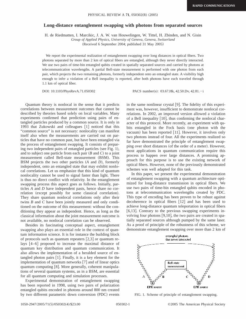
Long-distance entanglement swapping with photons from separated sources
H. de Riedmatten, I. Marcikic, J. A. W. van Houwelingen, W. Tittel, H. Zbinden, and N. GisinGroup of Applied Physics, University of Geneva, Geneva, Switzerland
sReceived 6 September 2004; published 31 May 2005d
We report the experimental realization of entanglement swapping over long distances in optical fibers. Twophotons separated by more than 2 km of optical fibers are entangled, although they never directly interacted.We use two pairs of time-bin entangled qubits created in spatially separated sources and carried by photons attelecommunication wavelengths. A partial Bell-state measurement is performed with one photon from eachpair, which projects the two remaining photons, formerly independent onto an entangled state. A visibility highenough to infer a violation of a Bell inequality is reported, after both photons have each traveled through1.1 km of optical fiber.
DOI: 10.1103/PhysRevA.71.050302 PACS numberssd: 03.67.Hk, 42.50.Dv, 42.81.2i
Quantum theory is nonlocal in the sense that it predictscorrelations between measurement outcomes that cannot bedescribed by theories based solely on local variables. Manyexperiments confirmed that prediction using pairs of en-tangled particles produced by a common source. It is only in1993 that Zukowski and colleaguesf1g noticed that this“common source” is not necessary: nonlocality can manifestitself also when the measurements are carried out on par-ticles that have no common past, but have been entangled viathe process of entanglement swapping. It consists of prepar-ing two independent pairs of entangled particlesssee Fig. 1d,and to subject one particle from each pairsB andCd to a jointmeasurement called Bell-state measurementsBSMd. ThisBSM projects the two other particlessA and Dd, formerlyindependent, onto an entangled state that may exhibit nonlo-cal correlations. Let us emphasize that this kind of quantumnonlocality cannot be used to signal faster than light. Thereis thus no direct conflict with relativity. In the entanglementswapping process this aspect goes as follows. Initially, par-ticles A andD have independent pasts, hence share no cor-relation sexcept possibly for some classical correlationd.They share quantum nonlocal correlations only after theirtwins B and C have been jointly measured and only condi-tioned on the outcome of this measurement: without the con-ditioning they appear as independent. Hence, as long as theclassical information about the joint measurement outcome isnot available, no nonlocal correlation can be observed.
Besides its fascinating conceptual aspect, entanglementswapping also plays an essential role in the context of quan-tum information science. It is for instance the building blockof protocols such as quantum repeatersf2,3g or quantum re-lays f4–6g proposed to increase the maximal distance ofquantum key distribution and quantum communication. Italso allows the implementation of a heralded source of en-tangled photon pairsf1g. Finally, it is a key element for theimplementation of quantum networksf7g and of linear opticsquantum computingf8g. More generally, coherent manipula-tions of several quantum systems, as in a BSM, are essentialfor all quantum computing and simulation processes.
Experimental demonstration of entanglement swappinghas been reported in 1998, using two pairs of polarizationentangled qubits encoded in photons around 800 nm createdby two different parametric down conversionsPDCd events
in the same nonlinear crystalf9g. The fidelity of this experi-ment was, however, insufficient to demonstrate nonlocal cor-relations. In 2002, an improved version allowed a violationof a Bell inequalityf10g, thus confirming the nonlocal char-acter of this protocol. More recently, an experiment with qu-bits entangled in the Fock basissone photon with thevacuumd has been reportedf11g. However, it involves onlytwo photons instead of four. All the experiments realized sofar have demonstrated the principle of entanglement swap-ping over short distancessof the order of a meterd. However,most applications in quantum communication require thisprocess to happen over large distances. A promising ap-proach for this purpose is to use the existing network ofoptical fibers. However, none of the previously demonstratedschemes was well adapted for this task.
In this paper, we present the experimental demonstrationof entanglement swapping with a quantum architecture opti-mized for long-distance transmission in optical fibers. Weuse two pairs of time-bin entangled qubits encoded in pho-tons at telecommunication wavelengths created by PDC.This type of encoding has been proven to be robust againstdecoherence in optical fibersf12g and has been used toachieve long-distance quantum teleportation in optical fibersf6,13g. Contrary to the previous swapping experiments in-volving four photonsf9,10g, the two pairs are created in spa-tially separated sources although pumped by the same laser.As a proof of principle of the robustness of this scheme, wedemonstrate entanglement swapping over more than 2 km of
FIG. 1. Scheme of principle of entanglement swapping.
PHYSICAL REVIEW A 71, 050302sRd s2005d
RAPID COMMUNICATIONS
1050-2947/2005/71s5d/050302s4d/$23.00 ©2005 The American Physical Society050302-1

optical fiber. For this purpose, a partial BSM is performedonto one photon from each pair, entangling the two remain-ing photons which have each traveled over separated 1.1 kmspools of optical fiber. Entanglement is verified using a two-photon quantum interference conditioned on a successfulBSM.
Time-bin entangled qubits can be seen as photon pairscreated in a coherent superposition of two emission timeswith a well-defined relative phasef14g. They are created firstby splitting a laser pulse into two subsequent pulses using anunbalanced interferometer called a pump interferometer. Onephoton pair is then created by PDC. The down convertedphotons originate from the two pulses with a relative phased, hence the photon pair quantum state isuf+sddl=c0u0,0l+eidc1u1,1l, where u0, 0l corresponds to a photon pair cre-ated in the early time bin andu1, 1l to a photon pair createdin the delayed time bin, withc0
2+c12=1. In our experiment,
we employ two spatially separated sources of entangled pho-tons. In one of these sources, we create a stateuf+sddlA,B,while in the other one we create a stateuf−sddlC,D= uf+sd+pdlC,D. Initially, the two photon pairs are independent andthe total state can be written as the tensor product:uCABCDl= uf+sddlAB^ uf−sddlCD This state can be rewritten in theform.
uCABCDl =1
2fuf+lBC ^ uf−s2ddlAD + uf−lBC ^ uf+s2ddlAD
+ uc+lBC ^ eiduc−lAD + uc−lBC ^ eiduc+lADg, s1d
where the four Bell states areuf±sddl=1/Î2su0,0l±eidu1,1ld and ucs±dl=1/Î2su1,0l± u0,1ld. When photonsBandC are measured in the Bell basis, i.e., projected onto oneof the four Bell states, photonsA and D are projected ontothe corresponding entangled state. Note that when photonsBand C are projected onto the stateuc+l or uc−l, the state ofphotonsA and D is independent of the phased, which ap-pears only as a global factor. This means that in this case, thecreation process is robust against phase fluctuations in thepump interferometer and pump-laser wavelength driftsf15g.Hence, this experiment can also be considered as aspostse-lectedd heralded source of entangled photon pairs robustagainst phase fluctuation in the preparation stagef16g. If,however, photonsB andC are projected onto the stateuf+lor uf−l the state of photonsA and D depends on twice thephased. In our experiment, we make a partial BSM, lookingonly at projections of photonsB and C onto the uc−l Bellstate. Another interesting feature to note is that all the fourBell states are involved in the experiment, since we startfrom uf+l and uf−l states, and make a projection onto theuc−l state, which projects the two remaining photons onto theuc+l state.
A scheme of our experiment is presented in Fig. 2. Fem-tosecond pump pulses are sent to an unbalanced bulk Mich-elson interferometer with a travel time difference oft=1.2 ns. Thanks to the use of retroreflectors, we can utilizeboth outputs of the interferometer, which are directed to spa-tially separated lithium triboratesLBOd nonlinear crystals.Collinear nondegenerate time-bin entangled photons at tele-
communication wavelengthss1310 and 1550 nmd are even-tually created by PDC in each crystal. Because of the phaseacquired at the beam splitter in the pump interferometer thereis an additional relative phase ofp between the termsu0, 0land u1, 1l in the second output of the interferometer. Thisexplains why a stateuf+sddl is created in one crystal while astateuf−sddl is created in the other one.
The created photons are coupled into single-mode opticalfibers and deterministically separated with a wavelength-division multiplexersWDMd. The two photons at 1310 nmsB andCd are subject to a partial BSM using a standard 50-50fiber beam splitterf17g. It can be shown that whenever pho-tons B and C are detected in different output modes anddifferent time bins, the desired projection ontoucs−dlBC isachievedf18g. For this kind of measurement, the two incom-ing photons must be completely indistinguishable in theirspatial, temporal, spectral, and polarization mode. The indis-tinguishability is verified by a Hong-Ou-Mandel experimentf19,20g. The two photons at 1310 nm are filtered with 5 nmbandwidth interference filterssIFd in order to increase theircoherence time to 500 fs, larger than the pump pulse’s dura-tion s200 fsd, which is necessary in order to make the pho-tons temporally indistinguishablef21g.
The two photons at 1550 nm, filtered to 18 nm bandwidthsA andDd, each travel over 1.1 km of dispersion shifted fibersDSFd. Their entanglement is then analyzed with two fiberMichelson interferometers with the same travel time differ-ence as the pump one. The phase of each interferometer canbe varied with a piezoactuatorsPZAd. Since the demonstra-tion of entanglement swapping necessitates the detection offour photons, the coincidence count rate is very low. Thisrequires the ability to perform interferometric measurementsover an extended period of time and thus asks for a drastic
FIG. 2. Experimental setup. The pump laser is a mode-lockedfemtosecond Ti-sapphire laser producing 200 fs pulses at a wave-length of 710 nm with a repetition rate of 75 MHz. After the crys-tals, the pump beams are blocked with silicon filterssSFd. TheFaraday mirrorssFMd are used to compensate polarization fluctua-tions in the fiber interferometers.
de RIEDMATTEN et al. PHYSICAL REVIEW A 71, 050302sRd s2005d
RAPID COMMUNICATIONS
050302-2

improvement in the setup stability, compared to our previousexperimentsf6,13g. In order to control the phase, and to ob-tain a sufficient long-term stability, the fiber interferometersare actively controlled using a frequency stabilized lasersDi-cosd and a feedback loop on the PZA. The phase of eachfiber interferometer is probed periodically and is locked to auser-defined valuef12g. This technique allowed us to obtainexcellent stability tested over up to 96 h. Note that the pumpinterferometer requires no active phase stabilization.
The photons are detected with avalanche photodiodesAPDd single-photon detectors. One of the 1310 nm photonssdetectorC1d is detected with a liquid-nitrogen-cooled GeAPD sNECd, with an efficiency of around 10% for 40 kHz ofdark counts. The three other photons are detected withInxGa1−xAs APDs sid-Quantiqued with an efficiency of 30%for a dark count probability of around 10−4 per ns. The trig-ger signal for those detectors is given by a coincidence be-tween the Ge APD and the emission time of the pump pulses.The coincidence events between different detectors are re-corded with a multistop time-to-digital convertersTDCd. Thecoincidence between the Ge APD and the emission time ofthe laser is used as “Start” while the other APDs are used as“Stops.” Note that the classical information about the BSMis delayed electronically by roughly 5ms, corresponding tothe travel time of the 1550-nm photons inside optical fibers.Hence, the swapping process is completed only when thephotons are already 2 km apart. A homemade program al-lows us to register any combination of coincidence count ratebetween the four detectors, which is useful to characterizethe stability of the whole setup during the measurement pro-cess. In our experiment, the average pump power for eachsource was about 80 mW, leading to a probability of creatingan entangled pair per laser pulse of around 6%.
If entanglement swapping is successful, the two photonsA andD at 1550 nm should be in the entangled stateucs+dl,conditioned on a projection on theucs−dl Bell state. However,as real measurements are imperfect, there will be some noisethat we suppose will be equally distributed between all pos-sible outcomes. Hence, the created state can be written as
r = F2ucs+dlkcs+du +1 − F2
3sucs−dlkcs−du + ufs+dlkfs+du + ufs−dl
3kfs−dud = Vucs+dlkcs+du +s1 − Vd
41, s2d
whereV is the visibility andF2 the two-qubit fidelity definedasF2=kcs+durucs+dl. V is related toF2 as
V =4F2 − 1
3. s3d
The Peres criteriaf22g shows that the two photons are en-tangledsi.e., in a nonseparable stated if V.1/3, and conse-quently if F2.1/2. It can also be shown that the Clauser-Horne-Shimony-Holt Bell inequality can be in principleviolated if V.1/Î2 f23g ssee alsof12g for an experimentaldemonstration with time-bin entangled qubitsd.
To verify the entanglement swapping process we performa two-photon interference experiment with the two photons
at 1550 nm, conditioned on a successful BSM. This is doneby sending photonsA and D to two interferometers. Theevolution of ucs+dl in the interferometers is
ucs+dl → u0A,1Dl + eiau1A,1Dl + eibu0A,2Dl + eisa+bdu1A,2Dl
+ u1A,0Dl + eiau2A,0Dl + eibu1A,1Dl + eisa+bdu2A,1Dl,
s4d
whereuiA, jDl corresponds to an event where the photonA isin time bin i and the photonD is in time bin j . A photontraveling through the long arm of an interferometer passesfrom time bini to time bini +1. If the arrival time differencebetween photonsA and D are recorded, Eq.s4d shows thatthere are five different time windows, withDt= tA− tB=h0, ±t , ±2tj. This is in contrast with previous experimentsusing time-bin entangled qubits in the stateufs±dl, whereonly three time windows were presentssee, e.g.,f12gd. Ifonly the event withDt=0 is selected, there are two indistin-guishable events leading to a coincident count rate,
Rc , 1 + V cossa − bd, s5d
where V is the visibility of the interference which can inprinciple attain the value of 1, but is in practice lower than 1due to various experimental imperfections. Figure 3 shows ameasurement of two-photon interference. The plain squaresrepresent coincidences between photonsA and D, withoutconditioning on a BSM as a function of the phase of oneinterferometer. The fact that the coincidence count rate doesnot vary significantly with the phase is a confirmation thatthe two photons are completely independent in this case.However, if we now condition on a successful BSMsopencirclesd, we see a sinusoidal variation with a fitted rawsi.e.,without noise subtractiond visibility of s80±4%d, leading toa fidelity F2 of s85±3.25%d, high enough to demonstrateteleportation of entanglement and to infer a violation of aBell inequality with the swapped photons by more than twostandard deviations. Note that the visibility obtained here is
FIG. 3. Two-photon interferences for swapped photons, as afunction of the phase of one interferometer. The plain squares rep-resent the detection between photonsA andD, without conditioningon the BSM. The errors bars are too small to be represented. Theopen circles represent four-photon coincidences, i.e., two-photoninterference conditioned on a BSM.
LONG DISTANCE ENTANGLEMENT SWAPPING WITH… PHYSICAL REVIEW A 71, 050302sRd s2005d
RAPID COMMUNICATIONS
050302-3

significantly higher than the one obtained in previous dem-onstrations of long-distance quantum teleportationf6,13g.Hence, in this case the teleported entanglement can be useddirectly for quantum communication purposes, without fur-ther purifying. The whole measurement lasted 78 h, whichdemonstrates the robust character of our scheme. The non-perfect visibility of the interference fringe is attributedmainly to the limited fidelity of the BSM. The main limitingfactor is the nonvanishing probability of creating multiplephoton pairs in one laser pulse, due to the probabilistic na-ture of PDC f20,24g. The visibility could be improved byreducing the pump power but this would reduce the four-photon coincidence count rate. Note that the key parametersin order to increase the four-photon coincidence count ratewithout degrading the correlations are the quantum efficien-cies of detectors and the coupling efficiencies into the single-mode fibers.
In summary, we have reported the demonstration of en-tanglement swapping over long distance in optical fibers. Weused two pairs of time-bin entangled qubits encoded intophotons at telecommunications wavelengths and created inspatially separated sources. The visibility obtained after theswapping process was high enough to demonstrate a telepor-tation of entanglement and to infer a violation of Bell in-equalities with photons separated by more than 2 km of op-tical fibers that have never directly interacted. Thisconstitutes a promising approach to push quantum teleporta-tion and entanglement swapping experiments out of the labo-ratory, using the existing optical-fiber network.
The authors would like to thank Claudio Barreiro andJean-Daniel Gautier for technical support. Financial supportby the Swiss NCCR Quantum Photonics, and by the Euro-pean project RamboQ, is acknowledged.
f1g M. Zukowski, A. Zeilinger, M. A. Horne, and A. K. Ekert,Phys. Rev. Lett.71, 4287s1993d.
f2g H.-J. Briegelet al., Phys. Rev. Lett.81, 5932s1998d.f3g L.-M. Duan, M. D. Lukin, J. I. Cirac, and P. Zoller, Nature
sLondond 414, 413 s2001d.f4g E. Wakset al., Phys. Rev. A65, 052310s2002d; B. C. Jacobs
et al., ibid. 66, 052307s2002d.f5g D. Collins, N. Gisin, and H. de Riedmatten, J. Mod. Opt.52,
735 s2005d.f6g H. de Riedmattenet al., Phys. Rev. Lett.92, 047904s2004d.f7g S. Bose, V. Vedral, and P. L. Knight, Phys. Rev. A57, 822
s1998d.f8g E. Knill, R. Laflamme, and G. Milburn, NaturesLondond 409,
46 s2001d.f9g J. W. Panet al., Phys. Rev. Lett.80, 3891s1998d.
f10g T. Jenneweinet al., Phys. Rev. Lett.88, 017903s2001d.f11g F. Sciarrinoet al., Phys. Rev. A66, 024309s2002d.f12g I. Marcikic et al., Phys. Rev. Lett.93, 180502s2004d.f13g I. Marcikic et al., NaturesLondond 421, 509 s2003d.f14g J. Brendel, N. Gisin, W. Tittel, and H. Zbinden, Phys. Rev.
Lett. 82, 2594s1999d.f15g Note that this is valid only if the laser used is the same for both
sources. In case of distant sources pumped by independentlasers, the pump interferometer phases should be stabilized.
f16g Because of the probabilistic nature of PDC, the probability tocreate two photon pairs in one source is the same as the prob-ability of creating one pair in each source. Hence, the fourphotons need to be detected in order to postselect the caseswheresat leastd one pair is created in each source, which arethe events we are interested in.
f17g H. Weinfurter, Europhys. Lett.25, 559 s1994d.f18g I. Marcikic et al., J. Mod. Opt.51, 1011s2004d.f19g C. K. Hong, Z. Y. Ou, and L. Mandel, Phys. Rev. Lett.59,
2044 s1987d.f20g H. de Riedmattenet al., Phys. Rev. A67, 022301s2003d.f21g M. Zukowski et al., Ann. N.Y. Acad. Sci.775, 91 s1995d.f22g A. Peres, Phys. Rev. Lett.77, 1413s1996d.f23g J. F. Clauser, M. A. Horne, A. Shimony, and R. A. Holt, Phys.
Rev. Lett. 23, 880 s1969d.f24g V. Scaraniet al., Eur. Phys. J. D32, 129 s2005d.
de RIEDMATTEN et al. PHYSICAL REVIEW A 71, 050302sRd s2005d
RAPID COMMUNICATIONS
050302-4
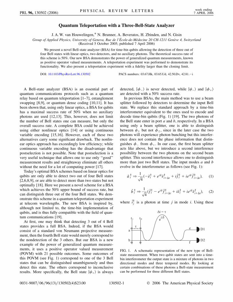
PRL 96, 130502 (2006) P H Y S I C A L R E V I E W L E T T E R S week ending7 APRIL 2006
Quantum Teleportation with a Three-Bell-State Analyzer
J. A. W. van Houwelingen,* N. Brunner, A. Beveratos, H. Zbinden, and N. GisinGroup of Applied Physics, University of Geneva, Rue de l’Ecole-de-Medecine 20 CH-1211 Geneve 4, Switzerland
(Received 5 October 2005; published 7 April 2006)
0031-9007=
We present a novel Bell-state analyzer (BSA) for time-bin qubits allowing the detection of three out offour Bell states with linear optics, two detectors, and no auxiliary photons. The theoretical success rate ofthis scheme is 50%. Our new BSA demonstrates the power of generalized quantum measurements, knownas positive operator valued measurements. A teleportation experiment was performed to demonstrate itsfunctionality. We also present a teleportation experiment with a fidelity larger than the cloning limit.
DOI: 10.1103/PhysRevLett.96.130502 PACS numbers: 03.67.Hk, 03.65.Ud, 42.50.Dv, 42.81.�i
D1
D2b
e
f
a
t1 t0
FIG. 1. A schematic representation of the new type of Bell-state measurement. When two qubit states are sent into a time-bin interferometer the output state is a mixture of photons in twodirectional modes and three temporal modes. By looking atcertain combinations of these photons a Bell-state measurementcan be performed for three different Bell states.
A Bell-state analyzer (BSA) is an essential part ofquantum communications protocols such as a quantumrelay based on quantum teleportation [1–7], entanglementswapping [8,9], or quantum dense coding [10,11]. It hasbeen shown that, using only linear optics, a BSA for qubitshas a maximal success rate of 50% when no auxiliaryphotons are used [12,13]. This, however, does not limitthe number of Bell states one can measure, but only theoverall success rate. A complete BSA could be achievedusing either nonlinear optics [14] or using continuousvariable encoding [15,16]. However, each of these twoalternatives carry some significant drawback. The nonlin-ear optics approach has exceedingly low efficiency; whilecontinuous variable encoding has the disadvantage thatpostselection is not possible. Note that postselection is avery useful technique that allows one to use only ‘‘good’’measurement results and straightaway eliminate all otherswithout the need for a lot of computing power [17].
Today’s optimal BSA schemes based on linear optics forqubits are only able to detect two out of four Bell states[2,6,8,9], or are able to detect more than two states but notoptimally [18]. Here we present a novel scheme for a BSAwhich achieves the 50% upper bound of success rate, butcan distinguish three out of the four Bell states. We dem-onstrate this scheme in a quantum teleportation experimentat telecom wavelengths. The new BSA is inspired by,although not limited to, the time-bin implementation ofqubits, and is thus fully compatible with the field of quan-tum communications [19].
At first, one may think that detecting 3 out of 4 Bellstates provides a full BSA. Indeed, if the BSA wouldconsist of a standard von Neumann projective measure-ment, then the fourth Bell state would merely correspond tothe nondetection of the 3 others. But our BSA is a newexample of the power of generalized quantum measure-ments, it uses a positive operator valued measurement(POVM) with 21 possible outcomes. Some outcomes ofthis POVM (see Fig. 1) correspond to one of the 3 Bellstates that can be distinguished unambiguously and thusdetect this state. The others correspond to inconclusiveresults. More specifically, the Bell state j �i is always
06=96(13)=130502(4)$23.00 13050
detected, j��i is never detected, while j �i and j��iare detected with a 50% success rate.
In previous BSAs, the main method was to use a beamsplitter followed by detectors to determine the input Bellstate. We replace this standard approach by a time-bininterferometer equivalent to the ones used to encode anddecode time-bin qubits (Fig. 1) [19]. The two photons ofthe Bell state enter in port a and b, respectively. In a BSAusing only a beam splitter, one is able to distinguishbetween � but not ��, since in the later case the twophotons will experience photon bunching but this interfer-ence does not contain the phase information that distin-guishes �� from ��. In our case, the first beam splitteracts like above, but we introduce a second interferencepossibility between the two photons on the second beamsplitter. This second interference allows one to distinguishmore than just two Bell states. The input modes a and bevolve in the interferometer as follows (see Fig. 1):
a yt )1���
4p ��eyt � ei�e
yt��t � if
yt � iei�f
yt��t�; (1)
b yt )1���
4p �fyt � ei�f
yt��t � ie
yt � iei�e
yt��t�; (2)
where iyj is a photon at time j in mode i. Using these
2-1 © 2006 The American Physical Society

LBOWDM
Si filterD1
WDM
Sifi
lter
β
femtosecond laser
Repetition rate =76 MHzPulse width =150 fs
Mode locked Ti:Sapphire
λp=710 nm
LBO
D2
D3
IF 5nm
IF 5nm1550 nm
1310 nm
1550 nm
1310 nm
δαAliceCharlie
Bob
FIG. 2 (color online). A rough overview of the experimentalsetup. The fiber interferometers shown here are in realityMichelson interferometers; for the interferometer in the BSAtwo circulators are used to have two separate inputs and outputs.Not shown in the figure is the method used for stabilizing theinterferometers.
TABLE I. The table shows the probability to find any of the 21 possible coincidences as a function of the input Bell-State. A 0 in rowD1 means that a photon was found at detector ‘‘D1’’ and at a time corresponding to the photon having taken the short path in theinterferometer and it was originally a photon in time-bin t0, a 1 corresponds to t0 � 1� � with � corresponding to a the differencebetween the time-bins, etc., Note that several combinations of detection are possible for only one Bell-state(the bold entries), thereforwhen such a combination is found a Bell-state measurement was performed. The theoretical probability of a successful measurement is0.5 which is the optimal value using only linear optics [12].
D1 00 11 22 01 02 12 0 2 1 1 0 1 2 0 2D2 00 11 22 01 02 12 0 2 1 0 1 2 1 2 0
j��i 1=16 1=16 1=16 1=16 1=8 1=8 1=2j��i 1=16 1=16 1=4 1=4 1=16 1=16 1=8 1=8j �i 1=8 1=8 1=8 1=8 1=8 1=8 1=8 1=8j �i 1=4 1=4 1=8 1=8 1=8 1=8
PRL 96, 130502 (2006) P H Y S I C A L R E V I E W L E T T E R S week ending7 APRIL 2006
formulas it is possible to calculate all possible outputs ofthe interferometer as a function of any input state.
These output coincidences in ports e and f, i.e., ondetectors D1 and D2, are summarized in Table I. Byconvention, a photon detected at time ‘‘0’’ means that thephoton did not accumulate any delay with regards to a fixedreference. This is only possible if the photon took the shortpath in the BSA and it was originally a photon in time-bint0 (Fig. 1). A photon detected at time ‘‘1’’ signifies that thephoton was originally in t1 and took the short path of theBSA interferometer or it was in t0 and took the long path. Adetection at time ‘‘2’’ then means the photon was in t1 andtook the long path.
In Table I one can distinguish two cases. Either the resultunambiguously distinguishes one Bell state. Or the resultcould have been caused by two specific Bell states, i.e., theresult is ambiguous and hence inconclusive.
The above described approach is correct in the case werethe phase � of the BSA interferometer is set to 0. Let usthus briefly analyze in this paragraph the situation of anarbitrary phase �. In such a case, our BSA still distin-guishes 3 Bell states, but these are no longer the Bell statesof the computational basis. For a teleportation experimentthis means the basis for the measured Bell states is not thesame as the basis for the entangled states shared betweenBob and Charlie. Still, perfect teleportation is possible, butwith the difference that the unitary transformations thatBob has to apply after receiving the classical informationabout the result of the BSA have changed and no longerinclude the identity: all unitary transformations are non-trivial, but they remain experimentally feasible. More spe-cifically, the analyzed Bell states are:
�0� � j00i � e2i�j11i; (3)
0� � ei��j01i � j10i�: (4)
These Bell states are equivalent to the standard statesexcept that the j1i is replaced by ei�j1i for each of theinput modes. Therefore the unitary transformations thathave to be applied to retrieve the original state of theteleported photon also have to be modified from
13050
[I; �z; �x; �z�x] to [�2�; �z�2�; �x; �z�x]. Here �2� �
e�2i�Pj1i � Pj0i is a phase shift of 2� to be applied to thetime-bin j1i.
In a realistic experimental environment the successprobabilities of the BSA will be affected by detector limi-tations, because existing photon detectors are not fastenough to distinguish photons which follow each otherclosely (in our case two photons separated by � �1:2 ns) in a single measurement cycle. Hence a coinci-dence, for example, ‘‘02’’ on D2, cannot be detected withour detectors. This limitation rises from the dead time ofthe photodetectors. When including this limitation we findthat the maximal attainable probabilities of success in ourexperimental setup are reduced to 1=2, 1=4, and 1=2 for �, �, and ��, respectively. This leads to an overallprobability of success of 5=16, which is greater by 25%than the success rate of 1=4 with a BSA consisting only ofone beam splitter and two identical detectors.
In order to demonstrate successful Bell-state analysis weperformed a teleportation experiment. A schematic of theexperimental setup is shown in Fig. 2. Alice prepares aphoton in the state j�Ai � j0i � ei�j1i. Bob analyzes theteleported photon and measures interference fringes foreach successful BSA announced by Charlie. The setupconsist of a mode-locked Ti:sapphire laser creating150 fs pulses with a spectral width of 4 nm, a central
2-2

PRL 96, 130502 (2006) P H Y S I C A L R E V I E W L E T T E R S week ending7 APRIL 2006
wavelength of 711 nm and a mean power of 400 mW. Thisbeam is split in two beams using a variable coupler (�=2and a PBS). The reflected light (Alice) is sent to a Lithiumtri-Borate crystal (LBO, Crystal Laser) were by parametricdown-conversion a pair of photons is created at 1.31 and1:55 �m. Pump light is suppressed with a Si filter, and thecreated photons are collected by a single mode optical fiberand separated with a wavelength-division multiplexer(WDM). The 1:55 �m photon is ignored whereas the1:31 �m is send to a fiber interferometer which encodesthe qubit on the equator of the Bloch sphere. In the sameway, the transmitted beam (Bob) is send onto another LBOcrystal after having passed through an unbalancedMichelson bulk optics interferometer, the phase of thisinterferometer is considered as the reference phase. Thenondegenerate entangled photons produced in this waycorresponds to the �� state. The photons at 1:31 �m aresend to Charlie in order to perform the Bell-state measure-ment. In order to assure temporal indistinguishability,Charlie filters the received photons down to a spectralwidth of 5 nm. In this way the coherence time of thegenerated photons is greater than that of the photons inthe pump beam, and as such we can consider the photons tobe emitted at the same time. Bob filters his 1:55 �mphoton to 15 nm in order to avoid multiphoton events[20]. A liquid-nitrogen-cooled Ge avalanche photon detec-tor (APD) D1 with passive quenching detects one of thetwo photons in the BSA and triggers the commercialinfrared APDs (id Quantique) D2 and D3. Events areanalyzed with a time to digital converter (TDC, Acam)and coincidences are recorded on a computer.
Each interferometer is stabilized in temperature and anactive feedback system adjusts the phase every 100 secondsusing separate reference lasers. In this way the quantumteleportation scheme works with independent units and isready for ‘‘in the field’’ experiments. A more detaileddescription of the active stabilization is given in Ref. [9].
The temporal indistinguishability of the photons arrivingat the BSA is usually tested by measuring a Hong-Ou-
FIG. 3 (color online). Left: The result of the 1-Bell-state tele-portation experiment (a beam splitter instead of the interferome-ter) with Fraw � 79% and Fnet � 91%. Right: A typical result ofthe scan in delay of the coincidences ‘‘00’’ and ‘‘22’’. Thepredicted antidip is clearly visible in both curves with a visibilityafter noise substraction of 32% for ‘‘0’’ on D1 and D2 and 26%for ‘‘2’’ on D1 and D2 (theoretical maximum � 1=3 [22]).
13050
Mandel dip. In our BSA this is not directly possible.Photons that have bunched on the first interferometer willbe split up by the second interferometer in a nondetermin-istic manner and as such there will be no decrease in thenumber of coincidences when looking at the same time ofarrival. There will actually be an increase for these coin-cidences because the amount of photons that took a differ-ent path in the interferometer will decrease. In ourexperimental setup this means one has to look at an in-crease in the rate of detecting a ‘‘0’’ on both D1 and D2 andthe same is true for the rate of ‘‘2’’ on D1 and D2. A typicalresult from this alignment procedure can be found in Fig. 3.
First we performed a quantum teleportation with inde-pendent units using a beam splitter for the Bell-state mea-surement. This enables us to test our setup in terms offidelity. In order to check the fidelity of the teleported sate,Bob sends the teleported photon through an analyzinginterferometer and measures the interference fringes con-ditioned on a successful BSA. When Bob scans the phaseof his interferometer we obtained a raw visibility of V �57% (F � 79%) and a net visibility of V � 83%� 4 (F �91%� 2) clearly higher than the cloning limit of F � 5=6(Fig. 3). We then switched to the new BSA. This new setupintroduces about 3 dB of excess loss, due to added opticalelements including the interferometer and its stabilizationoptics. These losses result in a lower count rate. Forexperimental reasons we now scan the interferometer ofAlice instead of Bob. The experiments were performed forapproximately 4.4 hours per point in order to accumulateenough data to have low statistical noise. The expectedinterference fringes after Bob’s interferometer are of theform 1� cos��� � for a projection on � and 1�cos��� � 2�� for a projection on��. Hence one would
FIG. 4 (color online). These graphs show the interferencefringes found when scanning the interferometer at Bob. we foundvisibilities of 0.22,0.43 and 0.38 for j �i, j��i and j �i. Theaverage visibility of the BSA is Vavg � 0:34 (F � 0:67).
2-3

FIG. 5 (color online). This graph shows two measurementsthat were taken with a different value of �. The closed datapointscorrespond to a measurement with � equal to �. The openpoints are for a � which was shifted by 35� 5�. There is a clearshift of the fringe for j��i by 74� with regards to the otherfringes which corresponds to the expected value of 70� 10�.
PRL 96, 130502 (2006) P H Y S I C A L R E V I E W L E T T E R S week ending7 APRIL 2006
expect to find three distinct curves, two with a phasedifference of , and the third dephased by �2�� ��,where �, , and � are the phases of Alice, Bob, and theBSA interferometer, respectively. Note that Bob is able toderive � using the phase difference between the fringesmade by � and �� since this difference corresponds to2��� �, where is Bob‘s local phase.
In Fig. 4 we show the coincidence interference fringesbetween Bob and a successful BSA. As expected fringesfor j �i and j �i have a phase difference due to thephase flip caused by the teleportation. On the other hand,fringes for j �i and j��i are dephased by �2�� ��,which in this case we had arranged to be approximately 0.The count rates for the different Bell states differ becausethey correspond to different numbers of detection combi-nations. The raw (Fig. 4) visibilities obtained for the pro-jection on each Bell state are V � � 0:38, V � � 0:22,V�� � 0:43, which leads to an overall value of V � 0:34(F � 0:67). If we subtract the noise we find net visibilitiesof 0.51,0.69, and 0.55 for j �i, j��i and j �i which leadsto an average of V � 0:58 (F � 0:79). Note that the maxi-mal value that can be attained without the use of entangle-ment is Vmax � 1=3 [21]. Two of the raw visibilities and allof the net visibilities break this limit. In order to check thedependence of j��i on �we also performed a teleportationwith a different value and we clearly observe the expectedshift in the fringe (Fig. 5) while measuring similarvisibilities.
Finally the authors would like to stress two points aboutthis novel BSA. First it is possible to implement this BSAfor polarization encoded photons by creating a second
13050
interference possibility for H and V polarization. Thiswould require 4 detectors, but an overall efficiency of50% can be achieved with current day detectors. The limitof 50% can also be achieved with time-bin encoded qubitsbut would require the use of ultra fast optical switches andtwo more detectors. We did not implement this due to thelosses associated with introducing current day high speedintegrated modulators. Second, even though three out offour Bell states can be distinguished, one cannot use thisscheme in order to increase the limit of log23 bits persymbol for quantum dense coding.
In conclusion, we have shown experimentally that it ispossible to perform a three-state Bell analysis while usingonly linear optics and without any actively controlled localoperations on a single qubit. In principle this measurementcan obtain a success rate of 50%. We have used this BSA toperform a teleportation experiment, and obtained a non-corrected overall fidelity of 67%, after noise substractionwe find F � 76%. Also, we performed a teleportationexperiment with a one state BSA which exceeded thecloning limit.
The authors acknowledge financial support from theEuropean IST-FET Project ‘‘RamboQ’’ and from theSwiss NCCR Project ‘‘Quantum Photonics’’ and thankC. Barreiro and J.-D. Gautier for technical support.
2-4
*Electronic address: [email protected]
[1] C. H. Bennett et al., Phys. Rev. Lett. 70, 1895 (1993).[2] D. Bouwmeester et al., Nature (London) 390, 575 (1997).[3] D. Boschi et al., Phys. Rev. Lett. 80, 1121 (1998).[4] E. Waks et al., Phys. Rev. A 65, 052310 (2002).[5] B. C. Jacobs et al., Phys. Rev. A 66, 052307 (2002).[6] I. Marcikic et al., Nature (London) 421, 509 (2003).[7] D. Collins et al., J. Mod. Opt. 52, 735 (2005).[8] J.-W. Pan et al., Phys. Rev. Lett. 80, 3891 (1998).[9] H. de Riedmatten et al., Phys. Rev. A 71, 050302(R)
(2005).[10] C. H. Bennett and S. J. Wiesner, Phys. Rev. Lett. 69, 2881
(1992).[11] K. Mattle et al., Phys. Rev. Lett. 76, 4656 (1996).[12] J. Calsamiglia et al., Appl. Phys. B 72, 67 (2001).[13] E. Knill et al., Nature (London) 409, 46 (2001).[14] Y.-H Kim et al., Phys. Rev. Lett. 86, 1370 (2001).[15] S. L. Braunstein et al., Phys. Rev. Lett. 80, 869 (1998).[16] A. Furusawa et al., Science 282, 706 (1998).[17] For experiments on the nature of physics, such as Bell
tests, postselection can be a drawback. For applications inquantum communication, however, it is advantageoussince it selects useful measurement results.
[18] P. Walther et al., Phys. Rev. A 72, 010302(R) (2005).[19] W. Tittel et al., Quantum Inf. Comput. 1, 3 (2001).[20] V. Scarani et al., Eur. Phys. J. D 32, 129 (2005).[21] S. Massar et al., Phys. Rev. Lett. 74, 1259 (1995).[22] H. de Riedmatten et al., Phys. Rev. A 67, 022301 (2003).

Experimental quantum teleportation with a three-Bell-state analyzer
J. A. W. van Houwelingen,* A. Beveratos, N. Brunner, N. Gisin, and H. ZbindenGroup of Applied Physics, University of Geneva, CH-1211 Geneve 4, Switzerland
�Received 28 April 2006; published 3 August 2006�
We present a Bell-state analyzer for time-bin qubits allowing the detection of three out of four Bell stateswith linear optics, two detectors, and no auxiliary photons. The theoretical success rate of this scheme is 50%.A teleportation experiment was performed to demonstrate its functionality. We also present a teleportationexperiment with a fidelity larger than the cloning limit of F= 5
6 .
DOI: 10.1103/PhysRevA.74.022303 PACS number�s�: 03.67.Hk, 42.50.Dv, 42.81.�i
I. INTRODUCTION
Bell-state analyzers �BSA� form an essential part of quan-tum communications protocols. Their uses range from quan-tum relays based on teleportation �1–7� or entanglementswapping �8,9� to quantum dense coding �10,11�. An impor-tant restriction for BSAs is that a system based on linearoptics, without using auxiliary photons, is limited to a 50%overall success rate �12,13�. This important result does notrestrict the number of Bell states that can be measured, butonly the overall efficiency of a measurement. Nevertheless, acomplete BSA is possible for at least two different cases: thefirst approach uses nonlinear optics �14� but this has thedrawback of an exceedingly low efficiency and is, therefore,not well adapted for quantum communication protocols. An-other possibility is the use of continuous variable encoding�15,16�, however, this technique has the disadvantage thatpostselection is not possible. Note that postselection is a veryuseful technique that allows one to use only “good” measure-ment results and straightaway eliminate all others withoutthe need for great computational analysis.
Many experiments have been done up to date that useBSAs. In this paper a different BSA is introduced �17�. It hasthe maximum possible efficiency that can be obtained whenusing only linear optics without ancilla photons. It is differ-ent with respect to other BSAs since it can distinguish threeout of the four Bell states. All of the used BSAs up to datethat can reach the maximum efficiency, without the use ofancilla photons, are limited to two �or less� Bell states�2,6,8,9,18�. There have also been experiments of a BSA thatdetects all four Bell states but its overall efficiency does notreach 50% and it requires the use of an entangled ancillaphoton pair �19�.
II. THEORY
A. Time-bin encoding
In our experiments a qubit is encoded on photons usingtime bins �20�. This means that a photon is created that existsin a superposition of two well-defined instants in time �timebins� that have a fixed temporal separation of �. By conven-tion the Fock state with N=1 corresponding to a photon inthe early time of existence t0 is written as �0� and for the later
time t1= to+� as �1�. Photons in such a state can be created inseveral ways. The simplest method is to pass a single photonthrough an unbalanced interferometer with a path length dif-ference of nc�, where n is the refractive index. After theinterferometer the photon will be in the qubit state A�0�+ei�B�1�. Here A and B are amplitudes that depend on thecharacteristics of the interferometer and � is the phase dif-ference between the interferometer paths which is directlydetermined by �= �2�nc� /���mod 2��. For the sake of read-ability we will use the word qubit when talking about a“photon that is in a qubit state.”
B. Bell-state analyzer
In a large part of all experiments using BSAs that havebeen performed up to date, the BSA consists essentially of abeamsplitter and single-photon detectors �SPDs�. In such abeamsplitter-BSA�BS-BSA� the “clicks” of the SPDs areanalyzed and, depending on their results, the input state willbe projected onto a particular Bell state. With time-bin qubitsas described above a simple BS-BSA works as follows: twoqubits arrive at the same time on a beamsplitter but at differ-ent entry ports. Since the four standard Bell states
��±� =1�2
��00� ± �11�� , �1�
��±� =1�2
��01� ± �10�� �2�
form a complete basis we can write our two-qubit input stateas a superposition of these four states. One can calculate foreach Bell input state the possible output states. These statescan then be detected using SPDs. The different detectionpatterns and their probabilities are shown in Table I. By con-vention, a detection click at time “0” �“1”� means that thephoton was detected in the time bin t0 �t1�. The output com-binations show that, if one detects two photons in the samepath but in a different time bin, the input state could onlyhave been caused by the Bell state ��+� and therefore theoverall state of the system is projected onto this state. Whenthe photons arrive at different detectors with a time-bin dif-ference the input state is projected onto the state ��−�. How-ever, when one measures two photons in the same time bin inthe same detector the state could either be ��+� or ��−�, andtherefore the state has not been projected onto a single Bell*Email address: [email protected]
PHYSICAL REVIEW A 74, 022303 �2006�
1050-2947/2006/74�2�/022303�12� ©2006 The American Physical Society022303-1
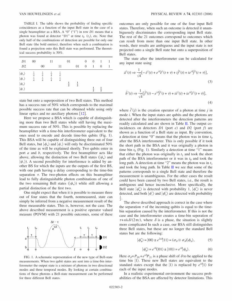
state but onto a superposition of two Bell states. This methodhas a success rate of 50% which corresponds to the maximalpossible success rate that can be obtained while using onlylinear optics and no auxiliary photons �12�.
Here we propose a BSA which is capable of distinguish-ing more than two Bell states while still having the maxi-mum success rate of 50%. This is possible by replacing thebeamsplitter with a time-bin interferometer equivalent to theones used to encode and decode time-bin qubits �Fig. 1�.This BSA will be capable of distinguishing three out of fourBell states, but ��+� and ��−� will only be discriminated 50%of the time as will be explained shortly. Two qubits enter inport a and b, respectively. The first beamsplitter acts likeabove, allowing the distinction of two Bell states ���+� and��−��. A second possibility for interference is added by an-other BS for which the inputs are the outputs of the first BS,with one path having a delay corresponding to the time-binseparation �. The two-photon effects on this beamsplitterlead to fully distinguishable photon combinations of one ofthe two remaining Bell states ���+�� while still allowing apartial distinction of the first two.
One might expect that when it is possible to measure threeout of four states that the fourth, nonmeasured, state cansimply be inferred from a negative measurement result of thethree measurable states. This is, however, not the case. Theabove described measurement is a positive operator valuedmeasure �POVM� with 21 possible outcomes, some of these
outcomes are only possible for one of the four input Bellstates. Therefore, when such an outcome is detected it unam-biguously discriminates the corresponding input Bell state.The rest of the 21 outcomes correspond to outcomes whichcan result from more than one input Bell state. In otherwords, their results are ambiguous and the input state is notprojected onto a single Bell state but onto a superposition ofBell states.
The state after the interferometer can be calculated forany input state using
a†�t� Þ1�4
�− e†�t� + ei�e†�t + �� + i f†�t� + iei� f†�t + ��� ,
�3�
b†�t� Þ1�4
� f†�t� − ei� f†�t + �� + ie†�t� + iei�e†�t + ��� ,
�4�
where i†�j� is the creation operator of a photon at time j inmode i. When the input states are qubits and the photons aredetected after the interferometers the detection patterns arereadily calculated and are shown in Table II. The output co-incidences on detectors D1 �port e� and D2 �port f� areshown as a function of a Bell state as input. By convention,a detection at time “0” means that the photon was in time t0after the BSA interferometer. This is only possible if it tookthe short path in the BSA and it was originally a photon intime bin t0 �Fig. 1�. Similarly a detection at time “1” meansthat either the photon was originally in t1 and took the shortpath of the BSA interferometer or it was in t0 and took thelong path. A detection at time “2” means the photon was in t1and took the long path. In Table II we see that some of thepatterns corresponds to a single Bell state and therefore themeasurement is unambiguous. For the other cases the resultcould have been caused by two Bell states, i.e., the result isambiguous and hence inconclusive. More specifically, theBell state ��+�� is detected with probability 1, ��−�� is neverdetected, and both ��−�� and ��+�� are detected with probability12 .
The above described approach is correct in the case wherethe separation � of the incoming qubits is equal to the time-bin separation caused by the interferometer. If this is not thecase and the interferometer creates a time-bin seperation of�+n�� / �2�c�, where � is a phase, the situation is slightlymore complicated In such a case, our BSA still distinguishesthree Bell states, but these are no longer the standard Bellstates but are the following:
��±�� = �00� ± e2i��11� = �� � ����±� , �5�
��±�� = ei���01� ± �10�� = ei���±� . �6�
Here �= P�0�+ei�P�1� is a phase shift of � to be applied to thetime bin �1�. These new Bell states are equivalent to thestandard states except that the �1� is replaced by ei��1� foreach of the input modes.
In a realistic experimental environment the success prob-abilities of the BSA are affected by detector limitations. This
TABLE I. The table shows the probability of finding specificcoincidences as a function of the input Bell state in the case of asingle beamsplitter as a BSA. A “0” �“1”� in row D1 means that aphoton was found at detector “D1” at time t0 �t1�, etc. Note thatonly half of the combinations of detection are possible for only oneBell state �the bold entries�, therefore when such a combination isfound a projection onto this Bell state was performed. The theoret-ical success probability is 50%.
D1 00 11 01 0 0 1 1
D2 00 11 01 0 1 0 1
��+� 14
14
14
14
��−� 14
14
14
14
��+� 12
12
��−� 12
12
FIG. 1. A schematic representation of the new type of Bell-statemeasurements. When two qubit states are sent into a time-bin inter-ferometer the output state is a mixture of photons in two directionalmodes and three temporal modes. By looking at certain combina-tions of these photons a Bell-state measurement can be performedfor three different Bell states.
VAN HOUWELINGEN et al. PHYSICAL REVIEW A 74, 022303 �2006�
022303-2

is because existing photon detectors are not fast enough todistinguish photons which follow each other closely �in ourcase two photons separated by �=1.2 ns� in a single mea-surement cycle. This limitation rises from the dead time ofthe photodetectors. When including this limitation we findthat the maximal probabilities of success in our experimentalsetup are reduced to 1
2 , 14 , and 1
2 for �+, �−, and �+, respec-tively. This leads to an overall probability of success of 5
16which is greater by 25% than the success rate of 1
4 for a BSAconsisting only of one beamsplitter and two detectorswith the same limitation. This limitation could be partiallyeliminated by using a beamsplitter and two detectors inorder to detect the state 50% of the time, or it could becompletely eliminated by using an ultrafast optical switch�sending each time bin to a different detector�. Both of thesemethods are associated with a decrease in the signal-to-noiseratio. This is caused by the additional noise from the addeddetector and by additional losses from the optical switch,respectively.
C. Bell-state analyzer for polarization qubits
So far the discussion about this BSA only consideredtime-bin qubits. The authors would like to note at this pointthat it is also possible to implement a similar BSA for polar-ization encoded photons. This can be done by the equivalentpolarization setup as shown in Fig. 2. This setup would re-quire four detectors but there will never be two photons onone detector and therefore dead times do not hinder the mea-surement of all the detection patterns and the overallefficiency can reach 50% with today’s technology.
D. Four-Bell-state analyzer?
This paper discusses our results testing a three-Bell-stateanalyzer. It is obviously interesting to also consider the pos-sibility of a linear optics four-Bell-state analyzer with 50%efficiency and no ancilla photons. Such a system was notused for the simple reason that there is no known method tomake such a measurement. Is there a fundamental reason tosuspect that such a BSA cannot be performed? No such rea-son is known to the authors, therefore this paper will belimited to the three-Bell-state analyzer.
E. Teleportation
One of the most stunning applications of a BSA is its usein the teleportation protocol. In order to perform a teleporta-tion experiment an entangled qubit photon pair is created�EPR �21�� as well as a qubit to be teleported �Alice�. Onephoton of the entangled pair is made to interact with Alice’squbit in a BSA �Charlie�. This interaction followed by detec-tion projects the overall state onto a Bell state �if the BSA issuccessful�. The remaining photon �Bob� now carries thesame information as the photon from Alice up to a unitarytransformation. The situation for the new BSA is slightlydifferent since the entangled pair is not a member of thedetected Bell basis �Eqs. �5� and �6��. However this has nomajor influence on the theory. After a succesful measurementof the BSA the remaining photon at Bob is equal to theoriginal qubit up to a unitary transformation. This transfor-mation, however, has to be adapted with regards to the stan-dard case from �1 ,z ,x ,xz� to �2�
−1 ,z2�−1 ,x ,xz�, as
can be seen from the following calculation:
TABLE II. The table shows the probability of finding any of the 21 possible coincidences as a function of the input Bell state. A “0” inrow D1 means that a photon was found at detector “D1” and at a time corresponding to the photon having taken the short path in theinterferometer and it was originally a photon in time-bin t0, a “1” corresponds to t0+1� with � corresponding to the difference betweenthe time bins, etc. Note that several combinations of detection are possible for only one Bell state �the bold entries�, therefore when such acombination is found a Bell-state measurement was performed. The theoretical probability of a successful measurement is 0.5 which is theoptimal value using only linear optics �12�.
D1 00 11 22 01 02 12 0 2 1 1 0 1 2 0 2
D2 00 11 22 01 02 12 0 2 1 0 1 2 1 2 0
��+�� 116
116
116
116
18
18
12
��−�� 116
116
14
14
116
116
18
18
��+�� 18
18
18
18
18
18
18
18
��−�� 14
14
18
18
18
18
FIG. 2. A schematic representation of the new type of a Bell-state analyzer for polarization qubits. The gray cubes represent non-polarizing beamsplitters and the white cubes are polarizingbeamsplitters.
EXPERIMENTAL QUANTUM TELEPORTATION WITH A¼ PHYSICAL REVIEW A 74, 022303 �2006�
022303-3

��abc� = ���a � ��+� �7�
= 12 ���+��ab � 2�
−1���c�
+ ��−��ab � z2�−1���c
+ ��+��ab � e−i�x���c
+ ��−��ab � e−i�xz���c. �8�
Recall 2�−1= P�0�+e−2i�P�1� is a phase shift of the bit �1�.
III. EXPERIMENTAL TELEPORTATION
The BSA was tested in a quantum teleportation experi-ment. Presented in this section is the experimental setup thatwas used as well as some of the required preliminary align-ment experiments. Finally, the results of the experiment aregiven and discussed.
A. Experimental setup
A rough schematic of the experimental setup is shown inFig. 3; the experiment is an adaptation of a setup used pre-viously for long distance teleportation �6� and for entangle-ment swapping �9�. Alice prepares a photon in the state���a= �1/�2���0�+ei��1��. A BSA is used by Charlie on Al-ice’s qubit combined with a part of an entangled qubit pair.Bob analyzes the other half of the pair �the teleported qubit�and measures interference fringes for each successful BSAannounced by Charlie.
The setup consists of a mode-locked Ti-sapphire laser�MIRA with 8W VERDI pump-laser, Coherent� creating150 fs pulses with a spectral width of 4 nm, a central wave-length of 711 nm, a mean power of 400 mW and a repetitionrate of 80 MHz. This beam is split in two beams using avariable coupler �� /2 and a PBS�. The reflected light �Alice�is sent to a scannable delay and afterwards to a lithium tri-borate crystal �LBO, crystal laser� where by parametric
downconversion a pair of photons is created at 1.31 and1.55 �m. Pump light is suppressed with a Si filter, and thecreated photons are collected by a single mode optical fiberand separated with a wavelength-division multiplexer�WDM�. The 1.55 �m photon is ignored, whereas the photonat 1.31 �m is send to a fiber interferometer which encodesthe qubit state ���a onto the photon. The transmitted beam�Bob� is passed through an unbalanced Michelson-type bulkinterferometer. The seperation between the two time bins af-ter this interferometer is considered as the reference for allthe other seperations. The phase of the interferometer can,therefore, be considered as a reference phase and can bedefined as 0. After the interferometer the beam passes a dif-ferent LBO crystal. The nondegenerate photon pairs createdin this crystal are entangled and their state corresponds to��+�= �1/�2���00�+ �11��.
The photons at 1.31 �m are send to Charlie in order toperform the Bell-state measurement. To assure temporal in-distinguishability, Charlie filters the received photons downto a spectral width of 5 nm using a bulk interference filter.Because of this the coherence time of the generated photonsis greater than that of the photons in the pump beam, and assuch no distinguishablity between photons can be caused byjitter in their creation time �22�. Bob filters his 1.55 �m pho-ton to 15 nm in order to avoid multi photon-pair events�23,24�, this filtering is done by the WDM that separates thephotons at 1.31 and 1.5 �m. This filter is larger than Char-lie’s filter for experimental reasons. A liquid nitrogen cooledGe avalanche-photon detector �APD� D1 with passivequenching detects one of the two photons in the BSA andtriggers the InGaAs APDs �id Quantique� D2 and D3. Eventsare analyzed with a time to digital converter �TDC, Acam�and coincidences are recorded on a computer.
Each interferometer is stabilized in temperature and forgreater stability an active feedback system adjusts the phaseevery 100 s using reference lasers. The reference for Bob’sinterferometer is a laser �Dicos� stabilized on an atomictransition at 1531 nm and for both Alice’s and Charlie’s
FIG. 3. �Color online� A rough overview of the experimental setup. The fiber interferometers shown here are in reality Michelsoninterferometers, for the interferometer in the BSA two circulators are used to have two separate inputs and outputs. Not shown in the figureis the method used for stabilizing the interferometers.
VAN HOUWELINGEN et al. PHYSICAL REVIEW A 74, 022303 �2006�
022303-4

interferometer a stabilized distributed-feedback �DFB� laser�Dicos� at 1552 nm is used. It is possible to use differentlasers for Alice and Charlie if one wants to create two inde-pendent units. By using independent interferometer units us-ing different stabilization lasers it was assured that this ex-periment is ready for use “in the field.” A more detaileddescription of the active stabilization of the interferometersis given in Ref. �9�. For sake of clarity the interferometersshown in the setup �Fig. 3� are Mach-Zender-type interfer-ometers but in reality they are Michelson interferometerswhich use Faraday mirrors in order to avoid distinguishabil-ity due to polarization differences �25�.
B. Alignment experiments
There are two important, nontrivial alignments that haveto be made before one can perform a quantum teleportationexperiment with time-bin encoded qubits. First, one wouldhave to assure that all the time-bin interferometers have thesame difference in length between the two paths. Second, itis required that there is temporal indistinguishability betweenqubits coming from Alice and Bob on the BSA. The equal-ization of the interferometers is needed in order to assure thatall the interferometers have a difference in length of c� /nwith a precision higher than the coherence length of the pho-tons ��150 �m�. We have two mechanisms to activelychange the optical path lengths: the first is changing the tem-perature of the interferometers and thus allowing the longarm to increase or decrease its length more than the shortarm and the second is to directly change the length of onlyone arm by means of a cylindric piezoelectric element. Whenchanging the voltage over the piezo we change the diameterof the cylinder and thus the length of the fiber changes. Thisis used for the active feedback stabilization system. In orderto align the interferometers with each other we perform twodifferent experiments: First, we optimize the visibilty ofsingle-photon interference fringes for photons from Alice de-tected in D1. This aligns Alice’s interferometer with the BSAinterferometer. Next, we optimize a Fransson-type Bell testof the entangled photon pair �26�. While optimizing this ex-periment we do not change the BSA interferometer. Thisoptimization aligns the bulk interferometer and Bob’s analy-sis interferometer to the other two. Using this method wefound visibilities of 97% ±1% for the single photon interfer-ence and 94% ±1% for the Bell test �Fig. 4�.
The second alignment procedure is necessary in order toassure temporal indistinguishability between the photons ar-riving at the BSA. In the case of a BS-BSA this can beassured by performing a Hong-Ou-Mandel dip type experi-ment �27�, which is to say, make a scan in a delay for one ofthe incoming photons and look at a decrease in the numberof coincidences as a result of photon bunching �Fig. 5�. Theposition where the minimum is obtained corresponds to thepoint with maximal temporal overlap of the two photons.
In the case of an interferometer-BSA �IF-BSA� this pro-cedure becomes more complicated. We can no longer look ata mandel dip because the second beamsplitter will probabi-listically split up the photons that bunched on the first beam-splitter. However, the photon bunching remains and it can
still be seen by a different method. Consider the situationwhere two single photons, both in the state �0�, are send tothe different inputs of an IF-BSA �Fig. 6�. If the photons arenot temporally indistinguishable there are three possible out-put differences between detection times, corresponding to“10”, “00&11”, and “01”. If the photons are indistinguish-able they bunch at the first BS and therefore the difference inarrival time between the photons has to be zero. This meansthat “10” and “01” are not possible anymore and the possi-bility for “00&11” is larger. If the inputs are arbitrary qubitsinstead of the simple example above there will be more co-incidence possibilities and some of them will be subject tosingle-photon interference and/or photon bunching. It is pos-sible to see an increase in the coincidences for “00” and“22”, which is not affected by a single-photon interference,for similar reasons as the increase that was explained above.These coincidences can be measured in a straightforwardway with our setup. A more rigorous calculation and expli-cation of this alignment procedure is given in the Appendix.A typical result of an experiment in which the count rate ismeasured while changing a delay is shown in Fig. 5 andclearly shows the expected increase in count rate.
The measured antidips have a net visibility of 32±3 %and 26±2 % after noise substraction. The maximal attainablevalue is 1
3 due to undesired but unavoidable double-pairevents �see appendix�. The large visibilities mean that thetemporal indistinguishability is very good, this will thus not
FIG. 4. �Color online� Top: Single photon interferencewith Vnet=0.97±0.01. Bottom: Fransson-type Bell test withVnet=0.94±0.01.
EXPERIMENTAL QUANTUM TELEPORTATION WITH A¼ PHYSICAL REVIEW A 74, 022303 �2006�
022303-5
be limiting for our experiments. The noise substraction forthis estimation is justified because in a teleportation experi-ment the noise will be reduced since one will consider onlythree-photon events. The difference in height of the two co-incidences is related to an electronic loss of signal in anelectrical delay line.
C. Experimental results
Two different types of teleportation experiments were per-formed. Namely a standard BS-BSA teleportation in order to
benchmark our equipment followed by the IF-BSA experi-ment. For the BS-BSA, the main difference with regards toprevious experiments �9,23� was that the interferometersnow all had an active stabilization. This allows for largestability and long measurement times. The experiment con-sisted of Bob scanning of his interferometer phase while theother interferometers where kept constant, we therefore ex-pect to find an interference curve of the form 1+V sin� +�� where � is kept constant. The results of the experiment�Fig. 7� clearly shows the expected behavior. The visibilitymeasured was V=0.57±0.03 �F=0.79±0.02�. After conser-vative noise substraction we find V=0.83±0.04 �F=0.91±0.02�. This clearly is higher than the strictest thresh-old that has been associated with quantum teleportation ofF= 5
6 �28,29�. The limiting factors of this experiment are thedetectors and the fiber coupling after the LBO crystals.
After this experiment the setup was changed to the IF-BSA. The count rates in this experiment with regards to theprevious one is reduced due to two reasons. The introductionof the BSA interferometer and its stabilization optics meansan additional 3 dB of loss which reduces count rates. An-other difference is that now the counts are distributed overthree different Bell states, whereas before there was onlyone. Therefore an overall reduction of counts per state willoccur. Combined these effects result in a large reduction ofthe count rate per Bell state. This problem was overcome by,on the one hand, an overall increase of the BSA efficiency by14 �from 25% for the BS-BSA to 31.25% for the IF-BSA�and, on the other hand, by integrating data over longer timeperiods. During the teleportation experiment scans weremade in the interferometer of Alice rather than Bob. Thiswas done since the most important noise is dependent of thephase of Bob’s interferometer but not of Alice’s �more de-tails are given in the next subsection�. The experiments wereperformed with approximately 4.4 h per phase setting in or-der to have low statistical noise.
For this IF-BSA all the different unambiguous results�Table II� were analyzed both separately �for example, “02”�and combined as a Bell state �for example, ��−�= �02�+ �20��.For the separate results it is expected that each BSA outcomewill have count rates depending on the phases of the
FIG. 5. �Color online� Top, IF-BSA: Graph showing the numberof measured coincidences as a function of a change in the delayline.Both “00” and “22” clearly show an antidip at the same location.The net visibilities are V00=32±3 % and V22=26±2 % Bottom,BS-BSA: Graph showing the decrease in the number of measuredcoincidences 00 as a function of a change in the delayline �27�. Thenet visibility is V=29±3 %.
FIG. 6. The simple experiment on the left �one photon in eachinput of an IF-BSA� will have the following property. If the photonsare not temporally indistinguishable one will find three differentcoincidence peaks: “10”,“00& 11”, and “01” �dotted curve�, how-ever, if the photons are indistinguishable there will be only onepeak: 00 and 11 �plain curve�. This is caused by photon bunching.
FIG. 7. �Color online� The result of the one-Bell state telepor-tation experiment �a beamsplitter instead of the interferometer� withFraw=0.79±0.02 and Fnet=0.91±0.02.
VAN HOUWELINGEN et al. PHYSICAL REVIEW A 74, 022303 �2006�
022303-6

interferometers as R�1+V cos��+���. Here R is dependent ofthe overall efficiency of the experiment and is different foreach BSA outcome and � is a combination of the constantphases of the interferometers of Bob and Charlie and isdifferent for different BSA results:
��+�, �01�, �10�, �12�, �21� → � = , �9�
��+�, �11� → � = − − 2� , �10�
��−�, �02�, �20� → � = + � . �11�
As is evident from the differences in � we expect that fringescorresponding to one particular Bell state are in phase witheach other, but have a well-determined phase difference withfringes corresponding to another Bell state.
The measured count rates as a function of the phase ofAlice’s interferometer are shown in �Fig. 8�. Note that, due toexperimental restrictions, the absolute phases of the interfer-ometers are not known and therefore all phase values have anunknown offset. The results clearly show that each of theoutcomes has the expected interference behavior. Further-more, the fringe corresponding to “01” is in phase with thefringe “21”. The same is true for the fringe “10” with “12”
and for “02” with “20”. It is expected that all four of thefringes corresponding to ��+� �“01”, “10”, “ 12”, and “21”�are all in phase with each other, but there is a clear phaseshift between the first two and the last two. The averagephase of these four fringes is different by 180° from thefringes corresponding to “02” and “20” as expected. Thefringe corresponding to “11” is in phase with the fringesof “02” and “20” as was expected since for this measurementwe had arranged 2� +��=��mod 2��. The results of thefits to these fringes is shown in Table III. The differencesin phase and visibility are in part due to noise �see nextsubsection�
The results corresponding to each of the three possibleBell states can be found by adding the measurements of theconstituent parts. When doing this one would expect coinci-dence fringes of the form R�1+V cos��+��� with R and � asabove. This corresponds to three distinct interference fringes,with ��+� and ��−� in phase and ��+� with a 180° phasedifference with respect to the other two.
In Fig. 9 we show the raw coincidence interferencefringes between the detection rate at Bob and a successfulBSA as a function of a change of phases in Alice’s interfer-ometer. As expected fringes for ��−� and ��+� have a180° phase difference due to the phase flip caused by the
FIG. 8. �Color online� Measured coindance counts as a function of phase. Top-left: BSA results 01, 10. Bottom-left: BSA results “12”,“21”. Top-right: BSA results “02” and “20”, Bottom-right: BSA results “11”. Note that for each graph there is an unknown, but equal, offsetof the phase value.
EXPERIMENTAL QUANTUM TELEPORTATION WITH A¼ PHYSICAL REVIEW A 74, 022303 �2006�
022303-7

teleportation. On the other hand, the fringe for ��+� is inphase with the ��+� as expected. The raw visibilities obtainedfor the projection on each Bell state are V�−
=0.38±0.05,V�+
=0.22±0.01, V�+=0.43±0.03 which leads to an overall
value of V=0.34±0.06 �F=0.67±3�. In order to check thedependence of ��+� on � we also performed a teleportationwith a different value for � and we clearly observe the ex-pected shift in the fringe �Fig. 10� while measuring similarvisibilities.
Note that Bob is able to derive the phase value � of theBSA interferometer just by looking at the phase differencesbetween the fringes made by �± and �+ and his knowledgeabout . It is important to know � since this allows Bob toperform the unitary transformation 2� on the teleported pho-
ton. Since the count rates were quite low we expected tohave an important noise factor, an analysis of the noisefollows in the next subsection.
D. Noise analysis and discussion
In the case of the BS-BSA the noise analysis is straight-forward. All of the important noise counts are completelyindependent of the phase, since they concern situations inwhich there is no single-photon interference possible. Themost important sources of noise were estimated and thenmeasured. The estimated signal-to-noise ratio was 2.6, mea-surements find a SNR of approximately 2.2±0.5. The largestsource of noise are darkcounts at one detector combined withtwo real detections.
TABLE III. For each of the different detection possibilities the fitted results are shown before and afternoise correction. V refers to the visibility �%�, � to the phase of the fringes �degrees, unknown offset� and Pto the normalized probabilities of a coincidence detection �%�. The last three rows correspond to fits madeafter adding the corresponding BSA outcomes, therefore these values can be slightly different from theaverage of the individual results.
Result 3BSA Vraw Vnet �raw �net Praw Pnet
��+�
�01� 35±3 61±6 278±4 279±5 13±1 14±1
�10� 43±3 72±13 339±4 338±8 11±1 13±1
�12� 18±3 64±7 340±7 340±4 14±1 7±1
�21� 13±2 36±2 227±9 278±1 17±1 10±1
��+� �11� 43±3 55±2 136±3 136±10 29±1 41±1
��−��02� 40±5 83±13 126±12 126±8 8±1 6±1
�20� 39±4 62±10 153±4 153±8 9±1 9±1
��+� 22±1 51±3 311±3 311±3 54±1 43±1
��+� 43±3 55±2 136±10 136±3 29±1 41±1
��−� 38±5 69±10 140±6 140±7 17±1 15±1
FIG. 9. �Color online� Uncorrected teleportation fringes foundwhen scanning the interferometer at Bob. The fitted curves havevisibilities of 0.22, 0.43, and 0.38 for ��+�, ��+�, and ��−�. Theaverage visibility of the BSA is Vavg=0.34 �F=0.67�.
FIG. 10. �Color online� Teleportation fringes measured in twodistinct measurements with a � which had changed by 70° ±10°. Inthe measurement a clear shift is visible of the fringe ��+� by 74°with regards to the other fringes.
VAN HOUWELINGEN et al. PHYSICAL REVIEW A 74, 022303 �2006�
022303-8

The situation for the IF-BSA is more complicated. Theadditional interferometer has an unfortunate side effect.There are now possibilities for noise to depend on the phasesof the interferometers. In other words, while measuring in-terference fringes there are also noise fringes. It it obviouslyimportant to be able to distinguish between the two. Themost important fluctuating noise is caused by false coinci-dence detections that involve one �or more� photons comingfrom Alice and no photons from the EPR source at the BSA.These noise sources depend on the phases � and � since the
photon coming from Alice experiences a single-photon inter-ference. Since during the experiment � is changed the noiserate also changes. The period of this change is the same asfor teleportation, however, there is a � phaseshift between“01” �“21”� and “10” �“12”� that is not present in the tele-portation signal. Such a noise influences the results of ourmeasurements in different ways, first of all, the visibilitiesare altered and are smaller for “01” and “21” but larger for“10” and “12”. Secondly, when the fringe is not in phasewith the teleportation signal there is a phaseshift in the op-posite direction for “01” and “21” with regards to “10” and“12”. In our measurements the phases were arranged in sucha way that this second effect would not take place since thefringes would be completely in or out of phase with theteleportation signal. This noise was measured and the result�Fig. 11� clearly shows the expected fringes and phaseshifts.
Other possibilities for fluctuating noise sources are whenno photons from Alice arrive at the BSA. In this case single�or multiple� photon pairs from the EPR source combinedwith darkcounts will give coincidences that depend on thephases and �. This corresponds to a combination of aFransson-type Bell test with a darkcount. The fluctuation ofthis noise was avoided in our experiment since we onlychanged the phase of Alice’s interferometer ���.
Not all possible sources of noise depend on the phases ofthe interferometers, there are also stable sources of noise,which are different for each of the BSA possibilities. Theaverage value of the most important noise sources are shownin Table IV, which shows that by choosing to scan Aliceinstead of Bob a large fluctuating noise was avoided. It alsoshows that the fluctuating noise from Alice is only a smallpart of the total noise and therefore its effect will only belimited. Another source of errors that is different for eachcoincidence combination is electronical loss. These lossesare caused by long �up to 100 ns� electronical delays that arerequired in the treatment of the coincidence signals.
The results, after noise substraction and correction forelectronical transmission differences for the individual coin-cidence combinations, are shown in Table III. There is aclear agreement with theory, for example, the probability offinding a “11” is approximately 4 times larger than theprobability for any of the other possibilities �Fig. 12�.
There are a few differences worth noting between the re-sults and theory. First of all there are small differences invisibility, these are probably caused by several small unmea-sured noise sources and partially they are real physical dif-ferences which are caused by imperfect interferometers, anindication of these imperfections is given by the quality ofthe alignment experiments. Second, the phases of the curves
TABLE IV. The average noisecounts of several noise possibilities. Note that each measured value con-cerns a combination of different sources of noise. The most important noise �source Alice blocked� did notfluctuate during the experiment because the scan in the phase was done by Alice.
01 02 10 11 12 20 21
Source Alice blocked 70±4 60±4 60±4 88±6 147±6 46±3 157±5
EPR to Bob blocked 2.7±0.1 1.0±0.1 3.5±0.1 5.3±0.1 4.3±0.1 1.7±0.1 4.2±0.1
EPR to BSM blocked 13±1 7±1 12±1 15±1 11±1 7.8±1 13.07±1
FIG. 11. �Color online� Measurements of the noise for ainterferometer-BSA teleportation experiment. Top: “01” and “10”are in antiphases as expected and have visibilities of V01
=0.77±0.12, V10=0.65±0.12 Bottom: “12” and “21” have a �phaseshift as expected and have visibilities of V12=0.66±0.14,V21=0.91±0.13.
EXPERIMENTAL QUANTUM TELEPORTATION WITH A¼ PHYSICAL REVIEW A 74, 022303 �2006�
022303-9
show an interesting phase difference between “01” �“12”�and “10” �“21”�. The reason for this shift is unknown, but theaverage value of the two phases corresponds with the phasethat is expected from the curve for “02” and “20”. This sug-gests that this effect is caused by a fluctuating noise that isout of phase with the teleportation fringe.
When the different possibilities of the BSA are summed,in order to have the Bell states, the noise will no longer haveany fluctuations. This is because the different noise possibili-ties had a � phase difference. After summing the differentparts of the noise of a Bell state the result will be constant.For example, the noise of “01” combined with “10” is ap-proximately constant. The overall resulting noise is in prac-tice independent of the phase. The results after noise sub-straction and correction for electronic transmission
differences are shown in Fig 13 and Table III. The resultsshow excellent correspondence between theory and experi-ment. The visibilities are similar within their errors. The dif-ference in phase between ��+� and ��−� �189° ±9° � corre-sponds with theory �180°�. Also, since the phases werearranged in such a way that =−��mod 2��, the fringe of��+� is in phase with ��−� �phase difference of 4° ±9°�. Thenormalized probabilities of a measurement �Fig. 12� showthat ��+� and ��+� have the same probability �43%, respec-tively, 41%� and these values correspond with the theoreticalvalue of 40%. The probability of ��−� is 15% with a theoret-ical value of 20%. These excellent agreements with theorysuggest that the discrepancies as seen for the individualresults are caused by differences in noise that cancel outwhen they are added to each other.
IV. CONCLUSIONS
In conclusion we have shown experimentally that it ispossible to perform a three-state Bell analysis while using
FIG. 12. Normalized probabilities of detecting a coincidence ora Bell state. The expected value for the coincidence “11” is 0.4 andfor the other coincidences 0.1. For the Bell-state ��−� one expects0.2 and 0.4 for ��+� and ��+�.
FIG. 13. �Color online� Result of the teleportation experimentusing an interferometer Bell-state analyzer. These results are cor-rected for noise and electronic differences.
FIG. 14. �Color online� Top: The count rate for “01” depends onthe phases of the interferometers, which were not stabilized. Sincethis interference is a single-photon interference it is present for boththe main “01” coincidence and for the baby peaks. Bottom: Usingthe baby peaks to normalize the main count rate it is possible to seea dip in the count rate when scanning an optical delay. This de-crease is caused by photon bunching. The dip is in the same posi-tion as the measured antidip “00”.
VAN HOUWELINGEN et al. PHYSICAL REVIEW A 74, 022303 �2006�
022303-10

only linear optics without the use of ancilla photons. In prin-ciple, this measurement can reach a success rate of 50%. Wehave shown some of the techniques that have to be used toalign a teleportation experiment which uses this BSA. Ourteleportation experiment shows a noncorrected overall fidel-ity of F=67%, after noise substraction we find F=76%.Also, we performed a teleportation experiment with a onestate BSA which exceeded the cloning limit.
ACKNOWLEDGMENTS
The authors acknowledge financial support from the Eu-ropean IST-FET project “RamboQ,” the European project“QAP,” and from the Swiss NCCR project “Quantum Photo-nics” and we thank C. Barreiro and J.-D. Gautier for techni-cal support. Also, we would like to express our gratitude toDr. Keller of the ETH Zurich for the lending of materials.
APPENDIX: TEMPORAL ALIGNMENT
For a BSA to work it is important to have complete indis-tinguishability of the incoming qubits. This includes a indis-tinguishability in time. In order to align the path lengths inan experiment it is useful to perform photon bunching ex-periments, since photon bunching only occurs for indistin-guishable photons. In the case of a teleportation experimentusing a BS-BSA it is possible to perform a Mandel-dip ex-periment �27� by looking at the coincidence rate “00” or“11”. A decrease in the number of coincidences between theBSA detectors is observed when the photons from Alice’ssource and the EPR source are indistinguishable. When anIF-BSA is used it is not trivial to directly measure such aneffect, without having to make significant changes to theoptical setup �such as replacing the interferometer by abeamsplitter� in between two teleportation experiments. Inorder to avoid any changes to the setup another method ofchecking indistinguishability was used. An increase in thenumber of coincidences “00” or “22” is dependent on indis-tinguishability, as was explained in the main text of the pa-per. The difference is clearly seen by calculating the prob-ability to find “0” in both D0 and D1 for indistinguishablephotons �P�00 �aligned�� and distinguishable�P�00 �nonaligned�� photons:
1 photon from both sources P�00�aligned� = 14 , �A1�
P�00�nonaligned� = 18 . �A2�
The maximum visibility when measuring the differencebetween aligned and nonaligned can be calculated by takinginto account the probability of creating two photons in Alice�P�00� � �a†�2� or at the EPR source P�00 � �a†�2�.
P�00��a†�2� = P�00��b†�2� = 18 , �A3�
V = −Pout − Pin
Pout, �A4�
Pout = 18 + 2
18 = 3
8 , �A5�
Pin = 28 + 2
18 = 4
8 ,
Vmax = 13 . �A6�
Note that when making measurements of “antidips” the pho-tons at Bob are completely ignored.
The antidips discussed above are not the only method ofaligning the setup. It is also possible to look at a dip. Forexample, there will be a decrease in the number of “01”depending on whether there is photon bunching or not. Dur-ing measurements of such a decrease the interferometers arenot stabilized for experimental reasons. Since the coinci-dence rate is dependent on single-photon interference it isvery difficult to clearly see the decrease in counts �Fig. 14�.One way to avoid this problem is to use a baby peak as anormalization. Baby peaks are coincidences with one �ormore� laser pulses of difference between the creation time ofthe detected photons. For example, laser pulse n creates aphoton in Alice and this photon goes to detector D0, whilelaser-pulse n+1 creates a photon in the EPR source whichgoes to D1. The amount of coincidences measured for these
TABLE V. Theoretical interference for different projectionsmade by the BSA. Two different cases are shown: indistinguishablephotons �teleportation� and distinguishable photons �noise�.
BSA Indistinguishable Distinguishable
“01” 1+cos��+ � 1+cos���“02” 1−cos��+ � 1
“10” 1+cos��+ � 3−cos���“11” 4�1+cos��+ −2��� 2�2+2 cos��−���“12” 1+cos��+ � 3−cos���“20” 1−cos��+ � 1
“21” 1+cos��+ � 1+cos���
FIG. 15. Simulation of result from a teleportation experiment in the case that the interferometers have been aligned to have �=− as wasthe case in our experiment. The dashed curves are for the case of distinguishable photons at the BSA and the plain curves are forindistinguishable photons �teleportation�.
EXPERIMENTAL QUANTUM TELEPORTATION WITH A¼ PHYSICAL REVIEW A 74, 022303 �2006�
022303-11

pulses will depend on the single-photon interference butthere will clearly not be any photon bunching. Since suchcoincidences have the same interference effects as for thereal coincidences it can be used to normalize a measurementand in this way a dip can be found �Fig. 14�. Since thisnormalization method is much more complicated andless accurate it was not used for alignment, only antidipalignment was used.
If temporal alignment is not accomplished in a BS-BSAteleportation experiment the resulting coincidence rates willnot depend on the phases of the interferometers and thereforea fringe with V=0% is found. When using an IF-BSA this isnot the case since the presence of the extra interferometerleads to a single photon interference when changing thephase �. It is clearly important to be able to distinguish be-tween these interferences and the interference fringes causedby teleportation. The behavior of the nonaligned setup can bereadily calculated and the fringes that will be found are
shown in Table V. One important fact clearly stands outstraight away: there is no interference for “02” and “20” ifthe photons are distinguishable but there is when the photonsare indistinguishable. The visibility of these fringes are animportant indication whether or not there was temporalalignment during the experiment. In the experiment pre-sented here a visibility of V=55% ±3% was found whichindicates that there was temporal indistinguishability.
Other indications whether there is good temporal align-ment can be found when simulating the result of an un-aligned experiment. Such a simulation is shown �Fig. 15� forthe case of �=− as was used during our experiments. Thesimulation clearly shows differences between the two caseswhich are readily identifiable in an experiment, such as thephaseshift of � between the fringes for “01” and “10”. Thesedifferences make it possible to see after an experimentwhether or not the alignment was good and remained good.
�1� C. Bennett, G. Brassard, C. Crepeau, R. Jozsa, A. Peas, and W.K. Wootters, Phys. Rev. Lett. 70, 1895 �1993�.
�2� D. Bouwmeester, J-W Pan, K. Mattle, M. Eibl, H. Weinfurter,and A. Zeilinger, Nature �London� 390, 575 �1997�.
�3� D. Boschi, S. Branca, F. De Martini, L. Hardy, and S. Popescu,Phys. Rev. Lett. 80, 1121 �1998�.
�4� E. Waks, A. Zeevi, and Y. Yamamoto, Phys. Rev. A 65,052310 �2002�.
�5� B. C. Jacobs, T. B. Pittman, and J. D. Franson, Phys. Rev. A66, 052307 �2002�.
�6� I. Marcikic, H. de Riedmatten, W. Tittel, H. Zbinden, and N.Gisin, Nature �London� 421, 509 �2003�.
�7� D. Collins, N. Gisin, and H. De Riedmatten, J. Mod. Opt. 52,735 �2005�.
�8� J.-W. Pan, D. Bouwmeester, H. Weinfurter, and A. Zeilinger,Phys. Rev. Lett. 80, 3891 �1998�.
�9� H. de Riedmatten, I. Marcikiv, J. A. W. van Houwelingen, W.Tittel, H. Zbinden, and N. Gisin, Phys. Rev. A 71, 050302�R��2005�.
�10� C. H. Bennett and S. J. Wiesner, Phys. Rev. Lett. 69, 2881�1992�.
�11� K. Mattle, H. Weinfurter, P. G. Kwiat, and A. Zeilinger, Phys.Rev. Lett. 76, 4656 �1996�.
�12� J. Calsamiglia and N. Ltkenhaus, Appl. Phys. B: Lasers Opt.72, 67 �2001�.
�13� E. Knill, R. Laflamme, and G. Milburn, Nature �London� 409,46 �2001�.
�14� Y.-H. Kim, S. P. Kulik, and Y. Shih, Phys. Rev. Lett. 86, 1370
�2001�.�15� S. L. Braunstein and H. J. Kimble, Phys. Rev. Lett. 80, 869
�1998�.�16� A. Furusawa, J. L. Sørensen, S. L. Braunstein, C. A. Fuchs, H.
J. Kimble, and E. S. Polzik, Science 282, 706 �1998�.�17� J. van Houwelingen, N. Brunner, A. Beveratos, H. Zbinden,
and N. Gisin, Phys. Rev. Lett. 96, 130502 �2006�.�18� H. Weinfurther, Europhys. Lett. 25, 559 �1994�.�19� P. Walther and A. Zeilinger, Phys. Rev. A 72, 010302�R�
�2005�.�20� W. Tittel, J. Brendel, N. Gisin, and H. Zbinden, Phys. Rev. A
59, 4150 �1999�.�21� A. Einstein, B. Podolsky, and N. Rosen, Phys. Rev. 47, 777
�1935�.�22� H. de Riedmatten, I. Marcikic, W. Tittel, H. Zbinden, and N.
Gisin, Phys. Rev. A 67, 022301 �2003�.�23� H. de Riedmatten, I. Marcikic, W. Tittel, H. Zbinden, and N.
Gisin, Phys. Rev. Lett. 92, 047904 �2004�.�24� V. Scarani, H. de Riedmatten, H. Marcikic, I. Zbinden, and N.
Gisin, Eur. Phys. J. D 32, 129 �2005�.�25� W. Tittel and G. Weihs, Quantum Inf. Comput. 1, 3 �2001�.�26� J. D. Franson, Phys. Rev. Lett. 62, 2205 �1989�.�27� C. K. Hong, Z. Y. Ou, and L. Mandel, Phys. Rev. Lett. 59,
2044 �1987�.�28� F. Grosshans and P. Grangier, Phys. Rev. A 64, 010301�R�
�2001�.�29� D. Bruss, D. P. Di Vincenzo, A. Ekert, C. A. Fuchs, C. Mac-
chia Vello, and J. A. Smolin, Phys. Rev. A 57, 2368 �1998�.
VAN HOUWELINGEN et al. PHYSICAL REVIEW A 74, 022303 �2006�
022303-12

1Qtdicdlsdtltmcltdnmodpa
spmwpttlpmfs
398 J. Opt. Soc. Am. B/Vol. 24, No. 2 /February 2007 Landry et al.
Quantum teleportation over the Swisscomtelecommunication network
Olivier Landry, J. A. W. van Houwelingen, Alexios Beveratos, Hugo Zbinden, and Nicolas Gisin
Group of Applied Physics, University of Geneva, 20 rue de l’École-de-Médecine, 1205 Geneva, Switzerland
Received April 28, 2006; accepted May 23, 2006;posted June 6, 2006 (Doc. ID 70460); published January 26, 2007
We present a quantum teleportation experiment in the quantum relay configuration using the installed tele-communication network of Swisscom. In this experiment, the Bell-state measurement occurs well after theentanglement has been distributed, at a point where the photon upon which data are teleported is already faraway, and the entangled qubits are photons created from a different crystal and laser pulse than the teleportedqubit. A raw fidelity of 0.93±0.04 has been achieved using a heralded single-photon source. © 2007 Optical
Society of AmericaOCIS code: 060.4150.
2TsCtqcut
demsF
3TTla4sl
Msattmlut
. INTRODUCTIONuantum teleportation, or the ability to transfer informa-
ion in the form of qubits between two locations without airect quantum channel, has many practical applicationsn addition to its fundamental significance. In quantumommunication protocols, such as quantum keyistribution,1,2 the maximum distance one can reach isimited by channel losses and detector noise. When theignal-to-noise ratio gets lower than a certain limit thatepends on the choice of protocol and experimental de-ails, no secure information can be retrieved. While theosses in optical fibers cannot be decreased with currentechnologies, a suitably designed communication channelaking use of quantum relays3,4 or quantum repeaters5
an reduce the noise and therefore increase the distanceimit. Quantum relays use quantum teleportation and en-anglement swapping to perform a kind of quantum non-emolition measurement at some points within the chan-el, in effect measuring the presence of a photon withouteasuring the qubit it carries. Detectors can then be
pened only when a photon is certain to arrive, reducingark counts, the main source of noise. Quantum repeaterserform the same task but also use quantum memoriesnd entanglement purification.In previous experiments, teleportation was demon-
trated inside a laboratory6–8 or in the field but withoutrior entanglement distribution.8 The Bell-state measure-ent (BSM) always took place before the third photonas distributed to Bob. On the other hand, in all these ex-eriments, the same laser pulse was used to create bothhe entangled pair and the photon to be teleported. Thesewo points limit the feasibility of a practical quantum re-ay and open conceptual loopholes. Here we present an ex-eriment where teleportation occurs long after entangle-ent distribution and the photons involved originate
rom two crystals excited by different pulses from theame laser.
0740-3224/07/020398-6/$15.00 © 2
. PROTOCOLhe quantum teleportation protocol9 (schematically de-cribed in Fig. 1) requires that Bob (the receiver) andharlie (a third party) share an entangled state, which in
his case is a ��+� state. Alice (the sender) needs to send aubit over to Bob, but does not possess a direct quantumhannel. She sends it to Charlie who performs a BSM10
sing a beam splitter and classically announces the resulto Bob.
Time-bin qubits12 have proved to be very robust againstecoherence in optical fibers13 and several long-distancexperiments have been demonstrated.7,14,15 In this experi-ent, time-bin qubits lying on the equator of the Bloch
phere are created using an unbalanced interferometer.or a review of time-bin qubits see Tittel and Weihs.16
. SETUPhe experimental setup is shown in Fig. 2. A mode-lockedi:sapphire laser (Mira Coherent, pumped using a Verdi
aser) creates 185 fs pulses with a spectral width of 4 nmt a central wavelength of 711 nm, a mean power of00 mW, and a repetition rate of 75 MHz. This beam isplit in two parts using a variable coupler (� /2 and a po-arization beam splitter).
The transmitted light is sent through an unbalancedichelson interferometer stabilized using a frequency-
tabilized HeNe laser (Spectra Physics 117A) and then onlithium borite (LBO) nonlinear crystal (NLC) cut for
ype-I phase matching, which creates a time-bin en-angled photon pair in the ��+� state by spontaneous para-etric downconversion. The created photons have wave-
engths of 1310 and 1555 nm and are easily separatedsing a wavelength division multiplexer (WDM). A Si fil-er is used to remove the remaining 711 nm light.
007 Optical Society of America

ATT(w
BAts1Itp
TalbfTi
sdltpAj
CAsattnpaLctvmp
d
Fasts
Landry et al. Vol. 24, No. 2 /February 2007 /J. Opt. Soc. Am. B 399
. Charlie’s Photonhe 1310 nm photon is sent in a 179.72 m spool of fiber.his spool serves as a rudimentary quantum memory
QM). While Charlie’s part of the entangled qubit pair isaiting in this spool, Bob’s part leaves the laboratory.
. Alice’s Photonlice prepares her photon using the light reflected from
he variable coupler. A pair of photons is created in theame type of crystal as above, then separated. The555 nm photon can either be discarded or detected by annGaAs avalanche photodiode (APD) in order to heraldhe photon to be teleported.17,18 If it is not detected, tele-ortation still occurs without other changes in the setup.
ig. 1. (Color online) Teleportation protocol. Quantum channelsre in plain lines, classical channels are in dashed lines. Thetate that Bob measures is the same that Alice sent to Charlie upo a unitary transformation. EPR source is a source of entangledtates, or Einstein–Podolsky–Rosen states.11
Fig. 2. (Color online) Optical circuit. PC, Polarization
The 1310 nm photon is stored in a 177 m spool of fiber.he 2.72 m difference with Charlie’s QM corresponds ex-ctly to the spacing between two subsequent pulses of theaser. This means that Alice’s photon upon which the qu-it to be teleported will be encoded is produced from a dif-erent pulse of the laser than Charlie’s and Bob’s photons.his is a conceptually important step toward completely
ndependent laser sources.19,20
To encode a qubit on her photon, Alice sends it after thepool to an unbalanced fiber interferometer indepen-ently and actively stabilized7 by a frequency-stabilizedaser at a wavelength of 1552 nm (Dicos OFS-2123). Onlyhen is Alice’s qubit created. Note that at this point, Bob’shoton is already 177 m away from the laboratory. Oncelice’s photon has been encoded, Charlie performs a BSM
ointly with his photon and the photon Alice prepared.
. Alignment and Stabilizationlice’s and Charlie’s photons need to arrive at the beamplitter within their coherence time and be indistinguish-ble for the BSM to be successful. Charlie’s photon passeshrough a polarization controller to make both polariza-ions equal at the beam splitter. Chromatic dispersion isegligible at the 1310 nm wavelength. Charlie filters bothhotons down to 5 nm of bandwidth, which corresponds tocoherence time of �c=500 fs or a coherence length of
c=150 �m, approximately three times more than the ex-itation pulse. The easiest way to control the distanceraveled by the photons with this precision is to add aariable delay consisting of a retroflector mounted on aicrometer step motor placed right after the variable cou-
ler, which can move with a precision of 200 nm.A Mandel dip21 experiment (Fig. 3) is performed in or-
er to measure the degree of temporal indistinguishabil-
ller; QM, rudimentary quantum memory (fiber spools).
contro
ivltol5pbp
nlefibfl1Z
lsha
foe2Srfldsamt
imtcir
fltbossuesdc
hiais
DB(
Fpcaas
FsAtlbbs
Fptwt
400 J. Opt. Soc. Am. B/Vol. 24, No. 2 /February 2007 Landry et al.
ty between the two incoming photons. The registered rawisibilities are V00=0.255 and V11=0.266 for the short andong paths, respectively. Corrected visibilities are near tohe theoretical maximum net visibility of 1
3 .22 The widthf the Mandel dip, which corresponds to the coherenceength of the photons, is 144 �m as expected for filters of
nm. Since the fiber spool at Alice’s side is longer by oneulse period, the two photons that experience photonunching have not been created by the same excitationulse but from subsequent ones.Unfortunately, the alignment of the different paths is
ot inherently stable. Temperature fluctuations in theaboratory will affect the length of the fibers and the rep-tition rate of the laser. To avoid length fluctuations of theber spools, they have been placed in a common insulatedox so that any fluctuation will apply equally to both. Theuctuation in the length difference of the nominally equal77 m spools of fiber has been measured in a Mach–ender setup to be less than 10 �m. Longer fibers simi-
ig. 3. (Color online) Circles correspond to the number of longath coincidences in the coupler, the squares to short path coin-idences. Both show a Mandel dip (with visibilities V11=0.266nd V00=0.255, respectively), which demonstrates indistinguish-bility. Both Mandel dips also are at the same location, demon-trating good alignment of the interferometers.
ig. 4. (Color online) In squares, the number of counts (sum ofhort and long paths, normalized) without active stabilization.fter a few hours, the coincidence rate has risen to a level equal
o that outside the Mandel dip. This means that the photons pathengths are different by more than their coherence length and nounching occurs. In circles, a similar experiment with active sta-ilization shows that the indistinguishability condition is nowtable.
arly insulated show larger fluctuations: spools of 800 mhowed fluctuations of up to 60 �m over less than anour, which would have destroyed complete indistinguish-bility in the long term.There remain two effects that have to be compensated
or. First, the thermal expansion of the additional 2.72 mf fiber on Charlie’s side is not compensated for by anqual length on Alice’s side as for the other fibers. This.72 m will undergo a thermal expansion of �100 �m/K.econd, the laser repetition rate fluctuates in a seeminglyandom fashion by up to 400 Hz/h in the worst cases, auctuation that would cause a change of 15 �m in the ad-itional length needed to skip exactly one period of the la-er. These phenomena combined mean that Alice’s photonnd Charlie’s photon will not stay indistinguishable forore than a few hours, not enough to perform a telepor-
ation experiment.The squares curve in Fig. 4 demonstrates this instabil-
ty. A Mandel dip experiment is performed to find theinimum of the curve as in Fig. 3. The motor moves to
his point at time zero and is not moved afterward. It canlearly be seen that the number of coincidences registeredncreases with time. After a few hours, a plateau iseached where no bunching occurs anymore.
Numerous experiments have shown that the departurerom the minimum of the Mandel dip is very well corre-ated with the repetition rate of the laser, which is regis-ered using an external counter (Agilent 53131A). This isecause the only parameter involved is the temperaturef the laboratory; the laser can then be used as a very sen-itive thermometer. It is therefore possible to link thetep-motor movement with the measured repetition ratesing a LABVIEW program such that the motor moves at anmpirically derived rate of 0.07 �m/Hz. In this way, thetep-motor position is constantly adjusted for optimal in-istinguishability. The results are also shown in Fig. 4 inircles.
Another way of stabilizing the length difference wouldave been to measure the number of coincidences when
nside the Mandel dip and move the motor accordingly infeedback loop. However, due to the low count rate, the
ntegration time would have been longer than the ob-erved fluctuation time, making such a system inefficient.
. Bell-State Analyzer and Electronicsoth 1310 nm photons are sent to a Bell-state analyzer
BSA) consisting of a beam splitter and two detectors
ig. 5. Schematic of the electronic circuit used to compare thehotons time of arrival in the BSA. Each time a photon is de-ected in each detector with a 1.2 ns delay between each photon,hich corresponds to a ��−� detection, a triggering signal is sent
o Bob.

(Io
tptfdcesstatacso
EB58Td
QBsIio�taTqr
sthw
ptatudbmCi
FPTtm
NPeiiANtpmfctsr
4AAfplsiea
caNe
ect=lcpt
Fpls=i
Landry et al. Vol. 24, No. 2 /February 2007 /J. Opt. Soc. Am. B 401
Charlie). One detector is a passive Ge APD, the other is anGaAs APD (IdQuantique Id 200) triggered by the firstne.
An electronic signal is generated for each photon detec-ion. These signal time arrivals are electronically com-ared as shown in Fig. 5. A ��−� detection occurs whenwo photons arrive on different detectors with a time dif-erence of one time bin, or 1.2 ns in our setup. To reduceark counts, only those photons that are coincident with alock signal from the laser are considered. In total, thelectronic circuit is able to make a decision whether theignal is a ��−� in approximately 220 ns. This time corre-ponds to the physical cable lengths and various delayshat had to be implemented to trigger the active detectorsnd synchronize and transform the electric signals. Whenhe conditions for a ��−� are not fulfilled, no informationbout the state is available. When a ��−� has been suc-essfully detected, the information is sent to Bob over aecond optical fiber (the classical channel) and by meansf an optical pulse.
. Bob’s Photonob is at a Swisscom substation at a flight distance of50 m from the laboratory, but an optical fiber distance of00 m. Losses in the these fibers are smaller than 2 dB.o minimize chromatic dispersion and reduce spuriousetections, the photon is filtered down to a 15 nm width.Upon receiving the qubit, Bob stores it in a very basic
M consisting of a fiber spool of 250 m waiting for theSA’s information to arrive. Once the confirmation of auccessful ��−� measurement reaches Bob, he opens hisnGaAs APD (IdQuantique Id 200) and detects the incom-ng photon after sending it through an analyzing interfer-meter. Photons that do not correspond to a successful
�−� measurement from Charlie are discarded. Arrivalimes of the photons with respect to the classical signalre measured by means of a time-to-digital converter.iming jitter between the classical information and theubit is negligible and much smaller than the timingesolution of the InGaAs detector.
By scanning the analyzing interferometer, Bob mea-ures the visibility of the interference in order to extracthe fidelity of the teleported state. Bob actively stabilizesis interferometer with a frequency-stabilized laser at aavelength of 1533 nm (Dicos OFS-320).It is important to note that Bob is a completely inde-
endent unit, with its own local interferometer stabiliza-ion and controls. A LABVIEW program developed in-housellows an operator to control Bob, Charlie, and Alice fromhe laboratory using a dedicated TCP/IP channel thatses the third fiber indicated in Fig. 2. In particular, theetectors have to be closed when the interferometers areeing stabilized; synchronization of the stabilization andeasurement periods are made through this channel.ross talk between this fiber and the quantum channels
s negligible, even at the single-photon level.
. Difference between the Three-Photon and Four-hoton Setuphe laser light does not need to be separated equally be-ween the two NLCs, and the ratio can be adjusted toinimize noise.7 When the 1555 nm photon from Alice’s
LC is not detected, double pair creation in the Einstein–odolsky–Rosen (EPR) source can create a false signalven if there is no photon created in Alice’s NLC, since its possible that one photon from the double pair will findts way to the Ge APD and the other one to the InGaAsPD. On the other hand, double pair production in Alice’sLC will not be recorded if there is no corresponding pho-
on at Bob’s. Therefore in this case, it is usual to use lessower on the EPR source than on Alice’s source to mini-ize the number of false counts. However, when the
ourth photon is also detected, no false signal will be re-orded unless there is also a pair created at Alice’s source;herefore we can use equal power on both sources. The re-ulting noise reduction allows a greater signal-to-noiseatio.
. RESULTS. Teleportation without a Heralded Single Photonfirst experiment was performed without detecting the
ourth photon to allow for a greater count rate. We firsterformed a Mandel dip to adjust the variable delay andinked its position to the repetition rate of the laser as de-cribed before. We locked the phases of the bulk and Al-ce’s interferometer and slowly scanned Bob’s interferom-ter phase. Each point was measured for 53 min toccumulate statistics. The results are shown in Fig. 6.The power on the entangled photon source was lowered
ompared to the power on Alice to reduce noise. The prob-bility of creating a pair of photons per pulse on Alice’sLC was PA=0.19 and the probability of creating a pair of
ntangled photons per pulse was PB=0.07.The presence of two complete periods shows that the
xpected cosine is well reproduced. The visibility of theurve and the fidelity14 F= �1+V� /2 are good measures ofhe quality of the teleportation. The raw visibility Vraw0.46±0.06 �Fraw=0.73±0.03� is higher than the classical
imit V= 13 �F= 2
3 �. The difference with a perfect visibilityomes mainly from known sources of noise such as doubleair production in the NLC and dark counts in the detec-ors. This noise can be measured by running the same ex-
ig. 6. (Color online) Teleportation experiment: as we scan thehase of Bob’s interferometer, the number of coincidences oscil-ates, which shows that the qubit is in the expected superpositiontate. When subtracting noise, the near-perfect visibility Vnet0.92±0.13 shows that decoherence is minimal. The raw visibil-
ty of V =0.46±0.06 is still higher than the classical limit.
raw
ptgW
BEkrmAtettddt=cF
bttnti
5ItpAtslcuttp
qp=
ATrtpnasSa
@
R
1
1
1
1
1
1
Fti
402 J. Opt. Soc. Am. B/Vol. 24, No. 2 /February 2007 Landry et al.
eriment but blocking different parts of the signal. Whenhese sources of noise are measured and subtracted, weet a net visibility of Vnet=0.92±0.13 �Fnet=0.96±0.06�.e can conclude that decoherence is minimal.
. Teleportation with a Heralded Single Photonven though the sources of the reduced visibility arenown and understood, for practical applications a highaw visibility is needed. We performed a second experi-ent where we detected the fourth photon to transformlice into a heralded single-photon source. In this case,
he probability of creating a pair was set to be roughlyqual in both NLCs at P=0.13. The efficiency of the de-ector and additional losses induced by the additional op-ical components meant that the overall signal was re-uced by a factor of 15, and each point necessitated 6 h ofata accumulation. However the noise reduction meanthat the raw visibility was much higher at Vraw0.87±0.07 �Fraw=0.93±0.04�, which is higher than theloning limit V= 2
3 �F= 56 �.23,24 The results are shown in
ig. 7.In this case, the noise is so low as to be unmeasurable
y conventional means. Therefore, we did not measurehe net visibility. We should point out that in this case,he raw visibility is as high (within uncertainties) as theet visibility of the previous experiment. We can concludehat the main sources of noises can be eliminated by us-ng a heralded single-photon source.
. CONCLUSIONn summary, we have performed a teleportation in condi-ions that are close to field conditions. Bob was a com-letely independent setup and was remotely controlled.lice’s qubit was created only after the entanglement dis-
ribution took place. The necessary optical delays weretabilized using the variations of the repetition rate of theaser, an easily obtainable information. The qubits werereated using different pulses of this laser. In the future,sing truly independent lasers will enable the construc-ion of a teleportation machine that will have the abilityo receive and transport information from another inde-endent machine, an ability that would be helpful in
ig. 7. (Color online) When taking into account the fourth pho-on, noise is greatly reduced, and we are able to see a raw vis-bility of Vraw=0.87±0.07.
uantum networks, for example. Using a heralded single-hoton source, we were able to obtain a raw fidelity of F0.93±0.04.
CKNOWLEDGMENTShe authors thank Jean-Daniel Gautier and Claudio Bar-eiro for their support with the electronic components ofhis project. This work has been supported by the Euro-ean Commission under the Information Society Tech-ologies Integrated project “Qubit Applications” (QAP)nd by the Swiss National Centers of Competence in Re-earch project “Quantum Photonics.” The authors thankwisscom for generously giving access to their networknd facilities.
O. Landry’s e-mail address is olivier.landryphysics.unige.ch.
EFERENCES1. C. H. Bennett, F. Bessette, G. Brassard, L. Salvail, and J.
Smolin, “Experimental quantum cryptography,” J.Cryptology 5, 3–28 (1992).
2. N. Gisin, G. Ribordy, W. Tittel, and H. Zbinden, “Quantumcryptography,” Rev. Mod. Phys. 74, 145–151 (2002).
3. B. C. Jacobs, T. B. Pittman, and J. D. Franson, “Quantumrelays and noise suppression using linear optics,” Phys.Rev. A 66, 052307 (2002).
4. D. Collins, N. Gisin, and H. De Riedmatten, “Quantumrelays for long distance quantum cryptography,” J. Mod.Opt. 52, 735–753 (2005).
5. H.-J. Briegel, W. Dür, J. I. Cirac, and P. Zoller, “Quantumrepeaters: the role of imperfect local operations in quantumcommunication,” Phys. Rev. Lett. 81, 5932–5935 (1998).
6. D. Bouwmeester, J.-W. Pan, K. Mattle, M. Eibl, H.Weinfurter, and A. Zeilinger, “Experimental quantumteleportation,” Nature 390, 575–579 (1997).
7. I. Marcikic, H. de Riedmatten, W. Tittel, H. Zbinden, andN. Gisin, “Long-distance teleportation of qubits attelecommunication wavelengths,” Nature 421, 509–513(2003).
8. R. Ursin, T. Jennewein, M. Aspelmeyer, R. Kaltenbek, M.Lindenthal, P. Walther, and A. Zeilinger, “Quantumteleportation across the Danube,” Nature 430, 849–849(2004).
9. C. Bennett, G. Brassard, C. Crépeau, R. Jozsa, A. Peres,and W. Wootters, “Teleporting an unknown quantum statevia dual classical and Einstein–Podolsky–Rosen channels,”Phys. Rev. Lett. 70, 1895–1899 (1993).
0. J. van Houwelingen, N. Brunner, A. Beveratos, H. Zbinden,and N. Gisin, “Quantum teleportation with a three-Bell-state analyzer,” Phys. Rev. Lett. 96, 130502 (2006).
1. A. Einstein, B. Podolsky, and N. Rosen, “Can quantum-mechanical description of physical reality be consideredcomplete?” Phys. Rev. 47, 777–780 (1935).
2. J. Brendel, N. Gisin, W. Tittel, and H. Zbinden, “Pulsedenergy-time entangled twin-photon source for quantumcommunication,” Phys. Rev. Lett. 82, 2594–2597 (1999).
3. R. T. Thew, S. Tanzilli, W. Tittel, H. Zbinden, and N. Gisin,“Experimental investigation of the robustness of partiallyentangled qubits over 11 km,” Phys. Rev. A 66, 062304(2002).
4. H. de Riedmatten, I. Marcikic, W. Tittel, H. Zbinden, D.Collins, and N. Gisin, “Long distance quantumteleportation in a quantum relay configuration,” Phys. Rev.Lett. 92, 047904 (2004).
5. H. de Riedmatten, I. Marcikic, J. A. W. van Houwelingen,W. Tittel, H. Zbinden, and N. Gisin, “Long-distanceentanglement swapping with photons from separatedsources,” Phys. Rev. A 71, 050302(R) (2005).

1
1
1
1
2
2
2
2
2
Landry et al. Vol. 24, No. 2 /February 2007 /J. Opt. Soc. Am. B 403
6. W. Tittel and G. Weihs, “Photonic entanglement forfundamental tests and quantum communication,”Quantum Inf. Comput. 1, 3–56 (2001).
7. S. Fasel, O. Alibart, S. Tanzilli, P. Baldi, A. Beveratos, N.Gisin, and H. Zbinden, “High-quality asynchronousheralded single-photon source at telecom wavelength,” NewJ. Phys. 6, 163–163 (2004).
8. T. Pittman, B. Jacobs, and J. Franson, “Heralding singlephotons from pulsed parametric down-conversion,” Opt.Commun. 246, 545–550 (2004).
9. T. Yang, Q. Zhang, T.-Y. Chen, S. Lu, J. Yin, and J.-W. Pan,“Experimental synchronization of independent entangledphoton sources,” Phys. Rev. Lett. 96, 110501 (2006).
0. R. Kaltenbaek, B. Blauensteiner, M. Zukowski, M.Aspelmeyer, and A. Zeilinger, “Experimental interferenceof independent photons,” arxiv.org e-print archive, quant-ph/0603048 (2006), http://arxiv.org/abs/quant-ph/0603048.
1. C. K. Hong, Z. Y. Ou, and L. Mandel, “Measurement ofsubpicosecond time intervals between two photons byinterference,” Phys. Rev. Lett. 59, 2044–2046 (1987).
2. H. de Riedmatten, I. Marcikic, W. Tittel, H. Zbinden, andN. Gisin, “Quantum interference with photon pairs createdin spatially separated sources,” Phys. Rev. A 67, 022301(2003).
3. F. Grosshans and P. Grangier, “Quantum cloning andteleportation criteria for continuous quantum variables,”Phys. Rev. A 64, 010301 (2001).
4. D. Bruß, D. DiVincenzo, A. Ekert, C. Fuchs, C.Macchiavello, and J. Smolin, “Optimal universal and state-dependent quantum cloning,” Phys. Rev. A 57, 2368–2378(1998).

Synchronized and independent picosecond photon sources for quantumcommunication experiments
J.A.W. van Houwelingen†, O. Landry, A. Beveratos, H. Zbinden, and N. GisinGroup of Applied Physics, University of Geneva,
rue de l‘Ecole-de-Medecine 20,1211, Geneve, Switzerland
(Dated: March 14, 2008)
An essential requirement for the future of quantum communication is the capability to create in-distinguishable photons at separate locations. The biggest challenge is temporal-indistinguishabilitybecause there exist many sources of jitter which cause distinguishability. This article reports a sys-tem that creates a large tolerance against such jitter by using synchronized sources of photons withlarge coherence lengths.
PACS numbers: 03.67.Hk,42.50.Dv,42.81.-i
Introduction
Quantum communication and information has seen alot of development in photon sources in recent years.Most of this research focusses on increasing either therate and/or the quality of the entanglement produced.Also many different types of sources have been imple-mented [1, 2, 7, 10–12]. Such sources are essential for theconstruction of a quantum repeater (QR) [3, 6]. A QRallows distribution of entanglement over large distances.It consists of a large number of entangled pair sources,quantum memories and Bell-state analyzers (BSA) in or-der to perform a cascaded entanglement swapping whichwill eventually create entanglement between the first pho-ton and the last (Fig. 1). The BSA is an essential partof this protocol and is responsible for a lot of the experi-mental constraints. It requires that both of the analyzedphotons are completely indistinguishable.
Amongst all possible sources of distinguishability oneis of a particular difficulty, temporal distinguishability. Ifthe two photons for the BSA arrive at different times theBSA does not function, and therefore neither does theentanglement swapping. Several methods can be con-
etc etc
Quantum channel
synchronisation
Quantum channel
synchronisation
FIG. 1: Graphic representation of a quantum repeater. Thesquares represent quantum memories and the stars photon-pair sources. At the position where the arrows meet a Bell-state analyzer(BSA) is used which ‘swaps’ the entanglement.The synchronization is required for the BSA.
†email: [email protected]
ceived to assure temporal indistinguishability. Recentlya new method was proposed and tried which uses cw-sources [8]. This method is an interesting approach buthas it own set of of problems. In this paper we will focuson the second, and more common, method of achievingtemporal indistinguishability. It consists in using pulsedlasers as a ‘clock’ for the experiment. Unfortunately it isdifficult to synchronize two different laser. Experimentshave been done that circumvent this problem by using asingle pulsed laser for both sources.
Using pulsed lasers means that the times at which pho-tons are created are strictly correlated. In order to assureequal time of arrival on the BSA all that is then requiredis an alignment of path lengths to a difference less thanthe coherence length of the photons. Also it is requiredthat this alignment stays stable during the experiment.Entanglement swapping performed in this manner hasproven to function for a variety of systems[5, 13]. How-ever all these experiments have a common fault, it isimpossible to separate the photon sources by any signif-icant distance. This is a direct result of the fact thatthe pump-pulses cannot be easily distributed. In orderto simulate independent sources experiments have beendone that use different pump pulses and different non-linear crystals, but what is really needed is the use ofdifferent lasers altogether. Because of the requirementsof the BSA such lasers have to be synchronized to a veryhigh degree. Few experiments have investigated the prob-lems associated with such systems, they will be discussedfurther below.
As mentioned above another important point for tem-poral indistinguishability is the stability of the pathlengths that the photons will take to get to the BSA.When using optical fibers at telecommunication wave-lengths these path lengths can fluctuate up to the orderof several millimeters per day[14]. In terms of jitter thiscorresponds to several picoseconds. Therefor either anactive control of path length is required or the systemmust have tolerances for such fluctuations.

2
Innovative experiments have been done[9, 15] that haveshown that in principle it is possible to use independentlasers to perform a BSA. Neither of the techniques usedin these experiments can be easily used to truly make aQR. In the first case the two independent sources had acommon optical element, making it impossible to phys-ically separate both sources. And both experiments arevery sensitive to path length fluctuations and drifts ofrepetition frequency because of the use of photons withshort coherence lengths. This means that a big efforthas to be made to assure temporal indistinguishabilityin the presence of picosecond path length fluctuations.The second experiment consisted of two laser that canbe physically separated but a active correction for delaydrifts of the synchronization was required.
In this paper we will show a system that can be bothphysically located at different places and is highly toler-ant against path length drifts. It consists of using verynarrow bandwidth photons which means photons withlong coherence lengths. Such photons have the advan-tage that the BSA is a lot more tolerant to a differencein arrival time. In order to create a large number of suchphotons it is useful to use ps-pulsed sources instead of thefs-pulsed sources used up to date. Furthermore two dif-ferent types of laser will be used to show the versatility ofthe scheme. One laser will be a mode-locked Ti-sapphire(MIRA) pumped by a diode pump-laser (VERDI). In thelong term it is important for QR to be able to work with‘cheap and simple’ sources. In order to approach sucha source the second laser source will be an electricallypumped pulsed diode laser (PICOQUANT). Also the es-sential requirement to send our synchronization signalover large distances will be investigated.
Theory
An important parameter for the quality of synchroniza-tion is jitter. One can easily imagine that the quality of aBSA is greatly reduced if one or both sources have a largejitter because this introduces temporal distinguishabilitybetween the created photons (Fig. 2). If we assumethe use of pulsed lasers and parametric-downconversionto create photon-pairs several different sources of jittercan be identified. First of all there is the intrinsic jitter.Every laser has a certain uncertainty in the time of emis-sion of a pulse, this jitter is minimal in a free-runningmodelocked-laser but can be important in pulsed diode-lasers. Second, there is a timing jitter which is createdby the synchronization system itself. Finally there is thepath-length jitter. As explained above, fluctuations inpath-length will influence the time of arrival on the BSA.Obviously an effort has to be made to limit all of thesequantities, but one method to overcome them all is to in-crease the coherence length of the photon-pairs (Fig. 2)since this will effectively reduce the jitter per pulsewidth.
FIG. 2: Effects of a displacement on the overlap between twofunctions. The top two images show a clear reduction of theoverlapping area (black) of two identical but displaced func-tions when their displacement is increased. The bottom twographs show a less important reduction since the functionsare wider.
The result of such a change is best illustrated with thevisibility of a Hong-Ou-Mandel(HOM) dip: Consider theprobability P of photon bunching when two identical pho-tons arrive at a different time on a beamsplitter.
Pbunch =12∗
((∫f∗(t)f(t + τ)dt
)2
+ 1
)(1)
where f(t) is the amplitude of the temporal distributionfunction of the photon and τ is the difference of arrivaltime. When assuming a gaussian distribution for thephotons we find:
f(t) =√
Ne−8ln2 t2
w2 (2)
Pbunch =12
((N
∫e−
8ln2w2 (t2+(t+τ)2)dt
)2
+ 1
)(3)
=12
(e−
4ln2w2 τ2
+ 1)
(4)
here N is a normalisation factor and w is the FWHMof f(t). It is convenient to rewrite this last formula indimensionless units:
∆ ≡ τ
w(5)
Pbunch =12
(e−4ln2∆2
+ 1)
(6)
where ∆ is the amount of FWHMs the photons arriveapart. When considering jitter the time-of-arrival differ-ence will fluctuate, there is a probability Pj to find thephoton at a delay ∆ of:
Pj(∆, wj) =2wj
√ln2π
e−4ln2∆2
w2j (7)
where we assumed a gaussian distribution with FWHMwj . When performing a standard HOM dip experimentwith these parameters the average visibility of the systemequals
V =∫
Pj(∆, wj)V (∆)d∆ (8)

3
0.0 0.2 0.4 0.6 0.8 1.0 1.2 1.4 1.6 1.8 2.00.50
0.55
0.60
0.65
0.70
0.75
0.80
0.85
0.90
0.95
1.00
1+w2j
Vis
ibili
ty
wj (FWHM of displacement per FWHM of pulse)
0.5
V=1
FIG. 3: Average visibility as a function of wj . A visibility of√0.5 corresponds to wj = 1 (dashed lines).
=∫
Pj(∆, wj) (2Pbunch−1(∆)) d∆ (9)
=2wj
√ln2π
∫e−4ln2∆2
(1
1+w2j
)
d∆ (10)
=1√
1 + w2j
(11)
This result shows (Fig. 3) a clear decrease of the visi-bility as a result of time-of-arrival jitter. It also showsthat some jitter can be tolerated without a dramatic lossin visibility as long as wj remains small. The visibilityof a HOM dip directly indicates the maximal visibilitythat can be obtained in an entanglement swapping exper-iment. The limit on the overall jitter at which it is stillpossible to see a visibility high enough to violate Bell’sinequality (V=
√0.5) is a jitter equal to the FWHM of
the displacement per pulselength.If we consider Fourrier limited pulses the pulsewidth is
equal to the coherence length lc.
lc = 0.44 ∗ λ20
∆λ(12)
where λ0 the central wavelength and ∆λ the spectralwidth. In order to increase the coherence length and thuseffectively reducing wj the only viable option is to havea very small ∆λ. The generation of photon-pairs withSPDC usually creates a large spectrum which can eas-ily exceed several dozens of nm. At telecommunicationwavelengths (λ0 = 1550nm) such a spectrum correspondsto coherence lengths of the order of 10−5m which is notenough when having mm-range pathlength fluctuations.One obvious approach is to use only a small part of thespectrum generated by the source i.e. use spectral filter-ing. However if coherence lengths of the order of a cmare desired extremely narrow filters are required. The fil-ters used for our experiment are a combination of a fiberbragg-grating(FBG) and a phase-shifted FBG (more in
the next section). In order to have a well defined totalenergy of the photon-pairs it is also required to filter thepump-photons. Furthermore the coherence length of thecreated photon-pairs most be larger than the length ofthe pulse that generated them [16] but shorter than thedifference between two time-bins.
The HOM dip as explained above is a good method toshow the usefulness of our sources for QRs. A methodthat can be used to directly show that two lasers aresynchronized is to perform a cross-correlation measure-ment. One way of doing this is to by passing light formboth sources through a non-linear crystal (NLC) cut fortype II phasematching. When both pulses arrive at thesame time in the NLC there will be frequency-doublingwith an intensity dependant on their overlap. Assuminggaussian spectrums and Fourier limited pulses this meansthat the length of the frequency-doubled light is equal towfd =
√w2
s1 + w2s2 + w2
j where wfd, ws1, ws2 and wj arethe widths for the frequency-doubled light, first laser, sec-ond laser and the synchronization jitter respectively. Inorder to find the value of wj it is required to first measurethe pulse lengths ws1 and ws2 using an auto-correlationmeasurement. This is similar to the cross-correlation butboth sources are one half of a single pulse.
Experiments
As mentioned in the introduction it is important forquantum communication to have simple entanglementsources. With this in mind we developed a source basedon a pulsed laserdiode, instead of the more commonmode-locked lasers. The diode produces pulses with aFWHM of about 25ps at a wavelength of 1550nm. Thepower of the diode 20µW. A higher output power is pos-sible but this increases the length of the pulse. In orderto amplify the power several Er-doped fiber amplifiers areused. First the light passes two pre-amplifiers. The out-put is filtered with an FBG in order to remove the ampli-fied spontaneous emission (ASE). After the filter the lightis once more amplified by the main-amplifier. The result-ing pulses have a power of 200mW with a narrow spec-trum. These pulses are then send trough a PPLN crystalwhich through frequency doubling generates 2mW of thedesired light at 775nm with a spectral width of 0.4nm(Fig. 4).
The other source used for the experiments is amore conventional modelocked-laser generating picosec-ond pulses with a wavelength of 775nm, bandwidth of1.1nm and a pulse length of about 5ps. The power ofthis laser was matched to the diode laser by using grayfilters.
The synchronization of these two sources was per-formed using a master-slave configuration. A part of the

4
DiodeLaser
Pre-amplifier
Mainamplifier
FBG
PPLN
FIG. 4: Schematic of the diode-based pulsed picosecond laser.The light from a pulsed diode laser is amplified in severalstages. After this it is frequency doubled and remainingpumpphotons are spatially filtered using a prism.
Diode basedpulsed laser
Mode-locked laser
Trigger
D
auto-correlation only
BBO
PCDelay line
PBS
Si-APD
FIG. 5: Setup for correlation measurements. For cross-correlations two laser pulses from different sources are com-bined at a PBS. For autocorrelation measurements thesepulses originate from the same laser. Frequency doubling isonly possible if both pulses pass the crystal at the same time.
light emitted by the MIRA is send to a fast diode. Thissignal is then used to directly trigger the diode laser. Inorder to test the jitter of the synchronization a cross-correlation measurement (Fig. 5) was performed. Itconsisted of combining the two lasers using a polarizingbeamsplitter. The mode-locked laser had a large variableoptical delay-line which was adapted to assure the sametime of arrival of the two sources on the PBS. Behind thePBS there was an BBO-crystal cut for type II parametricdownconversion. Such a crystal is also efficient for upcon-version of two 775 photons to a single 387.5nm photon.The blue light was separated from the other wavelengthswith a prism and measured using a Si-APD. The delaywas scanned while recording the countrate. The resultof this measurement (Fig. 6) shows a FWHM of 8.3mm(28ps). This length corresponds to a combination of jit-ter and pulse widths so in order to measure the jitterit is also required to measure the pulse lengths. Thiswas done with a setup similar to the cross-correlationbut the two inputs of the PBS now came from the samesource. The measured pulse widths are 1.5mm (5.0ps) forthe mode-locked laser and 6.2mm (20.7ps) for the diodelaser (Fig. 6). Using these measurements it is possible tocalculate the jitter, which is found to be 18ps (5.9mm).
0 2 4 6 8 10 120.0
0.2
0.4
0.6
0.8
1.0
4 8 12 16 20 24 28 320.0
0.2
0.4
0.6
0.8
1.0
0 4 8 12 16 20 24 280.0
0.2
0.4
0.6
0.8
1.0
FWHM=2.12mmcorresponds to 7.07ps
per pulse: 1.5mm(5.0 ps)
Delay (mm)
Cou
nts
(arb
. uni
ts)
FWHM=8.27mmcorresponds to 27.6ps
FWHM=8.78mmcorresponds to 29.3ps
per pulse: 6.2mm(20.7ps)
FIG. 6: Results of the cross- and auto-correlation mea-surements. top: Crosscorrelation with a gaussian fitFWHM=8.27mm. bottom-left : Autocorrelation of the diode-based source, fitted pulsewidth FWHM=6.2mm. bottom-right : Autocorrelation of the mode-locked source, fittedpulsewidth FWHM=1.5mm.
ps-FBG
FBG1 2
3
FIG. 7: Small bandwidth filter created by combining a FBGand a ps-FBG. The transmission bandwidth is 30pm.
The jitter found in the cross-correlation experimentputs a limit minimal limit on the pulse width requiredto find a high visibility in a HOM-dip. From its valueit is possible to conclude that if a visibility greater then95% is desired pulse lengths of about 20mm (67ps) arerequired.The visibility of the HOM-dip directly gives themaximum quality of any quantum communications pro-tocol. One practical method of creating such pulses isto filter out a small spectrum of the generated photons.In this experiment a 30pm filter was used. This fil-ter consisted of several parts, one standard fiber Bragg-grating(FBG), reflecting the desired wavelentgh at alarge bandwidth, one circulator and one phase-shiftedFBG, which has a very narrow transmission peak in itsotherwise large-banded reflection (Fig. 7). Two such fil-ters where used and finetuned to match each other usingtemperature.
The setup for the HOM-dip (Fig. 8) consisted ofthe same two sources as used for the cross-correlationmeasurement. The light from these sources was sendinto PPLN-waveguides in order to produce pairs of pho-

5
Diode basedpulsed laser
Mode-locked laser
Trig
ger
D
PC
Delay line
PPLN-wg
D
Si-filter50/50
Only for benchmark experiment
30 pm filter
30 pm filter
ps-FBG
FBG1 2
3
ps-FBG
FBG1 2
3
30 pm filter
30 pm filter
FIG. 8: Experimental setup used to measure a HOM-dipwith independent sources. The photons combine at the 50/50beamsplitter and will bunch depending on the delay-line.
0.7
0.75
0.8
0.85
0.9
0.95
1
1.05
1.1
1.15
1.2
16 17 18 19 20 21 22 23 24
arb.
Position [cm]
Normalized dip
V = 26 +/- 1 %
Dl = 38.0 +/- 2.2 pm
FIG. 9: Measured HOM-dip using two independent and sep-arable sources.
tons with SPDC. These pairs where send into opticalfibers, filtered using the filters described above and thensend to a BS. The large variable delay was scanned andcoincidence countrates detected. The result (Fig. 9)V = 0.23 ± 0.5, and w = 33.3 ± 0.9pm. Note that themaximum visibility that can be found is 1
3 because thesources are probabilistic[4].
Unfortunately it is difficult to make a conclusion aboutthe distinguishability caused by jitter from this value. Ei-ther the visibility is reduced by jitter or by other factors.The FWHM of the result corresponds to the expectedvalue, if jitter would have caused a loss in visibility thewidth would also have increased.
In order to test whether the cause of the low visibilitywas jitter we also performed a HOM-dip using only theMIRA as pump. In this setup there is no jitter from thepump photons. The result (Fig. 10) of this experimentshows a visibility V = 0.22± 1.5, and w = 38.9± 3.8pm.These two results combined lead to the conclusion thatthe loss of visibility is not caused by jitter.
It is important that our sources could be used at largedistances from each other, therefore the electrical trigger
0.7
0.75
0.8
0.85
0.9
0.95
1
1.05
1.1
1.15
1.2
1.25
15 16 17 18 19 20 21 22 23 24 25
arb.
Retroreflector position [cm]
Normalized Coincidences
V = 21.8 +/- 1.5 %
Dl = 38.9 +/- 3.8 pm
FIG. 10: Measured HOM-dip using the MIRA as pump forboth waveguides.
signal for the HOM-dip experiments was not send usingan electrical cable. We used a small laser-diode with awavelength of 1550nm to generate an optical pulse fromthe electrical signal. This pulse is send through ???m offiber before being detected by a PIN-diode. This signal isamplified and used as the trigger. For experiments withmore than 2 sources it would be very interesting to use adistributed clock such as those that can be obtained fromGPS satellites. This experiment doesn’t investigate thisoption but is would be interesting in the near future.
Conclusions
In conclusion we have shown that it is possible to buildpulsed photon-sources with pico-second pulse lengths us-ing different techniques. It is possible to synchronize twosources too such an extend that the jitter and path lengthfluctuations are not a cause of loss of visibility. Suchsources are required if one wants to build a QR withmultiple locations for the photon sources.
[1] D. Boschi, S Branca, F. De Martini, L. Hardy, andS. Popescu. Experimental realization of teleportingan unknown pure quantum state via dual classicaland einstein-podolsky-rosen channels. Phys. Rev. Lett.,80:11211125, 1998.
[2] Dik Bouwmeester, Jian-Wei Pan, Klaus Mattle, ManfredEibl, Harald Weinfurter, and Anton Zeilinger. Experi-mental quantum teleportation. Nature, 390(6660):575–579, December 1997.
[3] H.-J. Briegel, W. Dr, J. I. Cirac, and P. Zoller. Quan-tum repeaters: The role of imperfect local operations inquantum communication. Phys. Rev. Lett., 81(26):5932–,December 1998.
[4] H. de Riedmatten, I. Marcikic, W. Tittel, H. Zbinden,and N. Gisin. Quantum interference with photon pairscreated in spatially separated sources. Phy. Rev. A,67:022301, 2003.

6
[5] H. de Riedmatten, I. Marcikic, J. A. W. van Houwelin-gen, W. Tittel, H. Zbinden, and N. Gisin. Long-distanceentanglement swapping with photons from separatedsources. Phys. Rev. A, 71:050302(R), 2005.
[6] L.-M. Duan, M.D. Lukin, J.I. Cirac, and P. Zoller. Long-distance quantum communication with atomic ensemblesand linear optics. Nature, 414:413–418, 2001.
[7] A. Furusawa, J. L. Sørensen, S. L. Braunstein,C. A. Fuchs, H. J. Kimble, and E. S. Polzik. Uncondi-tional quantum teleportation. Science, 282(5389):706–709, October 1998.
[8] M. Halder, A. Beveratos, T. Thew, C. Jorel, H. Zbinden,and N. Gisin. High coherence photon pair source forquantum communication. New J. Phys. 10 (2008)023027, 10:023027, 2008.
[9] Rainer Kaltenbaek, Bibiane Blauensteiner, MarekZukowski, Markus Aspelmeyer, and Anton Zeilinger. Ex-perimental interference of independent photons. Phys.Rev. Lett., 96(24):240502–4, June 2006.
[10] Yoon-Ho Kim, Sergei P. Kulik, and Yanhua Shih. Quan-tum teleportation of a polarization state with a completebell state measurement. Phys. Rev. Lett., 86:1370–1373,2001.
[11] Egilberto Lombardi, Fabio Sciarrino, Sandu Popescu,
and Francesco De Martini. Teleportation of avacuum˘one-photon qubit. Phys. Rev. Lett.,88(7):070402, Jan 2002.
[12] I. Marcikic, H. de Riedmatten, W. Tittel, H. Zbinden,and N. Gisin. Long-distance teleportation of qubits attelecommunication wavelengths. Nature, 421(6922):509–513, January 2003.
[13] Jan-Wei Pan, Dik Bouwmeester, Harald Weinfurter, andA. Zeilinger. Experimental entanglement swapping: En-tangling photons that never interacted. Phys. Rev. Lett.,80:3891–3894, 1998.
[14] W. Tittel, J. Brendel, N. Gisin, and H. Zbinden. Long-distance bell-type tests using energy-time entangled pho-tons. Phys. Rev. A, 59:4150–4163, 1999.
[15] Tao Yang, Qiang Zhang, Teng-Yun Chen, Shan Lu, JuanYin, Jian-Wei Pan, Zhi-Yi Wei, Jing-Rong Tian, and JieZhang. Experimental synchronization of independent en-tangled photon sources. Phys. Rev. Lett., 96(11):110501–4, March 2006.
[16] M. Zukowski, A. Zeilinger, and H. Weinfurter. Entan-gling Photons Radiated by Independent Pulsed Sources.755:91, 1995.

Semiconductor Waveguide Source of Counterpropagating Twin Photons
L. Lanco,1 S. Ducci,1 J.-P. Likforman,1 X. Marcadet,2 J. A. W. van Houwelingen,3 H. Zbinden,3 G. Leo,1,* and V. Berger1
1Laboratoire Materiaux et Phenomenes Quantiques, UMR 7162, Universite Paris 7-Denis Diderot,Case 7021, 2 Place Jussieu, 75251 Paris, France
2Alcatel-Thales III-V Laboratoire, Route Departementale 128, 91767 Palaiseau Cedex, France3Universite de Geneve, GAP-Optique, Rue de l’Ecole de Medecine 20, 1211 Geneve 4, Switzerland
(Received 10 July 2006; published 23 October 2006)
We experimentally demonstrate an integrated semiconductor source of counterpropagating twinphotons in the telecom range. A pump beam impinging on top of an AlGaAs waveguide generatesparametrically two counterpropagating, orthogonally polarized signal/idler guided modes. A 2 mm longwaveguide emits at room temperature one average photon pair per pump pulse, with a spectral linewidthof 0.15 nm. The twin character of the emitted photons is ascertained through a time-correlationmeasurement. This work opens a route towards new guided-wave semiconductor quantum devices.
DOI: 10.1103/PhysRevLett.97.173901 PACS numbers: 42.70.Qs, 03.67.�a, 42.65.Lm, 42.65.Wi
Momentum conservation is a general property that ap-pears in various physical contexts such as classical dynam-ics, optics, x-ray diffraction, and elementary particlecollisions. In the field of nonlinear optics, which is theframework of the semiconductor source of twin photonsdescribed in the following, momentum conservation resultsin the phase matching between nonlinearly radiating di-poles. In parametric fluorescence, where one pump (p)photon is annihilated into two signal (s) and idler (i)photons sharing its energy, the translational invariance ofthe crystal can match the photon momentum before andafter the down-conversion: kp � ks � ki. This is indeedthe most widely used process to produce entangled photonpairs, which are one of the most intriguing phenomena atthe heart of quantum mechanics [1]. Entangled two-photonstates have been used to demonstrate the violation of Bellinequalities and confirm the foundations of quantum me-chanics [2–4]. They are now the building block of quan-tum information [5], including quantum-key distributionprotocols, quantum computing [6,7], or teleportation [8].
Different approaches have been followed to produceentangled two-photon states: atomic radiative cascades[2] and parametric fluorescence in nonlinear dielectricbirefringent materials [3,4,9]. Compared to them, semicon-ductor materials fulfil stability, robustness, and integrationcriteria, thus exhibiting a huge potential in terms of inte-gration of novel optoelectronic devices. A semiconductorsource of entangled photons based on the biexciton cascadeof a quantum dot has recently been demonstrated [10].With respect to this technique, parametric generation insemiconductor waveguides allows room-temperature op-eration and a high directionality of the emission, whichdramatically enhances the collection efficiency and de-creases the rate of broken pairs (where one of the twophotons is not collected). Moreover, the high nonlinearsusceptibility of AlGaAs along with its well-masteredgrowth technique makes it particularly attractive for thispurpose [11]. Recently, counterpropagating phase match-ing has attracted some interest for its potential in twin
photon experiments for quantum communication [12–14], but no experimental demonstration of the generationof counterpropagating twin photons has been reported todate.
In this Letter, we use parametric fluorescence to producecounterpropagating twin photons in an AlGaAs multilayerwaveguide. In our geometry, a pump beam impinging ontop of a waveguide generates parametrically two counter-propagating, orthogonally polarized signal/idler guidedmodes through a type II interaction [Fig. 1(a)]. Counter-propagation results from the translational invariance of thewaveguide along the propagation direction (z), where themomentum difference between the generated photons of apair equals the longitudinal component of the pump mo-mentum, ks � ki � kp sin� [Fig. 1(b)]. In order to improvethe efficiency of the nonlinear process, we implementquasiphase matching in the epitaxial direction (x) throughan alternation of AlGaAs layers with different Al contentand therefore different nonlinear coefficients d14 [15].Important advantages result from such a geometry, in theaim of realizing quantum communication devices: absenceof the pump beam in the guided direction, automaticseparation of the down-converted photons and their pos-sible coupling into two optical fibers (through standardpigtailing process), tunability through the angle of inci-dence of the pump beam, and the proximity of the gener-ated photons to the Fourier transform limit [16]. Moreover,the narrow spectral bandwidth, a signature of counterpro-pagating processes, is beneficial in two respects: it allowslong-distance propagation in optical fibers with a negli-gible chromatic dispersion, and most importantly for quan-tum optics experiments, it is well suited for the interactionwith very thin transition linewidths encountered in atomsor ions.
Our sample is grown by molecular beam epitaxyon a GaAs (100) substrate; its planar structure con-sists of Al0:94Ga0:06As cladding �1080 nm�=Al0:25Ga0:75As �110 nm�=4 � �Al0:80Ga0:20As �124 nm�=Al0:25 Ga0:75 As �110 nm� � =Al0:94 Ga0:06 As cladding
PRL 97, 173901 (2006) P H Y S I C A L R E V I E W L E T T E R S week ending27 OCTOBER 2006
0031-9007=06=97(17)=173901(4) 173901-1 © 2006 The American Physical Society

(1080 nm). The lateral confinement is provided by a wet-etched ridge with 4 �m width and 2 mm length. AlGaAs isthe material of choice to generate twin photons around1:55 �m, compatibly to telecom devices; however, alter-native materials can be used to realize a source for thesilicon absorption band, for line-of-sight experiments inquantum-key distribution [17]. It is important to stress thattwo phase-matched processes occur simultaneously in ourscheme: in the first one, the photon copropagating with thez component of the pump beam is TM polarized and thecounterpropagating one is TE polarized. In the second one,the vice versa occurs.
These two processes exhibit different output spectra dueto the form birefringence induced by the multilayer ge-ometry. The sharing of the pump photon energy betweensignal and idler results in two concomitant effects: (1) ahigher energy for the TM photon, because it travels fasterthan the TE photon due to birefringence; (2) a higherenergy for the photon copropagating with the z projectionof the pump beam, since it carries a supplementary mo-mentum given by the pump. Additive contributions fromthese effects are thus obtained if the copropagating photonis TM polarized and the counterpropagating one TE polar-
ized: this case shall hereafter be referred to as ‘‘additive’’interaction. Conversely, the process with a TE copropagat-ing photon and a TM counterpropagating photon will here-after be referred to as ‘‘subtractive’’ interaction. Thecalculated tuning curves as a function of the pump incidentangle � are shown in Fig. 1(c): the additive interaction isresponsible for the longest and shortest emitted wave-lengths, whereas the subtractive interaction is responsiblefor the intermediate ones. We point out that the two effectsdiscussed above (birefringence and pumping geometry)can cancel out exactly, giving rise to wavelength-degenerate twin photons. As can be seen in Fig. 1(c), thisoccurs for � � 0:4 in the subtractive interaction.
From an experimental point of view, the acquisition ofthe time-correlation spectra of the generated photon pairsis a crucial issue. In the related setup (Fig. 2) the pumpbeam is provided by a TE polarized, pulsed Ti:sapphirelaser with �P � 768:2 nm and a 3 kHz repetition rate. Thepulse peak power is Pp � 100 W and its duration is100 ns. The pump beam is focused on top of the waveguideridge using a cylindrical lens (focal length � 2 cm) withan angle � in the xz plane. The generated photons arecollected with two 63� microscope objectives, spectrallyanalyzed with two monochromators, and then coupled intofibered InGaAs single-photon avalanche photodiodes. Atime-interval analyzer records the delay (ts � ti) betweenthe arrival times of the generated photons.
The same experimental setup lends itself to the mea-surement of the spectral profiles of the generated photons,
cylindrical lens
p = 768.2 nm 100 ns pulse100 W peak 3 kHz rep. rate
si
monochromatormonochromator
single-photondetector A
time-interval analyser
Ti:sapphire laser
single-photondetector B
waveguide
z
x
y
FIG. 2. Experimental setup for spectral analysis and time-correlation measurements. The generated photons are collectedby two microscope objectives, sent through two monochroma-tors, and detected by single-photon avalanche photodiodes. Atime-interval analyzer records temporal correlations between thecorresponding current pulses.
a b
c
kp
ki
ks
s
z
x
yp
i
1500
1520
1540
1560
1580
Wav
elen
gth
(nm
)
Angle of incidence (°)0 1 2 3
(-) (+)
FIG. 1. Parametric generation of counterpropagating twin pho-tons in a multilayer waveguide. (a) A pump photon of frequency!p is converted in two counterpropagating twin photons withfrequencies !s and !i, with !s �!i � !p (energy conserva-tion). (b) Momentum conservation is fulfilled in the longitudinaldirection (z) for appropriate values of ks and ki. (c) Calculatedtuning curves for a pump wavelength 768.2 nm. Thick lines:additive interaction (+). Thin lines: subtractive interaction (�).The solid lines represent the photons copropagating with the zcomponent of the pump beam, while the dashed lines representthe counterpropagating ones. The intersections with the verticalbar at � � 3 are associated with the spectral measurementsshown in Fig. 3.
PRL 97, 173901 (2006) P H Y S I C A L R E V I E W L E T T E R S week ending27 OCTOBER 2006
173901-2

which are given by the count rate recorded by each detectorversus wavelength. These are shown in Fig. 3 for � � 3,where sharp peaks are superposed to a flat background. Thespectral structure nicely corresponds to the expected coun-terpropagating processes: the longest and shortest wave-lengths result from the additive process, while theintermediate ones result from the subtractive interaction.Small secondary peaks are also observed, corresponding tocounterpropagating photons reflected at the waveguidefacets. A complete agreement is found between experi-mental values and numerical simulations of the generatedwavelengths. For the additive interaction, for example, themeasured wavelengths deduced from Fig. 3 are 1509:50:5 nm and 1564:5 0:5 nm, where the uncertainties stemfrom the resolution of the monochromators. The corre-sponding calculated values are 1508:9 1 nm and1564:8 1 nm [Fig. 1(c)]. Here the uncertainties aremainly due to the uncertainty on two inputs of our simu-
lations: the experimental values of the incident angle(0:05) and of the pump wavelength (0:2 nm). Sucha good agreement reflects the robustness of the structurewith respect to the tolerances on the ridge size (width andheight) and to the fluctuations (thickness and compositionof the layers) in the epitaxial process [18]. Apart from theabove experimental uncertainties, the intrinsic full width athalf maximum of the generated spectrum has been accu-rately measured by difference frequency generation andwas found to be equal to 0.15 nm.
The flat background in the measured spectra arises fromtwo contributions: (1) dark counts generated by the detec-tors in the absence of any incident photon, and (2) photo-luminescence due to electron-hole recombination afterpump absorption, resulting from below-band-gap deeplevels embedded in semi-insulating GaAs substrates. Inthe future, both these contributions could be reduced: theformer by employing state-of-the-art detectors and thelatter by partially removing the substrate.
To further assess the twin character of the emitted pho-tons, the time correlations between the detected countshave been analyzed. A histogram of the time delays isshown in Fig. 4, for the case of the additive interactionwith � � 3. With a sampling interval of 43 ps, the histo-gram results from an acquisition time of 12 h. The emissionlevel remained constant during this long integration time,which shows the remarkable robustness and stability of thedevice.
The peak observed for ts � ti demonstrates unambigu-ously the twin character of the generated photons; the750 ps full width at half maximum of the histogram
-10 10-5 150 5ts - ti (ns)
Cou
nts/
chan
nel
0
100
300
200
400
500
FWHM 750 ps
FIG. 4. Time-correlation histogram between counterpropagat-ing photons. The peak at ts � ti corresponds to twin photons,simultaneously generated in the additive parametric down-conversion process. The flat background corresponds to coinci-dences between uncorrelated counts.
100
150
200
60
80
120
100
140
Cou
nts/
sec
Cou
nts/
sec
TM (-)
Wavelength (nm)
(b)
(a)
1500 1540 15601520 1580
TE (+)
TE (- )TM (+ )
TM (+ )
TE (- )
TE (+ )TM (-)
FIG. 3. Emission spectra for an angle of incidence of 3.Spectrum (a) is acquired by the detector A of Fig. 2, andspectrum (b) is acquired by the detector B of Fig. 2. Photonscopropagating with the z component of the pump (i.e., impingingon the detector B) carry a supplementary momentum, and there-fore have a lower wavelength. In both spectra TM photons have alower wavelength than the TE ones, corresponding to theirhigher propagation velocity in the multilayer waveguide. Thesmall secondary peaks result from generated photons thatundergo a reflection at a waveguide facet before impinging onthe detector A or B.
PRL 97, 173901 (2006) P H Y S I C A L R E V I E W L E T T E R S week ending27 OCTOBER 2006
173901-3

corresponds to the timing jitter of both detectors. The flatbackground is produced by the uncorrelated coincidenceswith dark and below-band-gap luminescence counts: in-deed, switching the pump polarization from TE to TMleads to the suppression of the ts � ti peak, without mod-ifying this background. Finally, no time correlation isfound between photons that are generated with differentinteractions: this agrees with the expectations, since thesephotons are not generated within the same nonlinearprocess.
The amount of detected coincidences, 0.15 pairs persecond, allows deducing the brightness of our twin photonsource. Taking into account the quantum efficiency of thedetectors (5%), the transmission of the monochromators(50%), and the overall transmission along the setup opticalpath (40%), we estimate 1500 generated pairs per second.A similar level is obtained if the subtractive interaction isselected. Finally, this leads to an average generation rate ofone pair per pump pulse (or 2:5� 10�14 generated pairs/pump photon), in good agreement with our numericalmodeling. We emphasize that the above amount of averagegenerated pairs per pulse is well suited for current stan-dards in quantum-key distribution protocols.
Moreover, significant improvements in quantum effi-ciency and background noise suppression are expectedwith a structure including Bragg mirrors to enhance thelight-matter interaction and by removing the GaAs sub-strate, source of spurious deep level emission events. Thesemodifications (especially the microcavity immersion) willlower the pump power to standard pump sources below theWatt level. Before these improvements, the source reportedin this Letter generates more pairs (one per pump pulse)than necessary for quantum information. Compared to theguided twin photon sources reported to date in periodicallypoled lithium niobate waveguides [19] and in photoniccrystal fibers [20], our source exhibits room-temperatureoperation, very narrow bandwidth, no need for pump spec-tral cleaning (the pump is not guided), and easy separationof the generated photons. Finally, we emphasize the pos-sibility of directly generating polarization-entangled states.For example, the generation of a Bell state can be done bysimultaneously pumping the sample with � � 0:4 [seeFig. 1(c)], by illuminating the waveguide through a dif-fraction grating [13] or by inserting it in a bow-tie cavity.
Clearly, our twin photon source can be profitably inte-grated in innovative devices. On the one hand, one can,e.g., obtain an entangled light emitting diode thanks to theintegration of an electrically pumped vertical cavitysurface-emitting laser on top of the waveguide. On theother hand, forgetting entanglement but making use ofsimultaneity, an integrated heralded source of single pho-tons is readily available by integrating or pigtailing aphoton counter at one of the two waveguide facets.
These innovations can be envisaged because our sourcebelongs to the domain of semiconductors, which is a major
qualitative leap of our work. Because of all these advan-tages and perspectives, we candidate our twin-photon-source geometry as a novel archetype for future quantuminformation devices.
The authors would like to thank Pascal Filloux for ridgeprocessing and Marco Ravaro for experimental help. Thiswork has been funded by IST Project No. 2001-38864RAMBOQ of the European Union.
*Corresponding author.Electronic address: [email protected]
[1] D. Bouwmeester, D. Eckert, and A. Zeilinger, The Physicsof Quantum Information (Springer, New York, 2000).
[2] A. Aspect, P. Grangier, and G. Roger, Phys. Rev. Lett. 49,91 (1982).
[3] W. Tittel, J. Brendel, H. Zbinden, and N. Gisin, Phys. Rev.Lett. 81, 3563 (1998).
[4] G. Weihs, T. Jennewein, C. Simon, H. Weinfurter, andA. Zeilinger, Phys. Rev. Lett. 81, 5039 (1998).
[5] T. Jennewein, C. Simon, G. Weihs, H. Weinfurter, andA. Zeilinger, Phys. Rev. Lett. 84, 4729 (2000).
[6] D. Deutsch and E. Ekert, Phys. World 11, 47 (1998).[7] P. Walther, K. J. Resch, T. Rudolf, E. Schenck, H. Wein-
furter, V. Vedral, M. Aspelmeyer, and A. Zeilinger, Nature(London) 434, 169 (2005).
[8] D. Bouwmeester, J. W. Pan, K. Mattle, M. Eibl, H. Wein-furter, and A. Zeilinger, Nature (London) 390, 575 (1997).
[9] P. G. Kwiat, K. Mattle, H. Weinfurter, A. Zeilinger, A. V.Sergienko, and Y. H. Shih, Phys. Rev. Lett. 75, 4337(1995).
[10] R. M. Stevenson, R. J. Young, P. Atkinson, K. Cooper,D. A. Ritchie, and A. J. Shields, Nature (London) 439,179 (2006).
[11] A. Fiore, V. Berger, E. Rosencher, P. Bravetti, andJ. Nagle, Nature (London) 391, 463 (1998).
[12] Y. J. Ding, S. J. Lee, and J. B. Khurgin, Phys. Rev. Lett. 75,429 (1995).
[13] A. De Rossi and V. Berger, Phys. Rev. Lett. 88, 043901(2002).
[14] M. C. Booth, M. Atature, G. Di Giuseppe, B. E. A. Saleh,A. Sergienko, and M. C. Teich, Phys. Rev. A 66, 023815(2002).
[15] M. Ravaro, Y. Seurin, S. Ducci, G. Leo, V. Berger, A. DeRossi, and G. Assanto, J. Appl. Phys. 98, 063103 (2005).
[16] E. Knill, R. Laflamme, and G. J. Milburn, Nature(London) 409, 46 (2001).
[17] S. Ducci, V. Berger, A. De Rossi, G. Leo, and G. Assanto,J. Opt. Soc. Am. B 22, 2331 (2005).
[18] L. Lanco, S. Ducci, J.-P. Likforman, M. Ravaro, P. Filloux,X. Marcadet, G. Leo, and V. Berger, Appl. Phys. Lett. 89,031106 (2006).
[19] S. Tanzilli, H. de Riedmatten, W. Tittel, H. Zbinden,P. Baldi, M. de Micheli, D. B. Ostrowski, and N. Gisin,Electron. Lett. 37, 26 (2001).
[20] J. G. Rarity, J. Fulconis, J. Duligall, W. J. Wadsworth, andP. St. J. Russell, Opt. Express 13, 534 (2005).
PRL 97, 173901 (2006) P H Y S I C A L R E V I E W L E T T E R S week ending27 OCTOBER 2006
173901-4

Space-like Separation in a Bell Test with Gravitationally Induced Collapses
D. Salart, A. Baas, J.A.W. van Houwelingen, N. Gisin, and H. ZbindenGroup of Applied Physics, University of Geneva, 20, Rue de l’Ecole de Medecine, CH-1211 Geneva 4, Switzerland
March 11, 2008
We report an experimental test for the local causality of space-time assuming the influence ofgravity in quantum state reduction. In a Franson-type test of Bell inequality, two energy-timeentangled photons are sent through optical fibers and directed into unbalanced interferometers attwo receiving stations separated by 18 km. At each station, the detection of a photon triggers thedisplacement of a macroscopic mass. The timing ensures space-like separation from the momenta photon enters its interferometer until the macroscopic mass, 18 km away, has moved. Whenscanning the phase in one of the interferometers, interference fringes with a visibility of up to90.5% are obtained, leading to a violation of Bell inequality.
When is a quantum measurement finished?Quantum theory has no definite answer to thisseemingly innocent question and this leads to thequantum measurement problem. Various interpre-tations of quantum physics suggest opposite views.Some state that a quantum measurement is over assoon as the result is secured in a classical system,though without a precise characterization of clas-sical systems. Decoherence claims that the mea-surement is finished once the information is in theenvironment, requiring a clear cut between systemand environment and arguments assuring that thesystem and environment will never re-cohere. Oth-ers claim that it is never over, leading to the manyworlds interpretation [1]. Note that none describeshow a single event eventually happens. And thereare more interpretations and many variations oneach theme. In practice this measurement prob-lem has not yet led to experimental tests, thoughprogress in quantum technologies bring us steadilycloser to such highly desirable tests [2].
Another possibility, supported among others byPenrose and Diosi [3][4], assumes a connection be-tween quantum measurements and gravity. Intu-itively the idea is that the measurement process hasto be finished before space-time gets into a super-position state of significantly different geometries.The latter would be due to superpositions of dif-ferent configurations of massive objects. Penroseand Diosi independently proposed the same crite-rion (up to a factor of 2) that relates the time ofthe collapse (that terminates the measurement) tothe gravitational energy of the mass distributionappearing in the superposition. Following Diosiequation [4], the time of the collapse is given by:
tD =3hV
2πGm2d2(1)
where V is the volume of the moving object, m is
its mass and d is the distance it has moved.Hence, according to Eq. 1, a typical measure-
ment in quantum optics is finished once the alter-native results would have led to displacements of asufficiently massive object. This view differs stri-dently from the one adopted in practice by mostquantum opticians. Indeed, the common view inthis community is that a quantum measurement isfinished as soon as the photons are absorbed by de-tectors. But such an absorption, even when it trig-gers an avalanche photodiode and gets registeredby a computer, only involves the motion of elec-trons, that is of insufficient masses to satisfy thePenrose-Diosi criterion.
Fig. 1. Space-time diagram of the experiment. When
a photon from the source reaches a detector (A or B)
the measurement process starts. Space-like separation
is achieved when the measurement process at detector
A (B) is finished before a light signal travelling from A
to B (B to A) arrives at the other detector.
This situation led Kent to observe that actually,according to the Penrose-Diosi criterion, none ofall the many Bell inequalities tests that have beenperformed so far involve space-like separated events[5]. Indeed, in all these tests, no massive objectmoves, at least not in the microseconds following
1

the photon absorptions by the detectors. But then,none of these Bell tests strictly excludes the pos-sibility that the observed violation of Bell inequal-ities is due to some hypothetical communication(of a type unknown of today’s physics). Given theimportance of quantum nonlocality (i.e. violationof Bell inequalities), both for fundamental physicsand for quantum information science, we present inthis letter an experiment that closes this loophole.
In a Franson-type test of the Bell inequalities [6],pairs of entangled photons travelling through opti-cal fibers are sent to two receiving stations physi-cally separated by 18 km with the source roughlyat the center. This distance breaks the previousrecord for this kind of experiments [7]. At eachreceiving station, the detected photons trigger theapplication of a step voltage to a piezoelectric actu-ator. The actuator is a ceramic-encapsulated PZT(lead zirconate titanate) block of 3x3x2 mm andweighs 140 mg (PI, PL033). We chose this actua-tor because it fulfills all the following criteria: it canmove a measurable distance in a time of the order ofmicroseconds and it can be triggered to repeat thismovement several thousand times per second. Dueto the converse piezoelectric effect, the applied volt-age expands the actuator and, at the same time dis-places a gold-surfaced mirror measuring 3x2x0.15mm and weighing 2 mg that is attached to one ofthe piezo faces. We used this mirror as the movablemirror of a bulk optical interferometer (see Fig. 2)to confirm the expansion of the piezo (see Fig. 3).
Fig. 2. Experimental set-up of the bulk intereferometer
used in each receiving station (Satigny and Jussy) to
confirm the piezo expansion. Each interferometer is
mounted inside a box that isolates it from atmospheric
disturbances. The piezo actuator is glued to a fixed
support with one mirror attached to its side. Each time
a photon is detected by the single-photon detector, a
step voltage of 4V is applied to the piezo, expanding it.
When the piezo expands, the laser beam-path through
the arm with the piezo shortens and the interference
produces a variation in the intensity observed by the
photodiode.
To guarantee the space-like separation betweenthe detection events, the time that the light needs
to travel from one receiving station to the othermust be significantly shorter than the time neededto perform all the measurement process (tM ). Thistime includes, not only the time of the collapse,but also the time between the moment the pho-tons enter their respective analyzer (a 3-dB fibercoupler inside an interferometer), until the momentthe mirrors move sufficiently to be certain that themeasurement process is finished, according to thePenrose-Diosi hypothesis. The time between themoment the photons enter the analyzer to the mo-ment the step voltage is applied it is just 0.1 µs. Af-ter the application of the voltage, the piezo starts toexpand and displaces the mirror. This produces achange in the phase of the interferometer that is de-tected by the photodiode. The equivalence betweenthe voltage variation detected by the photodiodeand the mirror displacement has been calculatedfrom the wavelength of the laser (λ = 633 nm) andthe phase change produced by the displacement. Ifwe consider that the phase change takes place ina node of an interference fringe, where the slopebetween the phase and the intensity is maximum,we will set a lower bound for the displacement dis-tance. Hence, 6 µs after the step voltage is appliedto the piezo, the voltage has already changed by 0.3V meaning that the mirror has displaced a distanceof at least 15 nm. Finally, we find that the time ofcollapse is tD = 0.7 µs, using Eq. 1 [8] with d=15nm and taking just the mass and volume of the mir-ror. The total time is then tM = 6.8 µs, one orderof magnitude shorter than the 60 µs the light needsto cover the 18 km between the receiving stations.
Fig. 3. Step voltage applied on the actuator and the
mirror displacement. This measurement confirms the
piezo expansion. It was repeated in each receiving sta-
tion before and after each run of the experiment. Grey
line is the step voltage of 4 V (left scale) applied to the
piezo actuator. Black line is the distance the mirror has
moved represented as the voltage variation (right scale)
detected by the photodiode. 6 µs after the voltage is
applied, the mirror has already moved by 15 nm.
The scheme of the experimental setup is given inFig. 4. A cw single mode external cavity diode laser(2.7 mW at 785.2 nm) pumps a PPLN (Periodi-
2

cally Poled Lithium Niobate) nonlinear waveguidethat creates pairs of photons through the processof spontaneous parametric down-conversion. Afterthe waveguide, a Silicium filter (F) blocks all the re-maining light at 785.2 nm and the created photonpairs are coupled into an optical fiber. Two cir-culators and two fiber Bragg gratings (FBG) sep-arate the pairs according to its wavelength. Thefirst FBG reflects only the photons at 1573.0 nm(4λ=1.0 nm) and allows for the rest of the pho-tons to be transmitted, while the second FBG re-flects the photons at 1567.8 nm (4λ=1.0 nm). Therest of the photons are not transmitted. The pho-tons are sent to their respective receiving stationsthrough standard communication optical fibers.Although the photons wavelength was chosen to bevery close to the third telecommunication windowat 1550 nm, there were still around 8 dB of lossesin each of the fibers linking the source with thedetectors, concentrated mainly at the connectorsbetween different fibers.
Fig. 4. Experimental setup. See text for a detailed
description.
The source is situated in Geneva and sends thepairs to two receiving stations situated in two vil-lages (Satigny and Jussy) in the Geneva region, at8.2 and 10.7 km, respectively. The beeline distancebetween them is 18.0 km. At each receiving sta-tion, the photons pass through a Michelson inter-ferometer with a long arm and a short arm. Thepath-length difference is 1.3 ns and is the same inboth interferometers. It is also smaller than thecoherence length of the pump laser, so an entan-gled state can be detected when both photons passthrough the short (or long) arms. Because the pho-tons are entangled, the probability that pairs ofphotons choose the same output port can be af-fected by changing the phase in either interferom-eter. This will produce interference fringes in thecoincidence count when the phase is scanned. Toscan the phase, the temperature of one of the inter-ferometers is changed while the other is left stable.
To compensate for birefringence effects in the armsof the interferometers (i.e. to stabilize polariza-tion), Faraday mirrors (FM) are used [9].
After passing through the interferometers, thephotons are detected by single-photon InGaAsavalanche photodiodes (APDs) (id Quantique,id200). The photodiodes are operated in the gatedmode with a repetition frequency of 1 MHz and agate width of 100 ns. The quantum efficiency is10% and the dead time is 10 µs. They are trig-gered in a synchronized way using the same signalsent out from Geneva through other optical fibers.This greatly improves the number of coincidencesper unit of time.
Each time the single-photon APDs detect anevent, an optical signal is sent back to Geneva,where it is detected by a p-i-n photodiode. Forthis, we used the same fibers that were used tosend the trigger signal to the APDs. The lasers atboth ends of the fibers had different wavelengths(1550 nm and 1310 nm) and Wavelength DivisionMultiplexers (WDM) were used to separate the sig-nals. The detected events are sent to a time-to-amplitude-converter (TAC) that takes one of thesignals as start and the other as the stop, measur-ing the difference in their arrival times. Coinci-dences in the arrival times between events comingfrom different detectors indicate that those pho-tons passed either through the short-short or thelong-long paths in the interferometers. Using a dis-criminator with a narrow window, the other twonon-interfering possibilities (photons that passedthrough different arms − short-long or long-shortpaths) can be discarded.
We monitored the single photon count rates foreach detector and the coincidence rate while scan-ning the phase δ in one of the interferometers.We make the temperature of one interferometerdecrease slowly but regularly between 40◦C and21◦C during a period of several hours. The co-herence length of the single photons was 2.47 ·10−3
mm, 2 orders of magnitude smaller than the path-length difference in the interferometers (267 mm),so there was no single photon interference, and nophase-dependent variations in the single rates wereobserved. On the contrary, the coincidence rateshowed a sinusoidal oscillation dependent of thephase change in the interferometers. The measuredsingle count rates were 5.0 and 4.1 kHz, including0.7 and 1.1 kHz of dark counts, for the detectorsat Satigny and Jussy, respectively. A discriminatorwindow of 600 ps placed around the coincidencepeak gave us an average coincidence rate of 33 co-inc./min.
The Bell inequalities set an upper bound for cor-relations between particles that can be described byclassical theories. One of the most frequently usedforms is the Clauser-Horne-Shimony-Holt (CHSH)
3

Bell inequality [10], which has a Bell parameter
S = |E(d1, d2)+E(d1, d′2)+E(d′1, d2)−E(d′1, d
′2)| ≤ 2
(2)where E(d1, d2) are the correlation coefficients andd1, d2 are values for the phase in the interferom-eters. Quantum mechanics predicts a maximumvalue of S = 2
√2. If the correlation coefficient E is
described by a sinusoidal function like E = V cos(δ)where δ is the relative phase in the interferometersand V is the visibility, the parameter S becomesS = 2
√2V . This implies that if the visibility is
V ≥ 1/√
2 the correlations between detected pho-tons must be of quantum origin.
We are interested in the best visibility value ob-tained over a period of more than one fringe. Toobtain an optimal visibility, it is important to haveless than 0.1 pairs/window in order to reduce theprobability of having a double pair. The number ofphotons pairs after the FBGs was 2.6 · 107 pairs/sor 0.0156 pairs/window. The raw data yields a vis-ibility of Vraw = (90.5± 1.5)% (see Fig. 5) leadingto Sraw = 2.56±0.04, surpassing the limit given bythe Bell inequalities by 13 standard deviations (σ).We can conclude that the correlations between thephotons remain well above the classical limit evenwhen the gravitational field is being modified bythe displacement of the masses.
Fig. 5. Singles (dots) and coincidence counts (squares)
per 60 s as a function of time while the phase δ in the
Jussy interferometer (see Fig. 4) was being scanned.
A best fit with a sinusoidal function yields a visibility
of Vraw = (90.5 ± 1.5)%. Error bars represent the
square root of the number of coincidences at each point.
Sometimes an avalanche in one of the APDsis set off but without any photon. If such afalse detection happens at almost the same timein both APDs or if it happens when one truephoton arrives at the other APD, this leads to anaccidental coincidence. The number of accidentalcoincidences will not oscillate with the scannningof the phase but will always remain around thesame value, reducing the visibility. The numberof accidental coincidences was 2.5 coinc./min.If we substract the accidentals from the total
number of coincidences, the visibility climbs toVnet = (96.7± 1.4)% leading to Snet = 2.74± 0.04,violating the Bell inequalities by 18σ.
In conclusion, we have performed an experimen-tal test of the Bell inequality with space-like sepa-ration large enough to include a hypothetical delayof the quantum state reduction until a macroscopicmass has significantly moved, as advocated by Pen-rose and Diosi. Indeed, in the reported experimenteach detection event triggers the application of astep voltage that expands a piezo actuator and dis-places a mirror. The time of collapse of the mirrorplus the time it takes to move it is shorter than thetime the light needs to travel the distance betweenthe receiving stations. In addition, this distance (18km) sets a new record for Bell experiments with anindependent source located in the middle. Let usemphasize that under the assumption of gravity-induced quantum state reduction none of the manyformer Bell experiments involve space-like separa-tion from the time the particle (here photons) en-ter their measuring apparatuses (here interferom-eters) until the time the measurement is finished.In this sense, our experiment is the first one withtrue space-like separation. The results confirm thenonlocal nature of quantum correlations.
We acknowledge technical support by J-D. Gau-tier and C. Barreiro. The access to the telecommu-nication network was provided by Swisscom. Thiswork was supported by the Swiss NCCR QuantumPhotonics and the EU project QAP.
1. H. Everett, Rev. Mod. Phys. 29 (3), 454, (1957).B.S. DeWitt, Physics Today, 23 (9), 30, (1970).
2. I. Percival, Physics World, March 1997; Proc.Royal Soc. A 451, 1942, (1995). B. Brezger,L. Hackermller, S. Uttenthaler, J. Petschinka, M.Arndt, A. Zeilinger, Phys. Rev. Lett. 88, 100404(2002). J-W. Pan, D. Bouwmeester, M. Daniell, H.Weinfurter and A. Zeilinger, Nature 403, 515-519(2000). W. Marshall, C. Simon, R. Penrose, andD. Bouwmeester, Phys. Rev. Lett. 91, 130401(2003).
3. L. Diosi, Phys. Lett. A 120, 377 (1987).
4. S. Adler, qu-ph 0610255.
5. A. Kent, gr-qc 0507045.
6. J. D. Franson, Phys. Rev. Lett. 62, 2205 (1989).
7. W. Tittel, J. Brendel, H. Zbinden, and N. Gisin,Phys. Rev. Lett. 81, 3563 (1998).
8. Diosi equation gives a value for tD that is biggerby a factor of 2 with respect to the value given byPenrose equation.
9. M. Martinelli, M. J. Marrone, and M. A. Davis, J.Mod. Opt. 39, 451 (1992).
10. J. F. Clauser, M. A. Horne, A. Shimony, and R.A. Holt, Phys. Rev. Lett. 23, 880 (1969).
4
