quarterly technical report 1 for pittsburgh digital greenhouse
DESCRIPTION
Quarterly Technical Report 1 for Pittsburgh Digital Greenhouse. High Speed CMOS A/D Converter Circuit for Radio Frequency Signal. Kyusun Choi. Computer Science and Engineering Department. The Pennsylvania State University. Project goals for this quater. - PowerPoint PPT PresentationTRANSCRIPT

1
Quarterly Technical Report 1for
Pittsburgh Digital Greenhouse
Kyusun Choi
The Pennsylvania State UniversityComputer Science and Engineering Department
High Speed CMOS A/D Converter Circuit
for Radio Frequency Signal

2
Project goals for this quater
1. Design a 6 and 8 bit TIQ based flash ADC circuits and CMOS layouts
2. Design the first prototype chip: 6 and 8 bit flash ADC
3. Chip fabrication submission

3
Accomplished project milestones for this quarter
1. Designed 6, 8, and 9 bit TIQ based ADC circuits and CMOS layouts in 0.25 m
2. Designed the first prototype chip:6, 8, and 9 bit flash ADC
3. Fabrication submission preparation4. Chip fabrication submission:
- Submission date: 4/2/2001- Vendor: MOSIS with TSMC 0.25 m foundry- Expected prototype chip delivery date: 7/16/2001

4
1. Systematic Variation Approach- Systematic Parameter Variation (SPV)
2. CAD Tools- MAX for layout- SUE for schematic capture- HSPICE for circuit simulation- Custom designed a set of C programs
3. Experiment base, Spice Model Base
Design Method

5
Chip Block Diagram
Chip Layout Design (1)

6
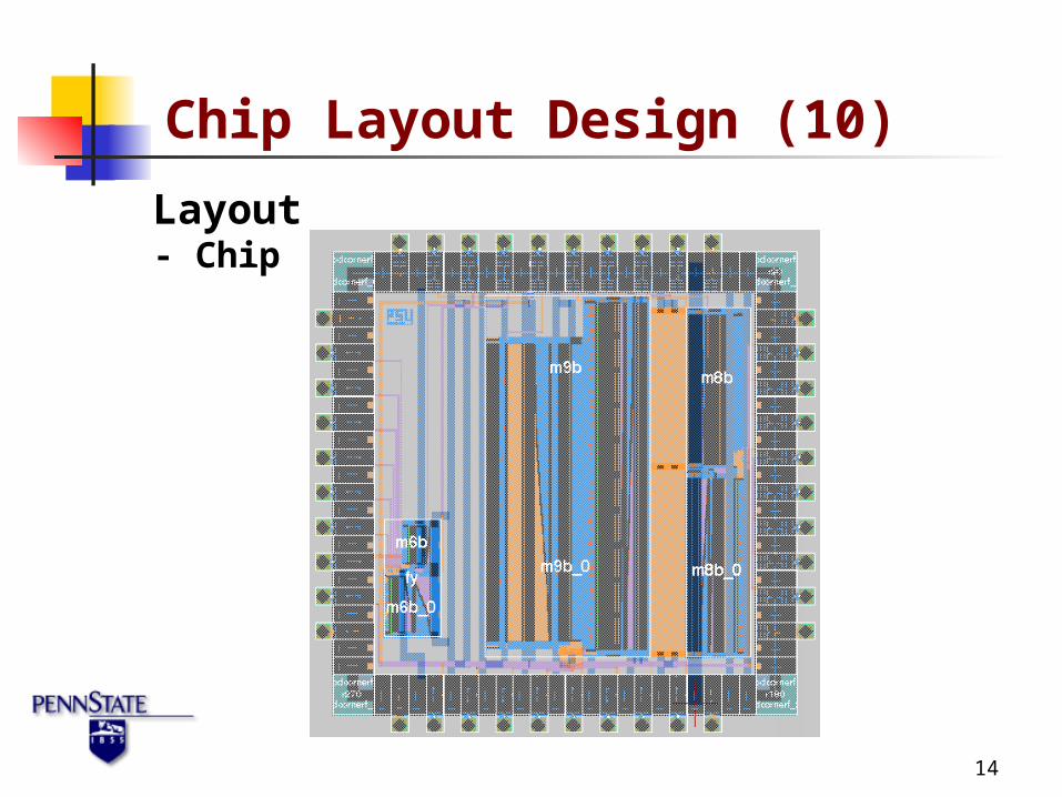
Dimension - ADCs
- Chip size (2580um * 2580um)
Chip Layout Design (2)
ADCs Size (W*H) um Area (mm2)
6bit high speed 198.740 * 256.350 0.051
6bit low power 289.840 * 352.350 0.102
8bit high speed 301.410 * 841.650 0.254
8bit low power 331.560 * 969.650 0.322
9bit high speed 339.720 * 1868.550 0.635
9bit low power 512.250 * 1612.550 0.826

7
Layout- 6bit (0.24 um)
Chip Layout Design (3)

8
Layout- 6bit (1.00 um)
Chip Layout Design (4)

9
Layout- 8bit (0.24 um)
Chip Layout Design (5)

10
Layout- 8bit (0.50 um)
Chip Layout Design (6)

11
Layout- 9bit (0.50 um)
Chip Layout Design (7)

12
Layout- 9bit (1.00 um)
Chip Layout Design (8)

13
Layout- Pad
Chip Layout Design (9)
14
Layout- Chip
Chip Layout Design (10)

15
Simulation Results (1)
ADCs
Max. Speed
(MSPS)
Max.
Current
(mA)
Avg.
Power
(mW)
Max.
Power
(mW)
6bit (0.24um) 1000 41.80 68.98 102.76
6bit (1.00um) 400 29.36 37.57 70.03
8bit (0.24um) 667 139.08 254.76 353.78
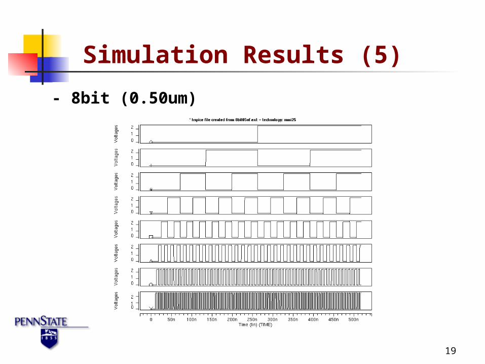
8bit (0.50um) 500 99.34 165.29 254.87
9bit (0.50um) 250 166.79 317.40 469.46
9bit (1.00um) 200 145.38 260.11 417.15
- pad delay : 0.864 ns

16
Simulation Results (2)
- 6bit (0.24um)

17
Simulation Results (3)
- 6bit (1.00um)

18
Simulation Results (4)
- 8bit (0.24um)
19
Simulation Results (5)
- 8bit (0.50um)

20
Simulation Results (6)
- 9bit (0.50um)

21
Simulation Results (7)
- 9bit (1.00um)

22
1. High Speed
2. Relatively small area
3. Relatively low-power
Features of the TIQ based ADC

23
1. Dynamic fine-tuning 2. Supply voltage variation compensation3. Temperature variation compensation4. Process variation compensation5. Lower power6. FIFO design for on-chip high-speed data
acquisition
Issues to Be Addressed in Future

24
• 2 GSPS with 0.18um CMOS• Custom layout CAD tool• 10bit and 12bit ADC• Low power• Dynamic calibration
• Offset• Gain• Temperature• Power supply voltage• Process parameter variation
Innovation Challenges
25
• High speed ADC for RF• ADC core - 6, 8 and 9 bit design
• first prototype chip (silicon test)• 0.25 m MOSIS (tsmc) process• CMOS digital logic technology
• Future ready• Dynamic calibration
Summary