quick circuit 5000: circuit board prototyping part ii
TRANSCRIPT
Quick Circuit 5000: Circuit Board Prototyping
Part IIGeoff Waldschmidt

22
Quick Circuit 5000
Creates single or double sided circuit boards by etching traces from copper clad circuit boards and drilling holes for vias.
Includes ISOPRO software for defining geometry and etching / drilling functions.
ISOPRO interfaces with Quick Circuit 5000 hardware to create the circuit board.
Quick Circuit precisely etches and drills the circuit board based on the geometry and drilling data supplied by ISOPRO.
Vias must be added manually using bailbars after the circuit board is etched and drilled.

33
Steps for Circuit Board Hardware
Ensure circuit board geometry and prototyping steps are defined in ISOPRO.
Inspect Quick Circuit 5000 hardware to ensure it is unimpeded and properly lubricated.
Install circuit board and backing material on the Quick Circuit platform.
Initialize the milling tool in ISOPRO.
Perform all drilling operations before etching or routing.– Install drill bit into Quick Circuit.– Select drilling operation to be performed in ISOPRO.– Execute operation with mill until completed.
Define next drilling or etching operation in ISOPRO, install correct bit, and execute mill.
Final operation should be routing which is used to cut the circuit board prototype from the circuit board bulk material.

44
Quick Circuit 5000 Hardware
Platform
Circuit Board
MillStepper Motor

55
Machine Settings
Machine settings defines the extent of the Quick Circuit platform (bed size).
Platform size is significant when determining where to place the circuit board layout in the ISOPRO software.
Circuit board bulk material may be used for multiple board prototypes.
The feed rate and spindle speed are also defined in machine settings dialogue.
Menu: Edit > Preferences
66
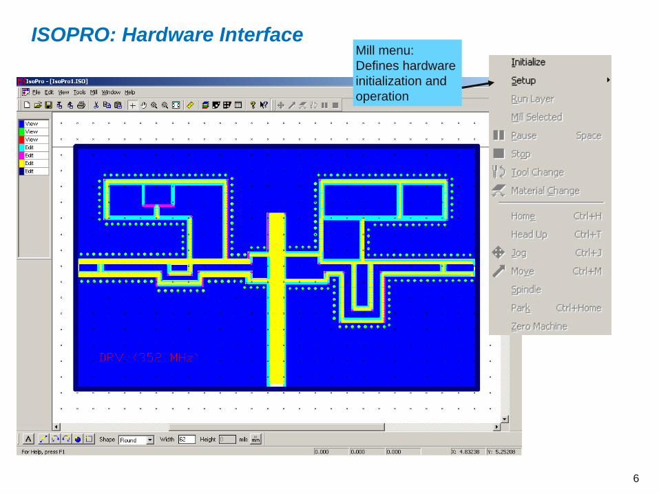
ISOPRO: Hardware InterfaceMill menu: Defines hardware initialization and operation

77
Adjustment Knobs
Mill height adjustment
knob
Mill foot adjustment
knob
Bit holderFoot pad
Solenoid
Height adjustment knob moves the entire mill relative to the Quick Circuit platform.
Foot adjustment knob moves only the foot pad relative to the Quick Circuit platform.
Mill force adjustment
knob
88
Setup for Drilling Via Holes
Mill > Initialize must be performed in order to setup the Quick Circuit hardware and determine the range of motion of the mill. This needs to be performed only once after the Quick Circuit is powered on.
Via holes should be drilled before any etching or routing is performed in order to prevent the copper cladding from curling.
Note that the setup and operation for routing (cutting the circuit board out of its bulk material) is identical to drilling except that a routing bit is used.
The mill should be moved to a position where the drill bit may be inserted by going to the menu item Mill > Jog.
Move the mill forward until it extends well beyond the edge of the Quick Circuit platform by using the arrow keys on the Jog dialogue window.
Remove the set screw on the bit holder using a hex tool. Be careful that any bit already in the holder does not fall out and become damaged.
Insert the required drill bit for the circuit board via holes.
Adjust the ‘mill height adjustment knob’ so that the bottom of the drill bit is above the circuit board material.
99
Drilling Via Holes
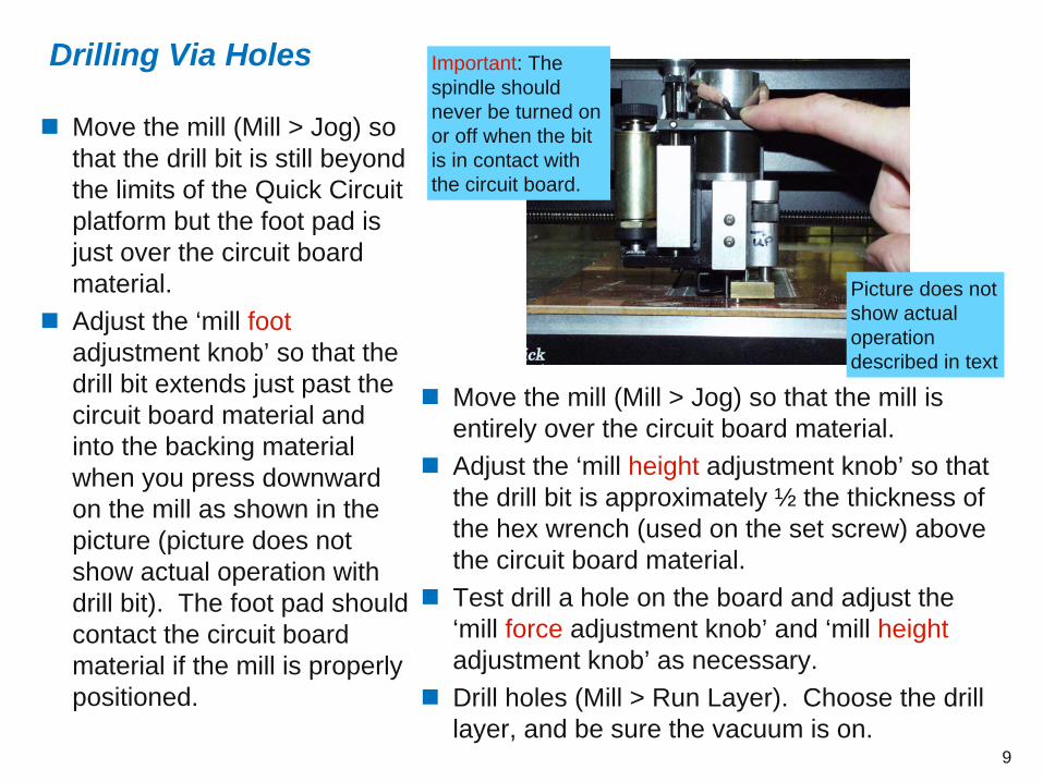
Move the mill (Mill > Jog) so that the drill bit is still beyond the limits of the Quick Circuit platform but the foot pad is just over the circuit board material.
Adjust the ‘mill foot adjustment knob’ so that the drill bit extends just past the circuit board material and into the backing material when you press downward on the mill as shown in the picture (picture does not show actual operation with drill bit). The foot pad should contact the circuit board material if the mill is properly positioned.
Move the mill (Mill > Jog) so that the mill is entirely over the circuit board material.
Adjust the ‘mill height adjustment knob’ so that the drill bit is approximately ½ the thickness of the hex wrench (used on the set screw) above the circuit board material.
Test drill a hole on the board and adjust the ‘mill force adjustment knob’ and ‘mill height adjustment knob’ as necessary.
Drill holes (Mill > Run Layer). Choose the drill layer, and be sure the vacuum is on.
Picture does not show actual operation described in text
Important: The spindle should never be turned on or off when the bit is in contact with the circuit board.

1010
Setup for Etching Traces
The mill should be moved to a position where the endmill bit may be inserted by going to the menu item Mill > Jog.
Move the mill forward until it extends well beyond the edge of the Quick Circuit platform by using the arrow keys on the Jog dialogue window.
Remove the set screw on the bit holder using a hex tool. Be careful that any bit already in the holder does not fall out and become damaged.
Insert the required endmill bit for the circuit board.
Adjust the ‘mill foot height adjustment knob’ so that the bottom of the foot pad is below the bottom of the endmill.
Adjust the ‘mill height adjustment knob’ so that the bottom of the endmill bit and Quick Circuit foot pad are above the circuit board material.
Move the mill (Mill > Jog) so that the endmill bit is over the circuit board material.

1111
Etching Traces
Push down on the mill as shown in the picture and slowly adjust the ‘mill foot height adjustment knob’ until the endmill just contacts the circuit board material. At this time, the bottom of the Quick Circuit foot pad and the endmill should be at identical heights. Release the mill.
Rotate the ‘mill foot height adjustment knob’ 2 or 3 clicks in the ‘down’ direction, i.e., opposite the ’up’ arrow written on the foot pad assembly.
Adjust the ‘mill height adjustment knob’ so that the endmill bit is approximately ¼ the thickness of the hex wrench (used on the set screw) above the circuit board material.
Adjust the downward force of the mill onto the circuit board material using the ‘mill force adjustment knob’ and using the key combination <ctrl> T. Adjust mill height if necessary.
Perform a trial etch (Mill > Jog) by moving the mill to an unused portion of the circuit board material, turning on the spindle head, lowering the head, and moving the mill horizontally for about two inches. Raise the head and turn off the spindle. Be sure the vacuum is on.
Inspect the circuit board material. If the etching is not deep enough or too deep, adjust the ‘mill foot height adjustment knob’ by another click until the results of the trial etch are satisfactory.
Etch traces (Mill > Run Layer). Choose the appropriate component layer, and be sure the vacuum is on.
Important: The spindle should never be turned on or off when the bit is in contact with the circuit board.
1212
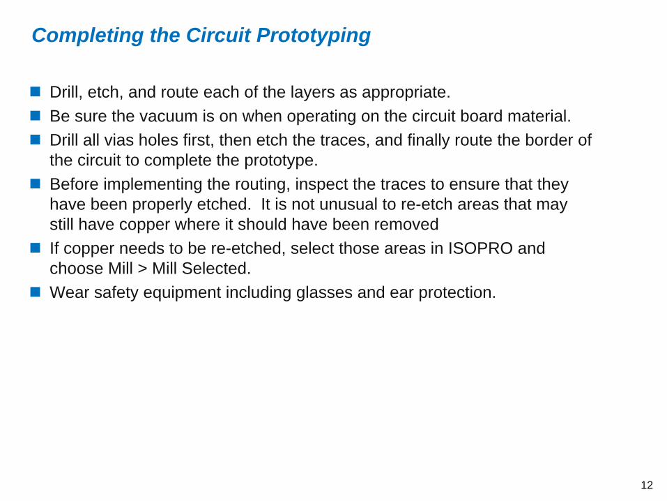
Completing the Circuit Prototyping
Drill, etch, and route each of the layers as appropriate.
Be sure the vacuum is on when operating on the circuit board material.
Drill all vias holes first, then etch the traces, and finally route the border of the circuit to complete the prototype.
Before implementing the routing, inspect the traces to ensure that they have been properly etched. It is not unusual to re-etch areas that may still have copper where it should have been removed
If copper needs to be re-etched, select those areas in ISOPRO and choose Mill > Mill Selected.
Wear safety equipment including glasses and ear protection.

1313
Example 1: Single Trace
1414
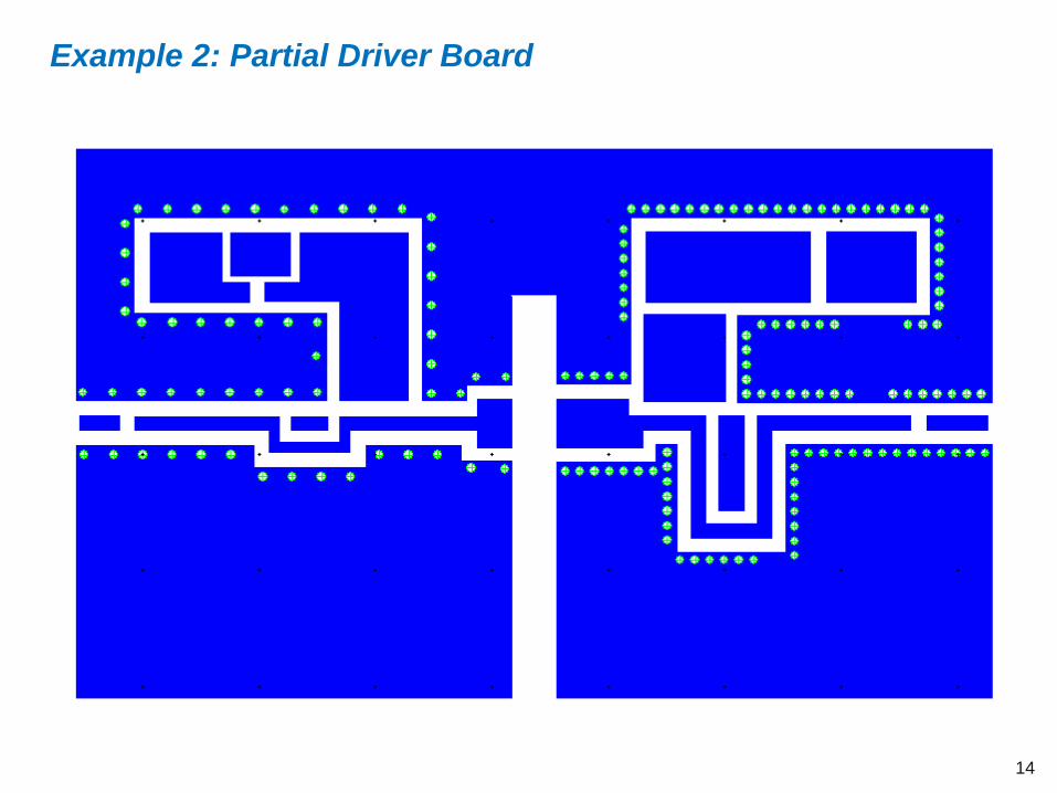
Example 2: Partial Driver Board