quick guide - tecdriver micro drive fc 51.pdf · fc 51 bussmann bussmann bussmann littel fuse ......
TRANSCRIPT
VLT® Micro Drive FC 51
Quick Guide
1. Quick Guide
1.1.1. Available Literature
NB!
This quick guide contains the basic information necessary for installing and running the VLT Micro Drive.
In case more information is needed, the below literature can be downloaded from
http://www.danfoss.com/BusinessAreas/DrivesSolutions/Documentations/Technical+Documentation.htm.
Title Literature no.VLT Micro Drive FC 51 Operating Instructions MG.02.AX.YYVLT Micro Drive FC 51 Quick Guide MG.02.BX.YYVLT Micro Drive FC 51 Programming Guide MG.02.CX.YYFC 51 LCP Mounting Instruction MI.02.AX.YYFC 51 De-coupling Plate Mounting Instruction MI.02.BX.YYFC 51 Remote Mounting Kit Mounting Instruction MI.02.CX.YYFC 51 DIN Rail Kit Mounting Instruction MI.02.DX.YYFC 51 IP21 Kit Mounting Instruction MI.02.EX.YYFC 51 Nema1 Kit Mounting Instruction MI.02.FX.YY
X = Revision number
Y = Language code
1.1.2. High Voltage Warning
The voltage of the frequency converter is dangerous whenever it is connected to mains. Incorrect installation of the motor or frequency
converter may cause damage to the equipment, serious injury or death. Consequently, it is essential to comply with the instructions
in this manual as well as local and national rules and safety regulations.
1.1.3. Safety Instructions
• Make sure the frequency converter is properly connected to earth.
• Do not remove mains connections, motor connections or other power connections while the frequency converter is connected to power.
• Protect users against supply voltage.
• Protect the motor against overloading according to national and local regulations.
• The earth leakage current exceeds 3.5 mA.
• The [OFF] key is not a safety switch. It does not disconnect the frequency converter from mains.
1.1.4. Approvals
Quick Guide for VLT Micro FC 51 1. Quick Guide
MG.02.B3.02 - VLT is a registered Danfoss trademark 1
1
1.1.5. General Warning
Warning:
Touching the electrical parts may be fatal - even after the equipment has been disconnected from mains.
Also make sure that other voltage inputs have been disconnected, (linkage of DC intermediate circuit).
Be aware that there may be high voltage on the DC link even when the LEDs are turned off.
Before touching any potentially live parts of the VLT Micro Drive, wait at least 4 minutes for all sizes.
Shorter time is allowed only if indicated on the nameplate for the specific unit.
Leakage Current
The earth leakage current from the VLT Micro Drive FC 51 exceeds 3.5 mA. According to IEC 61800-5-1 a reinforced Protective Earth
connection must be ensured by means of a min. 10mm² Cu or an addtional PE wire - with the same cable cross section as the Mains
wiring - must be terminated separately.
Residual Current Device
This product can cause a D.C. current in the protective conductor. Where a residual current device (RCD) is used for extra protection,
only an RCD of Type B (time delayed) shall be used on the supply side of this product. See also Danfoss Application Note on RCD, MN.
90.GX.YY.
Protective earthing of the VLT Micro Drive and the use of RCDs must always follow national and local regulations.
Motor overload protection is possible by setting Parameter 1-90 Motor thermal protection to the value ETR trip. For the North American
market: ETR functions provide class 20 motor overload protection, in accordance with NEC.
Installation in high altitudes:
By altitudes above 2km, please contact Danfoss Drives regarding PELV.
1.1.6. IT Mains
IT Mains
Installation on isolated mains source, i.e. IT mains.
Max. supply voltage allowed when connected to mains: 440 V.
As an option, Danfoss offers line filters for improved harmonics performance.
1.1.7. Avoid unintended Start
While the frequency converter is connected to mains, the motor can be started/stopped using digital commands, bus commands, references or via the
Local Control Panel.
• Disconnect the frequency converter from mains whenever personal safety considerations make it necessary to avoid unintended start of any
motors.
• To avoid unintended start, always activate the [OFF] key before changing parameters.
1. Quick Guide Quick Guide for VLT Micro FC 51
2 MG.02.B3.02 - VLT is a registered Danfoss trademark
1
1.1.8. Disposal Instruction
Equipment containing electrical components must not be disposed of together with domestic waste.
It must be separately collected with electrical and electronic waste according to local and currently valid leg-
islation.
1.1.9. Before Commencing Repair Work
1. Disconnect FC 51 from mains (and external DC supply, if present.)
2. Wait for 4 minutes for discharge of the DC-link.
3. Disconnect DC bus terminals and brake terminals (if present)
4. Remove motor cable
1.1.10. Side-by-Side Installation
The Danfoss VLT Micro Drive can be mounted side-by-side for IP 20 rating units and requires 100 mm clearance above and below for cooling. Please
refer to the specifications near the end of this document for details on environmental ratings of the VLT Micro FC 51.
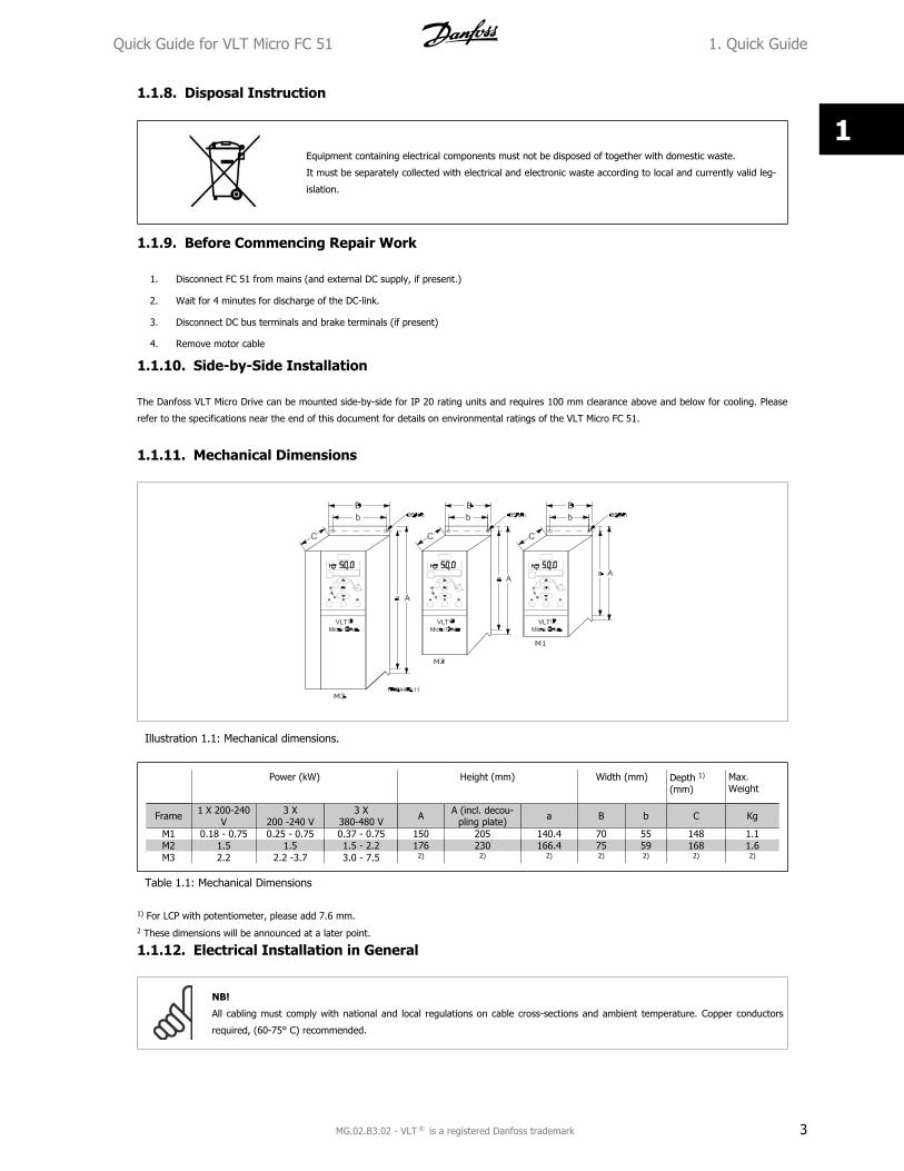
1.1.11. Mechanical Dimensions
Illustration 1.1: Mechanical dimensions.
Power (kW) Height (mm) Width (mm) Depth 1)
(mm)Max.Weight
Frame 1 X 200-240V
3 X200 -240 V
3 X380-480 V A A (incl. decou-
pling plate) a B b C Kg
M1 0.18 - 0.75 0.25 - 0.75 0.37 - 0.75 150 205 140.4 70 55 148 1.1M2 1.5 1.5 1.5 - 2.2 176 230 166.4 75 59 168 1.6M3 2.2 2.2 -3.7 3.0 - 7.5 2) 2) 2) 2) 2) 2) 2)
Table 1.1: Mechanical Dimensions
1) For LCP with potentiometer, please add 7.6 mm.2 These dimensions will be announced at a later point.
1.1.12. Electrical Installation in General
NB!
All cabling must comply with national and local regulations on cable cross-sections and ambient temperature. Copper conductors
required, (60-75° C) recommended.
Quick Guide for VLT Micro FC 51 1. Quick Guide
MG.02.B3.02 - VLT is a registered Danfoss trademark 3
1
Details of terminal tightening torques.
Power (kW) Torque (Nm)
Frame 1 x 200-240V
3 x 200-240V
3 x 380-480V Line Motor
DC connec-tion/Brake1)
Control Ter-minals Earth Relay
M1 0.18 - 0.75 0.25 - 0.75 0.37 - 0.75 1.4 0.7 - 0.15 3 0.5M2 1.5 1.5 1.5 - 2.2 1.4 0.7 - 0.15 3 0.5M3 2.2 2.2 - 3.7 3.0 - 7.5 1.4 0.7 - 0.15 3 0.5
1) Spade connectors
Table 1.2: Tightening of terminals.
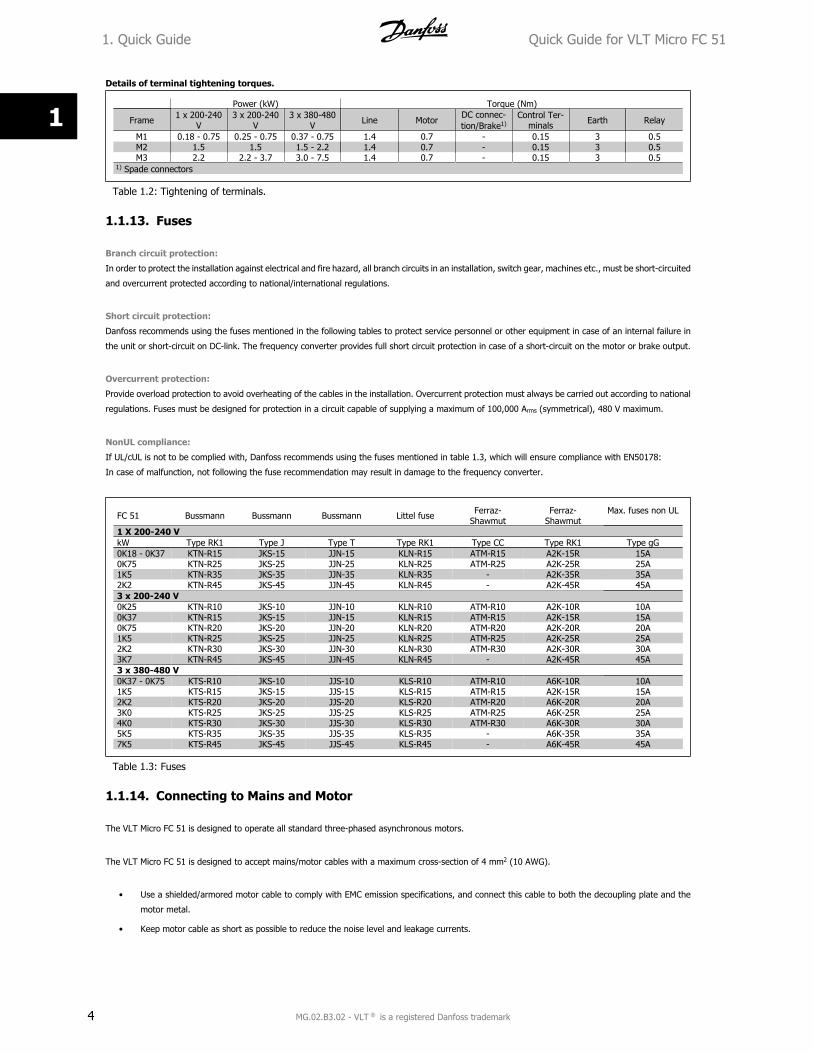
1.1.13. Fuses
Branch circuit protection:
In order to protect the installation against electrical and fire hazard, all branch circuits in an installation, switch gear, machines etc., must be short-circuited
and overcurrent protected according to national/international regulations.
Short circuit protection:
Danfoss recommends using the fuses mentioned in the following tables to protect service personnel or other equipment in case of an internal failure in
the unit or short-circuit on DC-link. The frequency converter provides full short circuit protection in case of a short-circuit on the motor or brake output.
Overcurrent protection:
Provide overload protection to avoid overheating of the cables in the installation. Overcurrent protection must always be carried out according to national
regulations. Fuses must be designed for protection in a circuit capable of supplying a maximum of 100,000 Arms (symmetrical), 480 V maximum.
NonUL compliance:
If UL/cUL is not to be complied with, Danfoss recommends using the fuses mentioned in table 1.3, which will ensure compliance with EN50178:
In case of malfunction, not following the fuse recommendation may result in damage to the frequency converter.
FC 51 Bussmann Bussmann Bussmann Littel fuse Ferraz-Shawmut
Ferraz-Shawmut
Max. fuses non UL
1 X 200-240 VkW Type RK1 Type J Type T Type RK1 Type CC Type RK1 Type gG0K18 - 0K37 KTN-R15 JKS-15 JJN-15 KLN-R15 ATM-R15 A2K-15R 15A0K75 KTN-R25 JKS-25 JJN-25 KLN-R25 ATM-R25 A2K-25R 25A1K5 KTN-R35 JKS-35 JJN-35 KLN-R35 - A2K-35R 35A2K2 KTN-R45 JKS-45 JJN-45 KLN-R45 - A2K-45R 45A3 x 200-240 V0K25 KTN-R10 JKS-10 JJN-10 KLN-R10 ATM-R10 A2K-10R 10A0K37 KTN-R15 JKS-15 JJN-15 KLN-R15 ATM-R15 A2K-15R 15A0K75 KTN-R20 JKS-20 JJN-20 KLN-R20 ATM-R20 A2K-20R 20A1K5 KTN-R25 JKS-25 JJN-25 KLN-R25 ATM-R25 A2K-25R 25A2K2 KTN-R30 JKS-30 JJN-30 KLN-R30 ATM-R30 A2K-30R 30A3K7 KTN-R45 JKS-45 JJN-45 KLN-R45 - A2K-45R 45A3 x 380-480 V0K37 - 0K75 KTS-R10 JKS-10 JJS-10 KLS-R10 ATM-R10 A6K-10R 10A1K5 KTS-R15 JKS-15 JJS-15 KLS-R15 ATM-R15 A2K-15R 15A2K2 KTS-R20 JKS-20 JJS-20 KLS-R20 ATM-R20 A6K-20R 20A3K0 KTS-R25 JKS-25 JJS-25 KLS-R25 ATM-R25 A6K-25R 25A4K0 KTS-R30 JKS-30 JJS-30 KLS-R30 ATM-R30 A6K-30R 30A5K5 KTS-R35 JKS-35 JJS-35 KLS-R35 - A6K-35R 35A7K5 KTS-R45 JKS-45 JJS-45 KLS-R45 - A6K-45R 45A
Table 1.3: Fuses
1.1.14. Connecting to Mains and Motor
The VLT Micro FC 51 is designed to operate all standard three-phased asynchronous motors.
The VLT Micro FC 51 is designed to accept mains/motor cables with a maximum cross-section of 4 mm2 (10 AWG).
• Use a shielded/armored motor cable to comply with EMC emission specifications, and connect this cable to both the decoupling plate and the
motor metal.
• Keep motor cable as short as possible to reduce the noise level and leakage currents.
1. Quick Guide Quick Guide for VLT Micro FC 51
4 MG.02.B3.02 - VLT is a registered Danfoss trademark
1
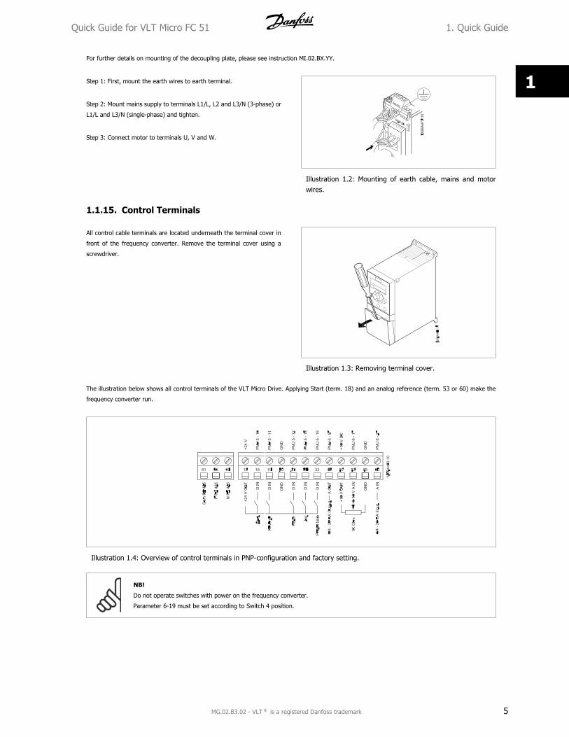
For further details on mounting of the decoupling plate, please see instruction MI.02.BX.YY.
Step 1: First, mount the earth wires to earth terminal.
Step 2: Mount mains supply to terminals L1/L, L2 and L3/N (3-phase) or
L1/L and L3/N (single-phase) and tighten.
Step 3: Connect motor to terminals U, V and W.
Illustration 1.2: Mounting of earth cable, mains and motorwires.
1.1.15. Control Terminals
All control cable terminals are located underneath the terminal cover in
front of the frequency converter. Remove the terminal cover using a
screwdriver.
Illustration 1.3: Removing terminal cover.
The illustration below shows all control terminals of the VLT Micro Drive. Applying Start (term. 18) and an analog reference (term. 53 or 60) make the
frequency converter run.
Illustration 1.4: Overview of control terminals in PNP-configuration and factory setting.
NB!
Do not operate switches with power on the frequency converter.
Parameter 6-19 must be set according to Switch 4 position.
Quick Guide for VLT Micro FC 51 1. Quick Guide
MG.02.B3.02 - VLT is a registered Danfoss trademark 5
1
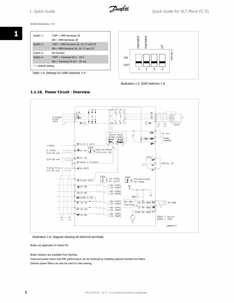
S200 Switches 1-4:
Switch 1: *OFF = PNP terminals 29
ON = NPN terminals 29
Switch 2: *OFF = PNP terminal 18, 19, 27 and 33
ON = NPN terminal 18, 19, 27 and 33
Switch 3: No function
Switch 4: *OFF = Terminal 53 0 - 10 V
ON = Terminal 53 0/4 - 20 mA
* = default setting
Table 1.4: Settings for S200 Switches 1-4
Illustration 1.5: S200 Switches 1-4.
1.1.16. Power Circuit - Overview
Illustration 1.6: Diagram showing all electrical terminals.
Brake not applicable for frame M1.
Brake resistors are available from Danfoss.
Improved power factor and EMC performance can be achieved by installing optional Danfoss line filters.
Danfoss power filters can also be used for load sharing.
1. Quick Guide Quick Guide for VLT Micro FC 51
6 MG.02.B3.02 - VLT is a registered Danfoss trademark
1
1.1.17. Load sharing/Brake
Use 6.3 mm insulated Faston Plugs designed for high voltage for DC (Load Sharing and brake).
Contact Danfoss or see instruction no. MI.50.Nx.02 for load sharing and instruction no. MI.90.Fx.02 for brake.
Load sharing: Connect terminals UDC- and UDC/BR+.
Brake: Connect terminals BR- and UDC/BR+.
Note that voltage levels of up to 850 V DC may occur between terminals
UDC+/BR+ and UDC-. Not short circuit protected.
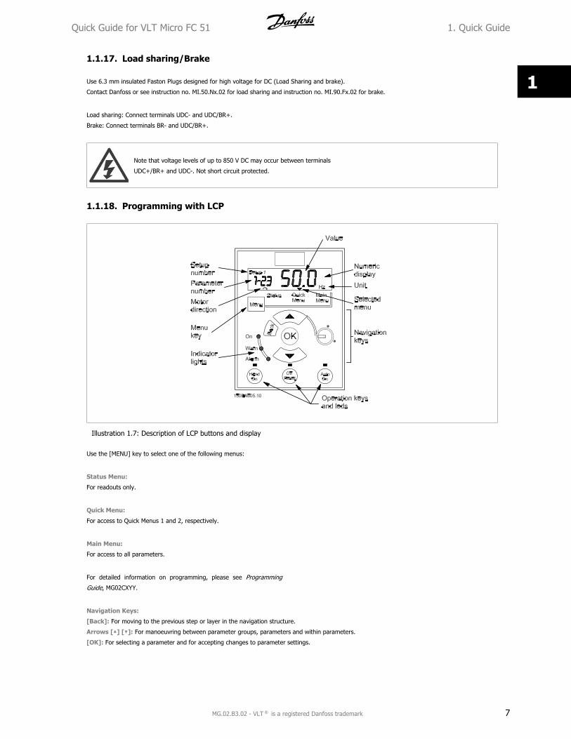
1.1.18. Programming with LCP
Illustration 1.7: Description of LCP buttons and display
Use the [MENU] key to select one of the following menus:
Status Menu:
For readouts only.
Quick Menu:
For access to Quick Menus 1 and 2, respectively.
Main Menu:
For access to all parameters.
For detailed information on programming, please see Programming
Guide, MG02CXYY.
Navigation Keys:
[Back]: For moving to the previous step or layer in the navigation structure.
Arrows [ ] [ ]: For manoeuvring between parameter groups, parameters and within parameters.
[OK]: For selecting a parameter and for accepting changes to parameter settings.
Quick Guide for VLT Micro FC 51 1. Quick Guide
MG.02.B3.02 - VLT is a registered Danfoss trademark 7
1
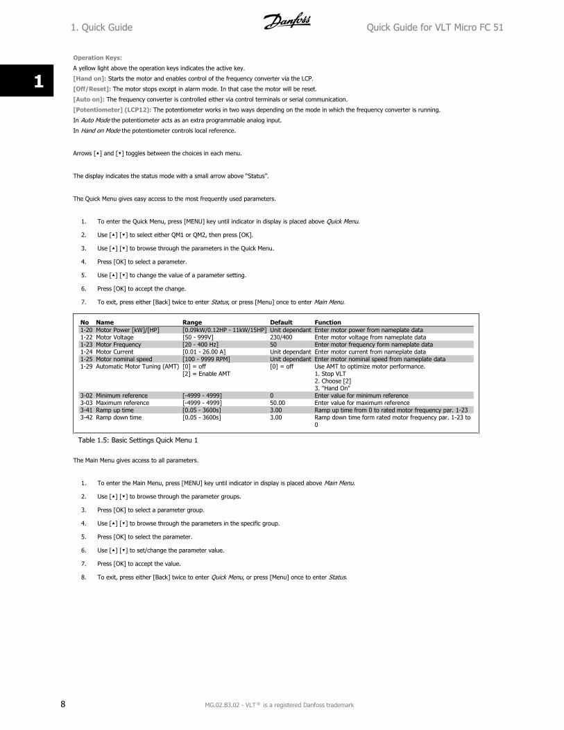
Operation Keys:
A yellow light above the operation keys indicates the active key.
[Hand on]: Starts the motor and enables control of the frequency converter via the LCP.
[Off/Reset]: The motor stops except in alarm mode. In that case the motor will be reset.
[Auto on]: The frequency converter is controlled either via control terminals or serial communication.
[Potentiometer] (LCP12): The potentiometer works in two ways depending on the mode in which the frequency converter is running.
In Auto Mode the potentiometer acts as an extra programmable analog input.
In Hand on Mode the potentiometer controls local reference.
Arrows [ ] and [ ] toggles between the choices in each menu.
The display indicates the status mode with a small arrow above “Status”.
The Quick Menu gives easy access to the most frequently used parameters.
1. To enter the Quick Menu, press [MENU] key until indicator in display is placed above Quick Menu.
2. Use [ ] [ ] to select either QM1 or QM2, then press [OK].
3. Use [ ] [ ] to browse through the parameters in the Quick Menu.
4. Press [OK] to select a parameter.
5. Use [ ] [ ] to change the value of a parameter setting.
6. Press [OK] to accept the change.
7. To exit, press either [Back] twice to enter Status, or press [Menu] once to enter Main Menu.
No Name Range Default Function1-20 Motor Power [kW]/[HP] [0.09kW/0.12HP - 11kW/15HP] Unit dependant Enter motor power from nameplate data1-22 Motor Voltage [50 - 999V] 230/400 Enter motor voltage from nameplate data1-23 Motor Frequency [20 - 400 Hz] 50 Enter motor frequency form nameplate data1-24 Motor Current [0.01 - 26.00 A] Unit dependant Enter motor current from nameplate data1-25 Motor nominal speed [100 - 9999 RPM] Unit dependant Enter motor nominal speed from nameplate data1-29 Automatic Motor Tuning (AMT) [0] = off
[2] = Enable AMT[0] = off Use AMT to optimize motor performance.
1. Stop VLT2. Choose [2]3. "Hand On"
3-02 Minimum reference [-4999 - 4999] 0 Enter value for minimum reference3-03 Maximum reference [-4999 - 4999] 50.00 Enter value for maximum reference3-41 Ramp up time [0.05 - 3600s] 3.00 Ramp up time from 0 to rated motor frequency par. 1-233-42 Ramp down time [0.05 - 3600s] 3.00 Ramp down time form rated motor frequency par. 1-23 to
0
Table 1.5: Basic Settings Quick Menu 1
The Main Menu gives access to all parameters.
1. To enter the Main Menu, press [MENU] key until indicator in display is placed above Main Menu.
2. Use [ ] [ ] to browse through the parameter groups.
3. Press [OK] to select a parameter group.
4. Use [ ] [ ] to browse through the parameters in the specific group.
5. Press [OK] to select the parameter.
6. Use [ ] [ ] to set/change the parameter value.
7. Press [OK] to accept the value.
8. To exit, press either [Back] twice to enter Quick Menu, or press [Menu] once to enter Status.
1. Quick Guide Quick Guide for VLT Micro FC 51
8 MG.02.B3.02 - VLT is a registered Danfoss trademark
1
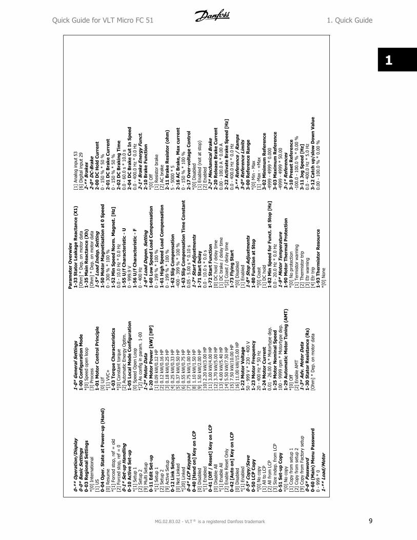
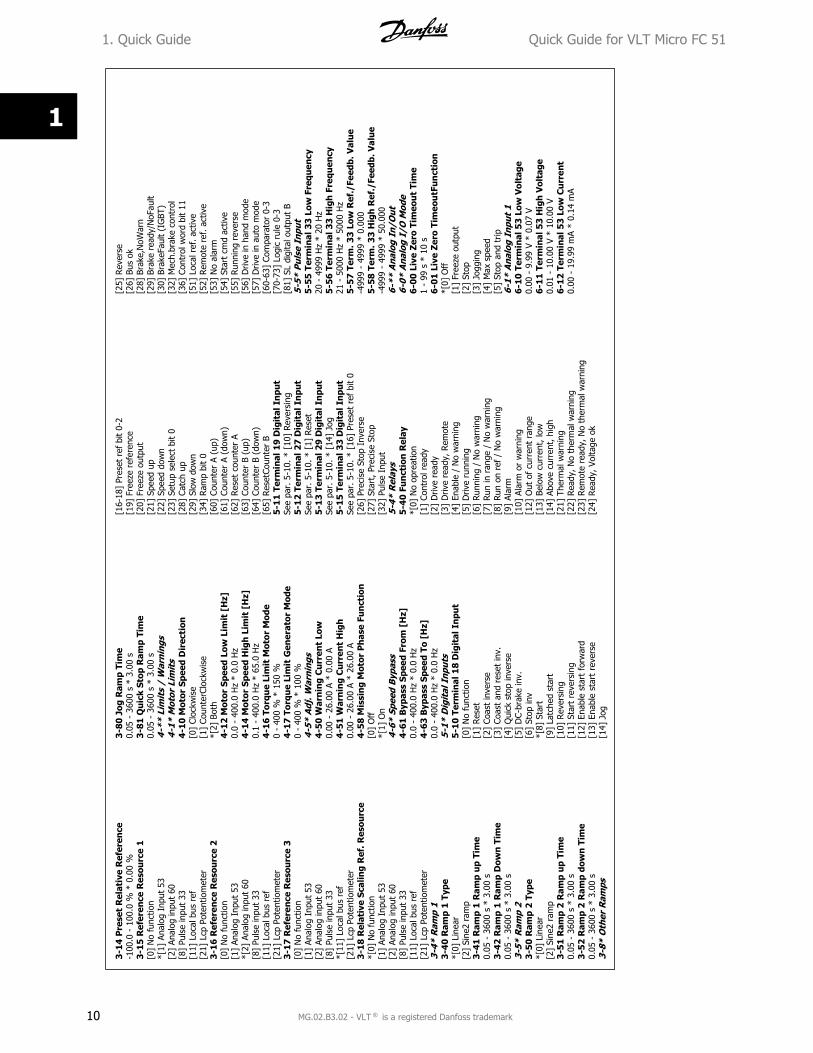
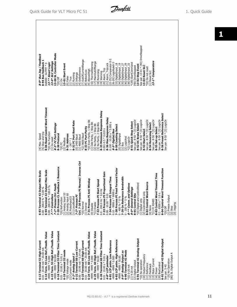
Par
amet
er O
verw
iev
0-**
Ope
rati
on/D
ispl
ay0-
0* B
asic
Set
ting
s0-
03 R
egio
nal
Set
ting
s*[
0] I
nter
natio
nal
[1]
US
0-0
4 O
per.
Sta
te a
t P
ower
-up
(Han
d)[0
] Res
ume
*[1]
For
ced
stop
, ref
= o
ld[2
] Fo
rced
sto
p, r
ef =
00-
1* S
et-u
p H
andl
ing
0-10
Act
ive
Set-
up
*[1]
Set
up 1
[2]
Setu
p 2
[9]
Mul
ti Se
tup
0-11
Edi
t Se
t-u
p*[
1] S
etup
1[2
] Se
tup
2[9
] Ac
tive
Setu
p0-
12 L
ink
Setu
ps[0
] N
ot L
inke
d*[
20]
Link
ed0-
4* L
CP K
eypa
d0-
40
[H
and
on]
Key
on
LC
P[0
] D
isab
led
*[1]
Ena
bled
0-41
[O
ff /
Res
et]
Key
on
LC
P[0
] D
isab
le A
ll*[
1] E
nabl
e Al
l[2
] En
able
Res
et O
nly
0-4
2 [
Au
to o
n] K
ey o
n L
CP
[0]
Dis
able
d*[
1] E
nabl
ed0-
5* C
opy/
Save
0-50
LC
P C
opy
*[0]
No
copy
[1]
All t
o LC
P[2
] Al
l fro
m L
CP[3
] Si
ze in
dep.
fro
m L
CP0-
51 S
et-u
p C
opy
*[0]
No
copy
[1]
Copy
fro
m s
etup
1[2
] Co
py f
rom
set
up 2
[9]
Copy
fro
m F
acto
ry s
etup
0-6*
Pas
swor
d0
-60
(M
ain
) M
enu
Pas
swor
d0
- 99
9 *
01-
** L
oad/
Mot
or
1-0*
Gen
eral
Set
ting
s1-
00 C
onfi
gura
tion
Mod
e*[
0] S
peed
ope
n lo
op[3
] Pr
oces
s1-
01 M
otor
Con
trol
Pri
ncip
le[0
] U
/f*[
1] V
VC+
1-03
Tor
que
Ch
arac
teri
stic
s*[
0] C
onst
ant
torq
ue[2
] Au
tom
atic
Ene
rgy
Opt
im.
1-05
Loc
al M
ode
Con
figu
rati
on[0
] Sp
eed
Ope
n Lo
op*[
2] A
s co
nfig
in p
aram
. 1-0
01-
2* M
otor
Dat
a1-
20 M
otor
Pow
er [
kW]
[HP
][1
] 0.
09 k
W/0
.12
HP
[2]
0.12
kW
/0.1
6 H
P[3
] 0.
18 k
W/0
.25
HP
[4]
0.25
kW
/0.3
3 H
P[5
] 0.
37 k
W/0
.50
HP
[6]
0.55
kW
/0.7
5 H
P[7
] 0.
75 k
W/1
.00
HP
[8]
1.10
kW
/1.5
0 H
P[9
] 1.
50 k
W/2
.00
HP
[10]
2.2
0 kW
/3.0
0 H
P[1
1] 3
.00
kW/4
.00
HP
[12]
3.7
0 kW
/5.0
0 H
P[1
3] 4
.00
kW/5
.40
HP
[14]
5.5
0 kW
/7.5
0 H
P[1
5] 7
.50
kW/1
0.00
HP
[16]
11.
00 k
W/1
5.00
HP
1-22
Mot
or V
olta
ge50
- 9
99 V
* 2
30 -
400
V1-
23 M
otor
Fre
quen
cy20
- 4
00 H
z *
50 H
z1-
24 M
otor
Cu
rren
t0.
01 -
26.
00 A
* M
otor
type
dep
.1-
25 M
otor
Nom
inal
Spe
ed10
0 -
9999
rpm
* M
otor
type
dep
.1
-29
Au
tom
atic
Mot
or T
un
ing
(AM
T)*[
0] O
ff[2
] En
able
AM
T1-
3* A
dv. M
otor
Dat
a1
-30
Sta
tor
Res
ista
nce
(R
s)[O
hm]
* D
ep. o
n m
otor
dat
a
1-3
3 S
tato
r Le
akag
e R
eact
ance
(X
1)
[Ohm
] *
Dep
. on
mot
or d
ata
1-35
Mai
n R
eact
ance
(X
h)
[Ohm
] *
Dep
. on
mot
or d
ata
1-5*
Loa
d In
dep.
Set
ting
1-50
Mot
or M
agn
etis
atio
n a
t 0
Spee
d0
- 30
0 %
* 1
00 %
1-52
Min
Spe
ed N
orm
. Mag
net
. [H
z]0.
0 -
10.0
Hz
* 0.
0 H
z1-
55 U
/f C
har
acte
rist
ic -
U0
- 99
9.9
V1-
56 U
/f C
har
acte
rist
ic -
F0
- 40
0 H
z1-
6* L
oad
Dep
en. S
etti
ng1-
60 L
ow S
peed
Loa
d C
ompe
nsa
tion
0 -
199
% *
100
%1-
61 H
igh
Spe
ed L
oad
Com
pen
sati
on0
- 19
9 %
* 1
00 %
1-62
Slip
Com
pen
sati
on-4
00 -
399
% *
100
%1-
63 S
lip C
ompe
nsa
tion
Tim
e C
onst
ant
0.05
- 5
.00
s *
0.10
s1-
7* S
tart
Adj
ustm
ents
1-71
Sta
rt D
elay
0.0
- 10
.0 s
* 0
.0 s
1-72
Sta
rt F
un
ctio
n[0
] D
C ho
ld /
del
ay t
ime
[1]
DC
brak
e /
dela
y tim
e*[
2] C
oast
/ d
elay
tim
e1-
73 F
lyin
g St
art
*[0]
Dis
able
d[1
] En
able
d1-
8* S
top
Adj
ustm
ents
1-80
Fu
nct
ion
at
Stop
*[0]
Coa
st[1
] D
C ho
ld1-
82 M
in S
peed
for
Fu
nct
. at
Stop
[H
z]0.
0 -
20.0
Hz
* 0.
0 H
z1-
9* M
otor
Tem
pera
ture
1-90
Mot
or T
herm
al P
rote
ctio
n*[
0] N
o pr
otec
tion
[1]
Term
isto
r w
arni
ng[2
] Th
erm
isto
r tr
ip[3
] Et
r w
arni
ng[4
] Et
r tr
ip1-
93 T
her
mis
tor
Res
ourc
e*[
0] N
one
[1]
Anal
og in
put
53[6
] D
igita
l inp
ut 2
92-
** B
rake
s2-
0* D
C-B
rake
2-00
DC
Hol
d C
urr
ent
0 -
150
% *
50
%2-
01 D
C B
rake
Cu
rren
t0
- 15
0 %
* 5
0 %
2-02
DC
Bra
kin
g Ti
me
0.0
- 60
.0 s
* 1
0.0
s2-
04 D
C B
rake
Cu
t In
Spe
ed0.
0 -
400.
0 H
z *
0.0
Hz
2-1*
Bra
ke E
nerg
y Fu
nct.
2-10
Bra
ke F
un
ctio
n*[
0] O
ff[1
] Res
isto
r br
ake
[2]
AC b
rake
2-11
Bra
ke R
esis
tor
(oh
m)
5 -
5000
* 5
2-16
AC
Bra
ke, M
ax c
urr
ent
0 -
150
% *
100
%2-
17 O
ver-
volt
age
Con
trol
*[0]
Dis
able
d[1
] En
able
d (n
ot a
t st
op)
[2]
Enab
led
2-2*
Mec
hani
cal B
rake
2-20
Rel
ease
Bra
ke C
urr
ent
0.00
- 1
00.0
A *
0.0
0 A
2-22
Act
ivat
e B
rake
Spe
ed [
Hz]
0.0
- 40
0.0
Hz
* 0.
0 H
z3-
** R
efer
ence
/ R
amps
3-0*
Ref
eren
ce L
imit
s3-
00 R
efer
ence
Ran
ge*[
0] M
in -
Max
[1]
-Max
- +
Max
3-02
Min
imu
m R
efer
ence
-499
9 -
4999
* 0
.000
3-03
Max
imu
m R
efer
ence
-499
9 -
4999
* 5
0.00
3-1*
Ref
eren
ces
3-10
Pre
set
Ref
eren
ce-1
00.0
- 1
00.0
% *
0.0
0 %
3-11
Jog
Spe
ed [
Hz]
0.0
- 40
0.0
Hz
* 5.
0 H
z3
-12
Cat
ch u
p/sl
ow D
own
Val
ue
0.00
- 1
00.0
% *
0.0
0 %
Quick Guide for VLT Micro FC 51 1. Quick Guide
MG.02.B3.02 - VLT is a registered Danfoss trademark 9
1
3-14
Pre
set
Rel
ativ
e R
efer
ence
-100
.0 -
100
.0 %
* 0
.00
%3-
15 R
efer
ence
Res
ourc
e 1
[0]
No
func
tion
*[1]
Ana
log
Inpu
t 53
[2]
Anal
og in
put
60[8
] Pu
lse
inpu
t 33
[11]
Loc
al b
us r
ef[2
1] L
cp P
oten
tiom
eter
3-16
Ref
eren
ce R
esou
rce
2[0
] N
o fu
nctio
n[1
] An
alog
Inp
ut 5
3*[
2] A
nalo
g in
put
60[8
] Pu
lse
inpu
t 33
[11]
Loc
al b
us r
ef[2
1] L
cp P
oten
tiom
eter
3-17
Ref
eren
ce R
esou
rce
3[0
] N
o fu
nctio
n[1
] An
alog
Inp
ut 5
3[2
] An
alog
inpu
t 60
[8]
Puls
e in
put
33*[
11]
Loca
l bus
ref
[21]
Lcp
Pot
entio
met
er3-
18 R
elat
ive
Scal
ing
Ref
. Res
ourc
e*[
0] N
o fu
nctio
n[1
] An
alog
Inp
ut 5
3[2
] An
alog
inpu
t 60
[8]
Puls
e in
put
33[1
1] L
ocal
bus
ref
[21]
Lcp
Pot
entio
met
er3-
4* R
amp
13-
40 R
amp
1 T
ype
*[0]
Lin
ear
[2]
Sine
2 ra
mp
3-41
Ram
p 1
Ram
p u
p Ti
me
0.05
- 3
600
s *
3.00
s3-
42 R
amp
1 R
amp
Dow
n T
ime
0.05
- 3
600
s *
3.00
s3-
5* R
amp
23-
50 R
amp
2 T
ype
*[0]
Lin
ear
[2]
Sine
2 ra
mp
3-51
Ram
p 2
Ram
p u
p Ti
me
0.05
- 3
600
s *
3.00
s3-
52 R
amp
2 R
amp
dow
n T
ime
0.05
- 3
600
s *
3.00
s3-
8* O
ther
Ram
ps
3-8
0 Jo
g R
amp
Tim
e0.
05 -
360
0 s
* 3.
00 s
3-8
1 Q
uic
k St
op R
amp
Tim
e0.
05 -
360
0 s
* 3.
00 s
4-**
Lim
its
/ W
arni
ngs
4-1*
Mot
or L
imit
s4
-10
Mot
or S
peed
Dir
ecti
on[0
] Cl
ockw
ise
[1]
Coun
terC
lock
wis
e*[
2] B
oth
4-1
2 M
otor
Spe
ed L
ow L
imit
[H
z]0.
0 -
400.
0 H
z *
0.0
Hz
4-1
4 M
otor
Spe
ed H
igh
Lim
it [
Hz]
0.1
- 40
0.0
Hz
* 65
.0 H
z4
-16
Torq
ue
Lim
it M
otor
Mod
e0
- 40
0 %
* 1
50 %
4-1
7 To
rqu
e Li
mit
Gen
erat
or M
ode
0 -
400
% *
100
%4-
5* A
dj. W
arni
ngs
4-5
0 W
arn
ing
Cu
rren
t Lo
w0.
00 -
26.
00 A
* 0
.00
A4
-51
War
nin
g C
urr
ent
Hig
h0.
00 -
26.
00 A
* 2
6.00
A4
-58
Mis
sin
g M
otor
Ph
ase
Fun
ctio
n[0
] O
ff*[
1] O
n4-
6* S
peed
Byp
ass
4-6
1 B
ypas
s Sp
eed
From
[H
z]0.
0 -
400.
0 H
z *
0.0
Hz
4-6
3 B
ypas
s Sp
eed
To [
Hz]
0.0
- 40
0.0
Hz
* 0.
0 H
z5-
1* D
igit
al I
nput
s5
-10
Term
inal
18
Dig
ital
In
put
[0]
No
func
tion
[1]
Res
et[2
] Co
ast
inve
rse
[3]
Coas
t an
d re
set
inv.
[4]
Qui
ck s
top
inve
rse
[5]
DC-
brak
e in
v.[6
] St
op in
v*[
8] S
tart
[9]
Latc
hed
star
t[1
0] R
ever
sing
[11]
Sta
rt r
ever
sing
[12]
Ena
ble
star
t fo
rwar
d[1
3] E
nabl
e st
art
reve
rse
[14]
Jog
[16-
18]
Pres
et r
ef b
it 0-
2[1
9] F
reez
e re
fere
nce
[20]
Fre
eze
outp
ut[2
1] S
peed
up
[22]
Spe
ed d
own
[23]
Set
up s
elec
t bi
t 0
[28]
Cat
ch u
p[2
9] S
low
dow
n[3
4] R
amp
bit
0[6
0] C
ount
er A
(up
)[6
1] C
ount
er A
(do
wn)
[62]
Res
et c
ount
er A
[63]
Cou
nter
B (
up)
[64]
Cou
nter
B (
dow
n)[6
5] R
eset
Coun
ter
B5-
11
Term
inal
19
Dig
ital
In
put
See
par.
5-1
0. *
[10
] Re
vers
ing
5-1
2 Te
rmin
al 2
7 D
igit
al I
npu
tSe
e pa
r. 5
-10.
* [
1] R
eset
5-1
3 Te
rmin
al 2
9 D
igit
al I
npu
tSe
e pa
r. 5
-10.
* [
14]
Jog
5-1
5 Te
rmin
al 3
3 D
igit
al I
npu
tSe
e pa
r. 5
-10.
* [
16]
Pres
et r
ef b
it 0
[26]
Pre
cise
Sto
p In
vers
e[2
7] S
tart
, Pre
cise
Sto
p[3
2] P
ulse
Inp
ut5-
4* R
elay
s5-
40
Fun
ctio
n R
elay
*[0]
No
opre
atio
n[1
] Co
ntro
l rea
dy[2
] D
rive
read
y[3
] D
rive
read
y, R
emot
e[4
] En
able
/ N
o w
arni
ng[5
] D
rive
runn
ing
[6]
Run
ning
/ N
o w
arni
ng[7
] Run
in r
ange
/ N
o w
arni
ng[8
] Ru
n on
ref
/ N
o w
arni
ng[9
] Al
arm
[10]
Ala
rm o
r w
arni
ng[1
2] O
ut o
f cu
rren
t ra
nge
[13]
Bel
ow c
urre
nt, l
ow[1
4] A
bove
cur
rent
, hig
h[2
1] T
herm
al w
arni
ng[2
2] R
eady
, No
ther
mal
war
ning
[23]
Rem
ote
read
y, N
o th
erm
al w
arni
ng[2
4] R
eady
, Vol
tage
ok
[25]
Rev
erse
[26]
Bus
ok
[28]
Bra
ke,N
oWar
n[2
9] B
rake
rea
dy/N
oFau
lt[3
0] B
rake
Faul
t (I
GBT
)[3
2] M
ech.
brak
e co
ntro
l[3
6] C
ontr
ol w
ord
bit
11[5
1] L
ocal
ref
. act
ive
[52]
Rem
ote
ref. a
ctiv
e[5
3] N
o al
arm
[54]
Sta
rt c
md
activ
e[5
5] R
unni
ng r
ever
se[5
6] D
rive
in h
and
mod
e[5
7] D
rive
in a
uto
mod
e[6
0-63
] Co
mpa
rato
r 0-
3[7
0-73
] Lo
gic
rule
0-3
[81]
SL
digi
tal o
utpu
t B
5-5*
Pul
se I
nput
5-5
5 Te
rmin
al 3
3 Lo
w F
requ
ency
20 -
499
9 H
z *
20 H
z5
-56
Term
inal
33
Hig
h F
requ
ency
21 -
500
0 H
z *
5000
Hz
5-5
7 Te
rm. 3
3 Lo
w R
ef./
Feed
b. V
alu
e-4
999
- 49
99 *
0.0
005
-58
Term
. 33
Hig
h R
ef./
Feed
b. V
alu
e-4
999
- 49
99 *
50.
000
6-**
Ana
log
In/O
ut6-
0* A
nalo
g I/
O M
ode
6-0
0 Li
ve Z
ero
Tim
eou
t Ti
me
1 -
99 s
* 1
0 s
6-0
1 Li
ve Z
ero
Tim
eou
tFu
nct
ion
*[0]
Off
[1]
Free
ze o
utpu
t[2
] St
op[3
] Jo
ggin
g[4
] M
ax s
peed
[5]
Stop
and
trip
6-1*
Ana
log
Inpu
t 1
6-1
0 Te
rmin
al 5
3 Lo
w V
olta
ge0.
00 -
9.9
9 V
* 0.
07 V
6-1
1 Te
rmin
al 5
3 H
igh
Vol
tage
0.01
- 1
0.00
V *
10.
00 V
6-1
2 Te
rmin
al 5
3 Lo
w C
urr
ent
0.00
- 1
9.99
mA
* 0.
14 m
A
1. Quick Guide Quick Guide for VLT Micro FC 51
10 MG.02.B3.02 - VLT is a registered Danfoss trademark
1
6-13
Ter
min
al 5
3 H
igh
Cu
rren
t0.
01 -
20.
00 m
A *
20.0
0 m
A6-
14 T
erm
. 53
Low
Ref
./Fe
edb.
Val
ue
-499
9 -
4999
* 0
.000
6-15
Ter
m. 5
3 H
igh
Ref
./Fe
edb.
Val
ue
-499
9 -
4999
* 5
0.00
06-
16 T
erm
inal
53
Filt
er T
ime
Con
stan
t0.
01 -
10.
00 s
* 0
.01
s6-
19 T
erm
inal
53
mod
e*[
0] V
olta
ge m
ode
[1]
Curr
ent
mod
e6-
2* A
nalo
g In
put
26
-22
Ter
min
al 6
0 Lo
w C
urr
ent
0.00
- 1
9.99
mA
* 0.
14 m
A6-
23 T
erm
inal
60
Hig
h C
urr
ent
0.01
- 2
0.00
mA
* 20
.00
mA
6-24
Ter
m. 6
0 Lo
w R
ef./
Feed
b. V
alu
e-4
999
- 49
99 *
0.0
006-
25 T
erm
. 60
Hig
h R
ef./
Feed
b. V
alu
e-4
999
- 49
99 *
50.
006-
26 T
erm
inal
60
Filt
er T
ime
Con
stan
t0.
01 -
10.
00 s
* 0
.01
s6-
8* L
CP p
otm
eter
6-81
LC
P p
otm
. Low
Ref
eren
ce-4
999
- 49
99 *
0.0
006-
82 L
CP
pot
m. H
igh
Ref
eren
ce-4
999
- 49
99 *
50.
006-
9* A
nalo
g O
utpu
t xx
6-90
Ter
min
al 4
2 M
ode
*[0]
0-2
0 m
A[1
] 4-
20 m
A[2
] D
igita
l Out
put
6-91
Ter
min
al 4
2 A
nal
og O
utp
ut
*[0]
No
oper
atio
n[1
0] O
utpu
t Fr
eque
ncy
[11]
Ref
eren
ce[1
2] F
eedb
ack
[13]
Mot
or C
urre
nt[1
6] P
ower
[20]
Bus
Cont
rol
6-92
Ter
min
al 4
2 D
igit
al O
utp
ut
See
par.
5-4
0*
[0]
No
Ope
ratio
n[8
0] S
L D
igita
l Out
put
A
6-93
Ter
min
al 4
2 O
utp
ut
Min
Sca
le0.
00 -
200
.0 %
* 0
.00
%6-
94 T
erm
inal
42
Ou
tpu
t M
ax S
cale
0.00
- 2
00.0
% *
100
.0 %
7-**
Con
trol
lers
7-2*
Pro
cess
Ctr
l. Fe
edb
7-20
Pro
cess
CL
Feed
back
1 R
esou
rce
*[0]
NoF
unct
ion
[1]
Anal
og I
nput
53
[2]
Anal
og in
put
60[8
] Pu
lseI
nput
33[1
1] L
ocal
BusR
ef7-
3* P
roce
ss P
IC
trl.
7-3
0 P
roce
ss P
I N
orm
al/
Inve
rse
Ctr
l*[
0] N
orm
al[1
] In
vers
e7-
31 P
roce
ss P
I A
nti
Win
dup
[0]
Dis
able
*[1]
Ena
ble
7-32
Pro
cess
PI
Star
t Sp
eed
0.0
- 20
0.0
Hz
* 0.
0 H
z7-
33
Pro
cess
PI
Pro
port
ion
al G
ain
0.00
- 1
0.00
* 0
.01
7-34
Pro
cess
PI
Inte
gral
Tim
e0.
10 -
999
9 s
* 99
99 s
7-38
Pro
cess
PI
Feed
For
war
d Fa
ctor
0 -
400
% *
0 %
7-3
9 O
n R
efer
ence
Ban
dwid
th0
- 20
0 %
* 5
%8-
** C
omm
. and
Opt
ions
8-0*
Gen
eral
Set
ting
s8-
01 C
ontr
ol S
ite
*[0]
Dig
ital a
nd C
ontr
olW
ord
[1]
Dig
ital o
nly
[2]
Cont
rolW
ord
only
8-02
Con
trol
Wor
d So
urc
e[0
] N
one
*[1]
FC
RS48
58-
03 C
ontr
ol W
ord
Tim
eou
t Ti
me
0.1
- 65
00 s
* 1
.0 s
8-04
Con
trol
Wor
d Ti
meo
ut
Fun
ctio
n*[
0] O
ff[1
] Fr
eeze
Out
put
[2]
Stop
[3]
Jogg
ing
[4]
Max
. Spe
ed[5
] St
op a
nd t
rip8-
06 R
eset
Con
trol
Wor
d Ti
meo
ut
*[0]
No
Func
tion
[1]
Do
rese
t8-
3* F
C Po
rt S
etti
ngs
8-30
Pro
toco
l*[
0] F
C[2
] M
odbu
s8-
31 A
ddre
ss1
- 24
7 *
18-
32 F
C P
ort
Bau
d R
ate
[0]
2400
Bau
d[1
] 48
00 B
aud
*[2]
960
0 Ba
ud8-
33 F
C P
ort
Par
ity
*[0]
Eve
n Pa
rity,
1 S
top
Bit
[1]
Odd
Par
ity, 1
Sto
p Bi
t[2
] N
o Pa
rity,
1 S
top
Bit
[3]
No
Parit
y, 2
Sto
p Bi
ts8-
35 M
inim
um
Res
pon
se D
elay
0.00
1-0.
5 *
0.01
0 s
8-36
Max
Res
pon
se D
elay
0.10
0 -
10.0
0 s
* 5.
000
s8-
5* D
igit
al/B
us8-
50 C
oast
ing
Sele
ct[0
] D
igita
lInpu
t[1
] Bu
s[2
] Lo
gicA
nd*[
3] L
ogic
Or
8-51
Qu
ick
Stop
Sel
ect
See
par.
8-5
0 *
[3]
Logi
cOr
8-52
DC
Bra
ke S
elec
tSe
e pa
r. 8
-50
* [3
] Lo
gicO
r8-
53 S
tart
Sel
ect
See
par.
8-5
0 *
[3]
Logi
cOr
8-54
Rev
ersi
ng
Sele
ctSe
e pa
r. 8
-50
* [3
] Lo
gicO
r8-
55 S
et-u
p Se
lect
See
par.
8-5
0 *
[3]
Logi
cOr
8-56
Pre
set
Ref
eren
ce S
elec
tSe
e pa
r. 8
-50
* [3
] Lo
gicO
r
8-9*
Bus
Jog
/ F
eedb
ack
8-9
4 B
us
feed
back
10x
8000
- 0
x7FF
F *
013
-**
Smar
t Lo
gic
13-0
* SL
C Se
ttin
gs1
3-00
SL
Con
trol
ler
Mod
e*[
0] O
ff[1
] O
n1
3-01
Sta
rt E
ven
t[0
] Fa
lse
[1]
True
[2]
Runn
ing
[3]
InRa
nge
[4]
OnR
efer
ence
[7]
Out
OfC
urre
ntRan
ge[8
] Be
low
ILow
[9]
Abov
eIH
igh
[16]
The
rmal
War
ning
[17]
Mai
nOut
OfR
ange
[18]
Rev
ersi
ng[1
9] W
arni
ng[2
0] A
larm
_Trip
[21]
Ala
rm_T
ripLo
ck[2
2-25
] Co
mpa
rato
r 0-
3[2
6-29
] Lo
gicR
ule0
-3[3
3] D
igita
lInpu
t_18
[34]
Dig
italIn
put_
19[3
5] D
igita
lInpu
t_27
[36]
Dig
italIn
put_
29[3
8] D
igita
lInpu
t_33
*[39
] St
artC
omm
and
[40]
Driv
eSto
pped
13-
02 S
top
Even
tSe
e pa
r. 1
3-01
* [
40]
Driv
eSto
pped
13-
03 R
eset
SLC
*[0]
Do
not
rese
t[1
] Res
et S
LC13
-1*
Com
para
tors
Quick Guide for VLT Micro FC 51 1. Quick Guide
MG.02.B3.02 - VLT is a registered Danfoss trademark 11
1
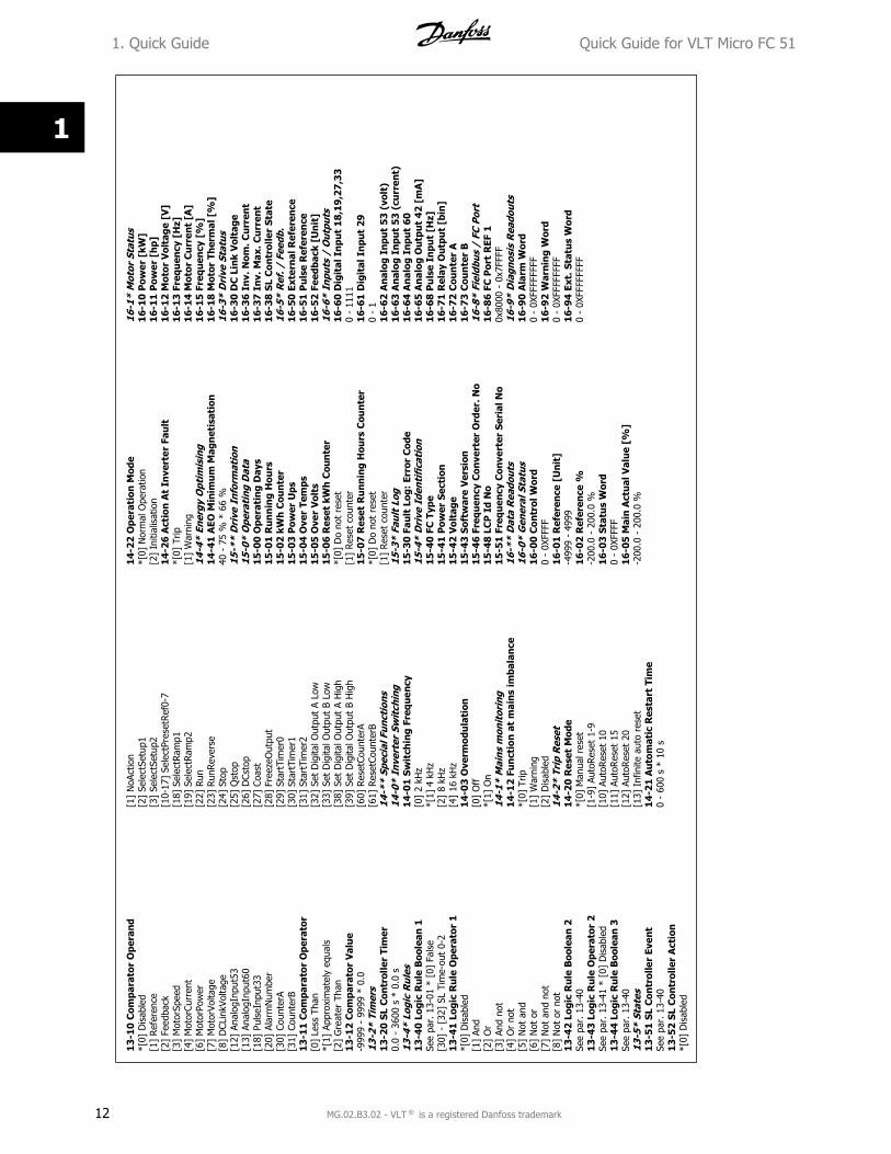
13
-10
Com
para
tor
Ope
ran
d*[
0] D
isab
led
[1]
Ref
eren
ce[2
] Fe
edba
ck[3
] M
otor
Spee
d[4
] M
otor
Curr
ent
[6]
Mot
orPo
wer
[7]
Mot
orVo
ltage
[8]
DCL
inkV
olta
ge[1
2] A
nalo
gInp
ut53
[13]
Ana
logI
nput
60[1
8] P
ulse
Inpu
t33
[20]
Ala
rmN
umbe
r[3
0] C
ount
erA
[31]
Cou
nter
B1
3-1
1 C
ompa
rato
r O
pera
tor
[0]
Less
Tha
n*[
1] A
ppro
xim
atel
y eq
uals
[2]
Gre
ater
Tha
n1
3-1
2 C
ompa
rato
r V
alu
e-9
999
- 99
99 *
0.0
13-2
* Ti
mer
s13
-20
SL C
ontr
olle
r Ti
mer
0.0
- 36
00 s
* 0
.0 s
13-4
* Lo
gic
Rul
es1
3-4
0 L
ogic
Ru
le B
oole
an 1
See
par.
13-
01 *
[0]
Fal
se[3
0] -
[32
] SL
Tim
e-ou
t 0-
21
3-4
1 L
ogic
Ru
le O
pera
tor
1*[
0] D
isab
led
[1]
And
[2]
Or
[3]
And
not
[4]
Or
not
[5]
Not
and
[6]
Not
or
[7]
Not
and
not
[8]
Not
or
not
13
-42
Log
ic R
ule
Boo
lean
2Se
e pa
r. 1
3-40
13
-43
Log
ic R
ule
Ope
rato
r 2
See
par.
13-
41 *
[0]
Dis
able
d1
3-4
4 L
ogic
Ru
le B
oole
an 3
See
par.
13-
4013
-5*
Stat
es13
-51
SL C
ontr
olle
r Ev
ent
See
par.
13-
401
3-5
2 S
L C
ontr
olle
r A
ctio
n*[
0] D
isab
led
[1]
NoA
ctio
n[2
] Se
lect
Setu
p1[3
] Se
lect
Setu
p2[1
0-17
] Se
lect
Pres
etRef
0-7
[18]
Sel
ectR
amp1
[19]
Sel
ectR
amp2
[22]
Run
[23]
Run
Rev
erse
[24]
Sto
p[2
5] Q
stop
[26]
DCs
top
[27]
Coa
st[2
8] F
reez
eOut
put
[29]
Sta
rtTi
mer
0[3
0] S
tart
Tim
er1
[31]
Sta
rtTi
mer
2[3
2] S
et D
igita
l Out
put
A Lo
w[3
3] S
et D
igita
l Out
put
B Lo
w[3
8] S
et D
igita
l Out
put
A H
igh
[39]
Set
Dig
ital O
utpu
t B
Hig
h[6
0] R
eset
Coun
terA
[61]
Res
etCo
unte
rB14
-**
Spec
ial F
unct
ions
14-0
* In
vert
er S
wit
chin
g14
-01
Swit
chin
g Fr
equ
ency
[0]
2 kH
z*[
1] 4
kH
z[2
] 8
kHz
[4]
16 k
Hz
14-0
3 O
verm
odu
lati
on[0
] O
ff*[
1] O
n14
-1*
Mai
ns m
onit
orin
g14
-12
Fun
ctio
n a
t m
ain
s im
bala
nce
*[0]
Trip
[1]
War
ning
[2]
Dis
able
d14
-2*
Trip
Res
et14
-20
Res
et M
ode
*[0]
Man
ual r
eset
[1-9
] Au
toRes
et 1
-9[1
0] A
utoR
eset
10
[11]
Aut
oRes
et 1
5[1
2] A
utoR
eset
20
[13]
Inf
inite
aut
o re
set
14-2
1 A
utom
atic
Res
tart
Tim
e0
- 60
0 s
* 10
s
14-2
2 O
pera
tion
Mod
e*[
0] N
orm
al O
pera
tion
[2]
Initi
alis
atio
n14
-26
Act
ion
At
Inve
rter
Fau
lt*[
0] T
rip[1
] W
arni
ng14
-4*
Ener
gy O
ptim
isin
g14
-41
AEO
Min
imu
m M
agn
etis
atio
n40
- 7
5 %
* 6
6 %
15-*
* D
rive
Inf
orm
atio
n15
-0*
Ope
rati
ng D
ata
15-0
0 O
pera
tin
g D
ays
15-0
1 R
un
nin
g H
ours
15-0
2 kW
h C
oun
ter
15-0
3 P
ower
Ups
15-0
4 O
ver
Tem
ps15
-05
Ove
r V
olts
15-0
6 R
eset
kW
h C
oun
ter
*[0]
Do
not
rese
t[1
] Res
et c
ount
er15
-07
Res
et R
un
nin
g H
ours
Cou
nte
r*[
0] D
o no
t re
set
[1]
Res
et c
ount
er15
-3*
Faul
t Lo
g15
-30
Fau
lt L
og:
Erro
r C
ode
15-4
* D
rive
Ide
ntif
icat
ion
15-4
0 FC
Typ
e15
-41
Pow
er S
ecti
on15
-42
Vol
tage
15-4
3 So
ftw
are
Ver
sion
15-4
6 Fr
equ
ency
Con
vert
er O
rder
. No
15-4
8 LC
P I
d N
o15
-51
Freq
uen
cy C
onve
rter
Ser
ial N
o16
-**
Dat
a R
eado
uts
16-0
* G
ener
al S
tatu
s1
6-0
0 C
ontr
ol W
ord
0 -
0XFF
FF16
-01
Ref
eren
ce [
Un
it]
-499
9 -
4999
16-0
2 R
efer
ence
%-2
00.0
- 2
00.0
%1
6-0
3 S
tatu
s W
ord
0 -
0XFF
FF16
-05
Mai
n A
ctu
al V
alu
e [%
]-2
00.0
- 2
00.0
%
16-1
* M
otor
Sta
tus
16-1
0 P
ower
[kW
]16
-11
Pow
er [
hp]
16-1
2 M
otor
Vol
tage
[V
]16
-13
Freq
uen
cy [
Hz]
16-1
4 M
otor
Cu
rren
t [A
]16
-15
Freq
uen
cy [
%]
16-1
8 M
otor
Th
erm
al [
%]
16-3
* D
rive
Sta
tus
16-3
0 D
C L
ink
Vol
tage
16-3
6 In
v. N
om. C
urr
ent
16-3
7 In
v. M
ax. C
urr
ent
16-3
8 SL
Con
trol
ler
Stat
e16
-5*
Ref
. / F
eedb
.16
-50
Exte
rnal
Ref
eren
ce16
-51
Pu
lse
Ref
eren
ce16
-52
Feed
back
[U
nit
]16
-6*
Inpu
ts /
Out
puts
16-6
0 D
igit
al I
npu
t 18
,19,
27,3
30
- 11
1116
-61
Dig
ital
Inp
ut
290
- 1
16-6
2 A
nal
og I
npu
t 53
(vo
lt)
16-6
3 A
nal
og I
npu
t 53
(cu
rren
t)16
-64
An
alog
Inp
ut
6016
-65
An
alog
Ou
tpu
t 4
2 [m
A]
16-6
8 P
uls
e In
put
[Hz]
16-7
1 R
elay
Ou
tpu
t [b
in]
16-7
2 C
oun
ter
A16
-73
Cou
nte
r B
16-8
* Fi
eldb
us /
FC
Port
16-8
6 FC
Por
t R
EF 1
0x80
00 -
0x7
FFFF
16-9
* D
iagn
osis
Rea
dout
s1
6-9
0 A
larm
Wor
d0
- 0X
FFFF
FFFF
16-9
2 W
arn
ing
Wor
d0
- 0X
FFFF
FFFF
16-9
4 Ex
t. S
tatu
s W
ord
0 -
0XFF
FFFF
FF
1. Quick Guide Quick Guide for VLT Micro FC 51
12 MG.02.B3.02 - VLT is a registered Danfoss trademark
1
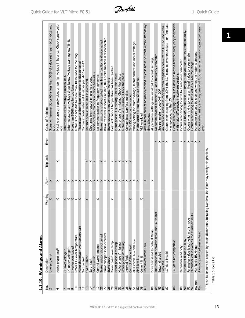
No.
Des
crip
tion
War
ning
Alar
mTr
ip L
ock
Erro
rCa
use
of P
robl
em2
Live
zer
o er
ror
XX
Sign
al o
n te
rmin
al 5
3 or
60
is le
ss t
han
50%
of
valu
e se
t in
par
. 6-
10, 6-
12 a
nd6-
22.
4M
ains
pha
se lo
ss1)
XX
X
Mis
sing
pha
se o
n su
pply
sid
e, o
r to
o hi
gh v
olta
ge im
bala
nce.
Che
ck s
uppl
y vo
lt-ag
e.7
DC
over
vol
tage
1)X
X
In
term
edia
te c
ircui
t vo
ltage
exc
eeds
lim
it.8
DC
unde
r vo
ltage
1)X
X
In
term
edia
te c
ircui
t vo
ltage
dro
ps b
elow
“vo
ltage
war
ning
low
” lim
it.9
Inve
rter
ove
rload
edX
X
M
ore
than
100
% lo
ad f
or t
oo lo
ng.
10M
otor
ETR
ove
r te
mpe
ratu
reX
X
M
otor
is t
oo h
ot d
ue t
o m
ore
than
100
% lo
ad f
or t
oo lo
ng.
11M
otor
the
rmis
tor
over
tem
pera
ture
XX
Ther
mis
tor
or t
herm
isto
r co
nnec
tion
is d
isco
nnec
ted.
12To
rque
lim
it
X
To
rque
exc
eeds
val
ue s
et in
eith
er p
ar. 4
-16
or 4
-17.
13O
ver
Curr
ent
XX
X
Inve
rter
pea
k cu
rren
t lim
it is
exc
eede
d.14
Eart
h fa
ult
X
X
Dis
char
ge f
rom
out
put
phas
es t
o gr
ound
.16
Shor
t Ci
rcui
t
XX
Sh
ort-
circ
uit
in m
otor
or
on m
otor
ter
min
als.
17Co
ntro
l wor
d tim
eout
XX
No
com
mun
icat
ion
to f
requ
ency
con
vert
er.
25Br
ake
resi
stor
sho
rt-c
ircui
ted
X
X
Brak
e re
sist
or is
sho
rt-c
ircui
ted,
thu
s br
ake
func
tion
is d
isco
nnec
ted.
27Br
ake
chop
per
shor
t-ci
rcui
ted
X
X
Brak
e tr
ansi
stor
is s
hort
-circ
uite
d, t
hus
brak
e fu
nctio
n is
dis
conn
ecte
d.28
Brak
e ch
eck
X
Brak
e re
sist
or is
not
con
nect
ed/w
orki
ng29
Pow
er b
oard
ove
r te
mp
XX
X
Hea
t-si
nk c
ut-o
ut t
empe
ratu
re h
as b
een
reac
hed.
30M
otor
pha
se U
mis
sing
X
X
Mot
or p
hase
U is
mis
sing
. Ch
eck
the
phas
e.31
Mot
or p
hase
V m
issi
ng
XX
M
otor
pha
se V
is m
issi
ng. C
heck
the
pha
se.
32M
otor
pha
se W
mis
sing
X
X
Mot
or p
hase
W is
mis
sing
. Che
ck t
he p
hase
.38
Inte
rnal
fau
lt
XX
Co
ntac
t lo
cal D
anfo
ss s
uppl
ier.
47Co
ntro
l Vol
tage
Fau
ltX
XX
24
V D
C m
ay b
e ov
erlo
aded
.51
AMT
chec
k U
nom a
nd I
nom
X
Wro
ng s
ettin
g fo
r m
otor
vol
tage
, mot
or c
urre
nt a
nd m
otor
vol
tage
.52
AMT
low
Ino
m
X
M
otor
cur
rent
is t
oo lo
w. Ch
eck
sett
ings
.59
Curr
ent
limit
X
VLT
over
load
.63
Mec
hani
cal B
rake
Low
X
Actu
al m
otor
cur
rent
has
not
exc
eede
d “r
elea
se b
rake
” cu
rren
t with
in “
star
t del
ay”
time
win
dow
.80
Driv
e In
itial
ised
to
Def
ault
Valu
e
X
Al
l par
amet
er s
ettin
gs a
re in
itial
ized
to
defa
ult
sett
ings
.84
The
conn
ectio
n be
twee
n dr
ive
and
LCP
is lo
st
XN
o co
mm
unic
atio
n be
twee
n LC
P an
d fr
eque
ncy
conv
erte
r85
Butt
on d
isab
led
X
See
para
met
er g
roup
0-4
* LC
P86
Copy
fai
l
XAn
err
or o
ccur
red
whi
le c
opyi
ng fro
m f
requ
ency
con
vert
er t
o LC
P or
vic
e ve
rsa.
87LC
P da
ta in
valid
X
Occ
urs
whe
n co
pyin
g fr
om L
CP if
the
LCP
con
tain
s er
rone
ous
data
- o
r if
no d
ata
was
upl
oade
d to
the
LCP
.88
LCP
data
not
com
patib
le
XO
ccur
s w
hen
copy
ing
from
LCP
if d
ata
are
mov
ed b
etw
een
freq
uenc
y co
nver
ters
with
maj
or d
iffer
ence
s in
sof
twar
e ve
rsio
ns.
89Pa
ram
eter
rea
d on
ly
XO
ccur
s w
hen
tryi
ng t
o w
rite
to a
rea
d-on
ly p
aram
eter
.90
Para
met
er d
atab
ase
busy
X
LCP
and
RS4
85 c
onne
ctio
n ar
e tr
ying
to
upda
te p
aram
eter
s si
mul
tane
ousl
y.91
Para
met
er v
alue
is n
ot v
alid
in t
his
mod
e
XO
ccur
s w
hen
tryi
ng t
o w
rite
an il
lega
l val
ue t
o a
para
met
er.
92Pa
ram
eter
val
ue e
xcee
ds t
he m
in/m
ax li
mits
X
Occ
urs
whe
n tr
ying
to
set
a va
lue
outs
ide
the
rang
e.nw
run
Not
Whi
le R
UN
ning
X
Para
met
er c
an o
nly
be c
hang
ed w
hen
the
mot
or is
sto
pped
.Er
r.A
wro
ng p
assw
ord
was
ent
ered
X
Occ
urs
whe
n us
ing
a w
rong
pas
swor
d fo
r ch
angi
ng a
pas
swor
d-pr
otec
ted
para
m-
eter
.1)
The
se f
aults
may
be
caus
ed b
y m
ains
dis
tort
ions
. Ins
talli
ng D
anfo
ss L
ine
Filte
r m
ay r
ectif
y th
is p
robl
em.
Tabl
e 1.
6: C
ode
list
1.1
.19
.W
arn
ings
an
d A
larm
s
Quick Guide for VLT Micro FC 51 1. Quick Guide
MG.02.B3.02 - VLT is a registered Danfoss trademark 13
1
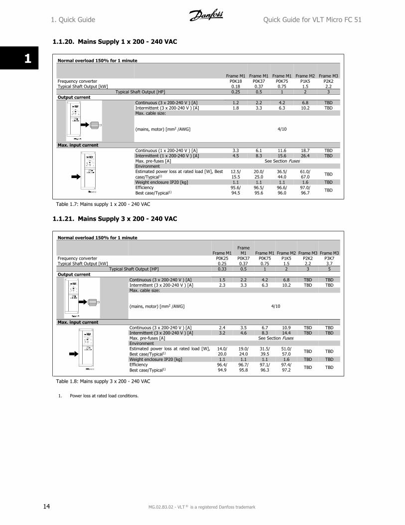
1.1.20. Mains Supply 1 x 200 - 240 VAC
Normal overload 150% for 1 minute
Frame M1 Frame M1 Frame M1 Frame M2 Frame M3Frequency converterTypical Shaft Output [kW]
P0K180.18
P0K370.37
P0K750.75
P1K51.5
P2K22.2
Typical Shaft Output [HP] 0.25 0.5 1 2 3Output current
Continuous (3 x 200-240 V ) [A] 1.2 2.2 4.2 6.8 TBDIntermittent (3 x 200-240 V ) [A] 1.8 3.3 6.3 10.2 TBDMax. cable size:
(mains, motor) [mm2 /AWG] 4/10
Max. input currentContinuous (1 x 200-240 V ) [A] 3.3 6.1 11.6 18.7 TBDIntermittent (1 x 200-240 V ) [A] 4.5 8.3 15.6 26.4 TBDMax. pre-fuses [A] See Section FusesEnvironmentEstimated power loss at rated load [W], Bestcase/Typical1)
12.5/15.5
20.0/25.0
36.5/44.0
61.0/67.0 TBD
Weight enclosure IP20 [kg] 1.1 1.1 1.1 1.6 TBDEfficiencyBest case/Typical1)
95.6/94.5
96.5/95.6
96.6/96.0
97.0/96.7 TBD
Table 1.7: Mains supply 1 x 200 - 240 VAC
1.1.21. Mains Supply 3 x 200 - 240 VAC
Normal overload 150% for 1 minute
Frame M1Frame
M1 Frame M1 Frame M2 Frame M3 Frame M3Frequency converterTypical Shaft Output [kW]
P0K250.25
P0K370.37
P0K750.75
P1K51.5
P2K22.2
P3K73.7
Typical Shaft Output [HP] 0.33 0.5 1 2 3 5Output current
Continuous (3 x 200-240 V ) [A] 1.5 2.2 4.2 6.8 TBD TBDIntermittent (3 x 200-240 V ) [A] 2.3 3.3 6.3 10.2 TBD TBDMax. cable size:
(mains, motor) [mm2 /AWG] 4/10
Max. input current Continuous (3 x 200-240 V ) [A] 2.4 3.5 6.7 10.9 TBD TBDIntermittent (3 x 200-240 V ) [A] 3.2 4.6 8.3 14.4 TBD TBDMax. pre-fuses [A] See Section FusesEnvironment Estimated power loss at rated load [W],Best case/Typical1)
14.0/20.0
19.0/24.0
31.5/39.5
51.0/57.0 TBD TBD
Weight enclosure IP20 [kg] 1.1 1.1 1.1 1.6 TBD TBDEfficiencyBest case/Typical1)
96.4/94.9
96.7/95.8
97.1/96.3
97.4/97.2 TBD TBD
Table 1.8: Mains supply 3 x 200 - 240 VAC
1. Power loss at rated load conditions.
1. Quick Guide Quick Guide for VLT Micro FC 51
14 MG.02.B3.02 - VLT is a registered Danfoss trademark
1
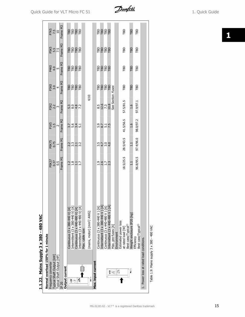
Nor
mal
ove
rloa
d 1
50
% f
or 1
min
ute
Freq
uenc
y co
nver
ter
Typi
cal S
haft
Out
put
[kW
]P0
K37
0.37
P0K7
50.
75P1
K51.
5P2
K22.
2P3
K03.
0P4
K04.
0P5
K55.
5P7
K57.
5Ty
pica
l Sha
ft O
utpu
t [H
P]0.
51
23
45
7.5
10IP
20
Fr
ame
M1
Fram
e M
1Fr
ame
M2
Fram
e M
2Fr
ame
M3
Fram
e M
3Fr
ame
M3
Fram
e M
3O
utp
ut
curr
ent
Cont
inuo
us (
3 x
380-
440
V) [
A]1.
22.
23.
75.
3TB
DTB
DTB
DTB
DIn
term
itten
t (3
x 3
80-4
40 V
) [A
]1.
83.
35.
68.
0TB
DTB
DTB
DTB
DCo
ntin
uous
(3
x 44
0-48
0 V)
[A]
1.1
2.1
3.4
4.8
TBD
TBD
TBD
TBD
Inte
rmitt
ent
(3 x
440
-480
V)
[A]
1.7
3.2
5.1
7.2
TBD
TBD
TBD
TBD
Max
. cab
le s
ize:
(mai
ns, m
otor
) [m
m2 /
AW
G]
4/10
Max
. in
put
curr
ent
Cont
inuo
us (
3 x
380-
440
V )
[A]
1.9
3.5
5.9
8.5
TBD
TBD
TBD
TBD
Inte
rmitt
ent
(3 x
380
-440
V )
[A]
2.6
4.7
8.7
12.6
TBD
TBD
TBD
TBD
Cont
inuo
us (
3 x
440-
480
V )
[A]
1.7
3.0
5.1
7.3
TBD
TBD
TBD
TBD
Inte
rmitt
ent
(3 x
440
-480
V )
[A]
2.3
4.0
7.5
10.8
TBD
TBD
TBD
TBD
Max
. pr
e-fu
ses
[A]
See
Sect
ion
Fuse
sEn
viro
nmen
tEs
timat
ed p
ower
loss
at r
ated
load
[W
]Be
st c
ase/
Typi
cal1)
18.5
/25.
528
.5/4
3.5
41.5
/56.
557
.5/8
1.5
TBD
TBD
TBD
TBD
Wei
ght
encl
osur
e IP
20 [
kg]
1.1
1.1
1.6
1.6
TBD
TBD
TBD
TBD
Effic
ienc
yBe
st c
ase/
Typi
cal1)
96.8
/95.
597
.4/9
6.0
98.0
/97.
297
.9/9
7.1
TBD
TBD
TBD
TBD
1.Po
wer
loss
at
rate
d lo
ad c
ondi
tions
.
Tabl
e 1.
9: M
ains
sup
ply
3 x
380
- 48
0 VA
C
1.1
.22
.M
ain
s Su
pply
3 x
38
0 -
48
0 V
AC
Quick Guide for VLT Micro FC 51 1. Quick Guide
MG.02.B3.02 - VLT is a registered Danfoss trademark 15
1
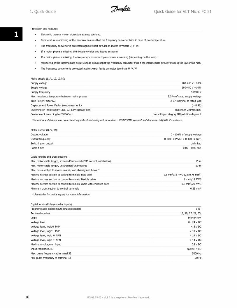
Protection and Features:
• Electronic thermal motor protection against overload.
• Temperature monitoring of the heatsink ensures that the frequency converter trips in case of overtemperature
• The frequency converter is protected against short-circuits on motor terminals U, V, W.
• If a motor phase is missing, the frequency trips and issues an alarm.
• If a mains phase is missing, the frequency converter trips or issues a warning (depending on the load).
• Monitoring of the intermediate circuit voltage ensures that the frequency converter trips if the intermediate circuit voltage is too low or too high.
• The frequency converter is protected against earth faults on motor terminals U, V, W.
Mains supply (L1/L, L2, L3/N):
Supply voltage 200-240 V ±10%
Supply voltage 380-480 V ±10%
Supply frequency 50/60 Hz
Max. imbalance temporary between mains phases 3.0 % of rated supply voltage
True Power Factor (�) � 0.4 nominal at rated load
Displacement Power Factor (cos�) near unity (> 0.98)
Switching on input supply L1/L, L2, L3/N (power-ups) maximum 2 times/min.
Environment according to EN60664-1 overvoltage category III/pollution degree 2
The unit is suitable for use on a circuit capable of delivering not more than 100.000 RMS symmetrical Amperes, 240/480 V maximum.
Motor output (U, V, W):
Output voltage 0 - 100% of supply voltage
Output frequency 0-200 Hz (VVC+), 0-400 Hz (u/f)
Switching on output Unlimited
Ramp times 0.05 - 3600 sec.
Cable lengths and cross sections:
Max. motor cable length, screened/armoured (EMC correct installation) 15 m
Max. motor cable length, unscreened/unarmoured 50 m
Max. cross section to motor, mains, load sharing and brake *
Maximum cross section to control terminals, rigid wire 1.5 mm2/16 AWG (2 x 0.75 mm2)
Maximum cross section to control terminals, flexible cable 1 mm2/18 AWG
Maximum cross section to control terminals, cable with enclosed core 0.5 mm2/20 AWG
Minimum cross section to control terminals 0.25 mm2
* See tables for mains supply for more information!
Digital inputs (Pulse/enocder inputs):
Programmable digital inputs (Pulse/encoder) 5 (1)
Terminal number 18, 19, 27, 29, 33,
Logic PNP or NPN
Voltage level 0 - 24 V DC
Voltage level, logic'0' PNP < 5 V DC
Voltage level, logic'1' PNP > 10 V DC
Voltage level, logic '0' NPN > 19 V DC
Voltage level, logic '1' NPN < 14 V DC
Maximum voltage on input 28 V DC
Input resistance, Ri approx. 4 k�
Max. pulse frequency at terminal 33 5000 Hz
Min. pulse frequency at terminal 33 20 Hz
1. Quick Guide Quick Guide for VLT Micro FC 51
16 MG.02.B3.02 - VLT is a registered Danfoss trademark
1
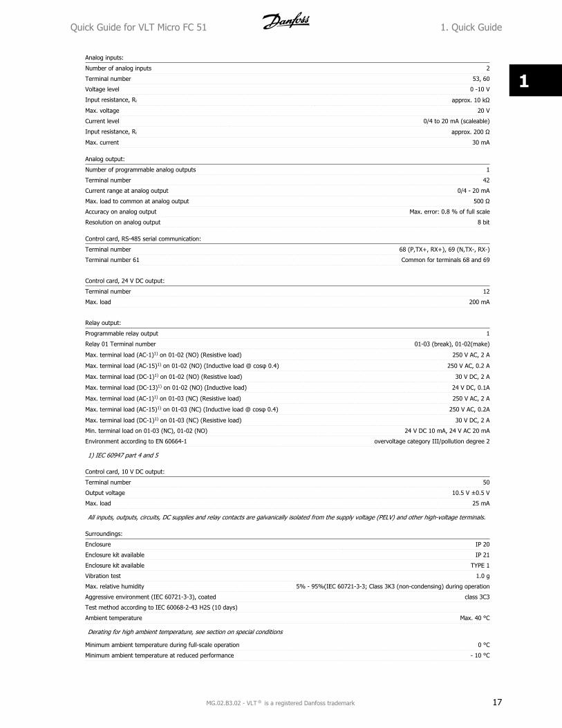
Analog inputs:
Number of analog inputs 2
Terminal number 53, 60
Voltage level 0 -10 V
Input resistance, Ri approx. 10 k�
Max. voltage 20 V
Current level 0/4 to 20 mA (scaleable)
Input resistance, Ri approx. 200 �
Max. current 30 mA
Analog output:
Number of programmable analog outputs 1
Terminal number 42
Current range at analog output 0/4 - 20 mA
Max. load to common at analog output 500 �
Accuracy on analog output Max. error: 0.8 % of full scale
Resolution on analog output 8 bit
Control card, RS-485 serial communication:
Terminal number 68 (P,TX+, RX+), 69 (N,TX-, RX-)
Terminal number 61 Common for terminals 68 and 69
Control card, 24 V DC output:
Terminal number 12
Max. load 200 mA
Relay output:
Programmable relay output 1
Relay 01 Terminal number 01-03 (break), 01-02(make)
Max. terminal load (AC-1)1) on 01-02 (NO) (Resistive load) 250 V AC, 2 A
Max. terminal load (AC-15)1) on 01-02 (NO) (Inductive load @ cos� 0.4) 250 V AC, 0.2 A
Max. terminal load (DC-1)1) on 01-02 (NO) (Resistive load) 30 V DC, 2 A
Max. terminal load (DC-13)1) on 01-02 (NO) (Inductive load) 24 V DC, 0.1A
Max. terminal load (AC-1)1) on 01-03 (NC) (Resistive load) 250 V AC, 2 A
Max. terminal load (AC-15)1) on 01-03 (NC) (Inductive load @ cos� 0.4) 250 V AC, 0.2A
Max. terminal load (DC-1)1) on 01-03 (NC) (Resistive load) 30 V DC, 2 A
Min. terminal load on 01-03 (NC), 01-02 (NO) 24 V DC 10 mA, 24 V AC 20 mA
Environment according to EN 60664-1 overvoltage category III/pollution degree 2
1) IEC 60947 part 4 and 5
Control card, 10 V DC output:
Terminal number 50
Output voltage 10.5 V ±0.5 V
Max. load 25 mA
All inputs, outputs, circuits, DC supplies and relay contacts are galvanically isolated from the supply voltage (PELV) and other high-voltage terminals.
Surroundings:
Enclosure IP 20
Enclosure kit available IP 21
Enclosure kit available TYPE 1
Vibration test 1.0 g
Max. relative humidity 5% - 95%(IEC 60721-3-3; Class 3K3 (non-condensing) during operation
Aggressive environment (IEC 60721-3-3), coated class 3C3
Test method according to IEC 60068-2-43 H2S (10 days)
Ambient temperature Max. 40 °C
Derating for high ambient temperature, see section on special conditions
Minimum ambient temperature during full-scale operation 0 °C
Minimum ambient temperature at reduced performance - 10 °C
Quick Guide for VLT Micro FC 51 1. Quick Guide
MG.02.B3.02 - VLT is a registered Danfoss trademark 17
1
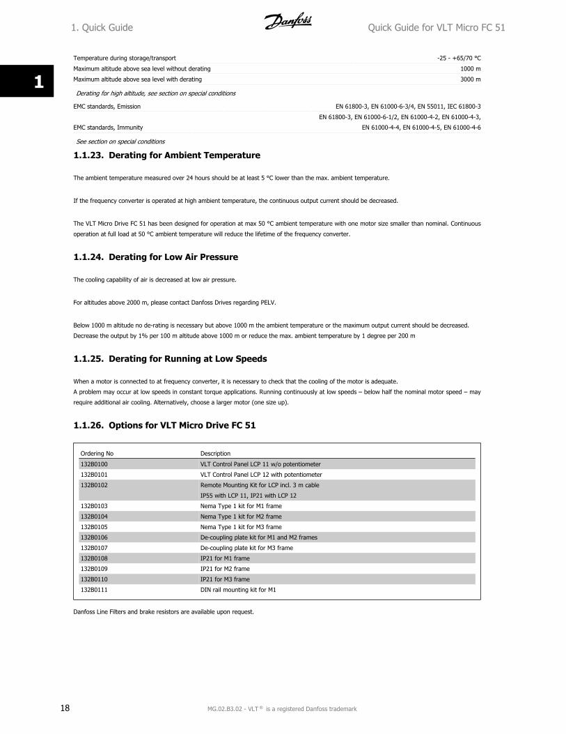
Temperature during storage/transport -25 - +65/70 °C
Maximum altitude above sea level without derating 1000 m
Maximum altitude above sea level with derating 3000 m
Derating for high altitude, see section on special conditions
EMC standards, Emission EN 61800-3, EN 61000-6-3/4, EN 55011, IEC 61800-3
EMC standards, Immunity
EN 61800-3, EN 61000-6-1/2, EN 61000-4-2, EN 61000-4-3,
EN 61000-4-4, EN 61000-4-5, EN 61000-4-6
See section on special conditions
1.1.23. Derating for Ambient Temperature
The ambient temperature measured over 24 hours should be at least 5 °C lower than the max. ambient temperature.
If the frequency converter is operated at high ambient temperature, the continuous output current should be decreased.
The VLT Micro Drive FC 51 has been designed for operation at max 50 °C ambient temperature with one motor size smaller than nominal. Continuous
operation at full load at 50 °C ambient temperature will reduce the lifetime of the frequency converter.
1.1.24. Derating for Low Air Pressure
The cooling capability of air is decreased at low air pressure.
For altitudes above 2000 m, please contact Danfoss Drives regarding PELV.
Below 1000 m altitude no de-rating is necessary but above 1000 m the ambient temperature or the maximum output current should be decreased.
Decrease the output by 1% per 100 m altitude above 1000 m or reduce the max. ambient temperature by 1 degree per 200 m
1.1.25. Derating for Running at Low Speeds
When a motor is connected to at frequency converter, it is necessary to check that the cooling of the motor is adequate.
A problem may occur at low speeds in constant torque applications. Running continuously at low speeds – below half the nominal motor speed – may
require additional air cooling. Alternatively, choose a larger motor (one size up).
1.1.26. Options for VLT Micro Drive FC 51
Ordering No Description
132B0100 VLT Control Panel LCP 11 w/o potentiometer
132B0101 VLT Control Panel LCP 12 with potentiometer
132B0102 Remote Mounting Kit for LCP incl. 3 m cable
IP55 with LCP 11, IP21 with LCP 12
132B0103 Nema Type 1 kit for M1 frame
132B0104 Nema Type 1 kit for M2 frame
132B0105 Nema Type 1 kit for M3 frame
132B0106 De-coupling plate kit for M1 and M2 frames
132B0107 De-coupling plate kit for M3 frame
132B0108 IP21 for M1 frame
132B0109 IP21 for M2 frame
132B0110 IP21 for M3 frame
132B0111 DIN rail mounting kit for M1
Danfoss Line Filters and brake resistors are available upon request.
1. Quick Guide Quick Guide for VLT Micro FC 51
18 MG.02.B3.02 - VLT is a registered Danfoss trademark
1


Rev. 2007-06-19
www.danfoss.com/drives
132R0029 MG02B302
*MG02B302*