quicksilver, and ride-guide. installation manual · pdf filebrunswick corporation: merc,...
TRANSCRIPT

90-861180990 SEPTEMBER 1999 Printed in U.S.A. - 1999, Mercury Marine Page 1 of 90
The following are registered trademarks ofBrunswick Corporation: Merc, MerCathode,MerCruiser, Mercury, Mercury Marine,Quicksilver, and Ride-Guide.
INSTALLATION MANUAL D7.3L D-TRONICDIESEL ENGINES - BRAVO MODELS
NOTICE to INSTALLER
After Completing Installation, These Instructions Should Be Placed with the Product for the Owner’sFuture Use.
NOTICE to COMMISSIONING DEALER
Predelivery Preparation Instructions Must be Performed Before Delivering Boat To The ProductOwner.
Table of Contents
General Information 2. . . . . . . . . . . . . . . . . . . . . . . Notice to Installer 2. . . . . . . . . . . . . . . . . . . . . . . . Bravo Three Notice: Trim-In Limit Pin 3. . . . . . Multiple Sterndrive Steering Tie Bar Arrangements 4. . . . . . . . . . . . . . . . . . . . . . . . . . . Quicksilver Products 5. . . . . . . . . . . . . . . . . . . . . Torque Specifications 6. . . . . . . . . . . . . . . . . . . . Serial Number Decal Placement 6. . . . . . . . . . . Corrosion Protection 6. . . . . . . . . . . . . . . . . . . . . Antifouling Paint 7. . . . . . . . . . . . . . . . . . . . . . . . .
Installation Requirements 8. . . . . . . . . . . . . . . . . Boat Construction 8. . . . . . . . . . . . . . . . . . . . . . . Exhaust System 11. . . . . . . . . . . . . . . . . . . . . . . . Fuel Delivery System 12. . . . . . . . . . . . . . . . . . . General 12. . . . . . . . . . . . . . . . . . . . . . . . . . . . . . . Battery 14. . . . . . . . . . . . . . . . . . . . . . . . . . . . . . . . Battery Cables 14. . . . . . . . . . . . . . . . . . . . . . . . . EDI Electrical System Precautions 15. . . . . . . . Instrumentation 15. . . . . . . . . . . . . . . . . . . . . . . . . Power Trim Control 16. . . . . . . . . . . . . . . . . . . . . Power Trim Pump Location 16. . . . . . . . . . . . . . Propeller Selection 17. . . . . . . . . . . . . . . . . . . . . . Hot Water Heater Installation Recommendation 18. . . . . . . . . . . . . . . . . . . . . . Seawater Connections 19. . . . . . . . . . . . . . . . . . Throttle/Shift Remote Control and Cables 20. . Steering Helm and Cable 21. . . . . . . . . . . . . . . .
Transom Cutout 23. . . . . . . . . . . . . . . . . . . . . . . . . . Finding Crankshaft Vertical Centerline 24. . . . . Finding Crankshaft Horizontal Centerline (“X” Dimension) 25. . . . . . . . . . . . . . . . . . . . . . . .
Cutting Transom 27. . . . . . . . . . . . . . . . . . . . . . . . .
Checking Transom Thickness 28. . . . . . . . . . . . . Installing Transom Assembly 29. . . . . . . . . . . . .
Gimbal Housing 29. . . . . . . . . . . . . . . . . . . . . . . . Inner Transom Plate 30. . . . . . . . . . . . . . . . . . . . Power Trim Pump 31. . . . . . . . . . . . . . . . . . . . . . Steering System 32. . . . . . . . . . . . . . . . . . . . . . . . Speedometer Pickup 35. . . . . . . . . . . . . . . . . . . . Drive Unit Gear Lube Monitor Hose 35. . . . . . . Exhaust Water Bypass 36. . . . . . . . . . . . . . . . . . Drive Unit Seawater Routing 37. . . . . . . . . . . . .
Engine Installation 39. . . . . . . . . . . . . . . . . . . . . . . Engine Preparation 39. . . . . . . . . . . . . . . . . . . . . Transom Preparation 40. . . . . . . . . . . . . . . . . . . . Installing Engine / Alignment 41. . . . . . . . . . . . .
Engine Connections 46. . . . . . . . . . . . . . . . . . . . . . Quicksilver Seawater Pickup and Seacock 46. Seawater Strainer 47. . . . . . . . . . . . . . . . . . . . . . Closed Cooling Recovery Bottle 48. . . . . . . . . . Fuel Lines 49. . . . . . . . . . . . . . . . . . . . . . . . . . . . . Power Steering Hydraulic Hoses 49. . . . . . . . . . Exhaust System 50. . . . . . . . . . . . . . . . . . . . . . . . Electrical Connections 50. . . . . . . . . . . . . . . . . . .
Shift Cable Installation and Adjustment 54. . . . Troubleshooting Shift Problems 58. . . . . . . . . . .
Throttle Cable Installation and Adjustment 60. Sterndrive Unit Installation 62. . . . . . . . . . . . . . . Predelivery Preparation 69. . . . . . . . . . . . . . . . . . . Power Trim System Wiring Diagram 84. . . . . . . MerCathode System Wiring Diagram 85. . . . . . Quicksilver Instrumentation Wiring 86. . . . . . . . Cooling System Flow Diagram 88. . . . . . . . . . . . Predelivery Inspection 90. . . . . . . . . . . . . . . . . . . .
D7.3L D-TRONIC DIESEL ENGINES - BRAVO MODELS
Page 2 of 90
General Information
Notice to InstallerThroughout this publication, “Warnings” and “Cautions” (accompanied by the InternationalHazard Symbol ! ) are used to alert the installer to special instructions concerning a partic-ular service or operation that may be hazardous if performed incorrectly or carelessly. ––Observe Them Carefully!
These “Safety Alerts,” alone, cannot eliminate the hazards that they signal. Strict com-pliance to these special instructions when performing the service, plus “common sense” op-eration, are major accident prevention measures.
WARNINGHazards or unsafe practices which could result in severe personal injury or death.
CAUTIONHazards or unsafe practices which could result in minor personal injury or productor property damage.
IMPORTANT: Indicates information or instructions that are necessary for proper in-stallation and/or operation.
This installation manual, including all installation requirements, has been written and pub-lished by Mercury Marine to aid boat manufacturers and installers involved in the applicationand installation of the products described herein.
It is assumed that these personnel are familiar with the installation procedures of these prod-ucts, or like or similar products manufactured and marketed by Mercury Marine. That theyhave been trained in the recommended installation procedures of these products which in-cludes the use of mechanics’ common hand tools and the special Mercury Marine or recom-mended tools from other suppliers.
It is the responsibility of the OEM to select the appropriate engine/transom/drive package(including the correct gear ratio and propeller) for a given boat. Making an appropriate selec-tion requires knowledge of the boat (weight, length, hull design, intended use and duty cycle,desired speed, etc.) that is uniquely in the possession of the OEM. While Mercury employspeople capable of assisting the OEM on such issues, the final decision rests with the OEM.Mercury recommends that any new or unique hull/power package combination be thor-oughly water tested prior to sale, to verify (among other things) that the boat performs asdesired, and that the engine runs in the appropriate rpm range.
We could not possibly know of and advise the marine trade of all conceivable proceduresby which an installation might be performed, and of the possible hazards and/or results ofeach method. We have not undertaken any such wide evaluation. Therefore, anyone whouses an installation procedure and/or tool, which is not recommended by the manufacturer,first must completely satisfy himself that neither his nor the product’s safety will be endan-gered by the installation procedure selected.
It is recommended that a Mercury Marine Field Product Engineer be contacted for assis-tance if specific application or installation problems are encountered.
All information, illustrations, and specifications contained in this manual are based on thelatest product information available at time of publication. As required, revisions to this man-ual will be sent to all OEM boat companies.

D7.3L D-TRONIC DIESEL ENGINES - BRAVO MODELS
Page 3 of 90
WARNINGElectrical system components on this engine are not external ignition protected.DO NOT STORE OR UTILIZE GASOLINE ON BOATS EQUIPPED WITH THESE EN-GINES, UNLESS PROVISIONS HAVE BEEN MADE TO EXCLUDE GASOLINE VA-PORS FROM ENGINE COMPARTMENT (REF: 33 CFR). Failure to comply could re-sult in fire, explosion and/or severe personal injury.
Notice on Bravo Trim-In LimitNOTE: Bravo One, Two and Three Models are equipped with a Trim-In Limit Pin Insert.
It has been brought to our attention that some boats (predominantly deep-V heavy boats)will roll up on their side under certain, specific, operating conditions. The roll can be eitherto port or starboard and may be experienced while moving straight ahead, or while makinga turn. The roll occurs most frequently at or near maximum speed, with the drive unittrimmed at or near full trim-in. While the boat will not roll completely over, the roll may besufficient to unseat the operator or passengers, and thereby create an unsafe situation.
The roll is caused by stern-lift created from excessive drive unit trim-in. Under these extremestern-lift / bow-down conditions instability can be created which may cause the boat to roll.Weight distribution to the stern can reduce stern-lift and, in some circumstances, help tocontrol the condition. Weight distribution in the bow, port or starboard, may worsen thecondition.
The Trim-In Limit Pin Insert reduces stern-lift by preventing the drive unit from reaching thelast few degrees of full trim-in. While this device should reduce the rolling tendency, it maynot eliminate the tendency entirely. The need for this Trim-In Limit Pin Insert, and its effec-tiveness, can only be determined through boat testing and is ultimately the responsibility ofthe boat manufacturer.
WARNINGIt is recommended that only qualified personnel adjust the Trim-In Limit Pin Insert.Boat must be water tested after adjusting or removing the device to ensure that themodified trim-in range does not cause the boat to exhibit an undesirable boat handl-ing characteristic if the drive unit is trimmed In at higher speeds. Increased trim-inrange may cause handling problems on some boats which could result in personalinjury.

D7.3L D-TRONIC DIESEL ENGINES - BRAVO MODELS
Page 4 of 90
Multiple Sterndrive Steering Tie Bar ArrangementsWith multiple sterndrives it is important to consider which of several possible steering sys-tems should be selected.
CAUTIONFailure to observe the recommended Tie Bar Arrangements as presented in thissection could result in serious damage to the steering and/or trim system compo-nents. This damage could adversely affect control of the boat.
INTERNAL TIE BAR ONLY
At the lower end of the performance spectrum (boats not capable of speeds in excess of60 MPH) the basic internal tie bar is recommended. It connects the slave sterndrive to thesterndrive that is directly connected to the factory power steering output. This internal tiebar is available in a variety of lengths from the sterndrive manufacturer.
INTERNAL AND EXTERNAL TIE BAR
As a boat moves into a moderate performance range (60-70 MPH) or for a reduction in steer-ing backlash, an external tie bar should be added. External tie bars are usually designedto attach at the aft power trim cylinder bosses which is an excellent location because of itsproximity to the propeller. HOWEVER, because of the potential overstress that can occurif one drive is trimmed much differently than the other, a dual trim control kit (Part Number90362A3) should be installed so as to limit this potential tilt differential to about 20°.
EXTERNAL POWER STEERING
When boat speeds move past 70 MPH or if additional steering backlash reduction is desired,external power steering is recommended. This normally will include an external tie barmounted at the same general location of the power steering cylinders which are generallyattached at the top of the sterndrive’s drive shaft housing. With this steering system, no inter-nal tie bar should be used. These steering cylinders can be attached either inboard (be-tween) or outboard of the sterndrives.
EXTERNAL POWER STEERING WITH LOW EXTERNAL TIE BAR
For the fastest boats (over 80 MPH) or for the ultimate in steering backlash reduction, useexternal power steering, BUT (where mechanically possible) with the external tie barmounted at the trim cylinder boss location (as previously described in “Internal and ExternalTie Bar” statements). Again this system does not use an internal tie bar.
Mercury Marine does not recommend the use of an external tie bar ONLY (no internal tiebar) when using the internal power steering system. This can cause excessive loads on thesteering components on the drive connected to the internal power steering system. Theseincreased loads can damage the steering components, resulting in increased play in thesteering of the boat.

D7.3L D-TRONIC DIESEL ENGINES - BRAVO MODELS
Page 5 of 90
Quicksilver Products
ACCESSORIES
Quicksilver remote controls, steering systems, propellers, etc. are available for this product.Refer to “Quicksilver Accessories Guide” for complete listing.
This “Guide” is available from:
Attn: Parts DepartmentMercury MarineW6250 W. Pioneer RoadP.O. Box 1939Fond du Lac, WI 54936-1939
OR –
Outside of U.S.A., order throughDistribution Center, or Distributor.
INSTALLATION PRODUCTS
DESCRIPTION PART NUMBER
Quicksilver Engine Coupler Spline Grease 92-816391A4
Quicksilver 2-4-C Marine Lubricant With Teflon 92-825407A3
Quicksilver U-Joint and Gimbal Bearing Grease 92-828052A3
Quicksilver Special Lubricant 101 92-13872A1
Quicksilver Liquid Neoprene 92-25711-2
Quicksilver Perfect Seal 92-34227-1
Transom Drilling Fixture 91-43693A2
Engine Alignment Tool 91-805475A1
Shift Cable Adjustment Tool 91-12427
Engine Lifting Eye Tool 91-806451A1
Engine Mount Drilling Fixture 91-807903A1
D7.3L D-TRONIC DIESEL ENGINES - BRAVO MODELS
Page 6 of 90
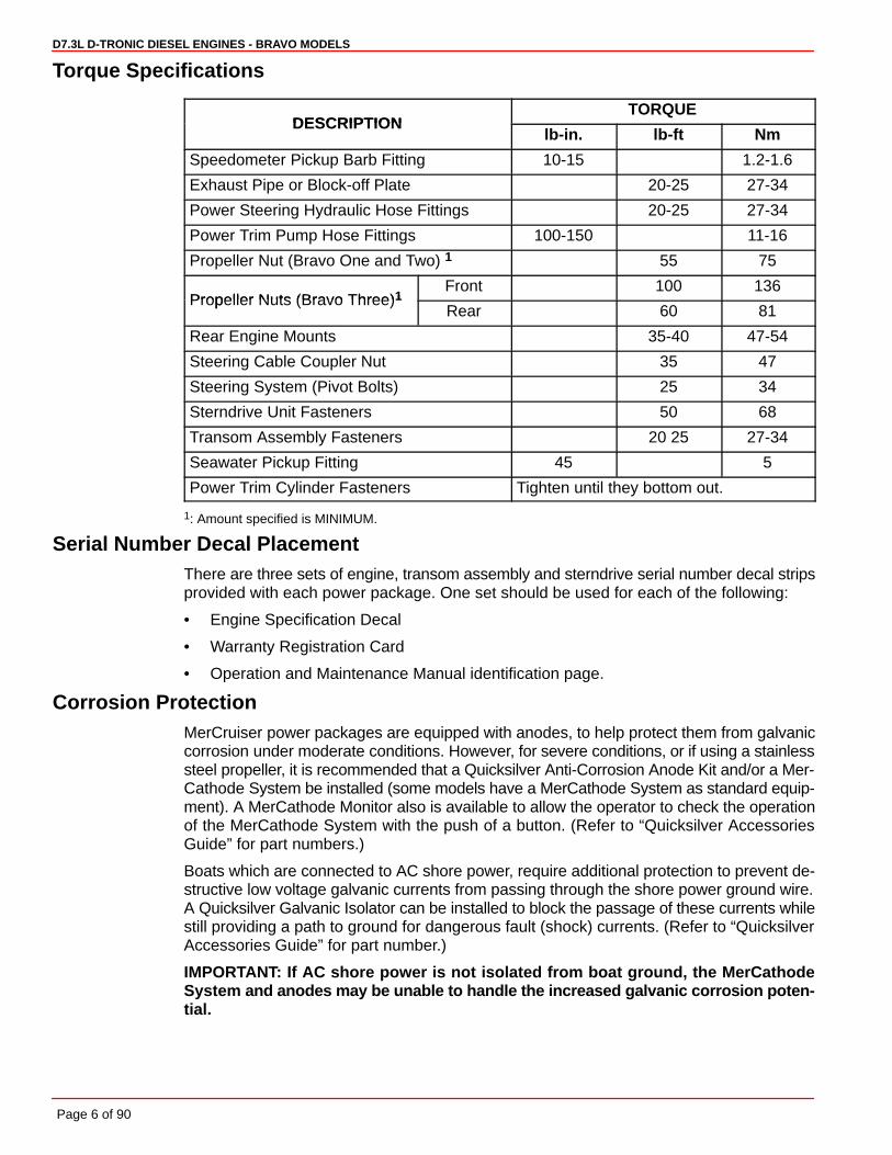
Torque Specifications
DESCRIPTIONTORQUE
DESCRIPTIONlb-in. lb-ft Nm
Speedometer Pickup Barb Fitting 10-15 1.2-1.6
Exhaust Pipe or Block-off Plate 20-25 27-34
Power Steering Hydraulic Hose Fittings 20-25 27-34
Power Trim Pump Hose Fittings 100-150 11-16
Propeller Nut (Bravo One and Two) 1 55 75
Propeller Nuts (Bravo Three)1Front 100 136
Propeller Nuts (Bravo Three)1Rear 60 81
Rear Engine Mounts 35-40 47-54
Steering Cable Coupler Nut 35 47
Steering System (Pivot Bolts) 25 34
Sterndrive Unit Fasteners 50 68
Transom Assembly Fasteners 20 25 27-34
Seawater Pickup Fitting 45 5
Power Trim Cylinder Fasteners Tighten until they bottom out.
1: Amount specified is MINIMUM.
Serial Number Decal PlacementThere are three sets of engine, transom assembly and sterndrive serial number decal stripsprovided with each power package. One set should be used for each of the following:
• Engine Specification Decal
• Warranty Registration Card
• Operation and Maintenance Manual identification page.
Corrosion ProtectionMerCruiser power packages are equipped with anodes, to help protect them from galvaniccorrosion under moderate conditions. However, for severe conditions, or if using a stainlesssteel propeller, it is recommended that a Quicksilver Anti-Corrosion Anode Kit and/or a Mer-Cathode System be installed (some models have a MerCathode System as standard equip-ment). A MerCathode Monitor also is available to allow the operator to check the operationof the MerCathode System with the push of a button. (Refer to “Quicksilver AccessoriesGuide” for part numbers.)
Boats which are connected to AC shore power, require additional protection to prevent de-structive low voltage galvanic currents from passing through the shore power ground wire.A Quicksilver Galvanic Isolator can be installed to block the passage of these currents whilestill providing a path to ground for dangerous fault (shock) currents. (Refer to “QuicksilverAccessories Guide” for part number.)
IMPORTANT: If AC shore power is not isolated from boat ground, the MerCathodeSystem and anodes may be unable to handle the increased galvanic corrosion poten-tial.

D7.3L D-TRONIC DIESEL ENGINES - BRAVO MODELS
Page 7 of 90
Antifouling PaintIMPORTANT: Corrosion damage that results from the improper application of anti-fouling paint will not be covered by the limited warranty.
Painting Boat Hull or Boat T ransom: Antifouling paint may be applied to boat hull and boattransom but you must observe the following precautions:
IMPORTANT: DO NOT paint anodes or MerCathode System reference electrode andanode, as this will render them ineffective as galvanic corrosion inhibitors.
IMPORTANT: If anti-fouling protection is required for boat hull or boat transom , cop-per or tin base paints, if not prohibited by law, can be used. If using copper or tinbased anti-fouling paints, observe the following:
• Avoid an electrical interconnection between the MerCruiser Product, AnodicBlocks, or MerCathode System and the paint by allowing a minimum of 1-1/2 in.(40mm) UNPAINTED area on transom of the boat around these items.
71176
a
b
a - Painted Boat Transomb - Minimum 1-1/2 in. (40 mm) UNPAINTED Area Around Transom Assembly
NOTE: Drive unit and transom assembly can be painted with a good quality marine paintor an anti-fouling paint that DOES NOT contain copper, tin, or any other material that couldconduct electrical current. Do not paint drain holes, anodes, MerCathode system, and itemsspecified by boat manufacturer.

D7.3L D-TRONIC DIESEL ENGINES - BRAVO MODELS
Page 8 of 90
Installation Requirements
Boat Construction
TRANSOM
22170
22033b
c
fa
d
e e
a - Transom Thickness - 2 in. (51mm) Minimum to 2-1/4 in.(57mm) Maximumb - Inner Surface of Transom Must Be Parallel Within 1/8 in. (3mm) in Area
Covered by Transom Plate (e) and Remain Within Transom Thickness Limits.c - Outer Surface of Transom Must Be Parallel Within 1/16 in. (2 mm) in Area
Covered by Transom Plate (e) and Remain Within Transom Thickness Limits.d - Remove Keel (if Equipped) 4 ft. (1.2m) Forward to Transome - Transom Plate Covers 8 in. (203 mm) to either side of the vertical centerlinef - Transom Angle - 10 Degrees to 16 Degrees
ENGINE BED
Distance between starboard and port engine mount is 22-1/2 in. (572mm). Engine bed mustposition engine so that a minimum of 1/4 in. (6mm) up and down adjustment still exists onmounts after performing final engine alignment. This is necessary to allow for realigning en-gine in the future.
NOTE: Although the engine mounts allow some adjustment, it is a good practice to insurethat the front and rear mount locations in the vessel are in parallel planes. This may bechecked by tying a string from the left front mount location to the right rear mount locationand another from right front to left rear. The strings should touch where they cross.
D7.3L D-TRONIC DIESEL ENGINES - BRAVO MODELS
Page 9 of 90
ENGINE COMPARTMENT
WARNINGBoating standards (NMMA, ABYC, etc.) and Coast Guard regulations must be ad-hered to when constructing the engine compartment.
Care must be exercised in the design and construction of the engine compartment. Seamsmust be located so that any rain water, which may leak through the seams, is directed awayfrom the air intake system. Water, that runs onto the air intake, may enter the engineand cause serious damage to internal engine and/or turbocharger parts.
IMPORTANT: MerCruiser will not honor any warranty claim for engine damage as aresult of water entry.
ENGINE COMPARTMENT VENTILATION
General Information
According to Boating standards (NMMA, ABYC, etc.) and Coast Guard regulations the en-gine compartment ventilation system has multiple tasks. Included are the following:
1. To supply the engine with combustion air.
2. To maintain a low temperature in the engine compartment.
Fresh air should enter the engine compartment as low as possible and the heated air shouldbe discharged from the highest point.
If a separate air shaft (or similar) is used to provide engine compartment ventilation, or addi-tional ventilation, care must be taken to prevent seawater and spray from entering it.
Combustion Air Requirements
Engine compartments with natural draft ventilation must have vent openings of sufficientsize and location to accomplish the tasks previously outlined.
Furthermore, in part, and according to, ABYC H-32-89 specification - “Compartment Ven-tilation (Diesel)” states:
“Ventilating provisions and openings to the machinery space provided for suppling combus-tion air shall accommodate the air requirements required by the engine manufacturer(s) foreach propulsion and auxiliary engine in that space. These openings may also function asmeans of providing natural ventilation.”
IMPORTANT: The size of ventilation openings must be increased if any auxiliaryequipment is located in the engine compartment.
The combustion air requirement (per engine) for the specified engines at Wide OpenThrottle are shown in the chart below:
Combustion Air Requirements (Per Engine)
Model Engine Air Requirements atWide Open Throttle
D7.3L D-Tronic and D7.3L D-Tronic LD 1000 ft.3/min. (28.2 m3/min.)
D7.3L D-TRONIC DIESEL ENGINES - BRAVO MODELS
Page 10 of 90
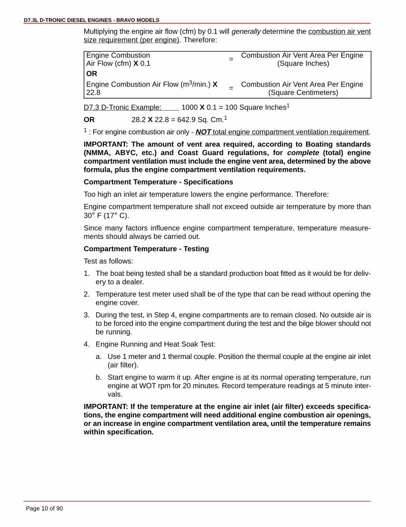
Multiplying the engine air flow (cfm) by 0.1 will generally determine the combustion air ventsize requirement (per engine). Therefore:
Engine CombustionAir Flow (cfm) X 0.1
= Combustion Air Vent Area Per Engine (Square Inches)
OREngine Combustion Air Flow (m3/min.) X22.8
= Combustion Air Vent Area Per Engine (Square Centimeters)
D7.3 D-Tronic Example: 1000 X 0.1 = 100 Square Inches1
OR 28.2 X 22.8 = 642.9 Sq. Cm.1
1 : For engine combustion air only - NOT total engine compartment ventilation requirement.
IMPORTANT: The amount of vent area required, according to Boating standards(NMMA, ABYC, etc.) and Coast Guard regulations, for complete (total) enginecompartment ventilation must include the engine vent area, determined by the aboveformula, plus the engine compartment ventilation requirements.
Compartment Temperature - Specifications
Too high an inlet air temperature lowers the engine performance. Therefore:
Engine compartment temperature shall not exceed outside air temperature by more than30° F (17° C).
Since many factors influence engine compartment temperature, temperature measure-ments should always be carried out.
Compartment Temperature - Testing
Test as follows:
1. The boat being tested shall be a standard production boat fitted as it would be for deliv-ery to a dealer.
2. Temperature test meter used shall be of the type that can be read without opening theengine cover.
3. During the test, in Step 4, engine compartments are to remain closed. No outside air isto be forced into the engine compartment during the test and the bilge blower should notbe running.
4. Engine Running and Heat Soak Test:
a. Use 1 meter and 1 thermal couple. Position the thermal couple at the engine air inlet(air filter).
b. Start engine to warm it up. After engine is at its normal operating temperature, runengine at WOT rpm for 20 minutes. Record temperature readings at 5 minute inter-vals.
IMPORTANT: If the temperature at the engine air inlet (air filter) exceeds specifica-tions, the engine compartment will need additional engine combustion air openings,or an increase in engine compartment ventilation area, until the temperature remainswithin specification.
D7.3L D-TRONIC DIESEL ENGINES - BRAVO MODELS
Page 11 of 90
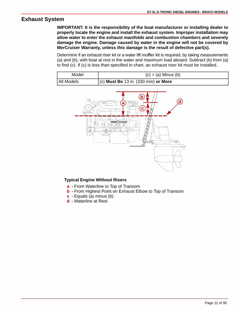
Exhaust SystemIMPORTANT: It is the responsibility of the boat manufacturer or installing dealer toproperly locate the engine and install the exhaust system. Improper installation mayallow water to enter the exhaust manifolds and combustion chambers and severelydamage the engine. Damage caused by water in the engine will not be covered byMerCruiser Warranty, unless this damage is the result of defective part(s).
Determine if an exhaust riser kit or a water lift muffler kit is required, by taking measurements(a) and (b), with boat at rest in the water and maximum load aboard. Subtract (b) from (a)to find (c). If (c) is less than specified in chart, an exhaust riser kit must be installed.
Model (c) = (a) Minus (b)
All Models (c) Must Be 13 in. (330 mm) or More
merCruiser
ab
cd
Typical Engine Without Risersa - From Waterline to Top of Transomb - From Highest Point on Exhaust Elbow to Top of Transomc - Equals (a) minus (b)d - Waterline at Rest
D7.3L D-TRONIC DIESEL ENGINES - BRAVO MODELS
Page 12 of 90
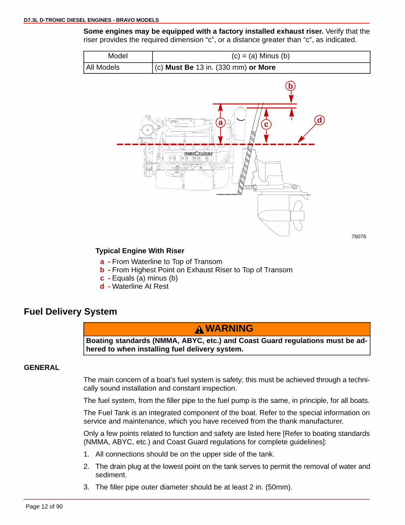
Some engines may be equipped with a factory installed exhaust riser. Verify that theriser provides the required dimension “c”, or a distance greater than “c”, as indicated.
Model (c) = (a) Minus (b)
All Models (c) Must Be 13 in. (330 mm) or More
merCruiser
a c d
b
76076
Typical Engine With Risera - From Waterline to Top of Transomb - From Highest Point on Exhaust Riser to Top of Transomc - Equals (a) minus (b)d - Waterline At Rest
Fuel Delivery System
WARNINGBoating standards (NMMA, ABYC, etc.) and Coast Guard regulations must be ad-hered to when installing fuel delivery system.
GENERAL
The main concern of a boat’s fuel system is safety; this must be achieved through a techni-cally sound installation and constant inspection.
The fuel system, from the filler pipe to the fuel pump is the same, in principle, for all boats.
The Fuel Tank is an integrated component of the boat. Refer to the special information onservice and maintenance, which you have received from the thank manufacturer.
Only a few points related to function and safety are listed here [Refer to boating standards(NMMA, ABYC, etc.) and Coast Guard regulations for complete guidelines]:
1. All connections should be on the upper side of the tank.
2. The drain plug at the lowest point on the tank serves to permit the removal of water andsediment.
3. The filler pipe outer diameter should be at least 2 in. (50mm).

D7.3L D-TRONIC DIESEL ENGINES - BRAVO MODELS
Page 13 of 90
4. The tank breather pipe must have an inner diameter of at least 1/2 in. (13mm) and mustbe fitted with a swan neck to prevent water from entering the tank.
It is recommended that the exact route and length of the fuel lines be established at the firstinstallation of the engine to prevent problems later in connecting them to the engine.
All fuel lines must be well secured. The holes where the lines run through the bulkheadsshould be carefully rounded off, or protected with rubber grommets. This prevents damageto the lines from abrasion.
FUEL CONNECTIONS
The following, but not limited to the following, additional fuel connection related points, ap-plying to all engines unless otherwise stated, must be considered [Refer to boating stan-dards (NMMA, ABYC, etc.) and Coast Guard regulations for complete guidelines]:
1. Fuel pickup should be at least 1 in. (25mm) from the bottom of fuel tank, to prevent pick-ing up impurities.
2. Fuel supply lines must not be smaller than 3/8 in. (11 mm) I.D. tube for V8 model. A fuelreturn line between engine and fuel tank is required, for all models the return line mustnot be smaller than 5/16 in. (8 mm).
3. On Multi-Engine Installations: Use a separate tube for the fuel supply line and fuelreturn line for each engine.
4. Larger diameter (than previously specified) lines, and fittings must be used on installa-tions requiring long lines or numerous fittings.
5. Fuel line(s) should be installed free of stress and firmly secured to prevent vibration and/or chafing.
6. Sharp bends in fuel lines should be avoided.
7. A flexible fuel line must be used to connect fuel supply line to fuel inlet fitting on engine,to absorb deflection when engine is running. Injection pump fuel return line must alsohave a flexible rubber hose segment.
DIESEL FUEL FILTERS AND FUEL ADDITIVES
There is the possibility that contamination of diesel fuel and algae growth in the diesel fuelcould cause the blockage of the lift pump resulting in poor performance.
IMPORTANT: The engine is provided with an element type fuel filter, but to help elimi-nate water and dirt it is recommended to use an additional 10 micron, 60 gal/min. (227L/min.) flow rated filter that has a water trap.
It is recommended that in MerCruiser Diesel applications, an additional fuel filter equippedwith a water trap be installed before the lift pump. MerCruiser recommends a 10 micron, 60gallon per minute (227 L/min.) rated filter, such as a Racor Model 500 (Quicksilver PartNumber 35-850481 with SAE threads, and 35-809867 with Metric threads) or equivalent.This will help to filter out contaminants in diesel fuel.
Select a suitable position in the fuel system between the fuel feed pump and the fuel tankfor the additional filter The position selected must be free from vibrations, and allow for easyinspection and replacement.
It is also recommended that a diesel fuel additive be added (to combat algae growth) particu-larly in warmer climates. Additives reduce the chances of algae growth in the diesel fuel.

D7.3L D-TRONIC DIESEL ENGINES - BRAVO MODELS
Page 14 of 90
BatteryIMPORTANT: Boating industry standards (BIA, ABYC, etc.) federal standards andCoast Guard regulations must be adhered to when installing battery. Be sure batterycable installation meets the pull test requirements and that positive battery terminalis properly insulated in accordance with regulations.
IMPORTANT: It is recommended (required in some states) that battery be installed inan enclosed case. Refer to regulations for your area.
IMPORTANT: Engine electrical system is negative (–) ground.
Select a battery that meets all of the following specifications:
• 12-volt marine type.
• Tapered post connectors or side terminal connectors. Do not use a battery with wing nutconnectors.
• Battery capacity rating of at least:
Engine(Cyl./type)
Minimum Required CrankingBattery Size
8 / V, D7.3L D-Tronic and D7.3L D-Tronic LD 1500 cca, 1920 mca or 300 Ah
Battery CablesSelect proper size positive (+) and negative (–) battery cables, using chart. Battery shouldbe located as close to engine as possible.
IMPORTANT: Terminals must be soldered to cable ends to ensure good electricalcontact. Use electrical grade (resin flux) solder only. Do not use acid flux solder, asit may cause corrosion and a subsequent failure.
Battery Cable Length Minimum CableGauge
Up to 3 ft. (0.9m) 2 ( 35mm2)
3 - 3-3/4 ft. (0.9 - 1.1m) 1 ( 50mm2)
3-3/4 - 4-3/4 ft. (1.1 - 1.4m) 0 ( 50mm2)
4-3/4 - 6 ft. (1.4 - 1.8m) 00 ( 70mm2)
6 - 7-1/2 ft. (1.8 - 2.3m) 000 ( 95mm2)
7-1/2 - 9-1/2 ft. (2.3 - 2.9m) 0000 (120mm2)
9-1/2 - 12 ft. (2.9 - 3.7m) � 00 ( 70mm2)
12 - 15 ft. (3.7 - 4.6m) � 000 ( 95mm2)
15 - 19 ft. (4.6 - 5.8m) � 0000 (120mm2)
� :Two cables of specified gauge required for positive and two required for negative.

D7.3L D-TRONIC DIESEL ENGINES - BRAVO MODELS
Page 15 of 90
EDI Electrical System PrecautionsNOTE: The following precautions apply to all EDI model Engines.
CAUTIONAvoid damage to the Electronic Direct Injection (EDI) electrical system and compo-nents. Refer to the following precautions when working on or around the EDI electri-cal harness or when adding other electrical accessories:
• DO NOT tap accessories into engine harness.
• DO NOT puncture wires for testing (Probing).
• DO NOT reverse battery leads.
• DO NOT splice wires into harness.
• DO NOT attempt diagnostics without proper, approved Service Tools.
Instrumentation
GENERAL
We recommend using Quicksilver Instrumentation and Wiring Harnesses. Refer to “Quick-silver Accessories Guide” for selection.
NOTE: If using other than Quicksilver instrumentation and harnesses, refer to manufactur-ers’ instructions.
The six basic gauges that must be used with the engine are:
• Tachometer
• Oil Pressure
• Water Temperature
• Voltmeter
• Cruise Log (Engine Hour Meter)
• Trim Gauge
When using the instrumentation, instrument harness wire connectors are labeled. It will benecessary to connect them onto the individual Quicksilver instruments, switches and En-gine System Monitor panel. The instrumentation harness ends are provided for connectioninto the appropriate extension harness ends. The wiring harnesses will then be ready toroute to the engine.
On dual station applications, oil pressure and water temperature senders (on engine) mustbe changed.
Additionally, changes are needed in the primary station key switch wiring to allow use of startand stop switches common on dual station panels. Refer to instructions in kit.
When routing any wiring extension harness back to the engine, make sure that the harnessdoes not rub or get pinched. Be sure all extension harness connector collars are secure.Fasten harnesses to boat at least every 18 in. (460 mm) using appropriate fasteners.

D7.3L D-TRONIC DIESEL ENGINES - BRAVO MODELS
Page 16 of 90
76010
a
c b
D7.3L D-Tronic Shown - All Similara - Engine Harness Connectorb - Extension Harness Connector (From Instruments)c - Electrical Bracket
TACHOMETER SPECIAL INFORMATION
IMPORTANT: If using a tachometer from another manufacturer, do not use the mag-netic tachometer pickup (or related wiring) mounted on the flywheel housing.
If using the Quicksilver Tachometer provided with the engine package, the appropriate set-ting of the switch located on the back of the tachometer is given in the following chart.
Tachometer Switch Setting
Model Switch Position(Teeth Count on Flywheel)
D7.3L D-Tronic and D7.3L D-Tronic LD 4 (155)
Power Trim ControlAny of the Quicksilver panel or in-handle type trim controls (that are specified for use withMerCruiser sterndrives) can be used with this Power Trim system. Install trim control in ac-cordance with instructions that accompany it.
Power Trim Pump LocationSelect an appropriate mounting location for the trim pump that meets the following require-ments:
• Within limits of black and gray hydraulic hoses (coming from gimbal housing assembly).
• Close to the battery so that trim pump battery leads can be connected.
• Allow easy access to trim pump oil fill and vent locations.
• Area where pump will not be exposed to water.
• Trim pump must be mounted so that when steering wheel is turned in either direction(right or left), the power steering booster cylinder does not come in contact with trimpump.
D7.3L D-TRONIC DIESEL ENGINES - BRAVO MODELS
Page 17 of 90
Propeller Selection
GENERAL INFORMATION
IMPORTANT: Installed propeller must allow engine to run at its specified maximumwide-open-throttle revolutions per minute (rpm). Use an accurate service tachometerto verify engine operating rpm.
It is the responsibility of the boat manufacturer and/or the selling dealer to equip the powerpackage with the correct propeller(s). Specified engine wide-open-throttle (WOT) and oper-ating rpm range are listed in the “Operation and Maintenance Manual” attached to the en-gine.
Select a propeller that will allow the engine power package to operate at or near the top endof the recommended wide-open-throttle operating rpm range with a normal load. High rpm,caused by an excessive trim angle, should not be used in determining correct propellerselection.
If full throttle operation is below the recommended range, the propeller must be changedto prevent loss of performance and possible engine damage. On the other hand, operatingan engine above the recommended operating rpm range will cause higher than normal wearand/or damage. Generally, there is a 200 rpm change between propeller pitches.
After initial propeller selection, the following common problems may require that the propel-ler be changed to a lower pitch:
• Warmer weather and greater humidity cause an rpm loss.
• Operating in a higher elevation causes an rpm loss.
• Operating with increased load (additional passengers, pulling skiers, etc.).
For better acceleration, such as is needed for water skiing, use the next lower pitch propel-ler. However, do not operate at full throttle when using the lower pitch propeller but not pull-ing skiers.
Because of the many variables of boat design, only testing will determine the best propellerfor a particular application. Available propellers are listed in the “Quicksilver AccessoriesGuide.”
See “BOAT-IN-THE-WATER TESTS, Maximum rpm Test” in the power package InstallationManual.
RPM REV-LIMITER
IMPORTANT: When selecting a propeller consider this additional information:
The engines listed in the following chart are equipped with a device that limits enginerpm. Be sure that propeller being used does not allow engine to run against limiter,as a significant loss in performance will result.
Engine rpm
MCM Model Engine RecommendedOperating rpm Range
Rpm Limiter Setting(Begins At:)
D7.3L D-Tronic 3600-3800 3850
D7.3L D-Tronic LD 3400-3600 3650
D7.3L D-TRONIC DIESEL ENGINES - BRAVO MODELS
Page 18 of 90
Hot Water Heater Installation RecommendationIMPORTANT: When connecting a cabin heater or hot water heater, certain require-ments must be met, including, but not limited to the following:
• Supply hose (from engine to heater) and return hose (from heater to engine)MUST NOT EXCEED 5/8 in. (16 mm) I.D. (inside diameter).
• Make heater connections ONLY at locations indicated in the following informa-tion.
• Refer to manufacturers’ instructions for complete installation information andprocedures.
IMPORTANT: Do not reposition engine temperature switch, it must remain where in-stalled by factory.
CAUTIONHeater must be mounted lower than the fill cap on the heat exchanger. If the heateris higher than the fill cap on the heat exchanger and some coolant is lost from sys-tem, an air pocket may form in the closed cooling system. This can cause the engineto overheat.
A Hot Water Heater Adaptor Kit is available from Quicksilver. This kit contains installationinstructions. Locations for fittings are shown following.
PART NUMBER DESCRIPTION
854570A1 Hot Water Heater Adaptor Kit
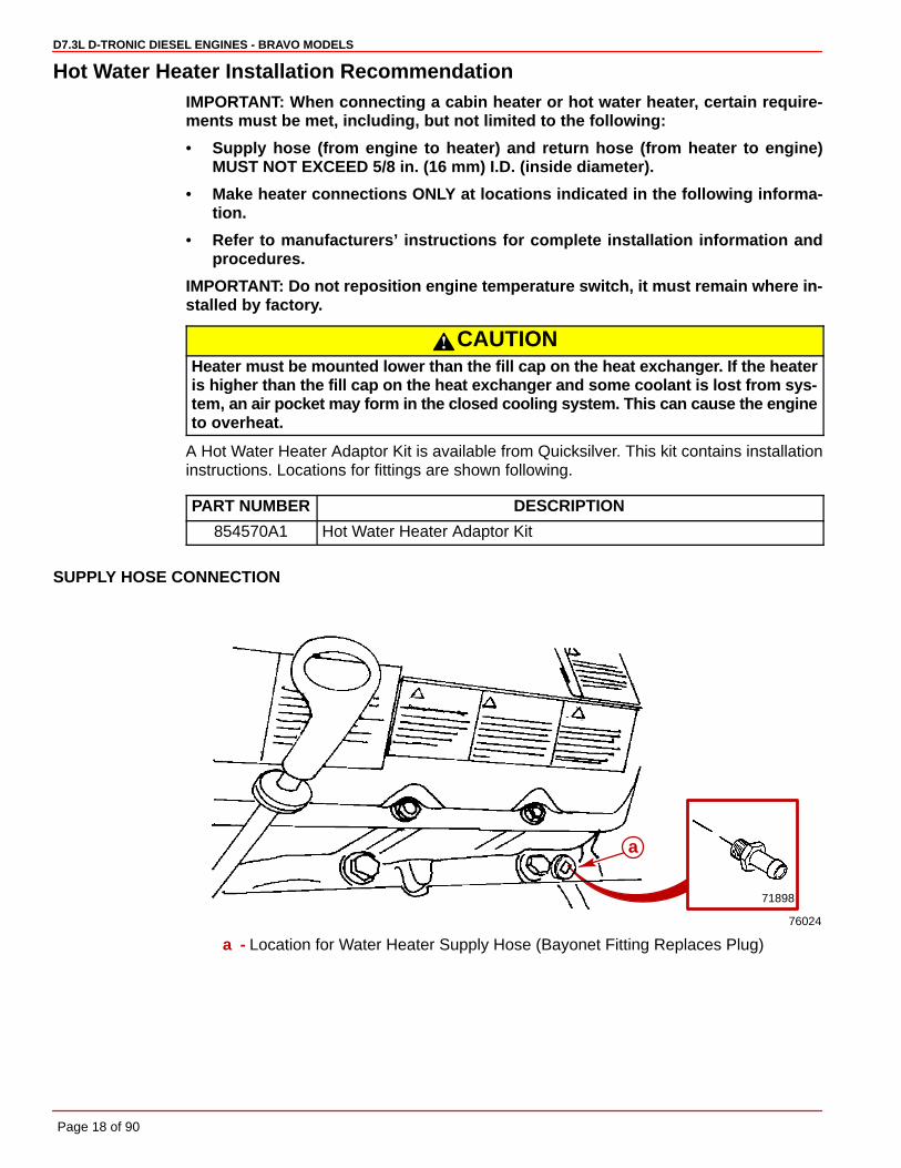
SUPPLY HOSE CONNECTION
76024
71898
a
a - Location for Water Heater Supply Hose (Bayonet Fitting Replaces Plug)
D7.3L D-TRONIC DIESEL ENGINES - BRAVO MODELS
Page 19 of 90
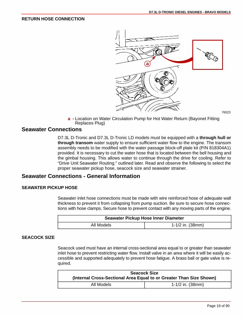
RETURN HOSE CONNECTION
76023
a
a - Location on Water Circulation Pump for Hot Water Return (Bayonet FittingReplaces Plug)
Seawater ConnectionsD7.3L D-Tronic and D7.3L D-Tronic LD models must be equipped with a through hull orthrough transom water supply to ensure sufficient water flow to the engine. The transomassembly needs to be modified with the water passage block-off plate kit (P/N 818304A1)provided. It is necessary to cut the water hose that is located between the bell housing andthe gimbal housing. This allows water to continue through the drive for cooling. Refer to“Drive Unit Seawater Routing.” outlined later. Read and observe the following to select theproper seawater pickup hose, seacock size and seawater strainer.
Seawater Connections - General Information
SEAWATER PICKUP HOSE
Seawater inlet hose connections must be made with wire reinforced hose of adequate wallthickness to prevent it from collapsing from pump suction. Be sure to secure hose connec-tions with hose clamps. Secure hose to prevent contact with any moving parts of the engine.
Seawater Pickup Hose Inner Diameter
All Models 1-1/2 in. (38mm)
SEACOCK SIZE
Seacock used must have an internal cross-sectional area equal to or greater than seawaterinlet hose to prevent restricting water flow. Install valve in an area where it will be easily ac-cessible and supported adequately to prevent hose fatigue. A brass ball or gate valve is re-quired.
Seacock Size(Internal Cross-Sectional Area Equal to or Greater Than Size Shown)
All Models 1-1/2 in. (38mm)
D7.3L D-TRONIC DIESEL ENGINES - BRAVO MODELS
Page 20 of 90
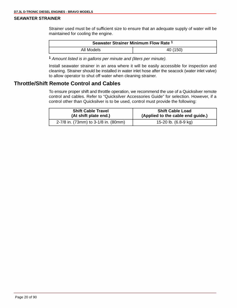
SEAWATER STRAINER
Strainer used must be of sufficient size to ensure that an adequate supply of water will bemaintained for cooling the engine.
Seawater Strainer Minimum Flow Rate 1
All Models 40 (150)
1 Amount listed is in gallons per minute and (liters per minute).
Install seawater strainer in an area where it will be easily accessible for inspection andcleaning. Strainer should be installed in water inlet hose after the seacock (water inlet valve)to allow operator to shut off water when cleaning strainer.
Throttle/Shift Remote Control and CablesTo ensure proper shift and throttle operation, we recommend the use of a Quicksilver remotecontrol and cables. Refer to “Quicksilver Accessories Guide” for selection. However, if acontrol other than Quicksilver is to be used, control must provide the following:
Shift Cable Travel(At shift plate end.)
Shift Cable Load(Applied to the cable end guide.)
2-7/8 in. (73mm) to 3-1/8 in. (80mm) 15-20 lb. (6.8-9 kg)

D7.3L D-TRONIC DIESEL ENGINES - BRAVO MODELS
Page 21 of 90
Steering Helm and CableTransom assembly is shipped with the steering cable guide tube preset for cables with enddimensions that comply with ABYC standards as outlined in the NMMA certification hand-book. The steering cable coupler nut must also have a means of locking it to the guide tubeas specified in ABYC requirements.
WARNINGFailure to use a steering cable locking device could cause loss of steering, whichcould cause damage to the boat and/or injury.
All current production Quicksilver Ride Guide steering cables have a self-locking couplernut and do not require an external locking device. (Other cable manufacturers also makecables with self-locking coupler nut.)
22060
a
a - Quicksilver Ride Guide Steering Cable Self-Locking Coupler Nut (Identified byGroove)
If using a steering cable that does not have a self-locking coupler nut, an external lockingdevice must be used.
c
e
fd
b
a
a - Steering Cableb - Grease Fittingc - Cotter Pind - Locking Sleeve (If Required - Must Be Ordered Separately)e - Cable Coupler Nutf - Cable Guide Tube

D7.3L D-TRONIC DIESEL ENGINES - BRAVO MODELS
Page 22 of 90
CAUTIONPOWER STEERING EQUIPPED UNITS ONLY: If steering cable with improper dimen-sions is installed, severe damage to transom assembly and/or steering system mayresult.
1. Steering cable must be the correct length, particularly when installed in larger boats.
2. Avoid sharp bends, kinks or loops in cable.
3. Fully extended steering cable end dimension must be as shown.
STEERING CABLE SPECIFICATIONS
21435
CL
a
b
c
d
g
hil
e
j
f
k
a - Coupler Nut - 7/8 - 14 UNF - 28 Threadb - 11-3/4 in. (298 mm) Min.c - Interface Pointd - 1/2 in. (12.700 mm) Max.e - .420 in. (10.668 mm) Min. Flatf - .102 in. (0.508 mm) Min. Radiusg - 5/8 in. (15.875 mm) Max. Diameter End Fittingh - 3/8 in. (9.525 mm)i - .385 in. (9.779 mm) Diameter Thru Hole, Chamfered Each Sidej - 1-3/8 in. (34.925 mm) Maxk - 5/8 in. (15.875 mm) Diameter Tubel - Mid-Travel Position - 16-7/8 in. (428.6 mm) Total Travel To Be 8 in. (203.2 mm)
Min. to 9 in. (228.6 mm) Max Travel Each Side of Mid-Travel Position - 4 in.(101.6 mm) Min., 4-1/2 in. (114.3 mm) Max.
21436
a
c
b
a - Steering Cable Mounting Flangeb - Center of Hole in Steering Cable Endc - 21-3/8 in. (543 mm) Max.

D7.3L D-TRONIC DIESEL ENGINES - BRAVO MODELS
Page 23 of 90
Transom Cutout
NOTICE to INSTALLER
Before Starting Installation Read “General Information” and “Installation Requirements”Sections Completely.
IMPORTANT: The following instructions will provide a sterndrive unit mounting loca-tion that is suitable for most boats. Best mounting location for a particular boat, how-ever, can be determined only by testing.
Bravo Models use items 1 - 4.
1. Below 25 m.p.h. (40 km/h): Subtract 1/2 in. (13mm) from “X” Dimension Shown.
2. Heavy Duty Applications: Subtract 1 in. (25mm) from “X” Dimension shown.
3. Above 25 m.p.h. (40 km/h): Use “X” Dimension shown.
4. Above 50 m.p.h. (80 km/h): The “X” Dimension can be increased to improve perform-ance in some applications, but pulling power (for skiing) will decrease. During testing,“X” Dimension should be increased 1/2 in. (13mm) at a time until desired performanceis achieved but in no case should it ever be increased by more than:
Bravo One/Two: 3 in. (76 mm) maximum.
Bravo Three: 1 in. (25 mm) maximum.
In ALL applications where cooling water is supplied through the sterndrive unit to theengine, extreme care should be taken when raising drive unit to ensure that the watersupply does not become aerated. Use a clear, water inlet hose to check incoming water foraeration. Monitor engine temperature gauge to ensure engine does not overheat.
In applications where cooling water is supplied to the engine by a fitting through thehull or transom , the sterndrive height will not cause cooling water aeration.
IMPORTANT: Damage to MerCruiser products caused by too high of an installedheight will not be covered by MerCruiser warranty.
D7.3L D-TRONIC DIESEL ENGINES - BRAVO MODELS
Page 24 of 90
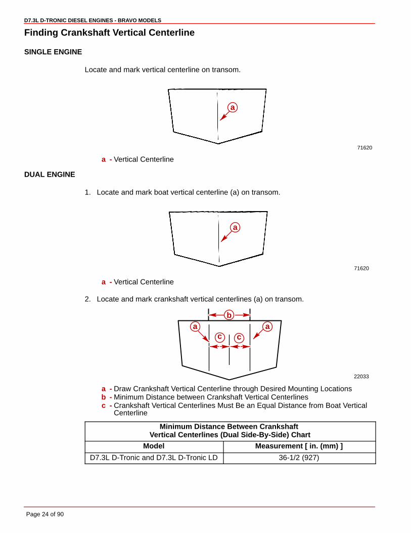
Finding Crankshaft Vertical Centerline
SINGLE ENGINE
Locate and mark vertical centerline on transom.
71620
a
a - Vertical Centerline
DUAL ENGINE
1. Locate and mark boat vertical centerline (a) on transom.
71620
a
a - Vertical Centerline
2. Locate and mark crankshaft vertical centerlines (a) on transom.
22033
ba a
c c
a - Draw Crankshaft Vertical Centerline through Desired Mounting Locationsb - Minimum Distance between Crankshaft Vertical Centerlinesc - Crankshaft Vertical Centerlines Must Be an Equal Distance from Boat Vertical
Centerline
Minimum Distance Between Crankshaft Vertical Centerlines (Dual Side-By-Side) Chart
Model Measurement [ in. (mm) ]
D7.3L D-Tronic and D7.3L D-Tronic LD 36-1/2 (927)
D7.3L D-TRONIC DIESEL ENGINES - BRAVO MODELS
Page 25 of 90
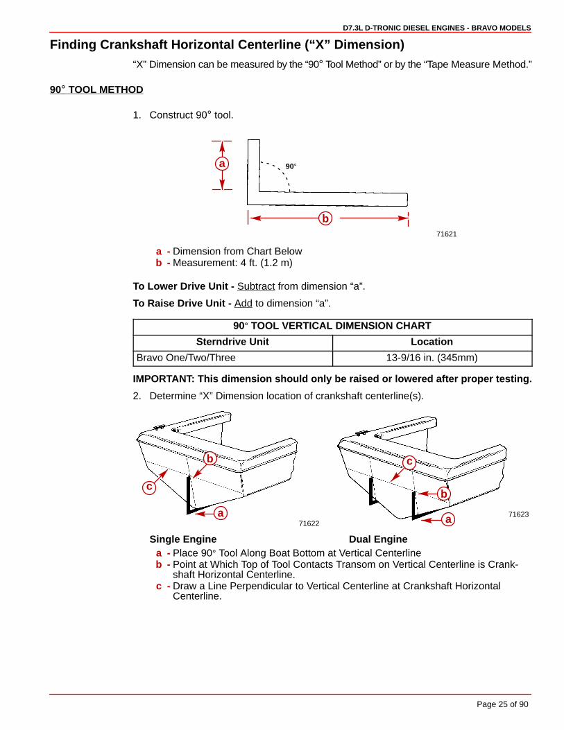
Finding Crankshaft Horizontal Centerline (“X” Dimension)“X” Dimension can be measured by the “90° Tool Method” or by the “Tape Measure Method.”
90° TOOL METHOD
1. Construct 90° tool.
71621
90°
b
a
a - Dimension from Chart Belowb - Measurement: 4 ft. (1.2 m)
To Lower Drive Unit - Subtract from dimension “a”.
To Raise Drive Unit - Add to dimension “a”.
90° TOOL VERTICAL DIMENSION CHART
Sterndrive Unit Location
Bravo One/Two/Three 13-9/16 in. (345mm)
IMPORTANT: This dimension should only be raised or lowered after proper testing.
2. Determine “X” Dimension location of crankshaft centerline(s).
7162271623
c
a
b c
b
a
Single Engine Dual Enginea - Place 90° Tool Along Boat Bottom at Vertical Centerlineb - Point at Which Top of Tool Contacts Transom on Vertical Centerline is Crank-
shaft Horizontal Centerline.c - Draw a Line Perpendicular to Vertical Centerline at Crankshaft Horizontal
Centerline.

D7.3L D-TRONIC DIESEL ENGINES - BRAVO MODELS
Page 26 of 90
TAPE MEASURE METHOD
Transom angle must be known, then measure “X” Dimension with tape measure.
1. Determine “X” Dimension from the following chart.
Tape Measure Method Chart
Model Bravo One / Two / Three
Transom Angle This dimension should only be raised or lowered after propertesting.
16° 14-5/16 in. (364 mm)
15° 14-1/4 in. (362 mm)
14° 14-3/16 in. (360 mm)
13° 14-1/8 in. (359 mm)
12° 14-1/16 in. (357 mm)
11° 14 in. (356 mm)
10° 13-15/16 (354 mm)
2. Measure and layout horizontal centerlines as shown.
7162271623
c
d
b
d
b
c
aa
Single Engine Dual Enginea - “X” Dimension (from Chart) that Corresponds to Transom Angle - Measure Up
from Boat Bottom with Tape Measureb - Crankshaft Horizontal Centerlinec - Vertical Centerlined - Draw a Line Perpendicular to Vertical Centerline at Crankshaft Horizontal
Centerline

D7.3L D-TRONIC DIESEL ENGINES - BRAVO MODELS
Page 27 of 90
Cutting Transom
Transom cutout can be made by either using the Template [shipped with transom assembly]or the Transom Drilling Fixture Kit (purchased separately).
Follow instructions indicated on template or provided with drilling fixture.
IMPORTANT: Read and observe the following information:
• Be certain that centerlines on either the template or transom drilling fixture alignwith lines previously marked on transom.
• Be sure to drill 1/4 in. pilot holes (for hole saw guide) at a 60 ° angle and to cut onthe line when making transom cutout. If cutout is made incorrectly, drive unitsteering lever may contact transom, thus limiting steering travel.
• Seal inside edge of transom cutout opening with a suitable sealant to prevent wa-ter absorption and deterioration of transom.
50017
Transom Cutout Template
22056
Transom Drilling Fixture Kit

D7.3L D-TRONIC DIESEL ENGINES - BRAVO MODELS
Page 28 of 90
Checking Transom Thickness
Ensure transom surface thickness and flatness conform to minimums specified in “Installa-tion Requirements” listed previously.
NOTE: Transom must be between 2” (51 mm) and 2-1/4” (57 mm) a distance of 8” (203 mm)to either side of the vertical centerline.
a
b
c
a - Measuring Thicknessb - Measuring Flatnessc - Suitable Mandrel To Check For Uniform Transom Thickness.

D7.3L D-TRONIC DIESEL ENGINES - BRAVO MODELS
Page 29 of 90
Installing Transom Assembly
Gimbal Housing1. Carefully remove transom assembly from shipping carton.
2. Remove and read all tags which are attached to transom assembly.
IMPORTANT: Read and observe the following regarding your engine and the thru-propeller exhaust system :
• With any application, installation of an exhaust tube will increase exhaust noise.
• With Bravo One, Bravo Two and Bravo Three Drive Models the exhaust bellowsmust be removed and an exhaust tube MUST BE INSTALLED.
NOTE: Exhaust tube parts (Quicksilver Part Number 78458A1) are provided with a BravoThree Drive. They are located in the drive unit box.
3. Install exhaust tube on gimbal housing as follows:
a. Remove and discard clamps and exhaust bellows.
CAUTIONExhaust tube clamp may corrode if grounding clip is not installed.
b. Install grounding clip on tube.
NOTE: Bellows adhesive is not used when installing an exhaust tube.
c. Position tube so that “SIDE” markings on tube are facing toward the right and leftsides.
d. Install clamp.
e. Tighten clamp. Torque to 35 lb-in. (4 Nm).
22184
22184
e
d
cb
a
a - Exhaust Tubeb - Clampc - “Side” Markingd - Exhaust Tubee - Grounding Clip
D7.3L D-TRONIC DIESEL ENGINES - BRAVO MODELS
Page 30 of 90
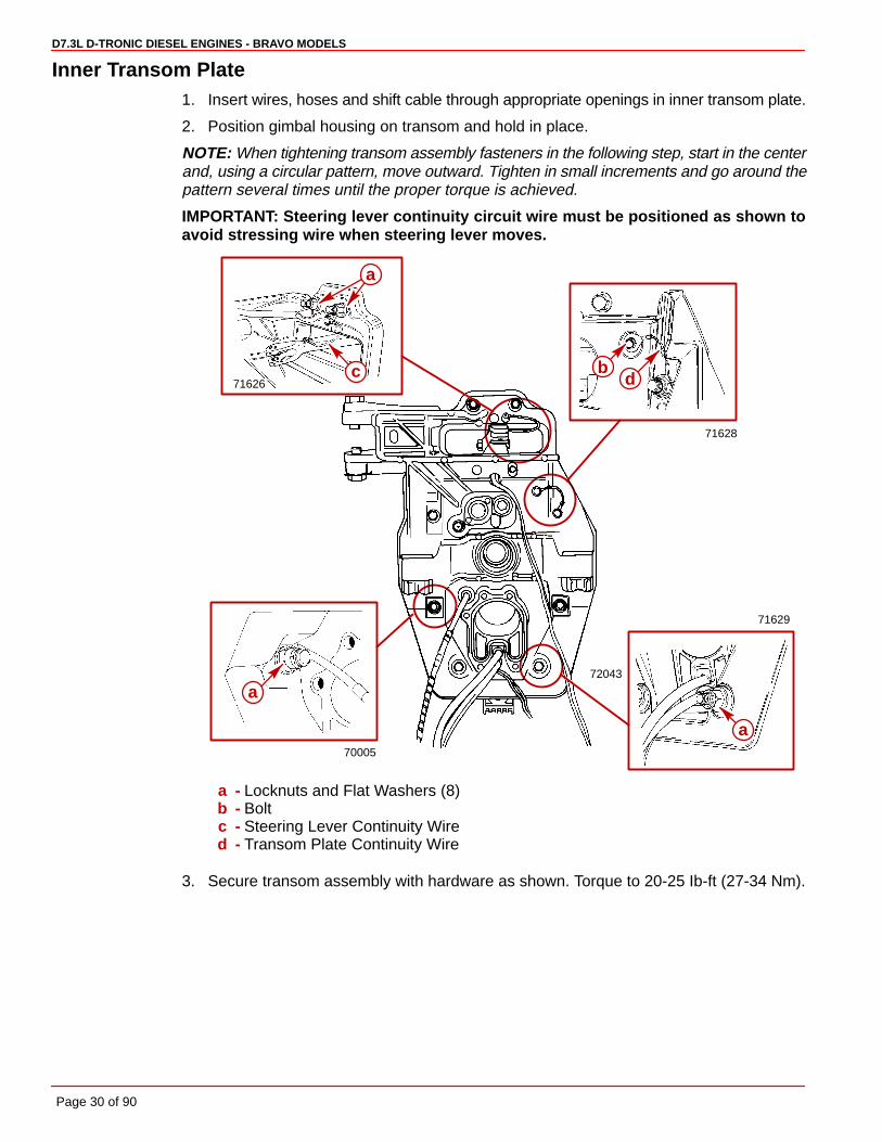
Inner Transom Plate1. Insert wires, hoses and shift cable through appropriate openings in inner transom plate.
2. Position gimbal housing on transom and hold in place.
NOTE: When tightening transom assembly fasteners in the following step, start in the centerand, using a circular pattern, move outward. Tighten in small increments and go around thepattern several times until the proper torque is achieved.
IMPORTANT: Steering lever continuity circuit wire must be positioned as shown toavoid stressing wire when steering lever moves.
72043
71626
71628
70005
71629
c
a
a
a
bd
a - Locknuts and Flat Washers (8)b - Boltc - Steering Lever Continuity Wired - Transom Plate Continuity Wire
3. Secure transom assembly with hardware as shown. Torque to 20-25 Ib-ft (27-34 Nm).

D7.3L D-TRONIC DIESEL ENGINES - BRAVO MODELS
Page 31 of 90
Power Trim Pump1. Mount pump in desired location.
IMPORTANT: Make hydraulic connections as quickly as possible to prevent oil fromleaking out of system. Be careful not to cross-thread or overtighten hose fittings.
75126
50630
75127
50632
a
c
d
e
fg
b
a - Black Hose (UP Circuit)b - Gray Hose (DOWN Circuit)c - Harness Connectord - Clampe - Trim Limit Switch Wire (with Blue Sleeve) - to BLUE/WHITE Harness Wiref - Trim Limit Switch Wire (with Purple Sleeve) to PURPLE/WHITE Harness Wireg - Wire Retainer and Sta-Strap
2. Connect hydraulic hoses to trim pump. Torque fittings to 100-150 lb-in. (11-16 Nm).
3. Connect power trim pump control harness to trim pump. Secure with clamp.
4. Connect trim limit switch wires and secure with wire retainer and sta-strap.
D7.3L D-TRONIC DIESEL ENGINES - BRAVO MODELS
Page 32 of 90
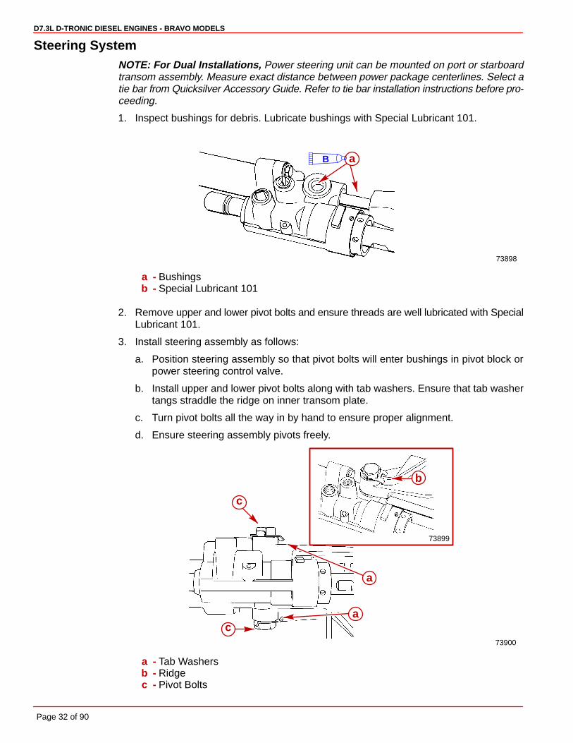
Steering SystemNOTE: For Dual Installations, Power steering unit can be mounted on port or starboardtransom assembly. Measure exact distance between power package centerlines. Select atie bar from Quicksilver Accessory Guide. Refer to tie bar installation instructions before pro-ceeding.
1. Inspect bushings for debris. Lubricate bushings with Special Lubricant 101.
73898
aB
a - Bushingsb - Special Lubricant 101
2. Remove upper and lower pivot bolts and ensure threads are well lubricated with SpecialLubricant 101.
3. Install steering assembly as follows:
a. Position steering assembly so that pivot bolts will enter bushings in pivot block orpower steering control valve.
b. Install upper and lower pivot bolts along with tab washers. Ensure that tab washertangs straddle the ridge on inner transom plate.
c. Turn pivot bolts all the way in by hand to ensure proper alignment.
d. Ensure steering assembly pivots freely.
73900
73899
b
c
a
ac
a - Tab Washersb - Ridgec - Pivot Bolts

D7.3L D-TRONIC DIESEL ENGINES - BRAVO MODELS
Page 33 of 90
4. Torque pivot bolts to 25 lb-ft (34 Nm). Bend washer tabs against corresponding flats onbolt heads.
CAUTIONMOVING THE CONTROL VALVE RAM with the hoses disconnected will expel fluidfrom the ports. Wear eye protection.
5. The cylinder ram may be stiff and difficult to move when you attempt to pull it out or pushit in for installation. First move the spool assembly in the direction(s) shown below.
74145
74144
a
a
a - Ports
6. Connect clevis to steering lever. Lubricate clevis pin with Special Lubricant 101. Be sureto spread both ends of the cotter pin.
71904
ab
c
d
a - Clevisb - Steering Leverc - Clevis Pind - Cotter Pin
D7.3L D-TRONIC DIESEL ENGINES - BRAVO MODELS
Page 34 of 90
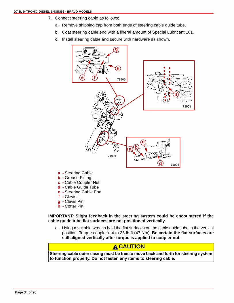
7. Connect steering cable as follows:
a. Remove shipping cap from both ends of steering cable guide tube.
b. Coat steering cable end with a liberal amount of Special Lubricant 101.
c. Install steering cable and secure with hardware as shown.
71901
71906
71903
g
h
fe
d
a bc
73901
d
a - Steering Cableb - Grease Fittingc - Cable Coupler Nutd - Cable Guide Tubee - Steering Cable Endf - Clevisg - Clevis Pinh - Cotter Pin
IMPORTANT: Slight feedback in the steering system could be encountered if thecable guide tube flat surfaces are not positioned vertically.
d. Using a suitable wrench hold the flat surfaces on the cable guide tube in the verticalposition. Torque coupler nut to 35 lb-ft (47 Nm). Be certain the flat surfaces arestill aligned vertically after torque is applied to coupler nut.
CAUTIONSteering cable outer casing must be free to move back and forth for steering systemto function properly. Do not fasten any items to steering cable.
D7.3L D-TRONIC DIESEL ENGINES - BRAVO MODELS
Page 35 of 90
Speedometer PickupIMPORTANT: Do not disturb plug at speedometer fitting if no speedometer is to befitted, or if an alternate speedometer pickup will be used.
1. Remove plug from speedometer pickup tube fitting.
70037
a
b
a - Fitting Plugb - Speedometer Pickup Tube Fitting
2. Apply Perfect Seal to threads of barb fitting. Install and torque to 10-15 Ib. in. (1.1-1.7N⋅m).
70015
a
a - Barb Fitting
3. Connect hose from speedometer to barb fitting. Secure hose with cable tie.
4. Mount speedometer hose to transom with hose clip and screw. Hose must not come incontact with steering system components or the engine coupler and drive shaft.
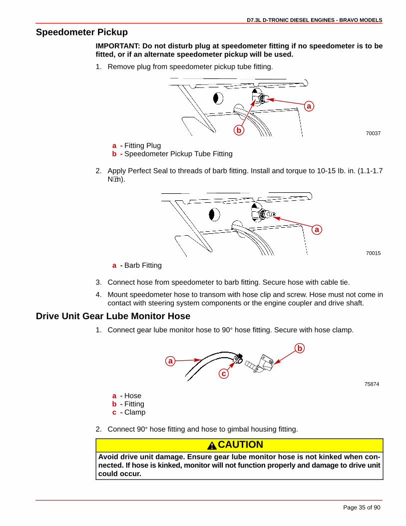
Drive Unit Gear Lube Monitor Hose1. Connect gear lube monitor hose to 90° hose fitting. Secure with hose clamp.
75874
a
b
c
a - Hoseb - Fittingc - Clamp
2. Connect 90° hose fitting and hose to gimbal housing fitting.
CAUTIONAvoid drive unit damage. Ensure gear lube monitor hose is not kinked when con-nected. If hose is kinked, monitor will not function properly and damage to drive unitcould occur.

D7.3L D-TRONIC DIESEL ENGINES - BRAVO MODELS
Page 36 of 90
3. Route hose to monitor bottle mounted on engine and cut off excess hose.
IMPORTANT: Avoid using excessive hose when routing to gear lube monitor. Hoseshould be routed directly, in as straight a line as possible, to avoid low spots (traps)in the system.
7531374235 75874
a
d
c
b
a - Hoseb - 90° Hose Fittingc - Gimbal Housing Fittingd - Gear Lube Monitor
IMPORTANT: Hose must not come in contact with steering system components or theengine coupler and drive shaft.
Exhaust Water BypassMerCruiser D7.3L D-Tronic Models are equipped with an exhaust water bypass system.The purpose of this exhaust water bypass system is to calibrate the exhaust back pressureand to provide additional cooling to the drive assembly.
The exhaust water bypass outlet (provided with instructions for installation) must beinstalled within the Preferred or Alternative Area as indicated on the template. Refer to thefull scale template (provided). Ensure that the water outlet snout is positioned in such a waythat the water will flow over the top (preferred location) or upper side (alternative location)of the Drive Assembly.
ab
a - Templateb - Preferred Exhaust Water Bypass Routing
1. Cut template outline as required. Position on transom.
2. Drill or cut hole as indicated on template.
3. Use silicone or other Marine sealer and install exhaust water outlet on boat transom.
4. Exhaust outlet on transom must be grounded to inner transom plate assembly. Installground strap provided.
5. Cut hose to required length. Install between exhaust elbow fitting and exhaust water by-pass outlet. Use double clamps on hose connections.

D7.3L D-TRONIC DIESEL ENGINES - BRAVO MODELS
Page 37 of 90
Drive Unit Seawater RoutingSeawater for engine cooling is supplied through a separate seawater pickup, not throughthe drive unit. Therefore, it is necessary to block the drive unit seawater passage and to cutthe water hose that is located between the bell housing and the gimbal housing. This allowswater to continue to circulate through the drive unit for cooling.
BLOCK-OFF PLATE
1. Install block-off plate with gasket. Torque screws with star washers to 45 lb-in. (5 Nm).
75313c
a
b
75314
a bc
a - Plateb - Gasketc - Screw And Washer
CAUTIONAvoid drive unit damage. Quick release button on gear lube monitor 90° hose fittingmay not lock on gimbal housing if touching or depressed by block-off plate. Ensurequick release button does not contact block-off plate. Failure to do so could resultin a loose 90° fitting causing a loss of gear lube and damage to drive unit.
2. Position quick release button on hose fitting away from block-off plate. Release buttonmust not contact block-off plate.
71998
d
OK
b
d
a
c
a - Water Inlet Fittingb - Star Washer and Screwc - 90° Hose Fittingd - Quick Release Button
D7.3L D-TRONIC DIESEL ENGINES - BRAVO MODELS
Page 38 of 90
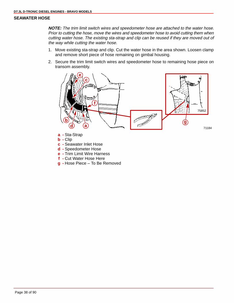
SEAWATER HOSE
NOTE: The trim limit switch wires and speedometer hose are attached to the water hose.Prior to cutting the hose, move the wires and speedometer hose to avoid cutting them whencutting water hose. The existing sta-strap and clip can be reused if they are moved out ofthe way while cutting the water hose.
1. Move existing sta-strap and clip. Cut the water hose in the area shown. Loosen clampand remove short piece of hose remaining on gimbal housing.
2. Secure the trim limit switch wires and speedometer hose to remaining hose piece ontransom assembly.
75852
71184a
bd
f
ce
g
a - Sta-Strapb - Clipc - Seawater Inlet Hosed - Speedometer Hosee - Trim Limit Wire Harnessf - Cut Water Hose Hereg - Hose Piece – To Be Removed
D7.3L D-TRONIC DIESEL ENGINES - BRAVO MODELS
Page 39 of 90
Engine InstallationEngine Preparation
1. Remove and read all tags attached to engine.
2. Remove all hardware that secures engine to shipping container.
3. Loosen fasteners and remove exhaust pipe and exhaust hose from pallet.
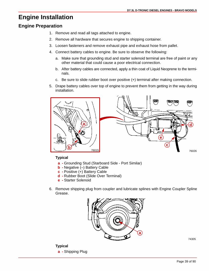
4. Connect battery cables to engine. Be sure to observe the following:
a. Make sure that grounding stud and starter solenoid terminal are free of paint or anyother material that could cause a poor electrical connection.
b. After battery cables are connected, apply a thin coat of Liquid Neoprene to the termi-nals.
c. Be sure to slide rubber boot over positive (+) terminal after making connection.
5. Drape battery cables over top of engine to prevent them from getting in the way duringinstallation.
76026
a
b
e
d
c76015
Typicala - Grounding Stud (Starboard Side - Port Similar)b - Negative (–) Battery Cablec - Positive (+) Battery Cabled - Rubber Boot (Slide Over Terminal)e - Starter Solenoid
6. Remove shipping plug from coupler and lubricate splines with Engine Coupler SplineGrease.
74305
a
Typicala - Shipping Plug

D7.3L D-TRONIC DIESEL ENGINES - BRAVO MODELS
Page 40 of 90
Transom PreparationIMPORTANT: Exhaust pipe and gimbal housing mating surfaces must be clean andfree of nicks and scratches, and O-ring must be properly seated in groove, or waterand exhaust may leak into boat.
22059
a
b
a - Gimbal Housing Mating Surfaceb - O-ring
1. Install exhaust pipe assembly as shown, using four (4) bolts and thick lockwashers.Torque bolts to 20-25 lb-ft (27-34 Nm).
2. Position rear engine mount attaching hardware on inner transom plate mounts asshown.
50659
b
c
a
ad
e
a - Exhaust Pipeb - Bolts and Thick Lockwashers (4)c - Fiber Washersd - Double-Wound Lockwasherse - Locknuts

D7.3L D-TRONIC DIESEL ENGINES - BRAVO MODELS
Page 41 of 90
Installing Engine / Alignment1. Attach a suitable sling to lifting eyes on engine and adjust so that engine is level when
suspended.
2. Lift engine into position (in boat), using an overhead hoist.
CAUTIONWhen lowering engine into position DO NOT set engine on shift cable. Shift cableouter casing can be crushed causing difficult or improper shifting.
76012
76016
76021
a
b
c
a - Front Engine Lifting Eyeb - Rear Engine Lifting Eyec - Suitable Sling
D7.3L D-TRONIC DIESEL ENGINES - BRAVO MODELS
Page 42 of 90
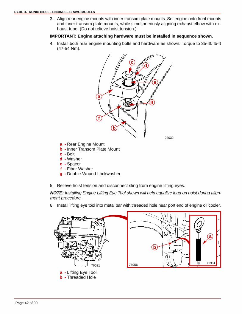
3. Align rear engine mounts with inner transom plate mounts. Set engine onto front mountsand inner transom plate mounts, while simultaneously aligning exhaust elbow with ex-haust tube. (Do not relieve hoist tension.)nd
IMPORTANT: Engine attaching hardware must be installed in sequence shown.
4. Install both rear engine mounting bolts and hardware as shown. Torque to 35-40 lb-ft(47-54 Nm).
22032
a
c
b
d
g
f
e
a - Rear Engine Mountb - Inner Transom Plate Mountc - Boltd - Washere - Spacerf - Fiber Washerg - Double-Wound Lockwasher
5. Relieve hoist tension and disconnect sling from engine lifting eyes.
NOTE: Installing Engine Lifting Eye Tool shown will help equalize load on hoist during align-ment procedure.
6. Install lifting eye tool into metal bar with threaded hole near port end of engine oil cooler.
759567602171961
b
a
a - Lifting Eye Toolb - Threaded Hole
D7.3L D-TRONIC DIESEL ENGINES - BRAVO MODELS
Page 43 of 90
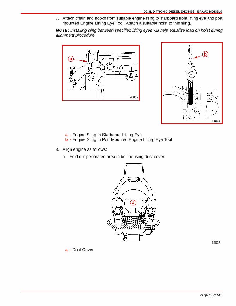
7. Attach chain and hooks from suitable engine sling to starboard front lifting eye and portmounted Engine Lifting Eye Tool. Attach a suitable hoist to this sling.
NOTE: Installing sling between specified lifting eyes will help equalize load on hoist duringalignment procedure.
76012
ab
71961
a - Engine Sling In Starboard Lifting Eyeb - Engine Sling In Port Mounted Engine Lifting Eye Tool
8. Align engine as follows:
a. Fold out perforated area in bell housing dust cover.
22027
a
a - Dust Cover

D7.3L D-TRONIC DIESEL ENGINES - BRAVO MODELS
Page 44 of 90
CAUTIONDO NOT use an alignment tool from another manufacturer. Alignment tools otherthan Quicksilver Alignment Tool may cause improper alignment and damage togimbal bearing and/or engine coupler.
CAUTIONTo avoid damage to gimbal bearing, engine coupler, or alignment tool:
� DO NOT attempt to force alignment tool!
� DO NOT raise or lower engine with alignment tool inserted (or partially inserted)in gimbal bearing or engine coupler.
b. Attempt to insert the solid end of the alignment tool thru the gimbal bearing and intothe engine coupler splines.
c. If the tool does not fit, remove it and carefully raise or lower the front end of the en-gine, as necessary, and attempt to insert the alignment tool.
d. Repeat step “c” until the alignment tool installs easily (SLIDES FREELY WITH TWOFINGERS) all the way into and out of engine coupler splines. Do not check by turn-ing.
22029
73345 73794
a b
a
cd
a - Alignment Tool (Use Only Recommended Alignment Tool)b - Insert This End Of Alignment Tool Through Gimbal Housing Assemblyc - Gimbal Bearingd - Engine Coupler
D7.3L D-TRONIC DIESEL ENGINES - BRAVO MODELS
Page 45 of 90
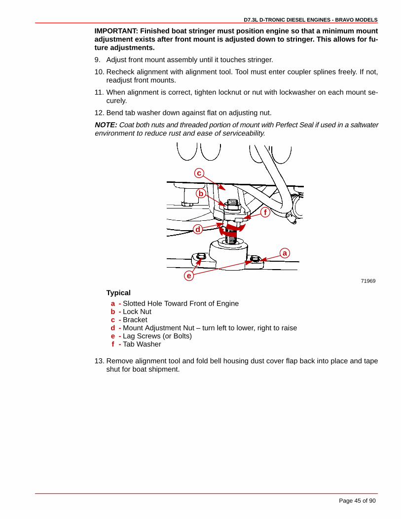
IMPORTANT: Finished boat stringer must position engine so that a minimum mountadjustment exists after front mount is adjusted down to stringer. This allows for fu-ture adjustments.
9. Adjust front mount assembly until it touches stringer.
10. Recheck alignment with alignment tool. Tool must enter coupler splines freely. If not,readjust front mounts.
11. When alignment is correct, tighten locknut or nut with lockwasher on each mount se-curely.
12. Bend tab washer down against flat on adjusting nut.
NOTE: Coat both nuts and threaded portion of mount with Perfect Seal if used in a saltwaterenvironment to reduce rust and ease of serviceability.
71969
a
b
c
e
f
d
Typicala - Slotted Hole Toward Front of Engineb - Lock Nutc - Bracketd - Mount Adjustment Nut – turn left to lower, right to raisee - Lag Screws (or Bolts)f - Tab Washer
13. Remove alignment tool and fold bell housing dust cover flap back into place and tapeshut for boat shipment.

D7.3L D-TRONIC DIESEL ENGINES - BRAVO MODELS
Page 46 of 90
Engine Connections
Quicksilver Seawater Pickup and Seacock1. Drill a 2 in. (50mm) hole thru hull in appropriate location (Refer to “Installation Require-
ments.”).
2. Apply marine caulking (sealer) to mounting surface on seawater pickup (thru-hull fitting)where hull contact will occur when installed.
3. Ensure slots in water pickup are facing forward and install water pickup. Position wash-er on fitting and install large nut. Tighten nut securely.
70355
70589fa
ed
e cb
a
f
a - Seawater Pickup (Thru-Hull Fitting)b - Washerc - Large Nutd - Hull of Boate - Marine Caulkingf - Slots Facing Forward (Toward Bow of Boat)
4. Install seacock on seawater pickup. Tighten securely.
5. Install 1-1/2 in. (38mm) hose connector on seacock. Tighten securely.
70355 70355
ab
c
a - Seacockb - Seawater Pickup (Thru-Hull Fitting)c - 1-1/2 in. (38mm) Hose Connector
IMPORTANT: Seawater hose used must be wire reinforced to avoid collapsing hosewhen suction is created by seawater pump impeller.
D7.3L D-TRONIC DIESEL ENGINES - BRAVO MODELS
Page 47 of 90
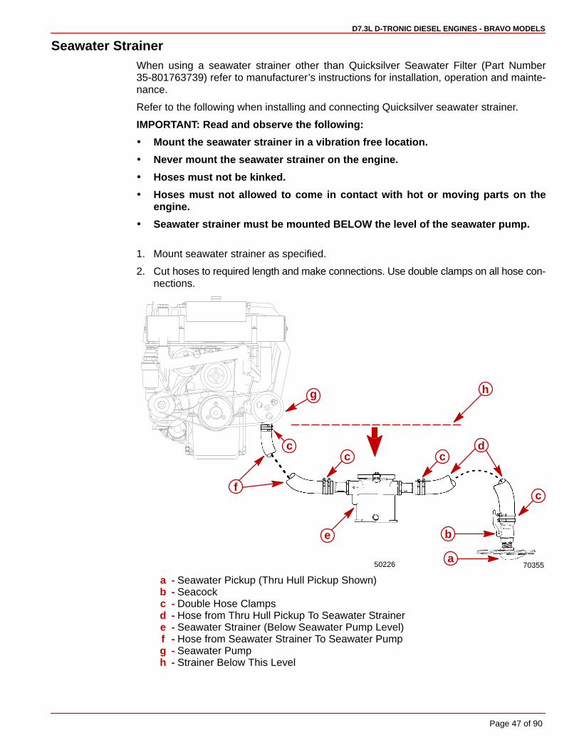
Seawater StrainerWhen using a seawater strainer other than Quicksilver Seawater Filter (Part Number35-801763739) refer to manufacturer’s instructions for installation, operation and mainte-nance.
Refer to the following when installing and connecting Quicksilver seawater strainer.
IMPORTANT: Read and observe the following:
� Mount the seawater strainer in a vibration free location.
� Never mount the seawater strainer on the engine.
� Hoses must not be kinked.
� Hoses must not allowed to come in contact with hot or moving parts on theengine.
� Seawater strainer must be mounted BELOW the level of the seawater pump.
1. Mount seawater strainer as specified.
2. Cut hoses to required length and make connections. Use double clamps on all hose con-nections.
50226 70355a
b
c
cc
e
d
f
c
g h
a - Seawater Pickup (Thru Hull Pickup Shown)b - Seacockc - Double Hose Clampsd - Hose from Thru Hull Pickup To Seawater Strainere - Seawater Strainer (Below Seawater Pump Level)f - Hose from Seawater Strainer To Seawater Pumpg - Seawater Pumph - Strainer Below This Level
D7.3L D-TRONIC DIESEL ENGINES - BRAVO MODELS
Page 48 of 90
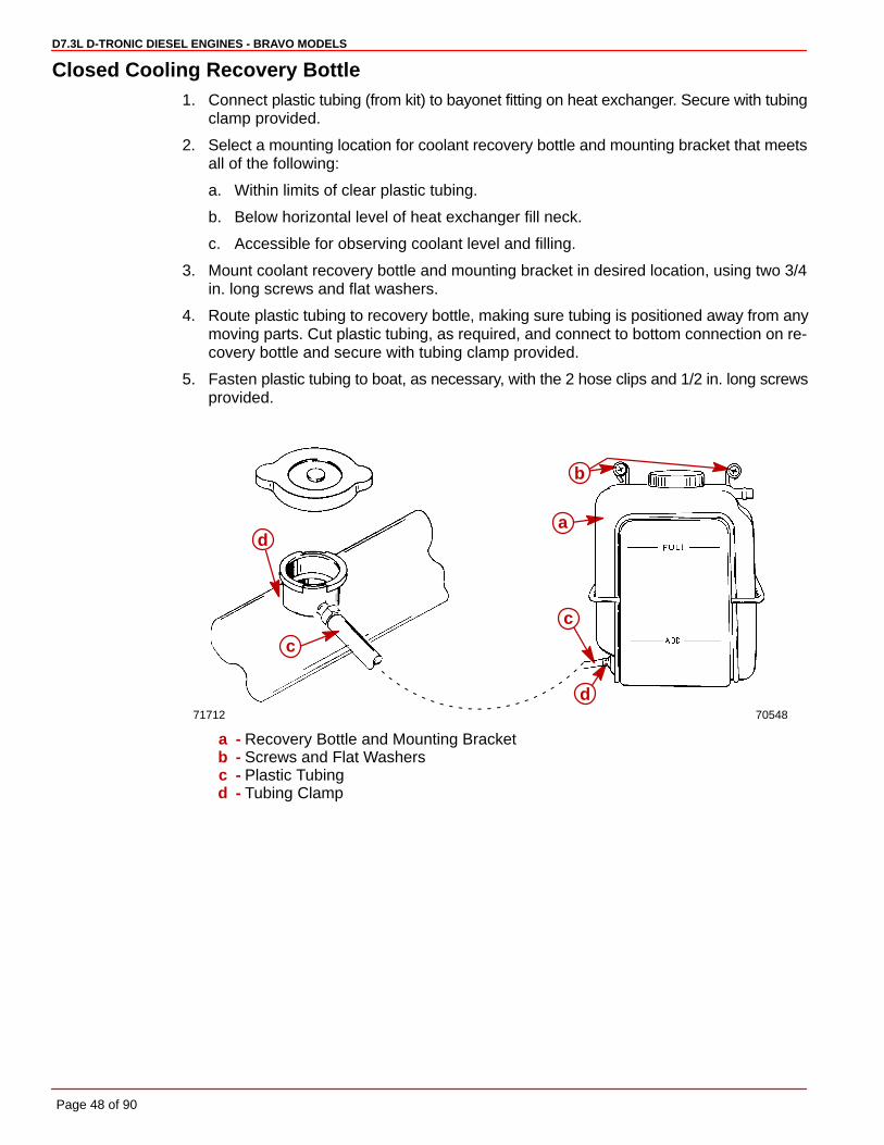
Closed Cooling Recovery Bottle1. Connect plastic tubing (from kit) to bayonet fitting on heat exchanger. Secure with tubing
clamp provided.
2. Select a mounting location for coolant recovery bottle and mounting bracket that meetsall of the following:
a. Within limits of clear plastic tubing.
b. Below horizontal level of heat exchanger fill neck.
c. Accessible for observing coolant level and filling.
3. Mount coolant recovery bottle and mounting bracket in desired location, using two 3/4in. long screws and flat washers.
4. Route plastic tubing to recovery bottle, making sure tubing is positioned away from anymoving parts. Cut plastic tubing, as required, and connect to bottom connection on re-covery bottle and secure with tubing clamp provided.
5. Fasten plastic tubing to boat, as necessary, with the 2 hose clips and 1/2 in. long screwsprovided.
7054871712
a
b
c
d
c
d
a - Recovery Bottle and Mounting Bracketb - Screws and Flat Washersc - Plastic Tubingd - Tubing Clamp
D7.3L D-TRONIC DIESEL ENGINES - BRAVO MODELS
Page 49 of 90
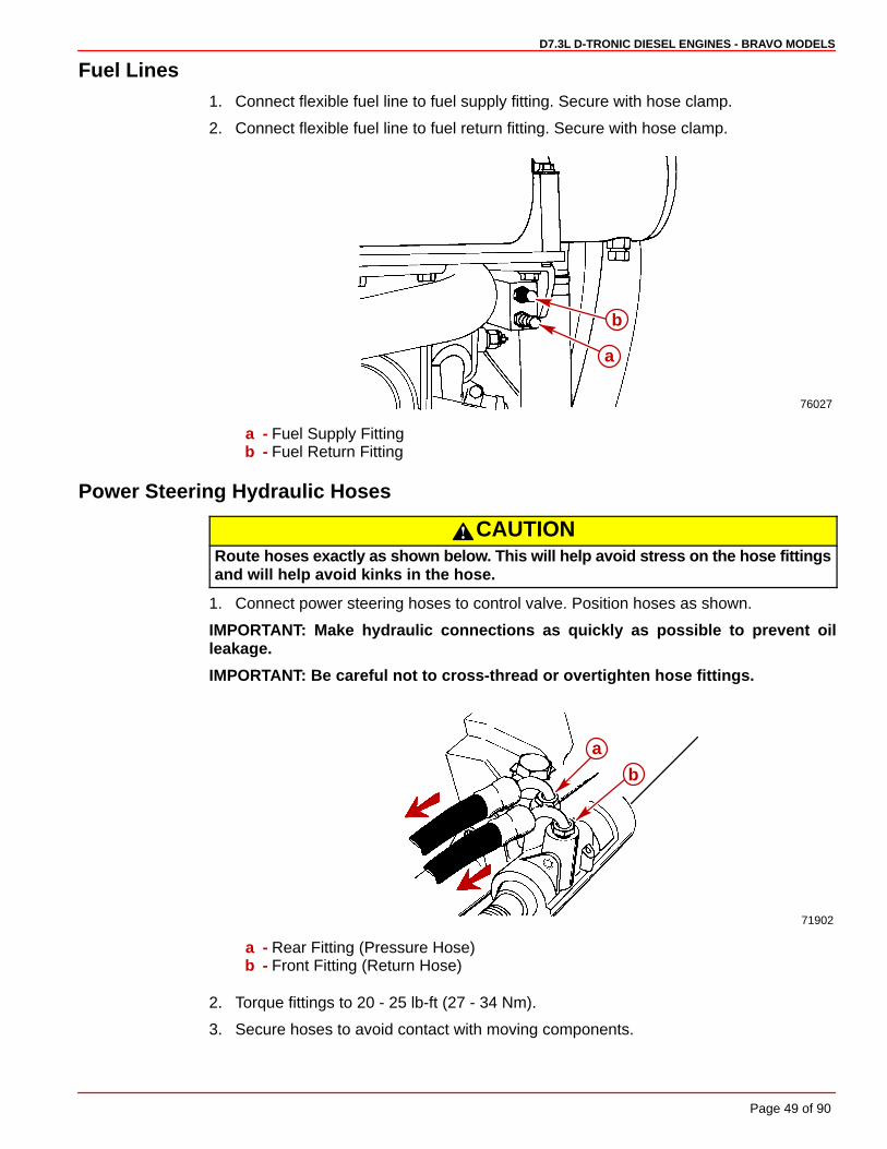
Fuel Lines1. Connect flexible fuel line to fuel supply fitting. Secure with hose clamp.
2. Connect flexible fuel line to fuel return fitting. Secure with hose clamp.
76027
a
b
a - Fuel Supply Fittingb - Fuel Return Fitting
Power Steering Hydraulic Hoses
CAUTIONRoute hoses exactly as shown below. This will help avoid stress on the hose fittingsand will help avoid kinks in the hose.
1. Connect power steering hoses to control valve. Position hoses as shown.
IMPORTANT: Make hydraulic connections as quickly as possible to prevent oilleakage.
IMPORTANT: Be careful not to cross-thread or overtighten hose fittings.
71902
a
b
a - Rear Fitting (Pressure Hose)b - Front Fitting (Return Hose)
2. Torque fittings to 20 - 25 lb-ft (27 - 34 Nm).
3. Secure hoses to avoid contact with moving components.

D7.3L D-TRONIC DIESEL ENGINES - BRAVO MODELS
Page 50 of 90
Exhaust System1. Tighten exhaust tube hose clamps securely.
76106
dc
ba
Typicala - Elbowb - Tubec - Hose Clamps (4)d - Pipe
Electrical Connections
CONTINUITY CIRCUIT
1. Connect continuity circuit wire (supplied with engine package) from engine to transomassembly. Tighten inner transom plate screw securely.
74217
a
b
c
a - Flywheel Housing Screw / Studb - Continuity Circuit Wirec - Inner Transom Plate Grounding Screw

D7.3L D-TRONIC DIESEL ENGINES - BRAVO MODELS
Page 51 of 90
INSTRUMENTS AND EXTENSION HARNESSES
NOTE: If using other than Quicksilver instrumentation and harnesses, refer to manufactur-ers’ instructions.
1. Follow the appropriate instructions “a”, “b” and/or “c”, depending upon boat configura-tion:
a. Prepare dash openings and/or mount gauges according to instructions providedwith individual gauges.
b. Prepare dash opening and/or mount Engine System Monitor Panel to dashboard fol-lowing Instruction Sheet/Template 90-806330.
c. Extend wires through dash openings and/or connect all instrument wiring harnessleads to the individual gauges and Engine System Monitor Panel. Refer to Quicksil-ver Instrumentation Wiring Diagram, wire identification tags and instructions pro-vided with individual gauges and kits.
2. The switch provided for the audio warning test and panel (dash) lights is a three-positiontoggle switch. It must be wired and installed correctly to provide proper operation of thesystems. Refer to the following special installation instructions:
a. Hold the switch in your hand and press the switch toggle lever into its spring loadedmomentary position. You must install the switch so that the “spring loaded”, AudioTest end of the switch is oriented DOWN once the panel is installed in the boat.
IMPORTANT: The decal on the side of the switch with the arrow and the word “UP”refer to the position of the switch when installed on the panel . The circled numbersrefer to wire terminals.
b. Install jamb nut, and then locking washer, on switch threaded portion. Secure to pan-el using knurled nut. Tighten securely, to prevent switch from turning in hole. DONOT overtighten.
71886
73369
ÉÉÉ
87-805675
UP
12
3
eU
Pa
b
c f b
ead
1
2
34
5
6
Typicala - Audio Test/Panel Light Switchb - Spring-Loaded Audio Test Portion (Direction of Movement DOWN When
Installed)c - Terminal Number(s)d - Terminal(s)e - Jamb Nutf - Locking Washer
D7.3L D-TRONIC DIESEL ENGINES - BRAVO MODELS
Page 52 of 90
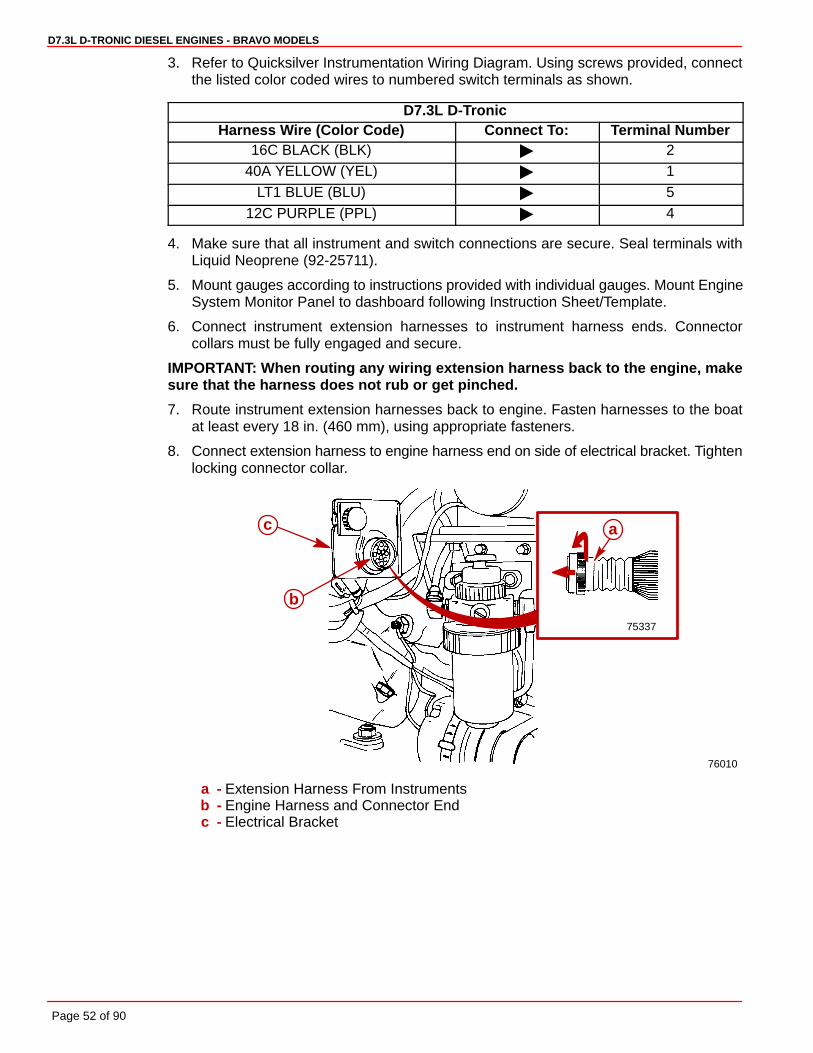
3. Refer to Quicksilver Instrumentation Wiring Diagram. Using screws provided, connectthe listed color coded wires to numbered switch terminals as shown.
D7.3L D-TronicHarness Wire (Color Code) Connect To: Terminal Number
16C BLACK (BLK) � 240A YELLOW (YEL) � 1
LT1 BLUE (BLU) � 512C PURPLE (PPL) � 4
4. Make sure that all instrument and switch connections are secure. Seal terminals withLiquid Neoprene (92-25711).
5. Mount gauges according to instructions provided with individual gauges. Mount EngineSystem Monitor Panel to dashboard following Instruction Sheet/Template.
6. Connect instrument extension harnesses to instrument harness ends. Connectorcollars must be fully engaged and secure.
IMPORTANT: When routing any wiring extension harness back to the engine, makesure that the harness does not rub or get pinched.
7. Route instrument extension harnesses back to engine. Fasten harnesses to the boatat least every 18 in. (460 mm), using appropriate fasteners.
8. Connect extension harness to engine harness end on side of electrical bracket. Tightenlocking connector collar.
75337
76010
a
b
c
a - Extension Harness From Instrumentsb - Engine Harness and Connector Endc - Electrical Bracket

D7.3L D-TRONIC DIESEL ENGINES - BRAVO MODELS
Page 53 of 90
NEUTRAL SAFETY SWITCH CONNECTION
1. Connect neutral safety switch wires at instrument panel and remote control. Refer to ap-propriate wiring diagram. Secure connections as shown and coat with Liquid Neoprene.Slide rubber sleeve over connections.
YEL/RED
YEL/RED RED 36BC2
PUR 36BC3
PUR 36BC1
PUR 36BC
ab
a
c
c
d
a - Instrument Harness Wiresb - Two Wire Connectorc - To Remote Controld - Rubber Sleeves
TRIM POSITION SENDER CONNECTION
1. Connect trim position sender leads from gimbal housing to leads from engine harness.
24841
BLK
BLKa b
YEL 107
BLK GND3
a - From Engine Harnessb - From Gimbal Housing
MERCATHODE CONTROLLER
1. Connect electrical leads to controller assembly.
2. Apply a thin coat of Liquid Neoprene to ALL electrical connections.
75955
a
22232b c d e
a - Controller Assembly Locationb - ORANGE Wire - From Electrode on Transom Assemblyc - RED/PURPLE Wire - Connect (Other End) to Positive (+) Battery Terminald - BLACK Wire - From Engine Harnesse - BROWN Wire - From Electrode on Transom Assembly

D7.3L D-TRONIC DIESEL ENGINES - BRAVO MODELS
Page 54 of 90
Shift Cable Installation and Adjustment
NOTE: Shift Cable Adjustment Tool (91-12427) allows the shift cables to be installed andadjusted, with or without the sterndrive attached.
IMPORTANT: The direction of propeller rotation (RH or LH) for this drive unit is deter-mined by the following method.
1. Determine desired propeller rotation according to “a”, “b”, or “c”:
a. Bravo One/Two - If shift cable end guide moves in direction “A”, when controllever is placed in Forward, remote control is setup for RIGHT HAND (RH)propeller rotation.
b. Bravo One/Two - If shift cable end guide moves in direction “B”, when controllever is placed in Forward, remote control is setup for LEFT HAND (LH)propeller rotation.
71656
A
B
Bravo One And Two
c. Bravo Three - Front propeller on drive unit is always LH Rotation and rearpropeller is always RH Rotation. Shift cable end guide must move in direction“A”, when control lever is placed in Forward gear position.
71656
A
Bravo Three
IMPORTANT: When installing shift cables, be sure that cables are routed in such away as to avoid sharp bends and/or contact with moving parts. DO NOT fasten anyitems to shift cables.
2. Install shift cable into remote control (refer to appropriate remote control instructions).
3. Loosen stud and move it to dimension as shown. Retighten stud.
23345
a
b
a - Studb - 3 in. (76mm) - Center of Pivot Bolt to Center of Stud
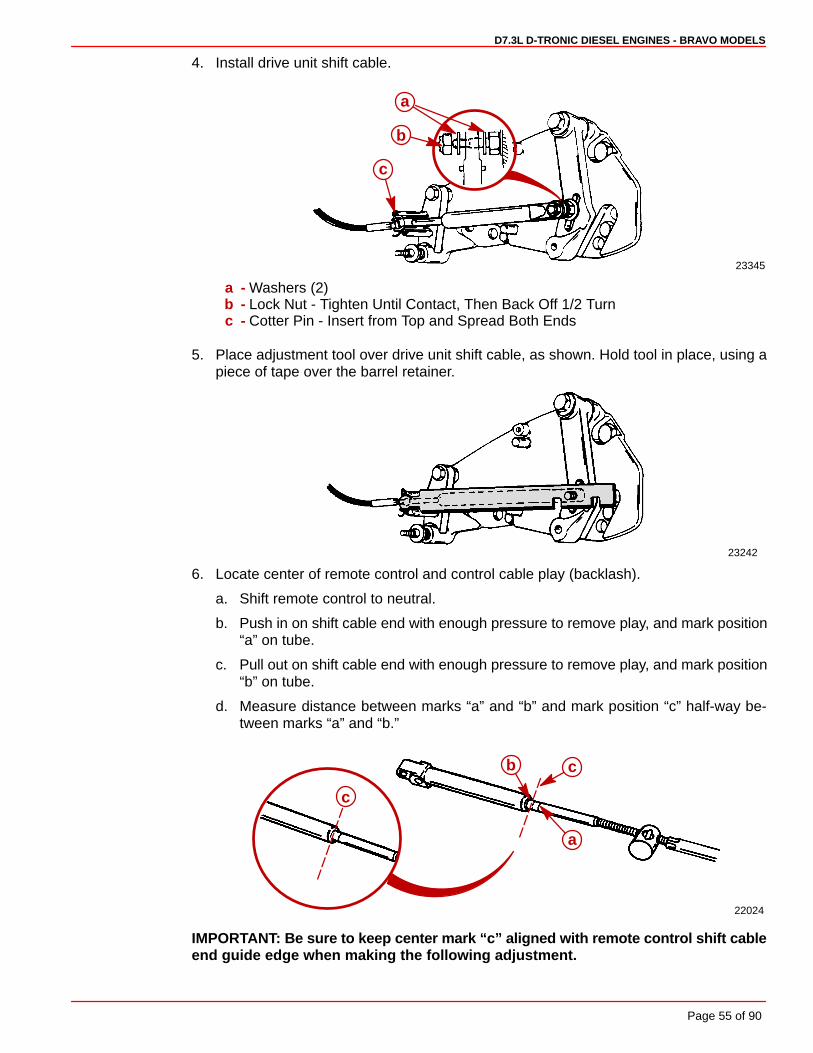
D7.3L D-TRONIC DIESEL ENGINES - BRAVO MODELS
Page 55 of 90
4. Install drive unit shift cable.
23345
a
b
c
a - Washers (2)b - Lock Nut - Tighten Until Contact, Then Back Off 1/2 Turnc - Cotter Pin - Insert from Top and Spread Both Ends
5. Place adjustment tool over drive unit shift cable, as shown. Hold tool in place, using apiece of tape over the barrel retainer.
23242
6. Locate center of remote control and control cable play (backlash).
a. Shift remote control to neutral.
b. Push in on shift cable end with enough pressure to remove play, and mark position“a” on tube.
c. Pull out on shift cable end with enough pressure to remove play, and mark position“b” on tube.
d. Measure distance between marks “a” and “b” and mark position “c” half-way be-tween marks “a” and “b.”
22024
a
cb
c
IMPORTANT: Be sure to keep center mark “c” aligned with remote control shift cableend guide edge when making the following adjustment.

D7.3L D-TRONIC DIESEL ENGINES - BRAVO MODELS
Page 56 of 90
7. Adjust remote control shift cable as follows:
a. Temporarily install shift cable end guide into shift lever, and insert anchor pin.
b. Adjust shift cable barrel so that hole in barrel centers with vertical centerline of stud.Ensure that backlash center mark is aligned with edge of control cable end guide.
CAUTIONDO NOT attempt to install or remove remote control shift cable barrel from stud,without first removing end guide anchor pin from shift lever, and removing cable.Attempting to bend shift cable to install or remove barrel, will place undue stresson cable end guide and shift lever, and damage to both could occur.
c. Remove shift cable end guide from shift lever, by removing anchor pin.
23242
a bc
e
d
a - Control Cable End Guideb - Anchor Pinc - Backlash Centerd - Control Cable Barrele - Stud
8. Install remote control shift cable.
23242
a
b
c
d
a - Lock Nut - Tighten Until Bottomed Outb - Washers - Both Sides of Barrelc - Anchor Pind - Cotter Pin (Not Visible) - Spread Both Ends
9. Remove adjustment tool.

D7.3L D-TRONIC DIESEL ENGINES - BRAVO MODELS
Page 57 of 90
10. Shift remote control lever into full forward position. Place end of adjustment tool in barrelretainer.
RH ROTATION BRAVO ONE, TWO, THREE AND BLACKHAWK MODEL: Rear slot in toolshould fit over shift lever stud.
LH ROTATION BRAVO ONE AND TWO: Forward slot in tool should fit over shift lever stud.
If slot does not fit over stud, loosen shift lever stud and slide stud either direction, until slotin tool fits over stud. When adjustment is correct, retighten stud.
23242
a
bc
d
RH Rotation Bravo One, Two, Three
23242
d
a
bc
LH Rotation Bravo One And Twoa - Adjustment Toolb - Barrel Retainerc - Shift Lever Studd - Shift Lever Adjustment Slot
11. Remove adjustment tool.
12. Lubricate shift cable pivot points with 30W oil.

D7.3L D-TRONIC DIESEL ENGINES - BRAVO MODELS
Page 58 of 90
Troubleshooting Shift ProblemsNOTE: The following information is provided to assist an installer in troubleshooting if hardshifting or chucking/racheting is encountered when shifting into forward gear.
1. When installing the control box in the side panel of the boat, make sure that the cableshave enough clearance to operate. This is necessary because the cables move up anddown when the shift handle is moved. If the control box is mounted too far back towardany fiberglass structure, the cables will be interfered with; this will cause very hard shift-ing.
NOTE: The control box housing can be rotated in 30° increments to improve cable routing.
74688
Proper Cable Bend
74689
Improper Cable Bend
2. Ensure that when the shift cable from the control box is led through the side gunnel ofthe hull, it does not have any extremely sharp bends in it as this will cause stiff shifting.
3. Before installing the shift cable into the control box, extend the stainless rod eye end ofthe cable and grease it with 2-4-C Marine Lubricant with Teflon. Move it back and forthto allow even distribution of the grease.
22005

D7.3L D-TRONIC DIESEL ENGINES - BRAVO MODELS
Page 59 of 90
4. Do not strap or clamp the control cables to any other cables or rigid structure within threefeet of the control box.
5. Be sure the cable is not permanently kinked.
6. Make sure there is proper clearance for cable movement when the control box isinstalled in the side panel. The cables must have room to move up and down when thecontrol handle is shifted into either forward or reverse.
7. Check to make sure that the engine was not set down on the intermediate shift cableduring installation, as this will crush the inner cable tubing and cause improper and / orstiff shifting.
8. DO NOT fasten the shift cable with straps or clamps to any other cable within five feetof the shift plate.
9. DO NOT fasten the shift cable to the transom with any type of plastic clips or fastenerswithin five feet of the shift plate.
10. DO NOT overtighten the throttle or shift cable attaching nuts at the engine end. Barreland cable end must be free to rotate on the mounting stud.

D7.3L D-TRONIC DIESEL ENGINES - BRAVO MODELS
Page 60 of 90
Throttle Cable Installation and Adjustment
IMPORTANT: When installing throttle cables, be sure that cables are routed in such a way as to avoidsharp bends and/or avoid contact with moving parts. DO NOT fasten any items to throttle cables.
1. Place remote control lever(s) in neutral/idle position.
2. Measure between the center of the Accelerator Position Sensor anchor stud to the holeson the cable barrel end bracket. Select the hole in the cable barrel end bracket thatis closest to the distance of 7-1/8 in. (181 mm) between studs.
76025
a
b c
d
e
a - Accelerator Position Sensor (APS/IVS)b - APS/IVS Anchor Studc - Cable Barrel End Bracketd - Cable Barrel Anchor Stude - 7-1/8 in. (181 mm)
3. Install cable end guide on throttle lever, then push cable barrel end lightly toward throttlelever end. (This will place a slight preload on shift cable to avoid slack in cable whenmoving remote control lever). Adjust barrel on throttle cable to align with stud in anchorbracket. Ensure hole in barrel positions cable as shown. Install cable and secure withhardware as shown.
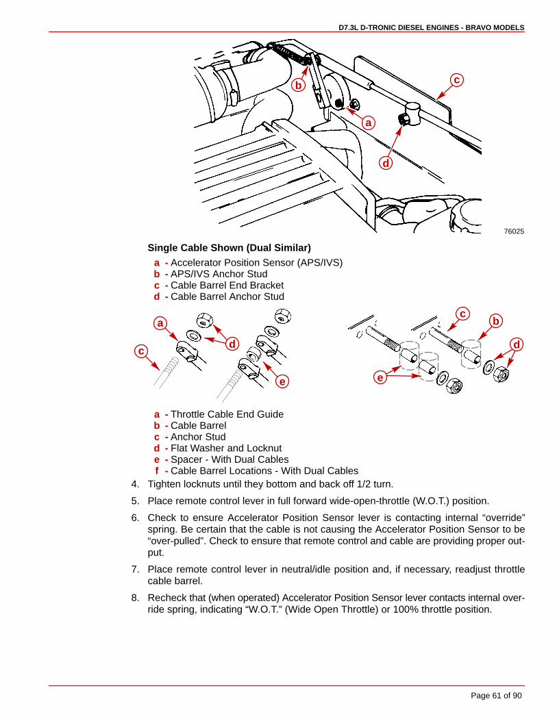
D7.3L D-TRONIC DIESEL ENGINES - BRAVO MODELS
Page 61 of 90
76025
a
b c
d
Single Cable Shown (Dual Similar)a - Accelerator Position Sensor (APS/IVS)b - APS/IVS Anchor Studc - Cable Barrel End Bracketd - Cable Barrel Anchor Stud
bc
dd
a
c
e e
a - Throttle Cable End Guideb - Cable Barrelc - Anchor Studd - Flat Washer and Locknute - Spacer - With Dual Cablesf - Cable Barrel Locations - With Dual Cables
4. Tighten locknuts until they bottom and back off 1/2 turn.
5. Place remote control lever in full forward wide-open-throttle (W.O.T.) position.
6. Check to ensure Accelerator Position Sensor lever is contacting internal “override”spring. Be certain that the cable is not causing the Accelerator Position Sensor to be“over-pulled”. Check to ensure that remote control and cable are providing proper out-put.
7. Place remote control lever in neutral/idle position and, if necessary, readjust throttlecable barrel.
8. Recheck that (when operated) Accelerator Position Sensor lever contacts internal over-ride spring, indicating “W.O.T.” (Wide Open Throttle) or 100% throttle position.

D7.3L D-TRONIC DIESEL ENGINES - BRAVO MODELS
Page 62 of 90
Sterndrive Unit Installation1. Remove trim cylinders’ support and dust cover from bell housing studs. Retain locknuts
and flat washers.
2. Remove cap and fill gear lube monitor.
75955
a
b
a - Gear Lube Monitorb - Cap
3. Push in on dribble valve until gear lube appears.
72471
a
a - Dribble Valve
4. Once gear lube appears, release dribble valve.
5. Fill monitor to FILL mark.
6. Replace monitor cap.
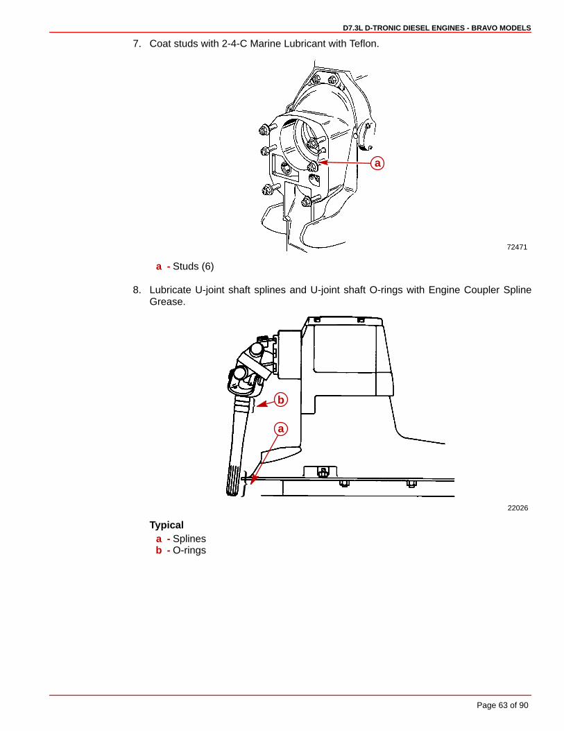
D7.3L D-TRONIC DIESEL ENGINES - BRAVO MODELS
Page 63 of 90
7. Coat studs with 2-4-C Marine Lubricant with Teflon.
72471
a
a - Studs (6)
8. Lubricate U-joint shaft splines and U-joint shaft O-rings with Engine Coupler SplineGrease.
22026
a
b
Typicala - Splinesb - O-rings

D7.3L D-TRONIC DIESEL ENGINES - BRAVO MODELS
Page 64 of 90
9. Check drive shaft bellows for cleanliness and absence of debris.
72472
a
a - Driveshaft Bellows
10. Lubricate O-ring seals with 2-4-C Marine Lubricant with Teflon.
72183a
a - O-Ring Seals
11. Pull out shift linkage as far as it moves. “Jaws” will open, as shown.
72460
a
a - Shift Linkage
IMPORTANT: As sterndrive is inserted into drive unit, entry of the bell housing shiftcable must be closely checked to make sure cable enters the “jaws” of shift linkageassembly in the sterndrive.
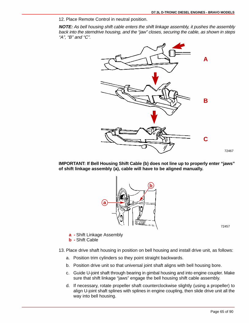
D7.3L D-TRONIC DIESEL ENGINES - BRAVO MODELS
Page 65 of 90
12. Place Remote Control in neutral position.
NOTE: As bell housing shift cable enters the shift linkage assembly, it pushes the assemblyback into the sterndrive housing, and the “jaw” closes, securing the cable, as shown in steps“A”, “B” and “C”.
72467
C
B
A
IMPORTANT: If Bell Housing Shift Cable (b) does not line up to properly enter “jaws”of shift linkage assembly (a), cable will have to be aligned manually.
72457
b
a
a - Shift Linkage Assemblyb - Shift Cable
13. Place drive shaft housing in position on bell housing and install drive unit, as follows:
a. Position trim cylinders so they point straight backwards.
b. Position drive unit so that universal joint shaft aligns with bell housing bore.
c. Guide U-joint shaft through bearing in gimbal housing and into engine coupler. Makesure that shift linkage “jaws” engage the bell housing shift cable assembly.
d. If necessary, rotate propeller shaft counterclockwise slightly (using a propeller) toalign U-joint shaft splines with splines in engine coupling, then slide drive unit all theway into bell housing.
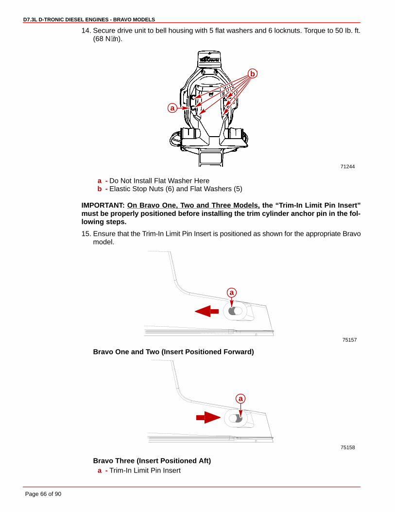
D7.3L D-TRONIC DIESEL ENGINES - BRAVO MODELS
Page 66 of 90
14. Secure drive unit to bell housing with 5 flat washers and 6 locknuts. Torque to 50 Ib. ft.(68 N⋅m).
71244
b
a
a - Do Not Install Flat Washer Hereb - Elastic Stop Nuts (6) and Flat Washers (5)
IMPORTANT: On Bravo One, Two and Three Models, the “Trim-In Limit Pin Insert”must be properly positioned before installing the trim cylinder anchor pin in the fol-lowing steps.
15. Ensure that the Trim-In Limit Pin Insert is positioned as shown for the appropriate Bravomodel.
75157
a
Bravo One and Two (Insert Positioned Forward)
75158
a
Bravo Three (Insert Positioned Aft)a - Trim-In Limit Pin Insert

D7.3L D-TRONIC DIESEL ENGINES - BRAVO MODELS
Page 67 of 90
IMPORTANT: The position of the Trim-In Limit Pin on the Bravo Three sterndrive unitshould only be changed after the boat has been properly tested. Refer to statementat the front of this manual entitled; “Bravo Three Notice: Trim-In Limit Pin”.
IMPORTANT: To aid in installing rubber bushings, use a water and soap solution. DONOT use oil or grease.
16. Install trim cylinders on aft end of drive unit with hardware as shown. Coat anchor pinthreads with 2-4-C Marine Lubricant with Teflon and tighten nuts until they bottom. Installplastic caps and tighten hand tight only.
71668 71669
a
bcc
c
d e
f
a - Aft Anchor Pinb - Large l.D. Flat Washers (2)c - Rubber Bushings (4)d - Small l.D. Flat Washers (2)e - Locknuts (2)f - Plastic Caps (2)
17. Place drive unit serial number decal as described in “General Information”.
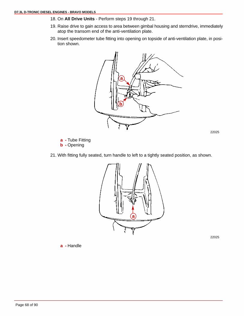
D7.3L D-TRONIC DIESEL ENGINES - BRAVO MODELS
Page 68 of 90
18. On All Drive Units - Perform steps 19 through 21.
19. Raise drive to gain access to area between gimbal housing and sterndrive, immediatelyatop the transom end of the anti-ventilation plate.
20. Insert speedometer tube fitting into opening on topside of anti-ventilation plate, in posi-tion shown.
22025
a
b
a - Tube Fittingb - Opening
21. With fitting fully seated, turn handle to left to a tightly seated position, as shown.
22025
a
a - Handle

D7.3L D-TRONIC DIESEL ENGINES - BRAVO MODELS
Page 69 of 90
Predelivery Preparation
NOTICE
Before starting Predelivery read “General Information” and “Installation Requirements”completely.
Battery ConnectionIMPORTANT: Engine electrical system is negative (–) ground.
1. Connect engine positive (+) battery cable (usually RED) to positive (+) battery terminal.
2. Connect engine negative (–) battery cable (usually BLACK) to negative (–) battery termi-nal.
3. Connect Power Trim pump BLACK (–) battery cable to negative (–) battery terminal andpump RED (+) battery cable to positive (+) battery terminal.
4. Make sure that all battery terminal connections are tight, then spray terminals with a bat-tery connection sealant to help retard corrosion.
Power Trim PumpIMPORTANT: Check oil level with sterndrive unit in the full DOWN/IN position.
IMPORTANT: Use Quicksilver Power Trim and Steering Fluid, or SAE 10W-30 or10W-40 engine oil in trim system.
1. Unscrew fill cap and remove caplug from fill neck and discard . Replace fill cap.
50630
a
a - Caplug
2. Raise and lower drive unit (to the full UP/OUT position) 6 to 10 times to purge air fromsystem. Check oil level visually, (with drive unit in the full DOWN/IN position). Oil levelshould be maintained at bottom lip of fill neck.

D7.3L D-TRONIC DIESEL ENGINES - BRAVO MODELS
Page 70 of 90
22031
a
a - Fill Neck
3. Check all trim line connection points for leaks. If fluid is visible at fittings, tighten fitting(s).Torque fitting(s) to 100-150 lb-in. (11-16 Nm).
Trim Position Sender Adjustment1. Loosen both trim position sender attaching screws.
71220
a
b
a - Attaching Screwsb - Trim Position Sender
CAUTIONDO NOT start engine in the following step or damage to drive unit and engine couldresult from lack of cooling water.
2. Turn ignition key to RUN position.
3. Trim drive unit to the full DOWN/IN position.
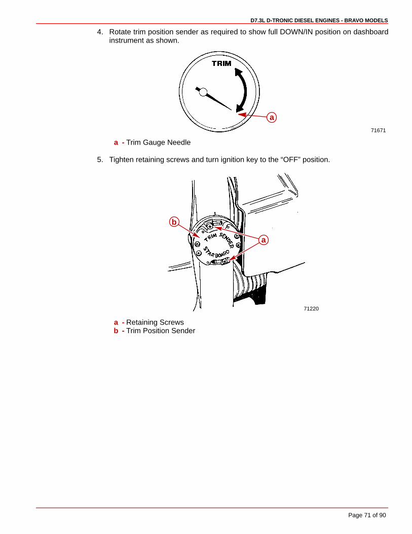
D7.3L D-TRONIC DIESEL ENGINES - BRAVO MODELS
Page 71 of 90
4. Rotate trim position sender as required to show full DOWN/IN position on dashboardinstrument as shown.
71671
a
a - Trim Gauge Needle
5. Tighten retaining screws and turn ignition key to the “OFF” position.
71220
a
b
a - Retaining Screwsb - Trim Position Sender
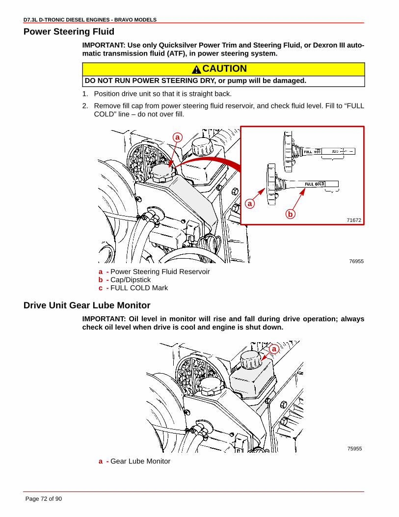
D7.3L D-TRONIC DIESEL ENGINES - BRAVO MODELS
Page 72 of 90
Power Steering FluidIMPORTANT: Use only Quicksilver Power Trim and Steering Fluid, or Dexron III auto-matic transmission fluid (ATF), in power steering system.
CAUTIONDO NOT RUN POWER STEERING DRY, or pump will be damaged.
1. Position drive unit so that it is straight back.
2. Remove fill cap from power steering fluid reservoir, and check fluid level. Fill to “FULLCOLD” line – do not over fill.
76955
71672
ab
a
a - Power Steering Fluid Reservoirb - Cap/Dipstickc - FULL COLD Mark
Drive Unit Gear Lube MonitorIMPORTANT: Oil level in monitor will rise and fall during drive operation; alwayscheck oil level when drive is cool and engine is shut down.
75955
a
a - Gear Lube Monitor

D7.3L D-TRONIC DIESEL ENGINES - BRAVO MODELS
Page 73 of 90
1. With drive in full down position, remove oil vent screw.
CAUTIONFailure to fill drive unit to level of vent hole will result in a low drive oil level. Gearlube monitor only MAINTAINS drive oil level and will not correct an improperly filleddrive unit.
2. Fill gear lube monitor with Quicksilver Gear Lube. When oil starts to run out the oil venthole, reinsert oil vent screw, and sealing washer, and tighten securely.
3. Fill monitor to “FILL” mark. Lubricate O-ring in cap with sterndrive oil, to insure ease ofinstalling and removing cap, and install cap. Do not over-tighten cap.
4. Recheck oil level after first use.
70121
a
b
a - Oil Vent Screw and Sealing Washerb - Oil Vent Hole
Propeller Installation
BRAVO ONE AND TWO
IMPORTANT: Correct rotation propeller MUST match direction of rotation of propellershaft.
WARNINGBe sure that remote control is in neutral position and ignition key is removed fromswitch prior to installing propeller.
WARNINGPlace a block of wood between the anti-ventilation plate and propeller to protecthands from propeller blades and to prevent propeller from turning when tighteningpropeller nut.
1. To aid in future removal of the propeller, liberally coat propeller shaft splines with oneof the following Quicksilver lubricants.
• Special Lubricant 101
• 2-4-C Marine Lubricant with Teflon
IMPORTANT: Installation is correct when at least 2 threads of propeller shaft are ex-posed through propeller nut after torquing it.
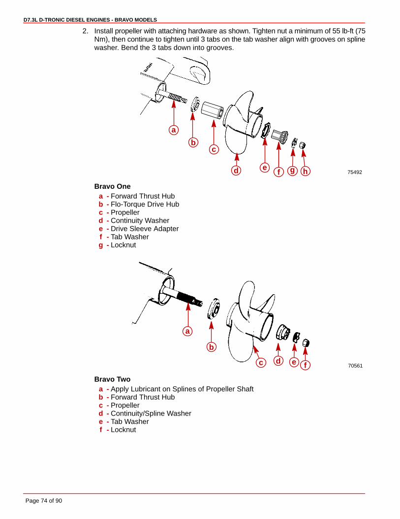
D7.3L D-TRONIC DIESEL ENGINES - BRAVO MODELS
Page 74 of 90
2. Install propeller with attaching hardware as shown. Tighten nut a minimum of 55 lb-ft (75Nm), then continue to tighten until 3 tabs on the tab washer align with grooves on splinewasher. Bend the 3 tabs down into grooves.
75492
a
bc
f he gd
Bravo Onea - Forward Thrust Hubb - Flo-Torque Drive Hubc - Propellerd - Continuity Washere - Drive Sleeve Adapterf - Tab Washerg - Locknut
70561
a
b
c d e f
Bravo Twoa - Apply Lubricant on Splines of Propeller Shaftb - Forward Thrust Hubc - Propellerd - Continuity/Spline Washere - Tab Washerf - Locknut

D7.3L D-TRONIC DIESEL ENGINES - BRAVO MODELS
Page 75 of 90
BRAVO THREE
IMPORTANT: Correct rotation propeller MUST match direction of rotation of propellershaft.
WARNINGBe sure that remote control is in neutral position and ignition key is removed fromswitch prior to installing propeller.
WARNINGPlace a block of wood between the anti-ventilation plate and propeller to protecthands from propeller blades and to prevent propeller from turning when tighteningpropeller nut.
1. To aid in future removal of the propeller, liberally coat the propeller shaft splines with oneof the following Quicksilver lubricants.
• Special Lubricant 101
• 2-4-C Marine Lubricant with Teflon
2. Install propellers with attaching hardware as follows:
a. Slide forward thrust hub onto propeller shaft, with tapered side toward propeller hub.
b. Align splines and place front propeller on propeller shaft.
c. Install front propeller locknut. Torque to 100 lb-ft (136 N⋅m).
d. Slide aft thrust hub onto propeller shaft with tapered side toward propeller hub.
e. Align splines and install aft propeller.
f. Install propeller locknut. Torque to 60 lb-ft (81 N⋅m).
72239bcde
f a
Bravo Threea - Rear Propeller Locknutb - Rear Propellerc - Rear Propeller Thrust Hubd - Front Propeller Locknute - Front Propellerf - Front Propeller Thrust Hub
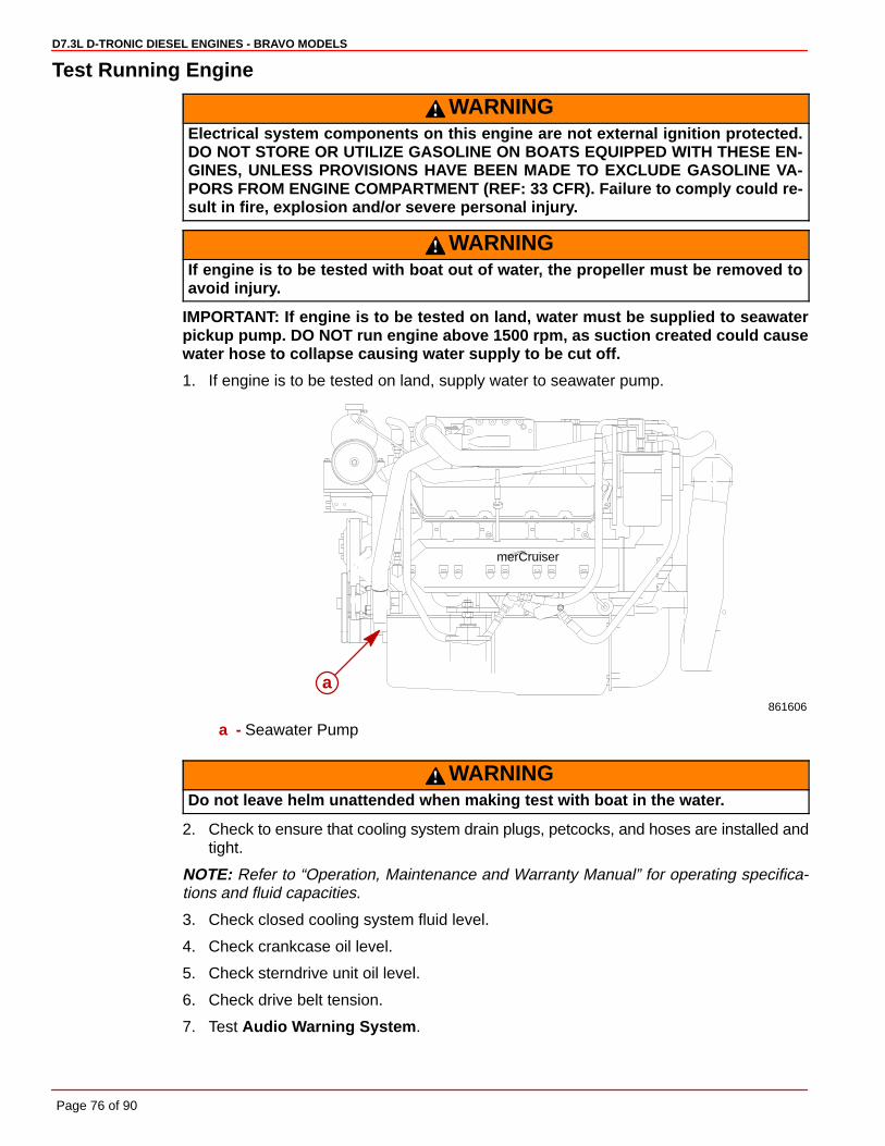
D7.3L D-TRONIC DIESEL ENGINES - BRAVO MODELS
Page 76 of 90
Test Running Engine
WARNINGElectrical system components on this engine are not external ignition protected.DO NOT STORE OR UTILIZE GASOLINE ON BOATS EQUIPPED WITH THESE EN-GINES, UNLESS PROVISIONS HAVE BEEN MADE TO EXCLUDE GASOLINE VA-PORS FROM ENGINE COMPARTMENT (REF: 33 CFR). Failure to comply could re-sult in fire, explosion and/or severe personal injury.
WARNINGIf engine is to be tested with boat out of water, the propeller must be removed toavoid injury.
IMPORTANT: If engine is to be tested on land, water must be supplied to seawaterpickup pump. DO NOT run engine above 1500 rpm, as suction created could causewater hose to collapse causing water supply to be cut off.
1. If engine is to be tested on land, supply water to seawater pump.
861606
merCruiser
a
a - Seawater Pump
WARNINGDo not leave helm unattended when making test with boat in the water.
2. Check to ensure that cooling system drain plugs, petcocks, and hoses are installed andtight.
NOTE: Refer to “Operation, Maintenance and Warranty Manual” for operating specifica-tions and fluid capacities.
3. Check closed cooling system fluid level.
4. Check crankcase oil level.
5. Check sterndrive unit oil level.
6. Check drive belt tension.
7. Test Audio Warning System .
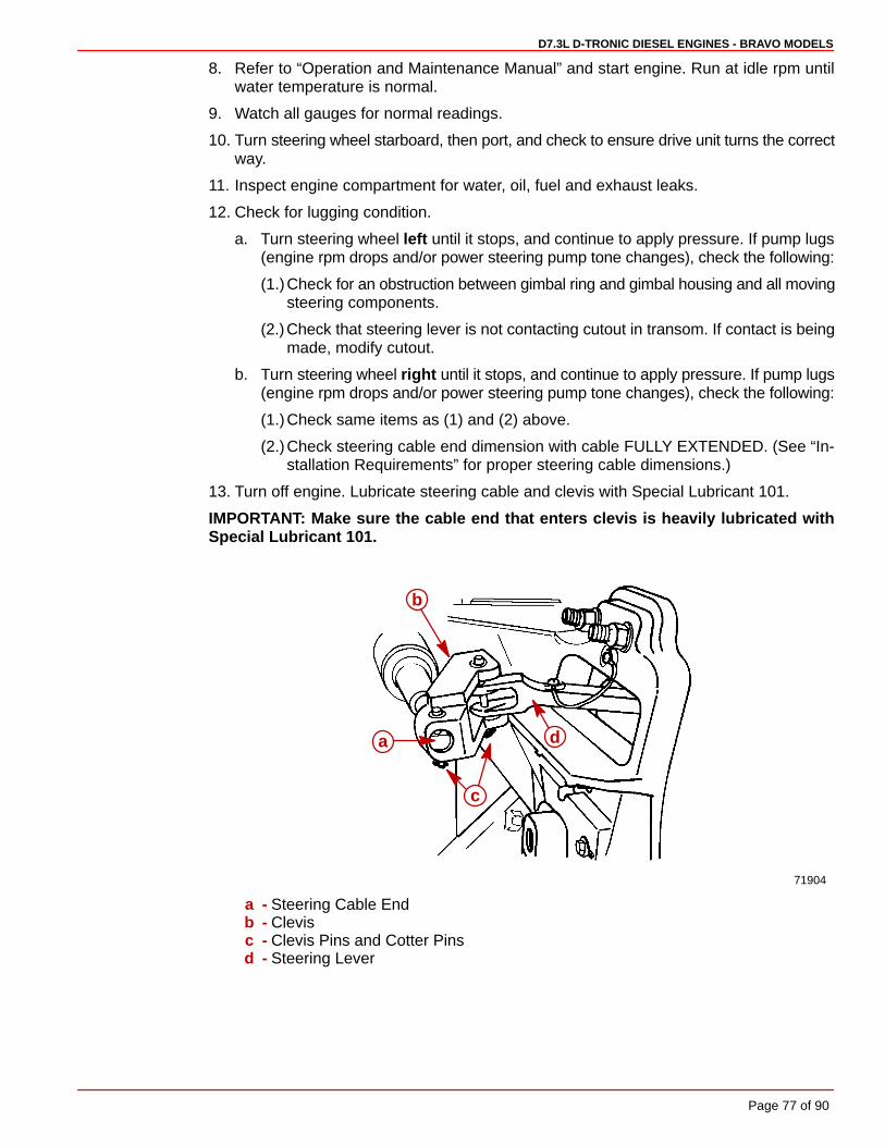
D7.3L D-TRONIC DIESEL ENGINES - BRAVO MODELS
Page 77 of 90
8. Refer to “Operation and Maintenance Manual” and start engine. Run at idle rpm untilwater temperature is normal.
9. Watch all gauges for normal readings.
10. Turn steering wheel starboard, then port, and check to ensure drive unit turns the correctway.
11. Inspect engine compartment for water, oil, fuel and exhaust leaks.
12. Check for lugging condition.
a. Turn steering wheel left until it stops, and continue to apply pressure. If pump lugs(engine rpm drops and/or power steering pump tone changes), check the following:
(1.)Check for an obstruction between gimbal ring and gimbal housing and all movingsteering components.
(2.)Check that steering lever is not contacting cutout in transom. If contact is beingmade, modify cutout.
b. Turn steering wheel right until it stops, and continue to apply pressure. If pump lugs(engine rpm drops and/or power steering pump tone changes), check the following:
(1.)Check same items as (1) and (2) above.
(2.)Check steering cable end dimension with cable FULLY EXTENDED. (See “In-stallation Requirements” for proper steering cable dimensions.)
13. Turn off engine. Lubricate steering cable and clevis with Special Lubricant 101.
IMPORTANT: Make sure the cable end that enters clevis is heavily lubricated withSpecial Lubricant 101.
71904
d
c
a
b
a - Steering Cable Endb - Clevisc - Clevis Pins and Cotter Pinsd - Steering Lever

D7.3L D-TRONIC DIESEL ENGINES - BRAVO MODELS
Page 78 of 90
14. Restart engine and observe drive unit. If drive unit creeps, an external tension may existon steering cable. Ensure that there is nothing attached to steering cable casing. Cablemust be free to move when actuated.
15. Check power steering pump fluid level:
a. Position drive unit so it is straight back. Turn off engine.
b. Remove cap/dipstick from power steering fluid reservoir. Check fluid level and addas necessary. Do not overfill.
76955
71672
aa
bc
a - Power Steering Fluid Reservoirb - Cap/Dipstickc - FULL COLD Mark
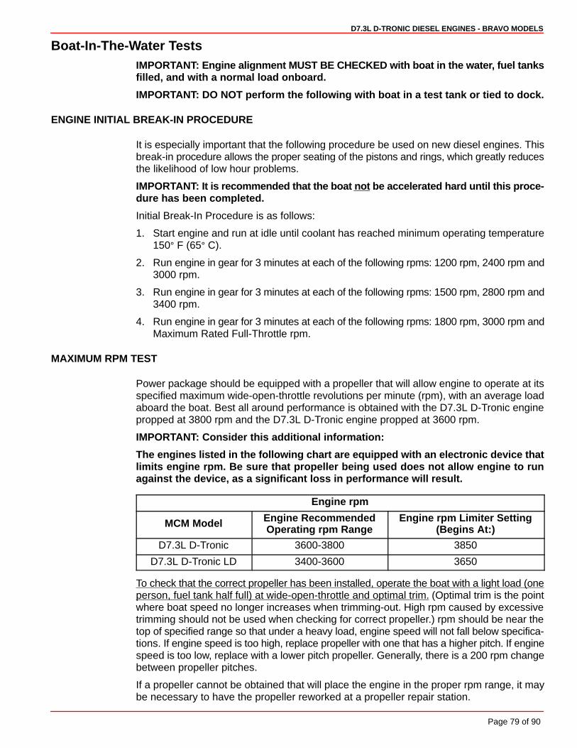
D7.3L D-TRONIC DIESEL ENGINES - BRAVO MODELS
Page 79 of 90
Boat-In-The-Water TestsIMPORTANT: Engine alignment MUST BE CHECKED with boat in the water, fuel tanksfilled, and with a normal load onboard.
IMPORTANT: DO NOT perform the following with boat in a test tank or tied to dock.
ENGINE INITIAL BREAK-IN PROCEDURE
It is especially important that the following procedure be used on new diesel engines. Thisbreak-in procedure allows the proper seating of the pistons and rings, which greatly reducesthe likelihood of low hour problems.
IMPORTANT: It is recommended that the boat not be accelerated hard until this proce-dure has been completed.
Initial Break-In Procedure is as follows:
1. Start engine and run at idle until coolant has reached minimum operating temperature150° F (65° C).
2. Run engine in gear for 3 minutes at each of the following rpms: 1200 rpm, 2400 rpm and3000 rpm.
3. Run engine in gear for 3 minutes at each of the following rpms: 1500 rpm, 2800 rpm and3400 rpm.
4. Run engine in gear for 3 minutes at each of the following rpms: 1800 rpm, 3000 rpm andMaximum Rated Full-Throttle rpm.
MAXIMUM RPM TEST
Power package should be equipped with a propeller that will allow engine to operate at itsspecified maximum wide-open-throttle revolutions per minute (rpm), with an average loadaboard the boat. Best all around performance is obtained with the D7.3L D-Tronic enginepropped at 3800 rpm and the D7.3L D-Tronic engine propped at 3600 rpm.
IMPORTANT: Consider this additional information:
The engines listed in the following chart are equipped with an electronic device thatlimits engine rpm. Be sure that propeller being used does not allow engine to runagainst the device, as a significant loss in performance will result.
Engine rpm
MCM Model Engine RecommendedOperating rpm Range
Engine rpm Limiter Setting(Begins At:)
D7.3L D-Tronic 3600-3800 3850
D7.3L D-Tronic LD 3400-3600 3650
To check that the correct propeller has been installed, operate the boat with a light load (oneperson, fuel tank half full) at wide-open-throttle and optimal trim. (Optimal trim is the pointwhere boat speed no longer increases when trimming-out. High rpm caused by excessivetrimming should not be used when checking for correct propeller.) rpm should be near thetop of specified range so that under a heavy load, engine speed will not fall below specifica-tions. If engine speed is too high, replace propeller with one that has a higher pitch. If enginespeed is too low, replace with a lower pitch propeller. Generally, there is a 200 rpm changebetween propeller pitches.
If a propeller cannot be obtained that will place the engine in the proper rpm range, it maybe necessary to have the propeller reworked at a propeller repair station.

D7.3L D-TRONIC DIESEL ENGINES - BRAVO MODELS
Page 80 of 90
IMPORTANT: To run engine at maximum rpm before the Engine 20-Hour Break-In Pe-riod is complete, follow this procedure only after the Engine Initial Break-in Proce-dure has been completed:
1. Complete Engine Initial Break-In Procedures if not already accomplished.
2. Start engine and run at idle rpm until normal operating temperature is reached.
3. Run boat up on plane.
4. Advance engine rpm (in 200 rpm increments) until engine reaches its maximum ratedrpm. If maximum rated rpm is not possible or engine runs against governor refer to pre-ceding information for correct propeller selection.
IMPORTANT: Do not run at maximum rpm for more than 2 minutes.
After Running Engine
CAUTIONIf Power Package will not be used for an extended period of time, or will be exposedto freezing temperatures, drain water from seawater cooling system, as explainedin owner’s “Operation, Maintenance and Warranty Manual.” Water MUST BEdrained to prevent corrosion and freeze damage to engine.
1. If Power Package will not be used for an extended period of time, or will be exposed tofreezing temperatures, drain water from seawater cooling system.
CAUTIONSterndrive unit should be stored in full “down” position. Universal Joint bellowsmay develop a “set” if unit is stored in raised position and may fail when unit is re-turned to service.
2. If power package is to be stored, position sterndrive unit full “DOWN/IN”.
D7.3L D-TRONIC DIESEL ENGINES - BRAVO MODELS
Page 81 of 90
Cold Weather or Extended Storage Draining Instructions
CAUTIONIf Power Package will not be used for an extended period of time or will be exposedto freezing temperatures, drain water from seawater section of cooling system.Water MUST BE drained to prevent corrosion and freeze damage to engine.
CAUTIONIf boat is to remain in the water, seacock, if so equipped, must remain closed untilengine is to be restarted to prevent water from flowing back into seawater coolingsystem. If boat is not fitted with a seacock, water inlet hose must be disconnectedand plugged to prevent water from flowing into cooling system and/or boat. As aprecautionary measure, attach a tag to the ignition switch or steering wheel with thewarning that the seacock must be opened or the water inlet hose reconnected priorto starting the engine.
IMPORTANT: Mercury MerCruiser recommends that propylene glycol antifreeze (anontoxic and environmentally safe) antifreeze be used in seawater section of thecooling system for cold weather or extended storage. Make sure that the propyleneglycol antifreeze contains a rust inhibitor and is recommended for use in marine en-gines. Be certain to follow the propylene glycol manufacturer’s recommendations.
IMPORTANT: Observe the following information to ensure complete draining of cool-ing system:
• Engine must be as level as possible.
• A wire should be repeatedly inserted into all drain holes to ensure there are noobstructions in passages.
IMPORTANT: Drain seawater section of closed cooling system only.
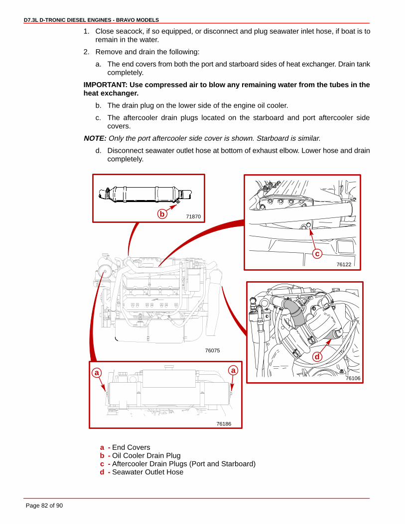
D7.3L D-TRONIC DIESEL ENGINES - BRAVO MODELS
Page 82 of 90
1. Close seacock, if so equipped, or disconnect and plug seawater inlet hose, if boat is toremain in the water.
2. Remove and drain the following:
a. The end covers from both the port and starboard sides of heat exchanger. Drain tankcompletely.
IMPORTANT: Use compressed air to blow any remaining water from the tubes in theheat exchanger.
b. The drain plug on the lower side of the engine oil cooler.
c. The aftercooler drain plugs located on the starboard and port aftercooler sidecovers.
NOTE: Only the port aftercooler side cover is shown. Starboard is similar.
d. Disconnect seawater outlet hose at bottom of exhaust elbow. Lower hose and draincompletely.
76122
71870
76186
aa
b
c
76075
76106
d
a - End Coversb - Oil Cooler Drain Plugc - Aftercooler Drain Plugs (Port and Starboard)d - Seawater Outlet Hose

D7.3L D-TRONIC DIESEL ENGINES - BRAVO MODELS
Page 83 of 90
3. Repeatedly clean out drain holes using a stiff piece of wire. Do this until entire systemis drained.
4. Remove seawater pump outlet hose from top of seawater pump and drain.
76107
b
a
a - Seawater Pumpb - Outlet Hose
CAUTIONAvoid water entering boat. Do not unplug or disconnect seawater inlet hose unlessa seacock is present and it is closed.
5. Remove hose(s) at seawater strainer and drain hose(s) completely. Remove drain plugand empty seawater strainer. Reconnect hoses. Tighten hose clamps securely. Installdrain plug. Tighten securely.
71362
a
b
c c
a - Seawater Strainerb - Drain Plugc - Hose
6. After seawater section of cooling system has been drained completely, coat threads ofdrain plugs with Perfect Seal and reinstall. Tighten securely. Connect hose to seawaterpump outlet (top). Tighten hose clamps securely. Replace end cover gaskets and seals,if worn or deteriorated. Install end cover assemblies on the heat exchanger. Torque theend covers to 120-132 lb-in. (14-15 Nm).

73962
BLK = BLACKBLU = BLUEBRN = BROWNGRY = GRAYGRN = GREENORN = ORANGEPNK = PINKPUR = PURPLERED = REDTAN = TAN
WHT = WHITEYEL = YELLOW
LT OR LIT = LIGHTDRK = DARK
b
c
d
e
f
g
h
a
D7.3L D-TRONIC DIESEL ENGINES - BRAVO MODELS
Page 84 of 90
Power Trim System Wiring Diagram
a - 20 Amp Fuseb - Ground Bolt (Floor Mount)c - “UP” Solenoidd - 110 Amp Fusee - “DOWN” Solenoidf - Trailer Switchg - Neutral Switch to Instrument Wiring Harnessh - Trim Limit Switch

BLK = BLACKBLU = BLUEBRN = BROWNGRY= GRAYGRN= GREENORN= ORANGEPNK = PINKPUR = PURPLERED = REDTAN = TANWHT= WHITEYEL = YELLOWLT OR LIT=LIGHTDRK = DARK
73596
a
b
c
D7.3L D-TRONIC DIESEL ENGINES - BRAVO MODELS
Page 85 of 90
MerCathode System Wiring Diagram
a - Controllerb - 20 Amp Fusec - Electrode
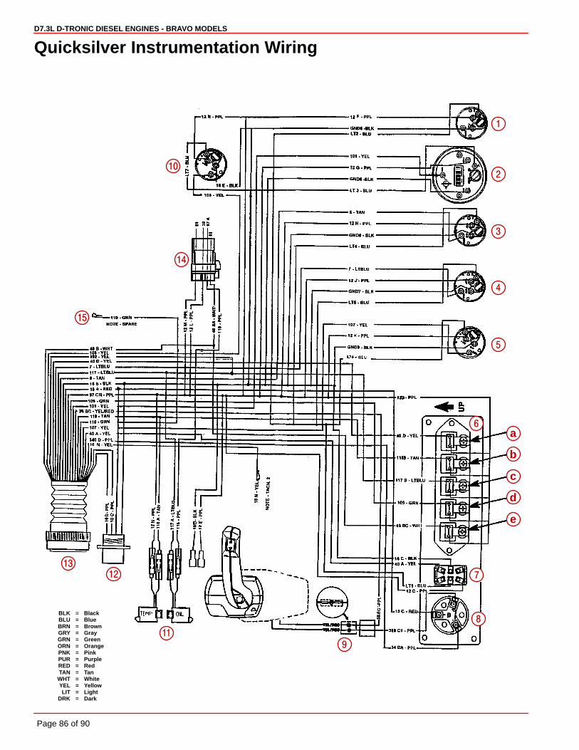
BLK = BlackBLU = BlueBRN = BrownGRY = GrayGRN = GreenORN = OrangePNK = PinkPUR = PurpleRED = RedTAN = Tan
WHT = WhiteYEL = YellowLIT = Light
DRK = Dark
15
1
5
4
3
2
a
b
c
d
e
7
8
9
10
11
12
13
14
6
D7.3L D-TRONIC DIESEL ENGINES - BRAVO MODELS
Page 86 of 90
Quicksilver Instrumentation Wiring
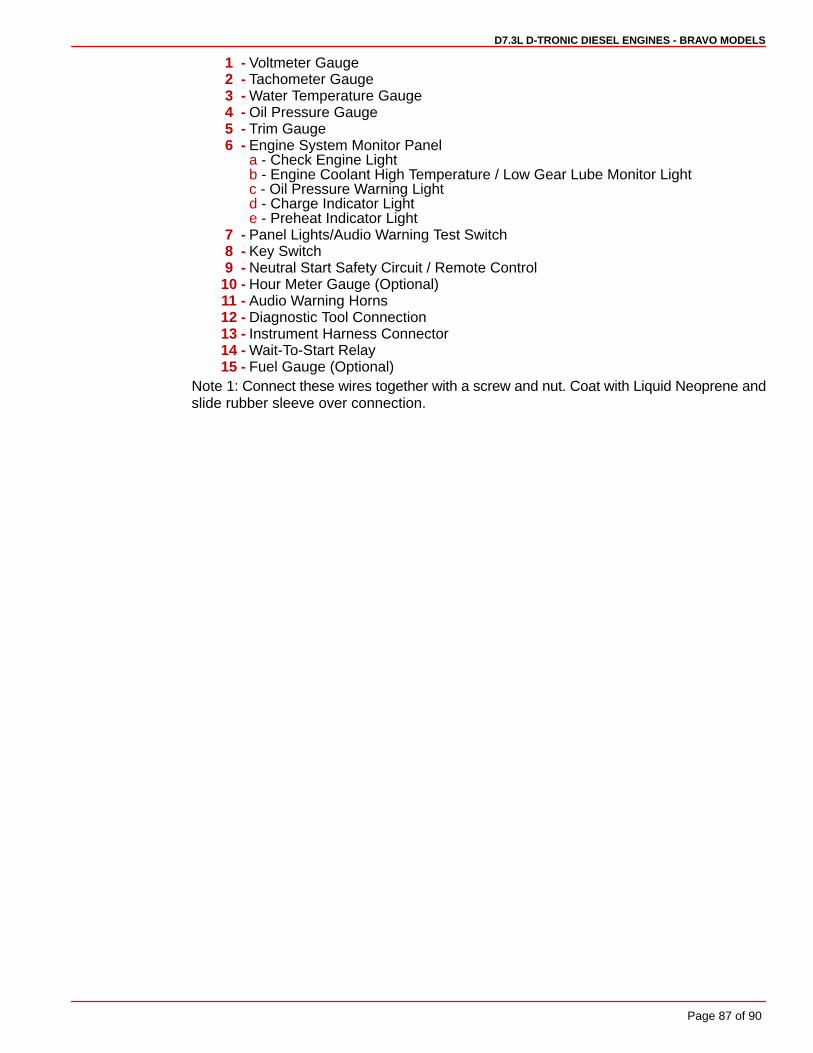
D7.3L D-TRONIC DIESEL ENGINES - BRAVO MODELS
Page 87 of 90
1 - Voltmeter Gauge2 - Tachometer Gauge3 - Water Temperature Gauge4 - Oil Pressure Gauge5 - Trim Gauge6 - Engine System Monitor Panel
a - Check Engine Lightb - Engine Coolant High Temperature / Low Gear Lube Monitor Lightc - Oil Pressure Warning Lightd - Charge Indicator Lighte - Preheat Indicator Light
7 - Panel Lights/Audio Warning Test Switch8 - Key Switch9 - Neutral Start Safety Circuit / Remote Control
10 - Hour Meter Gauge (Optional)11 - Audio Warning Horns12 - Diagnostic Tool Connection13 - Instrument Harness Connector14 - Wait-To-Start Relay15 - Fuel Gauge (Optional)
Note 1: Connect these wires together with a screw and nut. Coat with Liquid Neoprene andslide rubber sleeve over connection.
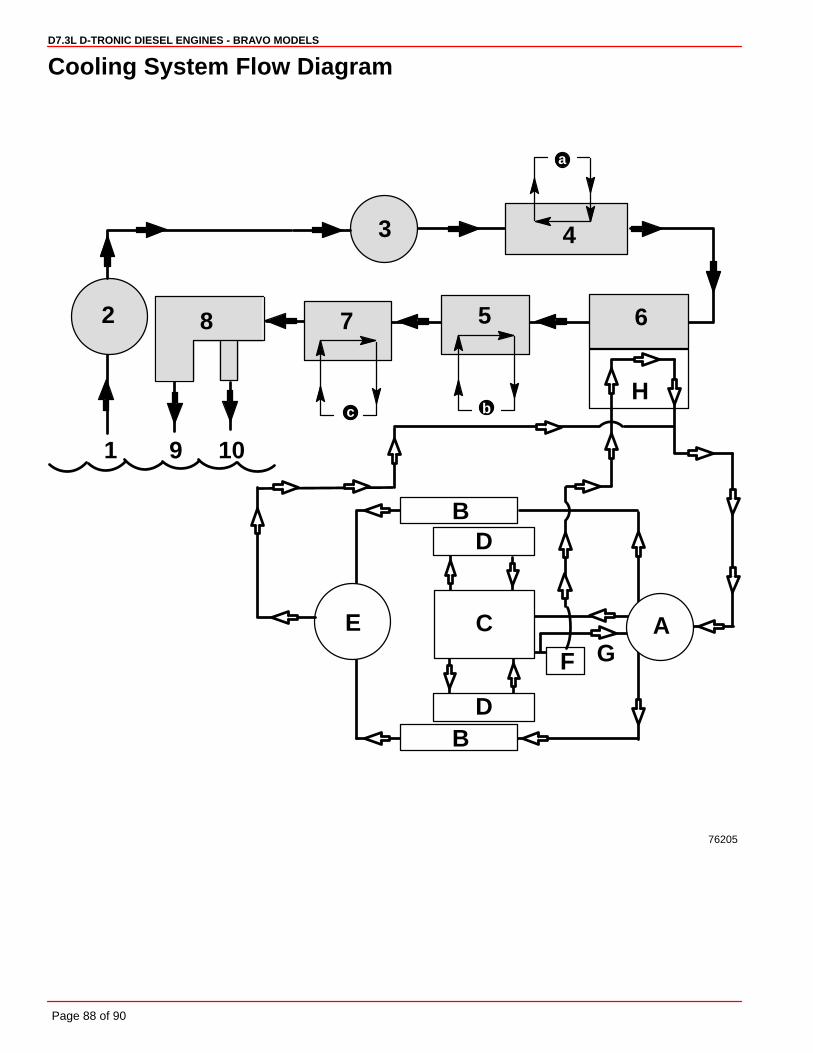
D7.3L D-TRONIC DIESEL ENGINES - BRAVO MODELS
Page 88 of 90
Cooling System Flow Diagram
76205
1
2
3 4
8
9 10
7
c
a
A
B
C
F G
B
D
D
E
H
5
b
6

D7.3L D-TRONIC DIESEL ENGINES - BRAVO MODELS
Page 89 of 90
SEAWATER COOLING CIRCUIT (RAW WATER)
1 - Seawater Inlet 2 - Seawater Strainer3 - Seawater Pump4 - Aftercooler5 - Engine Oil Cooler6 - Heat Exchanger (Seawater Circuit)7 - Power Steering Fluid Cooler8 - Exhaust Pipe Water Jacket9 - Seawater Outlet (Exhaust)10- Seawater Outlet (Thru-Transom)
CLOSED COOLING CIRCUIT (FRESH WATER/COOLANT)
A- Circulating Pump - Closed CoolantB- Exhaust ManifoldsC- Engine CrankcaseD- Cylinder HeadsE- TurbochargerF - ThermostatG- BypassH- Heat Exchanger (Closed Cooling Circuit)
FLOW OF :a ENGINE AIRb ENGINE OILc POWER STEERING FLUID

D7.3L D-TRONIC DIESEL ENGINES - BRAVO MODELS
Page 90 of 90
Predelivery InspectionNot Check/Applicable Adjust
Not Check/Applicable Adjust
CHECK BEFORE RUNNING ON THE WATER TESTDrain plug in and petcocks Engine alignment (Inboards only)closed
Seawater inlet valve open Starter neutral safety switch operation
Engine mounts tightWater pump operation
Engine alignmentInstruments(s) operation
Drive unit fasteners torquedFuel leaks
Power trim cylinders fastenerstight Oil leaks
Battery fully charged and securedWater leaks
All electrical connections tightExhaust leaks
Exhaust system hose clampstight Ignition timing
All fuel connections tightIdle RPM, within specifications
Correct rotation propeller(installed and torqued)
Throttle, shift and steering system Forward - Neutral - Reversefasteners tightened properly gear operation
Throttle plates open and close Steering operation throughoutcompletely range
Crankcase oil level Acceleration from idle rpm
Power trim oil level WOT RPM withinspecifications (in forward gear)
Stern drive unit oil levelPower trim operation
Power steering fluid levelTrim tab adjustment
Closed cooling levelBoat handling
Transmission fluid levelAFTER ON WATER TEST
Alternator belt tensionPropeller nut torque
Seawater pickup pump belttension
Fuel, oil, coolant, water and fluidPower steering pump belt tension leaks
Audio warning system operation Oil and fluid levels
Apply Quicksilver Corrosion Guard toengine package