quickstart “basic” guidelines for model 9200 “full … · 2019. 12. 11. · master link o...
TRANSCRIPT
Anti-Grounding Plate
TIME
DELAY
EXITLO
OP
LMT
REVERSE
LOO
P
REV SENSEO
PENREV SENSECLO
SE
1
ON
234 1
ON
2345678
NCNO
P8P7
P6
4404-010
20 19 18 17 16 15 14 13 12 11 10 9 8 7 6 5 4 3 2 1
94109410
1 2 5 6 11 13A
13B
13E
25 16 17
U
L1 L2/N B- B+
V W PE PE
Mode
EPM
SpeedController
1.0 PE
SCM seriesbasic I/O control
115 VAC Convenience Outlets
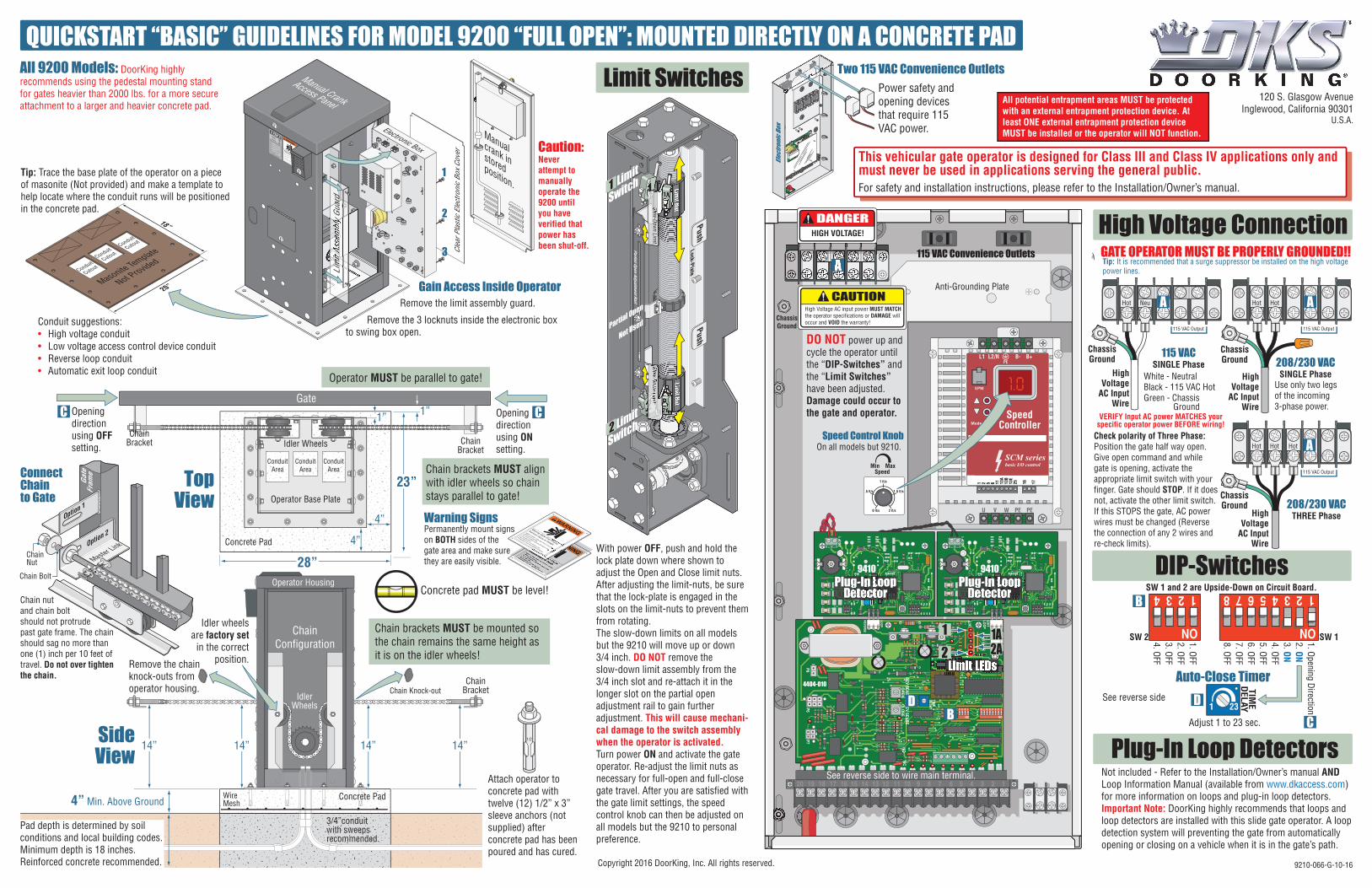
DO NOT power up and cycle the operator until the “DIP-Switches” and the “Limit Switches” have been adjusted. Damage could occur to the gate and operator.
TTTTTTTTT
Openingdirectionusing OFFsetting.
Openingdirectionusing ONsetting.
EXITLO
OPLM
T
REVERSE
LOO
P
REV SENSECLO
SE
P8P7
P6
4404-010
1
2
4
3
1
2
4
3
1
2
4
3
Elect
roni
c Box
Power safety and opening devices that require 115 VAC power.
Two 115 VAC Convenience Outlets
Clea
r Pla
stic
Ele
ctro
nic
Box
Cove
r
This vehicular gate operator is designed for Class III and Class IV applications only and must never be used in applications serving the general public.For safety and installation instructions, please refer to the Installation/Owner’s manual.
Copyright 2016 DoorKing, Inc. All rights reserved. 9210-066-G-10-16
Plug-In Loop DetectorsNot included - Refer to the Installation/Owner’s manual AND Loop Information Manual (available from www.dkaccess.com) for more information on loops and plug-in loop detectors.Important Note: DoorKing highly recommends that loops and loop detectors are installed with this slide gate operator. A loop detection system will preventing the gate from automatically opening or closing on a vehicle when it is in the gate’s path.
High Voltage ConnectionTip: It is recommended that a surge suppressor be installed on the high voltage power lines.
GATE OPERATOR MUST BE PROPERLY GROUNDED!!
DIP-Switches
Limit Switches1. Opening Direction2. ON3. ON4. OFF5. OFF6. OFF7. OFF8. OFF
1. OFF2. OFF3. OFF4. OFF
Auto-Close Timer
ChassisGround
DANGERHIGH VOLTAGE!
1
ON
23456781
ON
234SW 1 and 2 are Upside-Down on Circuit Board.
1 23
TIME
DELAY
A
B
DC
C C
BD
1 ft/s
.5 ft/s
0 ft/s 2 ft/s
1.5 ft/s
Limit LEDs
Plug-In LoopDetector
Plug-In LoopDetector
Min MaxSpeed
PushPush
Lock-Plate
Limit Nut
Limit Nut
Slow-Dow
n Limit
Slow-Dow
n Limit
1A
2A
Partial Open
Not Used
12 2A
1A
Adjust 1 to 23 sec.
See reverse side
See reverse side to wire main terminal.
1 Limit
Switch
2 Limit
SwitchCheck polarity of Three Phase: Position the gate half way open. Give open command and while gate is opening, activate the appropriate limit switch with your finger. Gate should STOP. If it does not, activate the other limit switch. If this STOPS the gate, AC power wires must be changed (Reverse the connection of any 2 wires and re-check limits).
Partial Open Adjustment Rail
208/230 VACTHREE Phase
ChassisGround
HighVoltage
AC InputWire
Hot
115 VAC Output
Hot Hot
208/230 VACSINGLE Phase
ChassisGround
HighVoltage
AC InputWire
Hot
115 VAC Output
Hot
Use only two legs of the incoming 3-phase power.
ChassisGround
HighVoltage
AC InputWire
Hot
115 VAC Output
Neu
115 VACSINGLE Phase
White - NeutralBlack - 115 VAC HotGreen - Chassis Ground
SW 1SW 2
AA
A
IdlerWheels
Operator Housing
14”14” 14” 14”
Gate
Operator MUST be parallel to gate!
Chain brackets MUST align with idler wheels so chain stays parallel to gate!
Chain brackets MUST be mounted so the chain remains the same height as it is on the idler wheels!
ChainBracket Chain
Bracket
ChainBracket
Idler Wheels
Operator Base Plate
ChainConfiguration
Concrete Pad
Concrete Pad
4” Min. Above Ground
Remove the limit assembly guard.
Remove the 3 locknuts inside the electronic box to swing box open.
WARNING
MOVING GATE CAN CAUSE
Operate gate only when gate area is in sight
and free of people and obstructions.
Do not allow children to play in gate area
or operate gate.Do not stand in gate path or walk through
path while gate is moving.
Read owner’s manual and safety instructions.
SERIOUS INJURY OR DEATH
CLASS
CERTIFIED TO
CAN/CSA C22.2 NO. 247
CONFORMS TO
ANSI/UL-325
VEHICULAR GATE OPERATORHP
53382
MODELSERIALVOLTS
PHASE
AMPS
60 Hz
MAX GATE LOADDoorKing, Inc., Inglewood, CA
Lim
it As
sem
bly
Guar
d
Electronic Box
Tip: Trace the base plate of the operator on a piece of masonite (Not provided) and make a template to help locate where the conduit runs will be positioned in the concrete pad.
Pad depth is determined by soil conditions and local building codes. Minimum depth is 18 inches. Reinforced concrete recommended.
Gain Access Inside Operator
TopView
SideView
3/4”conduitwith sweepsrecommended.
ConduitArea
ConduitArea
ConduitArea
1
2
3
Masonite Template
Not ProvidedConduit
Cutout
Conduit
Cutout
Conduit
Cutout
Concrete pad MUST be level!
1/2
Attach operator to concrete pad with twelve (12) 1/2” x 3” sleeve anchors (not supplied) after concrete pad has been poured and has cured.
18”
20”
WireMesh
23”
28”
1”1”
4”
4”
Manualcrank instoredposition.
Manual Crank
Access Panel
Conduit suggestions:• High voltage conduit• Low voltage access control device conduit• Reverse loop conduit• Automatic exit loop conduit
Idler wheels are factory set
in the correct position.Remove the chain
knock-outs from operator housing.
Caution: Never attempt to manually operate the 9200 until you have verified that power has been shut-off.
Chain Knock-out
ConnectChainto Gate
Chain nut and chain bolt should not protrude past gate frame. The chain should sag no more than one (1) inch per 10 feet of travel. Do not over tighten the chain.
ChainNut
Chain Bolt
Option 2
Master Link
Option 1
Gate
Fram
e
QUICKSTART “BASIC” GUIDELINES FOR MODEL 9200 “FULL OPEN”: MOUNTED DIRECTLY ON A CONCRETE PAD
Speed Control KnobOn all models but 9210.
All 9200 Models: DoorKing highly recommends using the pedestal mounting stand for gates heavier than 2000 lbs. for a more secure attachment to a larger and heavier concrete pad.
CAUTIONHigh Voltage AC input power MUST MATCH the operator specifications or DAMAGE will occur and VOID the warranty!
VERIFY Input AC power MATCHES yourspecific operator power BEFORE wiring!
With power OFF, push and hold the lock plate down where shown to adjust the Open and Close limit nuts.After adjusting the limit-nuts, be sure that the lock-plate is engaged in the slots on the limit-nuts to prevent them from rotating.The slow-down limits on all models but the 9210 will move up or down 3/4 inch. DO NOT remove the slow-down limit assembly from the 3/4 inch slot and re-attach it in the longer slot on the partial open adjustment rail to gain further adjustment. This will cause mechani-cal damage to the switch assembly when the operator is activated.Turn power ON and activate the gate operator. Re-adjust the limit nuts as necessary for full-open and full-close gate travel. After you are satisfied with the gate limit settings, the speed control knob can then be adjusted on all models but the 9210 to personal preference.
120 S. Glasgow AvenueInglewood, California 90301
U.S.A.
Warning SignsPermanently mount signs on BOTH sides of the gate area and make sure they are easily visible.
All potential entrapment areas MUST be protected with an external entrapment protection device. At least ONE external entrapment protection device MUST be installed or the operator will NOT function.
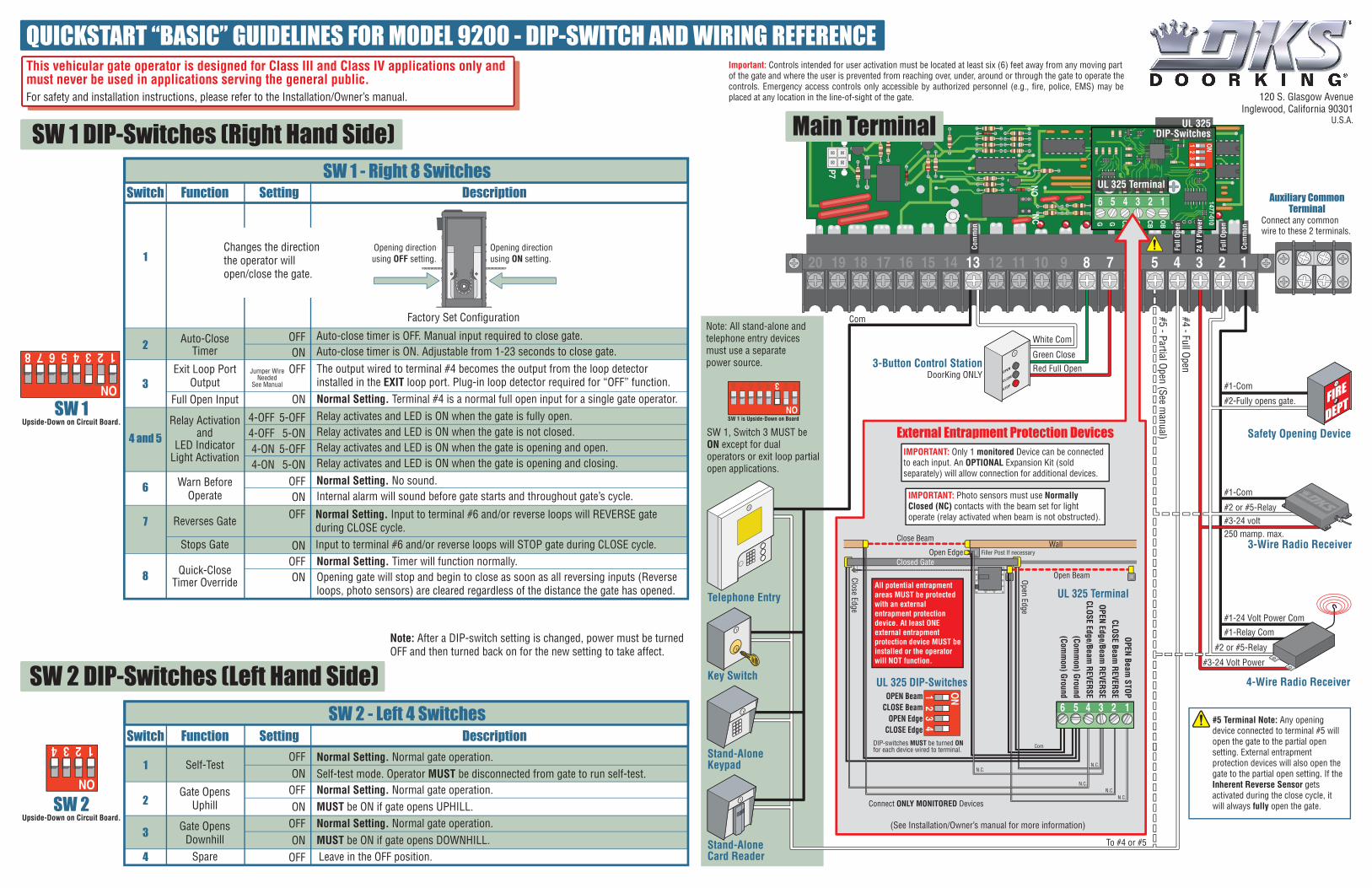
SW 1 DIP-Switches (Right Hand Side)
SW 2 DIP-Switches (Left Hand Side)
NCNO
P7
20 19 18 17 16 15 14 13 12 11 10 9 8 7 6 5 4 3 2 1
Red Full OpenGreen Close
White Com
Key Switch
Stand-AloneKeypad
Stand-AloneCard Reader
Telephone Entry
3-Button Control StationDoorKing ONLY
Note: All stand-alone and telephone entry devices must use a separate power source.
#1-Com
#1-Com
#5 - Partial Open (See manual)
#4 - Full Open
Com
To #4 or #5
#2 or #5-Relay
250 mamp. max.#3-24 volt
#1-Relay Com
#2 or #5-Relay
#1-24 Volt Power Com
#3-24 Volt Power
4-Wire Radio Receiver
#2-Fully opens gate.
3-Wire Radio Receiver
Safety Opening Device
#5 Terminal Note: Any opening device connected to terminal #5 will open the gate to the partial open setting. External entrapment protection devices will also open the gate to the partial open setting. If the Inherent Reverse Sensor gets activated during the close cycle, it will always fully open the gate.
1
ON
2345678
SW 1 is Upside-Down on Board
Auxiliary CommonTerminal
Connect any common wire to these 2 terminals.
SW 1, Switch 3 MUST be ON except for dual operators or exit loop partial open applications.
Main Terminal
1
ON
2345678
1
ON
234 Switch Function Setting DescriptionSW 2 - Left 4 Switches
2
Spare4
1 Self-Test
Gate OpensUphill
3 Gate OpensDownhill
OFFON
Normal Setting. Normal gate operation.Self-test mode. Operator MUST be disconnected from gate to run self-test.
OFFON
Normal Setting. Normal gate operation.MUST be ON if gate opens UPHILL.
OFFON
Normal Setting. Normal gate operation.MUST be ON if gate opens DOWNHILL.
OFF Leave in the OFF position.
SW 1Upside-Down on Circuit Board.
SW 2Upside-Down on Circuit Board.
Exit Loop PortOutput
Full Open Input
Factory Set Configuration
Warn BeforeOperate
The output wired to terminal #4 becomes the output from the loop detector installed in the EXIT loop port. Plug-in loop detector required for “OFF” function. Normal Setting. Terminal #4 is a normal full open input for a single gate operator.
Reverses Gate
Stops Gate
Switch Function Setting DescriptionSW 1 - Right 8 Switches
OFFON
4-OFF4-OFF4-ON4-ON
5-OFF5-ON
5-OFF5-ON
Auto-CloseTimer
Relay Activationand
LED IndicatorLight Activation
2
1
3
4 and 5
7
8
OFFON
OFF
ON
Normal Setting. No sound.Internal alarm will sound before gate starts and throughout gate’s cycle.
Auto-close timer is OFF. Manual input required to close gate.Auto-close timer is ON. Adjustable from 1-23 seconds to close gate.
6
Relay activates and LED is ON when the gate is fully open. Relay activates and LED is ON when the gate is not closed.Relay activates and LED is ON when the gate is opening and open. Relay activates and LED is ON when the gate is opening and closing.
Changes the direction the operator will open/close the gate.
Opening directionusing ON setting.
Opening directionusing OFF setting.
OFFON
Normal Setting. Timer will function normally.Opening gate will stop and begin to close as soon as all reversing inputs (Reverse loops, photo sensors) are cleared regardless of the distance the gate has opened.
OFF
ON
Normal Setting. Input to terminal #6 and/or reverse loops will REVERSE gate during CLOSE cycle.Input to terminal #6 and/or reverse loops will STOP gate during CLOSE cycle.
Quick-CloseTimer Override
Jumper WireNeeded
See Manual
Note: After a DIP-switch setting is changed, power must be turned OFF and then turned back on for the new setting to take affect.
OB
CBOE
CEGG
1 ON
1477-010SW
1
23
4UL 325 Terminal
SW1
UL 325DIP-Switches
Closed Gate
WallClose Beam
Open Beam
Filler Post If necessaryOpen Edge
IMPORTANT: Photo sensors must use Normally Closed (NC) contacts with the beam set for light operate (relay activated when beam is not obstructed).
External Entrapment Protection DevicesIMPORTANT: Only 1 monitored Device can be connected to each input. An OPTIONAL Expansion Kit (sold separately) will allow connection for additional devices.
UL 325 Terminal
Close Edge
Open Edge
DIP-switches MUST be turned ON for each device wired to terminal.
UL 325 DIP-Switches
N.C.N.C.
N.C.N.C.
Com
N.C.
Connect ONLY MONITORED Devices
1 ON
23
4
OPEN BeamCLOSE Beam
OPEN EdgeCLOSE Edge
(See Installation/Owner’s manual for more information)
123456
OPEN Beam STOP
CLOSE Beam REVERSE
OPEN Edge/Beam REVERSE
CLOSE Edge/Beam REVERSE
(Comm
on) Ground(Com
mon) Ground
123456
Full
Open
Full
Open
Com
mon
Com
mon
24 V
Pow
er
All potential entrapment areas MUST be protected with an external entrapment protection device. At least ONE external entrapment protection device MUST be installed or the operator will NOT function.
QUICKSTART “BASIC” GUIDELINES FOR MODEL 9200 - DIP-SWITCH AND WIRING REFERENCE
120 S. Glasgow AvenueInglewood, California 90301
U.S.A.
Important: Controls intended for user activation must be located at least six (6) feet away from any moving part of the gate and where the user is prevented from reaching over, under, around or through the gate to operate the controls. Emergency access controls only accessible by authorized personnel (e.g., fire, police, EMS) may be placed at any location in the line-of-sight of the gate.
This vehicular gate operator is designed for Class III and Class IV applications only and must never be used in applications serving the general public.For safety and installation instructions, please refer to the Installation/Owner’s manual.