r-314 - an experimental continuously reinforced … experimental continuously reinforced concrete...
TRANSCRIPT
' I
DECEMBER 1959
R- 31'/
STATE HIGHWAY DEPARTMENT
JOHN C. MACKIE COMMISSIONER

AN EXPERIMENTAL CONTINUOUSLY REINFORCED CONCRETE PAVEMENT IN MICHIGAN
Gene R. Cudney, Physical Research Engineer
Prepared for Presentation at The Thirty-Ninth Annual Meeting of the Highway Research Board
Washington, D. C., January 11-15, 1960
Report No. 314 Research Laboratory Division Office of Testing and Research
Research Project 57 F-46
Michigan State Highway Department John C. Mackie, Commissioner
Lansing, December 1959
SYNOPSIS
This paper summarizes the construction, instrumentation, observations, and measurements associated with an experimental continuously reinforced concrete pavement located on Interstate Highway 96, now designated US 16, near Portland, Michigan.
The experimental project includes two 24-ft roadways each containing two 12-ft lanes. Two types of reinforcing steel, deformed bar mat and welded wire mesh, each providing a steel ratio of approximately 0, 6 percent, were used in the continuously reinforced, 8-in. uniform pavement sections. The eastbound roadway is composed of a 2-mi section of continuous wire mesh, 0. 7 mi of standard 9-in. uniform pavement with contraction joints spaced at 99-ft intervals, and a 2-mi section of continuous bar mat. The westbound roadway contains approximately 4 mi of continuously reinforced pavement, 2 mi each of bar mat and wire mesh. Relief sections of 9-in. uniform pavement 493 ft long, consisting of eleven l-in. expansion joints, were placed at the ends of the continuously reinforced sections.
Construction methods and equipment are described, including construction joints in the continuously reinforced sections. Various characteristics associated with the construction phase of the project are discussed, including subgrade soil classification, concrete and air temperatures, concrete strength., and a record of construction progress.
Studies involved in comparing the performance of various project sections include longitudinal displacements of the ends, end regions and center of the continuously reinforced sections; relative displacements of joints and selected cracks; crack patterns and formation; surface roughness; effects oftraffic; performance of relief sections; and load-deflection behavior. In addition, one section each of bar mat, wire mesh, and standard mesh reinforcement was instrumented with strain gages for determination of steel stress variation.

CONTENTS
Page
LOCATION AND DESCRIPTION, , , • , , • , • , •••• , , • , •• , • , , , 1 Eastbound Roadway, •••• , • , • , •••• , • , , , , , , • , •• , , •• , • 3 Westbound Roadway.,.,,, .•.••.••. , ..• ,, .• ,.,, •.••. 3 Reinforcing Steel in Continuous Sections,,., ••. ,.,,,,, 6 Relief Sections,,, , , , • , • , • , , , ••• , , • , • , • , , , • , •. , . , .• , 6 Scope of Study .................. , . , , ..•• , , .•. , • , .•. 8
PAVEMENT CONSTRUCTION.,.,,,,,.,.,,.,,,.,.,,, ... 9 Sequence of Operations,., .. , •...•••..• , , . , , . , .• , , , 10 Construction Joint.~ • , .. , , . , , • , , , ..•• , , • , , •..• , . , . , 13
INSTRUMENTATION AND MEASUREMENTS.,,,, ••• , •••• 15 Preparations for Construction .•••• , , •• , • , , , , •• , • , , . 15 Operations During Construction .•.• , , • , , , , , , , , • , , •• ,19 Operations After Construction,,.,, , , ••••••••••••••• 22 Subsequent Course of Study , •••••••••••••••..•••.• , 26
APPENDICES A, !!Recommendations on Minimum Requirements
for Tests and Observations'' of the Highway Research Board Subcommittee on Continuously Reinforced Concrete Pavements , •• , •• , , ••• , •• , • 31
B. Instrumentation and Installation Details for Instrument13d Steel Reinforcement ••.•••••••••••• 33
C. Construction Data and Materials Characteristics,. 35
ILLUSTRATIONS Figure Page
1 - Location of experimental pavement. , •• , ..•••• , , •• , ••• , 2 2 - Typical road cross-section, . , . , ••• , , •••• , , , • , • , , •. , , 4 3 - Detailed drawings of heavy mesh, bar mat, and
standard reinforcement , , , , , , , , •••• , •• , •.• , •• , , •. , , , 5 4 - Typical expansion joint asseinbly and relief section,, ••• 6 5 - General plan and instrumentation layout, •• ,.,.,., ••• ,, 7 6 - Lap in continuous bar mat reinforcement •.. , , , , , • , • • • 11 7 - Lap in continuous wire mesh reinforcement .. , •. , •.•.. 11 8 - Spreading and striking off concrete with Blaw-Knox
spreader.,, , .. , , .•.• , , , , , . , , , , •• , •• , , , • , •.• , , , , , , .11 9 - Placing wire mesh reinforcement in continuous
section •...••••. , .• , •••. ,,,,, •. , •••.. ,, •.•.•.• ,, •. 11 10 - Placing-bar mat reinforcement in continuous section,, .11 11 - Placing final layer of concrete on bar mat reinforce-
ment. .. ,,., .......... ,,,,,,., .•..•. ,.,.,.,,, .. ,,, •• 11 12 -Spreading concrete with Jaeger.:. Lakewood finishing
machine in continuous wire mesh section .....• , , , , • • . 12 13 -Initial finishing of concrete surface with Jaeger-
Lakewood finishing machine , • , •.•.. , ••• _ •.•..•• , •• ,. 12 14- Final machine finishing with Heltzel Flexplane , , , . , , . 12 15 - Final hand finishing of cOncrete surface ...•.••• , . , , . , 12 16- Applying burlap drag finish to concrete surface,,,,,, ,.12 17- Applying white membrane curing compound ..••• ,.,, •• 12 18 - Details of construction joint headers ••• ,., •. , • , , , , •• , ,13 19 - Continuous wire mesh reinforcement placed over
lower set of 4 by 4's •••••• , , , •• ,, •• , , •• , • , •• , ....••. 14 20 - Wiring dowel bars to wire mesh reinforcement, .• , .••• 14
Figure Page
21- Continuous wire mesh reinforcement in place. through joint header •• ,,.,.,., •• , , , ••• , •• , , .• , • , , •• , •••• , .• 14
22 - Continuous bar mat reinforcement in place through joint header • , , , • , •• , •••••• , , •• , • , , • , ••• , •••• , •• , •• 14
23 - Burlap covering on extended bar mat reinforcement ..• 14 24 - Typical joint in wire mesh reinforcement after con-
crete set •.. , , .•.• , ..•.••••• , , • , , , , , •• , •••.• , , • , •••• 14 25 - Assembly drawing of pavement displaceometer, •• , •. ,. 17 26 - Details of strain gage placement and corrugated
crack former • , •• , , , , • , . , • , • , • , , , •••..•• , • , , • , ••• , .18 27- Taking slab temperature and steel depth measure-
ments ••• ,,.,,.,,, •••• ,.,.,,,.,,.,,.,, •. , •••• , .• ,., 20 28 -Taking beam samples for modulus of rupture tests., •• 20 29 - Setting plugs for differential slab displacements ••••• , 20 30 - Finishing concrete surface after setting plugs , , • , •.•• 20 31- Instrumented bar mat reinforcement in place,, •• ,.,,, 20 32 - Instrumented wire mesh reinforcement in place ••• , ••. 20 33 - Placing plastic tube containing thermocouples in sub-
base., ••••.••• , •••• ,., ••••••.••.• ·-· ••••••••••••.• 20 34 - Instrumented wire mesh reinforcement with corru-
gated crack former and thermocouples.,.,,, •• , ••••••• 21 35 - Instrumented standard mesh reinforcement with
corrugated crack former,., •• ,, •• ,,,,, •. , •• ,, •••• , •• 21 36 - Spreading concrete from bucket behind instrumented
standard mesh reinforcement,,,, •• ,,, .•• ,,,,.,., ••. , 21 37- Placing concrete around corrugated crack former in
heavy mesh reinforcement,., ••••• ,.,, •• ,, .•.•• ,, •••• 21 38 - Pushing concrete into instrumented standard mesh
reinforcement., •• ,,.,.,., .•.••.. ,., ••• ,, ••.••.• , .• 21 39 - Vibrating concrete adjacent to instrumented standard
mesh reinforcement.,, •..••••• , ••. , •••• ,, ••••• , •••• 21 40- Wiring strain gage and thermocouple leads at junction
box,, •.•••• ,, ••• ,,,,, •• , •• , ••••••••... , ••• ,,, •••• 21 41 - Measuring relative joint displacement in relief section
with vernier caliPers • , , . , , .•..••. , .. , ••• , • , , ••• , • , 23 42 - Setting monument for absolute slab displacement, .•••. 23 43 -Measuring absolute slab displacement with pavement
displaceometer .• , •.• , ••••• ,,.,., , •• , ..•••.•.•.•••• 23 44 - Measuring sectional slab displacement with vernier
calipers and invar tape. , , , •••• , ••• , , •.•••.••. , .• , • , ,23 45 -- Plugs set in epoxy resin for crack opening measure-
ments.,,, ••.•..•••.•• , •• ,,,, .•• , ...••• ,.,., •• ,, •.• 24 46 - Measuring surface crack opening with graduated scale
microscope., •..•.• , . , , • , , , ••• , • , ..•..••.••• , , ••••• 24 4-7 - Measuring crack opening with WhittemOJ.'e strain gage.-. 24 48 - MSHD roughometer truck. , •. , .•. , ••••• , , , ••••• , . , • • 24 49 - Subgrade soil classification (AASHO classification
system),, .. ,,, .••..••.. ,,, ••..•••...•..•••••• , •••• 37 50 - Steel reinforcement properties., .• ,, •••..• , •••••••• , ,38
AN EXPERIMENTAL CONTINUOUSLY REINFORCED CONCRETE PAVEMENT IN MICHIGAN
This report outlines the location and description, scope of study, general construction aspects, and the methods of instrumentation and measurements of an experimental continuously reinforced concrete pavement. No attempt is made here to present performance data recorded so far or to present the results of such data.
The discussion consists of three parts: the first includes the description, location, and scope of the project. The second presents the general construction features. The third describes the methods of instrumentation and measurements, and the course of study to be carried out in the future. A selective bibliography lists literature on the subject of continuously reinforced concrete pavement.
Appendices include: "Recommendations on· Minimum Requirements for Tests and Observations" prepared by the Highway Research Board Subcommittee on Continuously Reinforced Concrete Pavements; instrumentation and installation detalls for the instrumented steel 'reinforcement; and construction data and materials characteristics, including steel reinforcement properties, air temperature variation, concrete strength, construction progress data, and subgrade soil classification.
The organization of the program of observations and tests on this project coincides in general with the HRB "Recommendations" (App. A). Two other subjects included as additional features of the research project are the strain gage instrumentation of the steel reinforcement for strain analysis, and the load-deflection study of both the continuous and standard pavement sections.
LOCATION AND DESCIUPTION
After study and inspection of certain existing continuously reinforced pavements, the Michigan State Highway Department authorized construction of an experimental pavement of this type in 1957, with the primary purpose of studying durability, construction efficiency, and costs, as
TO
compared to current standard pavement construction practice. The detailed design and layout of the pavement were made by the Bridge and Road DesignDivision. Instrumentationof theproject during construction, and the necessary research and evaluation studies after construction, became the responsibility of the Research Laboratory Division.
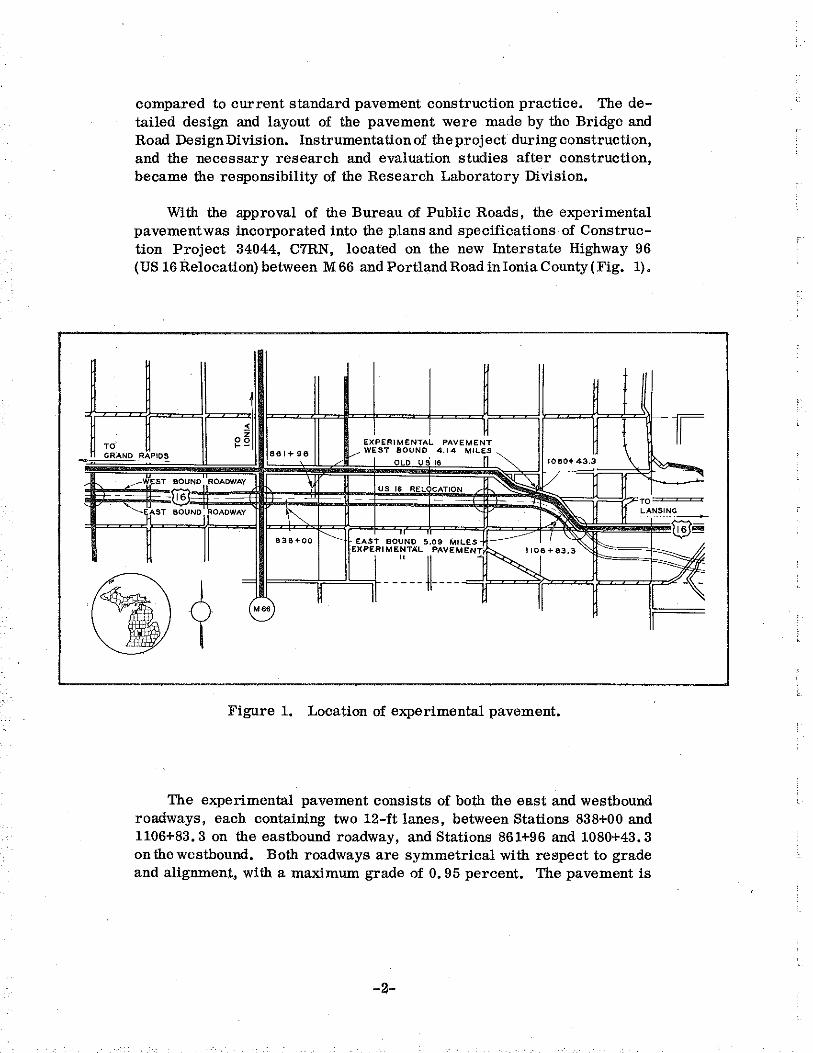
With the approval of the Bureau of Public Roads, the experimental pavement was incorporated into the plans and specifications of Construction Project 34044, C7RN, located on the new Interstate Highway 96 (US 16 Relocation) between M 66 and Portland Road in Ionia County (Fig. 1).
~ 0 ~1 ' ~-
EXPERIMENTAL PAVEMENT
GRAND RAPIDS 861+96 1----- WEST BOUND' 4.14 MILnS 1080+ 43.~ \ OLD US 16
___.WEST BOUND ROADWAY 11 / ®
US IS RELOCATION
- - TO
r ~
:'
,, ST BOUND OADWAY ~ - LANSING
•
838+00
------EAST B0~
1
NO 5.09 MILES I
EXPERI~~:T:~ fV_E~EN! ·~··•3.3
' M66
Figure 1. Location of experimental pavement.
The experimental pavement consists of bo:th the east and westbound roadways, each containing two 12-ft lanes, between Stations 838+00 and 1106+83. 3 on the eastbound roadway, and Stations 861+96 and 1080+43. 3 on the westbound. Both roadways are symmetrical with respect to grade and alignment, with a maximum grade of 0. 95 percent. The pavement is
-2-
B>-~
Z\

straightexcept fora 1°30' curve, 1, 616ft long, between Stations 1071+40 and 1087+56, and asimilarcurve beginning at Station 1100+40.03 in which the final.642 ft of the eastbound roadway is located. All continuously reinforced sections are 8-in. uniform, and all standard reinforced sections are 9-in. uniform thickness.
The concrete mix was designed by the mortar voids method of proportioning, with a constant cement content of 5-1/2 sacks per cu yd. Air entrainment of the concrete was provided by the addition of Darex AEA to the mix. The concrete had an average air content of 5. 4 percent and an average slump of 2 in.
The entire pavement was placed on a 12-in. granular subbase overlying in general a Type A-4 clay subgrade. A typical road cross-section is shown in Fig. 2.
The experimental pavement is composed of four distinct parts: continuously reinforced sections with deformed bar mat, continuously reinforced sections with welded wire mesh, a standard section with contracti~n joints spaced at 99ft, and the relief sections at the ends of the continuously reinforced portions. Drawings of the reinforcement and of a typical relief section are shown in Figs. 3 and 4. The general plan and instrumentation layout of the entire test project is shown in Fig. 5.
Eastbound Roadway
1. 10, 557 ft of 8-in. uniform pavement continuously reinforced with wire mesh.
2. 3, 804 ft of 9-in. uniform standard reinforced pavement with contraction joints at 99-ft intervals.
3. 10, 550 ft of 8-in. uniform pavement continuously reinforced with bar mat.
4. Four relief sections each 493 ft long, of 9-in. uniform standard reinforced pavement.
Westbound Roadway
1. 10,331 ft of 8-in. uniform pavement continuously reinforced with wire mesh.
2. 10, 530 ftof 8-in. uniform pavement continuously reinforced with bar mat.
3. Two relief sections each 493 ft long, of 9-in. uniform standard reinforced pavement.
-3-

<t_ OF MEDIAN
2' 15.4 1 ------~~
t I Jl GRADE
otl
'I <'l
PER FT
4' v.c.
47' <t.
OF ROADWAY
7. 4 , 8 '-----+-----
AGG. BASE COURSE 6" DEPTH
8 11 UNIFORM
RIME AND __,.---'--~"BLE SEAL
I ~,CROWN 8
9" SUBBASE
3" SELECTED SUBSASE
I" 2 PER
TOPSOIL SURFACE ON UNSODDED SLOPES AND DITCHES
ROUND BOTTOM DITCH. WIDTH, DEPTH, AND BACKSLOPE AS CALLED FOR ON PLANS
Figure 2. Typical road cross-section.
'~-7--

' "' I
r
I -N
' ·w
1
r-or-<0
' -<0
" N
" ' w
:, "' w
~ "' Q
L__ 1-
16'-o"
1'-1"12'-5"14 SPACES AT 2'-3''= 9'-o" 12'-5"11'-1"1-
! I
7 REQ' D PER HALF MAT II REQ'D PER HALF MAT
CONTINUOUS REINFORCED CONCRETE PAVEMENT BAR MAT REINFORCEMENT FOR 8" SLAB
(ASSEMBLED MAT, 399.60 LB PER 12' LANE -19.27 LB PER SO YD )
1 12'-o"-------<
6"1 r-" SPACES AT 1'-0" 11'-0" -, ~S"
1
_.fLim-~ -<0 if) if)
~~-r "'"' N<O
~
L~::::J=I=1=1=~ T' \~ONGIT~DIN1
AL 'wldEs NO.
1
s;o's 'GA~~ "'-- TRANSVERSE WIRE NO. I GAGE ::J
'"OVERHANG
CONTINUOUS REINFORCED CONCRETE PAVEMENT MESH REINFORCEMENT FOR 8" SLAB
(ASSEMBLED MAT, 303.00 LB PER 12' LANE-19.76 LS PER SQ YD)
10'- 0" LENGTH OF SHEET ~ ......-js"r--- 10 TRANSVERSE WIRES AT 12" CENTERS 16"
I : ' ' 1 NO. '4 GA~E ' ' ' '
---
"' -oc w -~ z -w u -
-w
' -w
" -- ~ -- <(•
>- 0 <n<-w w 0
w oc. -I ~~-"' " ~ -' . -0 <Co
I zz-
9 0 -~
~ ~ -" I
z -0 -' -~
l N -! -I i I -
LL_L ~OVERHANG ON EACH SIDE NOT MORE THAN 1°
STANDARD REINFORCEMENT (ASSEMBLED MAT, 85.9 LB PER 12' LANE-7.2 LB PER SQ YO)
Figure 3. Detailed drawings of heavy mesh, bar mat, and standard reinforcement.
Reinforcing Steel in Continuous Sections
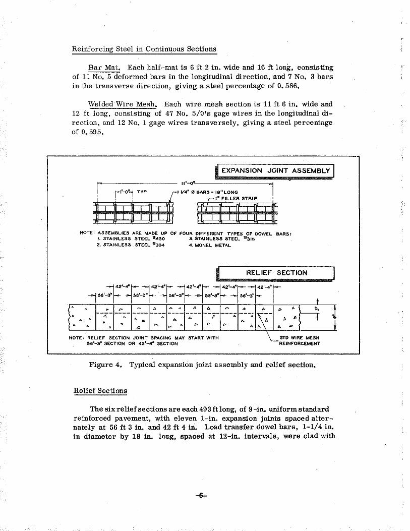
Bar Mat. Each half-mat is 6 ft 2 in. wide and 16 ft long, consisting of 11 No. 5 deformed bars in the longitudinal direction, and 7 No. 3 bars in the transverse direction, giving a steel percentage of 0. 586.
Welded Wire Mesh. Each wire mesh section is 11 ft 6 in. wide and 12 ft long, consisting of 47 No. 5/0's gage wires in the longitudinal direction, and 12 No. 1 gage wires transversely, giving a steel percentage of 0. 595.
• EXPANSION JOINT ASSEMBLY I a I' 11'-o" I 1I-faitr:i' ~·. ~ ... ····~' ' ' ' MO!tt
NOTE: ASSEMBLIES ARE MADE UP OF FOUR DIFFERENT TYPES OF DOWEL BARS: I. STAINLESS STEEL #430 3, STAINLESS STEEL 31316 2. STAINLESS .STEEL '*304 4. MONEL METAL
I RELIEF SECTION
~···-f·-:r.:·-~·-~··:f·::r..·:t2
·:j:·f2
·-4·r I • • • '" = ~ ~ . " " Co "" .. "'
A ;., .! ---- ---- ---- ---- ----~~- ~ • 4 ~ • A p • • • A .. • • • b A ..
I . • • - b • I> "' A • A D A A p
NOTE: RELIEF SECTION JOINT SPACING MAY START WITH ~STD WIRE MESH 58 1-3• SECTION OR 42 1-4'1 SECTION REINFORCEMENT
Figure 4. Typical expansion joint assembly and relief section.
Relief Sections
The six relief sections are each 493ft long, of 9 -in. uniform standard reinforced pavement, with eleven l-in. expansion joints spaced alternately at 56ft 3 in. and 42ft 4 in. Load transfer dowel bars, 1-1/4 in. in diameter by 18 in. long, spaced at 12-in. intervals, were clad with
-6-

i i
!.
,
' l ' S' t g
~ 0 >, ol .... l'l 0 'P
~ ., ~ .tl ~ ·~
1l ol
§ .... "" ';;l .... 2:1
c3
"' ., .... g, ·~
z '"' zo ~i= •hl "" <e ~---~" "" 0

corrosion resistant alloy sleeves to prolong service life and to provide more freedom of movement for the expansion joints in the relief sections. Four of the six relief sections contained one of three types of stainless steel-clad bars, Types 304, 316, or 430, and the remaining two relief sections contained monel-clad dowel bars. The minimum sleeve thickness for the Type 430stainless steel-clad bars was 0. 015 in., while the Types 304 and 316 stainless steel and the monel-clad bars had a minimum sleeve thickness of o. 010 in. All the bars were coated with a cutback asphalt and inserted in standard l-in. expansion joint assemblies prior to installation in the pavement.
In addition, eight consecutive contraction joints in a section of 9-in. uniform standard pavement outside the limits of the continuously reinforced test pavement were composed of standard contraction joint assemblies, containing 1-1/4- by 18-in. nickel coated hot-rolled steel bars. Performance of this section, along with that of the l-in. expansion joints in the six relief sections, will be studied as part of the Department's research project on dowel bar corrosion.
Scope of Study
In order to properly evaluate and compare the performance of the various sections of the project, the following factors are being studied:
1. Magnitude and variation of absolute longitudinal displacement of the ends of the continuously reinforced sections.
2. Magnitude and variation of longitudinal displacements of the center and end regions of the continuously reinforced sections.
3. Magnitude and variation of the relative longitudinal displacements of joints and cracks in both the standard and continuous sections.
4. Magnitude and variation of crack openings in various regions of the continuous sections.
5. Magnitude and variation of stresses in the bar mat, wire mesh, and standard reinforcement.
6. Initial surface roughness and roughness changes with time and traffic.
7. Static and dynamic load-deflection characteristics at various points in the standard and continuous sections.
8. Function of relief sections in relation to slab performance. 9. Effect of traffic on pavement performance in all sections.
-8-
L·

i.
To correlate these itemswithslabperformance, the following studies are included:
1. Soil types and characteristics of the subbase and subgrade. 2. Physical properties of the reinforcing steel. 3. Physical properties of the concrete. 4. Steel stresses in relation to slab temperature variation.
Throughout the entire project, various measuring devices and equipment are being used:
1. SR-4 electrical resistance wire strain gages and an SR-4 static strain indicator for determining steel reinforcement strains.
2. Thermocouples for slab temperature determination. 3. Reference monuments and a displacement device for determining
the movements of the ends of continuous pavement sections. 4. Reference ·plugs for measurement of relative joint and crack
displacement. 5. Vernier calipers and an invar tape for measurement of relative
joint displacement and sectional slab displacement. 6. Whittemore mechanical strain gage and a scale microscope for
measurement of crack openings.
PAVEMENT CONSTRUCTION
Construction of the experimental pavement began September 22, 1958, and paving operations were completed October 20, 1958. Double lane construction was employed, whereby the entire 24-ft width of pavement was placed at one time. No. 4 deformed bars, 30 in. long, were spaced at 40 in. on all sections of the test pavement as transverse tie bars between the two 12-ft lanes, with the longitudinal centerline joint sawed and sealed at a later time. All the contraction joints in the standard section contained load transfer assemblies consisting of 1-1/ 4-in. diameter bars 18 in. long, spaced at 12-in. centers.
The steel reinforcement was placed 3 in. below the surface in the 8-in. uniform continuous sections, as well as in the 9-in. uniform standard section. The steel in the continuous bar mat sections was lapped 13 in. , with the ends of the longitudinal bars placed against the last transverse bar of the preceding mat. The continuous mesh was lapped 12 in. , so that the first transverse wire of the mesh being laid rested behind the
-9-

last transverse wire of the preceding mesh section. The laps in both the bar mat and wire mesh reinforcement are shown in Figs. 6 and 7.
The continuous mesh reinforcement was transpor.ted to the construc·tion area on trucks or flatbed trailers, and placed in the pavement from the trucks as reqnired. The bar mat reinforcement was spread out in piles approximately 75 ft apart along the shoulder slopes in advance of construction, where it would be readily available as needed.
In constructing the pavement slab, the contractor used two Koehring 34E dual drum mixers, a Blaw-Knox spreader, two Jaeger-Lakewood
·finishing machines, and a Heltzel Flexplane. The maximum pavement lengths attained in a day's pour were 3, 100 :ft in the continuous mesh sections and 3, 500ft in the bar mat sections. The average lengths poured ina day were 2,500 ft for the continuous mesh and 3, 086 ft in the bar mat.
Sequence of Operations
The sequence of construction operations for both the standard and continuously reinforced sections, illustrated in Figs. 8-17, was as follows:
1. Placing concrete on subbase from first mixer.
2. Spreading and striking off concrete 3 in. below finished surface with Blaw-Knox spreader.
3. Placing steel reinforcement.
4. Placing transverse tie bars.
5. Placing final layer of concrete from second mixer.
6. Spreading and screeding concrete with Jaeger-Lakewood finishing machine.
7. Initial finishing of concrete surface with second Jaeger-Lakewood machine.
8. Final machine finishing of concrete surface with Heltzel Flexplane.
9. Final hand finishing of concrete surface.
10. Applying burlap drag finish to concrete surface.
11. Applying white membrane curing compound.
-10-

Figure 7 •
...A... Figure 8. Spreading and striking off concrete with Blaw -Knox spreader.
Figure 9. Placing wire mesh reinforcement in continuous section,
Figure 10. Placing bar mat reinforcement in continuous section.
Figure 11, Placing final layer of concrete on bar mat reinforcement.
-11-

........ Figure 12. Spreading concrete with Jaeger-Lakewood finishing machine in continuous wire mesh section,
Figure 14. Final machine finishing with Heltzel Flexplane,
Figure 15, Final hand finishing of concrete
' ~ Figure 16, Applying burlap drag finish to concrete ~surface.
Applying white membrane curing com-
- 12 -
Construction Joints
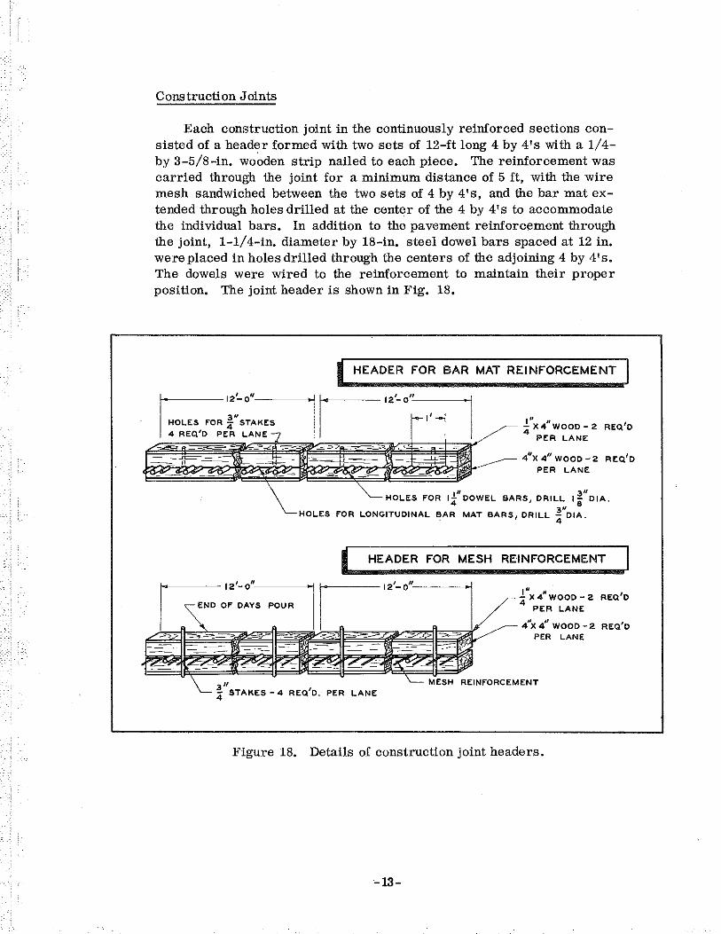
Each construction joint in the continuously reinforced sections consisted of a header formed with two sets of 12-ft long 4 by 4's with a 1/4-by 3-5/8-in. wo~den strip nailed to each piece. The reinforcement was carried through the joint for a minimum distance of 5 ft, with the wire mesh sandwiched between the two sets of 4 by 4's, and the bar mat extended through holes drilled at the center of the 4 by 4' s to accommodate the individual bars. In addition to the pavement reinforcement through the joint, 1-1/ 4-in. diameter by 18-in. steel dowel bars spaced at 12 in. were placed in holes drilled through the centers of the adjoining 4 by 4's. The dowels were wired to the reinforcement to maintain their proper position. The joint header is shown in Fig. 18.
HEADER FOR BAR MAT REINFORCEMENT
I" , 4 X4 WOOD- 2 REQ1D PER LANE
411
X 4 11 WOOD -2 REQ1D PER LANE
1" 3 11
HOLES FOR l4 DOWEL BARS, DRILL I i DIA. 3" HOLES fOR LONGITUDINAL BAR MAT BAR 5 1 DRILL 4 OIA.
I HEADER FOR MESH REINFORCEMENT
.!"x 4 11 WOOD- 2 REQ'D
4 PER LANE
411X 4
11 WOOD -2 REQ'D
PER LANE
a" 4 STAKES -4 REQ1D. PER LANE
Figure 18. Details of construction joint headers.
-13-

Figure 22. Continuous bar mat reinforcement in place
through joint header.
Burlap covering on extended bar mat reinforce-
Figure 24. Typical joint in wire mesh reinforcement after
concrete set.
- 14 -
The portion of the reinforcement extending through the joint was supported on boards which kept the steel level and made it easier to align the dowel bars. The concrete was hand vibrated throughout the width of the joint and about 5 ft back along the side forms. Burlap was placed over the extended reinforcement to catch excess concrete spilling over the header during finishing operations. Construction is shown in Figs. 19 through 24.
The first section of reinforcement placed the following morning was single lapped, With the exception of two joints in the wire mesh reinforcement in which the steel was double lapped. In addition, two joints in the bar mat and two in the wire mesh sections contained dowel bars previously coated with an RC-1 cutback asphalt. The remaining joints contained uncoated bars.
INSTRUMENTATION AND MEASUREMENTS
This discussion pertains to the methods of instrumentation and observations carried out to determine and evaluate the various factors involved in the study. It is Qivided in four phases, encompassing preparations prior to construction, observations and instrumentation during construction, measurements and instrumentation after construction, and finally, the course of study to be pursued in the future. The description of each phase includes the measurements, observations, and instrumentation involved.
Preparations for Construction
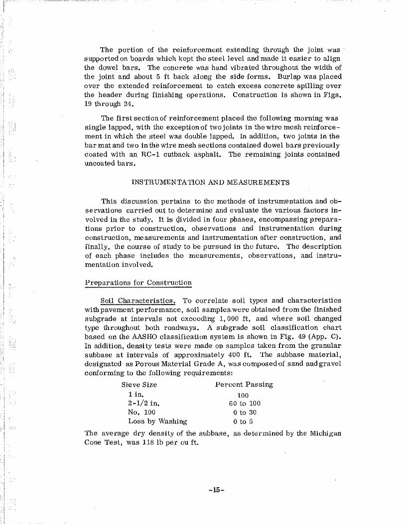
Soil Characteristics. To correlate soil types and characteristics with pavement performance, soil samples. were obtained from the finished subgrade at intervals not exceeding 1, 000 ft, and where soil changed type throughout both roadways. A subgrade soil classification chart based on the AASHO classification system is shown in Fig. 49 (App. C). In addition, density tests were made on samples taken from the granular subbase at intervals of approximately 400 ft. The subbase material, designated as Porous Material Grade A, was composed of sand and gravel conforming to the following requirements:
Sieve Size 1 in. 2-1/2 in. No. 100 Loss by Washing
Percent Passing
100 60 to 100
0 to 30 0 to 5
The average dry density of the subbase, as determined by the Michigan Cone Test, was 118 lb per cu ft.
-15-

Absolute Slab Displacement. To determine the absolute displacement of the ends of the continuous pavement sections, a device was constructed consisting essentially of three movable arms forming a right triangle, with two 0, 001-in. Federal dials fixed to two of the arms (Fig. 25). This instrument, when attached to a fixed base and leveled, provides a means of measuring both the longitudinal and lateral displacement of a point on the concrete surface. In conjunction with this instrument, a steel reference bar was made to determine temperature deformations of the device itself, and also to check on the initial settings of the dial gages. Seven reinforced concrete monuments, 6-3/16 in. in diameter and 5 ft long, were constructed to provide fixed points for measurements of absolute slab movement. The top of each monument contains a brass plate, with brass bushings to accommodate the base of the pavement displaceometer.
Gage Plugs. All the gage plugs used in conjunction with measurement of joint and slab displacements, and crack opening variations, were formed from 1/4-in. diameter stainless steel countersunk head rivets, with appropriately machined conical holes or scratched crosshairs in the rivet heads.
Physical Properties of the Reinforcing Steel. Five specimens each of the continuous wire mesh, bar mat, and standard mesh reinforcements were sampled and subjected to tensile tests to determine yield stress, ultimate stress, and percentage elongation characteristics. Physical properties of the three types of steel reinforcement are shown in Fig. 50 (App. C).
Instrumented Reinforcing Steel. Type A-12 SR-4 strain gages were placed on the three types of steel reinforcement as follows:
1. Bar Mat. Gages placed on five longitudinal bars, so that when a complete mat was in place in the 12-ft traffic lane, the fourth and seventh bars from each lane edge, and the eleventh bar from the outside lane edge were instrumented.
2. Continuous Wire Mesh. Gages placed on five longitudinal wires, so that when a complete mesh section was in place in the 12-ft traffic lane, the fifth and fourteenth wires from each lane edge, and the twenty-third wire from the outside lane edge were instrumented.
3. Standard Wire Mesh. Gages placed on five longitudinal wires in same positions as for bar mat.
-16-
(_.

I
4 I
/
POSITJON OF FEDERAL .001"- 3" THROW DIAL __ GAGE
/ ' / ',
/ ' ----<----- '----T
' '
4
12
24
25 6 3/16" DIA. CONCRETE MONUMENT 5 FT LONG
,.
,'f::'
.~;1'
Figure 25. Assembly drawing of pavement displaceometer.

' ::;;; I
~ "' =~ -+--11;
"N _t -"' <:
J_i -!!1
=t-N '
-"'
I
X- INDICATES DOUBLE A-12 TYPE SR-4 STRAIN GAGES
_j __l
1 11•111111
<'! 1_1
il
PASSING LANE
STANDARD REINFORCEMENT
~ 1
="' <'!
=t ~
=i 1
=
PASSING LANE
_l
MESH REINFORCEMENT
=-'"" _1 --IN
"' =~ _t-~
J;-"' =-i'N i_
PASSING LANE
__l
-v
u ,1
BAR MAT REINFORCEMENT
NOTE: REINFORCEMENT WITHOUT INSTRUMENTATION IN PASSING LANE. ALL GAGES MOUNTED AT CENTER OF MAT.
L ;., DD-2 PIECES OF 28 GAGE CORRUGATED SHEET STEEL
I I I I '"t- 20 GAGE SHEET STEEL ----..f 3 11 1-- 1--111 -11 11---t
CORRUGATED CRACK FORMER
Figure 26. Details of strain gage placement and corrugated crack former.

i !
A detailed description of the instrumentation and installation for the instrumented steel reinforcement may be found in Appendix B, and placement of the strain gages is shown in Fig. 26.
Induced Cracks at Instrumented Steel Locations. To ensure formation of a crack at each of the instrumented steel locations, three units were constructed, each formed of two 12-ft lengths of No. 28 gage corrugated steel, 3 in. high, welded to a piece of No. 20 gage sheet steel. This corrugated crack former is shown in Fig. 26.
Operations During Construction
The operations described here are shown in Figs. 27 through 40.
Air Temperature. A record of daily air temperature throughout the construction period was obtained by means of a Honeywell automatic temperature recorder. Table 1 (App. C) shows the high, mean, and low temperatures for each 24-hr day throughout the construction period, plus an additional 11 days after the experimental pavement was completed,
Concrete Temperature and Steel Depth. The mid-depth concrete temperature and steel depth were measured at two points in each lane at intervals of 200ft throughout the entire test pavement. These measurements were taken just before the final hand finishing operation.
Concrete Properties. One test cylinder and one beam for modulus of rupture tests were taken at intervals of approximately 600 ft throughout the test pavement. Half these samples were tested at 7 days and half at 28 days. Other pertinent concrete characteristics were determined and recorded in the daily construction reports. Modulus of rupture and compressive strength values, as well as daily construction progress and air temperature during construction, are shown in Table 2 (App. C).
Construction Conditions. All events pertinent to construction and the possible effects on pavement performance were recorded each day throughout the construction period.
Placing Plugs for Relative Joint Movement. A set of gage plugs was placed at each joint in the six relief sections, at all construction joints in the continuously reinforced sections, and at ten consecutive contraction joints in the standard pavement section. All plugs were placed in the concrete just after the final hand finishing operation, 4 in. each side of the joint centerline and 12 in. from the pavement edge in the traffic lane.
-19-

Figure 27. Taking slab temperature and steel depth measurements.
Figure 28, Taking beam samples for modulus of rupture tests.
Figure 29, Setting plugs for differential slab displacements . ....,...
Figure 30. Finishing concrete surface after setting plugs,
Figure 31. Instrumented bar mat reinforcement in place.
- 20-

~ Figure 34, Instrumented wire mesh reinforcement with corrugated crack former and thermocouples,
Figure 36. Spreading concrete from bucket behind instrumented standard mesh reinforcement.
Figure 35, Instrumented standard mesh reinforcement'with corrugated crack former,
Figure 37. Placing concrete around corrugated crack former in heavy mesh reinforcement.
Figure 39, Vibrating concrete adjacent to instrumented standard mesh reinforcement.
- 21-
Figure 40. Wiring strain gage and thermocouple leads at junction box.

Placing Plugs for Absolute Slab Movement. Onegageplugwasplaced in the concrete after the final hand finishing operation, 4 in. from the ends of the continuously reinforced sections and 12 in. from the pavement edge in the passing lane. Similarly, a gage plug was installed 4 in. from the beginning joint of the ten consecutive contraction joints in the standard section.
Placing Plugs for Sectional Slab Displacement. A set of sevenplugs, beginning at the ends of the continuously reinforced sections and spaced 99 ft apart for 693 ft, were placed 12 in. from the pavement edge in the passing lane. In addition, a set of five plugs, similarly spaced, were placed in the center 495-ft region of a day's pour in each of the baT mat and wire mesh continuous sections.
Placing Instrumented Steel. The instrumented continuous reinforcement was placed in the traffic lane, approximately in the center region of a day's pour. The instrumented standard mesh was placed in the traffic lane halfway between contraction joints. In all cases, the reinforcement (including the passing lane) was supported on wire chairs in advanceof construction. Each wire or bar was taped for the same length as those with attached SR-4 strain gages, to maintain the same bonding characteristics across the 24-ft pavement. Concrete was poured and spread up to the instrumented section, which was then bypassed. Next, regular reinforcement was laid, working backward from the instrumented steel for approximately 50 ft, to ensure a proper lap in the immediate vicinity of the instrumented reinforcement. The concrete was carefully placed over the instrumented reinforcement to prevent any gage damage. The concrete area adjacent to the transverse gage line of the reinforcement was then vibrated across the full pavement width.
Placing Thermocouples. Two sets of three thermocouples each were placed at each of the three instrumented steel locations described above. Each set was placed 12 in. from the corrugated crack former and 18 in. from each edge of the traffic lane. The thermocouples were placed in a plastic tube so that one was an inch from the slab bottom, one at middepth, and one an inch from the top surface.
Operations After Construction
Operations during the months immediately following construction are shown in Figs. 41 through 48.
-22-

~ Figure 41. Measuring relative joint displacement in relief section with vernier calipers.
Figure 42. Setting monument for absolute slab displacement.
Figure 43. Measuring absolute slab displacement with pavement displaceometer.
- 23-

~ Figure 45. Plugs set in epoxy resin for crack opening measurements.
Figure 47. Measuring crack opening with ~ Whittemore strain gage. ,
- 24-
, ~ Figure 46. Measuring surface crack opening with graduated scale microscope.

Joint and Slab Measurements. Initial readings were obtained on all expansion joints in the relief sections, all construction joints in the continuous sections, and the ten construction joints in the standard section just after initial set of the concrete, with a Starrett o. 001-in. vernier caliper.
The concrete monuments were set in the shoulde.r 5 in. from the pavement edge at the previously described seven locations, within two days after the concrete slab had been poured, Initial measurements were made at this time with the pavement displaceometer.
Incremental displacements of the six end regions and two central areas in the continuous sections were measured with a 100-ft invar tape coupled with the vernier calipers, the day after each section had been poured. In taking these measurements, a thin plastic plate With a conical hole and etched cross hairs is held on the mark of the invar tape. One end of the caliper fits into the gage plug, and the other sits in the plastic plate to obtain the reading.
Crack Survey. A continuous accumulative crack survey was conducted on the entire test pavement to determine the crack pattern, so that each day's pour was surveyed daily for the first five days and then on approximately the eighth, twelfth, and sixteenth days thereafter.
Crack Measurements. Eight sets of four cracks each were selected in the following regions of continuous reinforcement:
1. Near a contraction joint in each of the continuous mesh and bar mat sections.
2. Two sets each approximately 500 ft from the ends of the bar mat and continuous wire mesh sections.
3, One set in the center section of a day's pour in each of the bar mat and continuous mesh sections.
The first cracks appearing in these areas were selected and two gage plugs installed 5 in. each side of each crack, 12 in. from the pavement edge in the traffic lane. The plugs were set in Armstrong Type A-1 cement, and the initial reading taken about an hour later with a Whittemore 10-in. length mechanical strain gage. The average surface width of the crack across the gage line was also measured using a scale microscope graduated to o. 0004 in. This reading was applied as a correction to the initial Whittemore measurement. In addition, plugs were set and measurements taken in the same manner at the instrumented steel locations as soon as the cracks appeared.
-25-

Strain and Temperature. All strains and slab temperatures at the three instrumented steel sections were recorded daily until the induced cracks formed, then weekly until January 15, 1959. In addition, strain and temperature measurements were obtained for a 24-hr period after each induced crack formed.
Surface Roughness. The initial surface roughness indices for the various sections of the test pavement were obtained Aprill, 1959, approximately three months after the pavement was opened to traffic.
Crack Width Variation. Cores were taken in July 1959, at two of the wider cracks in each of the bar mat, continuous mesh and standard mesh rei~forced pavement areas.
Load-Deflection Tests. Load-deflection studies involving static and dynamic truck loadings were made in separate duplicate day and night tests in September 1959. Locations included a construction joint and an adjacent crack in the bar mat and the mesh sections, two points halfway between two adjacent cracks and at a crack in both the mesh and mat central regions, a contraction joint and two points midway between two contraction joints in the standard pavement. Deflection of these 13 points was measured at the outside edge of the traffic lane in all cases.
Subsequent Course of Study
The various factors included in this project will be evaluated in continuing observations over a period of years or until sufficient data have been obtained to warrant conclusions.
Air Temperature. The average monthly air temperature in the vicinity of the test site will be obtained throughout the project test period through a local station of the United States Weather Bureau.
Pavement Condition. The test pavement will be inspected on the 15th of January, April, July, and October each year throughout the testperiod. Photographs will be taken to record pavement performance characteristics.
Surface Roughness. Surface roughness will be determined once each year throughout the life of the project.
Crack Survey. A crack survey will be made on the 15th of January, April, July, and October of each year throughout the test period.
Traffic Survey. A traffic survey to determine axle weights and frequencies will be made once every three years throughout the test period.
-26-
l ~

Relative Joint Displacements. The relative displacement of all expansion joints in relief sections, ten contraction joints in the standard section, and all construction joints in the continuous sections will be Irnasured on the 15th of January, April, July, and October of each year throughout the test period.
Slab Displacements. The absolute movement of the ends and relative slab displacements in the center and end regions of the continuous sections will be measured on the 15th of January, April, July, and October of each year throughout the test period.
Strain and Temperature Measurements. Strains and slab temperatures of the three instrumented steel reinforced sections will be measured biweekly throughout the life of the strain gage and thermocouple instrumentation.
Crack Measurements. Surface width of the selected cracks in the end and center regions, and near construction joints in the continuously reinforced sections will be measured on the 15th of January, April, July, and October of each year throughout the test period. The cracks formed at the three instrumented steel reinforcement locations will be measured biweekly in conjunction with the regular strain and temperature readings.
Crack Width Variation. Cores will be taken at two of the wider cracks in each of the bar mat, continuous mesh, and standard mesh reinforced areas at five-year intervals throughout the life of the project.
Pictorial Crack Record. A progressive series of photographs of typical cracks in the center and end regions, and near construction joints in each of the bar mat and wire mesh continuous sections, will be taken each fall throughout the life of the project.
ACKNOWLEDGMENTS
The work described in this report was conducted under the general supervision of E. A. Finney, Director of the Research Laboratory Division, Michigan State Highway Department. The Laboratory is a Division of the Department's Office of Testing and Research, headed by W. W. McLaughlin, Testing and Research Engineer. The detailed design and layout of the experimental pavement was under the direction of Mr. H. Cash, Assistant Engineer of Bridge and Road Design.
-27-

The author expresses his gratitude to associates at the Laboratory for their able assistance, in particular to Mr. P. Milliman and his staff, who were responsible for the strain gage instrumentation and placement of the instrumented steel reinforcement, and to the project engineer and contractors 1 personnel for their fine assistance and cooperation.
REFERENCES
1. Cashell, H. D. , "Continuously Reinforced Concrete Pavements." Proc., 11th Ann. Virginia Hwy. Conf., p. 75 (1957).
2. Cashen, H. D., and Benham, S. W., "Continuous Reinforcement in Concrete Pavement." Public Roads, April 1950, p. 1.
3. Friberg, B. F., "Frictional Resistance Under Concrete Pavement and Restraint Stresses in Long Reinforced Slabs." Proc., HRB, Vol. 33, p. 167 (1954).
4. Gutzwiller, M. J., and Waling, J. L., "Laboratory Research on Pavements Continuously Reinforced with Welded Wire Fabric." HRB Bulletin 238 ( 1959).
5. Jacobs, W. H., Survey and Correlation Report on Continuously Reinforced Pavement Without Joints. Chicago: Rail Steel Bar Assn. ( 1953).
6. Jacobs, W. H., Report on the Results of the Continuously Reinforced Concrete Pavement Recently Completed on the Fort Worth-Dallas Freeway. Presented at ARBA 56th Ann. Conv. (1958).
7. Russell, H. W., and Lindsey, J. D., "An Experimental Continuously Reinforced Concrete Pavement in Illinois." Proc., HRB, Vol. 27, p. 42 (1947).
8. Shiffman, R. L. , Taylor, I. J. , and Eney, W. J. , "Preliminary Report on Continuously Reinforced Concrete Pavement Research in Pennsylvania." HRB Bulletin 181, p. 5 (1958),
9. Stanton, T. E., "Reports on Experiments with Continuous Reinforcement in Concrete Pavement - California." Proc., HRB, Vol. 30, p. 28 (1950).
-28-

10. Van Breeman, W., "Preliminary Report on Current Experiment wifu Continuous Reinforcement in New Jersey." Proc., HRB, Vol. 27, p. 33 (1947).
11. Wooley, W. R., "Continuously Reinforced Concrete Pavements Wifuout Joints." Proc., HRB, Vol. 27, p. 28 (1947).
12. Wooley, W. R., "Design of Continuously Reinforced Concrete Pavement," HRB Bulletin 181, p. 1 (1958).
13. Yerlici, V. A., "Reinforcement in Continuous Concrete Pavement." ASCE Proc. Paper 1799, Jrnl. of Hwy. Div., Oct. 1958.
14. Zuk, W. , "Analysis of Special Problems in Continuously Reinforced Pavements." HRB Bulletin 214, p. 1 (1959).
-29-

APPENDIX A RECOMMENDATIONS ON MINIMUM REQUIREMENTS FOR TESTS
AND OBSERVATIONS*
The following recommendations are made regarding minimum requirements for tests and observations:
A. During Construction:
1. Range in air temperature for construction period of each test section. (Obtained from a nearby weather station.)
2. Record of the mid-depth temperature of concrete at intervals of 500 ft. (Obtained just prior to final finishing.)
3. Mechanical tests on soil samples taken from the finished grade at intervals of not more than 1, 000 ft, and where the subgrade soil changes in type. (Includes both the subbase material and subgrade soil.)
4. Concrete data to consist of information obtained by standard tests of the state. (Includes type of aggregates, proportions and consistency of mix, and strength characteristics.)
5. Reinforcing steel data to consist of information obtained by standard tests of the state.
6. Notes by qualified personnel of any unusual conditions that may affect performance.
B. After Construction:
1. Annual range in air temperature in the vicinity of the test site. (Obtained from a nearby weather station.)
2. Observations of the general condition of the pavement, including photographic records of any significant developments. (Made each spring and fall.)
3. Intensive crack survey of 500 ft of pavement located in the central region of each test section. (Made about the 15th of September, December, March, and June during the first year after construction and each fall thereafter.)
4. Measurements at the pavement surface of the widths of at least four selected cracks in each of the following locations of each test section: (a) central region, (b) 400 to 500ft from one end, and (c) immediately following a construction joint.
* Highway Research Board Subcommittee on Continuously Reinforced Concrete pavements; abridged from HRB Correlation Service Circular 372, p. 8 (Nov. 1958).
-31-

5. Photographic coverage of the surface condition of the pavement at not less than three of the apparently wider cracks in each of the following locations of each test section: (a) central region, and (b) immediately following a construction joint. (Taken in the outside lane before the pavement is opened to traffic and each fall thereafter.)
6. Cores at not less than two ef the wider cracks in each test section. (Obtained within six months after construction, and at intervals of not more than five years thereafter. Only one core should be taken at a given crack.)
7. Measurements of the absolute longitudinal movements at the terminal ends of the pavement. (Initial position determined at the time of construction. Subsequent measurements obtained during the hottest and coldest part of each year thereafter.)
8. Measurements of the changes in width of the terminal joints. (Initial reading taken at the time of construction. Subsequent measurements obtained during the hottest and coldest part of each year thereafter.)
9. Surface roughness indices of each test section. (Obtained before the pavement is opened to traffic and at intervals of not more than three years thereafter.)
10. Traffic counts and particularly axle-load weights and frequencies. (Obtained soon after the pavement is opened to traffic, and at intervals of not more than three years thereafter.)
11. Pertinent observations and measurements on the state's standard pavement to provide proper comparative data. (Includes surface roughness indices.)
-32-
L.

' i ' ·:-1 I.,
I
APPENDIXB INSTRUMENTATION AND INSTALLATION DETAILS
FOR INSTRUMENTED STEEL REINFORCEMENT
The following presentation describes the materials and instrumentation procedure for the steel reinforcement strain phase of the project. Included in this appendix are the characteristics of the strain gages, the gage installation procedure, temperature compensation and reference gages, and a description of the process of taking the various readings.
Strain Gage Characteristics
All the strain gages used in connection with the steel reinforcement instrumentation were Type A-12, SR-4 electrical resistance wire gages. Each has a gage factor of 2. 08;!:.1 percent and a gage resistance of 120;!:.0. 2 ohms. The nominal length of the A-12 gage is 1 in. with a trim width of 1/8-in.
Gage Installation Procedure
Prior to actual placement of the strain gages, each of the five longitudinal wires of both the continuous mesh and standard mesh reinforcement was sanded to a uniform diameter for a length of 2 in. at the midpoint of the wire. In the case of the five No. 5 deformed bars of the bar mat reinforcement, each bar was turned on a lathe to a uniform diameter for a length of 2 in. at the center of the bar. Each wire or bar had an A-12 gage bonded to the top and bottom surfaces so that the longitudinal and transverse center lines of the gages were diametrically opposite each other. The two gages were then wired in series to give a 240-ohm active bridge arm. The actual steps involved in preparing the reinforcement were:
1. Wire or bar sanded, cleaned, and solder tinned. 2. Tiuning coat sanded and cleaned. 3. Armstrong A-1 cement precoat applied. 4. Precoat sanded. 5. Gages bonded to surface with Armstrong A-1 cement. 6. Gages covered with Armstrong A-1 cement. 7. Belden No. 8404leadwiresattached andsecuredwithsilk thread. 8. Entire installation covered with Armstrong A-1 cement. 9. Entire installation wrapped with 3/ 4-in. linen motor winding tape.
10. Entire installation covered with Armstrong A-1 cement. 11. Entire installation again wrapped with linen tape. 12. Coat of paraffin applied to entire installation.
-33-

The adhesive agent used in the installation was Armstrong A-1, made by the Armstrong Products Co. This adhesive consists of two components, an epoxy resin formulation with an inorganic filler, and an amine type catalyst. In all cases, Activator E was used as the catalyst because of its longer pot life and shorter curing time with heat application.
Temperature Compensation and Reference Gages
Temperature compensation was effected by embedding a steel plate with Type A-12 strain gages at each of the three instrumented reinforcement locations. The plates were hot-rolled steel, 1/4 by 2-1/2 by 4 in., with four gages bonded to each and wired in series to give two 240-ohm bridge arms. Two compensating arms were used to ensure against possible gage failure. After protecting and waterproofingthe installation as described above, each plate was encased in a 1/8-in. thick foam rubber box, and the entire block covered with a thick coating of paraffin. To differentiate strains caused by temperature changes from those due to other factors, and also to check the longtime zero drift of the measuring instrument, four Type A-12 strain gages were bonded to a piece of 96 percent silica glass known by the trade name "Vycor." This material has a coefficient of thermal expansion of 0. 44 x 10-6 per deg F, and was mounted in the form of hollow tubes in a styrofoam insulated box to minimize the effects of any rapid temperature change. The gages were wired to provide two 240-ohm arms to check for the zero drift of the strain indicator.
Reading Procedure
All strain readings were taken with a Baldwin SR-4 static strain indicator. Each set of readings taken at an instrumented steel location consisted of the following:
1. Zero Drift. a. Vycor arm A active
Vycor arm B compensating b. Vycor arm B active
Vycor arm A compensating 2. Temperature Strain. Reading of each of the temperature com
pensating gages as active, with Vycor arm A as compensating. 3. Total Strain. Reading of the five sets of gages on the reinforcing
steel as active, with Vycor arm A as compensating. 4. Total Strain Minus Temperature Strain. Reading of each of the
five sets of gages on the reinforcing steel as active, with each of the two temperature compensating gages as compensating.
5. Gages. Reading of resistance to ground of all sets of gages.
-34-

APPENDIX C Construction Data and Materials Characteristics
TABLE 1 DAILY Affi TEMPERATURE VARIATION
Date Degrees F
Date Degrees F
High Mean Low High Mean Low
9-22-58 72 60 52 10-12-58 55 43 29
9-23 74 61 49 10-13 67 51 42
9-24 81 70 60 10-14 70 58 44
9-25 77 67 54 10-15 72 61 47
9-26 66 56 49 10-16 69 60 50
9-27 65 53 42 10-17 60 48 37
9-28 63 47 37 10-18 54 42 33
9-29 62 50 38 10-19 59 45 33
9-30 50 45 37 10-20 62 48 34
10-1 49 39 32 10-21 69 53 39
10-2 59 45 35 10-22 76 54 45
10-3 62 48 37 10-23 58 52 43
10-4 73 57 44 10-24 48 44 40
10-5 50 41 31 10-25 57 48 44
10-6 62 47 30 10-26 49 44 36
10-7 76 62 51 10-27 50 41 36
10-8 69 60 55 10-28 50 39 32
10-9 70 61 54 10-29 52 38 29
10-10 58 47 43 10-30 55 41 31
10-11 48 41 32 10-31 60 46 39
-35-

Pour Pour Date Roadway L<mgfu
(Fl)
9-22-58 Eastbound "' 9-23 Eastbound 2110
9-25 Eastbound '411
9-26 Eastbound 2343
9-27 Eastbound 2332
9-29 Eastbound 2313
9-30 Eastbound 240
10-2 Eastbound 2755
10-3 Eastbound 2740
10-4 Eastbound 2720
10-6 Eastbound 31'14
10-7 ERotbound 2756
10-8 Eastbound "5
10-13 Westbound 3150
10-14 Weatbound 2950
10-15 Weatbuund 3100
10-16 Weotbmmd 2396
10-17 Westbuund 3504
10-18 Westbuund 3450
10-20 We11tbound 3277
* Danotes only one specimen available
TABLE 2 CONSTRUCTION DATA
Modu1ua Concrete of Rupture Temperature
Stationing (p~l) (deg f)
~ dn.v 28 day High Avg, Low
838+25 to 844+96 650 650 " " sa 844+96 to 866+{16 '" 750 " " " 866+06 to 890+-17 5" 575 " 77 75 890+17 !.o 913+60 5" 700 " " " 913+60 to 936+92 660 760 75 71 " 936-HI2 to 960+05 760 "' 70 " 58 960+05 to 962+45 506 None sa 65 64 962+45 to 99(1+{10 576• 930+ " 62 " 990+00 to 1017+40 "' son• 70 " 54 1017+40 to 1044+60 no 7<0 " 67 60 1044+60 to 1076+34 564 925 " 62 " 1076+34 to 1103+90 7'7 '" " 74 62 1103+90 to 1106+85 596* No~ " " " 1080+00 to 1048+50 437 '" 70 " '" 1048+50 to 1021+00 550 675* " 71 " 1021+00 to 990+00 503 7" "' 62 " 990+00 to 966+04 575* 775* " " 71 966+04 to 931+00 561 '" 71 " " 931+00 to 896+50 5" "' 70 " 66 996+50 to 963+73 "' 706 sa 62 55
** As determined from corea taken on 12-11-59, and teated 4-15-59.
-36-
Ale Compreoslve•• Temperature
(deg F) Strength
High A ... L<>w No. of A"". Samples Strength (pal)
" 65 " 1 4770
" 71 64 ' 5390
77 70 61 ' 5000
" " " ' 4870
65 " " 3 5"'
" " ., 2 53'10
" 50 50 Noo< ----
" 51 " 3 5180
" 51 37 3 5750
" 64 47 3 5510
62 62 33 3 6000
" sa " 3 5670
'" 57 56 Nooo ---" 57 " 3 4550
70 " 50 3 5070
72 65 50 ' 4920
" 65 55 2 4900
60 52 40 4 5330
54 46 33 3 5320
62 54 " 3 5280

0 I • ,- ' • ~ ,-w I I
' ' ' ' 0 • ! l
••
-37-

" 0
• • w
" r •
120
" 0
:~/~ or,/,/ v
0 r
10
•
•
' 50
40
30
20
10
!. ·-..... r ... ..- ---• /"'-BAR MAT
...... ,/ r
. • -----.......... ------~HEAVY MESH
----......_ ........... ............._
STANDARD MESH~ ...... I
PROPERTIES BAR MAT HEAVY STANDARD MESH MESH
YIELD STRENGTH* 77,000 PSI 78,000 p., 72,000 PSI
ULTIMATE STRENGTH 140,000 PSI 84,000 PSI 81,000 PSI
BREAKING STRENGTH 1271 000 PSI 56;000 PSI 54,000 PSI
MOD, OF E"LASTICITY 30XI06PSI 30 XI06 PSI 29'1C'IoBpst 1-0/, ELONGATION I 2" G,L,) 16 o/., 12,8 o/., 10.0 °/o
AVERAGE DIAMETER 0.009 IN. 0.4341N~ 0.3341N. 1-
I .02 .04 .06 .06 ,10 .12 .14 .16 ,16
STRAIN IN, PER IN.
*BASED ON 0.2 % OFFSET
Figure 50. Steel reinforcement properties.
-38-