r - yavuz · pdf fileapply the relationship between shear and load to develop the shear...
TRANSCRIPT

The structure shown is constructed
of a W 250x167 rolled-steel beam.
(a) Draw the shear and bending-
moment diagrams for the beam
and the given loading.
(b) determine normal stress in
sections just to the right and left
of point D.
SOLUTION:
Replace the 45 kN load with an equivalent force-couple system at D.
Find the reactions at B by considering the beam as a rigid body.
Section the beam at points near the support and load
application points. Apply equilibrium analyses on resulting free-
bodies to determine internal shear forces and bending couples.
Apply the elastic flexure formulas to determine the maximum
normal stress to the left and right of point D.
SOLUTION:
Replace the 45 kN load with equivalent
force-couple system at D. Find reactions
at B.
\
=-[[\Section the beam and apply
equilibrium analyses on resulting free-
bodies.
rwwwrw
Moment shear diagram 2
Saturday, October 24, 2015 11:30 PM
chapter 5 Page 1
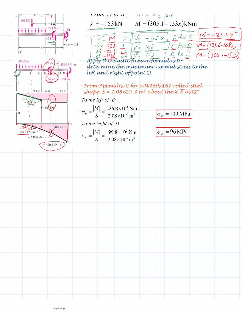
Apply the elastic flexure formulas to
determine the maximum normal stress to the
left and right of point D.
From Appendix C for a W250x167 rolled steel
shape, S = 2.08x10⁻³ m3
about the X-X axis.
chapter 5 Page 2

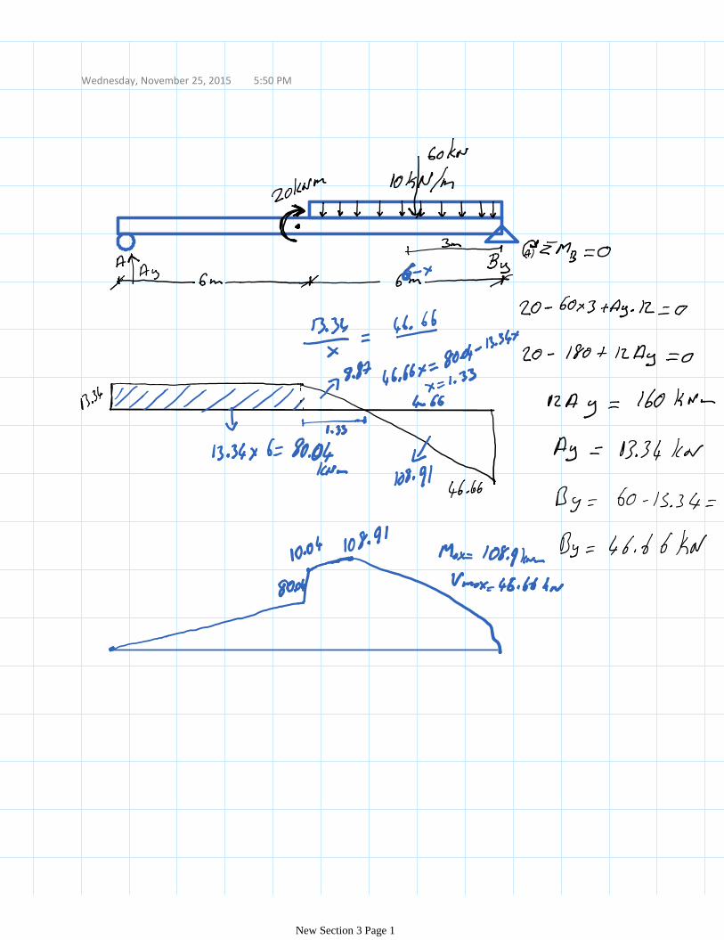
Draw the shear and bending moment
diagrams for the beam and loading shown.
SOLUTION:
Taking the entire beam as a free body,
determine the reactions at A and D.
Apply the relationship between shear
and load to develop the shear diagram.
Apply the relationship between bending
moment and shear to develop the
bending moment diagram.
SOLUTION:
Taking the entire beam as a free body,
determine the reactions at A and D.
Apply the relationship between bending
moment and shear to develop the bending
moment diagram.
bending moment at A and E is zero
bending moment variation between A, B, C
Sample Problem
Saturday, October 24, 2015 11:41 PM
chapter 5 Page 1

bending moment at A and E is zero
bending moment variation between A, B, C
and D is linear
bending moment variation between D and
E is quadratic
net change in bending moment is equal to
areas under shear distribution segments
total of all bending moment changes across
the beam should be zero
chapter 5 Page 2

Draw the shear and bending moment
diagrams for the beam and loading
shown.
SOLUTION:
Taking the entire beam as a free body, determine the reactions at C.
Apply the relationship between shear and load to develop the shear
diagram.
Apply the relationship between bending moment and shear to develop
the bending moment diagram.
Apply the relationship between bending
moment and shear to develop the bending
Sample Problem
Saturday, October 24, 2015 11:49 PM
chapter 5 Page 1

Apply the relationship between bending
moment and shear to develop the bending
moment diagram.
Results at C are compatible with free-body analysis
chapter 5 Page 2

Exp video 2Monday, November 16, 2015 7:06 PM
chapter 5 Page 1
Wednesday, November 25, 2015 5:50 PM
New Section 3 Page 1