radiation lot acceptance testing (rlat) of the … · radiation lot acceptance ... 12 units total,...
TRANSCRIPT
RLAT Report 10-041 100505 R1.0
An ISO 9001:2008 and DSCC Certified Company
1
Radiation Assured Devices5017 N. 30th Street Colorado Springs, CO 80919 (719) 531-0800
Radiation Lot Acceptance Testing (RLAT) of the RH1016MW UltraFast Precision Comparator for Linear Technology
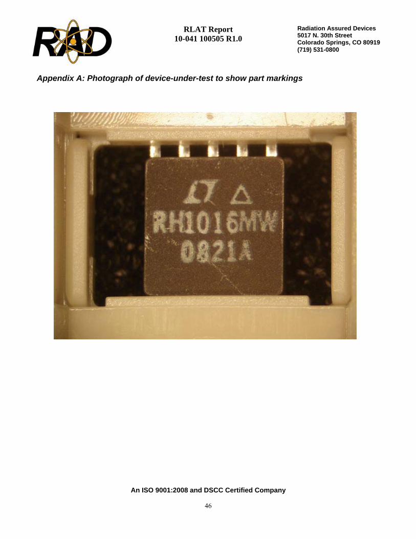
Customer: Linear Technology (PO 55080L) RAD Job Number: 10-041 Part Type Tested: Linear Technology RH1016MW UltraFast Precision Comparator Commercial Part Number: RH1016MW Traceability Information: Lot Date Code: 0821A, Fab Lot# WD003520.2, Wafer 2, Assembly Lot# 482911.1. Information obtained from Linear Technology PO#55080L. See photograph of unit under test in Appendix A. Quantity of Units: 12 units total, 5 units for biased irradiation, 5 units for unbiased irradiation (all pins tied to ground) and 2 control units. Serial numbers 731, 732, 734, 735, and 764 were biased during irradiation. Serial numbers 765 to 767, 769, and 770 were unbiased during irradiation (all pins tied to ground). Serial numbers 771 and 772 were used as controls. See Appendix B for the radiation bias connection table. Pre-Irradiation Burn-In: Burn-In performed by Linear Technology prior to receipt by RAD. TID Dose Rate and Test Increments: 50-300rad(Si)/s with readings at pre-irradiation, 20, 50, 100, and 200krad(Si). TID Overtest and Post-Irradiation Anneal: No overtest. 24-hour room temperature anneal followed by a 168-hour 100°C anneal. Both anneals shall be performed in the same electrical bias condition as the irradiations. Electrical measurements shall be made following each anneal increment. TID Test Standard: MIL-STD-883G, Method 1019.7, Condition A TID Electrical Test Conditions: Pre-irradiation, and within one hour following each radiation exposure. Test Programs: RH1016W.SRC Test Hardware: LTS2020 Tester, 2101 Family Board, 0608 Fixture, and RH1016 BGSS-100116 DUT Board. Facility and Radiation Source: Radiation Assured Devices Longmire Laboratories, Colorado Springs, CO using the JLSA 81-24 high dose rate Co60 source. Dosimetry performed by CaF2 TLDs traceable to NIST. RAD’s dosimetry has been audited by DSCC and RAD has been awarded Laboratory Suitability for MIL-STD-750 TM 1019.5. Irradiation and Test Temperature: Ambient room temperature for irradiation and test controlled to 24°C±6°C per MIL-STD-883.
RLAT Result: PASSED the RLAT to maximum dose level of 200krad(Si) with all units-under-test remaining within their respective datasheet
specifications

RLAT Report 10-041 100505 R1.0
An ISO 9001:2008 and DSCC Certified Company
2
Radiation Assured Devices5017 N. 30th Street Colorado Springs, CO 80919 (719) 531-0800
1.0. Overview and Background It is well known that total dose ionizing radiation can cause parametric degradation and ultimately functional failure in electronic devices. The damage occurs via electron-hole pair production, transport and trapping in the dielectric and interface regions. In discrete devices the bulk of the damage is frequently manifested as a reduction in the gain and/or breakdown voltage of the device. The damage will usually anneal with time following the end of the radiation exposure. Due to this annealing, and to ensure a worst-case test condition MIL-STD-883 TM1019.7 calls out a dose rate of 50 to 300rad(Si)/s as Condition A and further specifies that the time from the end of an incremental radiation exposure and electrical testing shall be 1-hour or less and the total time from the end of one incremental irradiation to the beginning of the next incremental radiation step should be 2-hours or less. The work described in this report was performed to meet MIL-STD-883 TM1019.7 Condition A. 2.0. Radiation Test Apparatus The total ionizing dose testing described in this final report was performed using the facilities at Radiation Assured Devices’ Longmire Laboratories in Colorado Springs, CO. The high dose rate total ionizing dose (TID) source is a JLSA 84-21 irradiator modified to provide a panoramic exposure. The Co-60 rods are held in the base of the irradiator heavily shielded by lead, during the radiation exposures the rod is raised by an electronic timer/controller and the exposure is performed in air. The dose rate for this irradiator in this configuration ranges from <1rad(Si)/s to a maximum of approximately 120rad(Si)/s, determined by the distance from the source. For high-dose rate experiments the bias boards are placed in a radial fashion equidistant from the raised Co-60 rods with the distance adjusted to provide the required dose rate. The irradiator calibration is maintained by Radiation Assured Devices Longmire Laboratories using thermoluminescent dosimeters (TLDs)) traceable to the National Institute of Standards and Technology (NIST). Figure 2.1 shows a photograph of the JLSA 81-24 Co-60 irradiator at RAD’s Longmire Laboratory facility. RAD is currently certified by the Defense Supply Center Columbus (DSCC) for Laboratory Suitability under MIL STD 750. Additional details regarding Radiation Assured Devices dosimetry for TM1019 Condition A testing are available in RAD’s report to DSCC entitled: “Dose Rate Mapping of the J.L. Shepherd and Associates Model 81 Irradiator Installed by Radiation Assured Devices”

RLAT Report 10-041 100505 R1.0
An ISO 9001:2008 and DSCC Certified Company
3
Radiation Assured Devices5017 N. 30th Street Colorado Springs, CO 80919 (719) 531-0800
Figure 2.1. Radiation Assured Devices’ high dose rate Co-60 irradiator. The dose rate is obtained by positioning the device-under-test at a fixed distance from the gamma cell. The dose rate for this irradiator varies from approximately 120rad(Si)/s close to the rods down to 1rad(Si)/s at a distance ofapproximately 2-feet.

RLAT Report 10-041 100505 R1.0
An ISO 9001:2008 and DSCC Certified Company
4
Radiation Assured Devices5017 N. 30th Street Colorado Springs, CO 80919 (719) 531-0800
3.0. Radiation Test Conditions The RH1016MW UltraFast Precision Comparator described in this final report were irradiated using a split ±5V supply and with all pins tied to ground, that is biased and unbiased. See the TID Bias Table in Appendix B for the full bias circuits. In our opinion, these bias circuits satisfy the requirements of MIL-STD-883G TM1019.7 Section 3.9.3 Bias and Loading Conditions which states “The bias applied to the test devices shall be selected to produce the greatest radiation induced damage or the worst-case damage for the intended application, if known. While maximum voltage is often worst case some bipolar linear device parameters (e.g. input bias current or maximum output load current) exhibit more degradation with 0 V bias.” Note that the determination of pass / fail for this lot is based on the response of the biased units only. The devices were irradiated to a maximum total ionizing dose level of 200krad(Si) with incremental readings at 20, 50, 100 and 200krad(Si). Electrical testing occurred within one hour following the end of each irradiation segment. For intermediate irradiations, the parts were tested and returned to total dose exposure within two hours from the end of the previous radiation increment. The TID bias board was positioned in the Co-60 cell to provide the required minimum of 50rad(Si)/s and was located inside a lead-aluminum enclosure. The lead-aluminum enclosure is required under MIL-STD-883G TM1019.7 Section 3.4 that reads as follows: “Lead/Aluminum (Pb/Al) container. Test specimens shall be enclosed in a Pb/Al container to minimize dose enhancement effects caused by low-energy, scattered radiation. A minimum of 1.5 mm Pb, surrounding an inner shield of at least 0.7 mm Al, is required. This Pb/Al container produces an approximate charged particle equilibrium for Si and for TLDs such as CaF2. The radiation field intensity shall be measured inside the Pb/Al container (1) initially, (2) when the source is changed, or (3) when the orientation or configuration of the source, container, or test-fixture is changed. This measurement shall be performed by placing a dosimeter (e.g., a TLD) in the device-irradiation container at the approximate test-device position. If it can be demonstrated that low energy scattered radiation is small enough that it will not cause dosimetry errors due to dose enhancement, the Pb/Al container may be omitted”. The final dose rate within the high dose rate lead-aluminum enclosure was determined based on TLD dosimetry measurements (see previous section). The final dose rate for this work was 52.0rad(Si)/s with a precision of ±5%.
RLAT Report 10-041 100505 R1.0
An ISO 9001:2008 and DSCC Certified Company
5
Radiation Assured Devices5017 N. 30th Street Colorado Springs, CO 80919 (719) 531-0800
4.0. Tested Parameters
During the radiation lot acceptance testing described in this report the following pre- and post-irradiation electrical parameters were measured:
1. Positive Supply Current (A) 2. Negative Supply Current (A) 3. Input Offset Voltage (V) 4. Input Offset Current (A) 5. Positive Input Bias Current (A) 6. Negative Input Bias Current (A) 7. Average Input Bias Current (A) 8. Positive PSRR (dB) 9. Negative PSRR (dB) 10. Small-Signal Voltage Gain (V/V) 11. CMRR (dB) 12. Output High Voltage IOUT=1mA - Q (V) 13. Output High Voltage IOUT=10mA - Q (V) 14. Output Low Voltage ISINK=4mA - Q (V) 15. Output High Voltage IOUT=1mA - Q# (V) 16. Output High Voltage IOUT=10mA - Q# (V) 17. Output Low Voltage ISINK=4mA - Q# (V) 18. LATCH Pin Input Voltage Threshold (V) 19. LATCH Pin Current (A)
Appendix C details the measured parameters, test conditions, pre-irradiation specification and measurement resolution for each of the measurements.
The parametric data was obtained as read and record and all the raw data plus an attributes summary are contained in a separate Excel file. The attributes data contains the average, standard deviation and the average with the KTL values applied. The KTL value used in this work is 2.742 per MIL-HDBK-814 using one sided tolerance limits of 90/90 and a 5-piece sample size. The 90/90 KTL values were selected to match the statistical levels specified in the MIL-PRF-38535 sampling plan for the qualification of a radiation hardness assured (RHA) component. Note that the following criteria must be met for a device to pass the RLAT: following the radiation exposure each of the 5 pieces irradiated under electrical bias shall pass the specification value. The units irradiated without electrical bias and the KTL statistics are included in this report for reference only. If any of the 5 pieces irradiated under electrical bias exceed the datasheet specifications, then the lot could be logged as a failure.

RLAT Report 10-041 100505 R1.0
An ISO 9001:2008 and DSCC Certified Company
6
Radiation Assured Devices5017 N. 30th Street Colorado Springs, CO 80919 (719) 531-0800
5.0. Total Ionizing Dose Test Results
Based on the criterion described above, the RH1016MW UltraFast Precision Comparator (from the lot date code/traceability information identified on the first page of this test report) PASSED the RLAT to the maximum dose level of 200krad(Si) with all measured parameters remaining within their respective datasheet specification values. Note that the data for the units-under-test irradiated in the unbiased condition and the KTL statistics presented in this report are for reference only and are not used for the determination of “PASS/FAIL” for the lot. Figures 5.1 through 5.19 show plots of all the measured parameters versus total ionizing dose while Tables 5.1 – 5.19 show the corresponding raw data for each of these parameters. In the data plots the solid diamonds are the average of the measured data points for the sample irradiated under electrical bias while the shaded diamonds are the average of the measured data points for the units irradiated with all pins tied to ground. The black lines (solid or dashed) are the average of the data points after application of the KTL statistics on the sample irradiated in the biased condition while the shaded lines (solid or dashed) are the average of the data points after application of the KTL statistics on the sample irradiated in the unbiased condition. The red dotted line(s) are the pre- and/or post-irradiation minimum and/or maximum specification value as defined in the datasheet and/or test plan. The control units, as expected, show no significant changes to any of the parameters. Therefore we can conclude that the electrical testing remained in control throughout the duration of the tests and the observed degradation was due to the radiation exposure.

RLAT Report 10-041 100505 R1.0
An ISO 9001:2008 and DSCC Certified Company
7
Radiation Assured Devices5017 N. 30th Street Colorado Springs, CO 80919 (719) 531-0800
2.00E-02
2.20E-02
2.40E-02
2.60E-02
2.80E-02
3.00E-02
3.20E-02
3.40E-02
3.60E-02
0 50 100 150 200
Total Dose (krad(Si))
Posi
tive
Supp
ly C
urre
nt (A
)
Average Biased Average Un-Biased Ps90%/90% (+KTL) Biased
Ps90%/90% (+KTL) Un-Biased Specif ication MAX
Figure 5.1. Plot of Positive Supply Current (A) versus total dose. The solid diamonds are the average of themeasured data points for the samples irradiated under electrical bias while the shaded diamonds are theaverage of the measured data points for the samples irradiated with all pins tied to ground. The black lines(solid and/or dashed) are the average of the data points after application of the KTL statistics on the samplesirradiated under electrical bias while the gray lines (solid and/or dashed) are the average of the data points afterapplication of the KTL statistics on the samples irradiated in the unbiased condition. The red dotted line(s) arethe pre- and/or post-irradiation minimum and/or maximum specification value as defined in the datasheetand/or test plan.

RLAT Report 10-041 100505 R1.0
An ISO 9001:2008 and DSCC Certified Company
8
Radiation Assured Devices5017 N. 30th Street Colorado Springs, CO 80919 (719) 531-0800
Table 5.1. Raw data for Positive Supply Current (A) versus total dose, including the statisticalanalysis, specification and the status of the testing (pass/fail).
Positive Supply Current (A)
Device 0 20 50 100 200731 2.88E-02 2.85E-02 2.85E-02 2.84E-02 2.83E-02732 2.87E-02 2.84E-02 2.84E-02 2.84E-02 2.82E-02734 2.93E-02 2.90E-02 2.89E-02 2.89E-02 2.87E-02735 2.81E-02 2.77E-02 2.77E-02 2.77E-02 2.77E-02764 2.89E-02 2.85E-02 2.86E-02 2.86E-02 2.83E-02765 2.78E-02 2.75E-02 2.75E-02 2.73E-02 2.71E-02766 2.96E-02 2.92E-02 2.91E-02 2.91E-02 2.87E-02767 2.84E-02 2.81E-02 2.80E-02 2.78E-02 2.75E-02769 2.75E-02 2.71E-02 2.71E-02 2.70E-02 2.68E-02770 2.79E-02 2.75E-02 2.75E-02 2.74E-02 2.71E-02771 2.88E-02 2.85E-02 2.85E-02 2.84E-02 2.85E-02772 2.79E-02 2.76E-02 2.76E-02 2.76E-02 2.76E-02
Biased StatisticsAverage Biased 2.88E-02 2.84E-02 2.84E-02 2.84E-02 2.82E-02Std Dev Biased 4.53E-04 4.68E-04 4.55E-04 4.49E-04 3.74E-04Ps90%/90% (+KTL) Biased 3.00E-02 2.97E-02 2.97E-02 2.96E-02 2.93E-02Ps90%/90% (-KTL) Biased 2.75E-02 2.71E-02 2.72E-02 2.71E-02 2.72E-02Un-Biased StatisticsAverage Un-Biased 2.82E-02 2.79E-02 2.78E-02 2.77E-02 2.74E-02Std Dev Un-Biased 7.91E-04 8.16E-04 7.76E-04 8.25E-04 7.41E-04Ps90%/90% (+KTL) Un-Biased 3.04E-02 3.01E-02 3.00E-02 3.00E-02 2.95E-02Ps90%/90% (-KTL) Un-Biased 2.61E-02 2.56E-02 2.57E-02 2.54E-02 2.54E-02Specification MAX 3.50E-02 3.50E-02 3.50E-02 3.50E-02 3.50E-02Status PASS PASS PASS PASS PASS
Total Dose (krad(Si))
RLAT Report 10-041 100505 R1.0
An ISO 9001:2008 and DSCC Certified Company
9
Radiation Assured Devices5017 N. 30th Street Colorado Springs, CO 80919 (719) 531-0800
-5.50E-03
-5.00E-03
-4.50E-03
-4.00E-03
-3.50E-03
-3.00E-03
-2.50E-03
-2.00E-03
0 50 100 150 200
Total Dose (krad(Si))
Neg
ativ
e Su
pply
Cur
rent
(A)
Average Biased Average Un-Biased Ps90%/90% (-KTL) Biased
Ps90%/90% (-KTL) Un-Biased Specif ication MIN
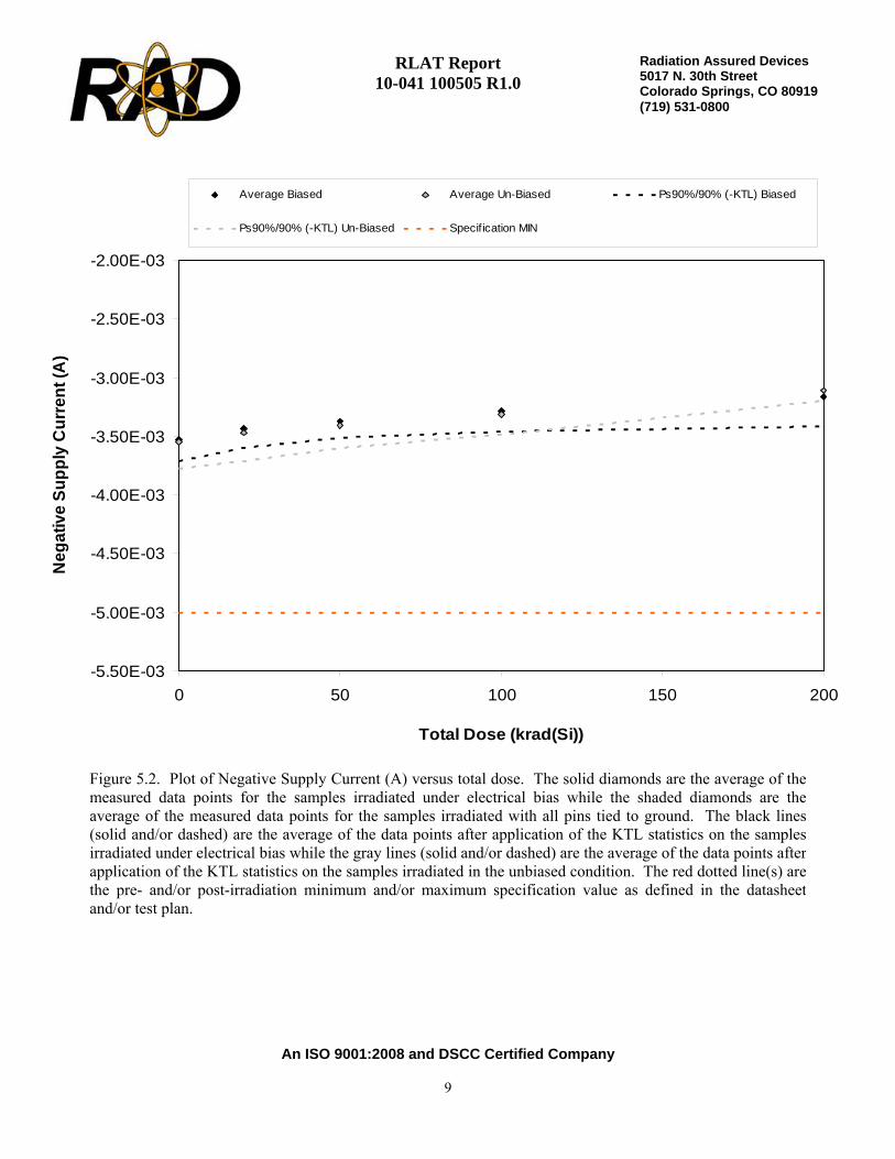
Figure 5.2. Plot of Negative Supply Current (A) versus total dose. The solid diamonds are the average of themeasured data points for the samples irradiated under electrical bias while the shaded diamonds are theaverage of the measured data points for the samples irradiated with all pins tied to ground. The black lines(solid and/or dashed) are the average of the data points after application of the KTL statistics on the samplesirradiated under electrical bias while the gray lines (solid and/or dashed) are the average of the data points afterapplication of the KTL statistics on the samples irradiated in the unbiased condition. The red dotted line(s) arethe pre- and/or post-irradiation minimum and/or maximum specification value as defined in the datasheetand/or test plan.

RLAT Report 10-041 100505 R1.0
An ISO 9001:2008 and DSCC Certified Company
10
Radiation Assured Devices5017 N. 30th Street Colorado Springs, CO 80919 (719) 531-0800
Table 5.2. Raw data for Negative Supply Current (A) versus total dose, including thestatistical analysis, specification and the status of the testing (pass/fail).
Negative Supply Current (A)
Device 0 20 50 100 200731 -3.47E-03 -3.39E-03 -3.39E-03 -3.31E-03 -3.22E-03732 -3.56E-03 -3.48E-03 -3.41E-03 -3.31E-03 -3.23E-03734 -3.57E-03 -3.46E-03 -3.35E-03 -3.22E-03 -3.00E-03735 -3.45E-03 -3.34E-03 -3.30E-03 -3.22E-03 -3.15E-03764 -3.60E-03 -3.48E-03 -3.42E-03 -3.36E-03 -3.19E-03765 -3.44E-03 -3.37E-03 -3.34E-03 -3.27E-03 -3.15E-03766 -3.64E-03 -3.56E-03 -3.49E-03 -3.41E-03 -3.13E-03767 -3.59E-03 -3.54E-03 -3.45E-03 -3.28E-03 -3.07E-03769 -3.49E-03 -3.39E-03 -3.32E-03 -3.25E-03 -3.11E-03770 -3.58E-03 -3.49E-03 -3.41E-03 -3.33E-03 -3.10E-03771 -3.64E-03 -3.61E-03 -3.61E-03 -3.63E-03 -3.63E-03772 -3.53E-03 -3.51E-03 -3.50E-03 -3.50E-03 -3.52E-03
Biased StatisticsAverage Biased -3.53E-03 -3.43E-03 -3.37E-03 -3.28E-03 -3.16E-03Std Dev Biased 6.60E-05 6.24E-05 4.93E-05 6.19E-05 9.36E-05Ps90%/90% (+KTL) Biased -3.35E-03 -3.26E-03 -3.24E-03 -3.11E-03 -2.90E-03Ps90%/90% (-KTL) Biased -3.71E-03 -3.60E-03 -3.51E-03 -3.45E-03 -3.41E-03Un-Biased StatisticsAverage Un-Biased -3.55E-03 -3.47E-03 -3.40E-03 -3.31E-03 -3.11E-03Std Dev Un-Biased 8.11E-05 8.63E-05 7.19E-05 6.42E-05 3.03E-05Ps90%/90% (+KTL) Un-Biased -3.33E-03 -3.23E-03 -3.20E-03 -3.13E-03 -3.03E-03Ps90%/90% (-KTL) Un-Biased -3.77E-03 -3.71E-03 -3.60E-03 -3.48E-03 -3.20E-03Specification MIN -5.00E-03 -5.00E-03 -5.00E-03 -5.00E-03 -5.00E-03Status PASS PASS PASS PASS PASS
Total Dose (krad(Si))
RLAT Report 10-041 100505 R1.0
An ISO 9001:2008 and DSCC Certified Company
11
Radiation Assured Devices5017 N. 30th Street Colorado Springs, CO 80919 (719) 531-0800
-8.00E-03
-6.00E-03
-4.00E-03
-2.00E-03
0.00E+00
2.00E-03
4.00E-03
6.00E-03
8.00E-03
0 50 100 150 200
Total Dose (krad(Si))
Inpu
t Offs
et V
olta
ge (V
)
Average Biased Average Un-Biased Ps90%/90% (-KTL) Biased
Ps90%/90% (-KTL) Un-Biased Ps90%/90% (+KTL) Biased Ps90%/90% (+KTL) Un-Biased
Specif ication MIN Specif ication MAX
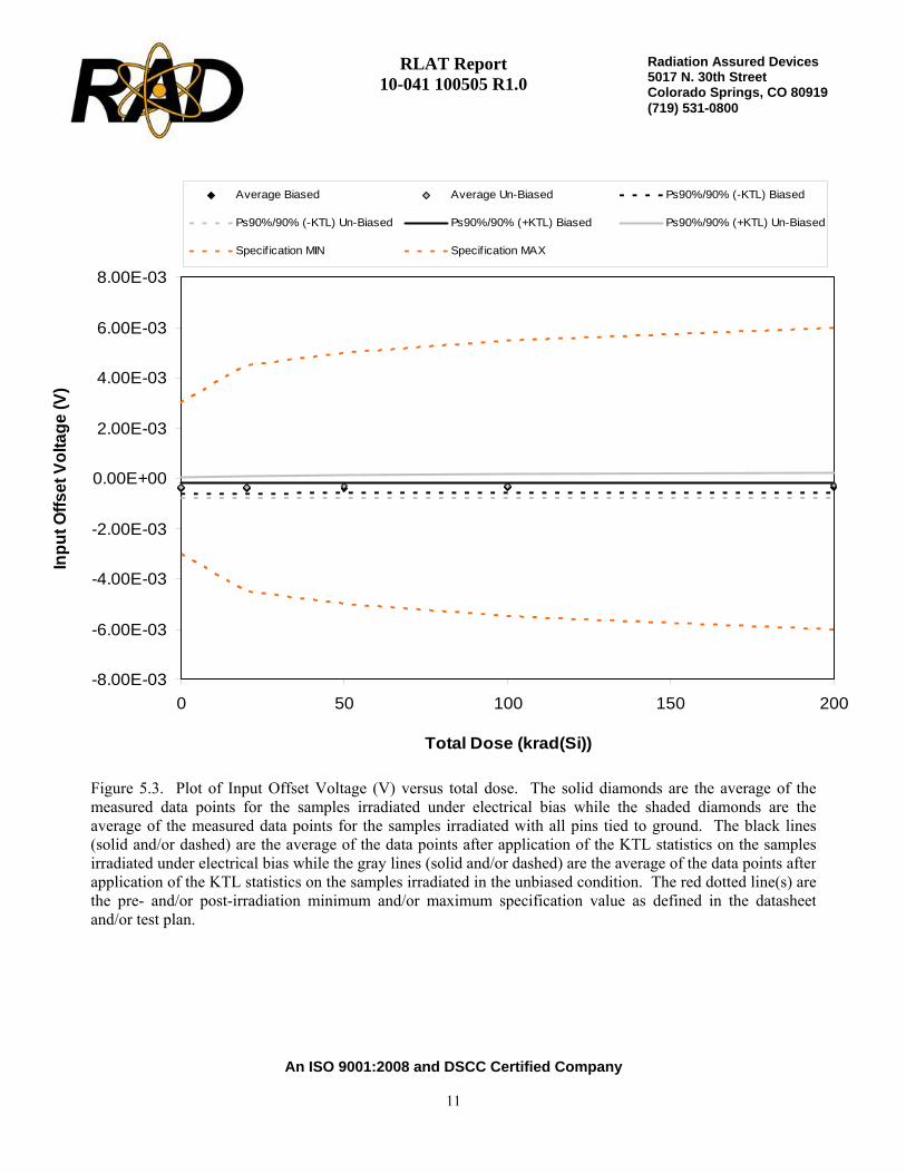
Figure 5.3. Plot of Input Offset Voltage (V) versus total dose. The solid diamonds are the average of themeasured data points for the samples irradiated under electrical bias while the shaded diamonds are theaverage of the measured data points for the samples irradiated with all pins tied to ground. The black lines(solid and/or dashed) are the average of the data points after application of the KTL statistics on the samplesirradiated under electrical bias while the gray lines (solid and/or dashed) are the average of the data points afterapplication of the KTL statistics on the samples irradiated in the unbiased condition. The red dotted line(s) arethe pre- and/or post-irradiation minimum and/or maximum specification value as defined in the datasheetand/or test plan.
RLAT Report 10-041 100505 R1.0
An ISO 9001:2008 and DSCC Certified Company
12
Radiation Assured Devices5017 N. 30th Street Colorado Springs, CO 80919 (719) 531-0800
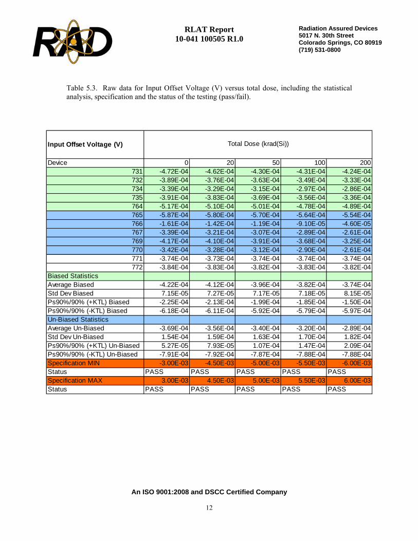
Table 5.3. Raw data for Input Offset Voltage (V) versus total dose, including the statisticalanalysis, specification and the status of the testing (pass/fail).
Input Offset Voltage (V)
Device 0 20 50 100 200731 -4.72E-04 -4.62E-04 -4.30E-04 -4.31E-04 -4.24E-04732 -3.89E-04 -3.76E-04 -3.63E-04 -3.49E-04 -3.33E-04734 -3.39E-04 -3.29E-04 -3.15E-04 -2.97E-04 -2.86E-04735 -3.91E-04 -3.83E-04 -3.69E-04 -3.56E-04 -3.36E-04764 -5.17E-04 -5.10E-04 -5.01E-04 -4.78E-04 -4.89E-04765 -5.87E-04 -5.80E-04 -5.70E-04 -5.64E-04 -5.54E-04766 -1.61E-04 -1.42E-04 -1.19E-04 -9.10E-05 -4.60E-05767 -3.39E-04 -3.21E-04 -3.07E-04 -2.89E-04 -2.61E-04769 -4.17E-04 -4.10E-04 -3.91E-04 -3.68E-04 -3.25E-04770 -3.42E-04 -3.28E-04 -3.12E-04 -2.90E-04 -2.61E-04771 -3.74E-04 -3.73E-04 -3.74E-04 -3.74E-04 -3.74E-04772 -3.84E-04 -3.83E-04 -3.82E-04 -3.83E-04 -3.82E-04
Biased StatisticsAverage Biased -4.22E-04 -4.12E-04 -3.96E-04 -3.82E-04 -3.74E-04Std Dev Biased 7.15E-05 7.27E-05 7.17E-05 7.18E-05 8.15E-05Ps90%/90% (+KTL) Biased -2.25E-04 -2.13E-04 -1.99E-04 -1.85E-04 -1.50E-04Ps90%/90% (-KTL) Biased -6.18E-04 -6.11E-04 -5.92E-04 -5.79E-04 -5.97E-04Un-Biased StatisticsAverage Un-Biased -3.69E-04 -3.56E-04 -3.40E-04 -3.20E-04 -2.89E-04Std Dev Un-Biased 1.54E-04 1.59E-04 1.63E-04 1.70E-04 1.82E-04Ps90%/90% (+KTL) Un-Biased 5.27E-05 7.93E-05 1.07E-04 1.47E-04 2.09E-04Ps90%/90% (-KTL) Un-Biased -7.91E-04 -7.92E-04 -7.87E-04 -7.88E-04 -7.88E-04Specification MIN -3.00E-03 -4.50E-03 -5.00E-03 -5.50E-03 -6.00E-03Status PASS PASS PASS PASS PASSSpecification MAX 3.00E-03 4.50E-03 5.00E-03 5.50E-03 6.00E-03Status PASS PASS PASS PASS PASS
Total Dose (krad(Si))

RLAT Report 10-041 100505 R1.0
An ISO 9001:2008 and DSCC Certified Company
13
Radiation Assured Devices5017 N. 30th Street Colorado Springs, CO 80919 (719) 531-0800
-1.50E-05
-1.00E-05
-5.00E-06
0.00E+00
5.00E-06
1.00E-05
1.50E-05
0 50 100 150 200
Total Dose (krad(Si))
Inpu
t Offs
et C
urre
nt (A
)
Average Biased Average Un-Biased Ps90%/90% (-KTL) Biased
Ps90%/90% (-KTL) Un-Biased Ps90%/90% (+KTL) Biased Ps90%/90% (+KTL) Un-Biased
Specif ication MIN Specif ication MAX
Figure 5.4. Plot of Input Offset Current (A) versus total dose. The solid diamonds are the average of themeasured data points for the samples irradiated under electrical bias while the shaded diamonds are theaverage of the measured data points for the samples irradiated with all pins tied to ground. The black lines(solid and/or dashed) are the average of the data points after application of the KTL statistics on the samplesirradiated under electrical bias while the gray lines (solid and/or dashed) are the average of the data points afterapplication of the KTL statistics on the samples irradiated in the unbiased condition. The red dotted line(s) arethe pre- and/or post-irradiation minimum and/or maximum specification value as defined in the datasheetand/or test plan.

RLAT Report 10-041 100505 R1.0
An ISO 9001:2008 and DSCC Certified Company
14
Radiation Assured Devices5017 N. 30th Street Colorado Springs, CO 80919 (719) 531-0800
Table 5.4. Raw data for Input Offset Current (A) versus total dose, including the statisticalanalysis, specification and the status of the testing (pass/fail).
Input Offset Current (A)
Device 0 20 50 100 200731 -1.45E-07 -6.15E-07 -1.60E-06 -3.21E-06 -4.81E-06732 -7.00E-09 -4.08E-07 -1.50E-06 -2.92E-06 -4.33E-06734 -1.80E-08 -4.54E-07 -1.50E-06 -2.98E-06 -4.48E-06735 -2.78E-07 -7.65E-07 -1.92E-06 -3.45E-06 -5.07E-06764 -3.92E-07 -7.69E-07 -1.73E-06 -2.89E-06 -4.41E-06765 -4.10E-07 -4.34E-07 -4.55E-07 -4.73E-07 -5.77E-07766 -5.20E-08 -5.30E-08 -6.20E-08 -7.20E-08 -7.00E-08767 2.00E-08 1.20E-08 2.70E-08 4.40E-08 2.30E-08769 -8.90E-08 -1.00E-07 -9.20E-08 -1.02E-07 -1.07E-07770 -3.00E-08 -3.30E-08 -4.40E-08 -3.90E-08 -3.60E-08771 -1.15E-07 -1.23E-07 -1.20E-07 -1.21E-07 -1.21E-07772 -1.04E-07 -1.03E-07 -1.05E-07 -1.05E-07 -1.11E-07
Biased StatisticsAverage Biased -1.68E-07 -6.02E-07 -1.65E-06 -3.09E-06 -4.62E-06Std Dev Biased 1.67E-07 1.69E-07 1.80E-07 2.36E-07 3.12E-07Ps90%/90% (+KTL) Biased 2.89E-07 -1.39E-07 -1.16E-06 -2.44E-06 -3.77E-06Ps90%/90% (-KTL) Biased -6.25E-07 -1.07E-06 -2.15E-06 -3.74E-06 -5.48E-06Un-Biased StatisticsAverage Un-Biased -1.12E-07 -1.22E-07 -1.25E-07 -1.28E-07 -1.53E-07Std Dev Un-Biased 1.71E-07 1.79E-07 1.89E-07 2.00E-07 2.42E-07Ps90%/90% (+KTL) Un-Biased 3.57E-07 3.70E-07 3.94E-07 4.21E-07 5.09E-07Ps90%/90% (-KTL) Un-Biased -5.81E-07 -6.13E-07 -6.45E-07 -6.77E-07 -8.16E-07Specification MIN -1.00E-06 -2.50E-06 -5.00E-06 -8.00E-06 -1.20E-05Status PASS PASS PASS PASS PASSSpecification MAX 1.00E-06 2.50E-06 5.00E-06 8.00E-06 1.20E-05Status PASS PASS PASS PASS PASS
Total Dose (krad(Si))

RLAT Report 10-041 100505 R1.0
An ISO 9001:2008 and DSCC Certified Company
15
Radiation Assured Devices5017 N. 30th Street Colorado Springs, CO 80919 (719) 531-0800
-2.50E-05
-2.00E-05
-1.50E-05
-1.00E-05
-5.00E-06
0.00E+00
5.00E-06
1.00E-05
1.50E-05
2.00E-05
2.50E-05
0 50 100 150 200
Total Dose (krad(Si))
Posi
tive
Inpu
t Bia
s C
urre
nt (A
)
Average Biased Average Un-Biased Ps90%/90% (-KTL) Biased
Ps90%/90% (-KTL) Un-Biased Ps90%/90% (+KTL) Biased Ps90%/90% (+KTL) Un-Biased
Specif ication MIN Specif ication MAX
Figure 5.5. Plot of Positive Input Bias Current (A) versus total dose. The solid diamonds are the average ofthe measured data points for the samples irradiated under electrical bias while the shaded diamonds are theaverage of the measured data points for the samples irradiated with all pins tied to ground. The black lines(solid and/or dashed) are the average of the data points after application of the KTL statistics on the samplesirradiated under electrical bias while the gray lines (solid and/or dashed) are the average of the data points afterapplication of the KTL statistics on the samples irradiated in the unbiased condition. The red dotted line(s) arethe pre- and/or post-irradiation minimum and/or maximum specification value as defined in the datasheetand/or test plan.

RLAT Report 10-041 100505 R1.0
An ISO 9001:2008 and DSCC Certified Company
16
Radiation Assured Devices5017 N. 30th Street Colorado Springs, CO 80919 (719) 531-0800
Table 5.5. Raw data for Positive Input Bias Current (A) versus total dose, including thestatistical analysis, specification and the status of the testing (pass/fail).
Positive Input Bias Current (A)
Device 0 20 50 100 200731 6.76E-06 6.92E-06 7.12E-06 7.39E-06 7.76E-06732 5.38E-06 5.54E-06 5.76E-06 6.03E-06 6.43E-06734 6.45E-06 6.61E-06 6.82E-06 7.09E-06 7.41E-06735 6.31E-06 6.47E-06 6.68E-06 6.96E-06 7.36E-06764 4.09E-06 4.24E-06 4.44E-06 4.66E-06 5.06E-06765 6.34E-06 6.66E-06 7.18E-06 7.96E-06 8.99E-06766 3.97E-06 4.22E-06 4.71E-06 5.36E-06 6.43E-06767 3.11E-06 3.31E-06 3.73E-06 4.35E-06 5.19E-06769 4.04E-06 4.36E-06 4.88E-06 5.65E-06 6.79E-06770 3.05E-06 3.28E-06 3.71E-06 4.35E-06 5.28E-06771 4.00E-06 3.99E-06 4.00E-06 4.00E-06 3.99E-06772 3.50E-06 3.50E-06 3.50E-06 3.50E-06 3.49E-06
Biased StatisticsAverage Biased 5.80E-06 5.95E-06 6.16E-06 6.43E-06 6.80E-06Std Dev Biased 1.08E-06 1.09E-06 1.09E-06 1.11E-06 1.09E-06Ps90%/90% (+KTL) Biased 8.77E-06 8.94E-06 9.15E-06 9.47E-06 9.80E-06Ps90%/90% (-KTL) Biased 2.83E-06 2.97E-06 3.18E-06 3.39E-06 3.81E-06Un-Biased StatisticsAverage Un-Biased 4.10E-06 4.37E-06 4.84E-06 5.53E-06 6.54E-06Std Dev Un-Biased 1.34E-06 1.37E-06 1.42E-06 1.48E-06 1.54E-06Ps90%/90% (+KTL) Un-Biased 7.77E-06 8.13E-06 8.73E-06 9.59E-06 1.08E-05Ps90%/90% (-KTL) Un-Biased 4.36E-07 5.99E-07 9.53E-07 1.48E-06 2.31E-06Specification MIN -1.00E-05 -1.20E-05 -1.40E-05 -1.70E-05 -2.00E-05Status PASS PASS PASS PASS PASSSpecification MAX 1.00E-05 1.20E-05 1.40E-05 1.70E-05 2.00E-05Status PASS PASS PASS PASS PASS
Total Dose (krad(Si))
RLAT Report 10-041 100505 R1.0
An ISO 9001:2008 and DSCC Certified Company
17
Radiation Assured Devices5017 N. 30th Street Colorado Springs, CO 80919 (719) 531-0800
-2.50E-05
-2.00E-05
-1.50E-05
-1.00E-05
-5.00E-06
0.00E+00
5.00E-06
1.00E-05
1.50E-05
2.00E-05
2.50E-05
0 50 100 150 200
Total Dose (krad(Si))
Neg
ativ
e In
put B
ias
Cur
rent
(A)
Average Biased Average Un-Biased Ps90%/90% (-KTL) Biased
Ps90%/90% (-KTL) Un-Biased Ps90%/90% (+KTL) Biased Ps90%/90% (+KTL) Un-Biased
Specif ication MIN Specif ication MAX
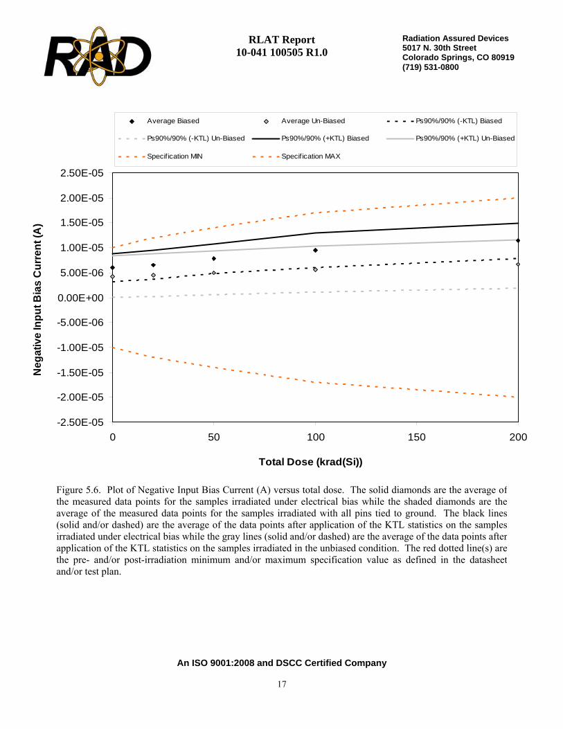
Figure 5.6. Plot of Negative Input Bias Current (A) versus total dose. The solid diamonds are the average ofthe measured data points for the samples irradiated under electrical bias while the shaded diamonds are theaverage of the measured data points for the samples irradiated with all pins tied to ground. The black lines(solid and/or dashed) are the average of the data points after application of the KTL statistics on the samplesirradiated under electrical bias while the gray lines (solid and/or dashed) are the average of the data points afterapplication of the KTL statistics on the samples irradiated in the unbiased condition. The red dotted line(s) arethe pre- and/or post-irradiation minimum and/or maximum specification value as defined in the datasheetand/or test plan.
RLAT Report 10-041 100505 R1.0
An ISO 9001:2008 and DSCC Certified Company
18
Radiation Assured Devices5017 N. 30th Street Colorado Springs, CO 80919 (719) 531-0800
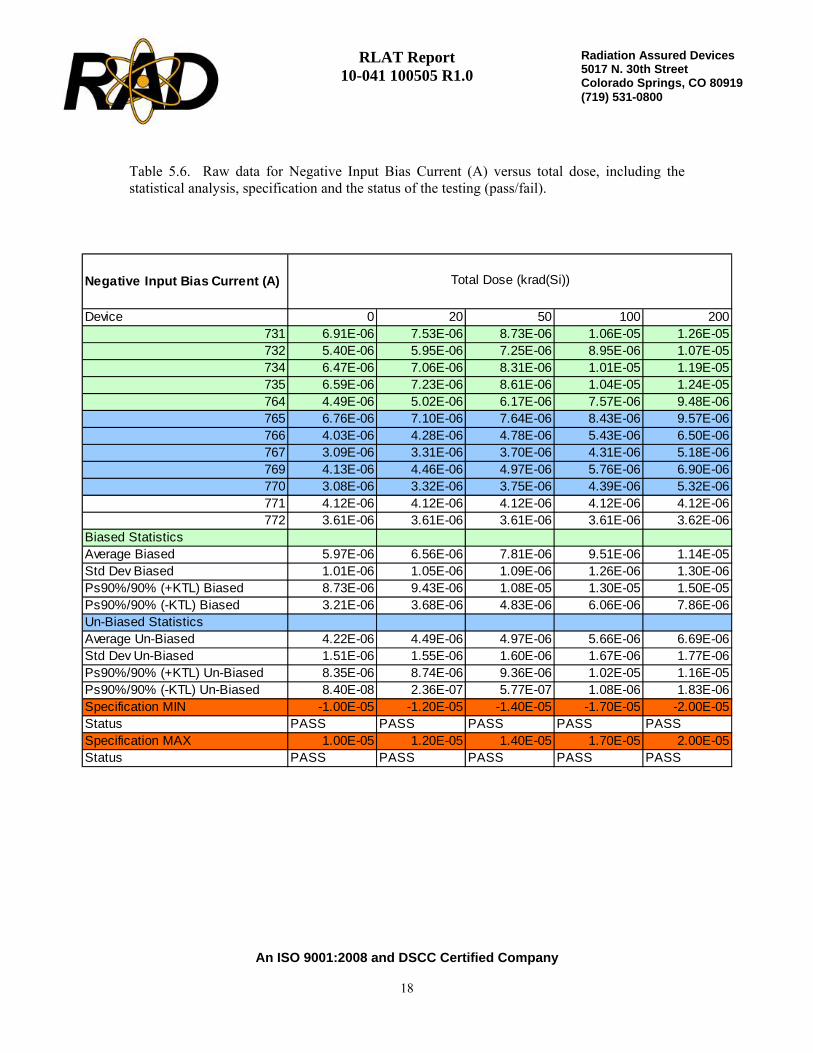
Table 5.6. Raw data for Negative Input Bias Current (A) versus total dose, including thestatistical analysis, specification and the status of the testing (pass/fail).
Negative Input Bias Current (A)
Device 0 20 50 100 200731 6.91E-06 7.53E-06 8.73E-06 1.06E-05 1.26E-05732 5.40E-06 5.95E-06 7.25E-06 8.95E-06 1.07E-05734 6.47E-06 7.06E-06 8.31E-06 1.01E-05 1.19E-05735 6.59E-06 7.23E-06 8.61E-06 1.04E-05 1.24E-05764 4.49E-06 5.02E-06 6.17E-06 7.57E-06 9.48E-06765 6.76E-06 7.10E-06 7.64E-06 8.43E-06 9.57E-06766 4.03E-06 4.28E-06 4.78E-06 5.43E-06 6.50E-06767 3.09E-06 3.31E-06 3.70E-06 4.31E-06 5.18E-06769 4.13E-06 4.46E-06 4.97E-06 5.76E-06 6.90E-06770 3.08E-06 3.32E-06 3.75E-06 4.39E-06 5.32E-06771 4.12E-06 4.12E-06 4.12E-06 4.12E-06 4.12E-06772 3.61E-06 3.61E-06 3.61E-06 3.61E-06 3.62E-06
Biased StatisticsAverage Biased 5.97E-06 6.56E-06 7.81E-06 9.51E-06 1.14E-05Std Dev Biased 1.01E-06 1.05E-06 1.09E-06 1.26E-06 1.30E-06Ps90%/90% (+KTL) Biased 8.73E-06 9.43E-06 1.08E-05 1.30E-05 1.50E-05Ps90%/90% (-KTL) Biased 3.21E-06 3.68E-06 4.83E-06 6.06E-06 7.86E-06Un-Biased StatisticsAverage Un-Biased 4.22E-06 4.49E-06 4.97E-06 5.66E-06 6.69E-06Std Dev Un-Biased 1.51E-06 1.55E-06 1.60E-06 1.67E-06 1.77E-06Ps90%/90% (+KTL) Un-Biased 8.35E-06 8.74E-06 9.36E-06 1.02E-05 1.16E-05Ps90%/90% (-KTL) Un-Biased 8.40E-08 2.36E-07 5.77E-07 1.08E-06 1.83E-06Specification MIN -1.00E-05 -1.20E-05 -1.40E-05 -1.70E-05 -2.00E-05Status PASS PASS PASS PASS PASSSpecification MAX 1.00E-05 1.20E-05 1.40E-05 1.70E-05 2.00E-05Status PASS PASS PASS PASS PASS
Total Dose (krad(Si))

RLAT Report 10-041 100505 R1.0
An ISO 9001:2008 and DSCC Certified Company
19
Radiation Assured Devices5017 N. 30th Street Colorado Springs, CO 80919 (719) 531-0800
-2.50E-05
-2.00E-05
-1.50E-05
-1.00E-05
-5.00E-06
0.00E+00
5.00E-06
1.00E-05
1.50E-05
2.00E-05
2.50E-05
0 50 100 150 200
Total Dose (krad(Si))
Ave
rage
Inpu
t Bia
s C
urre
nt (A
)
Average Biased Average Un-Biased Ps90%/90% (-KTL) Biased
Ps90%/90% (-KTL) Un-Biased Ps90%/90% (+KTL) Biased Ps90%/90% (+KTL) Un-Biased
Specif ication MIN Specif ication MAX
Figure 5.7. Plot of Average Input Bias Current (A) versus total dose. The solid diamonds are the average ofthe measured data points for the samples irradiated under electrical bias while the shaded diamonds are theaverage of the measured data points for the samples irradiated with all pins tied to ground. The black lines(solid and/or dashed) are the average of the data points after application of the KTL statistics on the samplesirradiated under electrical bias while the gray lines (solid and/or dashed) are the average of the data points afterapplication of the KTL statistics on the samples irradiated in the unbiased condition. The red dotted line(s) arethe pre- and/or post-irradiation minimum and/or maximum specification value as defined in the datasheetand/or test plan.

RLAT Report 10-041 100505 R1.0
An ISO 9001:2008 and DSCC Certified Company
20
Radiation Assured Devices5017 N. 30th Street Colorado Springs, CO 80919 (719) 531-0800
Table 5.7. Raw data for Average Input Bias Current (A) versus total dose, including thestatistical analysis, specification and the status of the testing (pass/fail).
Average Input Bias Current (A)
Device 0 20 50 100 200731 6.84E-06 7.22E-06 7.93E-06 8.99E-06 1.02E-05732 5.39E-06 5.74E-06 6.50E-06 7.49E-06 8.59E-06734 6.46E-06 6.83E-06 7.56E-06 8.57E-06 9.64E-06735 6.45E-06 6.85E-06 7.64E-06 8.66E-06 9.89E-06764 4.29E-06 4.63E-06 5.31E-06 6.12E-06 7.27E-06765 6.55E-06 6.88E-06 7.41E-06 8.20E-06 9.28E-06766 4.00E-06 4.25E-06 4.74E-06 5.39E-06 6.46E-06767 3.10E-06 3.31E-06 3.72E-06 4.33E-06 5.18E-06769 4.09E-06 4.41E-06 4.92E-06 5.70E-06 6.84E-06770 3.06E-06 3.30E-06 3.73E-06 4.37E-06 5.30E-06771 4.06E-06 4.06E-06 4.06E-06 4.06E-06 4.06E-06772 3.55E-06 3.56E-06 3.55E-06 3.55E-06 3.55E-06
Biased StatisticsAverage Biased 5.89E-06 6.26E-06 6.99E-06 7.97E-06 9.11E-06Std Dev Biased 1.04E-06 1.07E-06 1.08E-06 1.18E-06 1.19E-06Ps90%/90% (+KTL) Biased 8.74E-06 9.18E-06 9.96E-06 1.12E-05 1.24E-05Ps90%/90% (-KTL) Biased 3.03E-06 3.33E-06 4.01E-06 4.73E-06 5.85E-06Un-Biased StatisticsAverage Un-Biased 4.16E-06 4.43E-06 4.90E-06 5.60E-06 6.61E-06Std Dev Un-Biased 1.42E-06 1.46E-06 1.51E-06 1.58E-06 1.66E-06Ps90%/90% (+KTL) Un-Biased 8.06E-06 8.44E-06 9.04E-06 9.92E-06 1.12E-05Ps90%/90% (-KTL) Un-Biased 2.59E-07 4.17E-07 7.66E-07 1.28E-06 2.07E-06Specification MIN -1.00E-05 -1.20E-05 -1.40E-05 -1.70E-05 -2.00E-05Status PASS PASS PASS PASS PASSSpecification MAX 1.00E-05 1.20E-05 1.40E-05 1.70E-05 2.00E-05Status PASS PASS PASS PASS PASS
Total Dose (krad(Si))
RLAT Report 10-041 100505 R1.0
An ISO 9001:2008 and DSCC Certified Company
21
Radiation Assured Devices5017 N. 30th Street Colorado Springs, CO 80919 (719) 531-0800
0.00E+00
1.00E+01
2.00E+01
3.00E+01
4.00E+01
5.00E+01
6.00E+01
7.00E+01
8.00E+01
9.00E+01
1.00E+02
0 50 100 150 200
Total Dose (krad(Si))
Posi
tive
PSR
R (d
B)
Average Biased Average Un-Biased Ps90%/90% (-KTL) Biased
Ps90%/90% (-KTL) Un-Biased Specif ication MIN
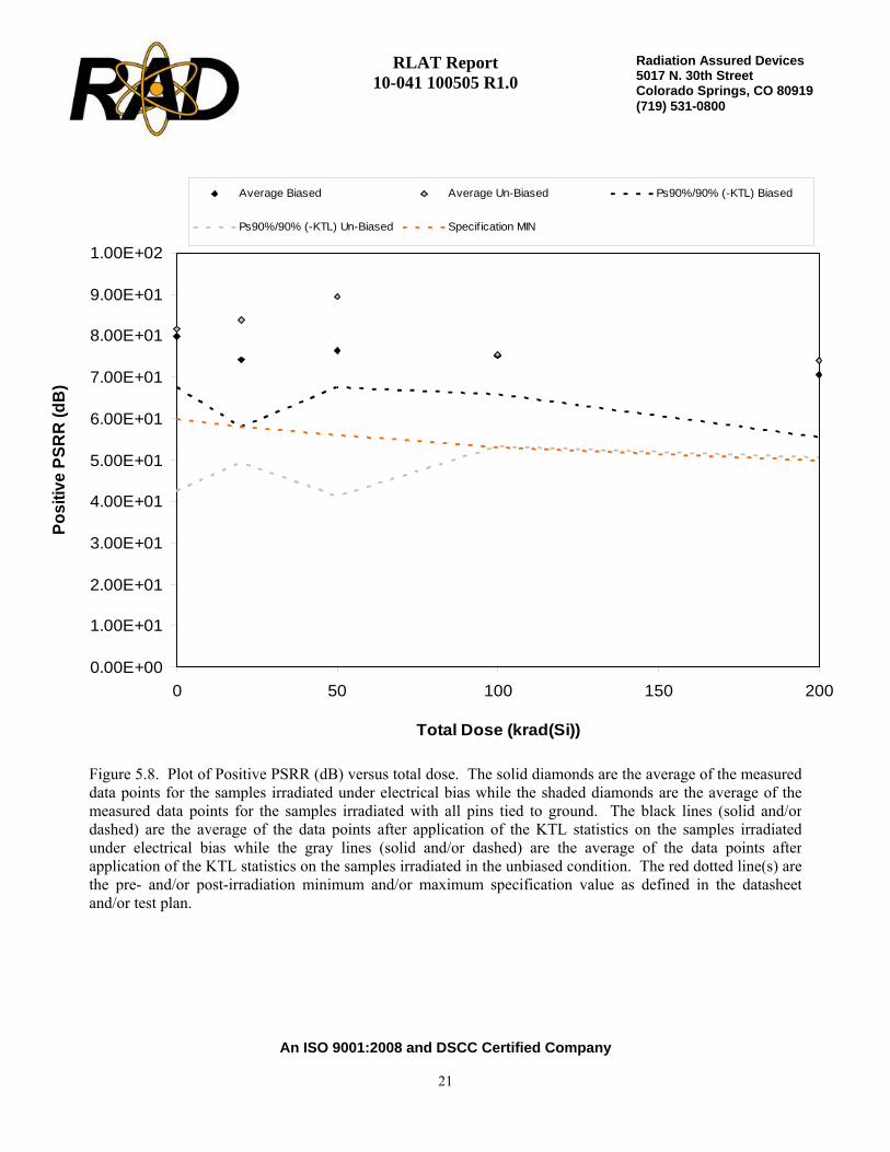
Figure 5.8. Plot of Positive PSRR (dB) versus total dose. The solid diamonds are the average of the measureddata points for the samples irradiated under electrical bias while the shaded diamonds are the average of themeasured data points for the samples irradiated with all pins tied to ground. The black lines (solid and/ordashed) are the average of the data points after application of the KTL statistics on the samples irradiatedunder electrical bias while the gray lines (solid and/or dashed) are the average of the data points afterapplication of the KTL statistics on the samples irradiated in the unbiased condition. The red dotted line(s) arethe pre- and/or post-irradiation minimum and/or maximum specification value as defined in the datasheetand/or test plan.
RLAT Report 10-041 100505 R1.0
An ISO 9001:2008 and DSCC Certified Company
22
Radiation Assured Devices5017 N. 30th Street Colorado Springs, CO 80919 (719) 531-0800
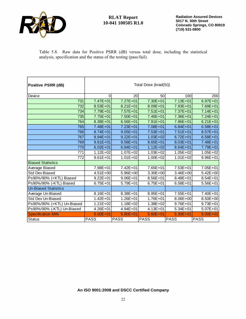
Table 5.8. Raw data for Positive PSRR (dB) versus total dose, including the statisticalanalysis, specification and the status of the testing (pass/fail).
Positive PSRR (dB)
Device 0 20 50 100 200731 7.47E+01 7.27E+01 7.30E+01 7.13E+01 6.97E+01732 8.53E+01 8.21E+01 8.09E+01 7.93E+01 7.69E+01734 7.79E+01 7.57E+01 7.51E+01 7.37E+01 7.14E+01735 7.75E+01 7.50E+01 7.46E+01 7.36E+01 7.24E+01764 8.38E+01 6.56E+01 7.91E+01 7.86E+01 6.21E+01765 7.48E+01 7.23E+01 7.08E+01 6.84E+01 6.58E+01766 8.74E+01 9.05E+01 7.53E+01 7.51E+01 8.57E+01767 8.94E+01 9.22E+01 1.03E+02 6.72E+01 6.58E+01769 9.61E+01 9.58E+01 8.65E+01 8.03E+01 7.48E+01770 6.02E+01 6.84E+01 1.12E+02 8.64E+01 7.79E+01771 1.12E+02 1.07E+02 1.03E+02 1.05E+02 1.05E+02772 9.61E+01 1.01E+02 1.00E+02 1.01E+02 9.96E+01
Biased StatisticsAverage Biased 7.98E+01 7.42E+01 7.65E+01 7.53E+01 7.05E+01Std Dev Biased 4.51E+00 5.96E+00 3.30E+00 3.46E+00 5.42E+00Ps90%/90% (+KTL) Biased 9.22E+01 9.06E+01 8.56E+01 8.48E+01 8.54E+01Ps90%/90% (-KTL) Biased 6.75E+01 5.79E+01 6.75E+01 6.58E+01 5.56E+01Un-Biased StatisticsAverage Un-Biased 8.16E+01 8.38E+01 8.95E+01 7.55E+01 7.40E+01Std Dev Un-Biased 1.42E+01 1.26E+01 1.76E+01 8.06E+00 8.50E+00Ps90%/90% (+KTL) Un-Biased 1.21E+02 1.18E+02 1.38E+02 9.76E+01 9.73E+01Ps90%/90% (-KTL) Un-Biased 4.26E+01 4.94E+01 4.13E+01 5.34E+01 5.07E+01Specification MIN 6.00E+01 5.80E+01 5.60E+01 5.30E+01 5.00E+01Status PASS PASS PASS PASS PASS
Total Dose (krad(Si))

RLAT Report 10-041 100505 R1.0
An ISO 9001:2008 and DSCC Certified Company
23
Radiation Assured Devices5017 N. 30th Street Colorado Springs, CO 80919 (719) 531-0800
5.00E+01
6.00E+01
7.00E+01
8.00E+01
9.00E+01
1.00E+02
1.10E+02
0 50 100 150 200
Total Dose (krad(Si))
Neg
ativ
e PS
RR
(dB
)
Average Biased Average Un-Biased Ps90%/90% (-KTL) Biased
Ps90%/90% (-KTL) Un-Biased Specif ication MIN
Figure 5.9. Plot of Negative PSRR (dB) versus total dose. The solid diamonds are the average of themeasured data points for the samples irradiated under electrical bias while the shaded diamonds are theaverage of the measured data points for the samples irradiated with all pins tied to ground. The black lines(solid and/or dashed) are the average of the data points after application of the KTL statistics on the samplesirradiated under electrical bias while the gray lines (solid and/or dashed) are the average of the data points afterapplication of the KTL statistics on the samples irradiated in the unbiased condition. The red dotted line(s) arethe pre- and/or post-irradiation minimum and/or maximum specification value as defined in the datasheetand/or test plan.
RLAT Report 10-041 100505 R1.0
An ISO 9001:2008 and DSCC Certified Company
24
Radiation Assured Devices5017 N. 30th Street Colorado Springs, CO 80919 (719) 531-0800
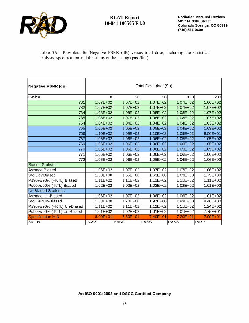
Table 5.9. Raw data for Negative PSRR (dB) versus total dose, including the statisticalanalysis, specification and the status of the testing (pass/fail).
Negative PSRR (dB)
Device 0 20 50 100 200731 1.07E+02 1.07E+02 1.07E+02 1.07E+02 1.06E+02732 1.07E+02 1.07E+02 1.07E+02 1.07E+02 1.07E+02734 1.08E+02 1.08E+02 1.08E+02 1.08E+02 1.07E+02735 1.08E+02 1.07E+02 1.08E+02 1.08E+02 1.07E+02764 1.04E+02 1.04E+02 1.04E+02 1.04E+02 1.03E+02765 1.05E+02 1.05E+02 1.05E+02 1.04E+02 1.03E+02766 1.10E+02 1.09E+02 1.10E+02 1.09E+02 8.56E+01767 1.06E+02 1.06E+02 1.06E+02 1.05E+02 1.05E+02769 1.06E+02 1.06E+02 1.06E+02 1.06E+02 1.05E+02770 1.05E+02 1.06E+02 1.06E+02 1.05E+02 1.05E+02771 1.06E+02 1.06E+02 1.06E+02 1.06E+02 1.06E+02772 1.06E+02 1.06E+02 1.06E+02 1.06E+02 1.06E+02
Biased StatisticsAverage Biased 1.06E+02 1.07E+02 1.07E+02 1.07E+02 1.06E+02Std Dev Biased 1.60E+00 1.55E+00 1.63E+00 1.63E+00 1.75E+00Ps90%/90% (+KTL) Biased 1.11E+02 1.11E+02 1.11E+02 1.11E+02 1.11E+02Ps90%/90% (-KTL) Biased 1.02E+02 1.02E+02 1.02E+02 1.02E+02 1.01E+02Un-Biased StatisticsAverage Un-Biased 1.06E+02 1.07E+02 1.06E+02 1.06E+02 1.01E+02Std Dev Un-Biased 1.83E+00 1.70E+00 1.97E+00 1.93E+00 8.46E+00Ps90%/90% (+KTL) Un-Biased 1.11E+02 1.11E+02 1.12E+02 1.11E+02 1.24E+02Ps90%/90% (-KTL) Un-Biased 1.01E+02 1.02E+02 1.01E+02 1.01E+02 7.75E+01Specification MIN 8.00E+01 7.60E+01 7.40E+01 7.20E+01 7.00E+01Status PASS PASS PASS PASS PASS
Total Dose (krad(Si))

RLAT Report 10-041 100505 R1.0
An ISO 9001:2008 and DSCC Certified Company
25
Radiation Assured Devices5017 N. 30th Street Colorado Springs, CO 80919 (719) 531-0800
0.00E+00
5.00E+02
1.00E+03
1.50E+03
2.00E+03
2.50E+03
3.00E+03
0 50 100 150 200
Total Dose (krad(Si))
Smal
l-Sig
nal V
olta
ge G
ain
(V/V
)
Average Biased Average Un-Biased Ps90%/90% (-KTL) Biased
Ps90%/90% (-KTL) Un-Biased Specif ication MIN
Figure 5.10. Plot of Small-Signal Voltage Gain (V/V) versus total dose. The solid diamonds are the averageof the measured data points for the samples irradiated under electrical bias while the shaded diamonds are theaverage of the measured data points for the samples irradiated with all pins tied to ground. The black lines(solid and/or dashed) are the average of the data points after application of the KTL statistics on the samplesirradiated under electrical bias while the gray lines (solid and/or dashed) are the average of the data points afterapplication of the KTL statistics on the samples irradiated in the unbiased condition. The red dotted line(s) arethe pre- and/or post-irradiation minimum and/or maximum specification value as defined in the datasheetand/or test plan.

RLAT Report 10-041 100505 R1.0
An ISO 9001:2008 and DSCC Certified Company
26
Radiation Assured Devices5017 N. 30th Street Colorado Springs, CO 80919 (719) 531-0800
Table 5.10. Raw data for Small-Signal Voltage Gain (V/V) versus total dose, including thestatistical analysis, specification and the status of the testing (pass/fail).
Small-Signal Voltage Gain (V/V)
Device 0 20 50 100 200731 1.93E+03 1.87E+03 1.88E+03 1.83E+03 1.79E+03732 2.38E+03 2.30E+03 2.28E+03 2.25E+03 2.22E+03734 2.02E+03 1.96E+03 1.96E+03 1.94E+03 1.88E+03735 2.07E+03 1.99E+03 1.97E+03 1.94E+03 1.90E+03764 2.62E+03 2.53E+03 2.51E+03 2.49E+03 2.40E+03765 1.99E+03 1.90E+03 1.88E+03 1.81E+03 1.73E+03766 2.69E+03 2.59E+03 2.56E+03 2.50E+03 2.37E+03767 2.89E+03 2.79E+03 2.74E+03 2.66E+03 2.52E+03769 2.62E+03 2.50E+03 2.45E+03 2.38E+03 2.29E+03770 2.93E+03 2.81E+03 2.76E+03 2.69E+03 2.56E+03771 2.75E+03 2.66E+03 2.65E+03 2.65E+03 2.66E+03772 2.82E+03 2.72E+03 2.72E+03 2.73E+03 2.73E+03
Biased StatisticsAverage Biased 2.20E+03 2.13E+03 2.12E+03 2.09E+03 2.04E+03Std Dev Biased 2.89E+02 2.76E+02 2.66E+02 2.74E+02 2.59E+02Ps90%/90% (+KTL) Biased 2.99E+03 2.88E+03 2.85E+03 2.84E+03 2.75E+03Ps90%/90% (-KTL) Biased 1.41E+03 1.37E+03 1.39E+03 1.34E+03 1.33E+03Un-Biased StatisticsAverage Un-Biased 2.63E+03 2.52E+03 2.48E+03 2.41E+03 2.29E+03Std Dev Un-Biased 3.75E+02 3.67E+02 3.61E+02 3.56E+02 3.34E+02Ps90%/90% (+KTL) Un-Biased 3.65E+03 3.52E+03 3.47E+03 3.38E+03 3.21E+03Ps90%/90% (-KTL) Un-Biased 1.60E+03 1.51E+03 1.49E+03 1.43E+03 1.38E+03Specification MIN 1.40E+03 1.20E+03 1.10E+03 1.00E+03 9.00E+02Status PASS PASS PASS PASS PASS
Total Dose (krad(Si))

RLAT Report 10-041 100505 R1.0
An ISO 9001:2008 and DSCC Certified Company
27
Radiation Assured Devices5017 N. 30th Street Colorado Springs, CO 80919 (719) 531-0800
5.00E+01
5.50E+01
6.00E+01
6.50E+01
7.00E+01
7.50E+01
8.00E+01
8.50E+01
9.00E+01
9.50E+01
0 50 100 150 200
Total Dose (krad(Si))
CM
RR
(dB
)
Average Biased Average Un-Biased Ps90%/90% (-KTL) Biased
Ps90%/90% (-KTL) Un-Biased Specif ication MIN
Figure 5.11. Plot of CMRR (dB) versus total dose. The solid diamonds are the average of the measured datapoints for the samples irradiated under electrical bias while the shaded diamonds are the average of themeasured data points for the samples irradiated with all pins tied to ground. The black lines (solid and/ordashed) are the average of the data points after application of the KTL statistics on the samples irradiatedunder electrical bias while the gray lines (solid and/or dashed) are the average of the data points afterapplication of the KTL statistics on the samples irradiated in the unbiased condition. The red dotted line(s) arethe pre- and/or post-irradiation minimum and/or maximum specification value as defined in the datasheetand/or test plan.

RLAT Report 10-041 100505 R1.0
An ISO 9001:2008 and DSCC Certified Company
28
Radiation Assured Devices5017 N. 30th Street Colorado Springs, CO 80919 (719) 531-0800
Table 5.11. Raw data for CMRR (dB) versus total dose, including the statistical analysis,specification and the status of the testing (pass/fail).
CMRR (dB)
Device 0 20 50 100 200731 8.57E+01 8.56E+01 8.57E+01 8.55E+01 8.53E+01732 8.77E+01 8.77E+01 8.77E+01 8.76E+01 8.74E+01734 8.61E+01 8.61E+01 8.61E+01 8.61E+01 8.58E+01735 8.63E+01 8.61E+01 8.61E+01 8.61E+01 8.58E+01764 8.89E+01 8.88E+01 8.89E+01 8.88E+01 8.85E+01765 8.61E+01 8.59E+01 8.58E+01 8.56E+01 8.51E+01766 8.90E+01 8.91E+01 8.91E+01 8.89E+01 8.85E+01767 9.00E+01 9.01E+01 9.00E+01 8.98E+01 8.94E+01769 8.87E+01 8.86E+01 8.85E+01 8.83E+01 8.80E+01770 9.01E+01 9.02E+01 9.01E+01 8.99E+01 8.96E+01771 8.93E+01 8.94E+01 8.94E+01 8.94E+01 8.94E+01772 8.96E+01 8.97E+01 8.97E+01 8.97E+01 8.97E+01
Biased StatisticsAverage Biased 8.69E+01 8.69E+01 8.69E+01 8.68E+01 8.65E+01Std Dev Biased 1.35E+00 1.36E+00 1.34E+00 1.37E+00 1.36E+00Ps90%/90% (+KTL) Biased 9.06E+01 9.06E+01 9.06E+01 9.06E+01 9.03E+01Ps90%/90% (-KTL) Biased 8.32E+01 8.31E+01 8.32E+01 8.31E+01 8.28E+01Un-Biased StatisticsAverage Un-Biased 8.88E+01 8.88E+01 8.87E+01 8.85E+01 8.81E+01Std Dev Un-Biased 1.63E+00 1.74E+00 1.76E+00 1.77E+00 1.82E+00Ps90%/90% (+KTL) Un-Biased 9.32E+01 9.35E+01 9.35E+01 9.33E+01 9.31E+01Ps90%/90% (-KTL) Un-Biased 8.43E+01 8.40E+01 8.39E+01 8.36E+01 8.31E+01Specification MIN 8.00E+01 7.70E+01 7.40E+01 7.00E+01 6.50E+01Status PASS PASS PASS PASS PASS
Total Dose (krad(Si))
RLAT Report 10-041 100505 R1.0
An ISO 9001:2008 and DSCC Certified Company
29
Radiation Assured Devices5017 N. 30th Street Colorado Springs, CO 80919 (719) 531-0800
2.00E+00
2.20E+00
2.40E+00
2.60E+00
2.80E+00
3.00E+00
3.20E+00
3.40E+00
0 50 100 150 200
Total Dose (krad(Si))
Out
put H
igh
Volta
ge IO
UT=
1mA
- Q
(V)
Average Biased Average Un-Biased Ps90%/90% (-KTL) Biased
Ps90%/90% (-KTL) Un-Biased Specif ication MIN
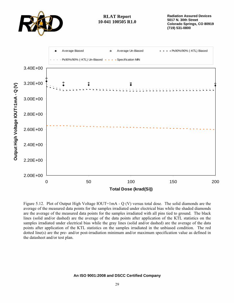
Figure 5.12. Plot of Output High Voltage IOUT=1mA - Q (V) versus total dose. The solid diamonds are theaverage of the measured data points for the samples irradiated under electrical bias while the shaded diamondsare the average of the measured data points for the samples irradiated with all pins tied to ground. The blacklines (solid and/or dashed) are the average of the data points after application of the KTL statistics on thesamples irradiated under electrical bias while the gray lines (solid and/or dashed) are the average of the datapoints after application of the KTL statistics on the samples irradiated in the unbiased condition. The reddotted line(s) are the pre- and/or post-irradiation minimum and/or maximum specification value as defined inthe datasheet and/or test plan.

RLAT Report 10-041 100505 R1.0
An ISO 9001:2008 and DSCC Certified Company
30
Radiation Assured Devices5017 N. 30th Street Colorado Springs, CO 80919 (719) 531-0800
Table 5.12. Raw data for Output High Voltage IOUT=1mA - Q (V) versus total dose,including the statistical analysis, specification and the status of the testing (pass/fail).
Output High Voltage IOUT=1mA - Q (V)
Device 0 20 50 100 200731 3.21E+00 3.16E+00 3.17E+00 3.16E+00 3.15E+00732 3.25E+00 3.20E+00 3.20E+00 3.20E+00 3.19E+00734 3.21E+00 3.16E+00 3.16E+00 3.16E+00 3.16E+00735 3.21E+00 3.16E+00 3.16E+00 3.16E+00 3.16E+00764 3.26E+00 3.21E+00 3.21E+00 3.23E+00 3.21E+00765 3.22E+00 3.16E+00 3.16E+00 3.16E+00 3.16E+00766 3.27E+00 3.21E+00 3.21E+00 3.22E+00 3.20E+00767 3.29E+00 3.25E+00 3.24E+00 3.23E+00 3.23E+00769 3.27E+00 3.20E+00 3.20E+00 3.20E+00 3.19E+00770 3.29E+00 3.24E+00 3.23E+00 3.23E+00 3.22E+00771 3.28E+00 3.22E+00 3.22E+00 3.22E+00 3.22E+00772 3.28E+00 3.23E+00 3.23E+00 3.22E+00 3.23E+00
Biased StatisticsAverage Biased 3.23E+00 3.18E+00 3.18E+00 3.18E+00 3.17E+00Std Dev Biased 2.54E-02 2.50E-02 2.22E-02 2.95E-02 2.34E-02Ps90%/90% (+KTL) Biased 3.30E+00 3.24E+00 3.24E+00 3.26E+00 3.24E+00Ps90%/90% (-KTL) Biased 3.16E+00 3.11E+00 3.12E+00 3.10E+00 3.11E+00Un-Biased StatisticsAverage Un-Biased 3.27E+00 3.21E+00 3.21E+00 3.20E+00 3.20E+00Std Dev Un-Biased 3.03E-02 3.28E-02 2.91E-02 2.88E-02 2.76E-02Ps90%/90% (+KTL) Un-Biased 3.35E+00 3.30E+00 3.29E+00 3.28E+00 3.27E+00Ps90%/90% (-KTL) Un-Biased 3.19E+00 3.12E+00 3.13E+00 3.13E+00 3.12E+00Specification MIN 2.65E+00 2.65E+00 2.64E+00 2.63E+00 2.60E+00Status PASS PASS PASS PASS PASS
Total Dose (krad(Si))

RLAT Report 10-041 100505 R1.0
An ISO 9001:2008 and DSCC Certified Company
31
Radiation Assured Devices5017 N. 30th Street Colorado Springs, CO 80919 (719) 531-0800
2.00E+00
2.20E+00
2.40E+00
2.60E+00
2.80E+00
3.00E+00
3.20E+00
0 50 100 150 200
Total Dose (krad(Si))
Out
put H
igh
Volta
ge IO
UT=
10m
A -
Q (V
)
Average Biased Average Un-Biased Ps90%/90% (-KTL) Biased
Ps90%/90% (-KTL) Un-Biased Specif ication MIN
Figure 5.13. Plot of Output High Voltage IOUT=10mA - Q (V) versus total dose. The solid diamonds are theaverage of the measured data points for the samples irradiated under electrical bias while the shaded diamondsare the average of the measured data points for the samples irradiated with all pins tied to ground. The blacklines (solid and/or dashed) are the average of the data points after application of the KTL statistics on thesamples irradiated under electrical bias while the gray lines (solid and/or dashed) are the average of the datapoints after application of the KTL statistics on the samples irradiated in the unbiased condition. The reddotted line(s) are the pre- and/or post-irradiation minimum and/or maximum specification value as defined inthe datasheet and/or test plan.

RLAT Report 10-041 100505 R1.0
An ISO 9001:2008 and DSCC Certified Company
32
Radiation Assured Devices5017 N. 30th Street Colorado Springs, CO 80919 (719) 531-0800
Table 5.13. Raw data for Output High Voltage IOUT=10mA - Q (V) versus total dose,including the statistical analysis, specification and the status of the testing (pass/fail).
Output High Voltage IOUT=10mA - Q (V)
Device 0 20 50 100 200731 3.03E+00 2.98E+00 2.99E+00 2.98E+00 2.98E+00732 3.07E+00 3.01E+00 3.02E+00 3.01E+00 3.01E+00734 3.03E+00 2.98E+00 2.98E+00 2.98E+00 2.98E+00735 3.03E+00 2.98E+00 2.98E+00 2.98E+00 2.98E+00764 3.08E+00 3.02E+00 3.03E+00 3.04E+00 3.02E+00765 3.04E+00 2.98E+00 2.99E+00 2.98E+00 2.98E+00766 3.08E+00 3.03E+00 3.03E+00 3.03E+00 3.02E+00767 3.10E+00 3.06E+00 3.05E+00 3.04E+00 3.04E+00769 3.09E+00 3.02E+00 3.02E+00 3.01E+00 3.01E+00770 3.10E+00 3.05E+00 3.05E+00 3.04E+00 3.04E+00771 3.09E+00 3.04E+00 3.03E+00 3.03E+00 3.04E+00772 3.10E+00 3.04E+00 3.04E+00 3.04E+00 3.04E+00
Biased StatisticsAverage Biased 3.05E+00 2.99E+00 3.00E+00 3.00E+00 2.99E+00Std Dev Biased 2.31E-02 2.24E-02 2.03E-02 2.65E-02 2.14E-02Ps90%/90% (+KTL) Biased 3.11E+00 3.06E+00 3.06E+00 3.07E+00 3.05E+00Ps90%/90% (-KTL) Biased 2.98E+00 2.93E+00 2.94E+00 2.93E+00 2.93E+00Un-Biased StatisticsAverage Un-Biased 3.08E+00 3.03E+00 3.03E+00 3.02E+00 3.02E+00Std Dev Un-Biased 2.70E-02 2.89E-02 2.58E-02 2.59E-02 2.50E-02Ps90%/90% (+KTL) Un-Biased 3.16E+00 3.11E+00 3.10E+00 3.09E+00 3.09E+00Ps90%/90% (-KTL) Un-Biased 3.01E+00 2.95E+00 2.95E+00 2.95E+00 2.95E+00Specification MIN 2.40E+00 2.40E+00 2.39E+00 2.38E+00 2.35E+00Status PASS PASS PASS PASS PASS
Total Dose (krad(Si))

RLAT Report 10-041 100505 R1.0
An ISO 9001:2008 and DSCC Certified Company
33
Radiation Assured Devices5017 N. 30th Street Colorado Springs, CO 80919 (719) 531-0800
0.00E+00
1.00E-01
2.00E-01
3.00E-01
4.00E-01
5.00E-01
6.00E-01
7.00E-01
0 50 100 150 200
Total Dose (krad(Si))
Out
put L
ow V
olta
ge IS
INK
=4m
A -
Q (V
)
Average Biased Average Un-Biased Ps90%/90% (+KTL) Biased
Ps90%/90% (+KTL) Un-Biased Specif ication MAX
Figure 5.14. Plot of Output Low Voltage ISINK=4mA - Q (V) versus total dose. The solid diamonds are theaverage of the measured data points for the samples irradiated under electrical bias while the shaded diamondsare the average of the measured data points for the samples irradiated with all pins tied to ground. The blacklines (solid and/or dashed) are the average of the data points after application of the KTL statistics on thesamples irradiated under electrical bias while the gray lines (solid and/or dashed) are the average of the datapoints after application of the KTL statistics on the samples irradiated in the unbiased condition. The reddotted line(s) are the pre- and/or post-irradiation minimum and/or maximum specification value as defined inthe datasheet and/or test plan.
RLAT Report 10-041 100505 R1.0
An ISO 9001:2008 and DSCC Certified Company
34
Radiation Assured Devices5017 N. 30th Street Colorado Springs, CO 80919 (719) 531-0800
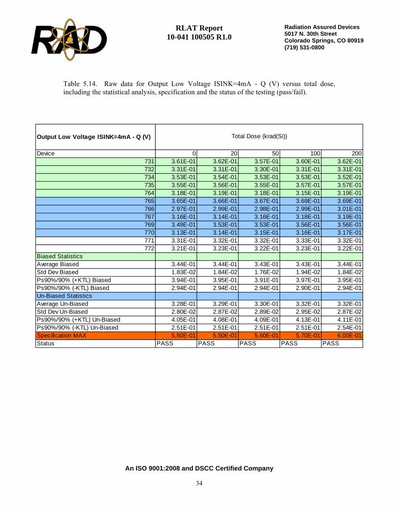
Table 5.14. Raw data for Output Low Voltage ISINK=4mA - Q (V) versus total dose,including the statistical analysis, specification and the status of the testing (pass/fail).
Output Low Voltage ISINK=4mA - Q (V)
Device 0 20 50 100 200731 3.61E-01 3.62E-01 3.57E-01 3.60E-01 3.62E-01732 3.31E-01 3.31E-01 3.30E-01 3.31E-01 3.31E-01734 3.53E-01 3.54E-01 3.53E-01 3.53E-01 3.52E-01735 3.55E-01 3.56E-01 3.55E-01 3.57E-01 3.57E-01764 3.18E-01 3.19E-01 3.18E-01 3.15E-01 3.19E-01765 3.65E-01 3.66E-01 3.67E-01 3.69E-01 3.69E-01766 2.97E-01 2.99E-01 2.98E-01 2.99E-01 3.01E-01767 3.16E-01 3.14E-01 3.16E-01 3.18E-01 3.19E-01769 3.49E-01 3.53E-01 3.53E-01 3.56E-01 3.56E-01770 3.13E-01 3.14E-01 3.15E-01 3.16E-01 3.17E-01771 3.31E-01 3.32E-01 3.32E-01 3.33E-01 3.32E-01772 3.21E-01 3.23E-01 3.22E-01 3.23E-01 3.22E-01
Biased StatisticsAverage Biased 3.44E-01 3.44E-01 3.43E-01 3.43E-01 3.44E-01Std Dev Biased 1.83E-02 1.84E-02 1.76E-02 1.94E-02 1.84E-02Ps90%/90% (+KTL) Biased 3.94E-01 3.95E-01 3.91E-01 3.97E-01 3.95E-01Ps90%/90% (-KTL) Biased 2.94E-01 2.94E-01 2.94E-01 2.90E-01 2.94E-01Un-Biased StatisticsAverage Un-Biased 3.28E-01 3.29E-01 3.30E-01 3.32E-01 3.32E-01Std Dev Un-Biased 2.80E-02 2.87E-02 2.89E-02 2.95E-02 2.87E-02Ps90%/90% (+KTL) Un-Biased 4.05E-01 4.08E-01 4.09E-01 4.13E-01 4.11E-01Ps90%/90% (-KTL) Un-Biased 2.51E-01 2.51E-01 2.51E-01 2.51E-01 2.54E-01Specification MAX 5.50E-01 5.50E-01 5.60E-01 5.70E-01 6.00E-01Status PASS PASS PASS PASS PASS
Total Dose (krad(Si))

RLAT Report 10-041 100505 R1.0
An ISO 9001:2008 and DSCC Certified Company
35
Radiation Assured Devices5017 N. 30th Street Colorado Springs, CO 80919 (719) 531-0800
2.00E+00
2.20E+00
2.40E+00
2.60E+00
2.80E+00
3.00E+00
3.20E+00
3.40E+00
0 50 100 150 200
Total Dose (krad(Si))
Out
put H
igh
Volta
ge IO
UT=
1mA
- Q
# (V
)
Average Biased Average Un-Biased Ps90%/90% (-KTL) Biased
Ps90%/90% (-KTL) Un-Biased Specif ication MIN
Figure 5.15. Plot of Output High Voltage IOUT=1mA - Q# (V) versus total dose. The solid diamonds are theaverage of the measured data points for the samples irradiated under electrical bias while the shaded diamondsare the average of the measured data points for the samples irradiated with all pins tied to ground. The blacklines (solid and/or dashed) are the average of the data points after application of the KTL statistics on thesamples irradiated under electrical bias while the gray lines (solid and/or dashed) are the average of the datapoints after application of the KTL statistics on the samples irradiated in the unbiased condition. The reddotted line(s) are the pre- and/or post-irradiation minimum and/or maximum specification value as defined inthe datasheet and/or test plan.
RLAT Report 10-041 100505 R1.0
An ISO 9001:2008 and DSCC Certified Company
36
Radiation Assured Devices5017 N. 30th Street Colorado Springs, CO 80919 (719) 531-0800
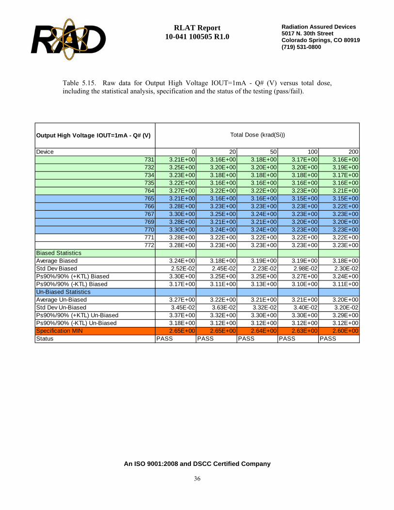
Table 5.15. Raw data for Output High Voltage IOUT=1mA - Q# (V) versus total dose,including the statistical analysis, specification and the status of the testing (pass/fail).
Output High Voltage IOUT=1mA - Q# (V)
Device 0 20 50 100 200731 3.21E+00 3.16E+00 3.18E+00 3.17E+00 3.16E+00732 3.25E+00 3.20E+00 3.20E+00 3.20E+00 3.19E+00734 3.23E+00 3.18E+00 3.18E+00 3.18E+00 3.17E+00735 3.22E+00 3.16E+00 3.16E+00 3.16E+00 3.16E+00764 3.27E+00 3.22E+00 3.22E+00 3.23E+00 3.21E+00765 3.21E+00 3.16E+00 3.16E+00 3.15E+00 3.15E+00766 3.28E+00 3.23E+00 3.23E+00 3.23E+00 3.22E+00767 3.30E+00 3.25E+00 3.24E+00 3.23E+00 3.23E+00769 3.28E+00 3.21E+00 3.21E+00 3.20E+00 3.20E+00770 3.30E+00 3.24E+00 3.24E+00 3.23E+00 3.23E+00771 3.28E+00 3.22E+00 3.22E+00 3.22E+00 3.22E+00772 3.28E+00 3.23E+00 3.23E+00 3.23E+00 3.23E+00
Biased StatisticsAverage Biased 3.24E+00 3.18E+00 3.19E+00 3.19E+00 3.18E+00Std Dev Biased 2.52E-02 2.45E-02 2.23E-02 2.98E-02 2.30E-02Ps90%/90% (+KTL) Biased 3.30E+00 3.25E+00 3.25E+00 3.27E+00 3.24E+00Ps90%/90% (-KTL) Biased 3.17E+00 3.11E+00 3.13E+00 3.10E+00 3.11E+00Un-Biased StatisticsAverage Un-Biased 3.27E+00 3.22E+00 3.21E+00 3.21E+00 3.20E+00Std Dev Un-Biased 3.45E-02 3.63E-02 3.32E-02 3.40E-02 3.20E-02Ps90%/90% (+KTL) Un-Biased 3.37E+00 3.32E+00 3.30E+00 3.30E+00 3.29E+00Ps90%/90% (-KTL) Un-Biased 3.18E+00 3.12E+00 3.12E+00 3.12E+00 3.12E+00Specification MIN 2.65E+00 2.65E+00 2.64E+00 2.63E+00 2.60E+00Status PASS PASS PASS PASS PASS
Total Dose (krad(Si))
RLAT Report 10-041 100505 R1.0
An ISO 9001:2008 and DSCC Certified Company
37
Radiation Assured Devices5017 N. 30th Street Colorado Springs, CO 80919 (719) 531-0800
2.00E+00
2.20E+00
2.40E+00
2.60E+00
2.80E+00
3.00E+00
3.20E+00
0 50 100 150 200
Total Dose (krad(Si))
Out
put H
igh
Volta
ge IO
UT=
10m
A -
Q#
(V)
Average Biased Average Un-Biased Ps90%/90% (-KTL) Biased
Ps90%/90% (-KTL) Un-Biased Specif ication MIN
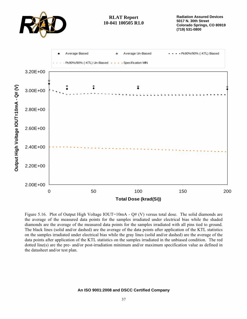
Figure 5.16. Plot of Output High Voltage IOUT=10mA - Q# (V) versus total dose. The solid diamonds arethe average of the measured data points for the samples irradiated under electrical bias while the shadeddiamonds are the average of the measured data points for the samples irradiated with all pins tied to ground.The black lines (solid and/or dashed) are the average of the data points after application of the KTL statisticson the samples irradiated under electrical bias while the gray lines (solid and/or dashed) are the average of thedata points after application of the KTL statistics on the samples irradiated in the unbiased condition. The reddotted line(s) are the pre- and/or post-irradiation minimum and/or maximum specification value as defined inthe datasheet and/or test plan.

RLAT Report 10-041 100505 R1.0
An ISO 9001:2008 and DSCC Certified Company
38
Radiation Assured Devices5017 N. 30th Street Colorado Springs, CO 80919 (719) 531-0800
Table 5.16. Raw data for Output High Voltage IOUT=10mA - Q# (V) versus total dose,including the statistical analysis, specification and the status of the testing (pass/fail).
Output High Voltage IOUT=10mA - Q# (V)
Device 0 20 50 100 200731 3.05E+00 3.00E+00 3.01E+00 3.00E+00 3.00E+00732 3.08E+00 3.03E+00 3.03E+00 3.03E+00 3.03E+00734 3.07E+00 3.01E+00 3.01E+00 3.01E+00 3.01E+00735 3.05E+00 3.00E+00 3.00E+00 3.00E+00 3.00E+00764 3.11E+00 3.05E+00 3.05E+00 3.07E+00 3.05E+00765 3.05E+00 3.00E+00 3.00E+00 2.99E+00 2.99E+00766 3.11E+00 3.06E+00 3.06E+00 3.06E+00 3.05E+00767 3.13E+00 3.08E+00 3.07E+00 3.06E+00 3.06E+00769 3.11E+00 3.04E+00 3.04E+00 3.04E+00 3.03E+00770 3.13E+00 3.07E+00 3.07E+00 3.06E+00 3.06E+00771 3.11E+00 3.05E+00 3.05E+00 3.05E+00 3.05E+00772 3.11E+00 3.06E+00 3.06E+00 3.06E+00 3.06E+00
Biased StatisticsAverage Biased 3.07E+00 3.02E+00 3.02E+00 3.02E+00 3.01E+00Std Dev Biased 2.26E-02 2.22E-02 2.00E-02 2.66E-02 2.13E-02Ps90%/90% (+KTL) Biased 3.13E+00 3.08E+00 3.08E+00 3.09E+00 3.07E+00Ps90%/90% (-KTL) Biased 3.01E+00 2.96E+00 2.97E+00 2.95E+00 2.96E+00Un-Biased StatisticsAverage Un-Biased 3.11E+00 3.05E+00 3.05E+00 3.04E+00 3.04E+00Std Dev Un-Biased 3.05E-02 3.25E-02 2.96E-02 3.01E-02 2.91E-02Ps90%/90% (+KTL) Un-Biased 3.19E+00 3.14E+00 3.13E+00 3.13E+00 3.12E+00Ps90%/90% (-KTL) Un-Biased 3.02E+00 2.96E+00 2.97E+00 2.96E+00 2.96E+00Specification MIN 2.40E+00 2.40E+00 2.39E+00 2.38E+00 2.35E+00Status PASS PASS PASS PASS PASS
Total Dose (krad(Si))

RLAT Report 10-041 100505 R1.0
An ISO 9001:2008 and DSCC Certified Company
39
Radiation Assured Devices5017 N. 30th Street Colorado Springs, CO 80919 (719) 531-0800
0.00E+00
1.00E-01
2.00E-01
3.00E-01
4.00E-01
5.00E-01
6.00E-01
7.00E-01
0 50 100 150 200
Total Dose (krad(Si))
Out
put L
ow V
olta
ge IS
INK
=4m
A -
Q#
(V)
Average Biased Average Un-Biased Ps90%/90% (+KTL) Biased
Ps90%/90% (+KTL) Un-Biased Specif ication MAX
Figure 5.17. Plot of Output Low Voltage ISINK=4mA - Q# (V) versus total dose. The solid diamonds are theaverage of the measured data points for the samples irradiated under electrical bias while the shaded diamondsare the average of the measured data points for the samples irradiated with all pins tied to ground. The blacklines (solid and/or dashed) are the average of the data points after application of the KTL statistics on thesamples irradiated under electrical bias while the gray lines (solid and/or dashed) are the average of the datapoints after application of the KTL statistics on the samples irradiated in the unbiased condition. The reddotted line(s) are the pre- and/or post-irradiation minimum and/or maximum specification value as defined inthe datasheet and/or test plan.

RLAT Report 10-041 100505 R1.0
An ISO 9001:2008 and DSCC Certified Company
40
Radiation Assured Devices5017 N. 30th Street Colorado Springs, CO 80919 (719) 531-0800
Table 5.17. Raw data for Output Low Voltage ISINK=4mA - Q# (V) versus total dose,including the statistical analysis, specification and the status of the testing (pass/fail).
Output Low Voltage ISINK=4mA - Q# (V)
Device 0 20 50 100 200731 3.64E-01 3.63E-01 3.58E-01 3.61E-01 3.61E-01732 3.42E-01 3.42E-01 3.40E-01 3.41E-01 3.41E-01734 3.60E-01 3.59E-01 3.58E-01 3.57E-01 3.56E-01735 3.47E-01 3.48E-01 3.46E-01 3.47E-01 3.46E-01764 3.20E-01 3.20E-01 3.19E-01 3.15E-01 3.19E-01765 3.47E-01 3.49E-01 3.49E-01 3.52E-01 3.52E-01766 3.32E-01 3.33E-01 3.33E-01 3.33E-01 3.34E-01767 3.15E-01 3.14E-01 3.15E-01 3.17E-01 3.17E-01769 3.48E-01 3.52E-01 3.52E-01 3.54E-01 3.55E-01770 3.15E-01 3.16E-01 3.17E-01 3.18E-01 3.19E-01771 3.19E-01 3.20E-01 3.20E-01 3.20E-01 3.20E-01772 3.18E-01 3.19E-01 3.19E-01 3.19E-01 3.19E-01
Biased StatisticsAverage Biased 3.47E-01 3.46E-01 3.44E-01 3.44E-01 3.45E-01Std Dev Biased 1.74E-02 1.70E-02 1.61E-02 1.81E-02 1.63E-02Ps90%/90% (+KTL) Biased 3.94E-01 3.93E-01 3.88E-01 3.94E-01 3.89E-01Ps90%/90% (-KTL) Biased 2.99E-01 3.00E-01 3.00E-01 2.94E-01 3.00E-01Un-Biased StatisticsAverage Un-Biased 3.31E-01 3.33E-01 3.33E-01 3.35E-01 3.35E-01Std Dev Un-Biased 1.63E-02 1.78E-02 1.73E-02 1.78E-02 1.78E-02Ps90%/90% (+KTL) Un-Biased 3.76E-01 3.82E-01 3.81E-01 3.84E-01 3.84E-01Ps90%/90% (-KTL) Un-Biased 2.87E-01 2.84E-01 2.86E-01 2.86E-01 2.87E-01Specification MAX 5.50E-01 5.50E-01 5.60E-01 5.70E-01 6.00E-01Status PASS PASS PASS PASS PASS
Total Dose (krad(Si))
RLAT Report 10-041 100505 R1.0
An ISO 9001:2008 and DSCC Certified Company
41
Radiation Assured Devices5017 N. 30th Street Colorado Springs, CO 80919 (719) 531-0800
0.00E+00
5.00E-01
1.00E+00
1.50E+00
2.00E+00
2.50E+00
0 50 100 150 200
Total Dose (krad(Si))
LATC
H P
in In
put V
olta
ge T
hres
hold
(V)
Average Biased Average Un-Biased Ps90%/90% (-KTL) Biased
Ps90%/90% (-KTL) Un-Biased Ps90%/90% (+KTL) Biased Ps90%/90% (+KTL) Un-Biased
Specif ication MIN Specif ication MAX
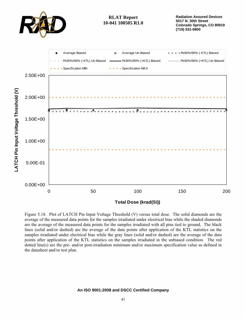
Figure 5.18. Plot of LATCH Pin Input Voltage Threshold (V) versus total dose. The solid diamonds are theaverage of the measured data points for the samples irradiated under electrical bias while the shaded diamondsare the average of the measured data points for the samples irradiated with all pins tied to ground. The blacklines (solid and/or dashed) are the average of the data points after application of the KTL statistics on thesamples irradiated under electrical bias while the gray lines (solid and/or dashed) are the average of the datapoints after application of the KTL statistics on the samples irradiated in the unbiased condition. The reddotted line(s) are the pre- and/or post-irradiation minimum and/or maximum specification value as defined inthe datasheet and/or test plan.
RLAT Report 10-041 100505 R1.0
An ISO 9001:2008 and DSCC Certified Company
42
Radiation Assured Devices5017 N. 30th Street Colorado Springs, CO 80919 (719) 531-0800
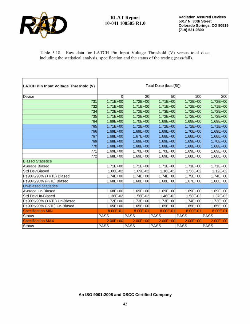
Table 5.18. Raw data for LATCH Pin Input Voltage Threshold (V) versus total dose,including the statistical analysis, specification and the status of the testing (pass/fail).
LATCH Pin Input Voltage Threshold (V)
Device 0 20 50 100 200731 1.71E+00 1.72E+00 1.71E+00 1.72E+00 1.72E+00732 1.71E+00 1.71E+00 1.71E+00 1.72E+00 1.71E+00734 1.72E+00 1.72E+00 1.73E+00 1.72E+00 1.72E+00735 1.71E+00 1.72E+00 1.72E+00 1.72E+00 1.72E+00764 1.69E+00 1.70E+00 1.69E+00 1.68E+00 1.69E+00765 1.71E+00 1.72E+00 1.72E+00 1.72E+00 1.71E+00766 1.69E+00 1.69E+00 1.69E+00 1.70E+00 1.69E+00767 1.68E+00 1.67E+00 1.68E+00 1.68E+00 1.68E+00769 1.68E+00 1.69E+00 1.69E+00 1.69E+00 1.70E+00770 1.68E+00 1.68E+00 1.68E+00 1.68E+00 1.68E+00771 1.69E+00 1.70E+00 1.70E+00 1.69E+00 1.69E+00772 1.68E+00 1.69E+00 1.69E+00 1.68E+00 1.68E+00
Biased StatisticsAverage Biased 1.71E+00 1.71E+00 1.71E+00 1.71E+00 1.71E+00Std Dev Biased 1.08E-02 1.09E-02 1.16E-02 1.56E-02 1.12E-02Ps90%/90% (+KTL) Biased 1.74E+00 1.74E+00 1.74E+00 1.75E+00 1.74E+00Ps90%/90% (-KTL) Biased 1.68E+00 1.68E+00 1.68E+00 1.67E+00 1.68E+00Un-Biased StatisticsAverage Un-Biased 1.68E+00 1.69E+00 1.69E+00 1.69E+00 1.69E+00Std Dev Un-Biased 1.36E-02 1.56E-02 1.46E-02 1.58E-02 1.37E-02Ps90%/90% (+KTL) Un-Biased 1.72E+00 1.73E+00 1.73E+00 1.74E+00 1.73E+00Ps90%/90% (-KTL) Un-Biased 1.65E+00 1.65E+00 1.65E+00 1.65E+00 1.65E+00Specification MIN 8.00E-01 8.00E-01 8.00E-01 8.00E-01 8.00E-01Status PASS PASS PASS PASS PASSSpecification MAX 2.00E+00 2.00E+00 2.00E+00 2.00E+00 2.00E+00Status PASS PASS PASS PASS PASS
Total Dose (krad(Si))
RLAT Report 10-041 100505 R1.0
An ISO 9001:2008 and DSCC Certified Company
43
Radiation Assured Devices5017 N. 30th Street Colorado Springs, CO 80919 (719) 531-0800
0.00E+00
1.00E-04
2.00E-04
3.00E-04
4.00E-04
5.00E-04
6.00E-04
7.00E-04
8.00E-04
9.00E-04
0 50 100 150 200
Total Dose (krad(Si))
LATC
H P
in C
urre
nt (A
)
Average Biased Average Un-Biased Ps90%/90% (+KTL) Biased
Ps90%/90% (+KTL) Un-Biased Specif ication MAX
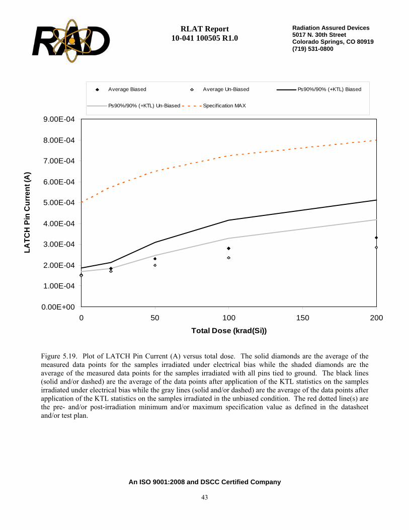
Figure 5.19. Plot of LATCH Pin Current (A) versus total dose. The solid diamonds are the average of themeasured data points for the samples irradiated under electrical bias while the shaded diamonds are theaverage of the measured data points for the samples irradiated with all pins tied to ground. The black lines(solid and/or dashed) are the average of the data points after application of the KTL statistics on the samplesirradiated under electrical bias while the gray lines (solid and/or dashed) are the average of the data points afterapplication of the KTL statistics on the samples irradiated in the unbiased condition. The red dotted line(s) arethe pre- and/or post-irradiation minimum and/or maximum specification value as defined in the datasheetand/or test plan.

RLAT Report 10-041 100505 R1.0
An ISO 9001:2008 and DSCC Certified Company
44
Radiation Assured Devices5017 N. 30th Street Colorado Springs, CO 80919 (719) 531-0800
Table 5.19. Raw data for LATCH Pin Current (A) versus total dose, including the statisticalanalysis, specification and the status of the testing (pass/fail).
LATCH Pin Current (A)
Device 0 20 50 100 200731 1.61E-04 1.78E-04 2.01E-04 2.07E-04 2.36E-04732 1.41E-04 1.77E-04 2.18E-04 2.80E-04 3.13E-04734 1.51E-04 1.92E-04 2.76E-04 3.37E-04 4.11E-04735 1.47E-04 1.75E-04 2.18E-04 2.73E-04 3.25E-04764 1.70E-04 1.99E-04 2.42E-04 3.09E-04 3.72E-04765 1.61E-04 1.67E-04 1.70E-04 1.74E-04 2.01E-04766 1.48E-04 1.68E-04 2.14E-04 2.61E-04 3.18E-04767 1.53E-04 1.74E-04 2.05E-04 2.55E-04 3.10E-04769 1.42E-04 1.77E-04 2.00E-04 2.39E-04 2.94E-04770 1.53E-04 1.69E-04 2.07E-04 2.45E-04 3.03E-04771 1.49E-04 1.58E-04 1.47E-04 1.44E-04 1.42E-04772 1.49E-04 1.42E-04 1.56E-04 1.63E-04 1.50E-04
Biased StatisticsAverage Biased 1.54E-04 1.84E-04 2.31E-04 2.81E-04 3.31E-04Std Dev Biased 1.15E-05 1.08E-05 2.90E-05 4.88E-05 6.61E-05Ps90%/90% (+KTL) Biased 1.85E-04 2.14E-04 3.10E-04 4.15E-04 5.13E-04Ps90%/90% (-KTL) Biased 1.22E-04 1.55E-04 1.51E-04 1.47E-04 1.50E-04Un-Biased StatisticsAverage Un-Biased 1.51E-04 1.71E-04 1.99E-04 2.35E-04 2.85E-04Std Dev Un-Biased 6.91E-06 4.41E-06 1.72E-05 3.50E-05 4.80E-05Ps90%/90% (+KTL) Un-Biased 1.70E-04 1.83E-04 2.46E-04 3.31E-04 4.17E-04Ps90%/90% (-KTL) Un-Biased 1.32E-04 1.59E-04 1.52E-04 1.39E-04 1.54E-04Specification MAX 5.00E-04 5.75E-04 6.50E-04 7.25E-04 8.00E-04Status PASS PASS PASS PASS PASS
Total Dose (krad(Si))

RLAT Report 10-041 100505 R1.0
An ISO 9001:2008 and DSCC Certified Company
45
Radiation Assured Devices5017 N. 30th Street Colorado Springs, CO 80919 (719) 531-0800
6.0. Summary / Conclusions
The total ionizing dose testing described in this final report was performed using the facilities at Radiation Assured Devices’ Longmire Laboratories in Colorado Springs, CO. The high dose rate total ionizing dose (TID) source is a JLSA 84-21 irradiator modified to provide a panoramic exposure. The Co-60 rods are held in the base of the irradiator heavily shielded by lead, during the radiation exposures the rod is raised by an electronic timer/controller and the exposure is performed in air. The dose rate for this irradiator in this configuration ranges from <1rad(Si)/s to a maximum of approximately 120rad(Si)/s, determined by the distance from the source.
The parametric data was obtained as read and record and all the raw data plus an attributes summary are contained in a separate Excel file. The attributes data contains the average, standard deviation and the average with the KTL values applied. The KTL value used in this work is 2.742 per MIL-HDBK-814 using one sided tolerance limits of 90/90 and a 5-piece sample size. The 90/90 KTL values were selected to match the statistical levels specified in the MIL-PRF-38535 sampling plan for the qualification of a radiation hardness assured (RHA) component. Note that the following criteria must be met for a device to pass the RLAT: following the radiation exposure each of the 5 pieces irradiated under electrical bias shall pass the specification value. The units irradiated without electrical bias and the KTL statistics are included in this report for reference only. If any of the 5 pieces irradiated under electrical bias exceed the datasheet specifications, then the lot could be logged as a failure.
Based on the criterion described above, the RH1016MW UltraFast Precision Comparator (from the lot date code/traceability information identified on the first page of this test report) PASSED the RLAT to the maximum dose level of 200krad(Si) with all measured parameters remaining within their respective datasheet specification values. Note that the data for the units-under-test irradiated in the unbiased condition and the KTL statistics presented in this report are for reference only and are not used for the determination of “PASS/FAIL” for the lot.
RLAT Report 10-041 100505 R1.0
An ISO 9001:2008 and DSCC Certified Company
46
Radiation Assured Devices5017 N. 30th Street Colorado Springs, CO 80919 (719) 531-0800
Appendix A: Photograph of device-under-test to show part markings
RLAT Report 10-041 100505 R1.0
An ISO 9001:2008 and DSCC Certified Company
47
Radiation Assured Devices5017 N. 30th Street Colorado Springs, CO 80919 (719) 531-0800
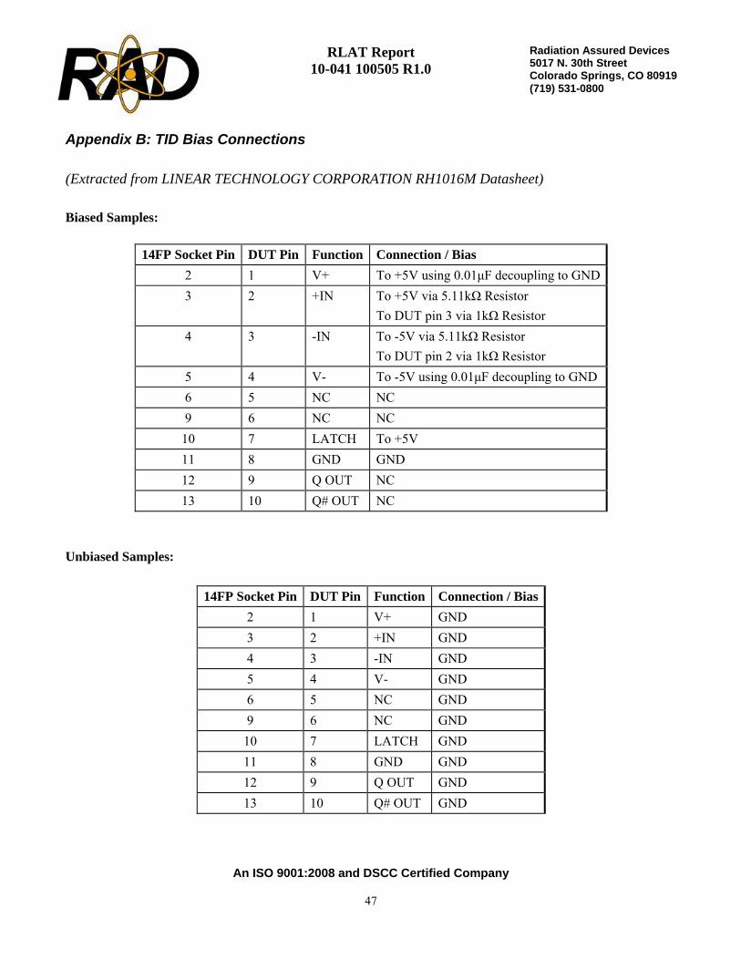
Appendix B: TID Bias Connections
(Extracted from LINEAR TECHNOLOGY CORPORATION RH1016M Datasheet)
Biased Samples:
Unbiased Samples:
14FP Socket Pin DUT Pin Function Connection / Bias 2 1 V+ To +5V using 0.01μF decoupling to GND3 2 +IN To +5V via 5.11kΩ Resistor
To DUT pin 3 via 1kΩ Resistor 4 3 -IN To -5V via 5.11kΩ Resistor
To DUT pin 2 via 1kΩ Resistor 5 4 V- To -5V using 0.01μF decoupling to GND 6 5 NC NC 9 6 NC NC
10 7 LATCH To +5V 11 8 GND GND 12 9 Q OUT NC 13 10 Q# OUT NC
14FP Socket Pin DUT Pin Function Connection / Bias 2 1 V+ GND 3 2 +IN GND 4 3 -IN GND 5 4 V- GND 6 5 NC GND 9 6 NC GND
10 7 LATCH GND 11 8 GND GND 12 9 Q OUT GND 13 10 Q# OUT GND
RLAT Report 10-041 100505 R1.0
An ISO 9001:2008 and DSCC Certified Company
48
Radiation Assured Devices5017 N. 30th Street Colorado Springs, CO 80919 (719) 531-0800
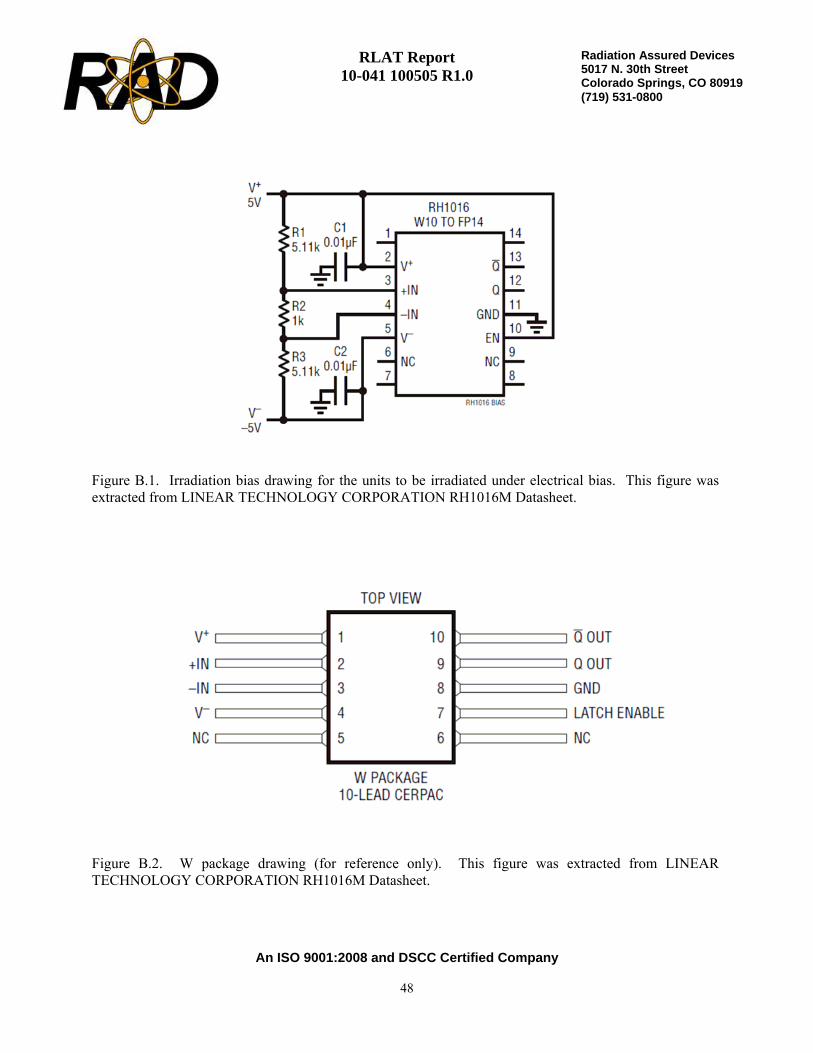
Figure B.1. Irradiation bias drawing for the units to be irradiated under electrical bias. This figure wasextracted from LINEAR TECHNOLOGY CORPORATION RH1016M Datasheet.
Figure B.2. W package drawing (for reference only). This figure was extracted from LINEARTECHNOLOGY CORPORATION RH1016M Datasheet.
RLAT Report 10-041 100505 R1.0
An ISO 9001:2008 and DSCC Certified Company
49
Radiation Assured Devices5017 N. 30th Street Colorado Springs, CO 80919 (719) 531-0800
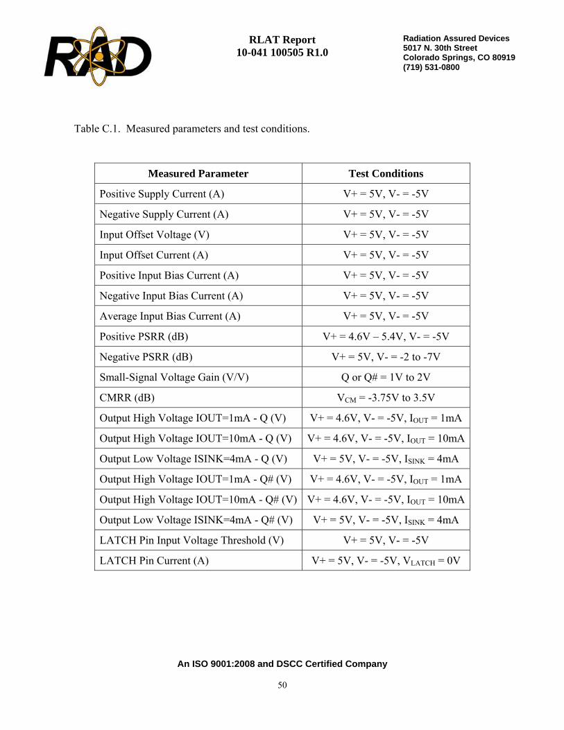
Appendix C: Electrical Test Parameters and Conditions All electrical tests for this device are performed on one of Radiation Assured Device’s LTS2020 Test Systems. The LTS2020 Test System is a programmable parametric tester that provides parameter measurements for a variety of digital, analog and mixed signal products including voltage regulators, voltage comparators, D to A and A to D converters. The LTS2020 Test System achieves accuracy and sensitivity through the use of software self-calibration and an internal relay matrix with separate family boards and custom personality adapter boards. The tester uses this relay matrix to connect the required test circuits, select the appropriate voltage / current sources and establish the needed measurement loops for all the tests performed. The tests will be conducted using the LTS-2101 Linear Family Board, LTS-0608 Socket Assembly and the RH1016 BGSS-100116 DUT board. The measured parameters and test conditions are shown in Tables C.1. A listing of the measurement precision/resolution for each parameter is shown in Tables C.2. The precision/resolution values were obtained either from test data or from the DAC resolution of the LTS-2020. To generate the precision/resolution shown in Table C.2, one of the units-under-test was tested repetitively (a total of 10-times with re-insertion between tests) to obtain the average test value and standard deviation. Using this test data MIL-HDBK-814 90/90 KTL statistics were applied to the measured standard deviation to generate the final measurement range. This value encompasses the precision/resolution of all aspects of the test system, including the LTS2020 mainframe, family board, socket assembly and DUT board as well as insertion error. In some cases, the measurement resolution is limited by the internal DACs, which results in a measured standard deviation of zero. In these instances the precision/resolution will be reported back as the LSB of the DAC. Note that the testing and statistics used in this document are based on an “analysis of variables” technique, which relies on small sample sizes to qualify much larger lot sizes (see MIL-HDBK-814, p. 91 for a discussion of statistical treatments). Not all measured parameters are well suited to this approach due to inherent large variations. One such parameter is pre-irradiation Small Signal Voltage Gain, where the device exhibits extreme sensitivity to input conditions, resulting in a very large standard deviation. If necessary, larger samples sizes could be used to qualify these parameters using an “attributes” approach.
RLAT Report 10-041 100505 R1.0
An ISO 9001:2008 and DSCC Certified Company
50
Radiation Assured Devices5017 N. 30th Street Colorado Springs, CO 80919 (719) 531-0800
Measured Parameter Test Conditions
Positive Supply Current (A) V+ = 5V, V- = -5V
Negative Supply Current (A) V+ = 5V, V- = -5V
Input Offset Voltage (V) V+ = 5V, V- = -5V
Input Offset Current (A) V+ = 5V, V- = -5V
Positive Input Bias Current (A) V+ = 5V, V- = -5V
Negative Input Bias Current (A) V+ = 5V, V- = -5V
Average Input Bias Current (A) V+ = 5V, V- = -5V
Positive PSRR (dB) V+ = 4.6V – 5.4V, V- = -5V
Negative PSRR (dB) V+ = 5V, V- = -2 to -7V
Small-Signal Voltage Gain (V/V) Q or Q# = 1V to 2V
CMRR (dB) VCM = -3.75V to 3.5V
Output High Voltage IOUT=1mA - Q (V) V+ = 4.6V, V- = -5V, IOUT = 1mA
Output High Voltage IOUT=10mA - Q (V) V+ = 4.6V, V- = -5V, IOUT = 10mA
Output Low Voltage ISINK=4mA - Q (V) V+ = 5V, V- = -5V, ISINK = 4mA
Output High Voltage IOUT=1mA - Q# (V) V+ = 4.6V, V- = -5V, IOUT = 1mA
Output High Voltage IOUT=10mA - Q# (V) V+ = 4.6V, V- = -5V, IOUT = 10mA
Output Low Voltage ISINK=4mA - Q# (V) V+ = 5V, V- = -5V, ISINK = 4mA
LATCH Pin Input Voltage Threshold (V) V+ = 5V, V- = -5V
LATCH Pin Current (A) V+ = 5V, V- = -5V, VLATCH = 0V
Table C.1. Measured parameters and test conditions.

RLAT Report 10-041 100505 R1.0
An ISO 9001:2008 and DSCC Certified Company
51
Radiation Assured Devices5017 N. 30th Street Colorado Springs, CO 80919 (719) 531-0800
Pre-Irradiation SpecificationMeasured Parameter
Min Max
Measurement Resolution/Precision
Positive Supply Current (A) 3.50E+01 ±1.42E-04
Negative Supply Current (A) -5.00E-03 ±7.63E-05
Input Offset Voltage (V) -3.00E-03 3.00E-03 ±2.10E-05
Input Offset Current (A) -1.00E-06 1.00E-06 ±4.07E-09
Positive Input Bias Current (A) -1.00E-05 1.00E-05 ±3.97E-08
Negative Input Bias Current (A) -1.00E-05 1.00E-05 ±3.91E-08
Average Input Bias Current (A) -1.00E-05 1.00E-05 ±3.95E-08
Positive PSRR (dB) 6.00E+01 ±1.72E+01
Negative PSRR (dB) 8.00E+01 ±1.85E+00
Small-Signal Voltage Gain (V/V) 1.40E+03 ±3.85E+01
CMRR (dB) 8.00E+01 ±1.00E-01
Output High Voltage IOUT=1mA - Q (V) 2.65E+00 ±3.06E-02
Output High Voltage IOUT=10mA - Q (V) 2.40E+00 ±2.62E-02
Output Low Voltage ISINK=4mA - Q (V) 5.50E-01 ±7.17E-03
Output High Voltage IOUT=1mA - Q# (V) 2.65E+00 ±2.95E-02
Output High Voltage IOUT=10mA - Q# (V) 2.40E+00 ±2.57E-02
Output Low Voltage ISINK=4mA - Q# (V) 5.50E-01 ±6.56E-03
LATCH Pin Input Voltage Threshold (V) 8.00E-01 2.00E+00 ±1.82E-02
LATCH Pin Current (A) 5.00E-04 ±1.51E-05
Table C.2. Measured parameters, pre-irradiation specifications, and measurementresolutions.
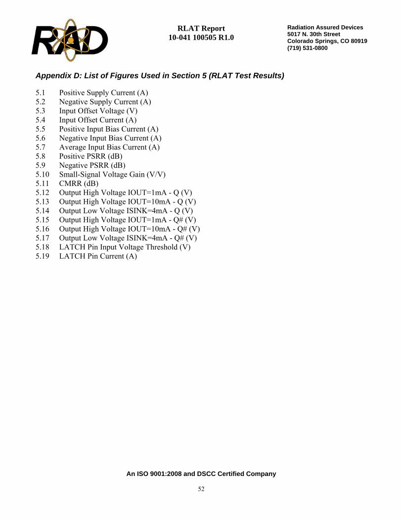
RLAT Report 10-041 100505 R1.0
An ISO 9001:2008 and DSCC Certified Company
52
Radiation Assured Devices5017 N. 30th Street Colorado Springs, CO 80919 (719) 531-0800
Appendix D: List of Figures Used in Section 5 (RLAT Test Results)
5.1 Positive Supply Current (A) 5.2 Negative Supply Current (A) 5.3 Input Offset Voltage (V) 5.4 Input Offset Current (A) 5.5 Positive Input Bias Current (A) 5.6 Negative Input Bias Current (A) 5.7 Average Input Bias Current (A) 5.8 Positive PSRR (dB) 5.9 Negative PSRR (dB) 5.10 Small-Signal Voltage Gain (V/V) 5.11 CMRR (dB) 5.12 Output High Voltage IOUT=1mA - Q (V) 5.13 Output High Voltage IOUT=10mA - Q (V) 5.14 Output Low Voltage ISINK=4mA - Q (V) 5.15 Output High Voltage IOUT=1mA - Q# (V) 5.16 Output High Voltage IOUT=10mA - Q# (V) 5.17 Output Low Voltage ISINK=4mA - Q# (V) 5.18 LATCH Pin Input Voltage Threshold (V) 5.19 LATCH Pin Current (A)