radiation physics - scott memorial...
TRANSCRIPT

1
RADIATION PHYSICS
Yan Yu, PhD, FAAPM, FASTRO
Professor and Vice Chair
Director of Medical Physics
Department of Radiation Oncology
Thomas Jefferson University
2017 Registry Review Course
Thomas Jefferson University
OVERVIEW
• Basic properties of radiation
• Sources of radiation
• Interaction with matter
• Measurement of radiation

2
OVERVIEW
• Basic properties of radiation
• Sources of radiation
• Interaction with matter
• Measurement of radiation
Electromagnetic Radiation
• Velocity = Frequency × Wavelength
• Velocity of EM radiation is “c” – speed of light

3
*Note: (1) Gamma rays refer to photons emitted from the nucleus.
(2) Gamma rays are not necessarily higher in energy than X-rays.
(3) Human eye can only detect a small range of the EM spectrum.
Atomic Structure
Nucleus:
<10-12 m
Atom:
<10-8 m
Electron:
tiny
The atom is mostly empty space

4
Energy levels of the hydrogen atom
Nuclear Structure

5
Subatomic particles
• Alpha particle (a): 2 protons and 2 neutrons bound together. – This is just a helium nucleus.
• Beta-minus particle (b-): electron emitted by the nucleus (rather than from an orbital shell). – How does the nucleus produce electrons?
• Beta-plus particle (b+): positron emitted by the nucleus.
• Gamma ray (g): photon emitted by the nucleus. – How does the nucleus produce photons?
Basic Physical Properties
• Radioactive decay
– Random process for each atom, but
predictable in an ensemble of many atoms
• Similar to (choose a or b):
– (a) photon interaction with matter
– (b) electron interaction with matter
• T1/2 Half life: time required for ½ of the
source material to decay.
• Decay mode: alpha, beta, e- capture
6
“electron volt – eV”
• This is an important unit of energy in
radiation physics.
• It is defined as energy acquired when an
electron falls through 1 volt.
– 1 electron has 1.6 x 10⁻¹⁹ C
– Energy through 1 volt = 1.6 x 10-19 C x 1 V
= 1.6 x 10⁻¹⁹ J
= 1 eV
Conservation Laws in Physics
1. Total energy is conserved
2. Total momentum is conserved
3. Total charge is conserved

7
Conservation Laws in Physics
1. Total energy is conserved Example:
• When an electron drifts through a high voltage
tube, potential energy (anode to cathode) is
converted to kinetic energy (velocity of the
electron).
• When one such fast electron strikes a target, its
kinetic energy is converted to
– X-ray energies
– heat
Conservation Laws in Physics
1. Total energy is conserved
2. Total momentum is conserved • Momentum = Mass x Velocity
• It is a vector
• Example:
• A positron (“anti-matter” of electron: just like an
electron, but with positive charge) at rest annihilates
with an electron. Two photons are created as a result.
These two photons are emitted in opposite directions so
that the total momentum is conserved (zero).
8
Einstein: E = m c2
• Equivalence of mass and energy – Expands the energy conservation law to mass and energy
– Example: Mass of an electron at rest is given as 9.1x10⁻³¹ kg. What is the energy needed to create an electron-positron pair?
• Question: Why not creating a single electron?
– ANS: Conservation of _____
• Energy = 2 x 9.1x10-31 x (3x108)2 J
= 2 x 8.2x10-14 J
= 2 x 511 keV = 1.02 MeV
• “Electron rest mass”: 511 keV
Summary of Fundamental
Quantities and Units
Fundamental Units (SI)
– Mass kg
– Length m
– Time s (sec)
– Current A

9
Summary of Fundamental
Quantities and Units
Derived Units
– Velocity m/s
– Acceleration m/s2 (or m s-2)
– Force N = kg m s-2
– Energy (work) J = N m
Summary of Fundamental
Quantities and Units
Electrical Units
– Charge C = A s
– Potential V = J/C

10
Summary of Fundamental
Quantities and Units This leads to units of interest to us…
– Absorbed dose gray (Gy) = J/kg
Sometimes 1 cGy is referred to as “1 rad”
– Exposure roentgen (R)
1 R = 2.58x10⁻⁴ C/kg
– Activity becquerel (Bq) = disintegration/sec
Also “curie” (Ci)
1 Ci = 3.7x10¹⁰ Bq
Exercise
• A patient has received 2 Gy of radiation
from you, and complains that he feels hot
in the irradiated area.
Do you think this is possible?

11
Exercise
Let’s turn this into a physics question…
• Given that 103 calories increases 1 kg of water by 1 °C, what is the rise in temperature due to absorption of 1 Gy of radiation? (1 calorie = 4.18 J)
• ANS:
Since 1 Gy = 1 J/kg = 1 / 4.18 calories/kg,
change in temperature =
1 / 4.18 calories/kg / (103 calories/kg °C)
= 2.4 x 10⁻⁴ °C
For 2 Gy of dose delivery, the rise in temperature is less than 5x10⁻⁴ °C.
You cannot sense such tiny temperature change!
OVERVIEW
• Basic properties of radiation
• Sources of radiation
• Interaction with matter
• Measurement of radiation

12
Production of X-rays
Wilhelm Conrad Röntgen
X-ray was discovered in 1895
Production of X-rays -- X-ray tube
Electrons Target
Cathode (-) Anode (+)
High voltage supply
Thermionic emission
Vacuum

13
Efficiency = 9 × 10 -10 Z V
Tungsten target
• Z=74 e.g. 100 kV efficiency = 0.7%
(heat…)
• melting point = 3370 °C
Production of X-rays: Bremsstrahlung
Brems-strahlung: “breaking radiation”
Anode design – line focus principle
A Electrons
a = A Sin θ
(6-17 degree)
θ
Anode
target
Focal spot: the apparent source of x-rays in the tube
Small enough to produce sharp image (0.1-2mm)
Large enough to tolerate a high heat loading
Electrons
target
X-ray X-ray
MV X-ray production:
Transmission target
Production of X-rays

14
X-ray / Gamma-ray
Producing Machines
• Linear accelerator (megavoltage machine)
• Cobalt-60 (“Teletherapy”) machine
• Kilovoltage machines
Linear accelerator (Linac)

15
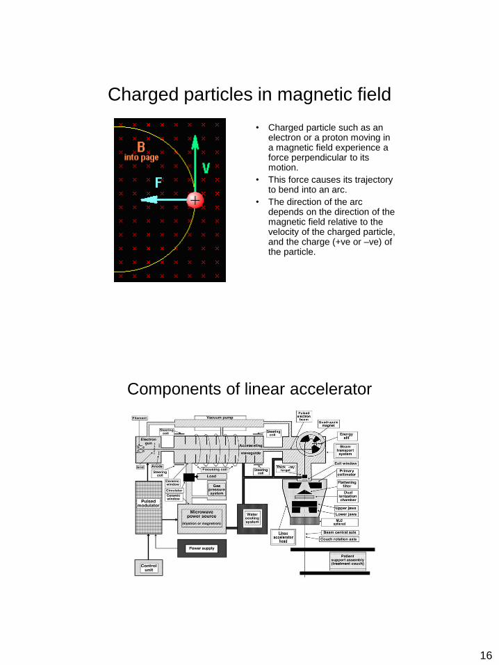
Components of linear accelerator
• Straight-through beam design: electron gun and target are permanently embedded into the accelerating waveguide, RF power generator is mounted in the gantry
Components of linear accelerator
Most common
16
Charged particles in magnetic field
• Charged particle such as an electron or a proton moving in a magnetic field experience a force perpendicular to its motion.
• This force causes its trajectory to bend into an arc.
• The direction of the arc depends on the direction of the magnetic field relative to the velocity of the charged particle, and the charge (+ve or –ve) of the particle.
Components of linear accelerator

17
Major components of a linear accelerator
• Electron gun: source of electron
• Klystron or magnetron: microwave power source, provides microwave power to accelerate electron
• Waveguide: conveys microwave power
• Accelerator tube (accelerating waveguide, or accelerator guide): microwave cavities energized by magnetron or klystron, in which electrons are accelerated
• Bending magnet: deflects electron from accelerator tube and focuses them on target
• Treatment head: contains beam shaping and monitoring devices

18
Magnetron
• Functions: microwave generator, generates microwave pulses of several microseconds duration.
• Repetition rate of several hundred pulses per second.
• Frequency ~3000 MHz.
• 2-5 MW peak power.
• Less costly but less stable than a klystron.
• Usually used to power lower energy linacs.
Klystron
• Function: microwave amplifier (needs low-power microwave input).
• 2 cavity structure: Buncher and Catcher.
• Electrons are accelerated into buncher, which is energized by low energy microwaves. Microwaves set up alternating E fields across cavity, leading to electron bunching.
• Bunches reach catcher cavity, induce charges across ends and generate retarding E field. Electrons decelerate, kinetic energy converted into high-power microwaves.
• Operates at 3-7 MW peak power
• Usually used in high energy Linacs

19
Accelerating waveguide
• General waveguide: “guides” electromagnetic waves from one point to another point
• Accelerating waveguide:
– Accelerate electron
– Series of adjacent, cylindrical evacuated microwave cavities
– Range from ~30 cm for 4-MeV units to > 1m for high-energy units
– First few cavities vary in size, accelerate and bunch electron in a similar way as klystron cavities
– Electrons gain energy, approach relativistic velocity
– Two types of accelerator structures: Standing-wave and Traveling-wave.
20
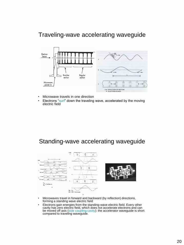
Traveling-wave accelerating waveguide
• Microwave travels in one direction
• Electrons “surf” down the traveling wave, accelerated by the moving electric field
Standing-wave accelerating waveguide
• Microwaves travel in forward and backward (by reflection) directions, forming a standing wave electric field
• Electrons gain energies from the standing-wave electric field. Every other cavity has zero electric field, which does not accelerate electrons and can be moved off axis (side coupling cavity): the accelerator waveguide is short compared to traveling waveguide.

21
Bending magnet • After leaving the accelerator
structure, electron beam continues through an evacuated bending magnet.
• Electrons are deflected by the bending magnet to either strike a target (x-ray beam) or exit through treatment head via thin window for electron therapy.
• 90º bending magnet (Chromatic magnet): beam is spread (spatial dispersion)
• 270°bending magnet (Achromatic magnet): beam is refocused
• Lower energy linacs have straight-through beam and do not need bending magnet.
Treatment head (photon therapy)
• Target: tungsten
• Flattening filter (lead,
steel, copper, brass, etc.)
• Beam collimation by
second collimators, which
consist of jaws and multi-
leaf collimator (MLC)

22
Flattening filter
Treatment head (electron therapy)
• X-ray target is removed
• Scattering foil (a fraction of millimeter, gold, silver, steel, aluminum, brass, etc) is used instead of the flattening filter used in photon therapy
• Beam collimation by jaws (i.e., secondary collimators) and electron applicator (cone)

23
Scattering foil
Monitor chamber
• Ionization chambers located in the treatment head to monitor dose, symmetry, energy
• Made of thin, low Z materials (aluminum or plastic), almost no effects on the beam
• Usually consists of two independent chambers: the second chamber is used as a backup to avoid overtreatment if the first one fails; In some machines, a
third chamber is used to monitor symmetry or energy

24
Cobolt-60 machine (“Teletherapy”)
• Co-60: high specific activity (Curies per gram), high average photon energy.
• Source, in form of solid cylinder, discs or pellets, contained in stainless steel capsule welded sealed, to ensure no leakage.
• Beta decay: 60Co decays with half-life of 5.26 years.
• 2 photons (gamma rays) are emitted: 1.17 and 1.33 MeV.
• The average energy is 1.25 MeV.
• Line spectrum, in contrast to the bremsstrahlung X-ray (continuous spectrum)

25
Cobalt-60 machine head
• Timer error:
Difference between
the beam-on time
setting and the time
the source is in the
treatment position
• Source continues
radiating, causing
significant level of
background radiation
Geometric Penumbra • Penumbra: region at the edge of a
radiation field where the dose rapidly falls as a function of distance from the beam axis
• Geometric penumbra: due to finite source size
• Geometric penumbra size
at depth of d:
P = S (SSD + d – SDD) / SDD,
on skin (i.e., d = 0):
P = S (SSD – SDD) / SDD,
where S is source size, SDD is source-diaphragm-distance, SSD is source-skin distance
• Penumbra trimmer (increasing SDD) is used in Cobal-60 machine to reduce the penumbra

26
Kilovoltage machines
• Contact therapy: 40-50 kV, for irradiation of shallow lesions 1-2mm, almost completely absorbed within 2 cm of tissue. A 0.5-1.0-mm-thick Al filter used to absorb very soft component of energy spectrum.
• Superficial therapy: 50-150 kV. For lesions of about 5 mm depth. Al filters of 1-6 mm used to harden beam.
• Orthovoltage therapy: 150-500 kV. Filters used to achieve HVLs between 1-4 mm Cu. Useful for lesions 2-3 cm deep.
• Supervoltage therapy: 500-1000 kV.
Cyclotron
• Consists of highly evacuated
metal half-discs (Dees)
• Accelerate heavy charged
particles (proton, deuterons)
by an oscillating electric field
between the Dees
• Magnetic field confines the
charged particles to a
circular path

27
Synchrotron
Cyclotron
Questions
• What is the purpose of a magnetron?
Klystron?

28
Questions
• What is achromatic bending magnet?
Questions
• Why is x-ray flattening filter of non-uniform
thickness while electron scattering foils are
of uniform thickness?

29
Questions
• What is the purpose of a monitor
chamber?
OVERVIEW
• Basic properties of radiation
• Sources of radiation
• Interaction with matter
• Measurement of radiation

30
Ionization vs. Excitation
• In ionization, an electron is
removed, resulting in an ion
pair: freed electron (-) and
the rest of the atom (+);
• Excitation transfers enough
energy to an orbital electron
to displace it further away
from the nucleus. Ionization Excitation
Ionizing Radiation
• Electromagnetic or particulate radiation capable of producing ion pairs by interaction with matter:
• X and Gamma rays (photons)
• Alpha particles
• Beta particles (electrons)
• Neutrons
• Charged nuclei
X,

31
Ionizing radiation interaction
by photons
• Photoelectric effect
• Compton effect
• Pair production
Relative importance of the three major types of photon
interactions. The curves show the values of Z and Eg
for which two types of effects are equal

32
Photoelectric interaction
(photo-ionization) • Incoming photon is completely absorbed by the atom
• Total photon energy is transferred to an orbital electron of the atom
• The electron is ejected from the atom (after overcoming its binding
energy)
– “the photoelectron”
• The atom is left with a shell vacancy
– Typically, inner shell vacancy
– Followed by orbital electron downward cascade to reach lower energy
state
• Characteristic radiation
• Auger emission
Photoelectric interaction
(cont.)

33
P.E. Effect: Points to remember
• P.E. involves bound electrons
• Probability is highly dependent on Z – Therefore a good discriminator of tissue composition in
diagnostic imaging
• Probability decreases rapidly with E – Important when photon energies are < ~ 100 keV
– Principle of dual energy imaging (inc. DEXA, dual-E CT/chest x-ray)
• Direction of photoelectron emission – At low energy, likely towards 90
– At high energy, forward directed
Compton Scattering
• “Inelastic scattering”
• Involves “free electrons”, or loosely bound outer shell orbital
electrons
• Photon transfers part of its energy to the electron, setting the latter
in motion (“Compton electron”)
– Compton electron moves in the forward (hemisphere) direction
– Scattered photon can be in any direction (incl. backscatter)
• Is the most dominant interaction in RT
– Between 100 keV to 10 MeV, it is the most probable process
• Cross section can be determined from Klein-Nishina formula

34
COMPTON EFFECT
Compton Scattering
Points to Remember • Cross section decreases at high energies
• Proportional to electron density
– Electron density per gram of any medium is approximately the same (except for hydrogen-rich – why?), so Compton energy transfer per gram is approximately constant in different types of tissues
• RT “Dose” is relatively uniform in tissues of different compositions
• Compton process is less efficient towards low photon energies
– Eventually will need P.E. to remove the photon from the beam

35
hn = e+ + e- + 1.02 MeV
Threshold: 1.022 MeV (equal to rest mass of 2 e)
Energy distribution between e+ and e- ranges from 0 – 50% each.
Momentum is conserved between all 4 species (inc. nucleus).
Pair Production
Attenuation Scatter Inverse Square

36
Attenuation
• Photon may be
– Absorbed- deposit all their energy
– Scattered- direction and energy changed
– Transmitted- unaffected
• If absorbed or scattered
– Removed from beam = Attenuated
– Attenuation is the removal of energy from the
beam
What can be an attenuator?
• Patient
• Table
• Block
• Tray
• Others?
37
Attenuation coefficient
• Represents the probability per unit
thickness (or per unit mass) that any one
photon will be attenuated
• Is a function of the material
• Is a function of the energy of the photon
beam
HVL
• Half value layer: is the thickness of
material required for a particular material
to cut the beam’s intensity in half.
• HVL is dependent on beam energy and
material

38
Transmission of Cs-137 beam (Mono-energy beam)
Transmission of
bremsstrahlung beam (Poly-energy beam)
“Beam Hardening”

39
Question
• An orthovoltage beam has an HVL of 2 mm Cu.
What percentage will be transmitted through 8 mm Cu?
a. 25%
b. 50%
c. 6.25%
d. 75%
e. 93.75%
1 HVL: 50%
2 HVL: 25%
3 HVL: 12.5%
4 HVL: _____
Question
• Add 1 mm Cu filtration to the beam. HVL
will increase or decrease? Why?
Beam hardenening…

40
Attenuation Scatter Inverse Square

41
Inverse Square Factor
I2
I1
D12
D22
Example Calculation
• The dose rate in air of a Co-60 teletherapy
machine is 80 cGy/min at 80 cm from the
source. What is the the dose rate in air at
100 cm?
Dose rate100cm (80 cm)2
____________ = _______
80 cGy/min (100 cm)2
Dose rate100cm = 0.64 × 80 cGy/min = 51.2 cGy/min

42
Photon vs. Electron Interaction
Indirect energy deposit Direct energy deposit
No interaction, or
One interaction
Continuous interactions
and loss of energy
Impossible to predict length of
travel of individual photon
Characterized by “Range”
Photon Electron
Electron Interaction Summary
• Soft and Hard Collision
– Collision with atomic electrons (ionization and excitation)
– Collisional Losses
• Bremsstrahlung
– Collision with nuclei
– Radiation Losses

43
Dominant Interactions
• Low Z media (i.e. Water or Tissue)
Collisional ionization
• High Z media (i.e. Lead)
– Bremsstrahlung
– Electron is very small. Two important effects observed for
electrons:
Large changes in energy and angle
Rapid deceleration bremsstrahlung
Problem 1
Electrons lose energy when passing through matter by
1. production of bremsstrahlung
2. photoelectric interactions
3. collision with other electrons
4. production of delta rays (“knock-out electrons”)
A. 1 & 2 only
B. 3 & 4 only
C. 1, 3, & 4 only
D. All are correct

44
Proton Beam Absorbers of pre-determined
thicknesses added
successively into beam to “pull
back” individual pristine Bragg
peaks
Pristine
Bragg peak
OVERVIEW
• Basic properties of radiation
• Sources of radiation
• Interaction with matter
• Measurement of radiation

45
Radiation Detectors
• Ionization chamber
• Geiger-Mueller (G-M) counter
• Proportional counter
Operational regions of
gas ionization detectors

46
Gas ionization detector example :
parallel plate ionization chamber
• Chamber with a fixed
volume of gas (e.g., air)
• Ionization of the gas
by photons or particles
• Electrodes with
polarization voltage
collect ions
Ion collection
• Ion recombination: e- + ion+ neutral atom (no net
charge, therefore measurement signal lost)
• Collection Efficiency
= charge collected / charge liberated by initial ionization

47
Ionization chamber: example --
thimble chamber
Ionization chamber: example --
thimble chamber
• Chamber wall has effective atomic number close to air
• Build-up cap is usually added for high energy photon beams to establish “electron equilibrium”
• Voltage: typically >= 300 volts

48
Farmer Chamber
Farmer Chamber

49
Proportional counter
• Operated in pulsed mode
• Detected count rate is proportional to the number of ion pairs formed in an
interaction
• Can measure low-intensity radiation and discriminate alpha and beta
particles - can be used in radiation safety work

50
• Operates in pulsed
mode- with very
high voltage
• Cascade effect
Geiger-Muller (G-M) counter
electron ion
Geiger-Muller counter
• Large charge amplification:
9–10 orders of magnitude
• Output current pulse
• Can detect single
ionization event
51
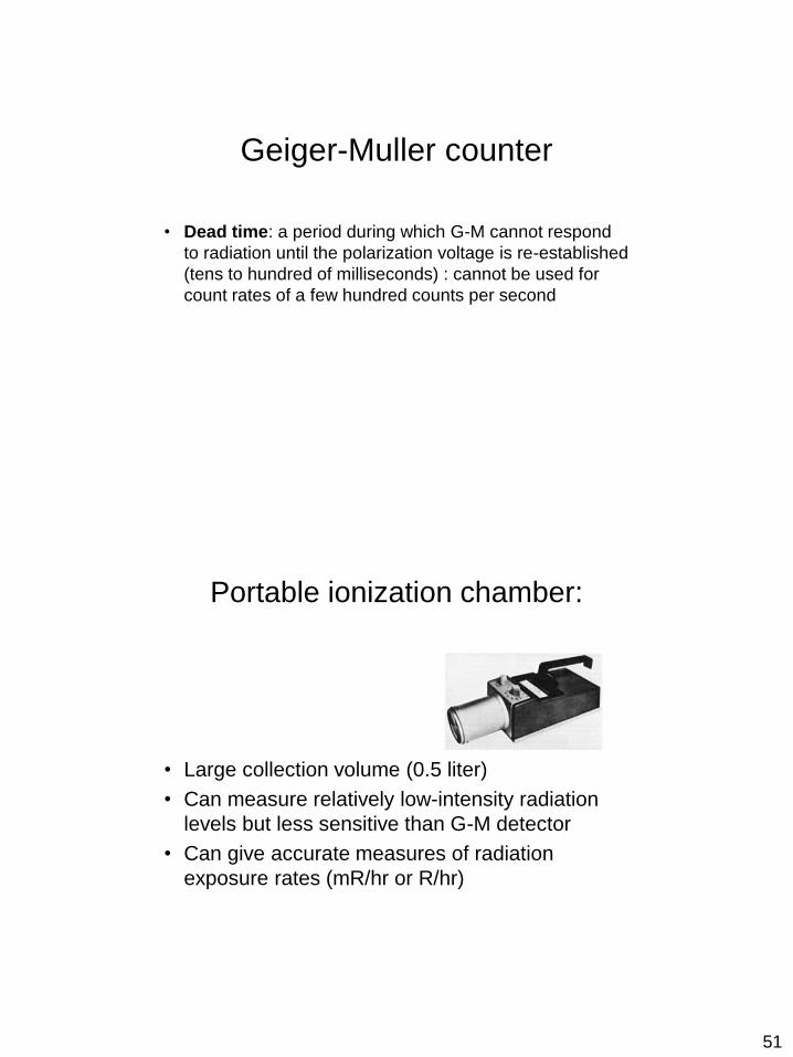
Geiger-Muller counter
• Dead time: a period during which G-M cannot respond
to radiation until the polarization voltage is re-established
(tens to hundred of milliseconds) : cannot be used for
count rates of a few hundred counts per second
Portable ionization chamber:
• Large collection volume (0.5 liter)
• Can measure relatively low-intensity radiation
levels but less sensitive than G-M detector
• Can give accurate measures of radiation
exposure rates (mR/hr or R/hr)
52
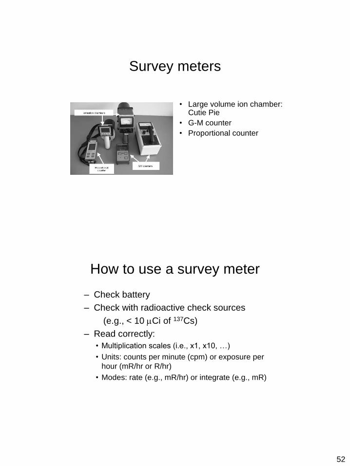
Survey meters
• Large volume ion chamber: Cutie Pie
• G-M counter
• Proportional counter
How to use a survey meter
– Check battery
– Check with radioactive check sources
(e.g., < 10 Ci of 137Cs)
– Read correctly:
• Multiplication scales (i.e., x1, x10, …)
• Units: counts per minute (cpm) or exposure per
hour (mR/hr or R/hr)
• Modes: rate (e.g., mR/hr) or integrate (e.g., mR)

53
Scintillation detector
• Scintillation crystal (NaI, CaF2) absorbs photon (x- or gamma-ray) -> ionization -> light emission
• The amount of light produced is proportional to the energy of the absorbed photon
• Used for measuring activity of nuclides, discriminating isotope, measuring brachytherapy source leakage (wipe test)
Neutron detector
• Moderated gas ionization detector: slow down neutron
by using low Z materials (e.g., hydrogen or boron) then
detect neutron presence
• Used in survey of linear accelerator (> 10 MV)

54
Thermoluminescent dosimeter
(TLD)
• Lithium fluoride (LiF) or CaF2:Mn, in the forms of rods or
chips
• Used in measuring patient skin dose or abutting field
dose, or used in personnel radiation protection
monitoring (badges)
Dosimeters – TLD
• Electrons are sitting in the valence band
• Ionizing radiation excites them to the conduction
band
• There are intrinsic impurities in the TLD
• Electrons can become trapped in these
impurities
• The TLD can then be heated which causes the
trapped electron to gain enough energy to jump
back to the valence band
• This causes a release of light photons that can
be detected by photomultiplier tube
ΔE
Valence Band
Conduction Band Ionizing radiation
Electron
Heat

55
• Intensity of light emitted is proportional to absorbed dose
TLD process
TLD reader

56
Dosimeters – TLD
• The amount of light released is proportional to the dose
• Advantages: – Small
– Large dose range
– Dose rate independent
• Disadvantages: – Not a permanent record
– Not real-time readout
– Labor intensive (annealing)
TLD badge

57
Dosimeters – OSL
• Optically stimulated luminescence
• Same principle as TLD but the trapped electrons are released using laser light as opposed to heat
• Doped aluminum oxide
• Simpler process
• No annealing
• Still need a calibration curve
Diode detector
• Unlike TLD, diode is capable of reading
and displaying dose immediately (real-time
measurement)
• Can be used in patient dosimetry to
measure patient surface dose
• Can be used in machine quality assurance
to measure beam flatness and symmetry

58
Diode detector used in patient
dosimetry
Separate diodes are designed for electron and photon
beams, and are designed for photons of different
energies (e.g., 6 MV, 18 MV).
Single diode, diode reader, and
diode array

59
Dosimeters – Arrays
• Patient Specific QA
• Have non-planar arrays for VMAT QA
MOSFET
MOSFET (metal oxide-silicon field effect transistor) - solid-state radiation detector
similar to diode:
-Irradiation causes charge accumulation, proportional to the energy deposited by
the beam;
-OneDose MOSFETs are pre-calibrated for Cobalt beam, correction factors can be
applied for the beam energy, modality, ssd, and field size;
-They are read right after the irradiation; the reading is saved in the memory chip;
- Caution advised for “surface” dose readings.

60

61
Film Dosimetry
Relationship between dose and film darkening (film’s optical density) is
established through calibration process:
- Dosimetry films are typically semi-linear with dose over specified range
of doses;
- Typically used films are: XTL films (1- 5 cGy), XV films (5 – 100 cGy)
and EDR films (50-400 cGy);
-Radiochromic films: do not need chemical processor;
- Films are not used for accurate dose measurements; they are usually
used for dose distribution mapping on a plane.

62
Question
• What kind of detector should you use to
determine the exposure rate around a 6
MV linear accelerator?
Ion chamber survey meter…

63
Question
• If you lost a 125I source in operating room
during a prostate implant, what instrument
would you use to locate its position?
G-M counter
Scintillation detector
Question
• Does an ionization chamber read too high
or too low if an insufficient ionization
potential is used?
+ve and –ve ions recombine: read too low

64
Question
• The reading of a Farmer chamber
measurement should be corrected
upwards when: 1. Temperature is higher than the standard value
2. Temperature is lower than the standard value
3. Pressure is higher than the standard value
4. Pressure is lower than the standard value
Standard values: T = 22 C (273 Kelvin); P = 760 mm Hg
Question
• Which region is the region of operation of G-M counter,
ionization chamber, and proportional counter?

65
Ionizing Radiation
Which picture represents x-ray interaction with medium?
alpha beta gamma
THANK YOU!