radio controlled quadcopter - · pdf fileradio controlled quadcopter ... programmable mixing:...
TRANSCRIPT

Vista UAV Quadcopter
Flight Battery
Spare Blades(2 black, 2 color) AAA Batteries (4)
Radio
Screwdriver
USB Charger
™
Radio ControlledQuadcopter
CHARGING
Plug the charger into a USB to AC adapter (DIDP1125 not included) or a computer USB port and connect the battery. The red LED will be steady while charging and fl ash when the charge is complete.
● NEVER leave the battery unattended while charging.● DO NOT allow the USB port to power down while the charger
is connected to the battery.● ALWAYS unplug the charger from the USB port and the
battery when charging is complete.● NEVER charge a puffed or damaged battery.
CONTROLLER SETUPRemove the screw and slide the cover down to insert the included 4 AAA batteries.
LINKING
1. Turn on the controller with the left stick at its lowest position.
2. Connect the battery to the Vista and place it on a level surface. The red LED on the quad will fl ash rapidly when the quad is linked to the controller.
1
2
FLYING
FLYING BASICS 1. Place the Vista on the ground at least 6 feet away with the
tail facing you. 2. Take off by “slowly” advancing the left stick until the quad
takes off. Change the altitude using small movements. 3. Use the right stick to make the Vista move left, right, forward
or backward. Keep in mind that when the nose is facing you, moving the right stick to the right will make the quad appear to move to the left.
4. Moving the left stick to the left or right will rotate the nose of the Vista left or right.
5. Always use small stick movements to control the Vista until you are familiar with the how the model responds to the controls.
6. Always unplug the Vista’s battery and turn off the transmitter when you’re done fl ying.
DUAL RATESThe agility of the Vista can be changed by pushing down on the right stick to select low or high control rates.
The overall rate sensitivity can be adjusted by:
1. Holding down the right stick until the controller beeps once.
2. Continue holding down the right stick and advance the left stick to the desired setting.
3. Release the right stick and return the left stick to its lowest position.The default setting is 50% (midstick) and low rates are 25% lower than high rates.
FLIGHT MODESThe Vista has advanced stabilization which automatically levels the quad when the right stick is centered and limits how far the Vista can tilt.
Press the Flight Mode button to toggle this off or on.
Easy Mode – Control rates are at a low setting. This is the default mode for the controller and should be used when indoors or if the pilot is just learning to fl y.
Normal Mode – The control rates are high. This mode should be selected when flying outdoors or when more agility is desired.
Advanced Mode – Advanced stabilization is off and the control rates are low. Your Vista will be more agile because there are no limits on how far it can turn in any direction.
Expert Mode – Advanced stabilization is off and the control rates are high.
FLIPSYour Vista can perform a flip when the flip button is pressed followed by moving the right stick in the desired fl ip direction. This stunt needs lots of room and should be done outside with relatively calm winds.
LOW BATTERY INDICATORSThe fl ight time is about 10 minutes. When the battery voltage gets low, the LEDs on the arms will fl ash slowly. The pilot should land as soon as possible to avoid damaging the battery. The battery should always be charged before the quadcopter is stored.
The controller will make a triple beep when the batteries need to be changed.
Easy Steady blue ONNormal Steady orange ON
Expert Flashing orange OFFAdvanced Flashing blue OFF
Mode LED Stab.LowHigh
HighLow
Sensitivity
SLT COMPATIBILITYThe Vista has a receiver that is compatible with other SLT transmitters like the Tactic™ TTX650. A transmitter with an ANYLINK can also be used provided it has helicopter programming, programmable mixing and at least 6 channels to control all the features of the Vista.
SETUP Model Type: Heli with H1 (one servo) swashplate type Servo Reversing: All Channels Normal (Tactic & Futaba) Servo Travel: 125%/125% Ail. & Ele. 100%/100% Thr., Rud., and all switches Throttle Curve: (0,25,50,75,100) Gyro (Ch 5): 25%/75%/125% - These are the sensitivity settings for the controls Pitch Curve (Ch 6): Set all points to 100% on low switch position - Advanced stabilization ON Set all points to 0% on high switch position - Advanced stabilization OFF Dual Rates: 50%/125% Aileron & Elevator Expo: -20/+100 Aileron & Elevator Programmable Mixing: CH 1 to CH 6, Left = 125%, Right = -125%, Use the dual rate switch (ON) as control CH 2 to CH 6, Left = 125%, Right = -125%, Use the dual rate switch (ON) as control
• Use a momentary switch for the Dual Rate, Expo and Programmable Mix settings.
• The high rate settings should be assigned to the ON position and are used for flipping.
QUADCOPTER SENSOR CALIBRATIONIf the quadcopter is constantly drifting in the same direction or any time a new fl ight control board has been installed, the sensors on the Vista should be calibrated.
1. Center all the trim adjustments. To center the trim settings, hold down one side of the trim button until you hear a long beep. If the controller stops beeping, release the trim button and hold down the other side.
2. Place your Vista on a level surface and link the quadcopter with the controller.
3. Put the controller in Normal Flight Mode (steady orange Flight Mode LED).
4. Press and hold the right stick in its lower right corner.
5. Move the left stick down and to the right. When the arm LEDs start to fl ash, release both sticks. The LEDs will stop fl ashing when the calibration is complete.
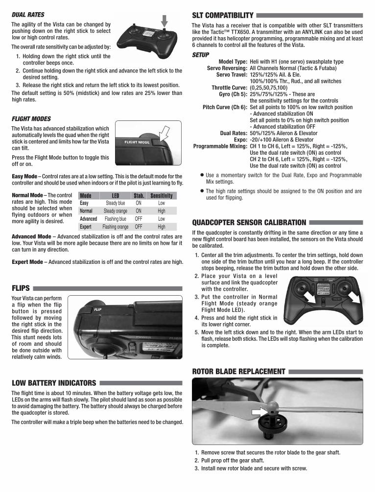
ROTOR BLADE REPLACEMENT
1. Remove screw that secures the rotor blade to the gear shaft. 2. Pull prop off the gear shaft. 3. Install new rotor blade and secure with screw.

REARBlack Blades,White LEDs
FRONTColor Blades,Color LEDs
A B
B A
NOTE: The rotor blades and each arm have arrows that indicate which way the prop rotates. Please check the arrows to verify that the correct replacement rotor blade has been installed.
GEAR SHAFT REPLACEMENT
1. Remove Rotor Blade from Gear Shaft 2. Push shaft down to remove it from the gear. 3. Install the new gear shaft and rotor blade if it is not damaged.
NOTE: While the gear is out, check it carefully for any cracks or damage to the teeth.
MOTOR REPLACEMENT
1. Remove screw securing the motor cover to the arm and pull the cover off the motor.
2. Use a small flat blade screwdriver to separate the motor plug from the socket. DO NOT pull the wires.
3. Remove the motor from the frame and insert the replacement. Make sure that the wire colors on the replacement motor are the same as the original. The motors for the clockwise props have black and white wires. The counter-clockwise props use motors with blue and red wires.
FLIGHT CONTROL BOARD REPLACEMENT 1. Remove all 4 motor covers and the two screws in the section between
the front and back arms.
2. Remove the battery frame.
3. Remove the LED covers and unplug all 4 motors. Carefully pull the motor wires out of the frame.
4. Remove the two canopy screws and the canopy. Under the canopy is canopy LED strip that must be unplugged from the control board.
5. Remove the 3 screws holding the control board and remove the board.
6. Install the canopy LED strip and the canopy. Be sure that the post is supporting the back of the LED strip.

7. Install the new control board and route the wires for motors. To prevent damage to the wires, route them between the guides on the inside of the arms.
8. Install the LED covers. Before tightening the screws, make sure the wires are positioned so they will not be damaged.
9. Replace the motor covers. 10. Calibrate the quadcopter sensors.
TROUBLESHOOTINGPROBLEM: The quadcopter will not respond to the transmitter.SOLUTION: (1) Turn off the transmitter and disconnect the battery for the
Vista. Re-link the quadcopter and the transmitter. (2) Charge or change the battery on the quadcopter.
PROBLEM: Red controller LED is slowly fl ashing after linking.SOLUTION: Replace AAA batteries.
PROBLEM: Unable to fl ip.SOLUTION: Battery voltage is too low.
PROBLEM: Quadcopter is shaking.SOLUTION: Check the props and the prop shafts for damage.
PROBLEM: The props spin but the quadcopter will not take off.SOLUTION: Rotor blades are incorrectly installed. See the Rotor Blade
Replacement section.
90-DAY LIMITED WARRANTY PLEASE DO NOT RETURN YOUR PRODUCT TO THE STORE. Dromida will repair or replace factory defects for 90 days from the date of purchase. This warranty specifi cally does not cover crash damage, misuse or abuse. To make a warranty claim, please contact our product support team at 1-217-398-8970 option 6 or e-mail us at [email protected]. If requested by Product Support, please send defective product to:
Hobby Services3002 N Apollo Dr., Suite #1Champaign, IL 61822
In the European Union, send it postpaid and insured to:
Service Abteilung Revell GmbH Tel: 01805-110111Henschelstrasse 20-30 (nur für Deutschland)32257 Bünde Germany
E-mail: [email protected]
Please include a note about the problem, your contact information, and a copy of the receipt.
This warranty applies only if the product is operated in compliance with the instructions and warnings provided with each model. Dromida assumes no liability except for the exclusive remedy or repair of parts as specifi ed above. Dromida shall not be liable for consequential or incidental damages. Some states do not allow the exclusion of consequential or incidental damages so the above exclusion may not apply to you. This warranty gives you specifi c legal rights and you may also have other rights which vary from state to state.
FCC REQUIREMENT This device complies with part 15 of the FCC rules. Operation is subject to the following two conditions.
(1) This device may not cause harmful interference.(2) This device must accept any interference received, including interference
that may cause undesired operation.
NOTE: THE MANUFACTURER IS NOT RESPONSIBLE FOR ANY RADIO OR TV INTERFERENCE CAUSED BY UNAUTHORIZED MODIFICATIONS TO THIS EQUIPMENT. SUCH MODIFICATIONS COULD VOID THE USER’S AUTHORITY TO OPERATE THE EQUIPMENT.
This equipment has been tested and found to comply with the limits for a Class B digital device, pursuant to Part 15 of the FCC Rules. These limits are designed to provide reasonable protection against harmful interference in a residential installation. This equipment generates, uses and can radiate radio frequency energy and, if not installed and used in accordance with the instructions, may cause harmful interference to radio communications. However, there is no guarantee that interference will not occur in a particular installation.
If this equipment does cause harmful interference to radio or television reception, which can be determined by turning the equipment off and on, the user is encouraged to try to correct the interference by one or more of the following measures:
● Reorient or relocate the receiving antenna.
● Increase the separation between the equipment and receiver.
● Connect the equipment into an outlet on a circuit different from that to which the receiver is connected.
● Consult the dealer or an experienced radio/TV technician for help.
CE COMPLIANCE INFORMATIONFOR THE EUROPEAN UNION INSTRUCTIONS FOR DISPOSAL OF WASTE EQUIPMENT BY PRIVATE USERS IN THE EUROPEAN UNION:
This symbol on the product or its packaging indicates this product must not be disposed of with other household waste. Instead, it is the user’s responsibility to dispose of their waste equipment by handing it over to a designated collection point for the recycling of waste electrical and electronic equipment. The separate collection and recycling of your waste equipment at the time of disposal will help to conserve natural resources and ensure that it is recycled in a manner that protects human health and the environment. For more information about where you can drop off your waste equipment for recycling, please contact your local city offi ce, your household waste disposal service or location where you purchased the product.
DECLARATION OF CONFORMITY:
Product: Dromida 2.4GHz 4-Channel Tx Rx FCC ID: IYFMR100Item number: DIDJ1105 MR100Equipment class: 1
MR100 transmitter: The objects of the declaration described here are in conformity with the requirements of the specifi cations listed below, following the provisions of the European 2006/95/EC Low Voltage Directive:
EN 60950-1:2006 Safety

The objects of the declaration described here are in conformity with the requirements of the specifi cations listed below, following the provisions of the European R&TTE directive 1995/5/EC:
EN300 328 V1.8.1.
Technical requirements for radio equipment
ETSI EN 301 489-1 V1.8.1, 301 489-17 V1.3.2 General EMC requirements for radio equipment
Hobbico, Inc.2904 Research RoadChampaign, IL USA 61826
Distributed in Europe by Revell GmbHD-32257 Bünde Germany
The associated regulatory agencies of the following countries recognize the noted certifi cations to this product as authorized for sale and use.
UK DE DK BG SE FI GREE LV LT PL CZ SK HURO SI AT IT ES PT IENL LU MT CY

dromida.com DIDE03xx v2© 2015 Dromida,® a Hobbico company.
REPLACEMENT PARTS
™
™ Radio ControlledQuadcopter
1 DIDE1170 Canopy Blue 1 DIDE1190 Canopy Green 1 DIDE1191 Canopy Red 1 DIDE1192 Canopy White 2 DIDE1171 Prop Set Blue 2 DIDE1172 Prop Set Green 2 DIDE1173 Prop Set Red 2 DIDE1174 Prop Set White 3 DIDE1175 Bearing Set 4 DIDE1176 Gear Set
5 DIDE1177 Prop Shaft 6 DIDE1178 Battery Frame 7 DIDE1179 Main Frame 8 DIDE1180 Motor Covers 9 DIDE1181 Main Mtr Cw L/F R/R 10 DIDE1182 Main Mtr Ccw R/F L/R 11 DIDE1183 Led Arm Covers Blue 11 DIDE1184 Led Arm Covers Green 11 DIDE1185 Led Arm Covers Red 11 DIDE1186 Led Arm Covers White
12 DIDE1187 E-Board Dampers 13 DIDE1188 Screw Set 14 DIDM1110 E-Board Blue 14 DIDM1111 E-Board Green 14 DIDM1112 E-Board Red 14 DIDM1113 E-Board White 15 DIDP1105 LiPo 1S 3.7 V 850 mAh 16 DIDE1189 Canopy LED Light Strip DIDJ1105 Transmitter
1
12
2
2
2
4
4
4
4
13
13
13
13
3
3
3
3
3
3
3
3
7
5
5
5
5
10
9
10
9
10
8
8
9
8
10
8
8
9
8
8
11
11
11
1113
13
13 8
13
13
13
12
14
14
6
15
13
13
16