radio set an/urc-9
TRANSCRIPT
("~
l"
NAVELEX 0967-LP-439-0010
TECHNICAL MANUAL
DESCRIPTION, OPERATION AND MAINTENANCE
RADIO SET '
AN/URC-9 ( )
Each transmital of this document outside of the Department of Defense must have approval of the issuing Service.
This Publication Supersedes: Navships 0967-305-4010, Dated 5 March 1969; Navships 0967-378-3010, ,Dated 13 March 1970; and Navelex 0967-125-6200, Dated August 1970.
Published by direction of Commander, Naval Electronic Systems Command
1 JANUARY 1973

NAVELEX 0967-439-0010
LIST OF EFFECTIVE PAGES
Total number of pages in this manual is 437 consisting of the following:
Page 11 Change Page 11 Change No. No. No.
Title 0 3-1 - 3-68 A 0 4-1 - 4-2 Flyleaf 0 5-1 - 5-206 i-xvi 0 6-1 - 6-92 1-1 - 1-14 0 7-1 - 7-6 2-1 - 2-18 0 Index-1 - Index-12
11 Zero in this column indicates an original page.
A
Errors found in this publication (other than obvious typographical errors), which have not been corrected by means of Temporary Corrections or Permanent Changes should be reported on the User Activity Comment Sheet located in the back of this technical manual. Such reports should include the complete title of the publication and the publication number (short title); identify the page and line or figure and location of the error; and be forwarded to Commander Naval Electronic Systems Command, Washington, D.C. 20360.
No.
0 0 0 0 0 0
'i~
·~

CHANGE RECORD
Change No. Date Title and/or Brief Description
("'
NAVELEX 0967-439-0010
Signature of Validating Officer
Flyleaf
(,
NAVELEX 0967-439-0010
TABLE OF CONTENTS
Chapter Page
1
2
LIST OF ILLUSTRATIONS.................................................. ix.
LIST OF TABLES ......•..•.•.••........••••••••.•••••••••.••.••.....•••••
GENERAL INFOR}{A TION • •.•••••••••••••••••.•••••••••••••••••••••••••••••••
1-1. 1-3.
1-9.
1-18. 1-20. 1-22. 1-24. 1-26. 1-28.
Scope . .................... . General 1-6. 1-7. 1-8.
Description ••••.•.••••• Radio Set AN/URC-9 •• Radio Set AN/URC-9A. Radio Sets AN/URC-9Y and AN/URC-9AY.
Description of Major Assemblies •••••••••••• 1-11. 1-13. 1-14. 1-15. 1-16. 1-17.
Receiver-Transmitter RT-581/URC-9 •••• Receiver-Transmitter RT-581A/URC-9 •••••• Power Supply PP-2702/URC-9 ••••• Power Supply PP-4706/URC-9Y ••••• Power Supply PP-4706A/URC-9Y~. Receiver-Transmitter Case CY-2959/URC-9 ••••
Reference Data .•.•.• Equipment Supplied •••.• Equipment Required But Not Supplied •••• Field Change Index •••••••••••• Transmission Range •••••.•••• Preparation For Reshipment •••
OPERA.TION • •••••••••••••••••••••••••••••••••••••••••••••••••••••••••••••
2-1.
2-11. 2-13.
Introduction •••••••••••• 2-4. 2-6.
2-10.
Remote Control •• Operation. Local S+N/N Squelch Control •••• Local Carrier Squelch Control.
Receive 2-7. 2-8. 2-9. Remote S+N/N and Carrier Squelch Control ••• Transmit Operation.
Controls and Indicators •• Operating Procedures ••••• 2-14. Modes of Operation ••
2-15. Normal Mode.
2-19.
2-16. 2-17. 2-18.
Retransmit Mode •• Tone Mode ••••••• Broadband Mode ••••
Frequency Selection •••••• 2-20. 2-21. 2-22.
Manual Frequency Selection •• Local Selection of Preset Channels •• Remote Selection of Preset Channels ••
xiii
1-1
1-1 1-1 1-1 1-1 1-1 1-1 1-1 1-2 1-2 1-2 1-2 1-2 1-2 1-8 1-8 1-8 1-11 1-11
2-1
2-1 2-3 2-3 2-3 2-3 2-3 2-3 2-3 2-7 2-7 2-7 2-7 2-8 2-8 2-8 2-8 2-8 2-8
;

NAVELEX 0967-439-0010
Chapter
2-29.
2-23. 2-24. 2-25.
Operator Procedures •••••••.•••.••••..••• . . . . . . . . . . . . . . . Operation Under Interfering Conditions •• Emergency Operation ................................... . 2-26. Remote Operation .............................. . 2-27. Local Operati:on ............................... .
2-28. Emergency Turn-Off .................................... . Operator Maintenance .......................................... . 2-30. 2-31.
2-34.
Operator Checks . .............................. . Operator Adjustments .................................. . 2-32. Presetting Channel Frequencies on AN/URC-9A •••• 2-33. Presetting Channel Frequencies on
AN/URC-9, 9Y, and 9AY . .........•..............• Emergency Maintenance ••••••••.•••.••••••••• 2-35. Procedure for Simple Repair •••.•••• 2-36. Fuse Location and Function ••••••••••.
3 FUNCTIONAL DESCRIPtiON ••••••
3-1.
3-12.
3-74.
ii
/""'
Overall 3-3. 3-4. 3-5. 3-6.
3-11.
Functional Description ................................ . Radio Set AN /URC-9 ••••.••.••••••••••••• Radio Set AN/URC-9Y and AN/URC-9AY ••.•••.•••••••••••••• Radio Set AN/URC-9A . ••.................•........•...... Modes of Operation .................................... . 3-7. Normal Mode . .................................. . 3-8. Retransmit Mode ............................... . 3-9 . Tone Mode . .................................... . 3-10. Broadband Mode ................................ . Channel Selection.
Transmit Function •••.••••. 3-13. 3-14. 3-18.
Receive 3-75. 3-77.
Signal Path ........................... . Detailed Description ••.•••.•.•••.•••••• Stage and Special Circuit Description ..•••••••.••. 3-19. Functional Relationship of Assemblies ••••• 3-20. Second IF Alnplifier . ..................... .
3-28. 3-35. 3-41. 3-51.
3-71.
3-21. 3-25.
Radio Set AN/URC-9A .•.••••••.••.•••.•• Radio Sets AN/URC-9, -9Y, and -9AY .•••
First IF Amplifier •••••.•••••••• Frequency Multiplier-Oscillator ..••. RF and PA Amplifier •.•••••.••..••••••••••.• Audio Amplifier and Modulator ••••••••.•••.•• 3-52. Normal Mode Transmit Audio Circuit •••• 3-56~ Compression Rectifier Circuit .••••••.. 3-59. 3-64. 3-66. 3-68.
Retransmit Mode Circuit .••••.••.•••.•• Duplex Transmission Circuit •••••.••••. Broadband Transmit Circuit ••.••••.•..• Tone Mode Circuit .•..•••••••.•••••••••
Directional Coupler ........................... . Function ............ . . . . . . . . . . . . . . . . . . . . . . . . . . . . . . . . . . . Signal Path •••••.•••• Detailed Description •
. . . . . . . . . . . . . . . . . . . . . . . . . . . . . . . . . . . . . . . . . . . . . . . . . . . . . . . . . . . .
Page
2-8 2-9 2-9 2-9 2-9 2-9 2-9 2-9 2-9 2-9
2-12 2-12 2-12 2-12
3-1
3-1 3-1 3-1 3-1 3-2 3-2 3-2 3-2 3-2 3-3 3-3 3-3 3-4 3-4 3-4 3-4 3-4 3-8 3-8 3-11 3-12 3-16 3-16 3-17 3-17 3-18 3-18 3-23 3-23 3-24 3-24 3-24
Chapter
c 3-152.
3-166.
l
NAVELEX 0967-439-0010
3-80.
Metering
Stage 3-81. 3-82. 3-83. 3-88. 3-96. 3-103.
3-118. 3-120.
3-134.
and Special Circuit D~scription ••.•..•.••.•...••• Relationship of Assemblies •.......•.••..•••.•.• Directional Coupler ........................... . RF and PA Amplifier ............. .............. . Frequency Multiplier-Oscillator (FMO) ••...••.•• First IF Amplifier ............................ . Second 3-104. 3-111. 500-kHz
IF Arn.plifier . .......................... . Radio Set AN/URC-9A .•......••....••••• Radio Set AN/URC-9, -9Y, and -9AY .•.•.
IF Filter ............................. . Third IF Amplifier ••.................•......... 3-122. Input Stages ......................... . 3-124. Audio Detector CR501. •••..•.••.....••• 3-126. Series Noise Limiter CR503 .•...•••••.. 3-128. IF AVC Circuit .•..•.........•.•.••...• 3-131. RF AVC Circuit ..•..••.•...••...•••.••• 3-133. Audio Amplifier V504 •.•.•••..•..•••.•• Audio Amplifier and Modulator •..•..•.•....•...• 3-135. Audio Amplifier and Driver Circuits ••• 3-139. Squelch Circuit •.••••.•.••.••..••••.•• 3-146. Signal-Plus-Noise to Noise Squelch
3-148. 3-149.
Discriminator Circuit ••.•.••.•..•••... Carrier Squelch Circuit .•.•.•..••••••• Broadband Receive Circuit .•.•.••.•••••
Circuits ............................................. . 3-153. General ............................................... . 3-154. Switch
3-155. 3-156. 3-157. 3-158. 3-159. 3-160. 3-161. 3-162. 3-163. 3-164. 3-165.
Positions ...................................... . S Meter .........•..•......•........•....•.•..•. St\TR • •••• • ••••• •:...• ••••••••••• • ••••••••••••• • •••• • • PWR • ••••••••••••••••••••••••••••••••••••••••••• DVR Ib . •...•............................•...... P A Ig •...•.•••.••••.•.•••.•••.•••••.•.•.•.••••. P A Ib . ........................................ . % Mod • ••••.•.••.....•.•..•.•••..•••••.•••.••••• Bias . .................................. · · · . · · · • +26. 5V ............... .......................... . + 125V . ........................................ . +325V ............ ............................. .
Power Distribution . ........................................... . 3-167. 3-172.
3-184.
AC Power Distribution- AN/URC-9 and -9A .•.•.•••.••.••• AC Power Distribution- AN/URC-9Y •.••••.••••••••••••••• 3-173. General···· ................................... . 3-175. Regulator Input Circuits •••.••••.••••••••••.••• 3-180. Frequency Controlled DC to AC Converter •••••••• AC Power Distribution- AN/URC-9AY •.••.••••••••.••.•••• 3-185. General· • • • · · · ................................ . 3-189. Primary Power Circuit ........................... . 3-190. 112-Volt 395-Hz Supply .•.•.•.•..••••••..••.•••• 3-191. 110-Volt 53-Hz and 26~5-Volt Supply .••••••.•••• 3-193. 36-Volt 1475-Hz Supply ••••.•••.••.•••••.•••••••
Page
3-25 3-25 3-26 3-26 3-27 3-28 3-29 3-29 3-31 3-32 3-32 3-32 3-33 3-33 3-34 3-34 3-37 3-37 3-37 3-38
3-41 3-41 3-41 3-42 3-42 3-42 3-42 3-42 3-42 3-42 3-44 3-44 3-44 3-44 3-44 3-44 3-44 3-45 3-45 3-45 3-46 3-46 3-46 3-48 3-48 3-50 3-50 3-50 3-50
;;;
NAVELEX 0967-439-0010
Chapter
3-232.
3-270.
3-195. DC Power Supply- AN/URC-9 and -9A ••••••••••.•••••.••.• 3-197. +26.5-Volt DC Supply •.•..••.•••••.••••.••••••.. 3-198. +325-Volt and +275-Volt DC Supply ••.••••••.••.. 3-199. +125-Volt and -11-Volt DC Supply ••••••••••.••.•
3-200. DC Power Supply - AN/URC-9Y ..•••••••••••••••.••.••.•..• 3-202. -11 Volts DC .................................. . 3-203. +26 Volts DC .................................. . 3-204. +125 Volts DC ••.•..•••••.•••••••••••••••••.•.•• 3-205. +325 Volts DC and +275 Volts DC ••••••••••..••••
3-206. DC Power Supply- AN/URC-9AY •....•.•...•••••••.••.•••.• 3-208. +26. 5 Volts DC ................................ . 3-209. +325 Volts DC and +275 Volts DC ••••••••••••••.. 3-210. +125 Volts DC and -11 Volts DC ••••••••••••.••.. 3-211. -6.3 Volts DC ................................. .
3-212. DC Power Distribution- Receive ••••.•••••.••••••••.•••• 3-213. +275-Volt DC Distribution •••••••••••••••.•••.•• 3-216. +125-Volt DC Distribution ••••••••••••.••.•••.•• 3-218. -11-Volt DC Distribution ••••.•••.•••••••••.•••• 3-219. +26.5-Volt DC Distribution •••••••••••••.••.••••
3-220. DC Power Distribution-Transmit •••.••••••••.•.•••••.••.• 3-221. +325-Volt DC Distribution ••.•..•••.••.••••••.•• 3-225. +125~Volt DC Distribution ••.••.••••••••••.••••• 3-228. -11-Volt DC Distribution •••.•..•••.••••••••••.• 3-230. +26.5-Volt DC Distribution ••••••••.•••••••••..•
Frequency Selection . .......................................... . 3-233. Frequency Conversion .................................. . 3-240. Electromechanical Tuning Elements •••...•••.••.••.•••.•. 3-247. Frequency Selector .................................... .
3-248. 3-250. 3-253. 3-254. 3-267.
General . ...................................... . Local Preset Channel Selection ••••••••••••••••• Remote Preset Channel Selection •••••••••••••••• Automatic Frequency Selection .••••••••••••••..• Manual Frequency Selection ••••••••••••••••••.••
Keying In The Normal Mode . .................................... .
4 SCHEDULED MAINTENAN'CE • ••••••••••••••••••••.•••••••••••••••••••••••.••••
4-1. 4-3. 4-5.
Introduction . ................................................. . Maintenance Schedule .......................................... . In-Port Procedures . ........................................... .
5 TROUBLESHOOTING AND CORRECTIVE MAINTENANCE ••••.•••••.•••••••••••••••.••
iv
5-1. 5-4.
Organizational Maintenance Responsibility •••••••••••••••••••••• General Inf orrna t ion . .......................................... . 5-5. Maintenance and Material Management(3-M) System •••••••• 5-6. Reference Standards ........................... , ....... . 5-7. List of Tables . ....................................... . 5-8. Reference Data •••••••••••.••••••••••••••••••••••••••••• 5-9. UHF Maintenance . ....................................... . 5-10. Alignment and Adjustment Procedure •••••••••••••••••.•••
Page .~
3-51 3-51 3-51 3-51 3-52 3-52 3-52 3-52 3-52 3-52 3-53 3-53 3-53 3-53 3-53 3-53 3-54 3-54 3-54 3-55 3-55 3-55 3-56 3-56 3-56 3-57 3-58 3-63 3-63 3-63 3-64 3-64 3-67 3-67
4-1
4-1 4-1 4-1
5-1
5-l 5-l 5-l 5-2 5-2 5-2 5-2 5-2

Chapter
5-25.
5-28.
5-11. 5-12. 5-13. 5-16. 5-18. 5-19. 5-20.
5-23.
NAVELEX 0967-439-0010
Test Equipment ........................................ . Test Points ........................................... . RF Tuners . ..•...•..•.•...••.......••..••...........•... Safety ................................................ . Radio Set Reference Designations •••.•••••••.••..•••..•• Troubleshooting Philosophy •.•.••••••.•.•.•••••...•.•••• Special Cables . ....................................... . 5-21. Maintenance . .................................. . 5-22. Intra-assembly ................................ . Overall Checkout and Troubleshooting Procedure
Page
5-3 5-9 5-9 5-9 5-9 5-10 5-10 5-10 5-11
for Radio Set AN/URC-9( ) .•••..••.••..••••..•.•....•••• 5-24. Preliminary Control Settings .•.••.••.•.•..•....••..•••.
5-11 5-11 5-22 5-22 5-22 5-22
Initial Setup for Alignment and Adjustment of RT-581 ••...•••••• 5-26. Equipment Setup ....................................... . 5-27. Radio Set AN/URC-9 Control Settings •.••.••••••.•..••••• RT-581 Alignment, Adjustment and Troubleshooting Procedures ..•• 5-30. Power Supply Checks, Adjustments
5-35.
5-41.
5-49.
and Troubleshooting .................................... 5-23 5-31. Power Supply PP-4706/URC-9Y
Electrical Check ............................... 5-23 5-32. Power Supply PP-4706/URC-9Y
Electrical Adjustment . .- •••••••••.•.••.•••.•••• • 5-23 5-33. Power Supply PP-4706/URC-9Y Troubleshooting
(AN /URC-9Y only) • . • . • • . • • . • • • • . . • • • • • • • • . • • • • • • 5-23 5-34. Power Supply PP-4706A/URC-9Y Troubleshooting
(AN/URC-9AY only).............................. 5-23 Second IF Amplifier Alignment, Adjustment and Troubleshooting ................................... . 5-36. 5-37. 5-38. 5-39. 5-40.
Second IF Amplifier Mechanical Check ••••••••••• Second IF Amplifier Mechanical Alignment ••••••• Second IF Amplifier Electrical Check •..•.•••.•• Second IF Amplifier Electrical Alignment .•.•••• Second IF Amplifier Troubleshooting (Transmit) .................................... .
First IF Amplifier Alignment, Adjustment, and Troubleshooting ..............•..................... 5-42. 5-43. 5-44. 5-45. 5-46. 5-47. 5-48.
First IF Amplifier Mechanical Check •••.•••••••. First IF Amplifier Mechanical Alignment ••••.•.• First IF Amplifier Electrical Check •••••..••••. First IF Amplifier Electrical Alignment •••••••• S Meter Zero Check .••.•...•.•....•.•.. 'll ••••••••
S Meter Zero Electrical Alignment •••.•••••••••• First IF Amplifier Troubleshooting ( Transmit) .................................... .
Frequency Multiplier-Oscillator (FMO) Alignment,
5-23 5-23 5-25 5-25 5-27
5-28
5-29 5-29 5-29 5-29 5-30 5-32 5-32
5-33
Adjustment and Troubleshooting •••••••••••••••••••• ••••• 5-34 5-50. FMO Mechanical Check ••••••••••••••••••••••••••• 5-34 5-51. FMO Mechanical Alignment ••.•.•••••••••••••••••• 5-35 5-52. FMO Electrical Check •••••••••••••••••••• ~······ 5-35 5-53. FMO Electrical Alignment ••••.•••••••••••••••••• 5-37
v

NAVELEX 0967-439-0010
Chapter
5-56.
5-63.
5-68.
5-71.
S:-74.
5-77.
5-81.
5-82.
5-85.
v·i
5-54. 5-55. RF and 5-57. 5-58. 5-59. 5-60. 5-61. 5-62. Audio
FMO Troubleshooting (Transmit) ..••.•..•.••.•••• FMO Intermittent Operation •.•....•.•.••.•..•••.
PA Alignment, Adjustment and Troubleshooting •..• RF and PA Mechanical Check ..••.•.•.•••••. , .•••• RF and PA Mechanical Alignment .......•.•....... RF and PA Electrical Check ..•••..........••...• RF and PA Electrical Alignment .••.••..••..•..•. RF and PA Troubleshooting (Transmit) ..•••.••... RF and PA Intermittent Operation •...•..••.••...
Amplifier and Modulator Checks, Adjustments, and Troubleshooting ..•..••••....•...•••••• 5-64. Hodulator Audio Level Check .....•••...••••.•... 5-65. Modulator Audio Level Adjustment •••..•..••••••. 5-66. Retransmit Audio Level Check and Adjustment •... 5-67. Audio Amplifier and Modulator
Troubleshooting (Transmit) .••...••••.•..•..•.•. Frequency Selector Alignment and Adjustment ••••...••.•. 5-69. Frequency Selector Mechanical Check •.••••.••... 5-70. Frequency Selector Mechanical Adjustment .•••••. Third IF Amplifier and Audio Amplifier and Modulator Check and Troubleshooting (Receive) ...•.•••....•..•.•.. 5-72. Third IF Amplifier and Audio Amplifier
and Modulator Check (Receive) •..••••.•.••••.••• 5-73. Third IF Amplifier and Audio Amplifier
and Modulator Troubleshooting (Receive) •.•....• Second IF Amplifier Check and Troubleshooting
Page
5-40 5-40 5-43 5-43 5-44 5-44 5-45 5-48 5-48
5-52 5-52 5-53 5-53
5-54 5-55 5-55 5-56
5-57
5-57
5-58
(Receive).............................................. 5-59 5-75. Second IF Amplifier Electrical
Check (Receive)................................ 5-59 5-76. Second IF Amplifier Troubleshooting
(Receive)...................................... 5-60 First IF Amplifier Alignment, Adjustment and Troubleshooting (Receive).......................... 5-61 5-78. First IF Amplifier Electrical
Check (Receive)................ . . . . . • . . . . . . • • • . 5-61 5-79. First IF Amplifier Electrical
Alignment (Receive) •.•.•.......•..•.....•.•...• 5-62 5-80. First IF Amplifier Troubleshooting
(Receive)...................................... 5-62 Frequency Mtuliplier-Oscillator (FMO) Alignment and Adjustment (Receive) .•..•..•..•..••.•..••••••..••.• RF and PA Check and Troubleshooting (Receive) •.•.•..••. 5-83. RF and PA Electrical Check (Receive) •••...•.•.. 5-84. RF and PA Troubleshooting (Receive) .••..•...•.• Squelch Level Check, Alignment and Troubleshooting (Receive) .•.•••...•...•••••...••••.••.• 5-86. Carrier Squelch Level Check (Receive) ..•.•••... 5-87. Carrier Squelch Level Electrical
Alignment (Receive) ........................... .
5-63 5-63 5-63 5-64
5-64 5-64
5-65 ,J

'" ~·~
l
Chapter
5-94.
5-91.
Repair 5-96.
5-99.
5-102.
5-108.
5-113.
5-119.
5-124.
5-127.
5-130.
5-133.
NAVELEX 0967-439-0010
5-88. Signal-Plus-Noise Tp Noise (S+N/N) Squelch Check (Receive) •••.••••.•••.•••..••••••
5-89. Signal-Plus-Noise To Noise (S+N/N) Squelch Electrical Alignment (Receive) ••••••••••..•••••
5-90. Squelch Level Troubleshooting (Receive) ••.••••. R/T Centrifugal Fan Strobe Check and Troubleshooting ••• 5-92. R/T Centrifugal Fan Strobe Check ••.•••.•.•••••• 5-93. R/T Centrifugal Fan Troubleshooting ••.•••••••••
Procedures for Radio Set AN/URC-9 ••.••••••••.••••••••••• Power Supplies PP-2702, PP-4706 and PP-4706A ••••••••••• 5-97. Removal ....................................... . 5-98. Replacement . .................................. . Receiver-Transmitter RT-581( )/URC-9 •••.••••.••••.•.••• 5-100. Removal . ...................................... . 5-101. Replacement . .................................. . Second 5-103. 5-104. 5-105. 5-106. 5-107.
IF .Amplifier ................................... . Removal . ...................................... . Crystal Replacement ........................... . Selector Switch Replacement (S401 and S402) •••• Lubrication . .................................. . Replacement . .................................. .
First IF knplifier .................................... . 5-109. Removal . ...................................... . 5-110. Tuning Core Replacement (0301 through 0307) •••• 5-111. Crystal Replacement (Y301 through Y310) •••••••• 5-112. Replacement ................................... . Frequency Multiplier-Oscillator (FMO) ••••••••••.••••••• 5-114. Removal . ...................................... . 5-115. General Maintenance . ....... · ................... . 5-116. Crystal Replacement •••.•••••••••••••••••••••••• 5-117. Tube and Other Component Replacement ••.•••••••• 5-118. Replacement ................................... . RF and PA Assembly . ................................... . 5-120. Removal . ...................................... . 5-121. General Maintenance . .......................... . 5-122. Tube and Other Component Replacement ••••••••••. 5-12 3. Replacement . .................................. . Audio Amplifier and Modulator ••••••••••••••••••••.••••• 5-125. Removal . ...................................... . 5-126. Replacement ................................... . Third IF Arnplif ier . ................................... . 5-128. Removal . ...................................... . 5-129. Replacement . .................................. . Relay-Filter . ......................................... . 5-131. Removal ...... ................................. . 5-132. Replacement . .................................. . R/T Centrifugal Fan ................................... . 5-134. Removal . ...................................... . 5-135. Lubrication and Repair ••••••••••••••••••••••••• 5-136. Replacement . .................................. .
Page
5-65
5-66 5-67 5-67 5-67 5-67 5-68 5-68 5-68 5-68 5-68 5-68 5-69 5-69 5-69 5-69 5-69 5-69 5-70 5-70 5-70 5-70 5-70 5-71 5-71 5-71 5-71 5-72 5-72 5-72 5-72 5-72 5-73 5-74 5-74 5-74 5-74 5-74 5-74 5-74 5-74 5-74 5-74 5-75 5-75 5-75 5-75 5-76
vii

NAVELEX 0967-439-0010
Chapter
6
7
viii
5-137.
5-140.
5-143.
5-146.
5-151.
500 kHz 5-138. 5-139.
Filter (FL901) Removal .•••• Replacement.
and Low-Pass Filter
Broadband Sidetone Amplifier •••• 5-141. 5-142.
Removal ••••••. Replacement ••••
Front Panel ••••••• 5-144. 5-145.
Removal ••• Replacement.
Frequency Selector •• 5-147. Removal •••••• 5-148. Component Replacement •• 5-149. Lubrication •• 5-150. Replacement •• Receiver-Transmitter Case CY-2959/URC-9. 5-152. Removal of Case CY-2959/URC-9
Centrifugal Fan ••••••••••• Case and Fan.
(FLllOl).
5-153. 5-154.
Clearing of Replacement of Case Centrifugal Fan.
PARTS LIST . •..•.•.•.•.••...••.•...•...•...•......•......•..............
6-1. 6-3. 6-5. 6-7. 6-9.
Introduction ••• List of Units. Maintenance Parts List. List of Manufacturers ••• Supply Support Information.
INSTALLATION • ••.•.•••••••••••.....•.•.•......•.•.•..••.•..••••.•••••••.
7-1.
7-4.
7-7. 7-10.
7-15.
Unpacking and Handling ••• 7-2. General •••••••••• 7-3. M~chanical Check •• Power 7-5. 7-6. Site
Requirements •••••.••• Radio Sets AN/URC-9 and AN/URC-9A ••• Radio Sets AN/URC-9Y and AN/URC-9AY.
Selection •••••••••••• Installation Requirements. 7-11. Ship Installation. 7-12. Equipment Mounting. 7-14. Cable Assemblies •••• Inspection and Adjustment.,. 7-16. Post Installation Check ••••••••••••• 7-17. Power Application ••••••• 7-18. Preset Frequency Selection. 7-19. Squelch Operation •••••••••.• 7-20. Overall Performance Check •..••••••••••••
... .....
Page
5-76 5-76 5-76 5-77 5-77 5-77 5-77 5-77 5-77 5-77 5-77 5-78 5-78 5-78 5-78
5-78 5-79 5-79
6-1
6-1 6-1 6-1 6-1 6-1
7-1
7-1 7-1 7-1 7-1 7-1 7-1 7-1 7-1 7-1 7-2 7-2 7-2 7-2 7-2 7-5 7-5 7-5

Number
1-1. 1-2. 1-3. 1-4.
2-1. 2-2. 2-3. 2-4. 2-5. 2-6. 2-7. 2-8. 3-1. 3-2. 3-3. 3-4. 3-5.
3-6. 3-7. 3-8.
3-9.
3-10. 3-11. 3-12. 3-13.
3-14.
5-1.
5-2.
5-3.
5-4. 5-5. 5-6. 5-7.
5-8. 5-9.
NAVELEX 0967-439-0010
LIST OF ILLUSTRATIONS
Title
Radio Set AN /URC-9 ( ) .........................................•....• Units of Radio Set AN/URC-9 ( ) , Typical. .••.••••••.••••..••••••••••• Radio Set Control C-2383/URC-9, Hard Wired Remote Control ••••.•••••• Typical Transmit Receive Control in the Standard 12 Wire Remote Control System .............................................. . Radio Set AN/URC-9A (and -9), Controls and Indicators .•.•••••••••••. Radio Set AN/URC-9Y, Controls and Indicators ••••••••.••••.•••••••••• Radio Set AN/URC-9AY, Controls and Indicators •••••.•••.••••.•••••.•• Basic Communications System Interconnection Wiring Diagram •••••••••• Radio Set AN/URC-9, Preset Channel Memory Drum ••••••••••••.••••••••• Radio Sets AN/URC-9 and 9A, Fuse Location •..••••••..•••••••.••••••.• Radio Set AN/URC-9Y, Fuse Location ••.••••••••.•.••••••••••••••.••••• Radio Set AN/URC-9AY, Fuse Location .••••••••••••••••.••••••••••••••• Radio Set AN/URC-9( ), Basic Block Diagram ••••••••.••••••••••••••••• Transmitter Section, Blo.ck Diagram •••••.•••••.•••••••.•.•••••••••••• Radio Set AN/URC-9( ), Functional Block Diagram •.••••••••••••••••••• Modulation Circuits, Schematic Diagram •••..••••••••••••••••••••••••• Retransmission and Duplex Transmission Modes, Simplified Schematic Diagram .....................................•.. Receiver Section, Block Diagram .................................... . 500-kHz Filter, Schematic Diagram and Bandpass Characteristics •••••• Radio Set AN/URC-9( ) Detector, Noise Limiter, and AVC Circuits, Simplified Schematic Diagram ......................••...............• Radio Set AN/URC-9( ), Squelch Amplifier and Signal-Plus-Noise to Noise Discriminator, -Simplified Schematic Diagram •.•••••••••••••• Metering Circuits, Simplified Schematic Diagram •••.••••••••.•••••••• Power Supply PP-4706/URC-9Y, Block Diagram •••••••••••••••••••••••••• Power Supply PP-4706A/URC-9Y, Block Diagram .••••••••••.••••••••••••• Radio Set AN/URC-9A, Frequency Conversion System, Functional Block Diagram ........•.........•..............•••...••••. Radio Set AN/URC-9, -9Y, -9AY, Frequency Conversion System, Functional Block Diagram . .......................................... . Radio Set AN/URC-9( ), Receive Function, Troubleshooting Block Diagrant . .....................................................• Radio Set AN/URC-9( ), Transmit RF Function, Troubleshooting Blo,ck Diagram . ..................................................... . Radio Set AN/URC-9( ), Transmit Audio Function and Broadband Mode, Troubleshooting Block Diagram ••••••••••••••••••••••••••••••••• RF and PA Amplifier Assembly, Servicing Block Diagram ••••••••••••••• Frequency Multiplier-Oscillator Assembly, Servicing Block Diagram ••• First IF Amplifier Assembly, Servicing Block Diagram ••.••••••••••••• Second IF Amplifier Assembly, Servicing Block Diagram (AN /URC-9, 9Y, 9AY) ....•.............• · . • . · · · • · · · . • · · · · · • • • • • · · • · · • · Second IF Amplifier Assembly, Servicing Block Diagram (AN/URC-9A) ••• Third IF Amplifier Assembly, Servicing Block Diagram ••••••••••••••••
Page
xv· 1-3 1-12
1-12 2-1 2-2 2-2 2-4 2-11 2-15 2-16 2-17 3-1 3-3 3-5 3-15
3-19 3-25 3-33
3-35
3-39 3-43 3-47 3-49
3-59
3-61
5-81
5-83
5-85 5-87 5~89
5-91
5-93 5-95 5-97
ix

NAVELEX 0967-439-0010
Number
5-10. 5-11. 5-12. 5-13. 5-14. 5-15. 5-16. 5-17.
5-18.
5-19.
5-20. 5-21. 5-22. 5-23. 5-24. 5-25. 5-26. 5-27. 5-28. 5-29.
5-30. 5-31. 5-32. 5-33. 5-34.
5-35.
5-36. 5-37. 5-38. 5-39. 5-40. 5-41. 5-42. 5-43. 5-44. 5-45. 5-46. 5-47. 5-48. 5-49. 5-50. 5-51. 5-52. 5-53.
X
Title
Audio Amplifier and Modulator Assembly, Servicing Block Diagram ••••• Receiver-Transmitter RT-581( )/URC-9, Top View •••.•.•••••••••••••••• Receiver-Transmitter RT-581( )/URC-9, Right Side .••••••••••••••••.•• Receiver-Transmitter RT-581( )/URC-9, Left Side ••••••••••••••••••.•• Receiver-Transmitter RT-581( )/URC-9, Bottom View •••••••..••••.••••• Receiver-Transmitter RT-581( )/URC-9, Rear View •••••••••••••••..•••• Receiver-Transmitter RT-581( )/URC-9, Top View, Subassembly Removal. Receiver-Transmitter RT-581( )/URC-9, Right Side, Subassembly Removal ................................................ . Receiver-Transmitter RT-581( )/URC-9, Left Side, Subassembly Removal . .........................•...................... Receiver-Transmitter RT-581( )/URC-9, Bottom View, Subassembly Removal . ............................................... . RF and RF and RF and RF and RF and RF and RF and RF and Oldham
PA Amplifier Assembly, Right Side, Disassembly Points •••.•••• PA Amplifier Assembly, Left Side, Disassembly Points ••••••••• PA Amplifier Assembly, Top View .•••.•••.••.•••••.•••••••••••• PA Amplifier Assembly, Right Side .•••.•••...•••••..••.•.••••• PA Amplifier Assembly, Side View Showing Thermal Sensor •••••• PA Amplifier Assembly, Left Side •.•••..•••••••••••••••••.•••• PA Amplifier Assembly, Bottom View ..•••.••..••.•.••.••••••••• PA Amplifier Assembly, Power Amplifier Stage Removed ••••••••• Coupler Alignment . .......................................... .
Frequency Multiplier-Oscillator, and RF and PA Amplifier Assemblies, Tuner Capacitor Plates ••••.••••.•••••••••••••••••••••••• RF and PA Amplifier Assembly, Tuner 2107 •.•••••.•••••••.•.•••••••••• RF and PA Amplifier Assembly, Tuner 2108 ••••••••.••••••••••••••••••• Frequency Multiplier-Oscillator, Disassembly Points (A) .•••••••••••• Frequency Multiplier-Oscillator, Disassembly Points (B) .••.•.••••••• Frequency Multiplier-Oscillator, Master Oscillator (V201) , Rear View . ................................................. . Frequency Multiplier-Oscillator, Bottom View, Master Oscillator Removed .......................................... . Frequency Multiplier-Oscillator, Chassis, Bottom View •••••••••.••••• Frequency Multiplier-Oscillator, Master Oscillator, Left Side .•••••• Frequency Multiplier-Oscillator, Master Oscillator, Right Side .••••• First IF A.tnplifier, Top View ....................................... . First IF Amplifier, Bottom View (A) •.••..•••••••••••••••.••.•••••••• First IF Amplifier, Bottom View (B) .••.•••••.••.••••••••.•.••••••••• First IF Amplifier, Front View ..................................... . First IF Amplifier, Synchronization ••.••••••••.••••••••••••••••••••• Second IF A.tnplifier, Top View ....... ............................... . Second IF Amplifier, Bottom View ................................... . Second IF Amplifier, Front View .................................... . Third IF Amplifier, Top View . ...................................... . Third IF Amplifier, Bottom View (A) ••••••••.•••••••.••.••••••••••••• Third IF Amplifier, Bottom View (B) •••.••.••••••••.•••••..•••••.••.• Audio Frequency Amplifier and Modulator Assembly, Top View •••••••••• Audio Frequency Amplifier and Modulator Assembly, Bottom View ••••••• Relay-Filter Assembly, Top View ••.•••••••••••••••••••••••••••••••.•• Relay-Filter Assembly, Left Side ••••••.••••••..••••••••••••••••.••••
Page
5-99 5-101 5-101 5-102 5-102 5-103 5-103
5-104
5-104
5-105 5-105 5-106 5-106 5-107 5-107 5-108 5-108 5-109 5-109
5-110 5-110 5-111 5-111 5-112
5-112
5-113 5-113 5-114 5-114 5-115 5-115 5-116 5-116 5-116 5-117 5-117 5-118 5-118 5-119 5-119 5-120 5-120 5-121 5-121

Number
5-54. 5-55. 5-56.
5-57.
5-58.
5-59. 5-60. 5-61. 5-62. 5-63. 5-64. 5-65. 5-66. 5-67. 5-68. 5-69. 5-70. 5-71.
5-72. 5-73.
5-74.
5-75. 5-76. 5-77. 5-78. 5-79. 5-80. 5-81. 5-82. 5-83. 5-84. 5-85. 5-86. 5-87. 5-88. 5-89. 5-90. 5-91. 5-92. 5-93. 5-94. 5-95.
5-96.
NAVELEX 0967-439-0010
Title
Relay-Filter Assembly, Right Side .•..•••• _ •.••••.••••••••••••••••.••• R/T Centrifugal Axial Fan (Globe Industries) ••••••.•••••••...••••••• R/T Centrifugal Axial Fan (Stewart-Warner Electronics
Pa,ge
5-122 5-122
Contract NObsr 91068)............................................... 5-123 R/T Centrifugal Axial Fan (Collins Radio Company Contracts NObsr 87290 and NObsr 89509) ..•••.••..•.•••••••••.•.•••••• R/T Centrifugal Fan (Dubrow Electronics Industries Contracts NObsr 91149, 91284, and 93164) .•.•..••••••••••••.•.••••••• R/T Centrifugal Axial Fan (Contract NObsr 95140) ••••••••••••.•••.••• Receiver-Transmitter Case CY-2959/URC-9, Front View .••••••••••.••••• Receiver-Transmitter Case CY-2959/URC-9, Rear View .•••••••••••.••••• Receiver-Transmitter Case CY-2959/URC-9, Centrifugal Fan •••..•.••••• RT-581( )/URC-9, Front Panel Assembly, Front View ••.•••••••••••••••• RT-581( )/URC-9, Front Panel Assembly, Rear View •.••••••...••••••••• Frequency Selector, Top View •............. s•••••••••••••••••••••••••
Frequency Selector, Right Rear View •.•••.•.•••••••.••••.••••...••••• Frequency Selector, Front View (AN/URC-9, -9Y, -9AY) •••••••••••••••• Frequency Selector, Front View (AN/URC-9A) ••.••••••••••••••••••••••• Frequency Selector, Bottom View .................................... . Frequency Selector, Rear View .....................................•. Frequency Selector, Front View of Rear Plate (AN/URC-9, -9Y, -9AY) . ....................•.•.•......•.............. Frequency Selector, Front View of Rear Plate (AN/URC-9A) •••••••••••• Frequency Selector, Front View of Rear Plate, Small Gear Plate Removed (AN/URC-9, -9Y, -9AY) •••.•.••••••••••••••••••••••••••• Frequency Selector, Front View of Rear Plate, Small Gear Plate Removed (AN /URC-9A) .....•.•.••.••..•....•..•.••.•••....•..•••• Frequency Selector, Rear View of Front Plate •••••.•••••••••••••••••• Frequency Selector, Left Top View •.• "! •••••••••••• : • •••••••••••••••••
Frequency Selector, Front View, Set to Preselect 220 MHz •••.•••••••• Frequency Selector, Exploded View (AN/URC-9, -9Y, -9AY) ••••••••••••• Frequency Selector, Exploded View (AN/URC-9A) •.••••••••••••••••••••• Power Supply PP-2702/URC-9, Front View •••••••••••••••••••.••.••••••• Power Supply PP-2 702/URC-9, Top View •.•••.••••••.•••.•••..•••••••••• Power S~pply PP-2702/URC-9, Bottom View •.••.•••.••••.••••••••••••••• Power Supply PP-2702/URC-9, Rl509 and Cl508 Location •••••••••••••••• Power Supply PP-4706/URC-9Y, Front View •.••••••••••••••••••••••••••• Power Supply PP-4706/URC-9Y, Top View •.•.•••••••••.••••••••.•••••••• Power Supply PP-4706/URC-9Y, Bottom View ••••••••••.••••••••••••••••• Power Supply PP-4706/URC-9Y, Regulator.Module 2A5Al. ••••••••••••••••• Power Supply PP-4706/URC-9Y, Frequency Control Module 2A5A2 •.••••••• Power Supply PP-4706/URC-9Y, Rectifier Module 2A5A3 ••••••••.•••••••• Power Supply PP-4706/URC-9Y, Filter Module 2A5A4 •••••••••••••••••••• Power Supply PP-4706A/URC-9Y, Front View •••••••••••••••••••••••••••• Power Supply PP-4706A/URC-9Y, Top View .•••.••••••••••.••••••••.•.••• Power Supply PP-4706A/URC-9Y, Bottom View •••••••.••••••••••••••••••• Power Supply PP-4706A/URC-9Y, Semiconductor Module (Al901) •••••••••• Power Supply PP-4706A/URC-9Y, Resistor and Capacitor Module (Al902) . ........... It •• e • e •••••••• Cl •••••••••••••••••••••••••••
Power Supply PP-4706A/URC-9Y, Filter Bias Module (Al903) ••••••••••••
5-124
5-124 5-125 5-126 5-126 5-127 5-127 5-128 5-129 5-130 5-131 5-132 5-133 5-134
5-134 5-135
5-135
5-136 5-136 5-137 5-138 5-139 5-141 5-143 5-144 5-144 5-145 5-146 5-147 5-147 5-148 5-149 5-150 5-151 5-152 5-153 5-153 5-154
5-154 5-155
xi
NAVELEX 0967-439-0010
Number
5-97. 5-98. 5-99. 5-100. 5-101.
Title
Power Supply PP-4706A/URC-9Y, Power Supply Module (Al904) •••••••.••• AC Power Distribution, Schematic Diagram (AN/URC-9, -9A) •••••••••••• DC Power Distribution, Receive Function, Schematic Diagram •••••••••• DC Power Distribution, Transmit Function, Schematic Diagram ••••••••• Power Supply PP-4706/URC-9Y, Schematic Diagram
Page
5-155 5-157 5-159 5-161
(''A'' Serial No. Prefix)............................................. 5-163 5-102.
5-103.
5-104.
5-105. 5-106. 5-107. 5-108.
5-109.
5-110. 5-111. 5-112. 5-113.
5-114. 5-115. 5-116. 5-117. 5-118. 5-119. 5-120.
5-121.
5-122. 7-1.
xii
Power Supply PP-4706/URC-9Y, Schematic Diagram (Serial Nos. Bl Thru B3) ........................................... . Power Supply PP-4706/URC-9Y, Schematic Diagram (Serial Nos. B4 Thru B35) .......................................... . Power Supply PP-4706/URC-9Y, Schematic Diagram (Serial Nos. B36 and Over) ......................................... . Power Supply PP-47-06A/URC-9Y, Schematic Diagram ••••••••••••••••••••• Power Supply PP-270-2/URC-9, Schematic Diagram ••••••••••••••••••••••• Receiver-Transmitter Case CY-2959/URC~9, Schematic Diagram •••••••••• Receiver-Transmitter RT-581/URC-9, Interconnection Diagram and Directional Coupler Schematic (AN/URC-9, -9Y,and 9AY) ••••••••••• Receiver-Transmitter RT-581A/URC-9, Interconnection Diagram and Directional Coupler Schematic (AN/URC-9A) ••••••••••••••••••••••• RF and PA Amplifier Assembly, Schematic Diagt:"~····················· Frequency Multiplier,..Qscillator Ass.embly, Schematic Diagram ••••••••• First IF Amplifier Assembly, Schematic Diagram •••••••••••••••••••••• Second IF Amplifier Assembly, Schematic Diagram (AN/URC-9, -9Y, -9AY) . ....... · ............................•.......... Second IF Amplifier Assembly, Schematic Diagram (AN/URC-9A) ••••••••• Third IF Amplifier Assembly, Schematic Diagram •••••••••••••••••••••• Audio Amplifier and Modulator Assembly, Schematic Diagram ••••••••••• Broadband Sidetone Amplifier Assembly, Schematic Diagram •••••••.•••• Relay-Filter Assembly, Schematic Diagram •••••••••••••••••••••••••••• Part of Front Panel Assembly, Schematic Diagram (AN/URC-9( )) ••••••• Part of Front Panel Assembly and Frequency Selector Assembly, Schematic Diagram (AN/URC-9, -9Y, -9AY) •••.••••••••••••••••••••••••• Part of Front Panel Assembly and Frequency Selector Assembly, Schematic Diagram (AN/URC-9A) ....................... ................ . Radio Set Control C-2383/URC-9, Schematic ~~~ram ••••••••••••••••••• Radio Set AN/URC-9( ), Outline and Mountiu_g Dimensions ••••••••••••••
5-165
5-167
5-169 5-171 5-173 5-175
5-177
5-179 5-181 5-183 5-185
5-187 5-189 5-191 5-193 5-195 5-197 5-199
5-201
5-203 5-203 7-3
("
(
(,
Number
1-1 1-2 1-3 1-4 1-5 1-6 1-7 2-1 2-2 2-3 2-4 3-1 3-2 3-3 3-4 4-1 5-1 5-2 5-3 5-4 5-5 5-6 5-7 5-8 5-9 5-10 5-11 5-12 5-13 5-14 5-15 5-16 5-17 5-18 5-19 5-20 5-21 5-22
NAVELEX 0967-439-0010
LIST OF TABLES
Title
Radio Set AN/URC-9 ( ) , Major Assemblies .••.••...•••••••••.•••••.•••• Reference Data for Radio Set AN/URC-9 ••••••••.••••.•.•.•••.••••••••• Frequency of Control Crystals in Radio Set AN/URC-9 •.••.••.•••••••.• Equipment Supplied With Radio Set AN/URC-9( ) •.••...••••.••••••••••• Equipment Required (Not Supplied) ..•••••••.••...•••••••••.•.•.•••••• Field Change Index for Radio Set AN/URC-9( ) •••••••...•....•.••••••• Radio-Path Transmission Distance as a Function of Antenna Height •••• Controls and Indicators for Radio Set AN/URC-9 ••••••••..•••••••••••. Summary of Operating Procedures for Radio Set AN/URC-9 •••••••.•••••• Operator Troubleshooting Procedures ••.•••••.•.•••••••.••••••••••••.• Fuse Complement for Radio Set AN/URC-9 .••.•••••••••.•..••..•.••••••• Second IF Amplifier RF Injection Chart, AN/URC-9A ••..••.•.•.•.•••••• Second IF Amplifier RF Injection Chart, AN/URC-9, -9Y and -9AY •••.•• First IF Amplifier RF Injection Chart •••••••..••••••••.••..••••••••• Frequency Multiplier-Oscillator UHF Injection Chart ...•••..••...•••• Recommended Periodic Maintenance Schedule .•••••..••••.••••.••••.•••• Test Equipment Required for Maintenance of Radio Set AN/URC-9( ) •••. Special Tools Required (Not Supplied) •.•..•.•...•..•••••••••••.••••• Test Equipment to be Made Locally ••••••...•••••..••..••••.••••••.••• RT-581( )/URC-9 Assembly Numerical Designation •••..•.•.••••••.••••.• Power Supply Assembly Numerical Designation .••.•••.•••••••.••••.•••• Front Panel Checkout Procedure ..................................... . Fuse Complement for Radio Set AN/URC-9( ) •••••••••.••..••••••••••••• Troubleshooting Guide, PP-4 706 /URC-9Y •.•.•.••••.•••••••••••••••••••• Troubleshooting Guide, PP-4706A/URC-9Y •.••••••••••.••.•••••••••••••• Second IF Amplifier Crystal Frequencies (Transmit) •••.•.•.•••••••••• Second IF Amplifier Troubleshooting Procedures (Transmit) ••••••••••• First IF Amplifier Crystal Frequencies (Transmit) ••••••••••••••.•.•• First IF Amplifier Troubleshooting Procedures (Transmit) •••••••.•••• FMO Frequencies at Test Point J204 ••••••••.•.••.•••••.•.•••••••••••• FMO Crystal Frequencies ............................................ . FMO Tracking Tabs . ....•....•..••...•..•.••.•..........•.....•.... ~ .. FMO Troubleshooting Procedures (Transmit) ••••••••••.•..••.•••.•••••• FMO Intermittent Operations (Transmit) •••••••.••••••.•••••.••.•••••• RF and PA Tracking Tabs ............•.....••......................... RF and PA Troubleshooting Procedures (Transmit) •••.••••••••••••••••• RF and PA Intermittent Operations (Transmit) •••..••••••.•••••••••••• Audio Amplifier and Modulator Troubleshooting Procedures
Page
1-3 1-4 1-7 1-8 1-9 1-10 1-13 2-5 2-10 2-13 2-14 3-7 3-9 3-9 3-12 4-1 5-4 5-5 5-6 5-10 5-10 5-12 5-21 5-24 5-24 5-26 5-28 5-31 5-33 5-36 5-38 5-39 5-40 5-43 5-48 5-49 5-50
(Transmit).......................................................... 5-54 5-23 Third IF Amplifier and Audio Amplifier and Modulator
5-24 5-25 5-26 5-27
Troubleshooting Procedures (Receive) •••.•••••••.•••••••••••••••••••• Second IF Amplifier Frequencies at J404 Output •••.•••••.•••••••••••• Second IF Amplifier Troubleshooting Procedures (Receive) •••••••••••• First IF Amplifier Troubleshooting Procedures (Receive) ••••••••••••• RF and PA Troubleshooting Procedures (Receive) ••••••••••••••••••••••
5-58 5-59 5-60 5-63 5-64
xi it
NAVELEX 0967-439-0010
Number
5-28 5-29 6-1 6-2 6-3 6-4 6-5 6-6
xiv
Title
Squelch Level Troubleshooting Procedures (Receive) ••••••.•..••.••••• R/T Centrifugal Fan Troubleshooting Procedures •••••••••...••...•.••• Equipment Units of Radio Set AN/URC-9 ..••••••••.•••••••••••..•..•••• Equipment Units of Radio Set AN/URC-9A ..••••••...••••••••••••••.•••• Equipment Units of Radio Set AN/URC-9Y .•.••.•.•.•••••.••••.•.••••••• Equipment Units of Radio Set AN/URC-9AY •.••...•••••••.••••.•••.••••• Maintenance Parts List ............................................. . Manufacturers Code and Name • .......•.....•..........................
Page
5-67 5-68 6-2 6-3 6-4 6-5 6-6 6-86
'1)
,)
,)

('
(
\,
NAVELEX 0967-439-0010
POW[R SUPPLY PP·2702/URC-9
RECEIVER TAANIMtftiR CASE CV-2959/URC•t
RADIO RECEIVER TRANSMITTER RT-581/URC-9
A - RADIO SET AN/URC-9
POWER SUPPLY PP-2702/URC-9 RECEIVER -TRANSMITTER CASE CY-2959/URC-9
RADIO RECEIVER-TRANSMITTER RT-581A/URC-9
B - Radio Set AN/URC-9A Figure 1-1. Radio Set AN/URC-9( ) (Sheet 1 of 2) XV

NAVELEX 0967-439-0010
')
C - Radio Set AN/URC-9Y )
D - Radio Set AN/URC-9AY ,j,: '"
Figure 1-1. Radio Set AN/URC-9( ) (Sheet 2 of 2)
xvi

(
(
\
NAVELEX 0967-439-0010
CHAPTER 1
GENERAL INFORMATION
1-1. SCOPE,
1-2, This technical manual contains installation and operating instructions, operating principles, maintenance procedures, and a parts list for Radio Sets AN/URC-9, 9A, 9Y, and 9AY. This manual is effective upon receipt. Extracts from this publication may be made to facilitate the preparation of other Department of Defense publications.
NOTE All references to Radio Set AN/ URC-9 are applicable to Radio Sets AN/URC-9A, AN/URC-9Y, and AN/URC-9AY except where noted.
1-3. GENERAL DESCRIPTION.
1-4. Radio Set AN/URC-9 (figure 1-2) is a transceiver designed for shipboard or fixed-station operation. The radio set provides transmission and reception of amplitude modulation (AM) voice and tone modulation (on MCW keying) on any of 3500 channels (AN/URC-9A) or 1750 channels (AN/URC-9, 9Y and 9AY). Nineteen of the channels can be preset for automatic frequency selection. Complete control of the radio set, including selection of the preset channels, can be exercised locally or from a remote control point, In addition, circuits are incorporated in the radio set to permit the connection of two AN/URC-9 equipments for two-way automatic retransmission. Broadband transmit and receive operation is also selectable from the transceiver.
1-5. Complete control of the radio set from a remote station requires connection be made to auxiliary equipment Radio Set Control C-2383/URC-9. The transmitreceive functions may be controlled from up to five remote stations through the standard 12-wire system using Control
Adaptor MX-8430/URC-9 and Radio Set Control C-1138/UR or C-1207/UR.
1-6. RADIO SET AN/URC-9. Radio Set AN/ URC-9 operates on any of 1750 channels spaced at 0.1 MHz intervals within the 225.0 to 399.9 MHz frequency range. Frequency selection is determined by the position of the CHAN SEL switch, which has 19 preset channel positions, a MANUAL position and a REMOTE PRESET position. The 19 preset channel frequencies can be set to any one of the 1750 available channels on a memory drum, accessible through a door in the front panel, When the CHAN SEL switch is in the MANUAL position, any one of the 1750 channels can be selected using the MANUAL FREQUENCY TENS, UNITS, and TENTHS controls on the front panel of the AN/URC-9. When the CHAN SEL switch is in REMOTE PRESET, channel selection is exercised from a fixed remote control station,
1-7, RADIO SET AN/URC-9A. Radio Set AN/ URC-9A is functionally identical to the AN/URC-9 except that 3500 crystal-controlled channels spaced at 0.05 MHz intervals in the 225.00 to 399.95 MHz frequency range are provided.
1-8. RADIO SETS AN/URC-9Y AND AN/URC-9AY. Radio sets AN/URC-9Y and AN/URC-9AY are functionally identical to the AN/URC-9 differing only in the internal power supply (PP-4706 and PP-4706A, respectively) and in primary power requirements (24 vdc rather than 115 vac).
1-9. DESCRIPTION OF MAJOR ASSEMBLIES.
1-10. Radio Set AN/URC-9( ) is comprised of the assemblies listed in table 1-1.
1-11. RECEIVER-TRANSMITTER RT-581/URC-9. Receiver-Transmitter RT-581/URC-9 (which is commonly called the receiver-
1-1

NAVELEX 0967-439-0010
transmitter) performs the dual functions of a receiver and a transmitter, The receiver-transmitter operates in the frequency range of 225.0 to 399.9 MHz range spaced at 0,1 MHz intervals. During the non-transmitting intervals, the unit functions &s a triple-conversion, superheterodyne receiver; when the microphone press-to-talk switch is actuated, the unit converts to a transmitter. Crystalcontrolled oscillators provide stable RF and IF frequencies in both the transmit and receive sequences,
1-12. The receiver-transmitter consists of a main chassis upon which are mounted 14 subassemblies which make up the electronics of the unit. With the exception of the front panel, all assemblies may be removed at an early stage in troubleshooting either for repair or replacement.
1-13. RECEIVER-TRANSMITTER RT-581A/URC-9. Receiver-Transmitter RT-581A/URC-9 is functionally identical to RT-581/URC-9 except that 3500 crystal-controlled channels spaced at 0.05 MHz intervals in the 225.00 to 399.95 MHz frequency range are provided. The assemblies differ physically in that circuits and switching provide a hundredths position to the frequency spectrum.
1-14. POWER SUPPLY PP-2702/URC-9. Power Supply PP-2702/URC-9 provides all operating voltages required by the receivertransmitter of Radio Sets AN/URC-9 and AN/URC-9A. The power supply operates on 115 or 230 volts, 50 or 60 cycle ac and provides outputs of +26.5, +325, +275, +125 and -11 volts de. The power supply also provides 115 volts ac to blowers within Receiver-Transmitter Case CY-2959/ URC-9 and the Receiver-Transmitter RT-581 ( )/URC-9.
1-15. POWER SUPPLY PP-4706/URC-9Y. Power Supply PP-4706/URC-9Y (commonly called the power supply) provides the operating voltages required by the receiver-transmitter of Radio Set AN/URC-9Y. The power supply operates from a nominal 24-volt de supply and provides outputs of
1-2
115 volts ac, 6.7 volts ac, +26,5 volts de, -11 volts de, +125 volts de, +325 volts de, and +275 volts de. The power supply is cooled by means of an internal centrifugal fan which circulates cooling air through louvered ports in the front panel. Plates, normally stored above the power transformer within the power supply, are used to seal the ports to make the radio set immersion-proof during storage and transmit.
1-16, POWER SUPPLY PP-4706A/URC-9Y. Power Supply PP-4706A/URC-9Y (commonly called the power supply) provides the operating voltages required by the receiver-transmitter of RADIO Set AN/URC-9AY. The power supply operates from a nominal 24-volt de supply and provides outputs of 115 volts ac, -6.3 volts de, +26.5 volts de, -11 volts de, +125 volts de, +325 volts de, and +275 volts de. The power supply is cooled by means of an internal centrifugal fan which circulates cooling air through louvered ports in the front panel. Plates installed over the ports may be reversed to seal the ports to make the radio set immersion-proof during storage and transit.
1-17, RECEIVER-TRANSMITTER CASE CY-2959/ URC-9. Receiver-Transmitter CY-2959/URC-9 (commonly called the radio case) provides the mounting facilities for the receiver-transmitter and the power supply. Cooling of the receiver-transmitter is accomplished by means of centrifugal fans within the case and the receiver-transmitter. Aii to the Radio Set enters and exits through louvered ports at each side of the case. During transit, the ports are sealed with plates that make the radio set immersion-proof, When set up for operation, the plates are stored on the side of the radio case above the ports. The rear of the radio case provides mounting facilities for cable connectors, PLAIN-BROADBAND switch Sl401, and pneumatic and safety relief valves.
1-18. REFERENCE DATA.
1-19. Detailed reference data are given in tables 1-2 and 1-3.
')
)
,,,)

(
(
\,
NAVELEX 0967-439-0010
JtleltVIl• TfltlNIMiTflll CASE ¢Y-21511UIC•I
.. ~)W~R'$LIPPI,.Y. . RADIO RECEIVER- TRANSMITTER PP~t1QliVRC"'I RT .. 581A/URC .. g
Figure 1-2. Units of Radio Set AN/URC-9( ), Typical
Table 1-1. Radio Set AN/URC-9( ), Major Assemblies
UNIT RADIO SET RADIO SET RADIO SET RADIO SET AN/URC-9 AN/URC-9A AN/URC-9Y AN/URC-9AY
RECEIVER- RT-581/URC-9 RT-581A/URC-9 RT-581/URC-9 RT-581/URC-9 TRANSMITTER
POWER SUPPLY PP-2702/URC-9 PP-2702/URC-9 PP-4706/URC-9Y PP-4706A/URC-9Y
CASE CY-2959/URC-9 CY-2959/URC-9 CY-2959/URC-9 CY-2959/URC-9 ~- ----- ----- -- -- -
1-3

NAVELEX 0967-439-0010
Table 1-2. Reference Data for Radio Set AN/URC-9
CHARACTERISTIC
FREQUENCY: Range Selection
CHANNEL PRESETTING
ACCURACY
CRYSTAL CONTROL: First IF Amplifier; crystal designation
type of cut
frequency range of crystal circuit
oscillation frequency
temperature coefficient
operating temperature
accuracy
stability
Second IF Amplifier; crystal designation
type of cut
frequency range of crystal channel
oscillation frequency
temperature coefficient
operating temperature
1-4
NUMBER, RANGE, AND/OR VALUE
225.0 to 399.9 MHz 1750 automatically selectable channels spaced
0.1 MHz apart for AN/URC-9, 9Y, '9AY
225.00 to 399.95 MHz 3500 automatically selectable channels spaced 0.05 MHz apart for AN/URC-9A
19 preset channels available on local or remote control, manual frequency selection on local control.
At 150°F, +12 kHz at 100°F, +10kHz at ambient temperature,-+10 kHz at -40°F,-±15 kHz at -65°F, +20 kHz
Type CR-55/U
AT-cut
17.0 to 26.0 MHz
(See table 1-3)
Classed as 0
-55°C to +105°C (-67°F to +221°F)
+0.005%
+0.0005% over temperature range
Type CR-18A/U for AN/URC-9, 9Y, 9AY
Similar to type CR-18A/U, with two crystal circuits in each mounting for AN/URC-9A
AT-cut
3.0 to 3.9 MHz for AN/URC-9, OY, 9AY 3.00 to 3.95 MHz for AN/URC-9A
(See table 1-3)
Classed as 0
-55°C to +105°C (-67°F to +221°F)
)
c~> '
.)

(
(
\
NAVELEX 0967-439-0010
Table 1-2. Reference Data for Radio Set AN/URC-9 (Continued)
CHARACTERISTIC I NUMBER, RANGE, AND/OR VALUE
Second.IF Amplifier (cant) accuracy
stability
Frequency Multiplier Oscillator; crystal designation
type of cut
Frequency range of crystal circuit
oscillation frequency
temperature coefficient
operating temperature
accuracy
stability
RECEIVER CHARACTERISTICS: Type
Input impedance
Sensitivity
Selectivity (third IF bandwidth)
Intermediate frequencies
AVC characteristics
Frequency response; normal
+0.005%
+0.0005% over temperature range
Type CR-76/U
AT-cut
31.1 to 45.0 MHz
(See table 1-3)
Classed as 0
-55°C to +105°C (-67°F to +221°F)
+0.0025%
+0.0005%
Triple-conversion superheterodyne, with automatic noise limiting and carrier-operated squelch relay circuits
50 ohms
6 uv or less for 10-db signal-plus-noise to noise ratio
80 Hz minimum at 6-db attenuation, 150 Hz maximum at 60-db attenuation
20.0 to 29.9 MHz (variable), 3.0 to 3.9 MHz (variable), 500kHz (fixed) for AN/URC-9, 9Y, 9AY
20.00 to 29.95 MHz (variable), 3.00 to 3.95 MHz (variable), 500kHz (fixed) for AN/URC-9A
Audio output constant within +2 db from 10 uv to 0.25 v with 100 uv, modulated 30% at 1000 Hz 500 mw audio output level as reference
300 Hz: ±5 db; 500 Hz: +4 db; 1000 Hz: 0 db; 3500 Hz: +4 db
1-5

NAVELEX 0967-439-0010
Table 1-2. Reference Data for Radio Set AN/URC-9 (Continued)
CHARACTERISTIC I NUMBER, RANGE, AND/OR VALUE
Frequency response (cant) broadband
Audio outputs; local output
remote output
audio distortion
Squelch; S+N/N squelch
carrier squelch
TRANSMITTER CHARACTERISTICS: Power output
Modulation
Frequency response; normal
broadband
audio distortion
broadband sidetone
Spurious radiation
Operating temperature
Types of emission
Audio inputs; microphone
retransmission
broadband
1-6
Within -3 db at 100 Hz to -7 db at 25,000 Hz 1000 Hz reference
2 watts, 600 ohms
2 watts, 600 ohms
10% maximum
3 db signal-plus-noise to noise ratio
3 uv carrier level
16 watts minimum into 50 ohm resistive load
Amplitude modulation
Within +3 db from 300 to 3500 Hz, 1000 Hz reference
300 Hz 1000 Hz 10,000 Hz 25,000 Hz
+0.0 to -3.0 db 0.0 (ref) 1 +1.0 db +0 to -6 db
Less than 7.5 percent at 3 db below 80% modulation
175 mw, 300 to 3000 Hz into 600 ohms
All spurious radiation suppressed 60 db below carrier level from 245.0 to 380.0 MHz. On any frequency outside this range, not more than one spurious radiation which must be at least 30 db below carrier
-54°C to +65°C (-67°F to +149°F)
Radio telephone (A3); tone (A2)
0.08 volt, 82 ohms
0.31 volt
1.55 volts peak-to-peak
')
)
,,)

(
(
~ ..
NAVELEX 0967~439-0010
Table 1-2. Reference Data for Radio Set AN/URC-9 (Continued)
CHARACTERISTIC
Sidetone output
Fidelity
Duty cycle
PRIMARY VOLTAGE REQUIREMENTS
POWER REQUIREMENTS
NUMBER, RANGE, AND/OR VALUE
175 mw, 300 to 3500 Hz, from 600 ohm receiver audio output
Within +3 db from 300 to 3500 Hz, 100 Hz reference
Continuous transmission with 80% modul~tion at +65°C (+149°F)
115 vac 50/60 Hz single phase or 230 vac 50/60 Hz single phase for AN/URC-9, 9A 24 vdc for AN/URC-9Y, 9AY
210 watts on receive for AN/URC-9, 9A 260 watts on receive for AN/URC-9Y, 9AY
360 watts on transmit
Table 1-3. Frequency of Control Crystals in Radio Set AN/URC-9
FREQUENCY (MHz) SUBUNIT CRYSTAL AN/URC-9A AN/URC-9
First IF Y301 17.00 17.0 Amplifier Y302 18.00 18.0
Y303 19.00 19.0 20.00 to Y304 20.00 20.0 29.95 MHz in Y305 21.00 21.0 AN/URC-9A Y306 22.00 22.0
Y307 23.00 23.0 20.0 to Y308 24.00 24.0 29.9 MHz in Y309 25.00 25.0 AN/URC-9, 9Y, 9AY Y310 26.00 26.0
Second IF Y401 3.00/3.05 3.0 Amplifier Y402 3.10/3.15 3.1
Y403 3.20/3.25 3.2 3.00 to Y404 3.30/3.35 3.3 3.95 MHz in Y405 3.40/3.45 3.4 AN/URC-9A Y406 3.50/3.55 3.5
Y407 3.60/3.65 3.6 3.0 to 3.9 Y408 3.70/3.75 3.7 MHz in AN/URC-9, Y409 3.80/3.85 3.8 9Y, 9AY Y410 3.90/3.95 3.9
- ~-~ -
1-7

NAVELEX 0967-439-0010
Table 1-3. Frequency of Control Crystals in Radio Set AN/URC-9 (Continued)
FREQUENCY (MHz) SUBUNIT I CRYSTAL AN/URC-9A
'II(' AN/URC-9
Frequency Y202 35.00000 35.00000 Multiplier- Y204 38.33333 38.33333 Oscillator Y206 41.66666 41.66666
Y207 43.33333 43.33333 200 to 370 MHz I Y208 45.00000 45.00000
Y209 31.11111 31.11111 Y210 32.22222 32.22222 Y211 33.33333 33.33333 Y212 34.44444 34.44444 Y213 35.55555 35.55555 Y214 36.66666 36.66666 Y215 37.77777 37.77777 Y216 38.88888 38.88888 Y217 40.00000 40,00000 Y218 41.11111 41.11111
1-20. EQUIPMENT SUPPLIED. control equipments are shown in figures 1-3 and 1-4.
1-21. Table 1-4 lists all equipment supplied with Radio Set AN/URC-9( ). l-24. FIELD CHANGE INDEX.
1-22. EQUIPMENT REQUIRED BUT NOT SUPPLIED.
1-23. A list of equipment required, but not supplied, for Radio Set AN/URC-9, is given in table 1-5, The major remote
1-25. Table 1-6 lists the field changes applicable to Radio Sets AN/URC-9, AN/ URC-9A, AN/URC-9Y, and AN/URC-9AY. For the complete field change identificatinn guide index, refer to Section 3 of the Electronics Installation and Maintenance Book (EIMB), NAVSHIPS 0967-000-0100.
Table 1-4, Equipment Supplied With Radio Set AN/URC-9( )
QTY NOMENCLATURE DIMENSIONS (inches) K70L. PER (cu. WT
EQUIP NAME DESIGNATION HEIGHT WIDTH DEPTH ft.) (lb
1 Radio Set including: AN/URC-9( ) 13-13/16 19 19-1/2 3.1 157 Receiver-Transmitter RT-581/URC-9 or
RT-581A/URC-9 Power Supply PP-2702/URC-9
PP-4706/URC-9Y or PP-4706A/URC-9Y
Receiver-Transmitter CY-2959/URC-9 Case Installation Kit MK-620/UR
1 Power Cable CX-7258/URC-9 10 ft lg (AN/URC-9, 9A)
- -- -- -- --····----
1-8
')
)
)
«)

NAVELEX 0967-439-0010
f Table 1-4. Equipment Supplied With Radio Set AN/URC-9( ) (Continued)
QTY NOMENCLATURE DIMENSIONS (inches) VOL. PER (cu. WT
EQUIP NAME DESIGNATION HEIGHT WIDTH DEPTH ft.) (lb )
1 Power Cable CX-10332/URC-9Y (AN/URC-9Y, 9AY)
Maintenance Cable CX-7260/URC-9 3ft lg RT-581/URC-9
1 Maintenance Cable CX-7300/URC-9 3ft lg Power Supply
1 Maintenance Cable CX-8521/URC-9 2ft lg Relay-Filter Unit
1 Retransmission Cable CX-7259/URC-9 5ft lg
2 Technical Manual NAVELEX 0967- 11 8.5 1 439-0010
1 Reference NAVELEX 0967- 11 8.5 1/4 Standards Book 439-0040
( 1 Performance NAVELEX 0967- 11 8.5
Standards Sheet 439-0030
1 Operating NAVELEX 0967- ( ) ( ) Instruction Chart 439-0020
-------L_ ---------- -- ---~ ~- -------- L__ ---- ---- ---· -
Table 1-5. Equipment Required (Not Supplied)
QTY NOMENCLATURE PER REQUIRED
EQUIP NAME DESIGNATION REQUIRED USE CHARACTERISTICS
1 Headset NT-49985-A Local 600 ohms and operation of
1 Microphone M-58/U AN/URC-9 Carbon microphone or
1 Handset H-169/U 82 ohms, with push-to-walk button
1 *Radio Set Control C-2383/URC-9 Remote Control Refer to applicable or of AN/URC-9 technical manual
1 Control Adaptor MX-8430/URC-9 Remote Adaptor Refer to applicable for use with technical manual up to 5 Radio Set Controls
( C-1138/UR or
- - -- --- --- ---L.. -~
C-1207/UR -·· ---- -·· ----- --~
* NOT USED IN ALL INSTALLATIONS 1-9

NAVELEX 0967-439-0010
Table 1-5. Equipment Required (Not Supplied) (Continued) '") QTY NOMENCLATURE PER REQUIRED
EQUIP NAME DESIGNATION REQUIRED USE CHARACTERISTICS
1 RF Wattmeter AN/URM-43( ) Power output (See table 5-l) check
1 Electronic AN/USM-116 Voltage check Multimeter
1 Electronic AN/USM-143 Voltage check Voltmeter
1 Signal AN/USM-44A Signal Generator and generation
AN/URM-25D for checking
1 Audio AN/URM-127 Signal Oscillator generation
for checking
1 Multimeter AN/PSM-4 Trouble-shooting
1 Frequency AN/USM-207 Trouble-Counter shooting and
) alignment
1 Oscilloscope AN/USM-28 Trouble-shooting
- - - ·- ·-·-- --- ··-- ---------- '-· ------~-
Table 1-6. Field Change Index For Radio Set AN/URC-9( )
FIELD CHANGE NO. PURPOSE RADIO SET AN/URC-
9 9A 9Y 9AY
3 Allows keying of tone for homing beacon on applicable equipment. (EIB -68 and EIB 682) (Cancelled by EIB 751)
1 1 1 Provides for hardening equipment against shock and vibration. (EIB 703) (EIB 724)
2 2 2 Reduces contact failure of Relay K601 through addition of a resistor & capacitor (EIB 723)
4 3 3 Protects RF and PA Assembly of RT-581/URC-9 from damage due to excessive heat. (Thermal switch) (EIB 749)
·-
)
1-10

(
(
(,
NAVELEX 0967-439-0010
Table 1-6. Field Change Index For Radio Set AN/URC-9( ) (Continued)
FIELD CHANGE NO. RADIO SET AN/URC- PURPOSE
9 9A 9Y 9AY
5 2 Reduces failure of contacts in Relay K-802 by the suppression of excessive arcing (EIB 756 and EIB 793)
6 Emission Control (not announced in EIB) (AN/SSQ-54 Equipped ships only)
7 2 Wiring Change, Elimination of Potential Safety Hazard (EIB 763)
8 4 4 Removes Voltage Regulator from FMO Oscillator (CR-201); Type II Class A, Routine Action: 1 Man-Hour (EIB 794)
9 2 Reduce coil failures of relay K601 and standardize the grid bias voltage of the power amplifier in the RT-581/URC-9
10 1 5 5 Prevents overheating of RT-581( )/URC-9 during operation
--·-· - - ---------- ------ ----- '------ -·---------·-
1-26. TRANSMISSION RANGE.
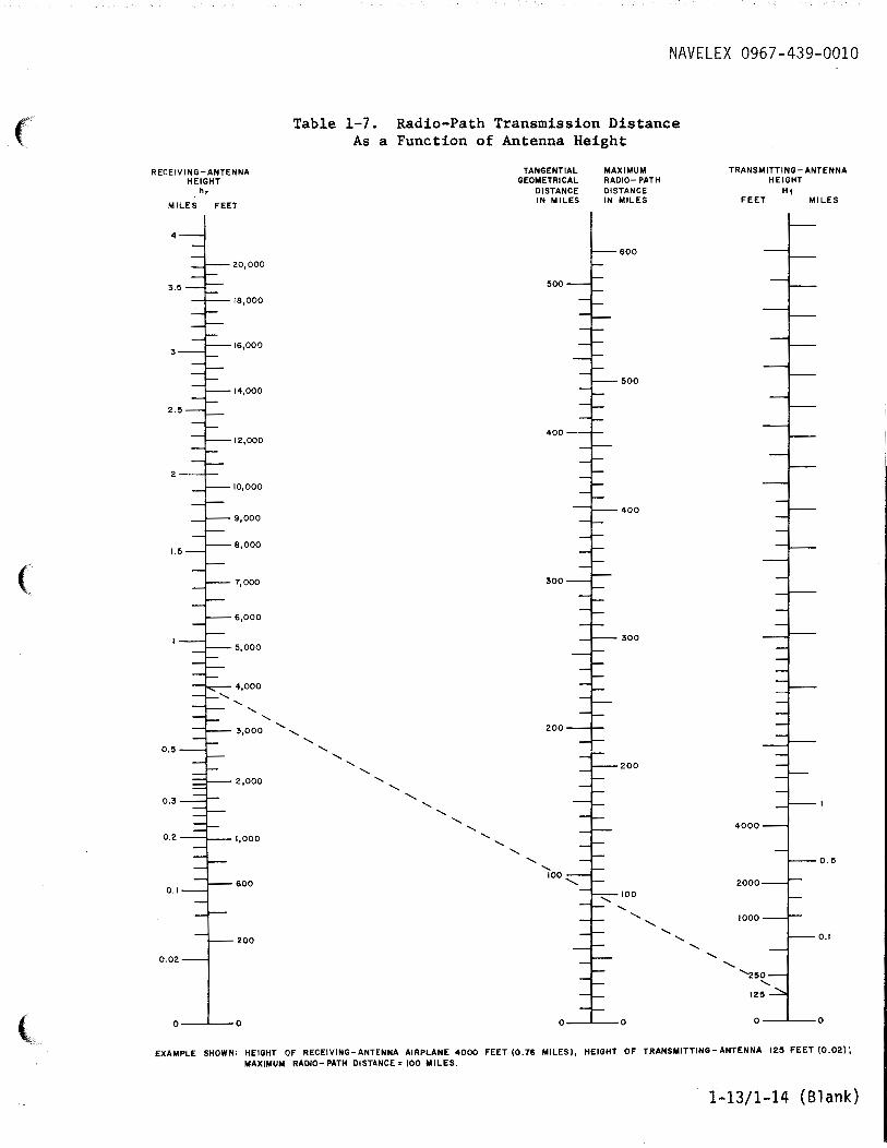
1-27. The transmission range of Radio Set AN/URC-9( ) is a function of the heights of the transmitting and receiving antennas. The monogram in table 1-7 provides the radio-path length and tangential distance for transmission between the transmitting and receiving equipment as a function of the heights of the antennas.
silica-gel desiccant. This package should then be placed in water-resistant carton and sealed. For final packaging, the ~quipment is ~laced in a wooden crate which is nailed closed.
CAUTION Whenever the radio is removed from service, the air-sealing plates must be placed over the louvers on the front of the power supply and on both sides of the radio case. During operation, the plates for the side ports are stored above the
1-28. PREPARATION FOR RESHIPMENT.
1-29. The reshipment preparation of Radio Set AN/URC-9( ) does not require any extraordinary precautions. The equipment should be placed in an air-coil padded carton with a sufficient amount of
ports against the sides of the case~ a~d the plates for the front panel are stored within the power supply behind the front panel.
1-11

NAVELEX 0967-439-0010
1-12
®
5
~
EQUIPMENT NOT SUPPLIED
PWR ON
~
SQUELCH DISABLE-
~ PUSH
(}) CONTROL, RADIO SET (})
I~ lt;;;;ll~·" I
~" ~,.==-''--- H
hi ~ E ~
RADIO SET CONTROL C-2383/URC-9
Figure 1-3. Radio Set Control C-2383/URC-9, Hard Wired Remote Control
EQUIPMENT NOT SUPPLIED
·"" ~CARRIER. ON
'DC 5
·e··. ··.7 " 2• I •a
,.
[6@ ~"'@ HANDSET MICROPHONE PHONES KEY
OR 0 CHESTSET TRANSMITTER
RADIO SET CONTROL C-1138/UR
r----- --- --- 7 ~ ~ ~ ~
~[·o .. D ··o[~ ~ LOI!!f\MOTE ~
ADAPTER ~ ON
~I}> ~
@@ ~ ~
CONTROL, ADAPTO~ MX-8430/URC-9
Q~l/
Figure 1-4. Typical Transmit Receive Control in the Standard 12 Wire Remote Control System
)
)
) "~;,:;
('
(
(,
NAVELEX 0967-439-0010
Table 1-7. Radio-Path Transmission Distance As a Function of Antenna Height
RECEIVING-ANTENNA TANGENTIAL MAXIMUM TRANSMITTING-ANTENNA HEIGHT GEOMETRICAL RADIO- PATH HEIGHT
hr DISTANCE DISTANCE Ht
MILES FEET IN MILES IN MILES FEET MILES
4-d
l---6oo 20,000
500
18,000
3~ 16,000
--=i=.--500 14,000
400 12,000
2--l-10,000
-=t,__400 9,000
8,000 '·"(
~7,000 300
6,000
:::J=___ 30 0 5,000
4,000
...... ......
3,000 ....... 200 .......
....... 0.5 -----l .......
....... ...... l---200 .......
2,000 ....... .......
0.3~ ........
....... .......
....... I 4000 .......
0.2 1,000 ....... .......
....... ....... --r- ,0.5
-==t_ 600 '=f;-~oo 2000
0.1
1000
....... l---0.1 200 --t_ .......
....... 0.02 . .......
0 0 0 0 0 0
EXAMPLE SHOWN; HEIGHT OF RECEIVING-ANTENNA AIRPLANE 4000 FEET (0.76 MILES), HEIGHT OF TRANSMITTING-ANTENNA 125 FEET (0.02); MAXIMUM RADIO- PATH DISTANCE= 100 MILES.
1-13/1-14 (Blank)
