radio wave propagation - k9vick9vic.info/files/classes/amateur extra propagation final 2013.pdfradio...
TRANSCRIPT

Radio Wave Propagation
Teach you enough to get all the propagation questions
right during the VE Session
Learn a few things from you about your experiences
Have fun
Finish everything on time (if not a little early)
Bob, KA9BH
Eric, K9VIC
Radio Wave Propagation
Teach you enough to get all the propagation questions
Learn a few things from you about your experiences
Finish everything on time (if not a little early)
Radio Wave Propagation
But first some leftovers from last week...
Radio Wave Propagation
But first some leftovers from last week...

The Smith Chart
Dr. Zachary Smith
The Smith Chart
Dr. Zachary Smith

The Smith Chart Resistance/conductance component at the
center.
Zero resistance at left
Infinite resistance at right
Reactance arcs above/below the center.
Inductive above (+1j
Capacitive below (
Standard (normalized) resistance at center of the chart.
SWR circles around center.
The Smith ChartResistance/conductance component at the
Zero resistance at left
Infinite resistance at right
Reactance arcs above/below the center.
Inductive above (+1j Ω at top center)
Capacitive below (-1j Ω at bottom center)
Standard (normalized) resistance at center of
SWR circles around center.

The Smith Chart What's it good for?
Used to portray complex impedances graphically
Can be used to solve for impedances when transformed through feedlines, etc.
Move clockwise around the chart from a load to the source
One wavelength is twice around the chart (e.g., ¼ wavelength would be ½ way around the circle)
Can be used for the open/shorted feedline questions.
The Smith Chart
Used to portray complex impedances
Can be used to solve for impedances when transformed through feedlines, etc.
Move clockwise around the chart from a load to
One wavelength is twice around the chart (e.g., ¼ wavelength would be ½ way around the
Can be used for the open/shorted feedline
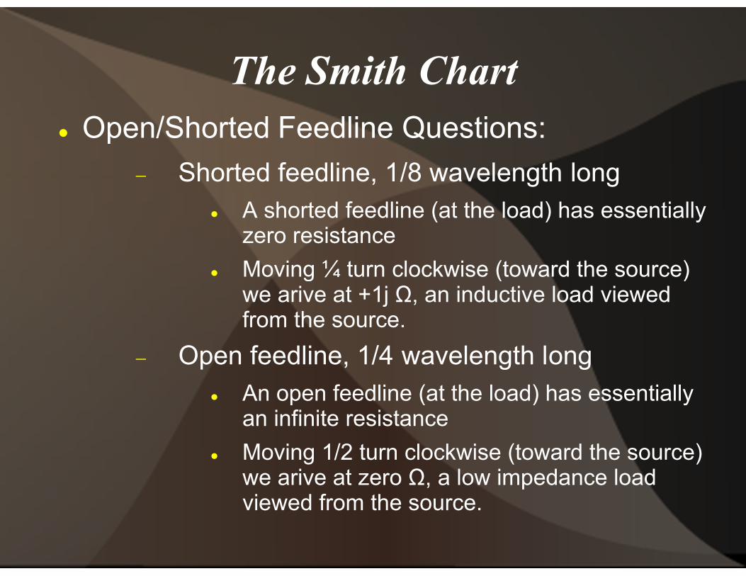
The Smith Chart Open/Shorted Feedline Questions:
Shorted feedline, 1/8 wavelength long A shorted feedline (at the load) has essentially
zero resistance
Moving ¼ turn clockwise (toward the source) we arive at +1j from the source.
Open feedline, 1/4 wavelength long An open feedline (at the load) has essentially
an infinite resistance
Moving 1/2 turn clockwise (toward the source) we arive at zero viewed from the source.
The Smith ChartOpen/Shorted Feedline Questions:
Shorted feedline, 1/8 wavelength longA shorted feedline (at the load) has essentially zero resistance
Moving ¼ turn clockwise (toward the source) we arive at +1j Ω, an inductive load viewed from the source.
Open feedline, 1/4 wavelength longAn open feedline (at the load) has essentially an infinite resistance
Moving 1/2 turn clockwise (toward the source) we arive at zero Ω, a low impedance load viewed from the source.
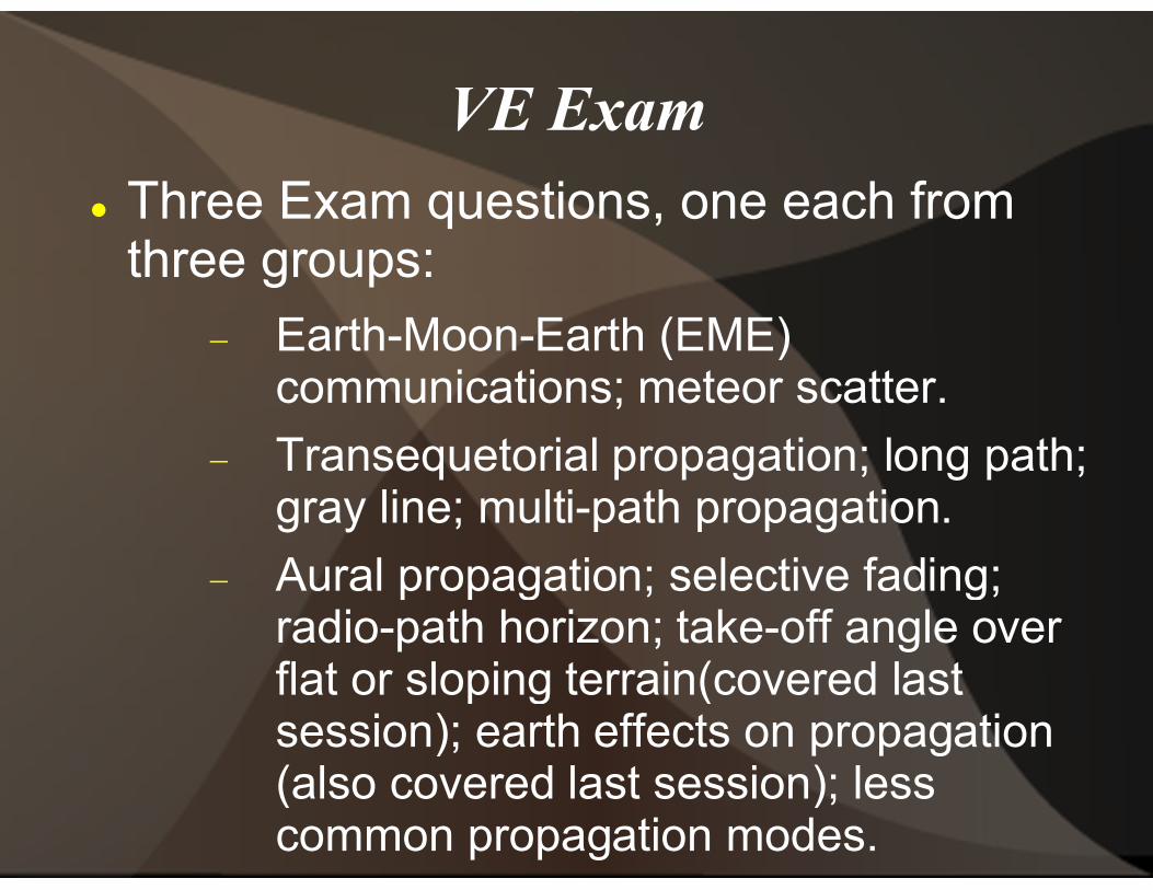
VE Exam Three Exam questions, one each from
three groups:
Earth-Moon-Earth (EME) communications; meteor scatter.
Transequetorial propagation; long path; gray line; multi-
Aural propagation; selective fading; radio-path horizon; takeflat or sloping terrain(covered last session); earth effects on propagation (also covered last session); less common propagation modes.
VE ExamThree Exam questions, one each from
Earth (EME) communications; meteor scatter.
Transequetorial propagation; long path; -path propagation.
Aural propagation; selective fading; path horizon; take-off angle over
flat or sloping terrain(covered last session); earth effects on propagation (also covered last session); less common propagation modes.
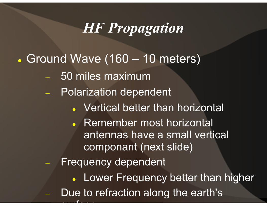
HF Propagation
Ground Wave (160 –
50 miles maximum
Polarization dependent
Vertical better than horizontal Remember most horizontal
antennas have a small vertical componant (next slide)
Frequency dependent
Lower Frequency better than higher
Due to refraction along the earth's surface
HF Propagation
– 10 meters)
50 miles maximum
Polarization dependent
Vertical better than horizontalRemember most horizontal antennas have a small vertical componant (next slide)
Frequency dependent
Lower Frequency better than higher
Due to refraction along the earth's

HF Propagation Ground Wave
HF Propagation
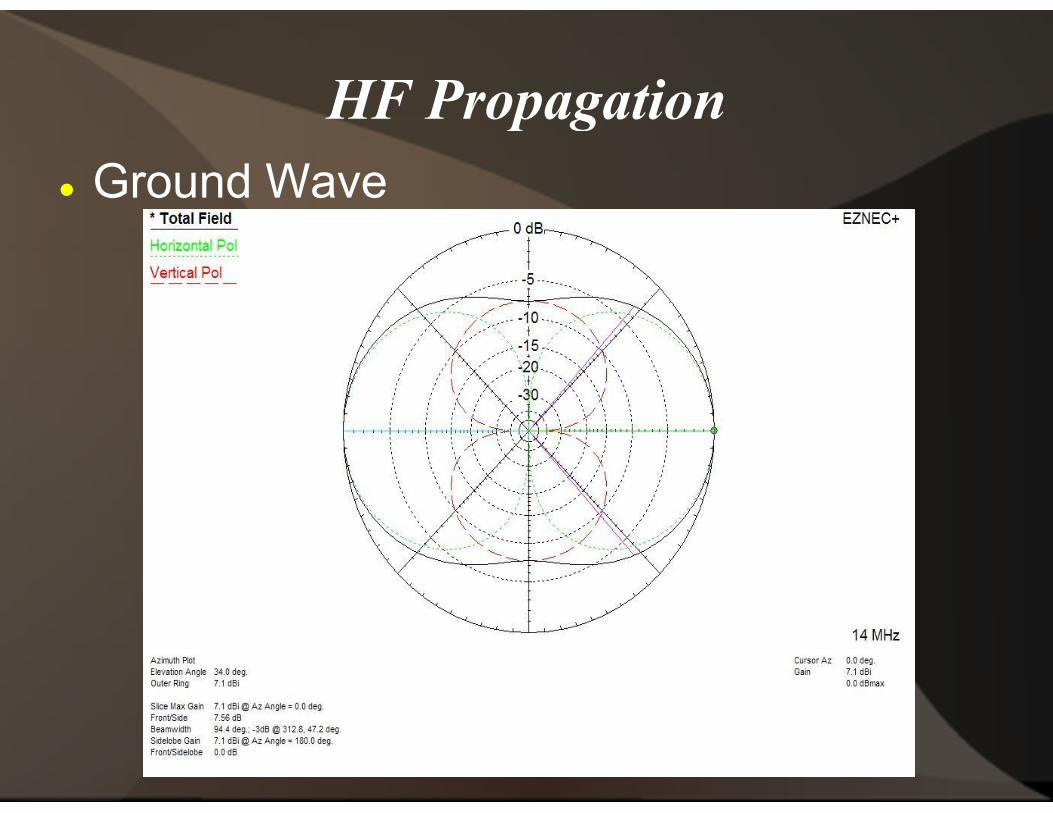
HF Propagation Ground Wave
HF Propagation

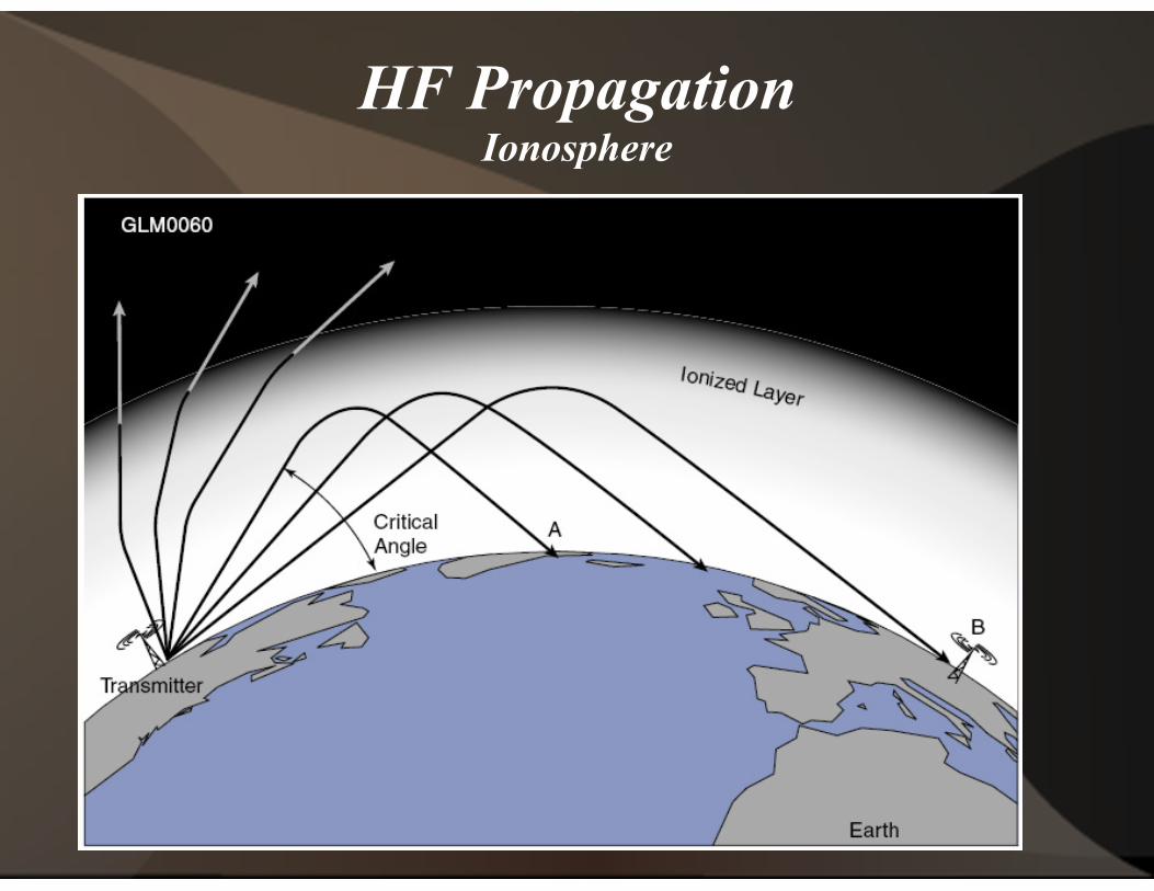
HF PropagationIonosphere
HF PropagationIonosphere

HF PropagationIonosphere
HF PropagationIonosphere

HF PropagationIonosphere
HF PropagationIonosphere

HF PropagationIonosphere
Critical Frequency
The highest frequency that will be returned to the earth when transmitted vertically under given ionospheric conditions
Critical Angle
The highest angle with respect to a vertical line at which a radio wave of a specified frequency can be propagated and still returned to the earth from the ionosphere
HF PropagationIonosphere
The highest frequency that will be returned to the earth when transmitted vertically under given ionospheric
The highest angle with respect to a vertical line at which a radio wave of a specified frequency can be propagated and still returned to the earth from the

HF PropagationIonosphere
Maximum Usable Frequency (MUF)
The upper frequency limit that canbe used for transmissions betweentwo points independent oftransmitter power.
HF PropagationIonosphere
Maximum Usable Frequency (MUF)
The upper frequency limit that canbe used for transmissions betweentwo points independent oftransmitter power.
HF PropagationIonosphere
HF PropagationIonosphere

HF PropagationIonosphere
Ionospheric Layer and Height(miles)
D Layer 30 - 60
E Layer 60 - 90
F1 Layer 140
F2 Layer 160 - 200
F Layer 160 - 200
HF PropagationIonosphere
Ionospheric Layer and Height Maximum Skip Distance(miles)
Absorbtive
1,400
Minimal Skip Affect
2,500
2,500

HF PropagationIonosphere
Long Path
Signal takes the longer of two great circle paths
Long path is 180
May hear both paths (echo)
Works on all HF bands (160 thru 10meters)
Very consistent on 20
HF PropagationIonosphere
Signal takes the longer of two great
Long path is 180° opposite short path
May hear both paths (echo)
Works on all HF bands (160 thru 10-
Very consistent on 20-meters

HF PropagationIonosphere
HF PropagationIonosphere

HF PropagationIonosphere
Sporadic E
Applies to VHF (or 10
50 MHz: 6000+ miles 144 MHz: 1900 miles
Strong cycle May, June, July
Lesser cycle December, early January
Independent of Solar Cycle
HF PropagationIonosphere
Applies to VHF (or 10-meters)
50 MHz: 6000+ miles144 MHz: 1900 miles
Strong cycle May, June, July
Lesser cycle December, early January
Independent of Solar Cycle
HF PropagationIonosphere
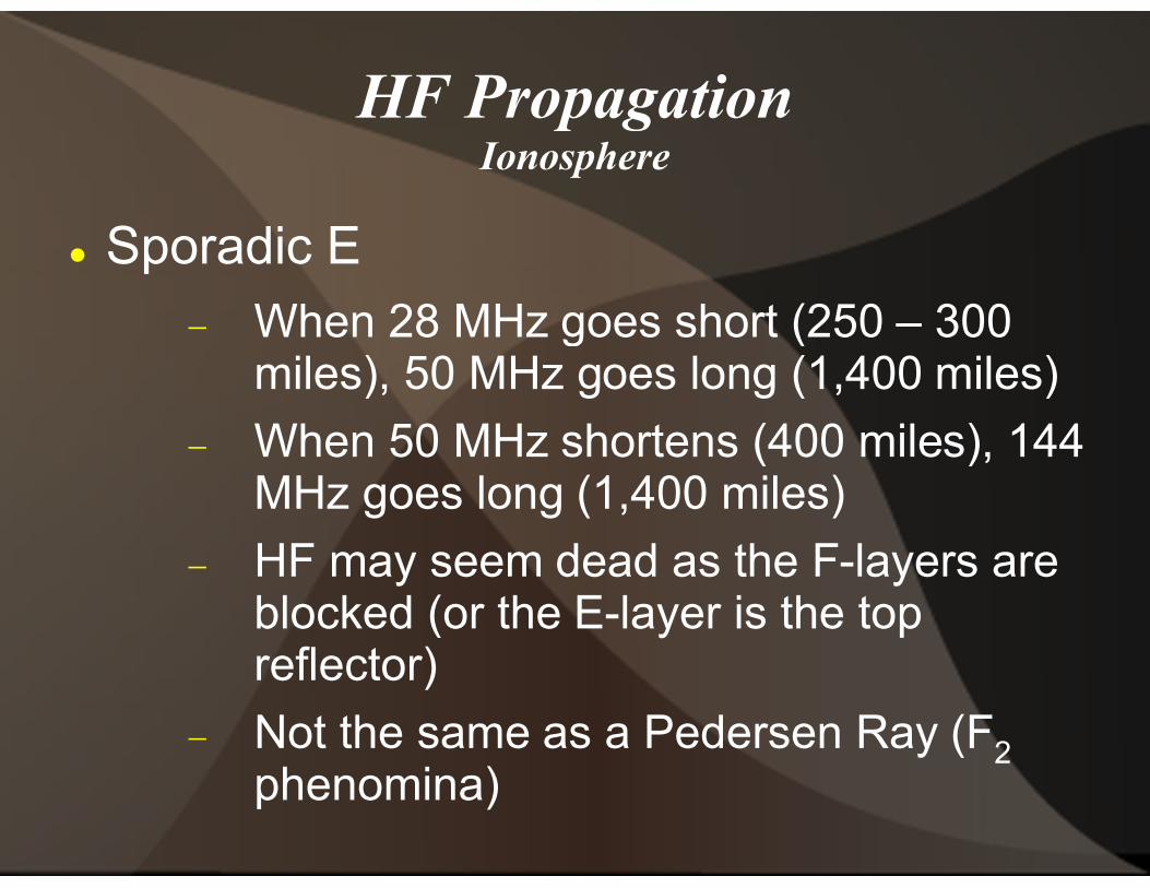
Sporadic E
When 28 MHz goes short (250 miles), 50 MHz goes long (1,400 miles)
When 50 MHz shortens (400 miles), 144 MHz goes long (1,400 miles)
HF may seem dead as the Fblocked (or the Ereflector)
Not the same as a Pedersen Ray (Fphenomina)
HF PropagationIonosphere
When 28 MHz goes short (250 – 300 miles), 50 MHz goes long (1,400 miles)
When 50 MHz shortens (400 miles), 144 MHz goes long (1,400 miles)
HF may seem dead as the F-layers are blocked (or the E-layer is the top
Not the same as a Pedersen Ray (F2
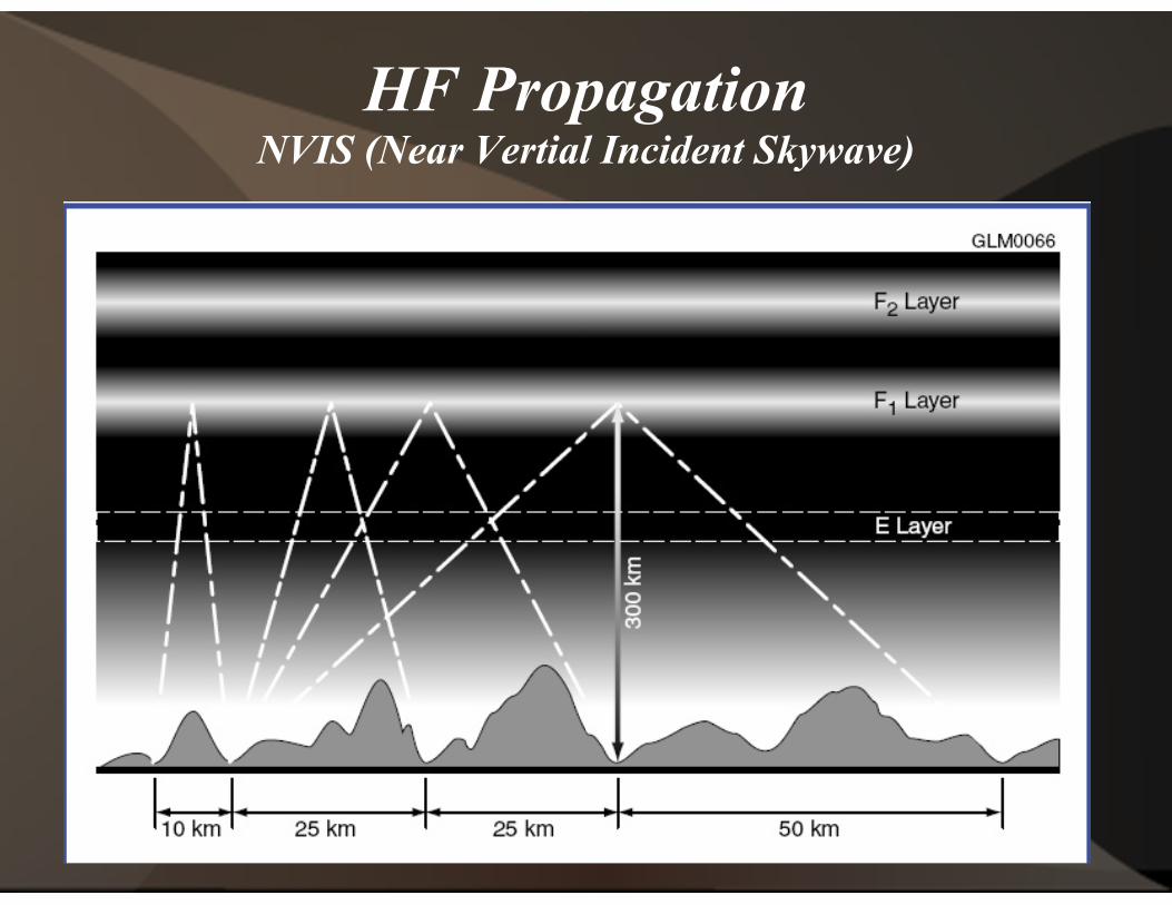
HF PropagationNVIS (Near Vertial Incident Skywave)
HF PropagationNVIS (Near Vertial Incident Skywave)

HF PropagationIonosphere (backscatter)HF PropagationIonosphere (backscatter)

HF PropagationIonosphere
Grayline Propagation
Occurs at daytime/nighttime terminator (twilight, sunset, sunrise)
D-layer quickly disappears or hasn't yet formed
F-layer is present
Skip is 8-10,000 miles on 3 or 4 HF bands
Always along Grayline (NOT one station in twilight, the other in darkness or light)
HF PropagationIonosphere
Grayline Propagation
Occurs at daytime/nighttime terminator (twilight, sunset, sunrise)
layer quickly disappears or hasn't yet
layer is present
10,000 miles on 3 or 4 HF
Always along Grayline (NOT one station in twilight, the other in darkness or light)
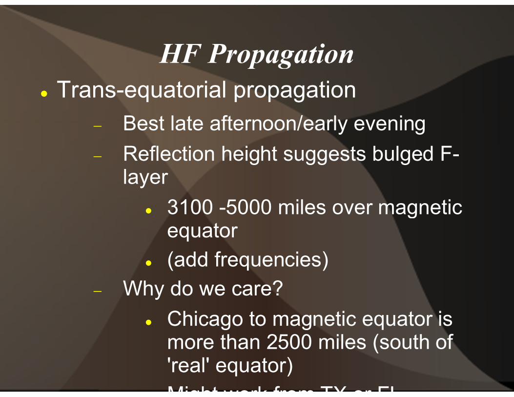
HF Propagation Trans-equatorial propagation
Best late afternoon/early evening
Reflection height suggests bulged Flayer
3100 -5000 miles over magnetic equator
(add frequencies) Why do we care?
Chicago to magnetic equator is more than 2500 miles (south of 'real' equator)Might work from TX or FL
HF Propagationequatorial propagation
Best late afternoon/early evening
Reflection height suggests bulged F-
5000 miles over magnetic
(add frequencies)Why do we care?
Chicago to magnetic equator is more than 2500 miles (south of 'real' equator)Might work from TX or FL

HF Propagation Selective Fading
Phase difference between components of a signal combine and cancel (generally due to multipath)
Large bandwidth are more effected
Phase band modes (even narrow band) are very succeptible
HF Propagation
Phase difference between components of a signal combine and cancel (generally due to multipath)
Large bandwidth are more effected
Phase band modes (even narrow band) are very succeptible

PropagationIonosphere
Meteor Scatter
Transmit using 15 second intervals
Popular modes:
Fast CW (100+ WPM)
WSJT
JT6
Best during meteor showers, and in the morning (heading into the shower)
Can be used any time with JT
PropagationIonosphere
Transmit using 15 second intervals
Fast CW (100+ WPM)
Best during meteor showers, and in the morning (heading into the shower)
Can be used any time with JT-modes

EME
Earth-Moon-Earth
Theoretically works for any two stations that can both see the moon (12,000 miles)
Frequencies Used:
144.000 - 144.100
432.000 - 432.100
Transmit 'schedule'
2-meters: 2 minutes on, 2 minutes listening
70-cm: 2.5 minutes on, 2.5 minutes listening
EME
Theoretically works for any two stations that can both see the moon (12,000 miles)
144.100
432.100
meters: 2 minutes on, 2 minutes listening
cm: 2.5 minutes on, 2.5 minutes listening
EME
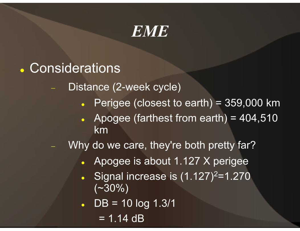
Considerations Distance (2-week cycle)
Perigee (closest to earth) = 359,000 km
Apogee (farthest from earth) = 404,510 km
Why do we care, they're both pretty far?
Apogee is about 1.127 X perigee
Signal increase is (1.127)(~30%)
DB = 10 log 1.3/1
= 1.14 dB
EME
week cycle)
Perigee (closest to earth) = 359,000 km
Apogee (farthest from earth) = 404,510
Why do we care, they're both pretty far?
Apogee is about 1.127 X perigee
Signal increase is (1.127)2=1.270
DB = 10 log 1.3/1

EME
Considerations
Moon's orbit is eliptical and tilted re: earth
Velocity not constant relative to earth
Allows 59% of the moon to be seen
41% of the far side (not dark) never seen
Libration Fading
Fluttery, irregular fading
EME
Moon's orbit is eliptical and tilted re:
Velocity not constant relative to
Allows 59% of the moon to be seen
41% of the far side (not dark) never
Libration Fading
Fluttery, irregular fading

EME Considerations
How do we increase s+n/n?
Bandwidth (cw, WSJT, JT65, etc.) ERP (amps, lots of aluminum)
Rx noise level (low noise rx a must)
EME
How do we increase s+n/n?
Bandwidth (cw, WSJT, JT65, etc.)ERP (amps, lots of aluminum)
Rx noise level (low noise rx a must)

VHF/UHFPropagation Troposhperic Ducting
Troposphere 0
Ducting products potential contacts of 500 miles
Due to radio horizon
Horizon =(2h)
Radio horizon ~15% farther than geometric horizon
Six miles = 31,680 feet, Horizon = 251.7 miles (double for two stations)
VHF/UHFPropagationTroposhperic Ducting
Troposphere 0 – 6 miles in height
Ducting products potential contacts of
Due to radio horizon
Horizon =(2h)1/2 h = haathorizon in miles
Radio horizon ~15% farther than geometric horizon
Six miles = 31,680 feet, Horizon = 251.7 miles (double for two stations)
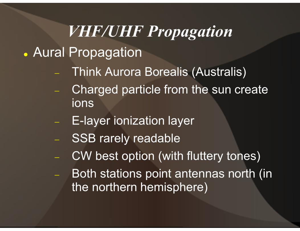
VHF/UHF Propagation Aural Propagation
Think Aurora Borealis (Australis)
Charged particle from the sun create ions
E-layer ionization layer
SSB rarely readable
CW best option (with fluttery tones)
Both stations point antennas north (in the northern hemisphere)
VHF/UHF Propagation
Think Aurora Borealis (Australis)
Charged particle from the sun create
layer ionization layer
SSB rarely readable
CW best option (with fluttery tones)
Both stations point antennas north (in the northern hemisphere)

VHF/UHF Propagation
Meteor Scatter
Meteor creates 12height
Propagation 500 –
Works on 28 to 144 MHz (50 MHz best bet)
Short lived:
30 seconds on 50 MHz
3 seconds on 144 MHz
<1 second on 432 MHz
VHF/UHF Propagation
Meteor creates 12-mile ion trail at E-layer
– 1400 miles
Works on 28 to 144 MHz (50 MHz best bet)
30 seconds on 50 MHz
3 seconds on 144 MHz
<1 second on 432 MHz
Radio Wave Propagation Questions?
Radio Wave Propagation