railway technical m catalogue - wordpress.com · and demonstrate that progress has been made with...
TRANSCRIPT

Railway noiseTechnical MeasuRes
caTalogue
May 2013Coordinator: nick cRaven
StEErinG Group: Jakob oeRTli (sbb), MaRTina FleckensTein (Db), FeRaT göçMen (Db), FRanck Poisson (sncF),Jan Hlaváček (vUZ) and Peter Hübner (UIC)
ConSultantS: FRank elbeRs & eDwin veRheiJen oF Dbvision

Railway noise Technical Measures Catalogue
International Union of Railways (UIC)
Final document

UIC Noise Technical Measures Catalogue | dBvision | 2/62
UIC003-01-04fe | 29 May 2013
Summary
There is a growing awareness of the impact of railway noise on public health, which has
resulted in pressure from line-side inhabitants, governments and health organizations for
increased noise mitigation. As a consequence, noise can be a limiting factor for many railway
operations, introducing additional costs for mitigation, demands for limits on
availability/capacity and resistance to expansion of the network.
Recent years have seen the development of new, and refinement of existing, strategies and
technologies for noise management. Railway companies often face calls to implement these,
and demonstrate that progress has been made with the use of new and innovative technology.
By collating best practice and case studies from "real life" tests and adding the theoretical
knowledge in this Catalogue, UIC stimulates the implementation of publically available
knowledge, demonstrate the progress that has been made and also manage stakeholder
expectations.
This Noise Technical Measures Catalogue surveys recent developments for three topics in
separate chapters:
1. Curve Squeal
2. Noise from freight marshalling yards
3. Noise from switches
In addition, one final chapter is dedicated to measures against rolling noise: rail and wheel
dampers, K and LL blocks, noise barriers and acoustic grinding.
Curve squeal
Curve squeal is a highly annoying sound that is radiated by trains running through sharp
curves. Much progress has been made during the past decades in understanding this
phenomenon. Mitigation measures aim at avoiding squeal events or at least reducing their
duration or strength. Flange lubrication and top-of-rail application of friction modifiers have
demonstrated to be very effective (reduction1: 5-20 dB(A)), provided that the dosing devices
receive constant and dedicated maintenance. Friction products can be applied from track-
based as well as vehicle-mounted devices and there are many manufacturers and suppliers of
such devices.
Special bogie designs, aiming at improved steering performance in curved as well as straight
track, also reduce squeal noise and are potential solutions for the future, provided that safety
issues can be solved adequately.
1 The ranges of noise reduction given in this summary always depend on the chosen reference situation.
UIC Noise Technical Measures Catalogue | dBvision | 3/62
UIC003-01-04fe | 29 May 2013
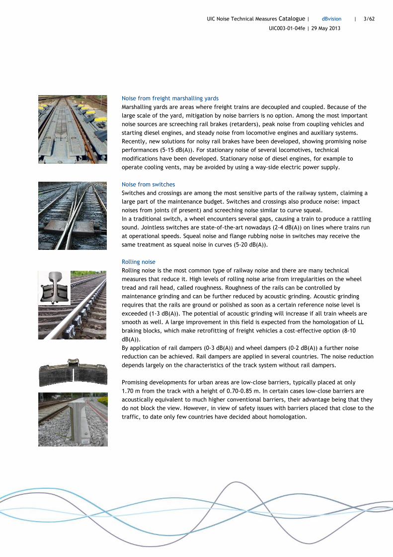
Noise from freight marshalling yards
Marshalling yards are areas where freight trains are decoupled and coupled. Because of the
large scale of the yard, mitigation by noise barriers is no option. Among the most important
noise sources are screeching rail brakes (retarders), peak noise from coupling vehicles and
starting diesel engines, and steady noise from locomotive engines and auxiliary systems.
Recently, new solutions for noisy rail brakes have been developed, showing promising noise
performances (5-15 dB(A)). For stationary noise of several locomotives, technical
modifications have been developed. Stationary noise of diesel engines, for example to
operate cooling vents, may be avoided by using a way-side electric power supply.
Noise from switches
Switches and crossings are among the most sensitive parts of the railway system, claiming a
large part of the maintenance budget. Switches and crossings also produce noise: impact
noises from joints (if present) and screeching noise similar to curve squeal.
In a traditional switch, a wheel encounters several gaps, causing a train to produce a rattling
sound. Jointless switches are state-of-the-art nowadays (2-4 dB(A)) on lines where trains run
at operational speeds. Squeal noise and flange rubbing noise in switches may receive the
same treatment as squeal noise in curves (5-20 dB(A)).
Rolling noise
Rolling noise is the most common type of railway noise and there are many technical
measures that reduce it. High levels of rolling noise arise from irregularities on the wheel
tread and rail head, called roughness. Roughness of the rails can be controlled by
maintenance grinding and can be further reduced by acoustic grinding. Acoustic grinding
requires that the rails are ground or polished as soon as a certain reference noise level is
exceeded (1-3 dB(A)). The potential of acoustic grinding will increase if all train wheels are
smooth as well. A large improvement in this field is expected from the homologation of LL
braking blocks, which make retrofitting of freight vehicles a cost-effective option (8-10
dB(A)).
By application of rail dampers (0-3 dB(A)) and wheel dampers (0-2 dB(A)) a further noise
reduction can be achieved. Rail dampers are applied in several countries. The noise reduction
depends largely on the characteristics of the track system without rail dampers.
Promising developments for urban areas are low-close barriers, typically placed at only
1.70 m from the track with a height of 0.70-0.85 m. In certain cases low-close barriers are
acoustically equivalent to much higher conventional barriers, their advantage being that they
do not block the view. However, in view of safety issues with barriers placed that close to the
traffic, to date only few countries have decided about homologation.

UIC Noise Technical Measures Catalogue | dBvision | 4/62
UIC003-01-04fe | 29 May 2013
Table of contents
Summary 2
1 Introduction 6
1.1 Collecting information 6 1.2 Cost of measures 6
2 Curve Squeal 8
Executive summary 8 2.1 Introduction 9 2.2 Technical description 9 2.3 Infrastructure measures 11 2.3.1 Track-mounted friction modifiers and lubrication devices 11 2.3.2 Asymmetrical rail transverse profile and gauge narrowing 16 2.4 Rolling stock measures 17 2.4.1 Vehicle-mounted friction modifiers and lubrication devices 17 2.4.2 Bogie design 20 2.5 References 20
3 Noise from freight marshalling yards 23
Executive summary 23 3.1 Introduction 23 3.2 Technical description 24 3.3 Infrastructure measures 25 3.3.1 Silent rail brakes (retarders) 25 3.4 Rolling stock measures 27 3.4.1 Idling noise 27 3.4.2 Impact noise from bumping and coupling vehicles 28 3.5 Operational measures 28 3.6 References 28
4 Noise from switches 30
Executive summary 30 4.1 Introduction 30 4.2 Technical description 31 4.3 Solutions 33 4.3.1 Jointless switches 33 4.3.2 Friction modifiers and lubrication 35 4.4 References 36

UIC Noise Technical Measures Catalogue | dBvision | 5/62
UIC003-01-04fe | 29 May 2013
5 Other noise measures 37
Executive summary 37 5.1 Introduction 37 5.2 Infrastructure measures 38 5.2.1 Rail dampers 38 5.2.2 Maintenance grinding and acoustic grinding 43 5.2.3 Low-close noise barriers 46 5.2.4 Noise barrier tops 51 5.3 Rolling stock measures 54 5.3.1 Wheel dampers 54 5.3.2 Braking blocks (K and LL) 56 5.4 References 60
Colophon 62

UIC Noise Technical Measures Catalogue | dBvision | 6/62
UIC003-01-04fe | 29 May 2013
1 Introduction
1.1 Collecting information
This catalogue is the result of an inventory and study of literature from various congress and
journals. The inventory took place in close cooperation with the UIC core group noise. Besides
this, many interviews were performed to acquire additional information, reports, references
to further publications, new projects, and information about practical experience.
The following railway noise experts were interviewed by telephone calls and e-mails,
between January and May 2013: Bernd Asmussen (DB), Bohumír Trávníček (SZDC), Brigita
Altenbaher (Elpa d.o.o.), Chris Jones (UK), Dave Anderson (RailCorp), David Thompson (ISVR),
Eduard Verhelst (Infrabel), Erkki Poikolainen (FTA), Ferat Göçmen (DB), Franck Poisson
(SNCF), Frans Slats (NS), Friedrich Krüger (STUVA), Günter Dinhobl (ÖBB), Jakob Oertli (SBB),
Jasper Peen (LRRE), Jens Nielsen (CHARMEC), Leo Baures (Bombardier), Lisette Mortensen
(Banedanmark), Margreet Beuving (Plurel), Markus Hecht (TU Berlin), Marta Ruiz Sierra (Adif),
Martin Müller (SBB), Michael Dittrich (TNO), Michael Pal (Perth), Nick Craven (Network Rail),
Nils Yntema (ProRail), Paul de Vos (DHV), Peter Hübner (UIC). Information was also received
by e-mail from certain suppliers and manufacturers.
Disclaimer: despite of all effort done to collect and interpret many measurement reports and
information from interviews of railway experts, neither the authors nor the UIC core group
noise can guarantee the performance of any product. The various lists of manufacturers and
suppliers are not exhaustive and they should not be seen as an endorsement.
1.2 Cost of measures
Noise measures are not for free. It is known that noise measures can have a significant impact
on cost for railways. A well-balanced noise mitigation strategy including life-cycle costs is
therefore important to keep the rail transport system competitive. Strategic decisions about
application of (new) noise measures should always be preceded by a cost-benefit assessment.
It can be difficult to determine relevant life-cycle costs (LCC), especially for innovative
products, of which some are included in this catalogue. But even with state-of-the-art
products, a good cost assessment is not simple.
Investment costs are sometimes presented with safety and track possession costs included,
sometimes these additional factors are excluded. Also, prices for labour, interest rate and
inflation differ between various countries and various years. This makes it hard to give exact

UIC Noise Technical Measures Catalogue | dBvision | 7/62
UIC003-01-04fe | 29 May 2013
figures for general installation and annual maintenance costs in a certain year. What seems
expensive in one country or situation can be affordable elsewhere. Also, comparison of costs
between vehicle-based and track-based measures with equal acoustic efficiency will be very
challenging, as these may depend both on the network length and on the rolling stock fleet
size.
Useful recent studies on cost of railway noise measures (in the public domain, internet) are:
• The real cost of railway noise mitigation - A risk assessment, De Vos and Van der Stap
(DHV), commissioned by UIC, 30 January 2013
• Innovative Maßnahmen zum Lärm- und Erschütterungsschutz am Fahrweg, Schlussbericht,
DB Netze, 15 June 2012
Apart from these studies, cost information in this catalogue is derived from certain test
reports cited in the respective chapters. In view of the complexity described above, in this
technical catalogue no attempt is made to convert cost information to a common basis, such
as Net Present Value or Equivalent Annual Costs, or to complete missing partial costs. It
should also be noted that the cost and lifetime figures in the Innovative Maßnahmen report
may refer to special cases and non-standard situations – for general purposes different figures
may be applicable.
The cost information cited in this catalogue can therefore be used as indicative cost.
UIC Noise Technical Measures Catalogue | dBvision | 8/62
UIC003-01-04fe | 29 May 2013
2 Curve Squeal
Executive summary
Curve squeal is a high-pitch sound that is radiated by trains running through sharp curves. The
wheels of a bogie or a two-axled vehicle are excited due to frictional instability when the
wheels are forced to follow the curve. The squealing sound corresponds to modes of wheel
vibration and is highly annoying because it is both loud and tonal. Much progress has been
made during the past decades in understanding the phenomenon, but it remains difficult to
predict whether a train will or will not produce this noise. This is because its occurrence
depends on a combination of many parameters.
In most countries curve squeal is not accounted for in their legal noise computation methods.
As a result, most noise maps do not include squeal noise. Treatment of curve squeal is usually
complaint-driven.
Most mitigation measures aim at avoiding squeal events or at least reducing their duration or
strength. Flange lubrication and top-of-rail application of friction modifiers have
demonstrated to be very effective (reduction: 5-20 dB(A)), provided that the dosing device
receives constant and dedicated maintenance. Friction products can be applied from track-
based as well as vehicle-mounted devices and there are many manufacturers and suppliers of
such devices. Special bogie designs, aiming at improved steering performance in curved and
tangent track, also reduce squeal noise and are potential solutions for the future. Wheel
dampers are known to reduce squeal noise as well.
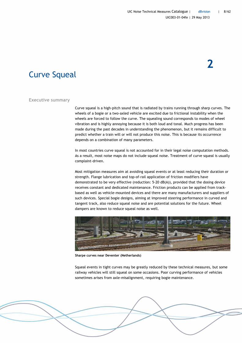
Sharpe curves near Deventer (Netherlands)
Squeal events in tight curves may be greatly reduced by these technical measures, but some
railway vehicles will still squeal on some occasions. Poor curving performance of vehicles
sometimes arises from axle-misalignment, requiring bogie maintenance.

UIC Noise Technical Measures Catalogue | dBvision | 9/62
UIC003-01-04fe | 29 May 2013
2.1 Introduction
It is generally difficult to predict whether a train will or will not produce squeal noise. It
depends on many parameters, like dry/rainy weather, tyre cross-section, curve radius, yaw
stiffness and bogie wheelbase. Because of this, the understanding of curve squeal has been
rather obscure for a long time. The squealing sound, which is radiated from the wheels,
corresponds to axial normal modes of vibration. The main tones appear at frequencies
between 250 Hz and 5 kHz [Thompson 2009]. Similar kinds of noise can occur in switches and
crossings, but these are usually associated with flange rubbing, see Chapter 4. Most mitigation
methods aim at avoiding the squeal noise or at least reducing its duration or strength.
In most countries curve squeal is not accounted for in their legal noise computation method.
A few countries apply a fixed curve squeal penalty expressed in dB(A) for sharp curves. Other
countries only account for squeal noise in industrial noise regulations, applicable for stabling
and marshalling yards.
The application of lubricants and friction modifiers on the rail, either by track-mounted or
vehicle-mounted systems, have demonstrated to be very effective. However, for a sustainable
solution against squeal noise these systems require constant and dedicated maintenance.
Special bogie designs may be able to avoid squeal as well. Anti-squeal railhead profiles and
gauge narrowing have also been tested, but have not proven successful in practical
implementations. Wheel dampers reduce squeal noise as well, though reducing curve squeal is
generally not the main incentive for application of wheel dampers.
2.2 Technical description
Squeal noise may occur while a rigid bogie or a two-axle railway vehicle is negotiating a
curve. Such vehicles have two parallel non-steerable axles, see Figure 1. While the wheels
will roll in the forward direction, the required lateral motion in curves can be realized
(partly) by the conicity of the wheel profile. In sharp curves additional lateral motion goes
along with lateral slip (frictional instability), causing the wheels to be excited and to squeal.
Parallel axles (rigid bogie or two-axle wagon) Steerable axles
Yaw angle
Figure 1 Top view of a curve with rigid bogie (left) and steerable axles (right)

UIC Noise Technical Measures Catalogue | dBvision | 10/62
UIC003-01-04fe | 29 May 2013
The understanding of the occurrence of squeal noise has involved extensive measurement and
modelling effort over the decades [Stappenbeck 1954, Rudd 1976, Périard 1998, Cataldi-
Spinola 2007, Othman 2009, Pieringer 2011, Krüger 2013]. Though it is now understood why
the leading inner wheel of a bogie is most likely to squeal, no model can fully predict squeal
events. Special vehicle, bogie and track design, based on continued applied research, can
possibly tackle the problem in the long run.
Due to the many parameters that have a large influence on the occurrence of squeal noise, an
international measurement standard to specify this type of noise and to determine the
effectiveness of measures against squeal, is still lacking. Defining a both useful and practical
test set-up, including a reference test curve, is a challenging problem. The Combating Curve
Squeal project financed by UIC [ERRI 2003, Oertli 2005] lead to useful practical knowledge on
testing procedures and possible measures. Under the recently started Acoutrain project (EC,
FP7) an attempt to define a measurement standard for curve squeal is being made.
It is customary to demonstrate the effect of measures against curve squeal graphically by
distributions of event noise levels (SEL, LAeq or LAFmax) before and after application of a certain
measure. This may be more meaningful than specifying an A-weighted noise reduction.
Lmax
Without friction modifier With friction modifier
Frequency of events
Figure 2 Effect of curve squeal can be represented by distribution graphs. Example of Berliner
Ringbahn, measured by Müller-BBM in Konjunkturprogamm II [DBNetze 2012].
The effect of curve squeal is usually not accounted for in national noise computation models.
The current version of German Schall03 includes a 3 dB(A) penalty for curves between 300
and 500 m radius that are known to produce squeal noise. The European method CNOSSOS
suggests adding 8 dB for R<300 m and 5 dB for 300 m<R<500 m to the rolling noise sound
power spectra for all frequencies.
UIC Noise Technical Measures Catalogue | dBvision | 11/62
UIC003-01-04fe | 29 May 2013
2.3 Infrastructure measures
2.3.1 Track-mounted friction modifiers and lubrication devices
Screeching problems in curves can be solved effectively by lubrication and application of
friction modifiers. The friction coefficient in the wheel/rail contact should not become too
low to avoid adhesion problems for traction and braking. Therefore, care is required with
certain lubricants or greases, as these may only be applied on the gauge corner of the rail and
on the wheel flange. Friction modifiers aim at controlling friction, rather than avoiding it,
and are developed to be also applied on top of the rail.
The usual goal to apply these products is reduction of wear and corrugation in curves and
switches, but as an important side–effect they avoid squeal and flanging noise.
Track-mounted systems can be considered state-of-the-art nowadays: wiping bars, drains and
water spraying. The friction modifier is to be applied on top of the head of the inner rail and
may also be applied between the wheel flange and gauge corner of the curve’s outer rail
[DBNetze 2012]. The wheels will spread the lubricant further along the curve. After many
axles have passed, the effective length of track were squeal is suppressed could be up to 200
meter [Nieuwenhuizen 2010]. Besides track-based systems, also vehicle-mounted systems
exist. Especially on locomotives they are state-of-the-art in many railways.
General observations
Experiences in several countries with different devices are listed below. A few general
conclusions can be drawn from them:
• Good field test results are important, but only proper maintenance of an application
system can make an investment a success in the long run. This means that maintenance
staff should be dedicated to avoid or clean clogged nozzles, to refill the tanks regularly,
to check if the fluid is well spread along the curve.
• Optimal dosing under various weather conditions requires attention and care.
• Poor curving performance, meaning that a vehicle does not gently move through a
curve, can also be a property of the vehicle. This would explain why certain vehicles will
still produce squeal noise, even if friction conditions in the curve are perfect.
• ‘Noise reduction’ is not the same as ‘annoyance reduction’, as residents living nearby
may still be annoyed by squeal noise in spite of good noise measurement results. This is
because lubricants or friction modifiers cause squeal events to occur less often, to have
a shorter duration, to be less intense, but hardly ever to vanish completely. The nature
of squeal noise (high pitch, loud, unpredictable) makes it hard to ignore.
Test examples and experience with track-mounted devices
A large number of field tests have been performed in various countries. Due to differences in
test conditions, friction products and application systems, measurement methods, and

UIC Noise Technical Measures Catalogue | dBvision | 12/62
UIC003-01-04fe | 29 May 2013
vehicles and curved tracks involved, test results will not be mutually comparable. The results
of the tests are summarized in Figure 3.
Figure 3 Summary of measured noise A-weighted reductions
- Tests at three railway stations in Bern and Zürich over 2005-2009 with Rail Partner
lubrication systems showed reasonable to considerable reductions of squeal events and
average noise levels [Krüger 2013]. In Bern (curve radius 180 m), the noise around 5 kHz
was attenuated by 11 dB and the average duration of squealing was reduced from 9 to 1
seconds. In Zürich-Airport (radius 480 m) the number of squealing events was cut by 30-
50%. In Zürich-Stadelhofen (350 m) the main noticeable effect was that the duration of
squeal events was halved. This did however not affect the overall noise level.
- The effects of three track-mounted lubrication systems have been evaluated during in
the German Konjunkturprogramm II [DB Netze 2012]. These systems were applied in
several curves with a radius beween 300 and 500 m. The systems under test were
anonimized. Results of system type 2 are shown in Figure 1 to the left. The red bars refer
to noise events measured before installation, the blue bars after installation. The
occurred maximum of peak levels is reduced by about 20 dB. An average noise reduction
is not reported, but the results satisfy the 3 dB(A) requirement of the current German
noise regulation2. Braking tests showed that the braking distance was not extended
unacceptably due to lubrication. Also, electrical circuit measurements revealed no
conflict with signalling requirements.
- Austrian Railways (ÖBB) have 600 track-side flange-lubricating devices in use for the
purpose of reduction of rail wear and to contribute to better LCC of the track. Noise
reduction is not a goal. Suppliers are Hy Power and Martin Schienentechnik. Top-of-rail
2 A new version of the Schall 03 regulation, with different prescriptions for curve squeal, is in preparation.
UIC Noise Technical Measures Catalogue | dBvision | 13/62
UIC003-01-04fe | 29 May 2013
devices from Hy Power (lubricant Sintono Terra HLK) are now being tested in Vienna and
Breitenstein.
- In Portugal noise measurements were carried out using the track-mounted system Elpa
CL-E1 with friction modifier KL-trinAI [Alarcão 2010]. The reduction effect of lubrication
varied between 3 to 10 dB(A), depending on the type of rolling stock. At frequencies
above 3 kHz, reductions up to 20 dB were found on average.
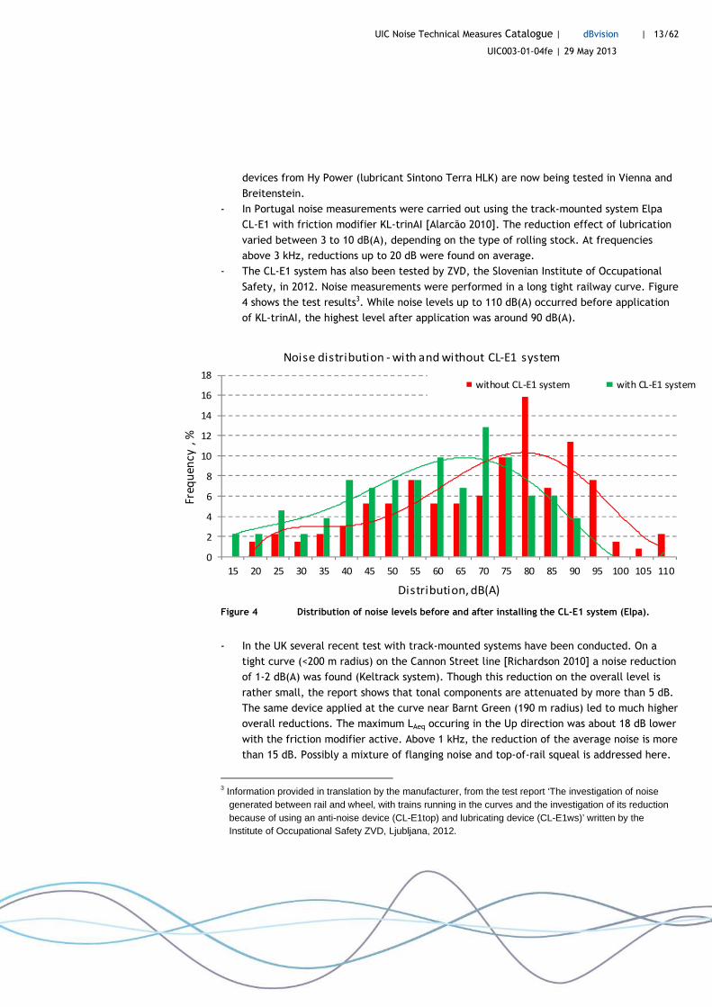
- The CL-E1 system has also been tested by ZVD, the Slovenian Institute of Occupational
Safety, in 2012. Noise measurements were performed in a long tight railway curve. Figure
4 shows the test results3. While noise levels up to 110 dB(A) occurred before application
of KL-trinAI, the highest level after application was around 90 dB(A).
0
2
4
6
8
10
12
14
16
18
15 20 25 30 35 40 45 50 55 60 65 70 75 80 85 90 95 100 105 110
Fre
qu
en
cy
, %
Distribution, dB(A)
Noise distribution - with and without CL-E1 system
without CL-E1 system with CL-E1 system
Figure 4 Distribution of noise levels before and after installing the CL-E1 system (Elpa).
- In the UK several recent test with track-mounted systems have been conducted. On a
tight curve (<200 m radius) on the Cannon Street line [Richardson 2010] a noise reduction
of 1-2 dB(A) was found (Keltrack system). Though this reduction on the overall level is
rather small, the report shows that tonal components are attenuated by more than 5 dB.
The same device applied at the curve near Barnt Green (190 m radius) led to much higher
overall reductions. The maximum LAeq occuring in the Up direction was about 18 dB lower
with the friction modifier active. Above 1 kHz, the reduction of the average noise is more
than 15 dB. Possibly a mixture of flanging noise and top-of-rail squeal is addressed here.
3 Information provided in translation by the manufacturer, from the test report ‘The investigation of noise
generated between rail and wheel, with trains running in the curves and the investigation of its reduction because of using an anti-noise device (CL-E1top) and lubricating device (CL-E1ws)’ written by the Institute of Occupational Safety ZVD, Ljubljana, 2012.

UIC Noise Technical Measures Catalogue | dBvision | 14/62
UIC003-01-04fe | 29 May 2013
Complaints by residents indicate that the lubrication system installed at Barnt Green is
only effective against squeal during short periods and certainly not during rainfall [Bailey
2013]. Barnt Green also has a long history with track-mounted water sprays. However,
this was considered a rather ineffective means to control squeal and also caused
problems with the track bed and the rails [Richardson 2009].
- At Fremantle Port in Perth (Australia), water spray is used in a tight railway curve . A 600
m long system sprays tap water 10 seconds before a train arrives. The results are
satisfactory and there is no need to use add substances to the water to improve friction.
In winter-time temperatures do not drop below 10 °C, so frost is no problem.
- Australian experience with curve squeal solutions shows that there are vehicles whose
poor curving performance is the main controlling factor, on which friction modifiers or
lubrication have hardly any effect [Anderson 2007]. Very slight axle misalignments may
be associated with poor curving performance. Evidence for this has been derived from
wayside angle-of-attack measurements and inspection in workshops . In that case proper
maintenance of the bogies is the only cost effective option. In certain curves squealing
only became a problem after the former track (timber sleepers, jointed rails) were
upgraded (concrete sleepers, continuously welded rail).
- In New Zealand [Apps 2012, Block 2012a, 2012b] test were conducted with Keltrack
‘Trackside Transit’ friction modifier on the Johnsonville Line. The test site was located in
curve with 200 m radius. The target friction coefficient of the substance is 0.35. For the
test, the product was manually applied on top of the rail using paint rollers, while
normally an automatic track-based device is to be used. The test results were promising.
Maximum peak levels were reduced by 12 dB(A). Squealing events were reduced
significantly. After a variable number of trains had passed, the squealing started again. It
was recommended to optimize the frequency of application of the friction modifier.
Cost
The indicative cost of track-mounted friction modifier devices is given in Table 1. Cost refers
to one system, which on average controls approximately 480 m of (curved) track.
Table 1 Indicative cost of track-mounted friction modifier devices.
Noise measure Source Country Cost per unit
Life time [years]
Investment [x1000 euro]
Additional annual [x1000 euro]
Track-based system friction modifier
DB, KP-II Germany per system 13 25,7 5,0
UIC Noise Technical Measures Catalogue | dBvision | 15/62
UIC003-01-04fe | 29 May 2013
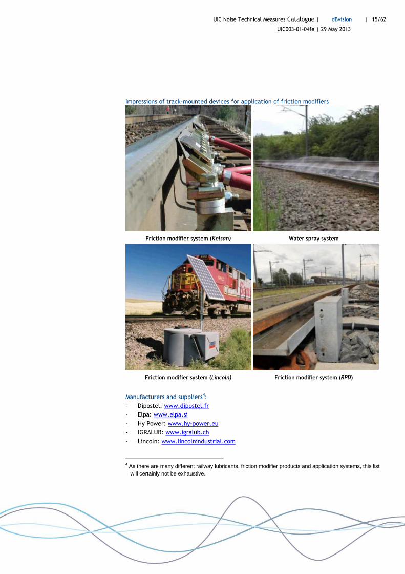
Impressions of track-mounted devices for application of friction modifiers
Friction modifier system (Kelsan) Water spray system
Friction modifier system (Lincoln) Friction modifier system (RPD)
Manufacturers and suppliers4:
- Dipostel: www.dipostel.fr
- Elpa: www.elpa.si
- Hy Power: www.hy-power.eu
- IGRALUB: www.igralub.ch
- Lincoln: www.lincolnindustrial.com
4 As there are many different railway lubricants, friction modifier products and application systems, this list
will certainly not be exhaustive.

UIC Noise Technical Measures Catalogue | dBvision | 16/62
UIC003-01-04fe | 29 May 2013
- Lubricant Consult: www.lubcon.com
- Martin Schienentechnik: www.martin-schienentechnik.com
- MBM Industry & Rail Tech: www.mbm-industrietechnik.at
- Portec Rail Products and Kelsan: www.lbfoster-railtechnologies.com
- QHi Rail: www.qhirail.com
- Rail Partner Deutschland: www.railpartnerdeutschland.de
- REBS Zentralschmiertechnik: www.rebs.de
- Vesconite Hilube: www.vesconite.com
2.3.2 Asymmetrical rail transverse profile and gauge narrowing
Asymmetrical rail profiles and/or slightly narrower track gauges have been proposed against
wear in curves. The basic idea is that the contact position on the inside wheel is shifted
nearer the flange, thus improving the rolling radius difference of the wheelset. This way, the
bogie is caused to traverse the curve more gently [Thompson 2009].
Their effect on curve squeal has been tested in different countries. A pilot study in
Switzerland over 2005-2006 disappointingly showed only positive effects for one type of
passenger train [Krüger 2013]. A special anti-squeal design [Dirks 2007, Hiensch 2007] has
been tested in a curve (200 m radius) near The Hague [Hiensch 2010]. Though the profile did
not reduce the number of squeal events, the average LAeq per squeal event was 3 dB lower
than before the test. A second test section with the same profile, of which the inner rail had
been impregnated with tungsten carbide (WC), was capable of reducing the number of squeal
events from 74% to 26%. The average LAeq of the squeal events was reduced by 4 dB. However,
the wear rate of this sample rail did not meet requirements of sustainability. Also, due to the
need to grind away corrugation in the long run, the metal particle impregnation would need
to be renewed every five years.
Figure 5 Asymmetrical rail head profile [Hiensch 2007]. WC impregnation [Hiensch 2010].
A slightly narrower gauge than standard will shift the contact patch position of wheel and
rail. Positive results were reported from tram systems.
UIC Noise Technical Measures Catalogue | dBvision | 17/62
UIC003-01-04fe | 29 May 2013
2.4 Rolling stock measures
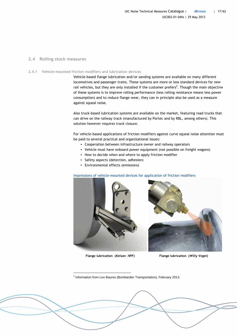
2.4.1 Vehicle-mounted friction modifiers and lubrication devices
Vehicle-based flange lubrication and/or sanding systems are available on many different
locomotives and passenger trains. These systems are more or less standard devices for new
rail vehicles, but they are only installed if the customer prefers5. Though the main objective
of these systems is to improve rolling performance (less rolling resistance means less power
consumption) and to reduce flange wear, they can in principle also be used as a measure
against squeal noise.
Also truck-based lubrication systems are available on the market, featuring road trucks that
can drive on the railway track (manufactured by Portec and by RBL, among others). This
solution however requires track closure.
For vehicle-based applications of friction modifiers against curve squeal noise attention must
be paid to several practical and organizational issues:
• Cooperation between infrastructure owner and railway operators
• Vehicle must have onboard power equipment (not possible on freight wagons)
• How to decide when and where to apply friction modifier
• Safety aspects (detection, adhesion)
• Environmental effects (emissions)
Impressions of vehicle-mounted devices for application of friction modifiers
Flange lubrication (Kelsan HPF) Flange lubrication (Willy Vogel)
5 Information from Leo Baures (Bombardier Transportation), February 2013.
UIC Noise Technical Measures Catalogue | dBvision | 18/62
UIC003-01-04fe | 29 May 2013
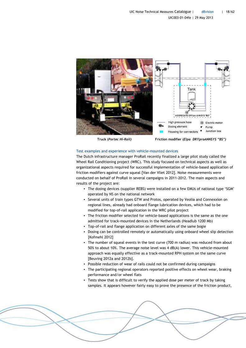
Truck (Portec Hi-Rail) Friction modifier (Elpa DRYproANNSYS “BS”)
Test examples and experience with vehicle-mounted devices
The Dutch infrastructure manager ProRail recently finalized a large pilot study called the
Wheel Rail Conditioning project (WRC). This study focused on technical aspects as well as
organizational aspects required for successful implementation of vehicle-based application of
friction modifiers against curve squeal [Van der Vliet 2012]. Noise measurements were
conducted on behalf of ProRail in several campaigns in 2011-2012. The main aspects and
results of the project are:
• The dosing devices (supplier REBS) were installed on a few EMUs of national type ‘SGM’
operated by NS on the national network
• Several units of train types GTW and Protos, operated by Veolia and Connexxion on
regional lines, already had onboard flange lubrication devices, which had to be
modified for top-of-rail application in the WRC pilot project
• The friction modifier selected for vehicle-based applications is the same as the one
admitted for track-mounted devices in the Netherlands (Headlub 1200 Mb)
• Top-of-rail and flange application on different axles of the same bogie
• Dosing can be controlled remotely or automatically using onboard wheel slip detection
[Kofmehl 2012]
• The number of squeal events in the test curve (700 m radius) was reduced from about
50% to about 10%. The average noise level was 4 dB(A) lower. This vehicle-mounted
approach was equally effective as a track-mounted RPH system on the same curve
[Beuving 2012a and 2012b].
• Possible reduction of wear of rails could not be confirmed during campaigns
• The participating regional operators reported positive effects on wheel wear, braking
performance and/or wheel flats
• Tests show that is difficult to verify the applied dose per meter of track by taking
samples. It appears however fairly easy to prove the presence of the friction product,

UIC Noise Technical Measures Catalogue | dBvision | 19/62
UIC003-01-04fe | 29 May 2013
by spraying some water on the top of the rail, which clearly forms pearls [Beuving
2012a].
Impressions of vehicle-mounted devices in WRC project
flange
Top of rail
Flange application of friction modifier TOR application of friction modifier
Cost
Indicative cost of vehicle-mounted friction modifier devices is given in Table 2.
Table 2 Indicative cost of vehicle-mounted friction modifier devices.
Noise measure Source Country Cost per unit
Life time [years]
Investment [x1000 euro]
Additional annual [x1000 euro]
Vehicle-based system friction modifier
ProRail, WRC Netherlands per train 15 20,0 3,6
Manufacturers and suppliers:
- Elpa: www.elpa.si
- Portec Rail: www.PortecRail.com (truck-based)
- Rail Partner Deutschland: www.railpartnerdeutschland.de
- REBS Zentralschmiertechnik: www.rebs.de
- Robolube: www.rblinc.com (truck-based)
- Vesconite Hilube: www.vesconite.com
- Willy Vogel AG: www.vogelag.com
UIC Noise Technical Measures Catalogue | dBvision | 20/62
UIC003-01-04fe | 29 May 2013
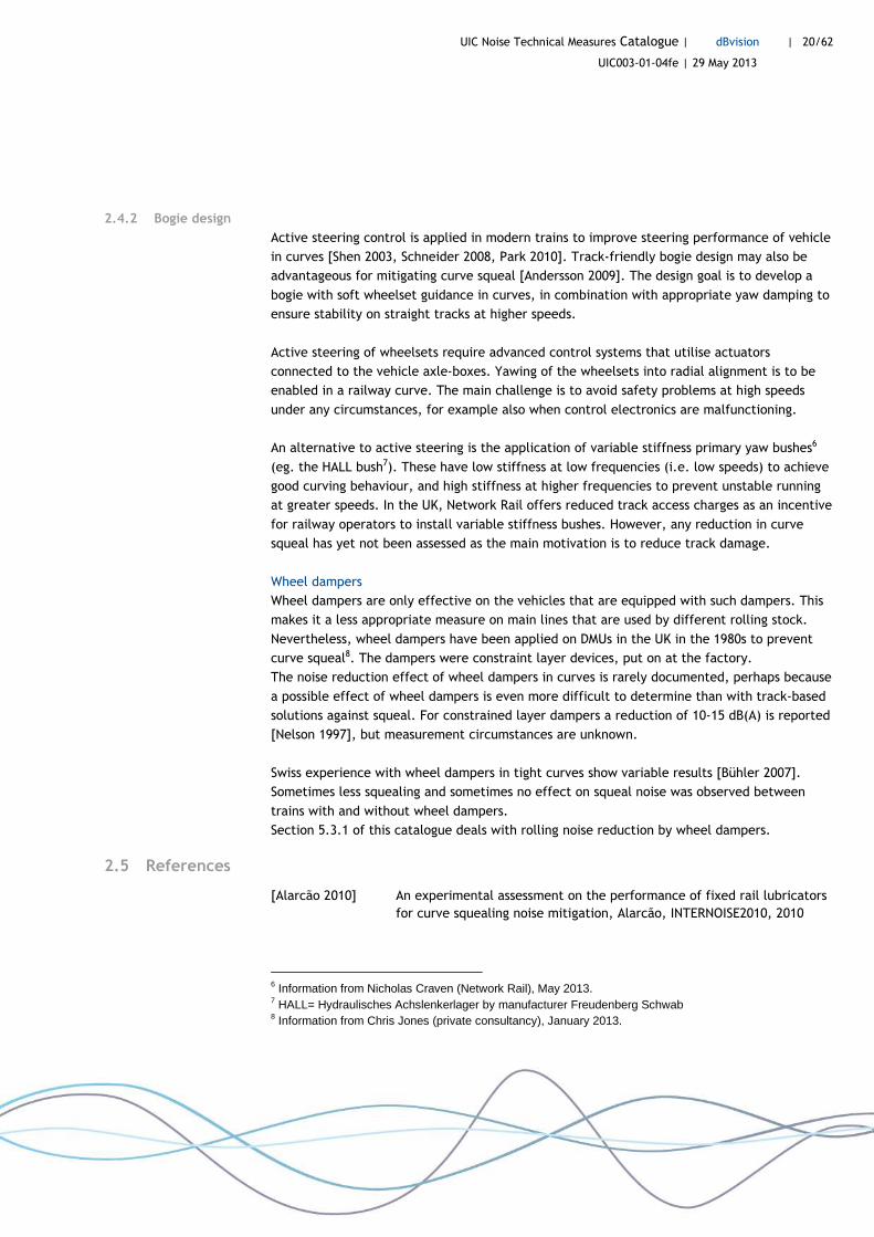
2.4.2 Bogie design
Active steering control is applied in modern trains to improve steering performance of vehicle
in curves [Shen 2003, Schneider 2008, Park 2010]. Track-friendly bogie design may also be
advantageous for mitigating curve squeal [Andersson 2009]. The design goal is to develop a
bogie with soft wheelset guidance in curves, in combination with appropriate yaw damping to
ensure stability on straight tracks at higher speeds.
Active steering of wheelsets require advanced control systems that utilise actuators
connected to the vehicle axle-boxes. Yawing of the wheelsets into radial alignment is to be
enabled in a railway curve. The main challenge is to avoid safety problems at high speeds
under any circumstances, for example also when control electronics are malfunctioning.
An alternative to active steering is the application of variable stiffness primary yaw bushes6
(eg. the HALL bush7). These have low stiffness at low frequencies (i.e. low speeds) to achieve
good curving behaviour, and high stiffness at higher frequencies to prevent unstable running
at greater speeds. In the UK, Network Rail offers reduced track access charges as an incentive
for railway operators to install variable stiffness bushes. However, any reduction in curve
squeal has yet not been assessed as the main motivation is to reduce track damage.
Wheel dampers
Wheel dampers are only effective on the vehicles that are equipped with such dampers. This
makes it a less appropriate measure on main lines that are used by different rolling stock.
Nevertheless, wheel dampers have been applied on DMUs in the UK in the 1980s to prevent
curve squeal8. The dampers were constraint layer devices, put on at the factory.
The noise reduction effect of wheel dampers in curves is rarely documented, perhaps because
a possible effect of wheel dampers is even more difficult to determine than with track-based
solutions against squeal. For constrained layer dampers a reduction of 10-15 dB(A) is reported
[Nelson 1997], but measurement circumstances are unknown.
Swiss experience with wheel dampers in tight curves show variable results [Bühler 2007].
Sometimes less squealing and sometimes no effect on squeal noise was observed between
trains with and without wheel dampers.
Section 5.3.1 of this catalogue deals with rolling noise reduction by wheel dampers.
2.5 References
[Alarcão 2010] An experimental assessment on the performance of fixed rail lubricators for curve squealing noise mitigation, Alarcão, INTERNOISE2010, 2010
6 Information from Nicholas Craven (Network Rail), May 2013. 7 HALL= Hydraulisches Achslenkerlager by manufacturer Freudenberg Schwab 8 Information from Chris Jones (private consultancy), January 2013.

UIC Noise Technical Measures Catalogue | dBvision | 21/62
UIC003-01-04fe | 29 May 2013
[Anderson 2007] Mitigation of Wheel Squeal and Flanging Noise on the Australian Rail Network, Anderson, IWRN2007, 2007
[Andersson 2009] On the optimization of a track-friendly bogie for high speed, Andersson, IASVD-09, 2009
[Apps 2012] Matangi Curve Noise Solution; Step 2 Solutions Proposal, Apps, Greater Wellington Rail Limited, 2012
[Bailey 2013] Barnt Green Rail Noise, Bailey, Residents, 2013
[Beuving 2012a] Paraplurapport 4; Eindrapport Pilot WielRailConditionering; Meetresultaten, Beuving, DeltaRail, 2012
[Beuving 2012b] Booggeluidreductie bij lagere Wiel-Railadhesie, Beuving, DeltaRail, 2012
[Block 2012a] Curve Squeal on the Johnsonville Line Step 1 Noise study, Block, Lloyd's Register Rail, 2012
[Block 2012b] Curve Squeal on the Johnsonville Line Step 2 Friction modifier test, Block, Lloyd's Register Rail, 2012
[Bühler 2007] How to avoid squeal noise on railways - State of the art and practical experience, Bühler, IWRN2007, 2007
[Cataldi-Spinola 2005] Curve squaling of railroad vehicles, Cataldi-Spinola, ETH Zurich, 2005
[DBNetze 2012] Innovative Maßnahmen zum Lärm- und Erschütterungsschutz am Fahrweg, DB Netze, 2012
[Dirks 2007] Asymmetric rail profile to prevent railway squeal noise, Dirks, Internoise, 2007
[DHV 2013b] The real cost of railway noise mitigation - A risk assessment, DHV, commissioned by UIC, 2013
[ERRI 2003] Combating Curve Squeal Phase I, ERRI, ERRI, 2003
[Hiensch 2007] Rail head optimisation to reach a sustainable solution preventing railway squeal noise, Hiensch, DeltaRail, 2007
[Hiensch 2010] Anti squeal fieldtest, Hiensch, DeltaRail, 2010
[Kofmehl 2012] Gaining approval for railhead conditioning, Kofmehl, Eurailnag27, 2012
[Krüger 2013] Kurvengeräusche - Messung, Bewertung und Minderungsmaßnahmen, Krüger, Erich Schmidt Verlag, 2013
[Nelson 1997] Wheel-rail noise control manual TCRP Report 23, Nelson, WI&A, 1997
[Nieuwenhuizen 2010] Aanpak booggeluid op emplacementen; Stand van zaken drie typen brongerichte maatregelen, Nieuwenhuizen, MBBM, 2010
[Oertli 2005] Combating Curve Squeal Phase II, Oertli, UIC, 2005
[Othman 2009] Kurvenquietschen: Untersuchung des Quietschvorgangs und Wege der Minderung, Othman, Technische Universität Berlin, 2009
[Park 2010] Design and analysis of an active steering bogie for urban trains, Park, Journal of Mechanical Science and Technology (24), 2010
[Périard 1998] Wheel-noise generation: curve squealing by trams, Périard, TU Delft, 1998

UIC Noise Technical Measures Catalogue | dBvision | 22/62
UIC003-01-04fe | 29 May 2013
[Pieringer 2011] Time-domain modelling of high-frequency wheel/rail interaction, Pieringer, Chalmers universi ty of technology, 2011
[Richardson 2009] Acoustic Trial of Kelsan Friction Modifier at Barnt Green, Richardson, Network Rail, 2009
[Richardson 2010] Acoustic Trial of Kelsan Friction Modifier at Southwark Cathedral, Richardson, Network Rail, 2010
[Rudd 1976] Wheel rail noise - Part II: Wheel squeal, Rudd, Journal of Sound and Vibration, 46(3):381–394, 1976
[Schneider 2008] Active Radial Steering and Stability Control with the Mechatronic Bogie, Schneider, Bombardier Transportation, 2008
[Shen 2003] Active Steering of Railway Vehicles a Feedforward Strategy, Shen, University of Leeds, 2003
[Stappenbeck 1954] Das Kurvengeräusch der Straßenbahn - Möglichkeiten zu seiner Unterdrückung, Stappenbeck, VDI Zeitschrift, 96(6):171–175, 1954
[Thompson 2009] Railway Noise and Vibration-Mechanisms, Modelling and Means of Control, Thompson, Elsevier (Oxford), 2009
[Van der Vliet 2012] Eindrapportage Wiel Rail Conditionering, Van der Vliet, ProRail, 2012

UIC Noise Technical Measures Catalogue | dBvision | 23/62
UIC003-01-04fe | 29 May 2013
3 Noise from freight marshalling yards
Executive summary
Marshalling yards are areas where freight trains are formed and the freight wagons are
decoupled and coupled. Various noisy activities take place on different periods of the day and
on different areas of the yard. Because of the large scale of the yard, mitigation by noise
barriers is no option. Measures can only be taken at the source. The most important noise
sources are high-pitch curve and switch squeal and screeching brakes. Also impact sounds
from coupling vehicles are of concern and starting (diesel) locomotive engines can be heard.
Perhaps the most annoying sources on the yards are the rail brakes (retarders), for which new
technical solutions have been developed with promising noise performances (5-15 dB(A)). For
idling noise, caused by (diesel) locomotives running stationary, different measures are
proposed for different types of locomotives. Operational mitigation measures may also be an
option, but practical experience with the proposals are not available.
Marshalling yard of Nuremberg Aerial photo from Bing Maps
3.1 Introduction
Marshalling yards (French gares de triage, German Rangierbahnhöfe) are areas were freight
trains are split up and sorted out. Many marshalling yards were originally built far away from
UIC Noise Technical Measures Catalogue | dBvision | 24/62
UIC003-01-04fe | 29 May 2013
dwellings, but due to urbanization they often find themselves surrounded by residential areas
now. Various sources of noise can be identified at marshalling yards: rolling noise, traction
noise, stationary noise from idling diesel locomotives, flanging noise, noise of switches and
impact noise from (de)coupling.
In most countries regulations for industrial noise apply to yard operations. Besides the
requirements to fulfill noise limits, also the need to handle complaints from residents are
incentives to reduce noise from marshalling yards.
3.2 Technical description
In principle, the marshalling process can be done by shunting locomotives that run to and fro.
The wagons are collected on one side of the yard and are coupled to compose a new train on
the other side.
However, more often gravity is used to do the sorting. For this purpose either a man-made
hill, the hump, is used or the whole yard is built on a slope. A locomotive pushes a string of
freight wagons to the top of the hump where the wagons are uncoupled, (mostly) one by one.
Each wagon is given sufficient momentum to roll towards the so-called classification track to
form a new train. On its way, it will pass switches and often also a retarder (rail brake) to
slow down the wagon’s speed. If the speed is too low to reach the tail of the new train, a
conveyor (German Förderanlage) is used to carry the wagon further.
Hot spot identification
Before a noise mitigation programme can be started on a marshalling yard, one has to
determine which sources are contributing most, and also when and where. On a large yard,
this is not a simple task. There are different approaches to hot spot identification.
One approach is to do interviews with yard staff in order to determine all relevant processes.
The source strenght of noisy activities can be assessed by measurements or by making use of
existing noise source databases, for example as delivered by the IMAGINE project [IMAGINE
2006].
Another approach is using unmanned noise monitoring stations in combination with advanced
signal processing. For example, the TNO Andante system is capable of making a both spatial
and temporal identification of hot spots on a large area with multiple noise sources [TNO
2008]. Noise events outside the yard area are excluded automatically. Noise events inside the
yard are recorded for playback, if desired.
The next step is to develop a mitigation plan adapted to the findings. In the SILENCE project,
a innovative approach towards ‘depots and shunting yards’ has been developed [Beuving
2007]. Instead of a focus on noise levels, it may be more effective to reduce annoyance. To
this end, a ranking can be made of the annoyance of various noise events. Though the
SILENCE approach concentrates on stabling yards (passenger trains) rather than freight
marshalling yards, the methodology is basically the same.

UIC Noise Technical Measures Catalogue | dBvision | 25/62
UIC003-01-04fe | 29 May 2013
3.3 Infrastructure measures
3.3.1 Silent rail brakes (retarders)
A vehicle passing a rail brakes will in general produce a screeching type of noise, similar to
curve squeal. As there are various types of rail brakes, a single solution is not available.
In the Czech Republic, special rail brake systems by the Slovenian company Elpa were tested
at the yards Havlíčkův Brod [Hlaváček 2012] and Brno-Maloměřice [Hlaváček 2010]. On both
sites the system Bremex-Ansyss has been installed. This system is designed to reduce wear as
well as screeching noise through the use of a lubricant. The noise reports give average results
per retarder, before and after lubrication. These noise reductions vary between 5 and 20 dB,
presumably dependent on how well the lubricant is applied and on the way of braking.
In the German Konjukturprogramm II (2009-2011) a lubrication system has been tested on the
retarders at the Nuremberg marshalling yard [DBNetze 2012]. In total 14 lubrication devices
were installed at various rail brakes. The principal of operation is that a friction modifier is
applied to the inner and outer rim of every fifth wheelset passing the retarder. The
occurrence of screeching events was reduced from 15% to 5% at the hill retarders and 50% to
10% at the down-hill retarders. The reduction of the average noise was 3.1 dB(A) and 8.0
dB(A), respectively, for the hill and down-hill retarders.
On the Swiss yards in Muttenz and Limmattal tests are being conducted with noise-optimized
beam retarders over 2008 (Muttenz) and 2010-2013 (Limmattal). The principle idea is that the
metal segments in the retarder are replaced by (sintered) ceramic ones. This would avoid the
typical screeching noise of metal on metal. The so-called ‘Silent Segments’ in the retarder
have been developed by the Sona company. The new braking system measures the speed of
the approaching vehicle and automatically adjusts the braking strength. The replacement of
the retarders is part of a large-scale renovation of the marshalling yard in Muttenz. In the
final state, the yard will contain 38 switches and 32 classification tracks with a processing
capacity of 2400 cars per day. The complete yard consists of continuously welded rails.
SBB commissioned acoustic measurements to verify the noise effect in 2008 [Strobel 2009].
During 18 days in Summer and 8 days in Autumn, measurements were conducted near a
conventional and a ceramic rail brake. On dry days, the noise difference between both brakes
was 13 dB(A) in Summer and 6 dB(A) in Autumn. This reduced performance could be
attributed to strongly worn out sinter elements in Autumn, which were to be replaced after
the measurement campaign. The frequencies between 2 and 4 kHz were reduced by about 20
dB. During rainy periods, both types of brakes produced less noise. Even then, the sinter
brakes performed better than the conventional ones, 13 dB(A) in Summer, 11 dB(A) in
Autumn.
Further experience with these ceramic elements will be built up by SBB on the Limmattal
yard. The twelve retarders in Limmattal have all been replaced by the end of 2012. Noise
measurements are conducted in Spring 2013.

UIC Noise Technical Measures Catalogue | dBvision | 26/62
UIC003-01-04fe | 29 May 2013
Impressions of silent rail brakes systems
Lubrication on retarders (Nuremberg) Bremex-Annsys system for retarders (Elpa)
Beam retarder (Sona) Silent Segments applied in Muttenz (Switz.)
Cost
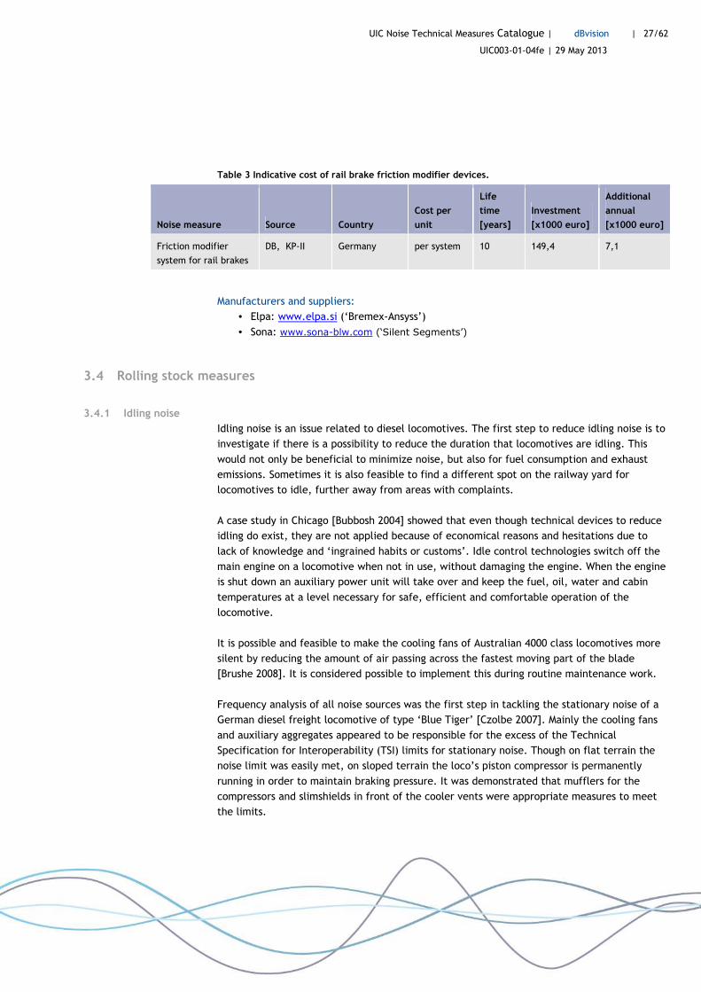
The indicative cost of rail brake friction modifier systems is given in Table 3.
UIC Noise Technical Measures Catalogue | dBvision | 27/62
UIC003-01-04fe | 29 May 2013
Table 3 Indicative cost of rail brake friction modifier devices.
Noise measure Source Country
Cost per
unit
Life
time
[years]
Investment
[x1000 euro]
Additional
annual
[x1000 euro]
Friction modifier
system for rail brakes
DB, KP-II Germany per system 10 149,4 7,1
Manufacturers and suppliers:
• Elpa: www.elpa.si (‘Bremex-Ansyss’)
• Sona: www.sona-blw.com (‘Silent Segments’)
3.4 Rolling stock measures
3.4.1 Idling noise
Idling noise is an issue related to diesel locomotives. The first step to reduce idling noise is to
investigate if there is a possibility to reduce the duration that locomotives are idling. This
would not only be beneficial to minimize noise, but also for fuel consumption and exhaust
emissions. Sometimes it is also feasible to find a different spot on the railway yard for
locomotives to idle, further away from areas with complaints.
A case study in Chicago [Bubbosh 2004] showed that even though technical devices to reduce
idling do exist, they are not applied because of economical reasons and hesitations due to
lack of knowledge and ‘ingrained habits or customs’. Idle control technologies switch off the
main engine on a locomotive when not in use, without damaging the engine. When the engine
is shut down an auxiliary power unit will take over and keep the fuel, oil, water and cabin
temperatures at a level necessary for safe, efficient and comfortable operation of the
locomotive.
It is possible and feasible to make the cooling fans of Australian 4000 class locomotives more
silent by reducing the amount of air passing across the fastest moving part of the blade
[Brushe 2008]. It is considered possible to implement this during routine maintenance work.
Frequency analysis of all noise sources was the first step in tackling the stationary noise of a
German diesel freight locomotive of type ‘Blue Tiger’ [Czolbe 2007]. Mainly the cooling fans
and auxiliary aggregates appeared to be responsible for the excess of the Technical
Specification for Interoperability (TSI) limits for stationary noise. Though on flat terrain the
noise limit was easily met, on sloped terrain the loco’s piston compressor is permanently
running in order to maintain braking pressure. It was demonstrated that mufflers for the
compressors and slimshields in front of the cooler vents were appropriate measures to meet
the limits.
UIC Noise Technical Measures Catalogue | dBvision | 28/62
UIC003-01-04fe | 29 May 2013
Appendix C of the TSI Noise 2011 gives measurement details for stationary noise. Point C4.2
gives the definition of the normal operating conditions and does not include intermittent or
impulsive sources. It is technically possible to keep idling noise (e.g. from cooling fans) at a
fairly low level. However, the current TSI Noise does not set limits for intermittent or
impulsive sources, some of which can be major contributors to idling noise. Unless additional
noise criteria are included in the procurement specification there is currently no incentive for
manufacturers to reduce these annoying types of noise. Noise levels may be up to 15 dB
above what is acceptable for the environment. At the time of writing, proposals to include
requirements for intermittent and impulsive noise were under discussion within the TSI
revision working group and may be adopted in 2014.
3.4.2 Impact noise from bumping and coupling vehicles
Freight vehicles being shunted cause impact noise from bumping buffers and from coupling
the draw gears. For mitigation of these impact noises, no feasible technical solutions on the
vehicles are available to date. So far, optimization of the vehicle speed, allowing the vehicle
to couple as smooth as possible, is probably the only option.
3.5 Operational measures
Various operational measures have been suggested to reduce noise or annoyance from
marshalling and stabling yards [Roovers 2004a and 2004b, Beuving 2007]. The SILENCE project
produced a list of operational measures, and besides this also suggestions to change the
behaviour of the yard’s operating staff [SILENCE-IP 2008]. However, the feasibility of these
proposals on real yards is less documented.
On stabling yards, where passenger trains are parked, washed, heated and so on, some
flexibility is possible in handling and timing of noisy processes. But most marshalling yards
have to cope with tight constraints regarding location and period of actions, which make it
virtually impossible to re-arrange or relocate processes in a way that less annoyance is caused
near the dwellings.
Banedanmark applies operational measures for stationary noise on marshalling yards9.
Reduction of noise is forced by operation regulations. The main noise issue relates to idling
noise of locos. The operators have the opportunity to connect the train to an eletrical power
system to keep the cooling system running without having the engine of the train running.
After 5 minutes the train must be shut down and then the electricity power comes instead
from the power stations.
3.6 References
[Beuving 2007] Annoyance of depot noise - Guidelines for best practice, Beuving, DeltaRail, 2007
9 Information from Lisette Mortenssen (Banedanmark), May 2013.
UIC Noise Technical Measures Catalogue | dBvision | 29/62
UIC003-01-04fe | 29 May 2013
[Brushe 2008] A method of noise reduction for the cooling fans used in locomotives, Brushe, Chemeca, 2008
[Bubbosh 2004] Chicago Locomotive Idle Reduction Project, Bubbosh, EPA, 2004 [Czolbe 2007] Noise reduction measures at freight train locomotives 'Blue Tiger',
Czolbe, IWRN2007, 2007 [DBNetze 2012] Innovative Maßnahmen zum Lärm- und Erschütterungsschutz am
Fahrweg, DBNetze, DB Netze, 2012 [Hlaváček 2010] Assessment of rail brakes “BREMEX-ANNSYS” at the yard Brno-
Maloměřice, Hlaváček, VUZ, 2010 [Hlaváček 2012] NOVIBRAIL - Hlukové emise a vibrace v systému železnice, Hlaváček,
VUZ, 2012 [IMAGINE 2006] Description of the Source Database, IMAGINE, IMA07TR-050418-DGMR02,
2006 [Roovers 2004a] Inno-Emplacement; Eindrapport Haalbaarheidstudie, Roovers, ProRail,
2004 [Roovers 2004b] Inno-Emplacement Innovatiefase Haalbaarheidsstudie, Roovers, Prorail,
2004 [Roovers 2008] Eindrapport Geluid op Emplacementen - bijdrage van het IPG (2002-
2007), Roovers, Prorail, 2008 [SILENCE-IP 2008] Railway and tram depots handbook, SILENCE-IP, SILENCE-IP, 2008 [Strobel 2009] Lärmmessungen Balkenbremsen Rangierbahnhof Basel SBB RB Ost,
Strobel, Planteam, 2009 [TNO 2008] TNO Andante - Locating and characterising multiple noise events, TNO,
flyer, 2008
UIC Noise Technical Measures Catalogue | dBvision | 30/62
UIC003-01-04fe | 29 May 2013
4 Noise from switches
Executive summary
Switches and crossings produce impact noises and various types of screeching noise. If the
wagon’s wheelset passes through the switch, it will encounter several interruptions that
produce impact noise. The noise of a whole train typically sounds like rattling. Jointless
switches are state-of-the-art in most railway networks (2-4 dB(A)). For existing switches most
of those interruptions can in principle be replaced by thermite weldings. Insulated joints
cannot be welded. Remedies available are low wear (low noise) alternatives that minimize
vibrational effects. Also a crossing nose (see Figure 6) or frog cannot be welded. Remedies
like swingnose crossings have no significant excess noise compared to normal tracks. In short
switches it is not possible to completely avoid impact noise.
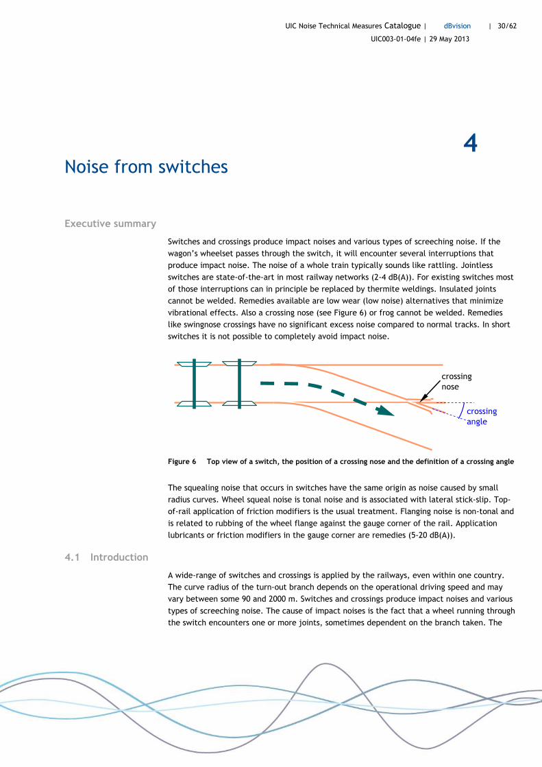
crossing nose
crossing angle
Figure 6 Top view of a switch, the position of a crossing nose and the definition of a crossing angle
The squealing noise that occurs in switches have the same origin as noise caused by small
radius curves. Wheel squeal noise is tonal noise and is associated with lateral stick-slip. Top-
of-rail application of friction modifiers is the usual treatment. Flanging noise is non-tonal and
is related to rubbing of the wheel flange against the gauge corner of the rail. Application
lubricants or friction modifiers in the gauge corner are remedies (5-20 dB(A)).
4.1 Introduction
A wide-range of switches and crossings is applied by the railways, even within one country.
The curve radius of the turn-out branch depends on the operational driving speed and may
vary between some 90 and 2000 m. Switches and crossings produce impact noises and various
types of screeching noise. The cause of impact noises is the fact that a wheel running through
the switch encounters one or more joints, sometimes dependent on the branch taken. The

UIC Noise Technical Measures Catalogue | dBvision | 31/62
UIC003-01-04fe | 29 May 2013
noise of a whole train typically sounds like rattling. Apart from a rattling sounds, also squeal
noise and flanging noise can be a nuisance. These noises are similar to those described in
Chapter 2 on curve squeal. A switch also often contains check rails to avoid derailment, which
may lead to additional flange-related noises.
A switch also produces noise when it is thrown. This noise level is generally much lower than
that of a train running through it, and is therefore not normally considered to be a problem
that needs to be solved.
Switches and crossings are sensitive parts of the railway system. Proper performance of these
units requires much attention and budget. Therefore switches often represents a significant
part of the overall track maintenance budget. Practical noise control measures will have to
be sensitive to this issue and avoid any significant increase to these already high costs. For
example:
- Sweden: 13% of the annual maintenance budget was spent by Banverket on their 12 000
switches and crossings in 2005.
- The Netherlands: The 7 500 switches and crossings consume 35% of ProRail’s maintenance
budget. The investment costs per unit are 250 000 euro and the same budget is spent on
maintenance during its average life time of 18 years [ProRail 2010b].
4.2 Technical description
Rattling noise due to joints
If the wheelset passes through the switch, it will encounter several interruptions that produce
impact noise. There are basically two kinds of interruptions:
• Rail joints. Jointed switches are usually found on parts of the network where the speed is
low (stations, yards and junctions).
• The gap near the crossing nose or frog. This gap is not present in so-called swingnose
crossings.
A wheel passing an interruption invokes high contact forces. A gap is described physically by
its width, the step height (vertical level difference on either side of the gap), and the dip
angle (caused by the rail edge being pushed down by the wheel) [Thompson 2009]. Advanced
model calculations show that the impact noise is mainly caused by the depth and the dip
angle, so the gap width is rather unimportant. The speed dependency of the impact sound
power of a single joint is about 20 log V. This means that the noise at 80 km/h is about 6
dB(A) higher than at 40 km/h.
The relative displacement that is caused in the wheel/rail system by a wheel passing a joint
can be described by an equivalent roughness spectrum. The theoretical basis for this
conversion is given by Wu and Thompson, see for example [Wu 2001].

UIC Noise Technical Measures Catalogue | dBvision | 32/62
UIC003-01-04fe | 29 May 2013
Most railways nowadays apply jointless switches and crossings on the network, especially
were speeds well above 40 km/h are to be achieved. The turnout length of those switches is
fairly large and the frog angle is shallow. If jointless switches and crossings are maintained
well, there is no reason that they should cause excess noise, compared to the rolling noise on
the track before and after them.
toe
switch rail stock rail
crossing
switch
stock rail
crossing nose or frog
check rail wing
rail wing rail
check rail
crossing
closure rail
Figure 7 Lay-out and terminology of switches and crossings.
Squealing noise due to curvature
The high pitch noises that occur in switches have the same origin as noise caused by small
radius curves. It is important to be able to distinguish between flanging noise and curve
squeal noise in a switch, as different solutions are proposed to either of them.
• Wheel squeal noise is tonal noise corresponding to distinct modal frequencies of the
wheel, as described in detail in Chapter 2. Squeal noise is associated with lateral stick-
slip. Top-of-rail application of friction modifiers is the usual treatment, see Chapter 2.
• More typical for switches than for curves are different noises related to rubbing of the
wheel flange against the gauge corner of the rail. Also the noise of the flange against the
check rail is noticeable. Flanging noise is non-tonal and sounds more or less like
consonants ‘f’ and ‘s’ (at high levels). Application lubricants or friction modifiers in the
gauge corner are remedies.

UIC Noise Technical Measures Catalogue | dBvision | 33/62
UIC003-01-04fe | 29 May 2013
Other noises related to flange rubbing have been described as low frequency ‘graunching’
[Thompson 2009].
Figure 8 Cross-section of wheel and rail.
4.3 Solutions
4.3.1 Jointless switches
Most of those interruptions in a switch and crossing can in principle be replaced by thermite
weldings, as is explained in a text frame in this section. The insulated joints that are needed
for signalling cannot be welded, but there are low wear (low noise) alternatives that
minimize the vibrational effects of those gaps.
Another interruption that cannot be welded is located at the crossing nose or frog
[Nieuwenhuizen 2011]. This means that a switch that is made jointless by welding
(retrofitting) will still keep one impact point. In switches with shallow crossing angles it is
possible to apply swingnose crossings (moveable frogs). Check rails are absent in such
crossings. Switch systems with swingnose crossings have no significant excess noise compared
to normal tracks [Oostermeijer 2002].
In short switches (high crossing angles), meant for low speeds (typically less than 40 km/h), it
is not possible to completely avoid impact noise.
A double slip switch10 contains two types of crossings: V-shaped and X-shaped. The impact
noise at the X-shaped crossing is usually much higher than at the V-shape, because both
wheels of a wheelset are forced to pass a gap there [Nieuwenhuizen 2011].
10 In many countries this is called an ‘English switch’
UIC Noise Technical Measures Catalogue | dBvision | 34/62
UIC003-01-04fe | 29 May 2013
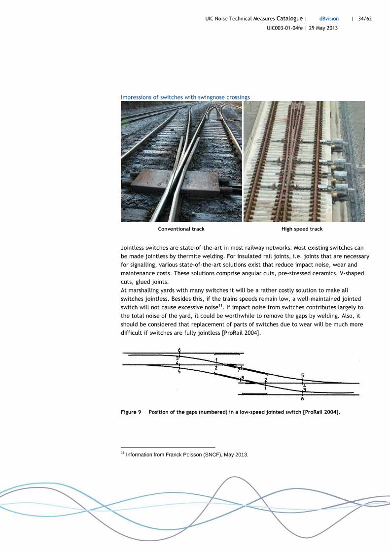
Impressions of switches with swingnose crossings
Conventional track High speed track
Jointless switches are state-of-the-art in most railway networks. Most existing switches can
be made jointless by thermite welding. For insulated rail joints, i.e. joints that are necessary
for signalling, various state-of-the-art solutions exist that reduce impact noise, wear and
maintenance costs. These solutions comprise angular cuts, pre-stressed ceramics, V-shaped
cuts, glued joints.
At marshalling yards with many switches it will be a rather costly solution to make all
switches jointless. Besides this, if the trains speeds remain low, a well-maintained jointed
switch will not cause excessive noise11. If impact noise from switches contributes largely to
the total noise of the yard, it could be worthwhile to remove the gaps by welding. Also, it
should be considered that replacement of parts of switches due to wear will be much more
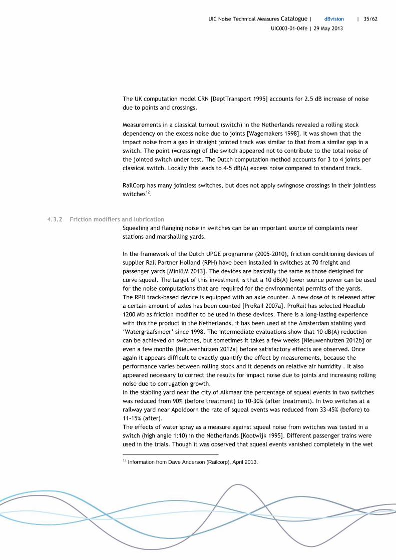
difficult if switches are fully jointless [ProRail 2004].
Figure 9 Position of the gaps (numbered) in a low-speed jointed switch [ProRail 2004].
11 Information from Franck Poisson (SNCF), May 2013.
UIC Noise Technical Measures Catalogue | dBvision | 35/62
UIC003-01-04fe | 29 May 2013
The UK computation model CRN [DeptTransport 1995] accounts for 2.5 dB increase of noise
due to points and crossings.
Measurements in a classical turnout (switch) in the Netherlands revealed a rolling stock
dependency on the excess noise due to joints [Wagemakers 1998]. It was shown that the
impact noise from a gap in straight jointed track was similar to that from a similar gap in a
switch. The point (=crossing) of the switch appeared not to contribute to the total noise of
the jointed switch under test. The Dutch computation method accounts for 3 to 4 joints per
classical switch. Locally this leads to 4-5 dB(A) excess noise compared to standard track.
RailCorp has many jointless switches, but does not apply swingnose crossings in their jointless
switches12.
4.3.2 Friction modifiers and lubrication
Squealing and flanging noise in switches can be an important source of complaints near
stations and marshalling yards.
In the framework of the Dutch UPGE programme (2005-2010), friction conditioning devices of
supplier Rail Partner Holland (RPH) have been installed in switches at 70 freight and
passenger yards [MinI&M 2013]. The devices are basically the same as those desigined for
curve squeal. The target of this investment is that a 10 dB(A) lower source power can be used
for the noise computations that are required for the environmental permits of the yards.
The RPH track-based device is equipped with an axle counter. A new dose of is released after
a certain amount of axles has been counted [ProRail 2007a]. ProRail has selected Headlub
1200 Mb as friction modifier to be used in these devices. There is a long-lasting experience
with this the product in the Netherlands, it has been used at the Amsterdam stabling yard
‘Watergraafsmeer’ since 1998. The intermediate evaluations show that 10 dB(A) reduction
can be achieved on switches, but sometimes it takes a few weeks [Nieuwenhuizen 2012b] or
even a few months [Nieuwenhuizen 2012a] before satisfactory effects are observed. Once
again it appears difficult to exactly quantify the effect by measurements, because the
performance varies between rolling stock and it depends on relative air humidity . It also
appeared necessary to correct the results for impact noise due to joints and increasing rolling
noise due to corrugation growth.
In the stabling yard near the city of Alkmaar the percentage of squeal events in two switches
was reduced from 90% (before treatment) to 10-30% (after treatment). In two switches at a
railway yard near Apeldoorn the rate of squeal events was reduced from 33-45% (before) to
11-15% (after).
The effects of water spray as a measure against squeal noise from switches was tested in a
switch (high angle 1:10) in the Netherlands [Kootwijk 1995]. Different passenger trains were
used in the trials. Though it was observed that squeal events vanished completely in the wet
12 Information from Dave Anderson (Railcorp), April 2013.

UIC Noise Technical Measures Catalogue | dBvision | 36/62
UIC003-01-04fe | 29 May 2013
switch, there was a slight increase in noise emission between 250 and 500 Hz. The
researchers found this rather 'rumbling' noise much less annoying than the squeal noise.
Cost
The indicative cost of friction modifier systems for switches is the same as for systems
applied in curves, see Table 1 on page 14.
4.4 References
[DeptTransport 1995] CRN - Calculation of Railway Noise, DeptTransport, HMSO, 1995 [Kootwijk 1995] Geluidsmetingen ter bepaling van het effect van een
watersproeiinstallatie op de geluidemissie bij door wisselbogen passerende treinen, Kootwijk, NSTO, 1995
[MinI&M 2013] Uitvoeringsprogramma Geluid Emplacementen (UPGE), MinI&M, Ministerie I en M, 2013
[Nieuwenhuizen 2011] Stootgeluid in voegloze wissels, Nieuwenhuizen, M+P, 2011 [Nieuwenhuizen 2012a] Aanvullende meetserie ter bepaling van het effect van SSCS'en op
emplacement Alkmaar, Nieuwenhuizen, M+P, 2012 [Nieuwenhuizen 2012b] Meetprogramma op emplacement Apeldoorn ter bepaling van het
effect van spoorstaafconditionering, Nieuwenhuizen, M+P, 2012 [Oostermeijer 2002] Workshop geluidarm spoor - Geluidarme wissels, Oostermeijer, HR, 2002 [ProRail 2004] Richtlijn voor het voegloos maken van sporen, wissels,
wisselverbindingen, kruiswissels, kruisingen en emplacementen, ProRail, ProRail, 2004
[ProRail 2007a] Doeltreffend wapen tegen treinwielgepiep, ProRail, ProRail, 2007 [ProRail 2010b] ProRail wil af van 3500 kwetsbare spoorwissels, ProRail, Volkskrant, 2010 [Thompson 2009] Railway Noise and Vibration-Mechanisms, Modelling and Means of
Control, Thompson, Elsevier (Oxford), 2009 [Wagemakers 1998] Rolgeluid op voegenspoor en de invloed van wegen, Wagemakers, NSTO,
1998 [Wu 2001] On the impact noise generation due to a wheel passing over rail joints,
Wu, ISVR, 2001

UIC Noise Technical Measures Catalogue | dBvision | 37/62
UIC003-01-04fe | 29 May 2013
5 Other noise measures
Executive summary
In this final chapter new techniques and developments of mitigation methods against rolling
noise are treated. Rolling noise is the most common source of railway noise, caused by wheel
and rail vibrations that are induced by the combined rail and wheel roughness in the contact
patch.
There is a long history of technical measures against rolling noise. Some solutions aim at
reducing rail roughness, for example by acoustic grinding (1-3 dB(A)), and wheel roughness,
by applying LL and K blocks instead of cast-iron braking blocks (8-10 dB(A)). Other methods
attempt to reduce the sound power at the source by vibration absorbers, such as rail dampers
(0-3 dB(A)) and wheel dampers (0-2 dB(A)). Finally, the transfer path from the track to the
environment can be shielded by noise barriers.
wheel roughness
rail roughness
rolling noise
Roughness excitation in the contact patch depending on train speed
Figure 10 Rolling noise generation.
5.1 Introduction
This chapter deals with technical solutions against other sources of railway noise. A division is
made between infrastructure-related and vehicle-related solutions.
The infrastructure measures are:
• Rail dampers
• Acoustic grinding
• Low height barriers close to the track
• Special barrier tops

UIC Noise Technical Measures Catalogue | dBvision | 38/62
UIC003-01-04fe | 29 May 2013
The rolling stock measures are:
• Wheel dampers
• K and LL blocks
5.2 Infrastructure measures
5.2.1 Rail dampers
Introduction
Rail dampers (or rail absorbers) are devices that reduce rolling noise by absorbing vibrations
of the rail. Rail dampers consist of elements that are mounted to the rail web and foot, and
sometimes also under the rail foot. Most types are placed at mid-span, halfway between the
sleepers or fasteners. The first practical applications of rail dampers were on railway bridges.
A large step forward was made with the Silent Track rail damper (2000). This type was
effective on normal tracks as well. Many more dampers have been designed and tested during
the past decade.
Technical description
The working principle of the rail damper is that the vibration bending waves in the rail, that
radiated the noise, are attenuated [Thompson 2009]. The performance of rail dampers is
characterised by the extend to which the track decay rate (TDR) is increased: the higher the
decay rate, the lower the noise emission of rail and sleeper. As the rail is already highly
damped, a good rail damper design will require a substantial amount of mass. The spring-
mass system of an effective damper is tuned in a wide range between 500 and 2000 Hz, where
the rail vibrations are important sources of rolling noise.
On theoretical grounds it can be expected that rail dampers also (slightly) reduce corrugation
growth [Thompson 2009]. Short-term field tests seem to confirm this [Ho 2012], but long-term
experiments would be necessary to prove this.
The effect of a rail damper cannot be expressed in a single noise reduction value that is valid
for every country or situation. This is because the noise reduction depends largely on the
characteristics of the track system without dampers. Figure 11 visualizes how rail dampers
reduce the track contribution and thereby the total rolling noise. On most track systems, the
sound power emitted by the vehicle is (much) less than that of the track. The rail damper
does not affect the vehicle contribution. If the track is the dominating source, the total noise
can be reduced considerably. At low speeds (<40 km/h), where traction noise may dominate
the total noise, rail dampers will be ineffective. At high speeds, where aerodynamic noise is
important, an effect of rail dampers of 1 dB(A) could still be determined. This is shown by
measurements in France at speeds around 300 km/h still show [Létourneaux 2007].

UIC Noise Technical Measures Catalogue | dBvision | 39/62
UIC003-01-04fe | 29 May 2013
Figure 11 Left: rolling noise on normal track. Right: rolling noise on track with rail dampers.
In order to assess the efficiency of dampers, the STARDAMP project (2010-2012) has
developed an ‘easy-to-handle methodology which allows manufacturers and end users to
predict the noise mitigation potential of a damper on the basis of readily available laboratory
tests without the necessity to perform field tests’ [Venghaus 2012]. This is possible because
the additional damping caused by rail dampers can be superposed to the existing damping of
a real track without dampers. The damping efficiency of the products can be estimated using
a free rail in a laboratory, supported by very soft rubber pads. The project has delivered a
software tool that enables users to calculate the noise reduction of different dampers on
different track systems.
Figure 12 Car Park Test with different rail dampers in Switzerland [Oertli 2013].
In Switzerland a large feasibility study including a field test programme with rail dampers is
being conducted by SBB during 2010-2013 [Oertli 2013]. This study pays attention to the
UIC Noise Technical Measures Catalogue | dBvision | 40/62
UIC003-01-04fe | 29 May 2013
effect of possible variations on the network (sleeper type, pad type, age, rolling stock,
speed, temperature) on the noise reduction by rail dampers. This is important because of
varying degrees of success with dampers in other countries. Variations of the achieved noise
reduction measured on similar sites were sometimes of the same order of magnitude as the
noise reduction itself. For this purpose the TDR has been measured on many representative
locations of the network. Meanwhile, the so-called Car Park Test set-up, developed in
STARDAMP, was followed (see Figure 12). The four rail dampers on trial were made by Tata,
Vossloh, S&V and STRAIL.
The results in terms of the predicted noise reduction on different Swiss track types are still
being studied and have not yet been published. So far, it can be concluded that the
differences in TDR between track types are much larger than the differences in damping
efficiency between different rail dampers.
In the framework of the German Konjukturprogramm II, five different types of rail dampers
were mounted on 92 km of track between 2009 and 2011 [DBNetze 2012]. The achieved noise
reduction depends on the type of product but also on the rolling stock. The best performing
dampers types appear to reduce the noise by 2 dB(A) on average (for speed < 200 km/h). In
the same test program also ‘rail screens’ were investigated. These mini-screens are attached
to the rail in a similar way as rail dampers, but they only absorb the noise radiated from the
rails and do not affect rail vibrations. Again, the noise reduction varies with rolling stock and
with the type of screening product. The average reduction of the total noise was 3 dB(A),
which is slightly higher than for the rail dampers.
According to the UIC questionnaire of 2012 about 140 km of track in Germany has been
equipped with rail dampers [DHV 2013b].
In France dampers were tested on tracks and on bridges [Scossa-Romano 2012]. The acoustic
performance of dampers was tested in 2004. Design requirements for the dampers included
that the operation and maintenance of the track will not be affected. The dampers were
installed on a conventional railway line with ballasted track, bibloc concrete sleepers, UIC60
rail, 9 mm stiff rubber rail pads. The rail dampers were the Corus Silent Track (now by Tata
Steel) and Schrey und Veit dampers. The noise reduction at operational train speeds was
between 1.7 and 2.9 dB(A). This performance was not sensitive to the type of rolling stock,
however, appeared to depend on the reference track definition. After repeated
measurements in 2005, the conclusive reported reduction on normal track was between 2 and
4 dB(A). On the Gavignot bridge a reduction of 4 to 5 dB(A) was measured.
According to the UIC questionnaire of 2012 about 50 km of track in France has been equipped
with rail dampers [DHV 2013b].
In Sweden and the Netherlands noise reductions between 1 and 3 dB(A) were measured with
various dampers [Verheijen 2003, Nielsen 2009a and 2009b]. In the Netherlands, finally only
the Schrey und Veit and Tata steel rail dampers were admitted to the network [ProRail
2007b]. For both a fixed 3 dB(A) reduction is accounted in the national computation method.

UIC Noise Technical Measures Catalogue | dBvision | 41/62
UIC003-01-04fe | 29 May 2013
ProRail calculated that rail dampers are more cost-effective on a double track than noise
barriers of 1 meter height at one side of the railway line . Because of this, between 2007 and
2012 about 106 km of rail dampers have been installed on the Dutch network at locations
where otherwise (higher) barriers would have been necessary.
In 2011 Banedanmark tested the effect of rail dampers . From these tests Banedanmark
decided not use rail dampers as a noise measure. The main reason was the relatively small
noise reduction in view of the increased complexity of the railway track system.
In the Czech Republic, the Vossloh and Tata Steel dampers have been used since 2008 and so
far been installed on three track sections . Especially with freight trains, the dampers seem
to perform less than with disc braked passenger trains. Besides this, noise measurements
after implementation demonstrated that the efficiency of the Vossloh damper decreased.
Dampers of various makes have been tested: Schrey und Veit, Tata Steel, Vossloh,
STRIALastic, CDM and others.
In the state-of-the-art UIC report Rail Dampers, Acoustic Rail Grinding, Low Height Noise
Barriers [Scossa-Romano 2012] it is concluded that there is a large variability in the results
ranging from small increases in noise to a maximum noise reduction of usually not more than
3 dB.
Impressions of rail dampers mounted in track
Vossloh ‘short without coupler’ Tata Steel ‘Silent Track’

UIC Noise Technical Measures Catalogue | dBvision | 42/62
UIC003-01-04fe | 29 May 2013
Schrey & Veit ‘AMSA60’ STRAIL ‘STRAILastic’
Wilson Acoustics ‘WAL rail damper’ CDM
Cost
The indicative cost of rail dampers is given in Table 4.

UIC Noise Technical Measures Catalogue | dBvision | 43/62
UIC003-01-04fe | 29 May 2013
Table 4 Indicative cost of rail dampers.
Noise measure Source Country Cost per unit
Life time [years]
Investment [x1000 euro]
Additional annual [x1000 euro]
DB, KP-II Germany per km track 13 226,2 10,7 Rail dampers
ProRail Netherlands per km track 25 240 11,9
Rail screens DB, KP-II Germany per km track 13 163,7 11,7
Manufacturers:
- CDM: www.cdm.eu
- Schrey & Veit: www.sundv.de
- STRAIL: www.strail.de
- Tata Steel: www.tatasteelrail.com
- Vossloh: www.vossloh-innotrans.com
- Wilson Acoustics: www.wal.hk
5.2.2 Maintenance grinding and acoustic grinding
Introduction
Rolling noise depends to a large extent on the sum of rail and wheel roughness. Therefore a
smooth rail is an important element in reducing railway noise [Scossa-Romano 2012]. Most
railways consider regular grinding to be an essential part of good track maintenance. Just like
ballast tamping, regular grinding can be cost-saving as track defects and safety issues
decrease.
Removal of the corrugation layer of the rail head can be achieved by different surface
treatment techniques, such as milling and grinding. Most railway infrastructure managers
apply a regular grinding regime for track maintenance. This will result in a railway network
without severe corrugation, with obvious acoustic benefits. For example, Network Rail
introduced a new grinding strategy from 2002, of which a large improvement of the overall
acoustic track quality by 8 dB(A) was suggested by a survey [Craven 2012].
Technical description
‘Acoustic grinding’ implies that an additional and dedicated grinding process aims at rolling
noise reduction. It means that the rails are kept in such (smooth) condition that in some
countries it is legally allowed to apply a lower than normal noise emission value in noise
computations (noise mapping or noise reception calculations of dwellings). However, as rail
roughness tends to grow back again after grinding, it will be necessary to monitor the noise
emission regularly, see Figure 13.

UIC Noise Technical Measures Catalogue | dBvision | 44/62
UIC003-01-04fe | 29 May 2013
time
noise level and roughness
acoustic grinding
regular grinding
regular grinding
noise reduction
average
average acoustic grinding
acoustic grinding
Figure 13 Effect of maintenance grinding and acoustic grinding as a function of time.
The first country that introduced acoustic grinding was Germany in the late 1990s
[Umweltbundesamt 1997] in the framework of a noise remedial program. The railway lines
that were treated by this new noise measure are called specially monitored tracks (German:
BüG). A fixed noise reduction of 3 dB(A) is associated with BüG in the German computation
model Schall 03. The roughness development is monitored regularly (twice a year) by a
special noise measuring train (Schallmesszug). If the emission limit is exceeded, the track is
ground again.
High Speed Grinding
High speed grinding has been developed in Germany as a special technical implementation of
maintenance grinding. While normal grinding trains run at low speed, the machines used for
high speed grinding (Vossloh Rail Services) can run up to 100 km/h (in Germany 80 km/h is
allowed). Because of this relatively high speed, less rail material can be removed per run, but
this may be compensated by running more often. The main advantage is that these high speed
grinding trains can operate without track closure. Because track occupancy time for
maintenance is reduced, the line capacity for normal service is increased.
It has furthermore been demonstrated in Konjunkturprogramm II that the resulting average
roughness of a track under the regime of high speed grinding is of the same quality as BüG
[DBNetze 2012]. A reduction of 6 dB(A) can be achieved. This means that high speed grinding
in principal could fulfill the requirements of acoustic grinding, though this has not yet been
acknowledged legally in Germany.
The indicative cost of high speed grinding is given in Table 4.

UIC Noise Technical Measures Catalogue | dBvision | 45/62
UIC003-01-04fe | 29 May 2013
Table 5 Indicative cost of high speed grinding13.
Noise measure Source Country
Cost per unit
Life time [years]
Investment [x1000 euro]
Additional annual [x1000 euro]
High speed (acoustic) grinding
DB Netz Germany per km track
- - 3.0 - 4.0
Roughness monitoring
The rail roughness and especially the effect of acoustic grinding should be monitored
regularly. For this purpose different methods have been developed or proposed. Most of these
apply a measuring coach, with microphones or axle-box accelerometers [Jones 2000,
Windelberg 2006, Bongini 2008, Delavaud 2009, Kuijpers 2009]. As the sensitivity of this
system is affected by the wheel roughness of the test vehicle, measuring bogie should
possibly have unbraked (i.e. smooth) wheels. Special algorithms are needed to process the
measured data into speed-independent values that can be compared with the legal limits. A
limitation of these monitoring devices is that besides rail roughness also differences in track
superstructure will determine the output [Bongini 2008].
Practical experience
In Finland acoustic grinding is tested as a measure on a track in 201114. The first tests showed
an increase of noise levels, while the second one shows a decrease. Grinding is not a regular
noise measure in Finland because there is no grinding train (different track gauge) and
because a lack of resources.
Banedanmark use high speed acoustic grinding at 80 km/h for sections with complaints about
noise15. In 2013 Banedanmark will finish a research project with acoustic grinding on 4 to 5
sites. At present, no results are available.
The Belgian infrastructure manager InfraBel has conducted a test programme during 2011-
2012 [Verhelst 2012]. During this programme a ‘semi-acoustic’ grinding treatment was
developed, featuring a final pass of the grinding train at 12 km/h instead of 5 km/h. The
target was to reduce the 2,5 cm corrugation waves better than with standard maintenance
grinding. This corrugation wavelength dominates the noise emission at 1 kHz at regular train
service speeds. By semi-acoustic grinding a 3-4 dB(A) noise reduction is achieved six months
after grinding.
13 Information from Bernhard Koch (DB Netz), May 2013. 14 Information from Erkki Poikolainen (Finnish Railways), February 2013. 15 Information from Lisette Mortensson (Banedanmark), February 2013.
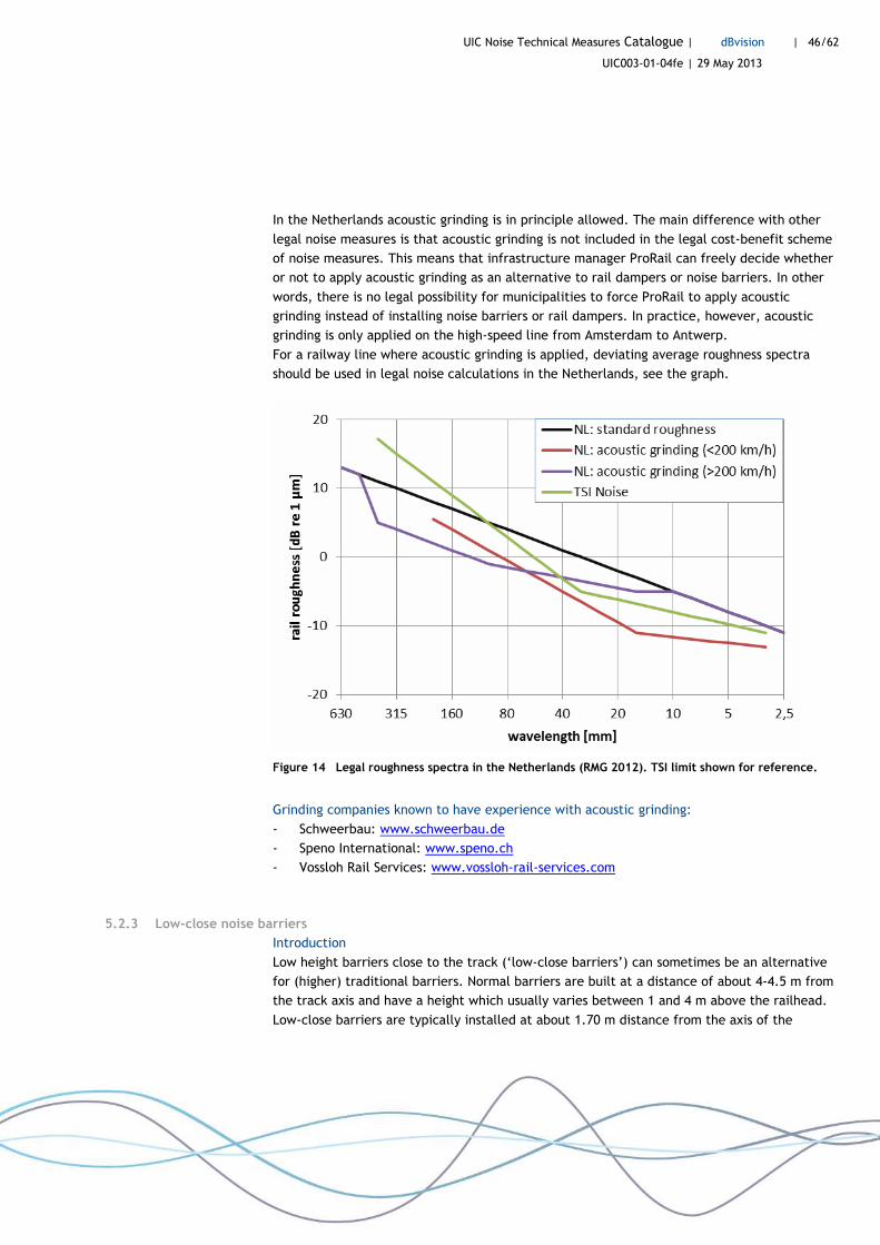
UIC Noise Technical Measures Catalogue | dBvision | 46/62
UIC003-01-04fe | 29 May 2013
In the Netherlands acoustic grinding is in principle allowed. The main difference with other
legal noise measures is that acoustic grinding is not included in the legal cost-benefit scheme
of noise measures. This means that infrastructure manager ProRail can freely decide whether
or not to apply acoustic grinding as an alternative to rail dampers or noise barriers. In other
words, there is no legal possibility for municipalities to force ProRail to apply acoustic
grinding instead of installing noise barriers or rail dampers. In practice, however, acoustic
grinding is only applied on the high-speed line from Amsterdam to Antwerp.
For a railway line where acoustic grinding is applied, deviating average roughness spectra
should be used in legal noise calculations in the Netherlands, see the graph.
Figure 14 Legal roughness spectra in the Netherlands (RMG 2012). TSI limit shown for reference.
Grinding companies known to have experience with acoustic grinding:
- Schweerbau: www.schweerbau.de
- Speno International: www.speno.ch
- Vossloh Rail Services: www.vossloh-rail-services.com
5.2.3 Low-close noise barriers
Introduction
Low height barriers close to the track (‘low-close barriers’) can sometimes be an alternative
for (higher) traditional barriers. Normal barriers are built at a distance of about 4-4.5 m from
the track axis and have a height which usually varies between 1 and 4 m above the railhead.
Low-close barriers are typically installed at about 1.70 m distance from the axis of the
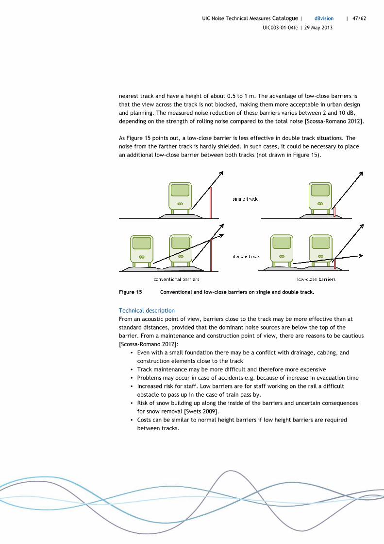
UIC Noise Technical Measures Catalogue | dBvision | 47/62
UIC003-01-04fe | 29 May 2013
nearest track and have a height of about 0.5 to 1 m. The advantage of low-close barriers is
that the view across the track is not blocked, making them more acceptable in urban design
and planning. The measured noise reduction of these barriers varies between 2 and 10 dB,
depending on the strength of rolling noise compared to the total noise [Scossa-Romano 2012].
As Figure 15 points out, a low-close barrier is less effective in double track situations. The
noise from the farther track is hardly shielded. In such cases, it could be necessary to place
an additional low-close barrier between both tracks (not drawn in Figure 15).
Figure 15 Conventional and low-close barriers on single and double track.
Technical description
From an acoustic point of view, barriers close to the track may be more effective than at
standard distances, provided that the dominant noise sources are below the top of the
barrier. From a maintenance and construction point of view, there are reasons to be cautious
[Scossa-Romano 2012]:
• Even with a small foundation there may be a conflict with drainage, cabling, and
construction elements close to the track
• Track maintenance may be more difficult and therefore more expensive
• Problems may occur in case of accidents e.g. because of increase in evacuation time
• Increased risk for staff. Low barriers are for staff working on the rail a difficult
obstacle to pass up in the case of train pass by.
• Risk of snow building up along the inside of the barriers and uncertain consequences
for snow removal [Swets 2009].
• Costs can be similar to normal height barriers if low height barriers are required
between tracks.
UIC Noise Technical Measures Catalogue | dBvision | 48/62
UIC003-01-04fe | 29 May 2013
Nevertheless, certain countries have attempted to make progress in admission of low-close
barriers to their railway network during the past decade. Their experiences are described
below.
Practical experience
The Zbloc barrier, tested in Sweden, is placed at 1.70 m from the centre of track, at 0.73
above the rail head [Nielsen 2009b]. The efficiency of the barrier varies from about 4-6 dB(A)
for freight trains, X40 train and IC train, until about 8-9 dB(A) for passenger trains X12 and
X60. The difference is caused by the lay-out of the X12 and X60 trains, causing the effective
source height of the train to be lower.
The National Rail Administration of Norway has approved the use of close-track barriers,
following an extensive assessment study for upgrading the Stavanger-Sandnes raillway line
[Swets 2009]. The residents along the line had strong objections against the 2-2.5 m height
barriers that were initially planned, because their sea views were blocked. Several
maintenance and safety issues had to be solved before the barriers were admitted. Pilot
projects in Sweden demonstrated that snow building up would not be a problem. A top
platform ensures that passengers could pass safely in case of emergency. Steps were fitted
every 30 m to allow safe descent.
The barrier design is 0.73 m above railhead, 1.70 m from track centre and the inner side is
with absorptive material. The acoustic efficiency of the barrier design is such that both tracks
need a barrier, were otherwise only one traditional barrier of 2-2.5 m height at normal
distance (4-4.5 m) would be sufficient. However, there appeared to be little difference in life
cycle costs compared to the traditional barrier.
Initially, ÖBB reported promising test results with low noise barriers near the track in Austria
in 2011 [Scossa-Romano 2012]. Due to safety issues, the product could not be admitted and
ÖBB decided not to proceed with low-close barriers16.
Low level noise barriers have been installed in the UK on the HSE1 (Channel Tunnel Rail Link)
on structures (bridges and viaducts). The original design consisted of traditional barriers of 2
m height at about 4-4.5 m from the centre of the track. The innovative design featured 1.4 m
high barriers placed at approximately 2.5 m from the centre of the track [NECR 2011].
ProRail is testing low-close barriers along 600 m of track in the town of Hilversum [Hilversum
2013]. The trial aims at gaining experience with maintenance and safety aspects.
Interestingly, an initial safety assessment led to the decision to place the 0.84 m high barriers
at 1.70 m (similar to platforms at stations) from the centre of track, while 2.35 m was
intended originally. The barrier design consists of stone-filled gabions tied together with
wire. The barrier has a step-shaped outer side for emergency situations.
16 Information from Günter Dinhobl (ÖBB), e-mail 11 April 2013.

UIC Noise Technical Measures Catalogue | dBvision | 49/62
UIC003-01-04fe | 29 May 2013
In Finland tests are planned with a barrier of height 0.85 m and length 2 x 140 m in
Tampere17.
In the German Konjunkturprogramm II (KP II) a test with 7 different low-close barriers at 9
locations was set up [DBNetze 2012]. Besides the earlier mentioned Zbloc barrier, also various
other types such as steel constructions and stone-filled gabions were investigated. The
barriers were placed at a distance of 1.75 m to the centre of the track, and had heights of
either 55 cm or 74 cm above the top of the rail. Acoustic measurements were conducted at 25
m distance at receiver heights 3.5 m, 6.3 m and 9.1 m. For the 74 cm barriers, the pass-by
noise of the track next to the barrier was reduced by about 6 dB(A), 5 dB(A) and 4 dB(A) for
the respective receiver heights. For the farther track, the reductions were lower: 4 dB(A), 1
dB(A) and 0 dB(A), respectively. The results for the 55 cm barriers varied between 0 at 3.5 m
receiver height and about 2 dB(A) at 3.5 m receiver height. The reduction effect for freight
trains was similar than for passenger trains, though sometimes 1 dB(A) less.
It was concluded for double-track situations with low-close barriers on both sides also a
middle barrier would be desirable, theoretically improving the total reduction by 2 dB(A).
However, this would probably require more space than usually available between existing
tracks. Currently for reasons of employment protection and evacuation, only the one-sided
barrier has been homologated.
Acoustic calculations
Besides technical and safety aspects, the introduction of barriers close to the track may
require that legal noise computation models have to be modified. Such models have been
designed to cope with regular distances of barriers and use simplifications that do not
necessarily hold for low barriers near the track. For example in the Netherlands the national
model has been tested for low-close barriers applications and was found to be suitable, but in
Germany these barriers would require model adaptations.
17 Information from Erkki Poikolainen (Finnish Railways), February 2013.

UIC Noise Technical Measures Catalogue | dBvision | 50/62
UIC003-01-04fe | 29 May 2013
Impressions of low-close barriers
KP II barrier Ludwigshafen KP II barrier Mannheim KP II barrier Oberwesel
KP II barrier Cologne Zbloc (Sweden) SoundIm Rail (Finland)
Installing 73 cm high barriers near Stavanger (Norway) with 30 cm wide top platform

UIC Noise Technical Measures Catalogue | dBvision | 51/62
UIC003-01-04fe | 29 May 2013
loading gauge
cess mini- barrier
Brenz SoundIm Rail (Finland) Stone-filled gabions (ProRail 2013)
Manufacturers: - Ferrondo barrier: www.ferrondo.de - ProKOP Rail: www.brens.cz - SoundIm barrier: www.soundim.fi - Zbloc barrier: zblocinternational.com
Cost
The indicative cost of low-close barriers is given in Table 6.
Table 6 Indicative cost of low-close barriers (74 cm height, rigid model, one-sided).
Noise measure Source Country
Cost per unit
Life time [years]
Investment [x1000 euro]
Additional annual [x1000 euro]
Low-close barriers
DB, KP-II Germany per km track
25 1152 0,0
5.2.4 Noise barrier tops
Introduction
Special barrier tops have been proposed to improve the performance of noise barriers. The
idea is that a noise barrier with such a top would be equally effective than a higher
traditional barrier. The designs range from a T-top concept to a cylindrical top, a mushroom-
shaped top edge, and an active noise control along the barrier’s top edge [Watson 2006].
Literature on these types of noise barriers concentrates mostly on road trffic applications.
Some countries conducted also tests along railway lines. Special top designs typically give a
reduction of a few decibels compared to a barrier without such a top. The observed effect

UIC Noise Technical Measures Catalogue | dBvision | 52/62
UIC003-01-04fe | 29 May 2013
depends strongly on the relative positions of the source, the barrier and the receiver. The
advantages of special barrier tops are:
• For new barriers: the total height can be lower, therefore the view from residents
across the railway line is blocked less.
• For existing barriers: a light-weight top construction does not require modification of
the foundation of the original barrier, and would therefore save costs in a situation
where the original barrier would have to be replaced by a slightly higher barrier.
Figure 16 Diffraction edge of a T-top (right) compared to a normal barrier (left).
Technical description
The acoustic principle of operation of T-top and similar tops is that the diffraction edge of
the barrier is moved closer to the source, thus slightly lifting the equivalent height of the
barrier (Figure 16). Certain other barrier top designs would improve the barrier’s diffraction
characteristics as a result of enlargement of the effective (absorptive) top surface but
sometimes also by Helmholtz resonators or other devices.
Tests in Austria with top elements for noise barriers demonstrated that effects were
noticeable but less effective than predicted18.
In The Netherlands a T-top noise barrier is developed for use along motorways. This
development was part of the Innovation Programme Noise [Ooststroom 2006]. Since 2006 this
barrier can be used as a regular noise measure. In The Netherlands no applications of barrier
tops along motorways or railway lines are known to date.
In Germany a comb-shaped diffraction top has been tested for railway applications [DBNetze
2012]. The top device was a construction with discs made of absorptive material. Comparison
with an equally high (2.5 m) conventional barrier showed no significant additional effect.
In France a modular top system has been developed and tested on a high speed line by SNCF
[Belingard 2010]. Several different configurations with absorptive top panels are possible.
These are placed in a metal frame on top of a concrete barrier. The Y-shaped configuration
18 Information from Günter Dinhobl (ÖBB), e-mail 11 April 2013.

UIC Noise Technical Measures Catalogue | dBvision | 53/62
UIC003-01-04fe | 29 May 2013
appeared to be most effective. This configuration consists of two absorptive upper branches
(V-shaped, height 1 meter) on top of a reflective basis of 1,1 m height (I-shaped) above the
railhead. Compared to a standard reflective barrier of 2.1 m height above the railhead, this
device yields an additional noise reduction of 4 dB(A) (TGV at 375 km/h, microphone at 25 m
from the track axis, 3.5 m above the railhead).
Impressions of special barriers tops
Regular noise barrier
Sound insulation > 20 dB(A)
Sound absorption > 9 dB(A) Cassette
2 m
Artist impression of a motorway T-top Detail of a motorway T-top (Netherlands)
Comb-shaped diffraction top (KP II) Modular top system, here with Y-shape (France)
No real life implementations with barrier tops along railways are known to date. Information
about manufacturers and suppliers of special barrier tops is not available.
UIC Noise Technical Measures Catalogue | dBvision | 54/62
UIC003-01-04fe | 29 May 2013
5.3 Rolling stock measures
5.3.1 Wheel dampers
Introduction
For a long time, application of wheel dampers has been more common in light-rail or
tramways than in heavy rail. But new rolling stock is increasingly equipped with wheel
dampers from the factory. An example is the Pendolino passenger trains in Finland19.
Technical description
There are various designs of wheel dampers:
• Plate dampers, a plate that absorbs noise and vibrations is mounted to the web
• Sandwich dampers, sets of sandwich dampers that are mounted to the tyre
• Ring dampers, a metal ring that is sprung into a groove in the tyre
• Constrained layer dampers, thin layers of damping material glued to the web
• Friction dampers, consisting of metal plates that produce friction energy while
damping vibrations
In practice the choice to implement a wheel damper on a certain wheel is limited. For
example, not all wheel dampers can be combined with cheek mounted disk brakes.
Practical experience
The noise reduction of DAAVAC multi-layered ring dampers on a TGV-duplex running at high
speed (250-300 km/h) was about 3 dB(A) [Létourneaux 2007]. An AGC train with DAAVAC
dampers at 80 km/h yielded about 1 dB(A) reduction [Asmussen 2008].
A freight wagon on which Lucchini wheel dampers were installed showed a noise reduction of
1 dB(A) at 80 km/h and 2 dB(A) at 120 km/h [Asmussen 2008].
In the LZarG project (2008-2012) the following wheel dampers were developed [Bänsch 2012]:
• Wheel damper (Schrey & Veit) for wheel set BA308 (Gutehoffnungshütte Radsatz)
• Wheel damper (Bochumer Verein Verkehrstechnik) for wheel set BA308 (Bochumer
Verein Verkehrstechnik)
In principle, a good wheel damper will not only reduce the wheel noise but also rail noise, but
this additional effect is usually negligible [Thompson 2009]. Measurements of the noise
reduction caused by a plate damper on the Airport Express train near Oslo gave 3 dB(A) effect
at 200 km/h [Färm 2001]. By model calculations it was estimated that this total effect was
composed of 5 dB(A) wheel noise reduction and 1 dB(A) rail noise reduction. At lower speeds,
the total noise reduction was lower, 1 dB(A).
19 Information from Erkki Poikolainen (Finnish Transport Agency - Liikennevirasto), February 2013.

UIC Noise Technical Measures Catalogue | dBvision | 55/62
UIC003-01-04fe | 29 May 2013
Impressions of dampers mounted to the wheel
Wheelset BA308 (GHH) + dampers (S&V) Wheelset BA309 (BVV) + dampers (BVV)
Freight wheel + Lucchini damper (SILENCE-IP) DAAVAC ring damper (by Valdunes+ENAC)
Cost
The indicative cost of wheel dampers is given in Table 7.
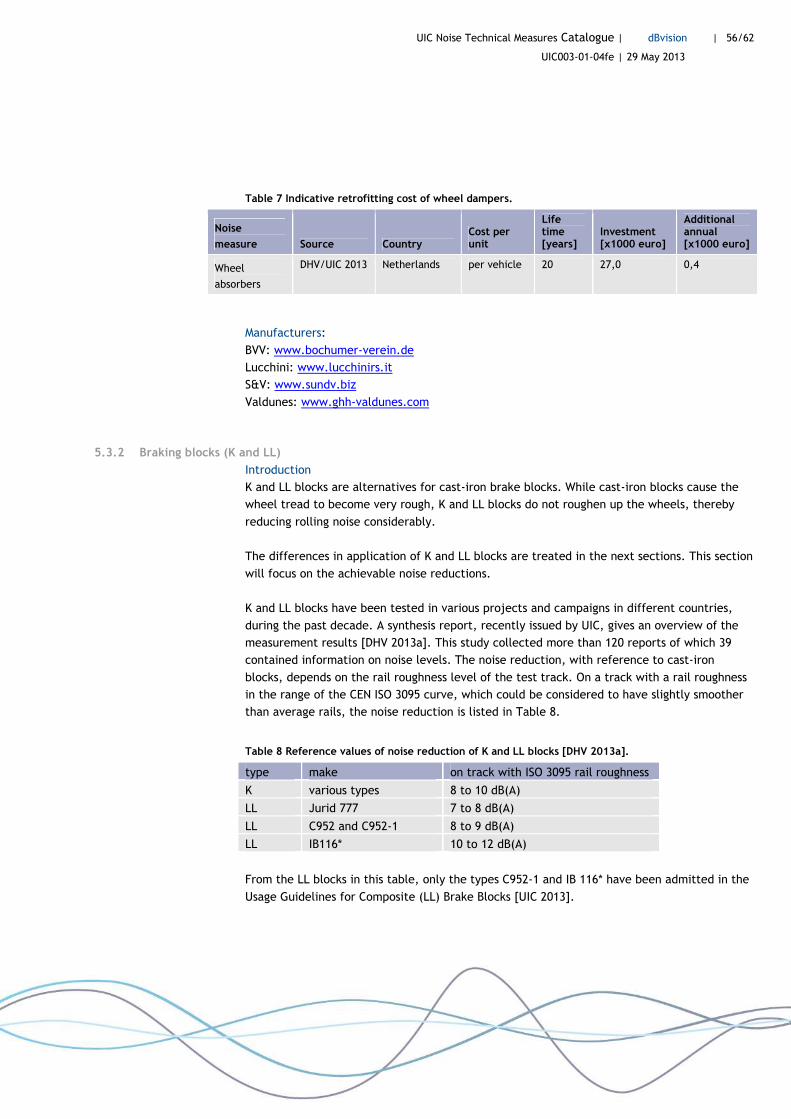
UIC Noise Technical Measures Catalogue | dBvision | 56/62
UIC003-01-04fe | 29 May 2013
Table 7 Indicative retrofitting cost of wheel dampers.
Noise
measure Source Country Cost per unit
Life time [years]
Investment [x1000 euro]
Additional annual [x1000 euro]
Wheel
absorbers
DHV/UIC 2013 Netherlands per vehicle 20 27,0 0,4
Manufacturers:
BVV: www.bochumer-verein.de
Lucchini: www.lucchinirs.it
S&V: www.sundv.biz
Valdunes: www.ghh-valdunes.com
5.3.2 Braking blocks (K and LL)
Introduction
K and LL blocks are alternatives for cast-iron brake blocks. While cast-iron blocks cause the
wheel tread to become very rough, K and LL blocks do not roughen up the wheels, thereby
reducing rolling noise considerably.
The differences in application of K and LL blocks are treated in the next sections. This section
will focus on the achievable noise reductions.
K and LL blocks have been tested in various projects and campaigns in different countries,
during the past decade. A synthesis report, recently issued by UIC, gives an overview of the
measurement results [DHV 2013a]. This study collected more than 120 reports of which 39
contained information on noise levels. The noise reduction, with reference to cast-iron
blocks, depends on the rail roughness level of the test track. On a track with a rail roughness
in the range of the CEN ISO 3095 curve, which could be considered to have slightly smoother
than average rails, the noise reduction is listed in Table 8.
Table 8 Reference values of noise reduction of K and LL blocks [DHV 2013a].
type make on track with ISO 3095 rail roughness
K various types 8 to 10 dB(A)
LL Jurid 777 7 to 8 dB(A)
LL C952 and C952-1 8 to 9 dB(A)
LL IB116* 10 to 12 dB(A)
From the LL blocks in this table, only the types C952-1 and IB 116* have been admitted in the
Usage Guidelines for Composite (LL) Brake Blocks [UIC 2013].
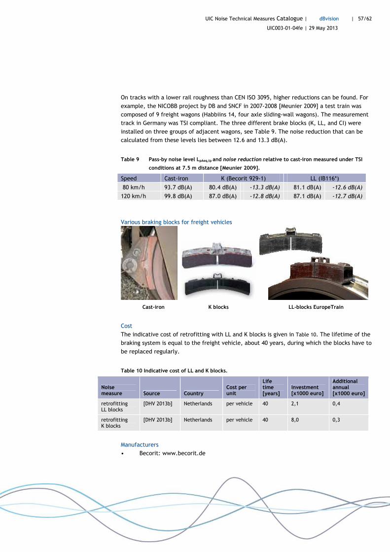
UIC Noise Technical Measures Catalogue | dBvision | 57/62
UIC003-01-04fe | 29 May 2013
On tracks with a lower rail roughness than CEN ISO 3095, higher reductions can be found. For
example, the NICOBB project by DB and SNCF in 2007-2008 [Meunier 2009] a test train was
composed of 9 freight wagons (Habbiins 14, four axle sliding-wall wagons). The measurement
track in Germany was TSI compliant. The three different brake blocks (K, LL, and CI) were
installed on three groups of adjacent wagons, see Table 9. The noise reduction that can be
calculated from these levels lies between 12.6 and 13.3 dB(A).
Table 9 Pass-by noise level LpAeq,tp and noise reduction relative to cast-iron measured under TSI
conditions at 7.5 m distance [Meunier 2009].
Speed Cast-iron K (Becorit 929-1) LL (IB116*)
80 km/h 93.7 dB(A) 80.4 dB(A) -13.3 dB(A) 81.1 dB(A) -12.6 dB(A)
120 km/h 99.8 dB(A) 87.0 dB(A) -12.8 dB(A) 87.1 dB(A) -12.7 dB(A)
Various braking blocks for freight vehicles
Cast-iron K blocks LL-blocks EuropeTrain
Cost
The indicative cost of retrofitting with LL and K blocks is given in Table 10. The lifetime of the
braking system is equal to the freight vehicle, about 40 years, during which the blocks have to
be replaced regularly.
Table 10 Indicative cost of LL and K blocks.
Noise measure Source Country
Cost per unit
Life time [years]
Investment [x1000 euro]
Additional annual [x1000 euro]
retrofitting LL blocks
[DHV 2013b] Netherlands per vehicle 40 2,1 0,4
retrofitting K blocks
[DHV 2013b] Netherlands per vehicle 40 8,0 0,3
Manufacturers
• Becorit: www.becorit.de
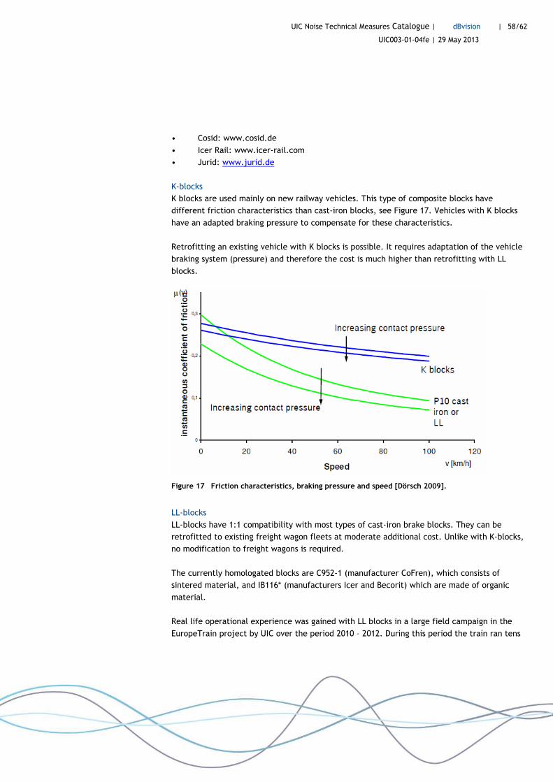
UIC Noise Technical Measures Catalogue | dBvision | 58/62
UIC003-01-04fe | 29 May 2013
• Cosid: www.cosid.de
• Icer Rail: www.icer-rail.com
• Jurid: www.jurid.de
K-blocks
K blocks are used mainly on new railway vehicles. This type of composite blocks have
different friction characteristics than cast-iron blocks, see Figure 17. Vehicles with K blocks
have an adapted braking pressure to compensate for these characteristics.
Retrofitting an existing vehicle with K blocks is possible. It requires adaptation of the vehicle
braking system (pressure) and therefore the cost is much higher than retrofitting with LL
blocks.
Figure 17 Friction characteristics, braking pressure and speed [Dörsch 2009].
LL-blocks
LL-blocks have 1:1 compatibility with most types of cast-iron brake blocks. They can be
retrofitted to existing freight wagon fleets at moderate additional cost. Unlike with K-blocks,
no modification to freight wagons is required.
The currently homologated blocks are C952-1 (manufacturer CoFren), which consists of
sintered material, and IB116* (manufacturers Icer and Becorit) which are made of organic
material.
Real life operational experience was gained with LL blocks in a large field campaign in the
EuropeTrain project by UIC over the period 2010 – 2012. During this period the train ran tens

UIC Noise Technical Measures Catalogue | dBvision | 59/62
UIC003-01-04fe | 29 May 2013
of thousands of kilometres. The above mentioned LL block types were fitted to Habbiillns and
RS. The vehicles with cast-iron were of the types Eas, Eanos, Shimmns, RS, Remms and
Sggmrs.
LL blocks require extra regular inspections to monitor wheel wear. The Usage Guidelines for
Composite (LL) Brake Blocks gives practical recommendations on the usage of the blocks [UIC
2013].
The wheel roughness as measured on wagons with LL blocks remains low, even after many
thousands of kilometers. Figure 18 shows measured wheel roughness spectra from the
EuropeTrain project. The differences in wheel roughness between wheels equipped with
different LL and K blocks is not significant. Variances of this order of magnitude are also
found between wagons with the same blocks.
Impressions of the wheel tread roughness resulting from different brake blocks
Cast-iron blocks LL-block IB116* LL-block C952-1

UIC Noise Technical Measures Catalogue | dBvision | 60/62
UIC003-01-04fe | 29 May 2013
Figure 18 Wheel roughness EuropeTrain [Heckelmüller 2012]. K-block from Nicobb project shown
for reference [Meunier 2009].
5.4 References
[Asmussen 2008] Field test in SILENCE, Asmussen, DB, 2008 [Bänsch 2012] Abschlussbericht zum Verbundproject L zar G - Leise Zug auf realm Gleis,
Bänsch, L Zar G, 2012 [Belingard 2010] Experimental study of noise barriers for high-speed trains, Belingard,
IWRN2010, 2010 [Bongini 2010] Noise mapping of a railway network: validation and use of a system
based on measurement of axlebox vibration, Bongini, SNCF, Innovation and Research Department, 2010
[Craven 2012] Responding to the Environmental Noise Directive by demonstrating the benefits of rail grinding on the GB railway network, Craven, RRUKA, 2012
[DBNetze 2012] Innovative Maßnahmen zum Lärm- und Erschütterungsschutz am Fahrweg, DBNetze, DB Netze, 2012
[Delavaud 2009] Time domain modelling of rolling noise - a new method of roughness data processing, Delavaud, EURONOISE2009, 2009
[DHV 2013a] Real noise reduction of freight wagon retrofitting, DHV, commissioned by UIC, 2013
[DHV 2013b] The real cost of railway noise mitigation - A risk assessment, DHV, commissioned by UIC, 2013
[Dörsch 2009] Technology of Composite Brake Blocks, Dörsch, DB, 2009 [Färm 2001] Evaluation of wheel dampers on an intercity train, Färm, IWRN2001,
2001

UIC Noise Technical Measures Catalogue | dBvision | 61/62
UIC003-01-04fe | 29 May 2013
[Heckelmüller 2012] Acoustic pass-by measurements for the EuropeTrain near Großburgwedel, Heckelmüller, DB, 2012
[Hilversum 2013] Stand van zaken geluidssanering, Hilversum, Council, 2013 [Ho 2012] Reduction of Corrugation Growth Rate by Rail Dampers, Ho, TDHRail,
2012 [Jones 2000] Remote monitoring systems for rail corrugation and curve squeal, Jones,
Railtex2000, 2000 [Kuijpers 2009] How to avoid the noise ceiling - Accommodating traffic growth by
smooth and silent track, Kuijpers, EURONOISE2009, 2009 [Létourneaux 2007] High Speed Railway Noise - Assement of Mitigation Measures,
Létourneaux, IWRN2007, 2007 [Meunier 2009] The UIC-project Noise Impact of Composite Brake Blocks (Nicobb),
Meunier, Deutsche Bahn AG, 2009 [NECR 2011] A strategic analysis of the sustainability case for High Speed 2 , NECR,
Natural England, 2011 [Nielsen 2009a] Reduction of railway rolling noise by use of rail dampers – results from a
field test in Tjörnarp, Nielsen, Chalmers University of Technology, 2009 [Nielsen 2009b] Quiet City Transport; Design & implementation of solutions at validation
sites, Nielsen, Acoustic Control, 2009 [Nielsen 2009b] Quiet City Transport; Design & implementation of solutions at validation
sites, Nielsen, Acoustic Control, 2009 [Oertli 2013] Erprobung Schienedämpfer Erste Resultate und weiteres Vorgehen,
Oertli, SBB, 2013 [ProRail 2007b] Tweede raildemper vrijgegeven, ProRail, ProRail, 2007 [Scossa-Romano 2012] Rail Dampers, Acoustic Rail Grinding, Low Height Noise Barriers; A
report on the state of the art, Scossa-Romano, SBB, 2012 [Swets 2009] On the extensive use of close-track noise barriers in a Norwegian railroad
project, Swets, EURONOISE2009, 2009 [Thompson 2009] Railway Noise and Vibration-Mechanisms, Modelling and Means of
Control, Thompson, Elsevier (Oxford), 2009 [UIC 2013] Usage guidelines for composite (LL) brake blocks, UIC, UIC, 2013 [Umweltbundesamt 1997] Amtliche Auskunft zum Gleispflegeabschlag für das
besonders überwachte Gleis, Umweltbundesamt, Berlin, 1997 [Venghaus 2012] Assessment of the efficiency of rail dampers using laboratory methods
within the STARDAMP project, Venghaus, DAGA2012, 2012 [Verheijen 2003] Modellering effect raildempers en specificatie afstandsdemping,
Verheijen, AEAT, 2003 [Verhelst 2012] Presentation Noise mitigation at Infrabel, Verhelst, Infrabel, 2012 [Watson 2006] Evaluation of benefits and opportunities for innovative noise barrier
designs, Watson, ADoT, 2006 [Windelberg 2006] Bewertung des akustischen Schienenzustandes durch den
Schallmesswagen, Windelberg, Immissionsschutz2006, 2006 [Ooststroom 2006] Toepassingsadvies: T-toppen, Van Ooststroom, Rijkswaterstaat, 2006

UIC Noise Technical Measures Catalogue | dBvision | 62/62
UIC003-01-04fe | 29 May 2013
Colophon
Title short
UIC Noise Technical Measures Catalogue
Client
International Union of Railways (UIC) Contract number: P350/12.319 Coordinator and contact person: Nick Craven Core group: Jakob Oertli (SBB), Martina Fleckenstein (DB), Ferat Göçmen (DB), Franck Poisson (SNCF), Jan Hlaváček (VUZ) and Peter Hübner (UIC). Contractor
dBvision Groenmarktstraat 39 NL-3521 AV Utrecht Tel: +31 30 2970391 E-mail: [email protected] Website: www.dBvision.nl Date
29 May 2013
Report reference
UIC003-01-04fe
Status
Final 1.0
Research by
Frank Elbers Edwin Verheijen Autorisation
Edwin Verheijen Author
Frank Elbers Approval