rapid led aurora led array kit - home | menari lighting led array.pdfrapid led aurora led array kit...
TRANSCRIPT

1
Rapid LED Aurora LED Array Kit
Contents Overview ....................................................................................................................................................... 1
Aurora LED Array Specifications ................................................................................................................... 2
Parts .............................................................................................................................................................. 2
Attaching Aurora LED Array to Lens .............................................................................................................. 3
Wiring Single Aurora Puck (Skip if wiring a Dual Aurora Puck Kit) ................................................................ 5
Wiring Double Aurora LED Arrays (See previous section if you have a single kit) ........................................ 7
Attaching Aurora LED Array to Heatsink ..................................................................................................... 10
Wiring the Aurora LED Array to Drivers ...................................................................................................... 12
Mean Well LPC and ELN Drivers (Skip if you have any other driver): ..................................................... 13
Wiring the Driver to AC Power ............................................................................................................ 13
Adjusting ELN Driver Current – Do this before applying any power ................................................... 15
RapidLED Nano Drivers with Potentiometer (Skip if you have any other driver): .................................. 17
Mean Well LDD-H Drivers (Skip if you have any other driver): ............................................................... 18
Wiring Power Cord to Power Supply................................................................................................... 18
LDD H-4 Board Layout ......................................................................................................................... 20
Installing the LDD-H Driver.................................................................................................................. 20
Connecting the Aurora Array to the Board ......................................................................................... 21
Finishing Up ................................................................................................................................................. 22
Overview As with any type of lighting retrofit, there are many dangers, difficulties, and pitfalls that may occur. The Aurora LED Array kits should be attempted by people familiar with electronics, LEDs, LED Drivers, and series circuits. If you are uncomfortable with or inexperienced at any of the prerequisites required for this kit, you should not attempt this retrofit. Please note for this document and on our site the terms “array” and “puck” are used interchangeably.
2
Aurora LED Array Specifications
• Each Array has 4 channels: o Blue - 4 XT-E Royal Blue + 3 XP-E Blue o Color - 2 XP-E Green + 1 XP-E Blue + 2 XP-E Red + 1 XP-E Red-Orange o White - 4 XP-G Cool White o UV - 4 SemiLEDs Violet UV
• The Current Rating for each channel is: o Blue - 1000mA Maximum (Recommended: 700mA to 850mA) o Color - 700mA Maximum (Recommended: 700mA) o White - 1500mA Maximum (Recommended: 700mA to 1100mA) o UV - 700mA Maximum (Recommended: 700mA)
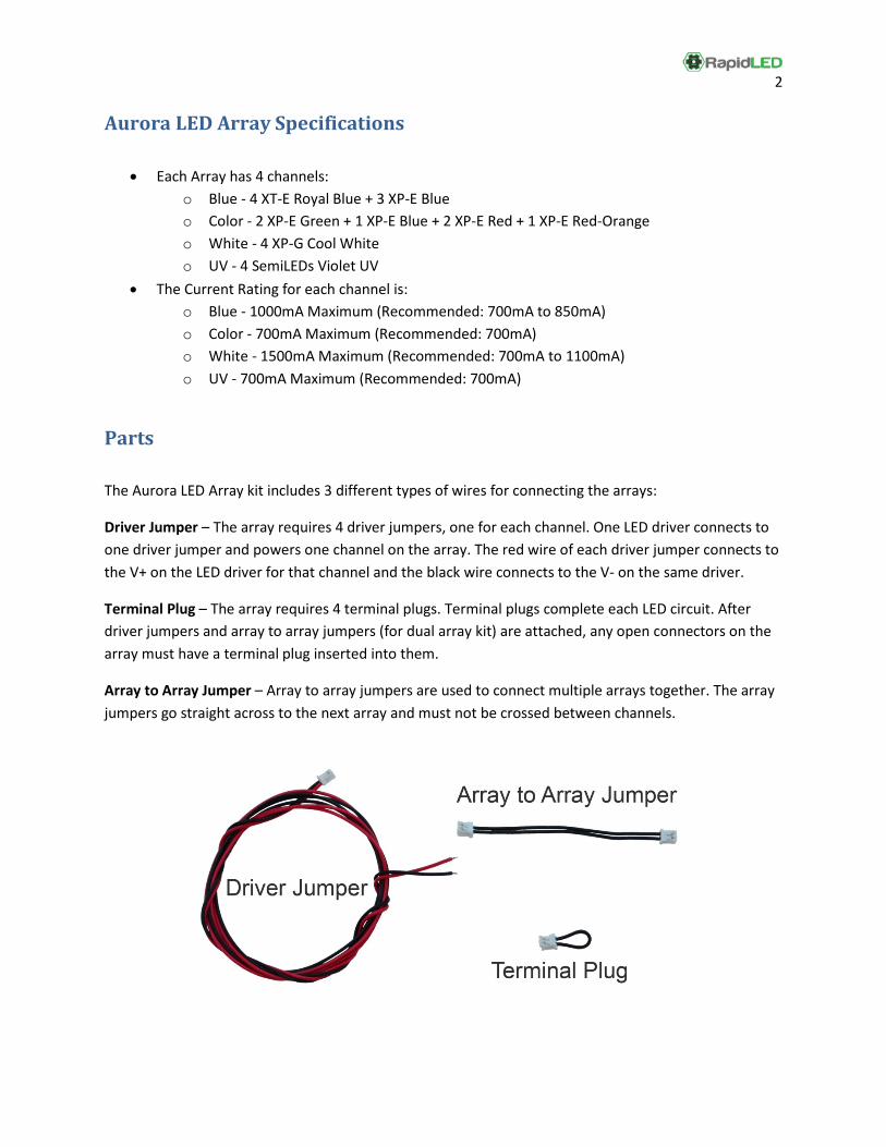
Parts The Aurora LED Array kit includes 3 different types of wires for connecting the arrays:
Driver Jumper – The array requires 4 driver jumpers, one for each channel. One LED driver connects to one driver jumper and powers one channel on the array. The red wire of each driver jumper connects to the V+ on the LED driver for that channel and the black wire connects to the V- on the same driver.
Terminal Plug – The array requires 4 terminal plugs. Terminal plugs complete each LED circuit. After driver jumpers and array to array jumpers (for dual array kit) are attached, any open connectors on the array must have a terminal plug inserted into them.
Array to Array Jumper – Array to array jumpers are used to connect multiple arrays together. The array jumpers go straight across to the next array and must not be crossed between channels.
3
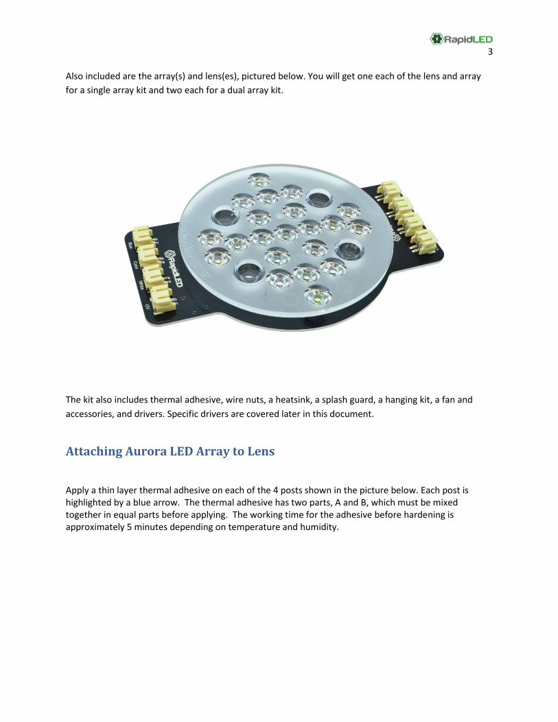
Also included are the array(s) and lens(es), pictured below. You will get one each of the lens and array for a single array kit and two each for a dual array kit.
The kit also includes thermal adhesive, wire nuts, a heatsink, a splash guard, a hanging kit, a fan and accessories, and drivers. Specific drivers are covered later in this document.
Attaching Aurora LED Array to Lens
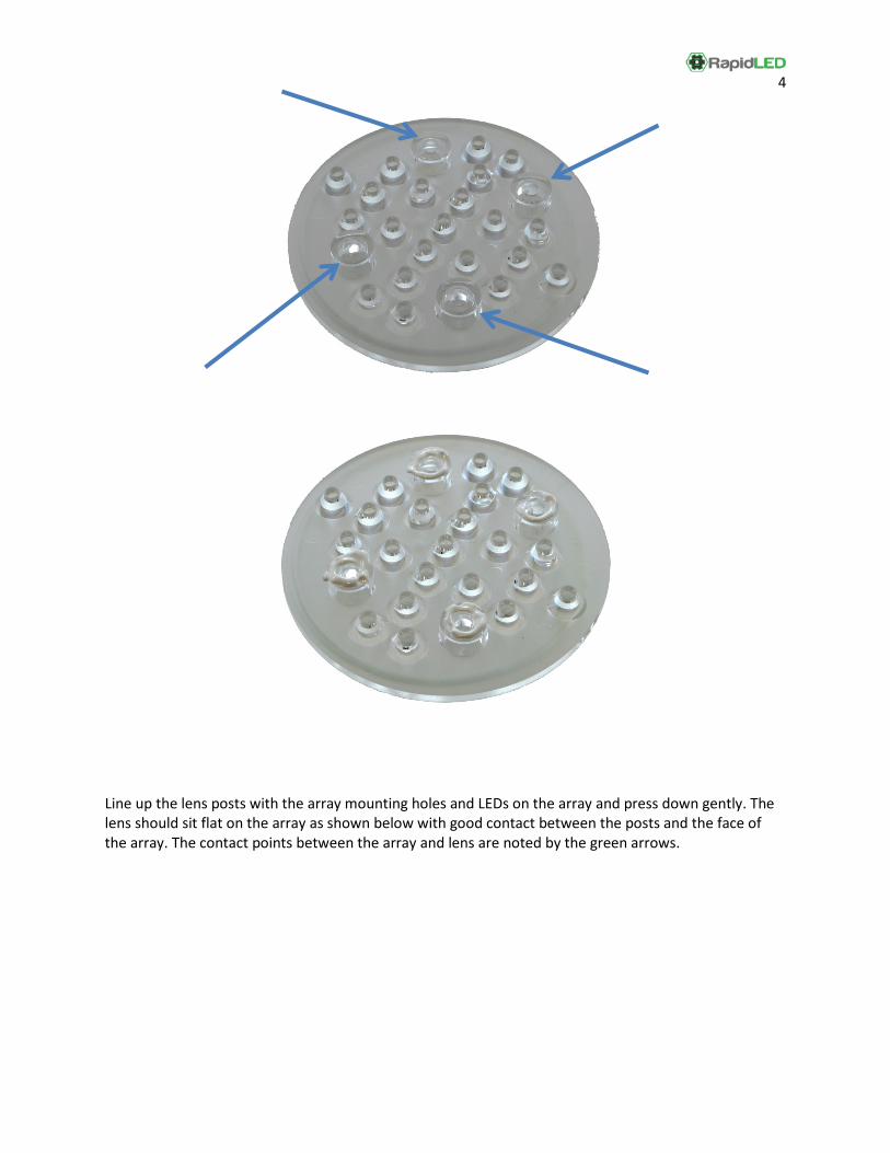
Apply a thin layer thermal adhesive on each of the 4 posts shown in the picture below. Each post is highlighted by a blue arrow. The thermal adhesive has two parts, A and B, which must be mixed together in equal parts before applying. The working time for the adhesive before hardening is approximately 5 minutes depending on temperature and humidity.
4
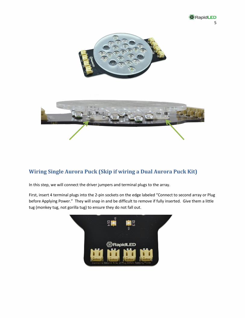
Line up the lens posts with the array mounting holes and LEDs on the array and press down gently. The lens should sit flat on the array as shown below with good contact between the posts and the face of the array. The contact points between the array and lens are noted by the green arrows.
5
Wiring Single Aurora Puck (Skip if wiring a Dual Aurora Puck Kit) In this step, we will connect the driver jumpers and terminal plugs to the array.
First, insert 4 terminal plugs into the 2-pin sockets on the edge labeled “Connect to second array or Plug before Applying Power.” They will snap in and be difficult to remove if fully inserted. Give them a little tug (monkey tug, not gorilla tug) to ensure they do not fall out.
6
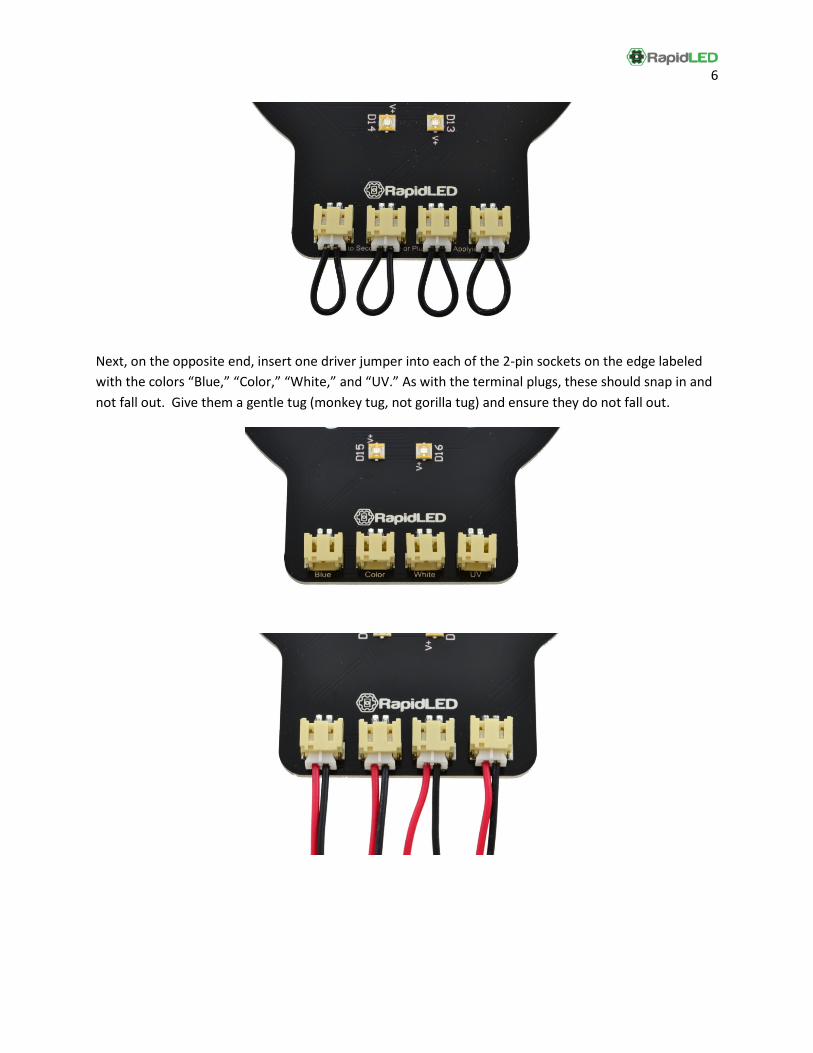
Next, on the opposite end, insert one driver jumper into each of the 2-pin sockets on the edge labeled with the colors “Blue,” “Color,” “White,” and “UV.” As with the terminal plugs, these should snap in and not fall out. Give them a gentle tug (monkey tug, not gorilla tug) and ensure they do not fall out.
7
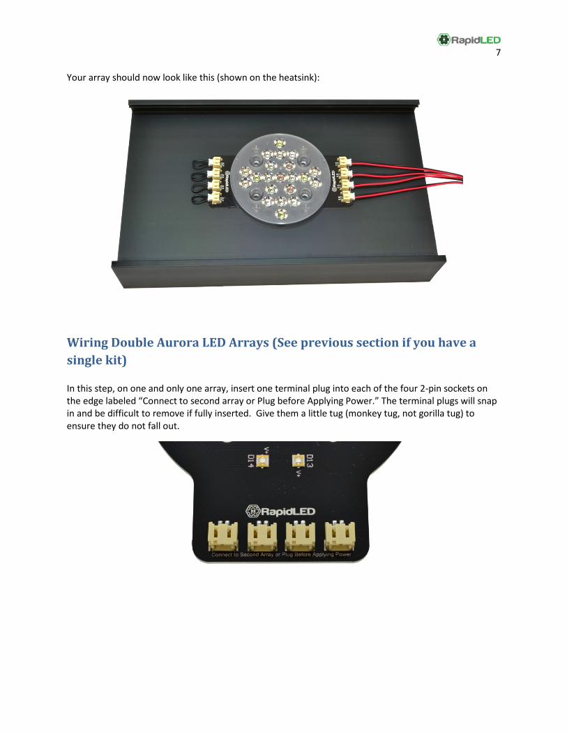
Your array should now look like this (shown on the heatsink):
Wiring Double Aurora LED Arrays (See previous section if you have a single kit) In this step, on one and only one array, insert one terminal plug into each of the four 2-pin sockets on the edge labeled “Connect to second array or Plug before Applying Power.” The terminal plugs will snap in and be difficult to remove if fully inserted. Give them a little tug (monkey tug, not gorilla tug) to ensure they do not fall out.
8
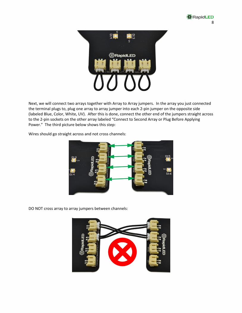
Next, we will connect two arrays together with Array to Array jumpers. In the array you just connected the terminal plugs to, plug one array to array jumper into each 2-pin jumper on the opposite side (labeled Blue, Color, White, UV). After this is done, connect the other end of the jumpers straight across to the 2-pin sockets on the other array labeled “Connect to Second Array or Plug Before Applying Power.” The third picture below shows this step:
Wires should go straight across and not cross channels:
DO NOT cross array to array jumpers between channels:
9
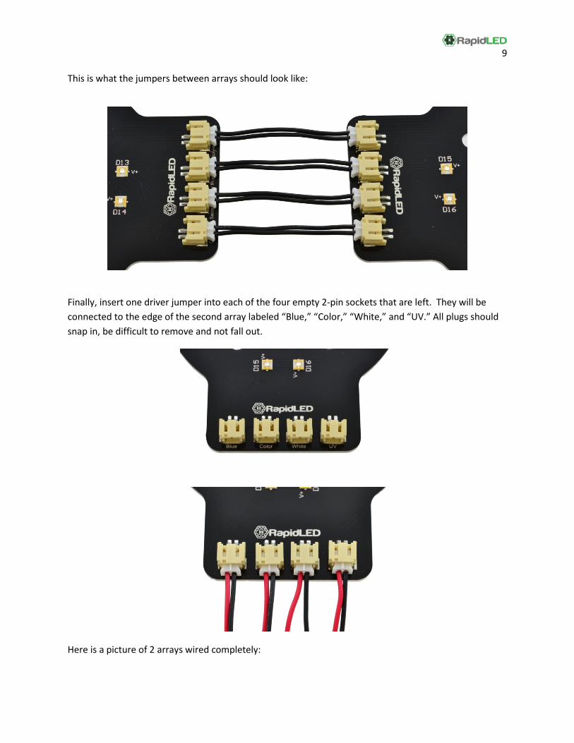
This is what the jumpers between arrays should look like:
Finally, insert one driver jumper into each of the four empty 2-pin sockets that are left. They will be connected to the edge of the second array labeled “Blue,” “Color,” “White,” and “UV.” All plugs should snap in, be difficult to remove and not fall out.
Here is a picture of 2 arrays wired completely:
10
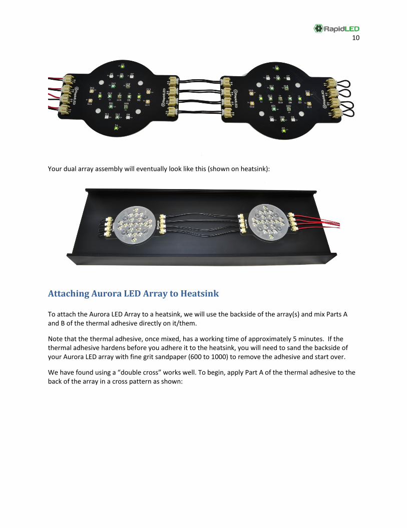
Your dual array assembly will eventually look like this (shown on heatsink):
Attaching Aurora LED Array to Heatsink To attach the Aurora LED Array to a heatsink, we will use the backside of the array(s) and mix Parts A and B of the thermal adhesive directly on it/them.
Note that the thermal adhesive, once mixed, has a working time of approximately 5 minutes. If the thermal adhesive hardens before you adhere it to the heatsink, you will need to sand the backside of your Aurora LED array with fine grit sandpaper (600 to 1000) to remove the adhesive and start over.
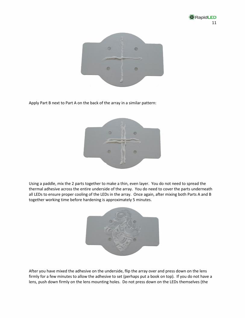
We have found using a “double cross” works well. To begin, apply Part A of the thermal adhesive to the back of the array in a cross pattern as shown:
11
Apply Part B next to Part A on the back of the array in a similar pattern:
Using a paddle, mix the 2 parts together to make a thin, even layer. You do not need to spread the thermal adhesive across the entire underside of the array. You do need to cover the parts underneath all LEDs to ensure proper cooling of the LEDs in the array. Once again, after mixing both Parts A and B together working time before hardening is approximately 5 minutes.
After you have mixed the adhesive on the underside, flip the array over and press down on the lens firmly for a few minutes to allow the adhesive to set (perhaps put a book on top). If you do not have a lens, push down firmly on the lens mounting holes. Do not press down on the LEDs themselves (the
12
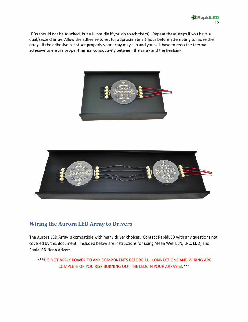
LEDs should not be touched, but will not die if you do touch them). Repeat these steps if you have a dual/second array. Allow the adhesive to set for approximately 1 hour before attempting to move the array. If the adhesive is not set properly your array may slip and you will have to redo the thermal adhesive to ensure proper thermal conductivity between the array and the heatsink.
Wiring the Aurora LED Array to Drivers The Aurora LED Array is compatible with many driver choices. Contact RapidLED with any questions not covered by this document. Included below are instructions for using Mean Well ELN, LPC, LDD, and RapidLED Nano drivers.
***DO NOT APPLY POWER TO ANY COMPONENTS BEFORE ALL CONNECTIONS AND WIRING ARE COMPLETE OR YOU RISK BURNING OUT THE LEDs IN YOUR ARRAY(S).***
13
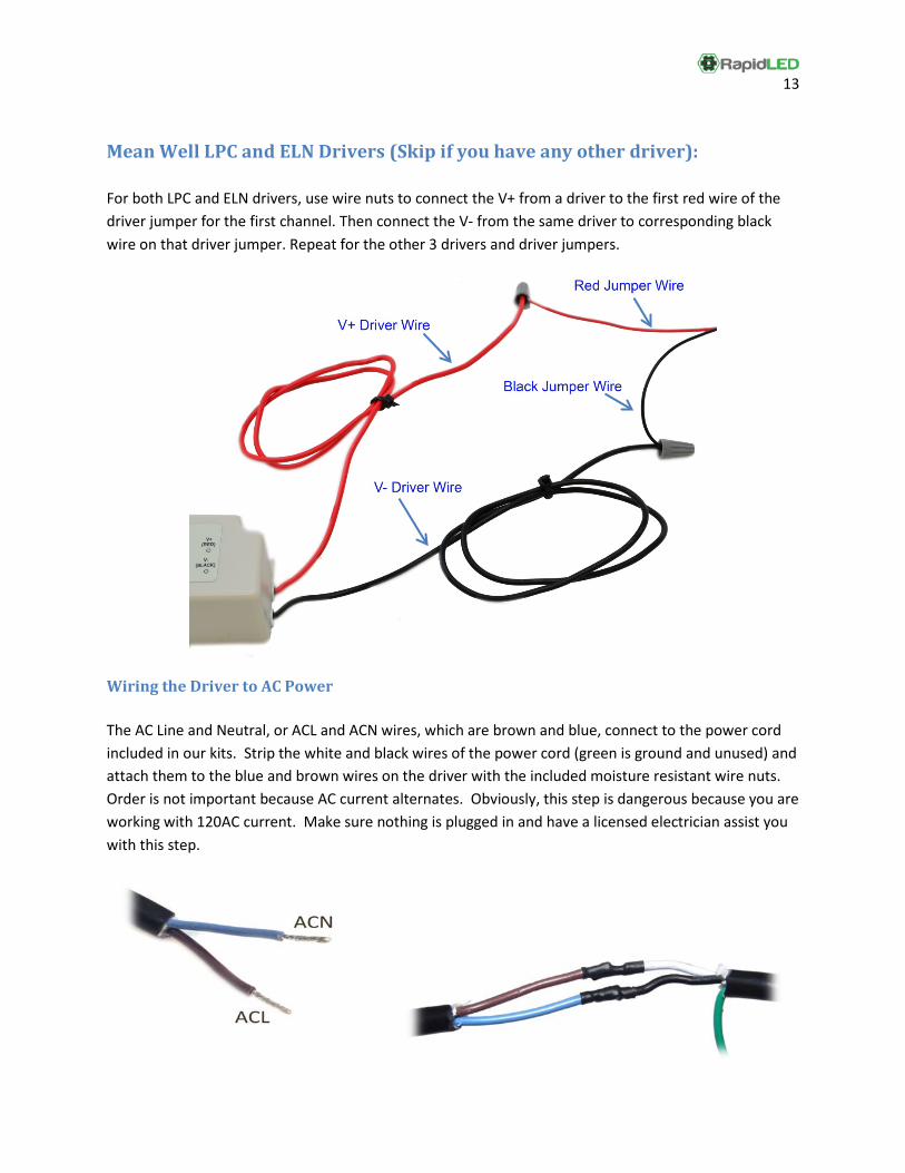
Mean Well LPC and ELN Drivers (Skip if you have any other driver): For both LPC and ELN drivers, use wire nuts to connect the V+ from a driver to the first red wire of the driver jumper for the first channel. Then connect the V- from the same driver to corresponding black wire on that driver jumper. Repeat for the other 3 drivers and driver jumpers.
Wiring the Driver to AC Power The AC Line and Neutral, or ACL and ACN wires, which are brown and blue, connect to the power cord included in our kits. Strip the white and black wires of the power cord (green is ground and unused) and attach them to the blue and brown wires on the driver with the included moisture resistant wire nuts. Order is not important because AC current alternates. Obviously, this step is dangerous because you are working with 120AC current. Make sure nothing is plugged in and have a licensed electrician assist you with this step.
14
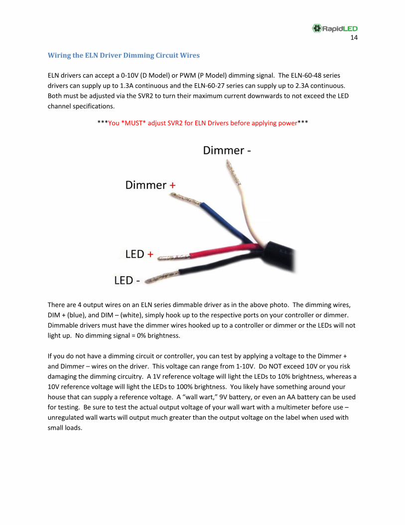
Wiring the ELN Driver Dimming Circuit Wires ELN drivers can accept a 0-10V (D Model) or PWM (P Model) dimming signal. The ELN-60-48 series drivers can supply up to 1.3A continuous and the ELN-60-27 series can supply up to 2.3A continuous. Both must be adjusted via the SVR2 to turn their maximum current downwards to not exceed the LED channel specifications.
***You *MUST* adjust SVR2 for ELN Drivers before applying power***
There are 4 output wires on an ELN series dimmable driver as in the above photo. The dimming wires, DIM + (blue), and DIM – (white), simply hook up to the respective ports on your controller or dimmer. Dimmable drivers must have the dimmer wires hooked up to a controller or dimmer or the LEDs will not light up. No dimming signal = 0% brightness. If you do not have a dimming circuit or controller, you can test by applying a voltage to the Dimmer + and Dimmer – wires on the driver. This voltage can range from 1-10V. Do NOT exceed 10V or you risk damaging the dimming circuitry. A 1V reference voltage will light the LEDs to 10% brightness, whereas a 10V reference voltage will light the LEDs to 100% brightness. You likely have something around your house that can supply a reference voltage. A “wall wart,” 9V battery, or even an AA battery can be used for testing. Be sure to test the actual output voltage of your wall wart with a multimeter before use – unregulated wall warts will output much greater than the output voltage on the label when used with small loads.
15
Adjusting ELN Driver Current – Do this before applying any power
Please watch our Adjusting the SVR2 Tutorial at the link below to see a video demonstration of this procedure:
http://www.youtube.com/watch?v=IM06z8bmViM In this section we will adjust the SVR2, which is inside of the ELN driver, by setting it to minimum (fully counter-clockwise), hooking a multimeter up between one wire on the driver jumper and the LED driver, applying a 100% intensity dimming signal to the ELN driver, and then slowly rotating SVR2 clockwise to the desired current.
• The Current Rating and appropriate driver for each channel is: o Blue - 1000mA Maximum (Recommended: 700mA to 850mA) - ELN-60-48D or P o Color - 700mA Maximum (Recommended: 700mA) - ELN-60-48D or P o White - 1500mA Maximum (Recommended: 700mA to 1100mA) - ELN-60-27D or P o UV - 700mA Maximum (Recommended: 700mA) - ELN-60-27D or P
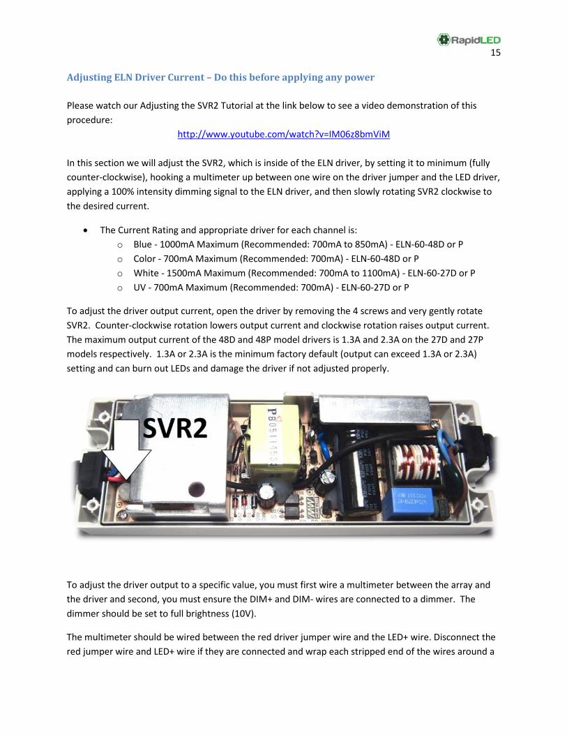
To adjust the driver output current, open the driver by removing the 4 screws and very gently rotate SVR2. Counter-clockwise rotation lowers output current and clockwise rotation raises output current. The maximum output current of the 48D and 48P model drivers is 1.3A and 2.3A on the 27D and 27P models respectively. 1.3A or 2.3A is the minimum factory default (output can exceed 1.3A or 2.3A) setting and can burn out LEDs and damage the driver if not adjusted properly.
To adjust the driver output to a specific value, you must first wire a multimeter between the array and the driver and second, you must ensure the DIM+ and DIM- wires are connected to a dimmer. The dimmer should be set to full brightness (10V).
The multimeter should be wired between the red driver jumper wire and the LED+ wire. Disconnect the red jumper wire and LED+ wire if they are connected and wrap each stripped end of the wires around a

16
prong from the meter. The black jumper wire and the LED- wire should be connected. If you wire the multimeter in backwards, it will still work, but your measurements will be negative instead of positive.
To set your multimeter up for measuring current, move the RED probe to the 10A socket and rotate the knob to the 10A position. Multimeters can differ in operation. Please consult your multimeter manual for model specific operating instructions.
The following should be complete before applying power to the driver:
• SVR2 has been gently rotated counter-clockwise until it stops (set to minimum current) • DIM+ and DIM- wires on driver are connected to a dimmer • Dimmer is set to 100% brightness (10VDC MAX) • Multimeter is turned on and set up to measure current • Multimeter is wired between the red driver jumper wire and the LED+ driver wire, and the black
jumper wire and LED- driver wires are connected.
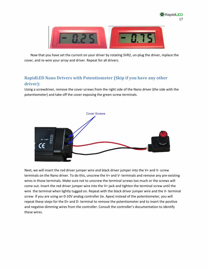
Once all of the above have been completed, power the driver and rotate SVR2 clockwise until the readout on the multimeter displays the desired output current for 100% brightness. In the below photos, the current begins at .25A, or 250mA. SVR2 was rotated clockwise until the desired maximum current, .75A, or 750mA. In our example, we wired our probes backwards, thus the – sign. When measuring current, you can ignore the – sign because we are only interested in the absolute amount of current flowing through the LED string. Switching the multimeter leads around would have would have flipped the sign around to +(no sign) in this example.
17
Now that you have set the current on your driver by rotating SVR2, un-plug the driver, replace the cover, and re-wire your array and driver. Repeat for all drivers.
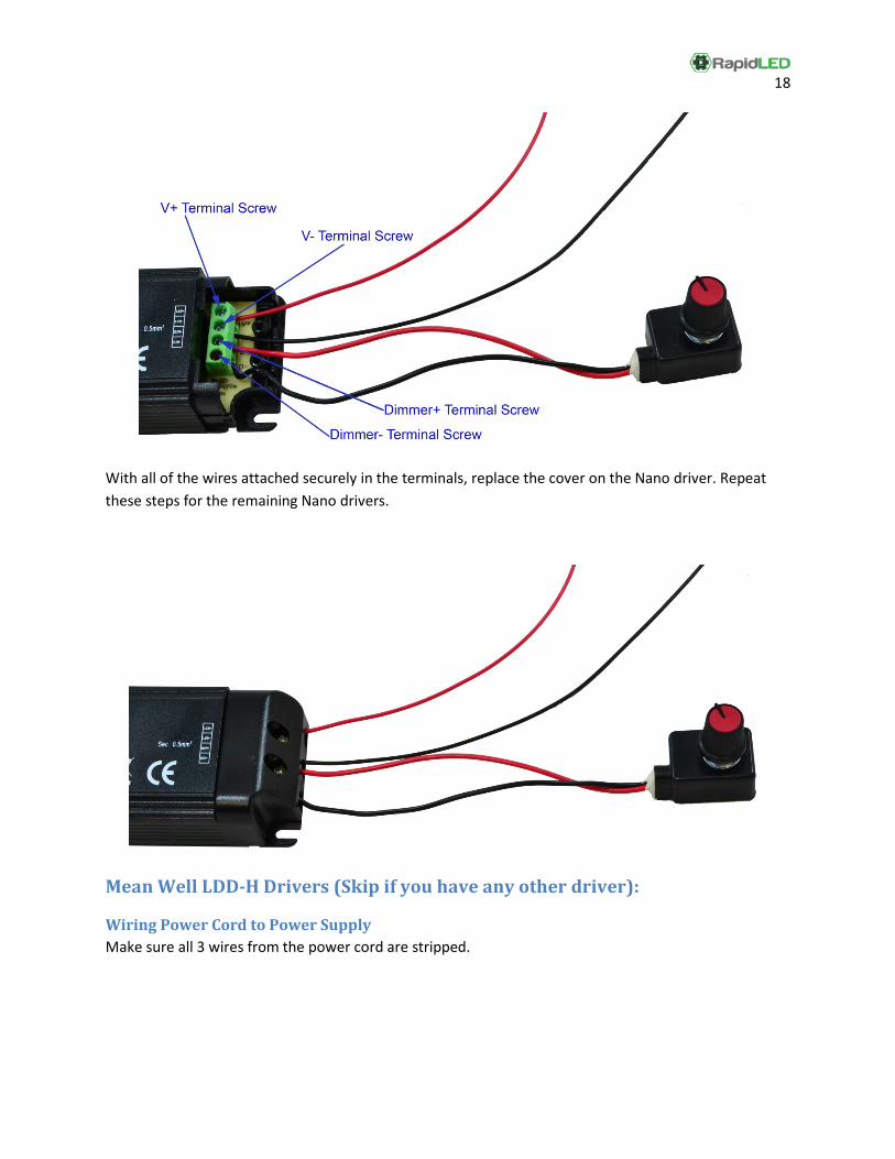
RapidLED Nano Drivers with Potentiometer (Skip if you have any other driver): Using a screwdriver, remove the cover screws from the right side of the Nano driver (the side with the potentiometer) and take off the cover exposing the green screw terminals.
Next, we will insert the red driver jumper wire and black driver jumper into the V+ and V- screw terminals on the Nano driver. To do this, unscrew the V+ and V- terminals and remove any pre-existing wires in those terminals. Make sure not to unscrew the terminal screws too much or the screws will come out. Insert the red driver jumper wire into the V+ jack and tighten the terminal screw until the wire the terminal when lightly tugged on. Repeat with the black driver jumper wire and the V- terminal screw. If you are using an 0-10V analog controller (ie. Apex) instead of the potentiometer, you will repeat these steps for the D+ and D- terminal to remove the potentiometer and to insert the positive and negative dimming wires from the controller. Consult the controller’s documentation to identify these wires.
18
With all of the wires attached securely in the terminals, replace the cover on the Nano driver. Repeat these steps for the remaining Nano drivers.
Mean Well LDD-H Drivers (Skip if you have any other driver):
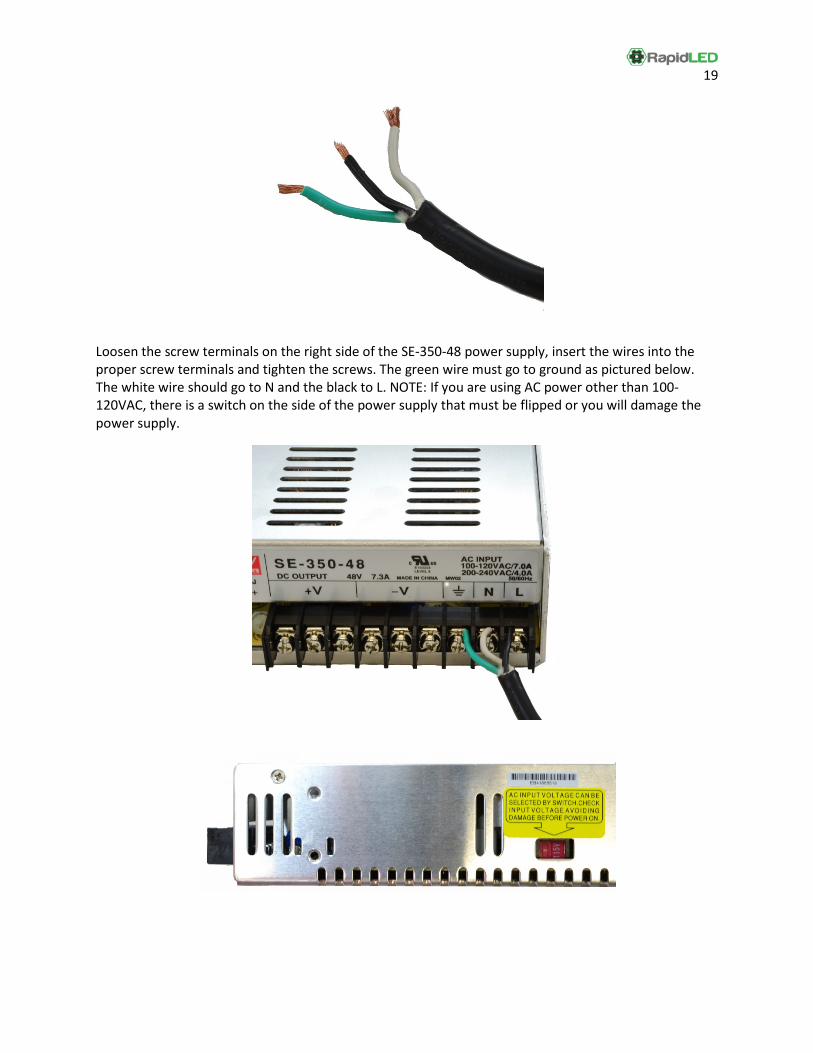
Wiring Power Cord to Power Supply Make sure all 3 wires from the power cord are stripped.
19
Loosen the screw terminals on the right side of the SE-350-48 power supply, insert the wires into the proper screw terminals and tighten the screws. The green wire must go to ground as pictured below. The white wire should go to N and the black to L. NOTE: If you are using AC power other than 100-120VAC, there is a switch on the side of the power supply that must be flipped or you will damage the power supply.
20
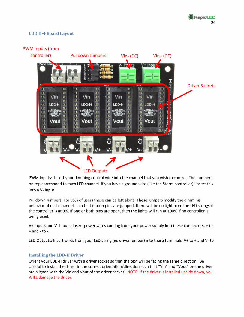
LDD H-4 Board Layout
PWM Inputs: Insert your dimming control wire into the channel that you wish to control. The numbers on top correspond to each LED channel. If you have a ground wire (like the Storm controller), insert this into a V- Input.
Pulldown Jumpers: For 95% of users these can be left alone. These jumpers modify the dimming behavior of each channel such that if both pins are jumped, there will be no light from the LED strings if the controller is at 0%. If one or both pins are open, then the lights will run at 100% if no controller is being used.
V+ Inputs and V- Inputs: Insert power wires coming from your power supply into these connectors, + to + and - to -.
LED Outputs: Insert wires from your LED string (ie. driver jumper) into these terminals, V+ to + and V- to -.
Installing the LDD-H Driver Orient your LDD-H driver with a driver socket so that the text will be facing the same direction. Be careful to install the driver in the correct orientation/direction such that “Vin” and “Vout” on the driver are aligned with the Vin and Vout of the driver socket. NOTE: If the driver is installed upside down, you WILL damage the driver.
Driver Sockets
PWM Inputs (from controller) Pulldown Jumpers
LED Outputs
Vin+ (DC) Vin- (DC)
21
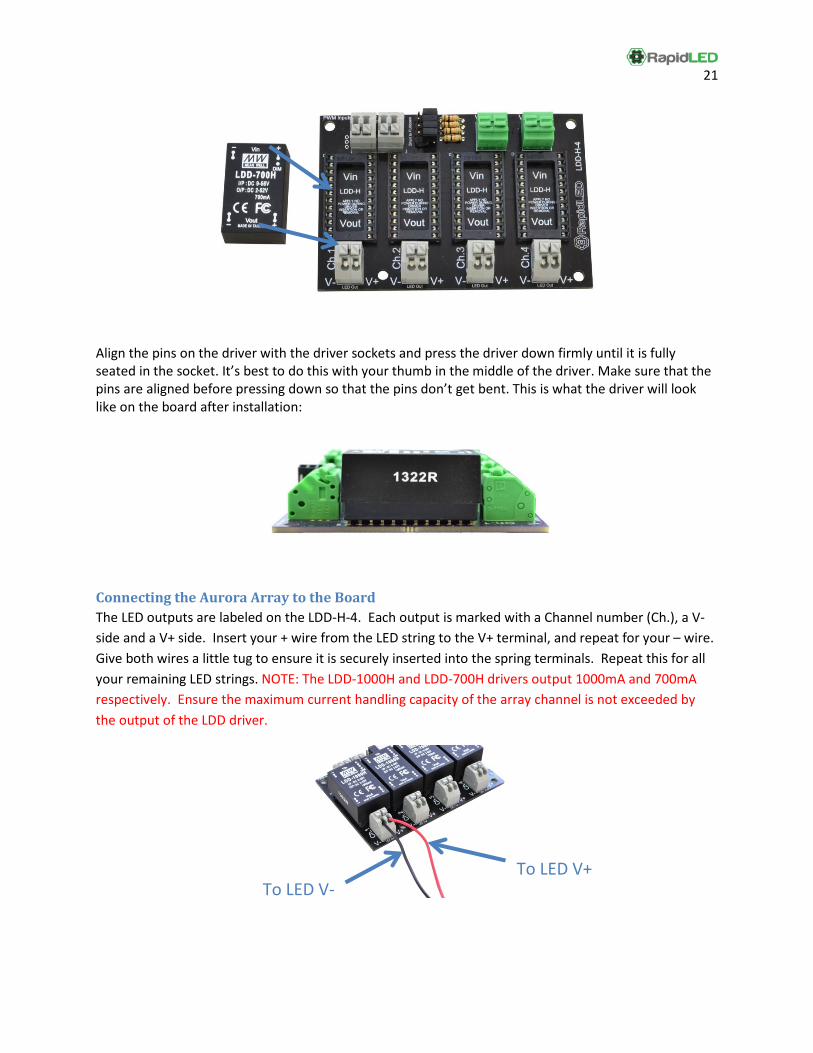
Align the pins on the driver with the driver sockets and press the driver down firmly until it is fully seated in the socket. It’s best to do this with your thumb in the middle of the driver. Make sure that the pins are aligned before pressing down so that the pins don’t get bent. This is what the driver will look like on the board after installation:
Connecting the Aurora Array to the Board The LED outputs are labeled on the LDD-H-4. Each output is marked with a Channel number (Ch.), a V- side and a V+ side. Insert your + wire from the LED string to the V+ terminal, and repeat for your – wire. Give both wires a little tug to ensure it is securely inserted into the spring terminals. Repeat this for all your remaining LED strings. NOTE: The LDD-1000H and LDD-700H drivers output 1000mA and 700mA respectively. Ensure the maximum current handling capacity of the array channel is not exceeded by the output of the LDD driver.
To LED V- To LED V+
22
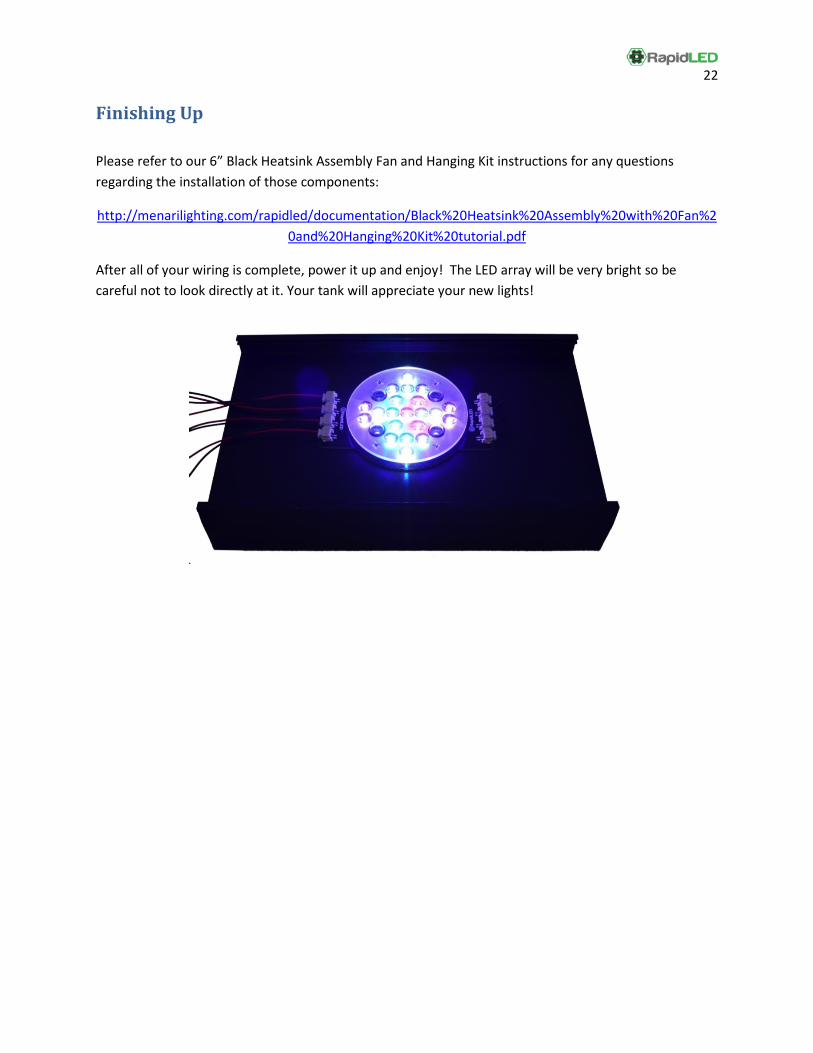
Finishing Up Please refer to our 6” Black Heatsink Assembly Fan and Hanging Kit instructions for any questions regarding the installation of those components:
http://menarilighting.com/rapidled/documentation/Black%20Heatsink%20Assembly%20with%20Fan%20and%20Hanging%20Kit%20tutorial.pdf
After all of your wiring is complete, power it up and enjoy! The LED array will be very bright so be careful not to look directly at it. Your tank will appreciate your new lights!