razr2 razr3 razr4 install guide · pdf fileoverview the fluence razr2, razr3 & razr4...
TRANSCRIPT

RAZR2-RAZR3-RAZR4
INSTALL GUIDE
171201
70619A

OVERVIEW The Fluence RAZR2, RAZR3 & RAZR4 solutions utilize a central power supply enclosure to drive a full array of modules. These modules daisy-chain together across a horizontal area, or can be paired with a T-harness for vertical stacking on racks or shelving. The power supply enclosure has a dimming port to control light intensity across the full array of modules from 0-100% (dimmer sold separately). For best results, please consult the table below for optimal mounting heights and PPFD levels before continuing with install.
Product Number of Modules PPF Per Module Recommended
Mounting Height PPFD at Recommended
Mounting Height
RAZR2 10 140 µmol/s 12 inches Avg. 125-160 µmol/m2/s*
RAZR3 7 200 µmol/s 8 inches Avg. 215-260 µmol/m2/s*
RAZR4 5 280 µmol/s 5 inches Avg. 310-375 µmol/m2/s*
*PPFD averages vary based on deployment of RAZR modules. Higher PPFD is achieved when deployed horizontally with light-overlap.
PLEASE NOTE: Do not mix RAZR2, RAZR3 & RAZR4 modules together on the same power supply enclosure.

TO INSTALL RAZR2, RAZR3 AND/OR RAZR4 MODULES HORIZONTALLY YOU WILL NEED:
RAZR Modules
Zip Ties Two People
Power Supply Enclosure

Each module has a male and female DC cord extending from opposite sides of the frame. Ensure you arrange the first module in the series with the male connector facing toward the power supply enclosure.
IMPORTANT!
Male Connector
First Module Power Supply Enclosure

Carefully unbox the RAZR modules and arrange them face down under the rack you wish to mount them on. Start by removing the dust cap from the female DC connector. The female connectors daisy-chain to the next modules in the series.
Prepare Modules for Mounting 1
Remove Dust Cap Covering Female
Connector
Point Male Connector Toward Power Supply
Enclosure

With one person on each side of the rack, hold the first module flush to the underside of the rack. Use the provided zip ties to secure the module to the rack. Place zip ties on the inside of the outer bars to insure the module can’t slip out. If zip ties do not work for your application, please use the mounting holes on each corner to bolt or screw the module into place.
Install the 1st RAZR Module 2
Zip Ties
Corner Mounting Holes

Remove the dust cap from the second module and position it next to the first so that the spacing between light-bars is uniform across the two modules. Zip tie the second module into place after spacing adjustments have been made, and then connect the two modules.
Install the 2nd RAZR Module 3
Maintain Equal Spacing Between Light Bars For Optimal Light Uniformity
Connect First & Second Modules

Repeat Step 3 for the remaining modules. One power supply enclosure can power up to 5 RAZR4 modules, 7 RAZR3 modules or 10 RAZR2 modules when daisy-chained in a series. Do not mix RAZR2, RAZR3 and RAZR4 modules together during installation.
Connect the Remaining Modules 4

Use the included wire-form hangers to mount the enclosure on the side or end of the rack, or use the keyhole slots with fasteners or dry-wall anchors to remotely mount on a nearby wall.
Mount Enclosure to Rack or Wall 5
Keyhole Slots for Wall Mounting
Wire-form Hangers for Rack Mounting

After all modules have been installed, connect the provided DC cable extender to the male connector of the first module. Connect the other end of the DC cable extender to the power supply enclosure port marked “DC OUT”.
Connect Modules to the Enclosure 6
Wall Mounted Enclosure Rack Mounted Enclosure
Connect First Module to Enclosure

To power the array of modules, connect the power supply enclosure port marked “AC IN” to a nearby receptacle using the provided AC power cord. To avoid power surges that might damage your modules, always connect the power supply enclosure to the wall last. To dim the modules, connect a 0-10V dimmer (sold separately) to the “DIM” port located next to the “DC OUT” port. When not dimming the modules, the dimming port cap must remain attached or the modules will power off.
Connect Enclosure to Power 7
DC Cable to First Module
Connect Enclosure to Power Outlet with AC Cable
Dimming Port With Cap

TO INSTALL RAZR2, RAZR3 AND/OR RAZR4 MODULES VERTICALLY YOU WILL NEED:
RAZR Modules
Zip Ties Two People
T-Harness*
* T-Harness sold separately.
Power Supply Enclosure

Each module has a male and female DC cord extending from opposite sides of the frame. Ensure the male connector of the first module in the series and the male connector on the T-harness are facing toward the power supply enclosure.
IMPORTANT!
Male Connectors
Power Supply Enclosure First Module

Carefully unbox the RAZR modules and arrange them face down under the shelf you wish to mount them on. Start by removing the dust cap from the female DC connector. The female connectors daisy-chain to the next modules in the series.
Prepare Modules for Mounting 1
Remove Dust Cap Covering Female
Connector
Point Male Connector Toward Power Supply
Enclosure

Lift and center the first module flush to the underside of the top shelf. Use the included zip ties to secure all four corners of the module to the shelf above it. Place zip ties between the middle and outside bars to guarantee the module can’t slip out. If zip ties do not work for your application, please use the mounting holes on each corner to bolt or screw the module into place.
Install the First RAZR Module 2
Connect Enclosure to Power Outlet with AC Cable
Zip Ties
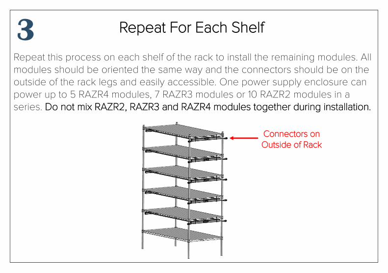
Repeat this process on each shelf of the rack to install the remaining modules. All modules should be oriented the same way and the connectors should be on the outside of the rack legs and easily accessible. One power supply enclosure can power up to 5 RAZR4 modules, 7 RAZR3 modules or 10 RAZR2 modules in a series. Do not mix RAZR2, RAZR3 and RAZR4 modules together during installation.
Repeat For Each Shelf 3
Connectors on Outside of Rack

Starting with the lowest shelf, attach the T-harness to the first module and work upward to connect the rest of the modules. Cover the unused connector at the very bottom of the T-harness with a dust cap to prevent dust or water intrusion.
Attach T-Harness to Modules 4
Cover Unused Female Connector with Dust Cap
Male Connector Facing Power
Supply Enclosure

Use the included wire-form hangers to mount the enclosure on the side or end of a rack, or use the keyhole slots with fasteners or dry-wall anchors to remotely mount to a nearby wall.
Mount Enclosure to Rack or Wall 5
Keyhole Slots for Wall Mounting
Wire-form Hangers for Rack Mounting

After all modules have been installed, connect the 3 or 6 foot DC cable to the male connector of the first module. Connect the other end of the DC cable to the power supply enclosure port marked “DC OUT”.
Connect Modules to the Enclosure 6
Wall Mounted Enclosure Rack Mounted Enclosure
Connect First Module to Enclosure

To power the array of modules, connect the power supply enclosure port marked “AC IN” to a nearby receptacle using the provided AC power cord. To avoid power surges that might damage your modules, always connect the power supply enclosure to the wall last. To dim the modules, connect a 0-10V dimmer (sold separately) to the “DIM” port located next to the “DC OUT” port. When not dimming the modules, the dimming port cap must remain attached or the modules will power off.
Connect Enclosure to Power 7
DC Cable to First Module
Connect Enclosure to Power Outlet with AC Cable
Dimming Port With Cap