rc design ppt
DESCRIPTION
RC DESIGN USING STAADTRANSCRIPT
MODULE 04
REINFORCED CONCRETE DESIGN & STAAD Pro
Allan E. Botuyan, MSCE
OUTLINE
1. INTRODUCTION2. BEAM DESIGN
2.1. FLEXURE2.2. SHEAR & TORSION2.3. DESIGN FOR ANCHORAGE2.4. STAAD PRO INPUT PARAMETERS2.5. STAD DESIGN OUTPUT FOR BEAMS2.6. SEISMIC REQUIREMENTS FOR BEAMS
OUTLINE
3. COLUMN DESIGN3.1. COLUMN INTERACTION DIAGRAM3.2. STAAD DESIGN BRIEF FOR COLUMNS 3.3. STAAD DESIGN OUTPUT FOR
COLUMNS3.4 SEISMIC REQUIREMENTS FOR
COLUMNS
4. DESIGN IN STAAD PRO
• Analysis part is always followed by the design part.
• The design of members is based on the critical member forces
I. INTRODUCTION
• What are the critical member forces use for design?
• ANALYSIS RESULTS based on loads and load combinations
• Vertical loads = dead and live loads• Seismic loads = static or dynamic loads
• P-delta effects• Horizontal torsional moments• Orthogonal effects
• Load combinations
I. INTRODUCTION
Seismic Loads• P-delta Effects
I. INTRODUCTION
I. INTRODUCTION
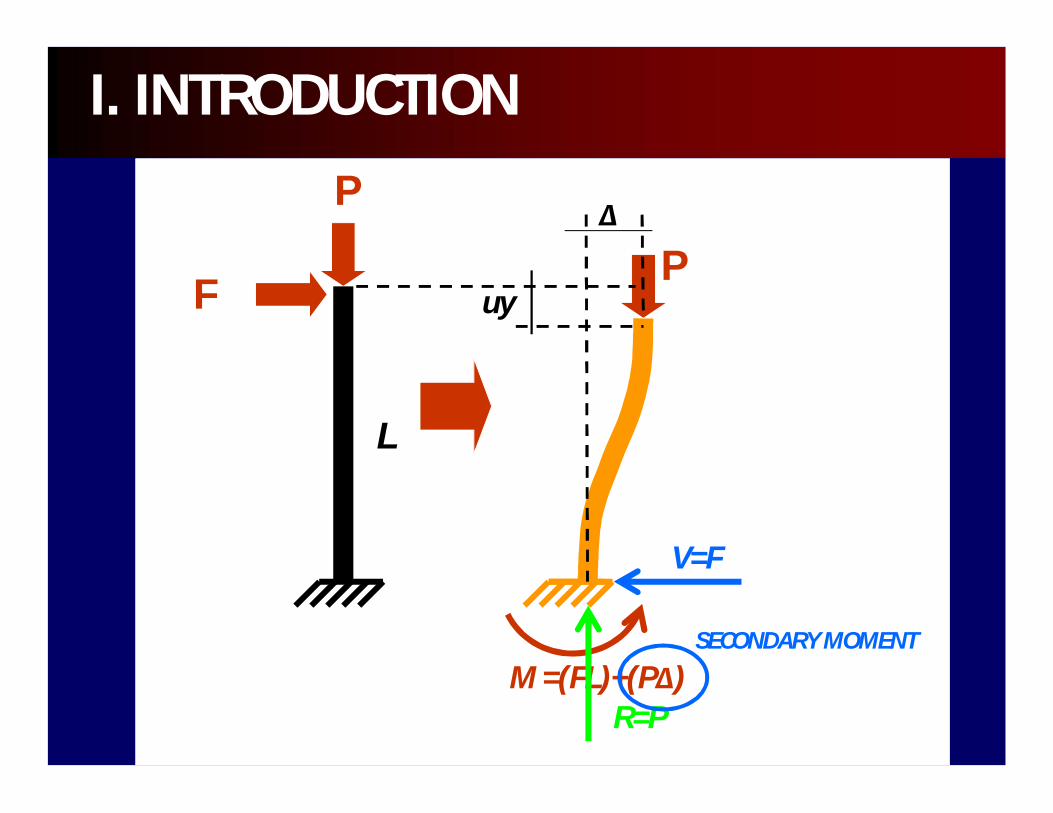
F
P
L
Δ
uyP
M =(FL)+(PΔ)R=P
SECONDARY MOMENT
V=F

I. INTRODUCTION
Pi = Pd+PlΔ
Vi –story shear
Vi – story shear
Story height, hi
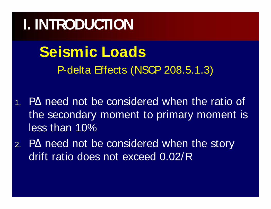
Seismic LoadsP-delta Effects (NSCP 208.5.1.3)
1. PΔ need not be considered when the ratio of the secondary moment to primary moment is less than 10%
2. PΔ need not be considered when the story drift ratio does not exceed 0.02/R
I. INTRODUCTION
Seismic LoadsHorizontal Torsional Moments (NSCP 208.5.7)
The accidental torsion shall be determined by assuming the mass is displaced 5% of the building width.
I. INTRODUCTION
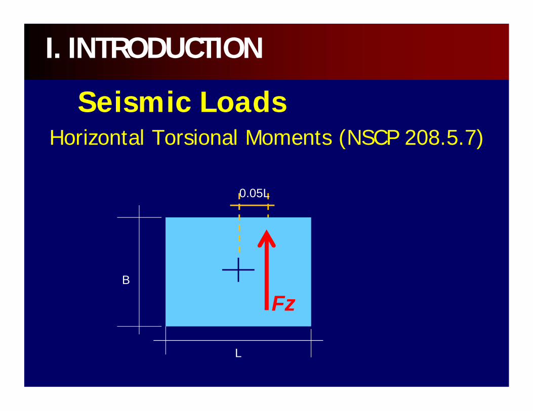
Seismic LoadsHorizontal Torsional Moments (NSCP 208.5.7)
I. INTRODUCTION
B
L
0.05L
Fz
I. INTRODUCTION
B
L
0.05BFx
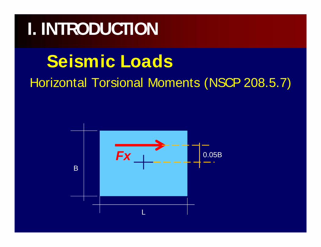
Seismic LoadsHorizontal Torsional Moments (NSCP 208.5.7)
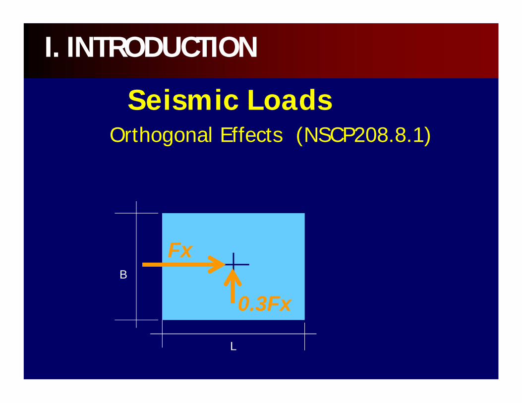
Seismic LoadsOrthogonal Effects (NSCP208.8.1)
I. INTRODUCTION
B
L
Fx
0.3Fx

I. INTRODUCTION
B
L
0.3Fy
Fy
Seismic LoadsOrthogonal Effects (NSCP208.8.1)
• note that the initial proportioning of beam and column sizes is part of the design and may not be the final dimension.
• design is a series of iteration and resizing, then reanalysis, then redesign.
I. INTRODUCTION
Design is an iteration process:1. Initial sizing of beams and columns.2. Analysis for stresses.3. Design of steel reinforcements.
if design is inadequate, repeat step 1, 2, and 3.
4. If design is adequate, adopt sizes and reinforcements.
5. Apply seismic detailing
I. INTRODUCTION
• All concrete design calculation is governed by the current ACI 318 code.
• Unified (strength) design method is adopted by the current code.
• The working stress design (WSD) is deletedfrom the ACI 318 code
• STAAD Pro does not employ the WSD for reinforced concrete design.
I. INTRODUCTION
• SPECIAL MOMENT RESISTING FRAMES (SMRF) are the type of frames, instead of ORDINARY MOMENT RESISTING FRAMES (OMRF), are required for high seismic risk areas, such as the Philippines.
• Therefore, the NSCP requires that all buildings in the Philippines must be designed to effectively resist high seismic forces.
I. INTRODUCTION
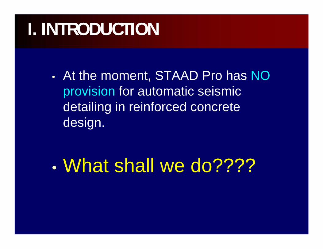
• At the moment, STAAD Pro has NO provision for automatic seismic detailing in reinforced concrete design.
• What shall we do????
I. INTRODUCTION
• FLEXURE
• SHEAR
• TORSION
2. BEAM DESIGN
2.1. FLEXUREThe main (longitudinal) reinforcement is calculated for midspan (sagging) and support (hogging) bending moments on the basis of the section profile in the design brief (ie. PRISMATIC ZD, YD).
2. BEAM DESIGN
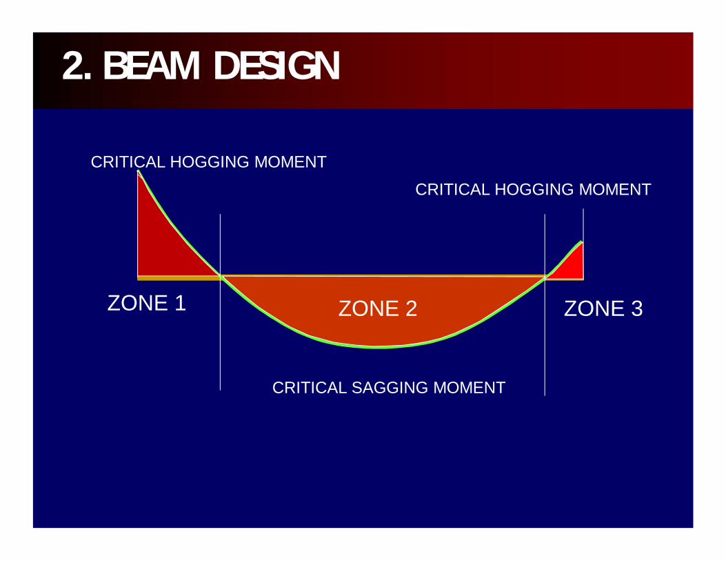
CRITICAL SAGGING MOMENT
CRITICAL HOGGING MOMENT
CRITICAL HOGGING MOMENT
ZONE 1 ZONE 2 ZONE 3
2. BEAM DESIGN

2.1. FLEXUREThe STAAD Pro does not have any limit of any bars in any one layer as long as the spacing requirements specified in the code are satisfied.
The program can handle a maximum of four layers of reinforcement, two layers each at the top and bottom.
2. BEAM DESIGN

2.1. FLEXUREThe actual amount of steel required as well as the maximum and minimum required for flexure is shown as ROW, ROWMX AND ROWMIN, respectively.
It is important to note that the beams are designed for flexural MZ only. The moment My is not considered in the design.
2. BEAM DESIGN

b
h x
MY
y
MZ
Top bars (max of 2 layers)
2.1. FLEXURE
bottom bars (max of 2 layers)
2. BEAM DESIGN

d
SFACE OR
EFACE
BEAM ELEMENT LINE
COLUMN ELEMENT LINE
STEEL REINFORCEMENTS
2. BEAM DESIGN
2.2. SHEAR & TORSION
When required, torsional reinforcement in the form of closed stirrups or hoop reinforcement must be provided.
2. BEAM DESIGN
2.2. SHEAR & TORSION

2. BEAM DESIGN
2.2. SHEAR & TORSION
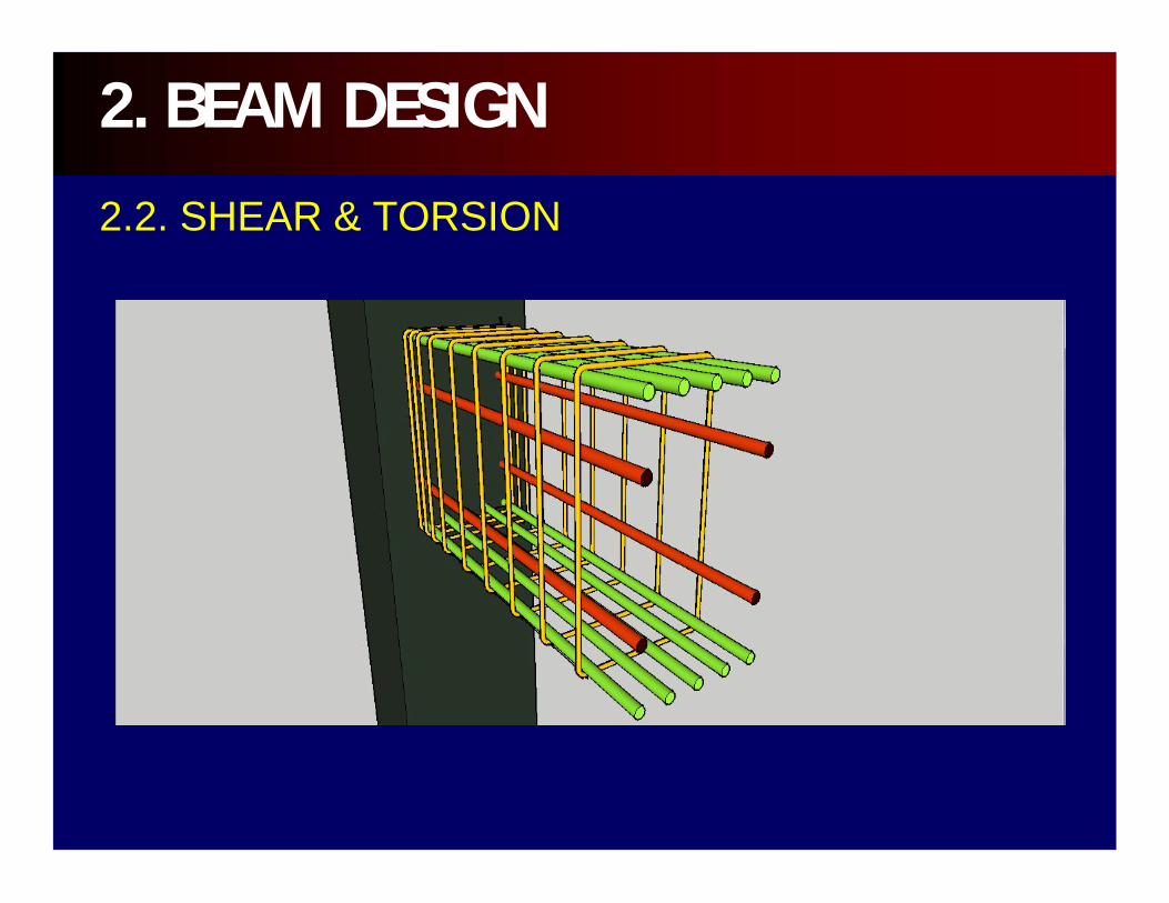
In addition to the stirrups, longitudinal steel bars are provided in corners of the stirrups and are well distributed around the section
2. BEAM DESIGN
2.2. SHEAR & TORSION
2.2. SHEAR & TORSION
2. BEAM DESIGN
In the ACI Code, the design for torsion is based on space truss analogy.
After torsional cracking occurs, the torque is resisted by closed stirrups, longitudinal bars, and concrete compression diagonals.
2.2. SHEAR & TORSION
2. BEAM DESIGN
2.3. DESIGN FOR ANCHORAGEIn STAAD output for flexural design, the anchorage requirement is shown with a YES or NO at the START and END of the beam. The designer must provide the details of anchorage.
2. BEAM DESIGN

4db
5db
6db
4db or 2.5” min
D
10mm to 20mm (D=6db)28mm, 32mm, 36mm (D=8db)43mm, 57mm (D=10db)
Hook if anchor is YES at START and/orEND node
Critical section (eg. Interior column face)
Ldh- development length
ExteriorColumnface
12dbdb –bar diameter
db –bar diameter
2. BEAM DESIGN
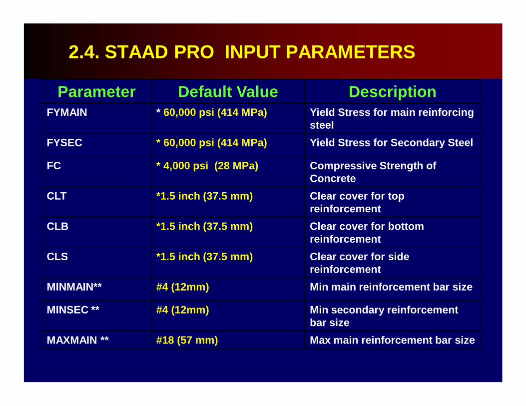
2.4. STAAD PRO INPUT PARAMETERS
Parameter Default Value DescriptionFYMAIN * 60,000 psi (414 MPa) Yield Stress for main reinforcing
steelFYSEC * 60,000 psi (414 MPa) Yield Stress for Secondary Steel
FC * 4,000 psi (28 MPa) Compressive Strength of Concrete
CLT *1.5 inch (37.5 mm) Clear cover for top reinforcement
CLB *1.5 inch (37.5 mm) Clear cover for bottom reinforcement
CLS *1.5 inch (37.5 mm) Clear cover for side reinforcement
MINMAIN** #4 (12mm) Min main reinforcement bar size
MINSEC ** #4 (12mm) Min secondary reinforcement bar size
MAXMAIN ** #18 (57 mm) Max main reinforcement bar size
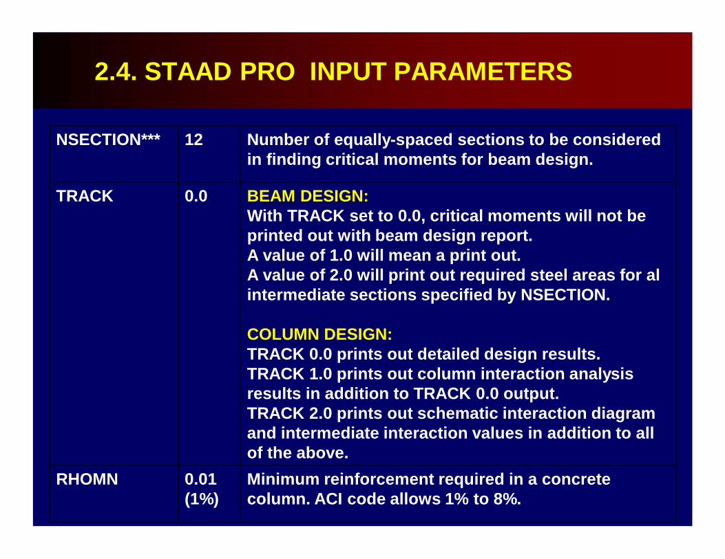
NSECTION*** 12 Number of equally-spaced sections to be considered in finding critical moments for beam design.
TRACK 0.0 BEAM DESIGN:With TRACK set to 0.0, critical moments will not be printed out with beam design report.A value of 1.0 will mean a print out.A value of 2.0 will print out required steel areas for al intermediate sections specified by NSECTION.
COLUMN DESIGN:TRACK 0.0 prints out detailed design results.TRACK 1.0 prints out column interaction analysis results in addition to TRACK 0.0 output.TRACK 2.0 prints out schematic interaction diagram and intermediate interaction values in addition to all of the above.
RHOMN 0.01 (1%)
Minimum reinforcement required in a concrete column. ACI code allows 1% to 8%.
2.4. STAAD PRO INPUT PARAMETERS

UNIT KN METERSTART CONCRETE DESIGNCODE ACI 2002FYMAIN 414 ALLMAXMAIN 20 ALLCLB 40MMDESIGN BEAM 17 10END CONCRETE DESIGN
EXAMPLE DESIGN BRIEF FOR BEAMS
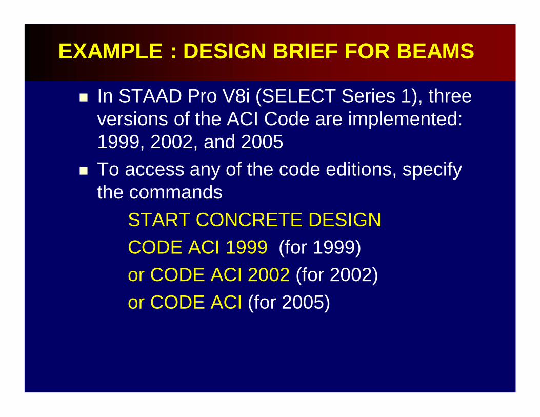
In STAAD Pro V8i (SELECT Series 1), three versions of the ACI Code are implemented: 1999, 2002, and 2005
To access any of the code editions, specify the commands
START CONCRETE DESIGNCODE ACI 1999 (for 1999)or CODE ACI 2002 (for 2002) or CODE ACI (for 2005)
EXAMPLE : DESIGN BRIEF FOR BEAMS
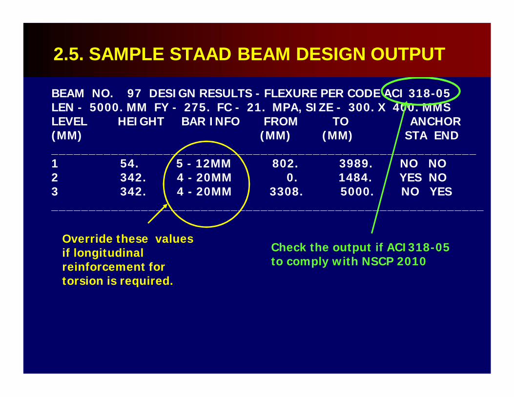
BEAM NO. 97 DESIGN RESULTS - FLEXURE PER CODE ACI 318-05LEN - 5000. MM FY - 275. FC - 21. MPA, SIZE - 300. X 400. MMSLEVEL HEIGHT BAR INFO FROM TO ANCHOR(MM) (MM) (MM) STA END_________________________________________________________1 54. 5 - 12MM 802. 3989. NO NO2 342. 4 - 20MM 0. 1484. YES NO3 342. 4 - 20MM 3308. 5000. NO YES__________________________________________________________
Check the output if ACI318-05 to comply with NSCP 2010
Override these values if longitudinal reinforcement for torsion is required.
2.5. SAMPLE STAAD BEAM DESIGN OUTPUT
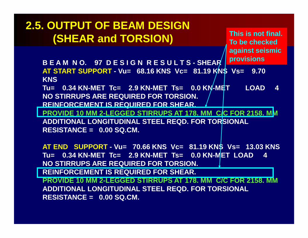
B E A M N O. 97 D E S I G N R E S U L T S - SHEARAT START SUPPORT - Vu= 68.16 KNS Vc= 81.19 KNS Vs= 9.70 KNSTu= 0.34 KN-MET Tc= 2.9 KN-MET Ts= 0.0 KN-MET LOAD 4NO STIRRUPS ARE REQUIRED FOR TORSION.REINFORCEMENT IS REQUIRED FOR SHEAR.PROVIDE 10 MM 2-LEGGED STIRRUPS AT 178. MM C/C FOR 2158. MMADDITIONAL LONGITUDINAL STEEL REQD. FOR TORSIONAL RESISTANCE = 0.00 SQ.CM.
AT END SUPPORT - Vu= 70.66 KNS Vc= 81.19 KNS Vs= 13.03 KNSTu= 0.34 KN-MET Tc= 2.9 KN-MET Ts= 0.0 KN-MET LOAD 4NO STIRRUPS ARE REQUIRED FOR TORSION.REINFORCEMENT IS REQUIRED FOR SHEAR.PROVIDE 10 MM 2-LEGGED STIRRUPS AT 178. MM C/C FOR 2158. MMADDITIONAL LONGITUDINAL STEEL REQD. FOR TORSIONAL RESISTANCE = 0.00 SQ.CM.
2.5. OUTPUT OF BEAM DESIGN (SHEAR and TORSION) This is not final.
To be checked against seismic provisions
Since the Philippines is located in a high seismic risk region, adopting the SMRF(Special Moment Resisting Frame) is a must.
Therefore, a special detailing for seismic requirement shall is required. Unfortunately, STAAD Pro at the moment does not have the facility for seismic detailing.
2.6. SEISMIC REQUIREMENTS FOR BEAMS
At this point the design output of STAAD Pro is compliant to ACI Code 318-08 or the NSCP 2010, EXCEPT FOR THE SEISMIC DETAILING requirements.
2.6. SEISMIC REQUIREMENTS FOR BEAMS
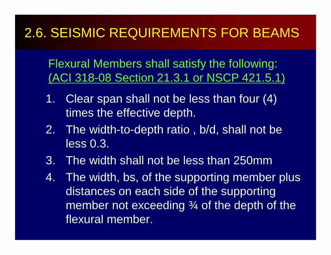
Flexural Members shall satisfy the following:(ACI 318-08 Section 21.3.1 or NSCP 421.5.1)
1. Clear span shall not be less than four (4) times the effective depth.
2. The width-to-depth ratio , b/d, shall not be less 0.3.
3. The width shall not be less than 250mm4. The width, bs, of the supporting member plus
distances on each side of the supporting member not exceeding ¾ of the depth of the flexural member.
2.6. SEISMIC REQUIREMENTS FOR BEAMS
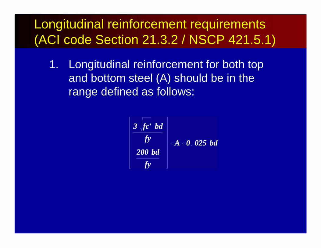
1. Longitudinal reinforcement for both top and bottom steel (A) should be in the range defined as follows:
3 fc' bdfy
200 bdfy
A 0 025 bd
Longitudinal reinforcement requirements (ACI code Section 21.3.2 / NSCP 421.5.1)
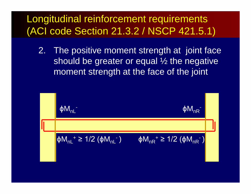
2. The positive moment strength at joint face should be greater or equal ½ the negative moment strength at the face of the joint
ϕMnL-
ϕMnL+ ≥ 1/2 (ϕMnL
- )
ϕMnR-
ϕMnR+ ≥ 1/2 (ϕMnR
- )
Longitudinal reinforcement requirements (ACI code Section 21.3.2 / NSCP 421.5.1)
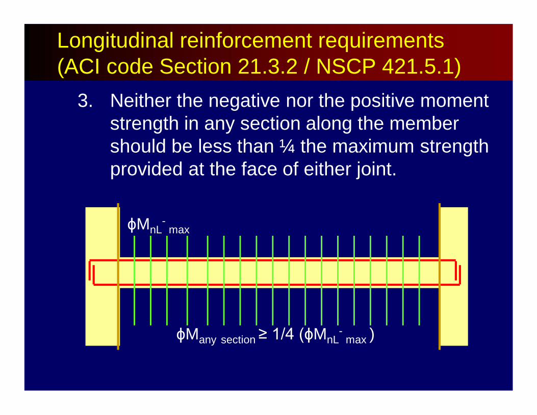
3. Neither the negative nor the positive moment strength in any section along the member should be less than ¼ the maximum strength provided at the face of either joint.
ϕMnL-
max
ϕMany section ≥ 1/4 (ϕMnL-
max )
Longitudinal reinforcement requirements (ACI code Section 21.3.2 / NSCP 421.5.1)
4. Lap splices of flexural reinforcement are permitted only if hoop reinforcement is provided over the lap length.
Maximum spacing of transverse reinforcement enclosing the lapped bars shall not exceed 100mm.
Longitudinal reinforcement requirements (ACI code Section 21.3.2 / NSCP 421.5.1)

Lap splices shall not be used:a. Within the joint.b. With a distance of twice the member depth
from the face of the joint; andc. At locations where analysis indicates flexural
yielding (ie. Location of plastic hinges)
Longitudinal reinforcement requirements (ACI code Section 21.3.2 / NSCP 421.5.1)
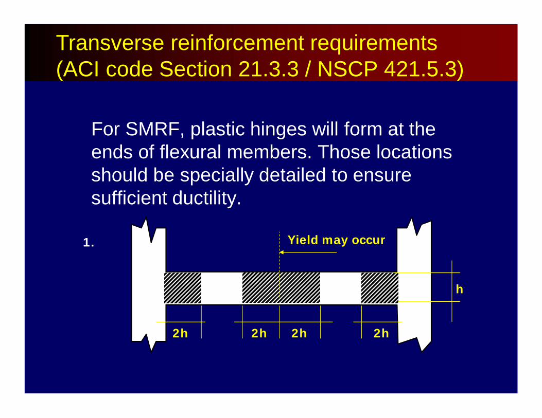
2h 2h 2h 2h
h
Yield may occur1.
Transverse reinforcement requirements (ACI code Section 21.3.3 / NSCP 421.5.3)
For SMRF, plastic hinges will form at the ends of flexural members. Those locations should be specially detailed to ensure sufficient ductility.
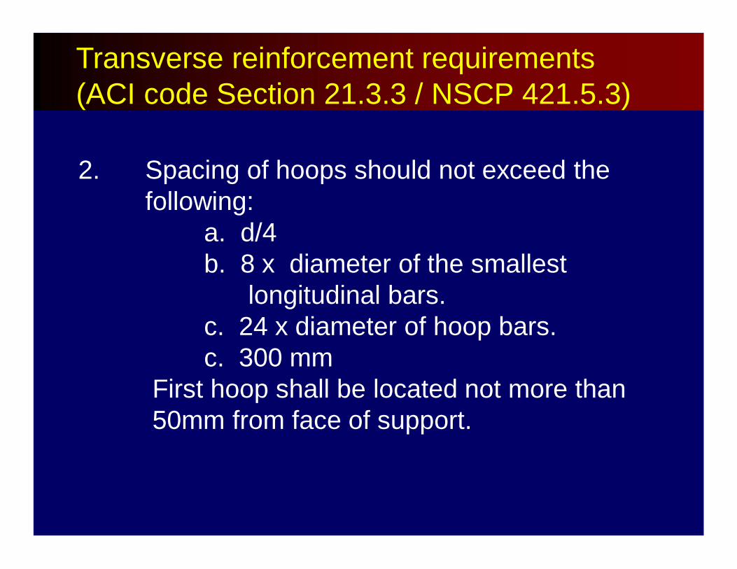
2. Spacing of hoops should not exceed the following:
a. d/4b. 8 x diameter of the smallest
longitudinal bars.c. 24 x diameter of hoop bars.c. 300 mm
First hoop shall be located not more than 50mm from face of support.
Transverse reinforcement requirements (ACI code Section 21.3.3 / NSCP 421.5.3)

3. Where hoops are not required, stirrups withseismic hooks shall be spaced at a distancenot more than d/2 throughout the lengthof the member.
Transverse reinforcement requirements (ACI code Section 21.3.3 / NSCP 421.5.3)
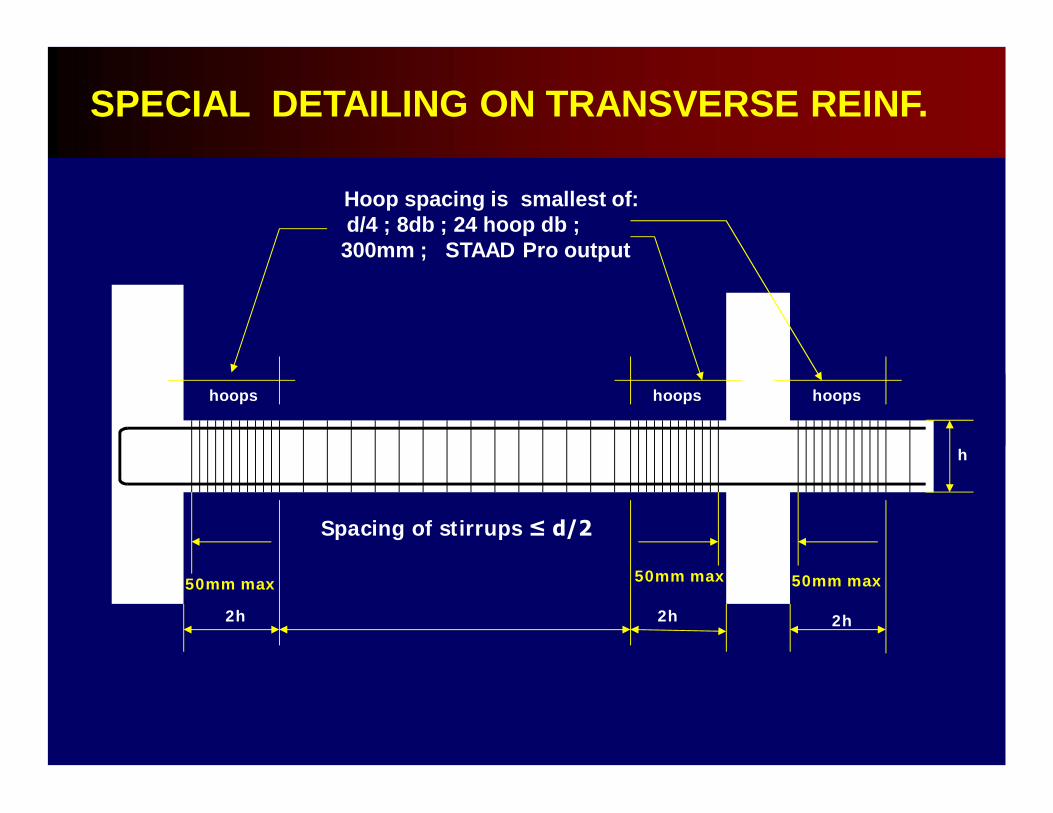
h
hoops
2h
50mm max 50mm max 50mm max
Hoop spacing is smallest of:d/4 ; 8db ; 24 hoop db ; 300mm ; STAAD Pro output
Spacing of stirrups ≤ d/2
hoops hoops
2h 2h
SPECIAL DETAILING ON TRANSVERSE REINF.

Sample of design output from STAAD Pro56J 5000 X 300 X 400 58J
4No20 H 342. | 0 TO 148414*10c/c 178
4No20 H 342. | 3308 TO 500014*10c/c178
5No12 H 54. | 802 TO 3989
5000
400
1484 1692
4-20mm 4-20mm
5-12mm 14 hoops of 10mm@ 178 o.c.14 hoops @10mm@ 178 o.c.
802 1102
Physical representation
54
342
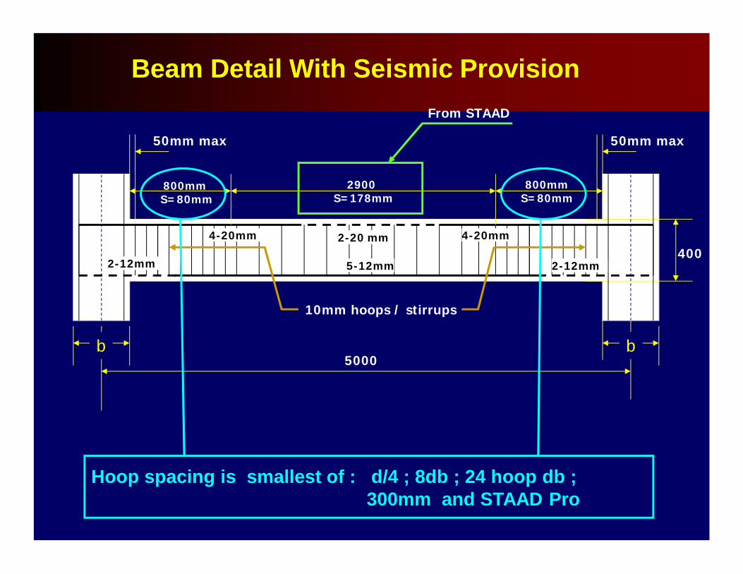
Beam Detail With Seismic Provision
400
800mm S=80mm
2900S=178mm
From STAAD
50mm max 50mm max
4-20mm
5-12mm
b
4-20mm
2-12mm2-12mm
10mm hoops / stirrups
2-20 mm
800mmS=80mm
b5000
Hoop spacing is smallest of : d/4 ; 8db ; 24 hoop db ; 300mm and STAAD Pro
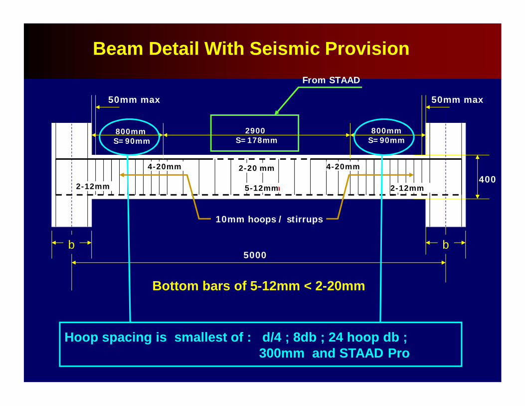
5000
400
800mm S=90mm
2900S=178mm
From STAAD
50mm max 50mm max
4-20mm
2-20mm
Hoop spacing is smallest of : d/4 ; 8db ; 24 hoop db ; 300mm and STAAD Pro
b
4-20mm
2-20mm2-20mm
10mm hoops / stirrups
2-20 mm
800mmS=90mm
b
Bottom bars of 5-12mm < 2-20mm
5-12mm 2-12mm2-12mm
Beam Detail With Seismic Provision
3. COLUMN DESIGN
Column design in STAAD per the ACI code is performed for axial force, uniaxialand biaxial moments.
The loading which produces the largest amount of reinforcement is called the critical load.
Column design is done for square, rectangular and circular sections.
For rectangular and circular sections, reinforcement is always assumed to be equally distributed on all faces. This means that the total number of bars will always be a multiple of four (4).
3. COLUMN DESIGN
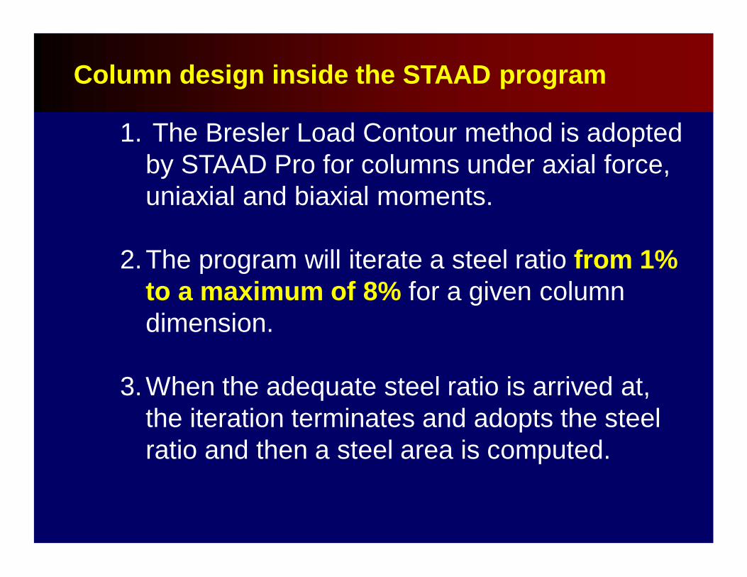
Column design inside the STAAD program
1. The Bresler Load Contour method is adopted by STAAD Pro for columns under axial force, uniaxial and biaxial moments.
2.The program will iterate a steel ratio from 1% to a maximum of 8% for a given column dimension.
3.When the adequate steel ratio is arrived at, the iteration terminates and adopts the steel ratio and then a steel area is computed.
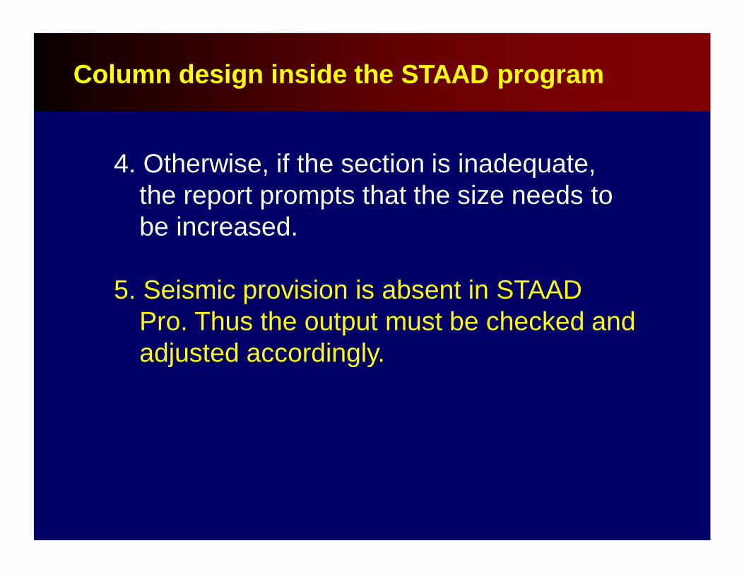
4. Otherwise, if the section is inadequate, the report prompts that the size needs to be increased.
5. Seismic provision is absent in STAAD Pro. Thus the output must be checked and adjusted accordingly.
Column design inside the STAAD program
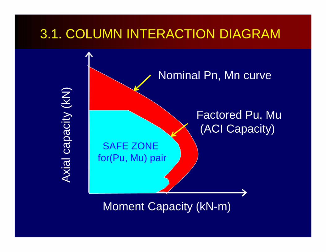
Nominal Pn, Mn curve
Factored Pu, Mu(ACI Capacity)
Axi
al c
apac
ity (k
N)
Moment Capacity (kN-m)
SAFE ZONE for(Pu, Mu) pair
3.1. COLUMN INTERACTION DIAGRAM
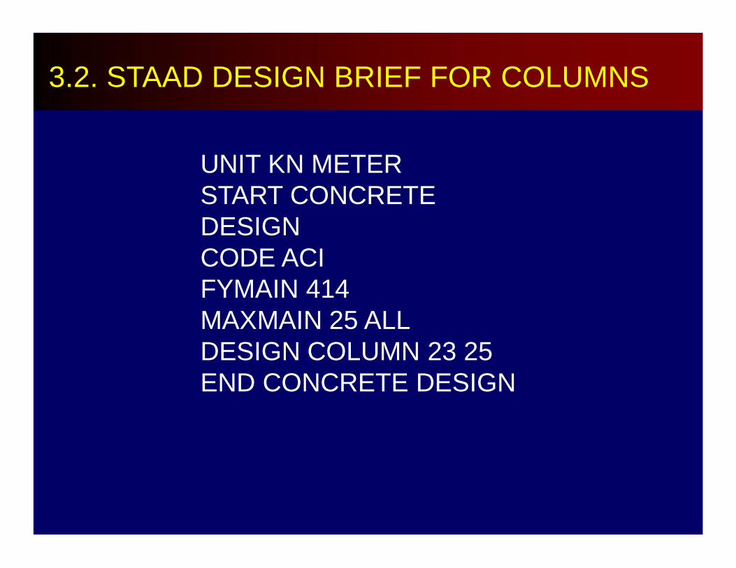
UNIT KN METERSTART CONCRETE DESIGNCODE ACI FYMAIN 414MAXMAIN 25 ALLDESIGN COLUMN 23 25END CONCRETE DESIGN
3.2. STAAD DESIGN BRIEF FOR COLUMNS
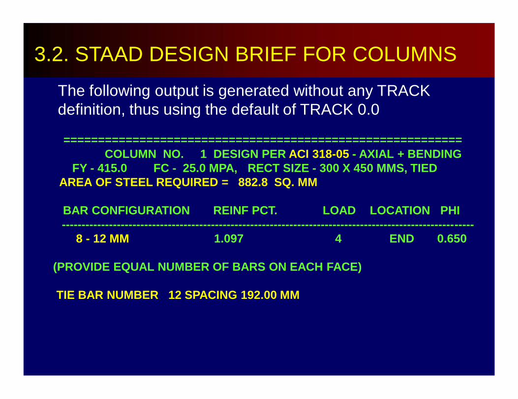
The following output is generated without any TRACK definition, thus using the default of TRACK 0.0
==========================================================COLUMN NO. 1 DESIGN PER ACI 318-05 - AXIAL + BENDING
FY - 415.0 FC - 25.0 MPA, RECT SIZE - 300 X 450 MMS, TIEDAREA OF STEEL REQUIRED = 882.8 SQ. MM
BAR CONFIGURATION REINF PCT. LOAD LOCATION PHI---------------------------------------------------------------------------------------------------------
8 - 12 MM 1.097 4 END 0.650
(PROVIDE EQUAL NUMBER OF BARS ON EACH FACE)
TIE BAR NUMBER 12 SPACING 192.00 MM
3.2. STAAD DESIGN BRIEF FOR COLUMNS

3.4. SEISMIC REQUIREMENTS FOR COLUMN
1. Longitudinal Reinforcements (NSCP 2010, 421.6.3.1)
• The reinforcement ratio g shall not be less than 0.01 and shall not exceed 0.06.
• The STAAD allows up to a maximum of 8%. Therefore, should the design be adequate with a steel ratio more than 6%, the section size shall be increased in order to satisfy a steel ratio of less than or equal to 6%.
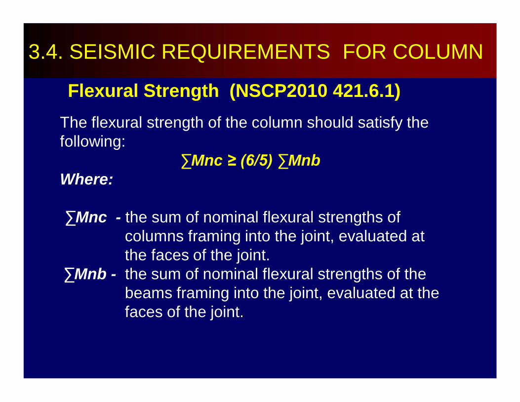
Flexural Strength (NSCP2010 421.6.1)The flexural strength of the column should satisfy the following:
∑Mnc ≥ (6/5) ∑MnbWhere:
∑Mnc - the sum of nominal flexural strengths of columns framing into the joint, evaluated at the faces of the joint.
∑Mnb - the sum of nominal flexural strengths of the beams framing into the joint, evaluated at the faces of the joint.
3.4. SEISMIC REQUIREMENTS FOR COLUMN

Mncbot
Mnctop
MnbrightMnbleft
(Mnctop + Mncbot) ≥ (6/5) (Mnbtop + Mnbbot)
sum of column moment capacity must be 20% higher than the sum of the beam moment capacity
3.4. SEISMIC REQUIREMENTS FOR COLUMN
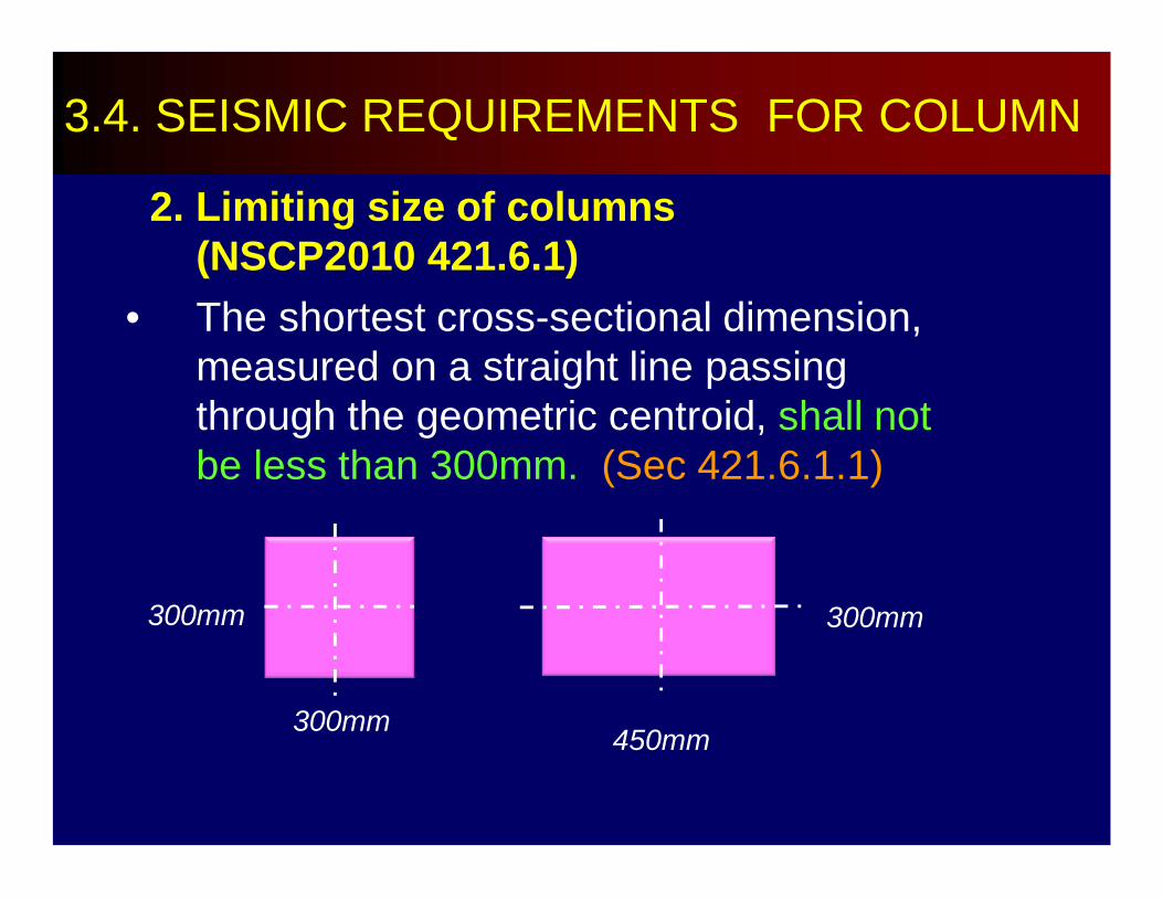
2. Limiting size of columns(NSCP2010 421.6.1)
• The shortest cross-sectional dimension, measured on a straight line passing through the geometric centroid, shall not be less than 300mm. (Sec 421.6.1.1)
3.4. SEISMIC REQUIREMENTS FOR COLUMN
300mm
300mm
300mm
450mm
hx > 0.4bx
bx
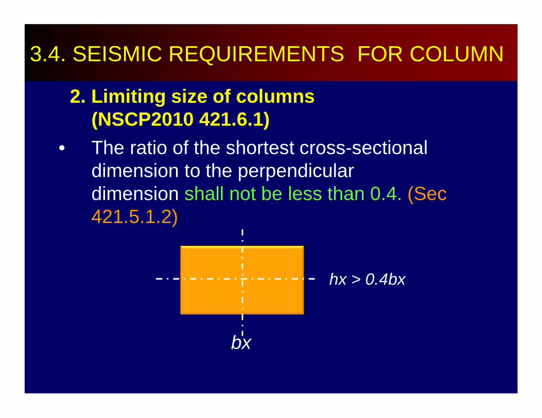
2. Limiting size of columns(NSCP2010 421.6.1)
• The ratio of the shortest cross-sectional dimension to the perpendicular dimension shall not be less than 0.4. (Sec 421.5.1.2)
3.4. SEISMIC REQUIREMENTS FOR COLUMN
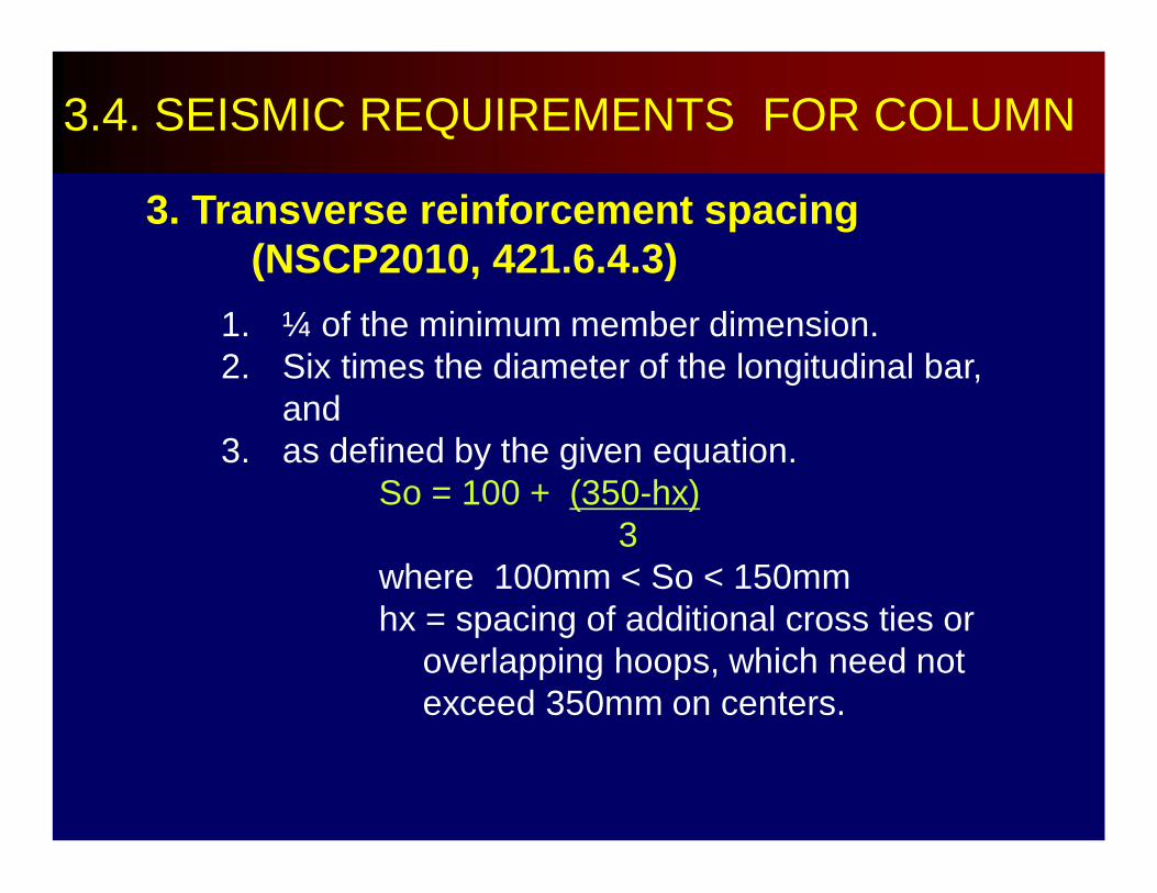
3. Transverse reinforcement spacing (NSCP2010, 421.6.4.3)
1. ¼ of the minimum member dimension.2. Six times the diameter of the longitudinal bar,
and 3. as defined by the given equation.
So = 100 + (350-hx)3
where 100mm < So < 150mmhx = spacing of additional cross ties or
overlapping hoops, which need not exceed 350mm on centers.
3.4. SEISMIC REQUIREMENTS FOR COLUMN
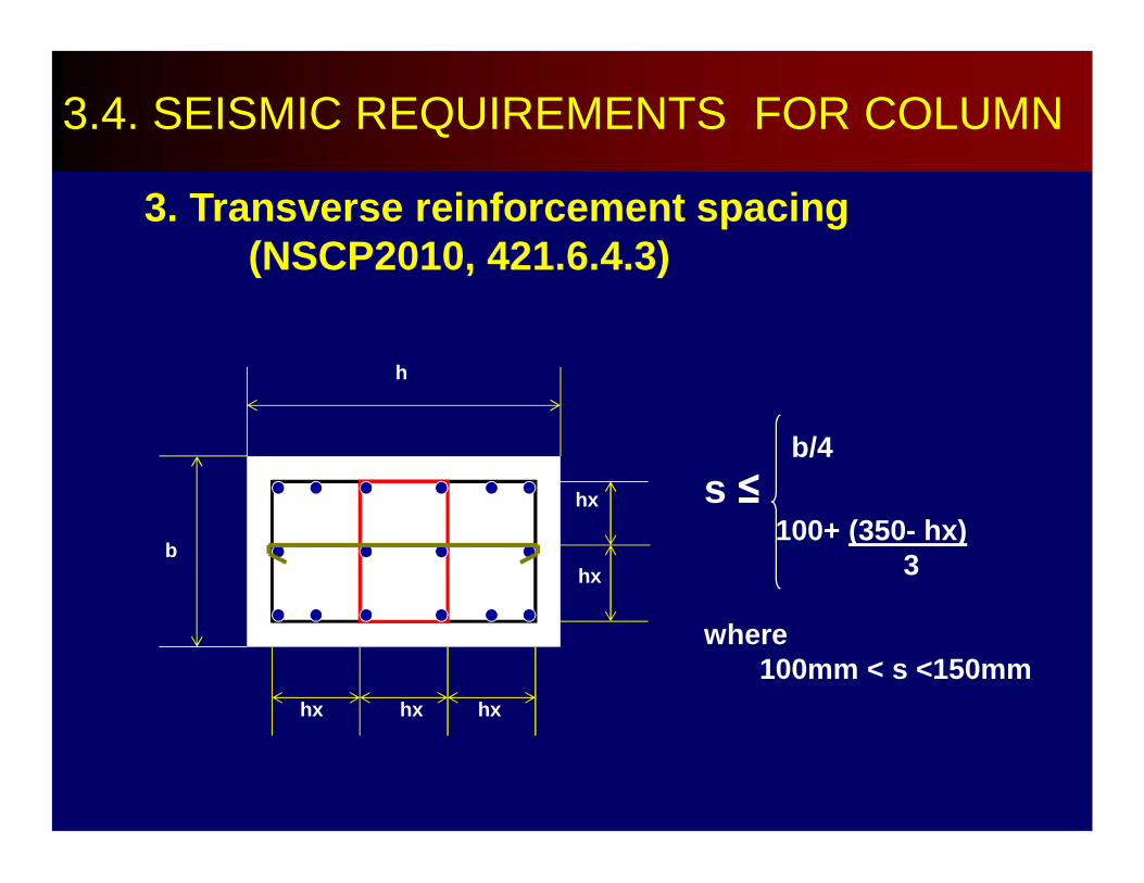
b
hx hx hx
hx
hx
h
b/4s ≤
100+ (350- hx)3
where 100mm < s <150mm
3. Transverse reinforcement spacing (NSCP2010, 421.6.4.3)
3.4. SEISMIC REQUIREMENTS FOR COLUMN
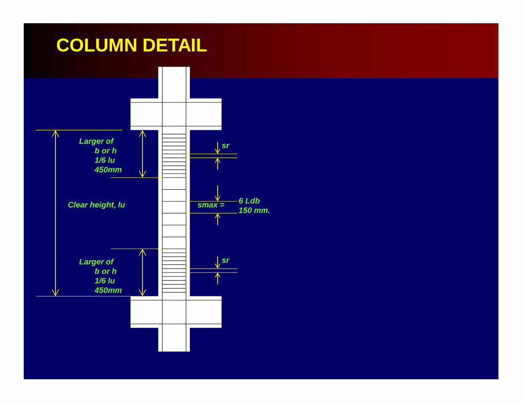
The transverse reinforcements shall be provided over a length, lo, from each joint face . The length, lo, shall not be less than the largest of:
1. The depth of the member at the joint face or where the flexural yielding is likely to occur.
2. One-sixth of the clear span of the member3. 450 mm.
3. Transverse reinforcement spacing (NSCP2010, 421.6.4.3)
3.4. SEISMIC REQUIREMENTS FOR COLUMN
Where transverse reinforcements are not required throughout the full length of the column, the hoops of the remainder of the column length shall be spaced at the smaller of :
a) 6 times the diameter of the longitudinal bars.
b) 150mm
3. Transverse reinforcement spacing (NSCP2010, 421.6.4.3)
3.4. SEISMIC REQUIREMENTS FOR COLUMN
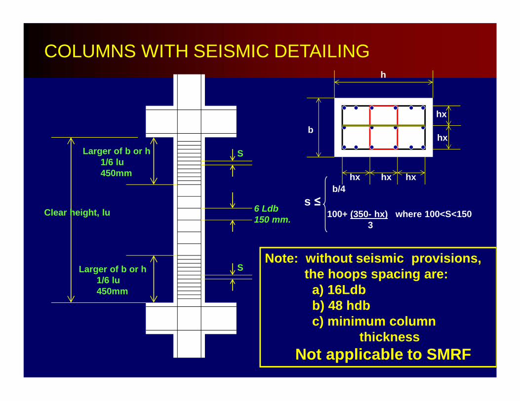
COLUMNS WITH SEISMIC DETAILING
S
S
Clear height, lu
Larger of b or h1/6 lu450mm
6 Ldb150 mm.
b
hx hx hx
hx
hx
h
b/4s ≤
100+ (350- hx) where 100<S<1503
Larger of b or h1/6 lu450mm
Note: without seismic provisions, the hoops spacing are:
a) 16Ldbb) 48 hdbc) minimum column
thicknessNot applicable to SMRF
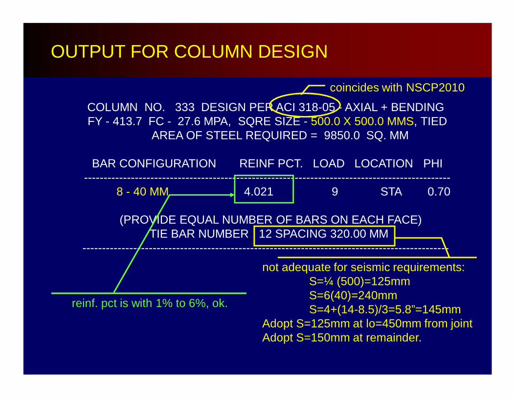
OUTPUT FOR COLUMN DESIGN
COLUMN NO. 333 DESIGN PER ACI 318-05 - AXIAL + BENDINGFY - 413.7 FC - 27.6 MPA, SQRE SIZE - 500.0 X 500.0 MMS, TIED
AREA OF STEEL REQUIRED = 9850.0 SQ. MM
BAR CONFIGURATION REINF PCT. LOAD LOCATION PHI----------------------------------------------------------------------------------------------
8 - 40 MM 4.021 9 STA 0.70
(PROVIDE EQUAL NUMBER OF BARS ON EACH FACE)TIE BAR NUMBER 12 SPACING 320.00 MM
----------------------------------------------------------------------------------------------
coincides with NSCP2010
reinf. pct is with 1% to 6%, ok.
not adequate for seismic requirements:S=¼ (500)=125mmS=6(40)=240mmS=4+(14-8.5)/3=5.8”=145mm
Adopt S=125mm at lo=450mm from jointAdopt S=150mm at remainder.
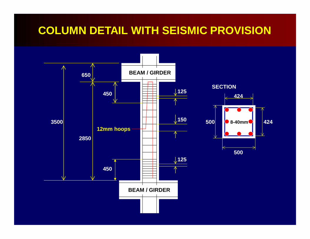
125
450
450
2850
650
3500
125
150 500
500
424
424
8-40mm12mm hoops
COLUMN DETAIL WITH SEISMIC PROVISION
BEAM / GIRDER
BEAM / GIRDER
SECTION
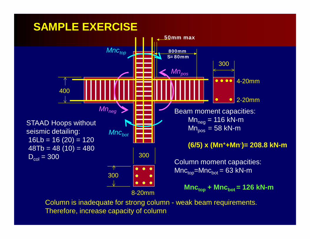
SAMPLE EXERCISE
800mm S=80mm
50mm max
300
2-20mm
4-20mm
300
8-20mm
400
300
STAAD Hoops without seismic detailing:16Lb = 16 (20) = 12048Tb = 48 (10) = 480Dcol = 300
Beam moment capacities:Mnneg = 116 kN-mMnpos = 58 kN-m
(6/5) x (Mn++Mn-)= 208.8 kN-m
Column moment capacities:Mnctop=Mncbot = 63 kN-m
Mnctop + Mncbot = 126 kN-m
Column is inadequate for strong column - weak beam requirements. Therefore, increase capacity of column
Mnctop
Mncbot
Mnneg
Mnpos
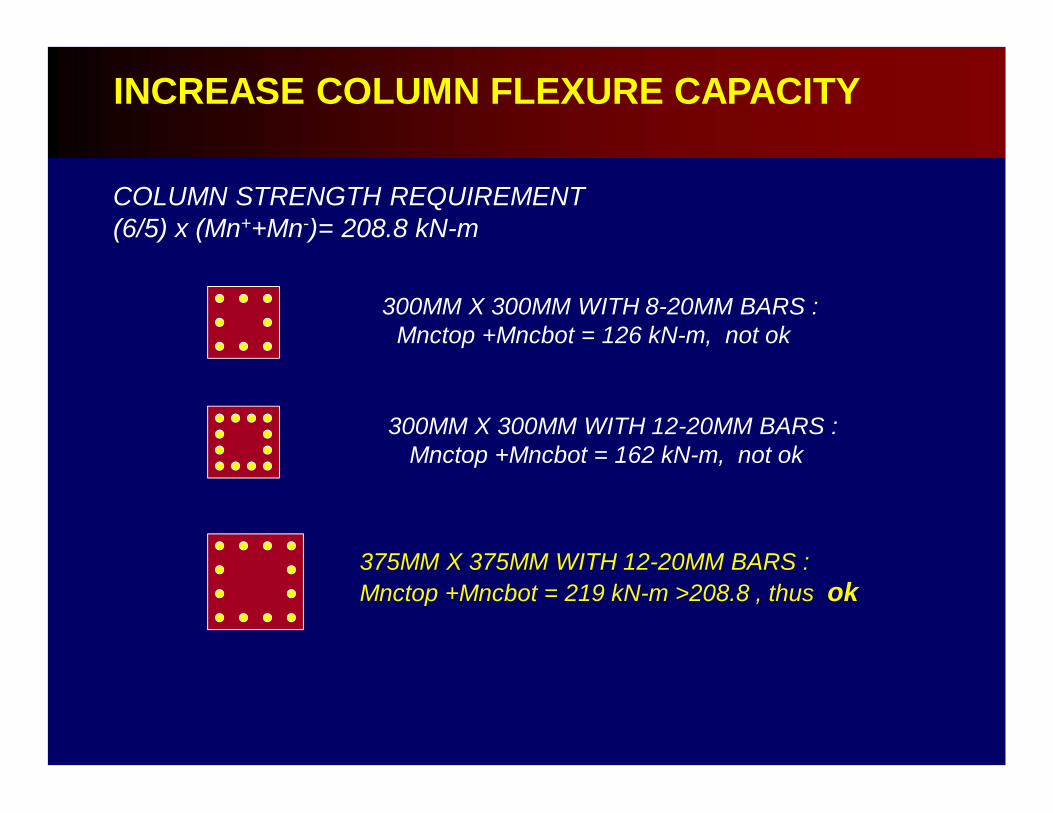
INCREASE COLUMN FLEXURE CAPACITY
COLUMN STRENGTH REQUIREMENT(6/5) x (Mn++Mn-)= 208.8 kN-m
300MM X 300MM WITH 8-20MM BARS :Mnctop +Mncbot = 126 kN-m, not ok
300MM X 300MM WITH 12-20MM BARS :Mnctop +Mncbot = 162 kN-m, not ok
375MM X 375MM WITH 12-20MM BARS :Mnctop +Mncbot = 219 kN-m >208.8 , thus ok
sr
sr
Clear height, lu
Larger of b or h1/6 lu450mm
Larger of b or h1/6 lu450mm
6 Ldb150 mm.
smax =
COLUMN DETAIL
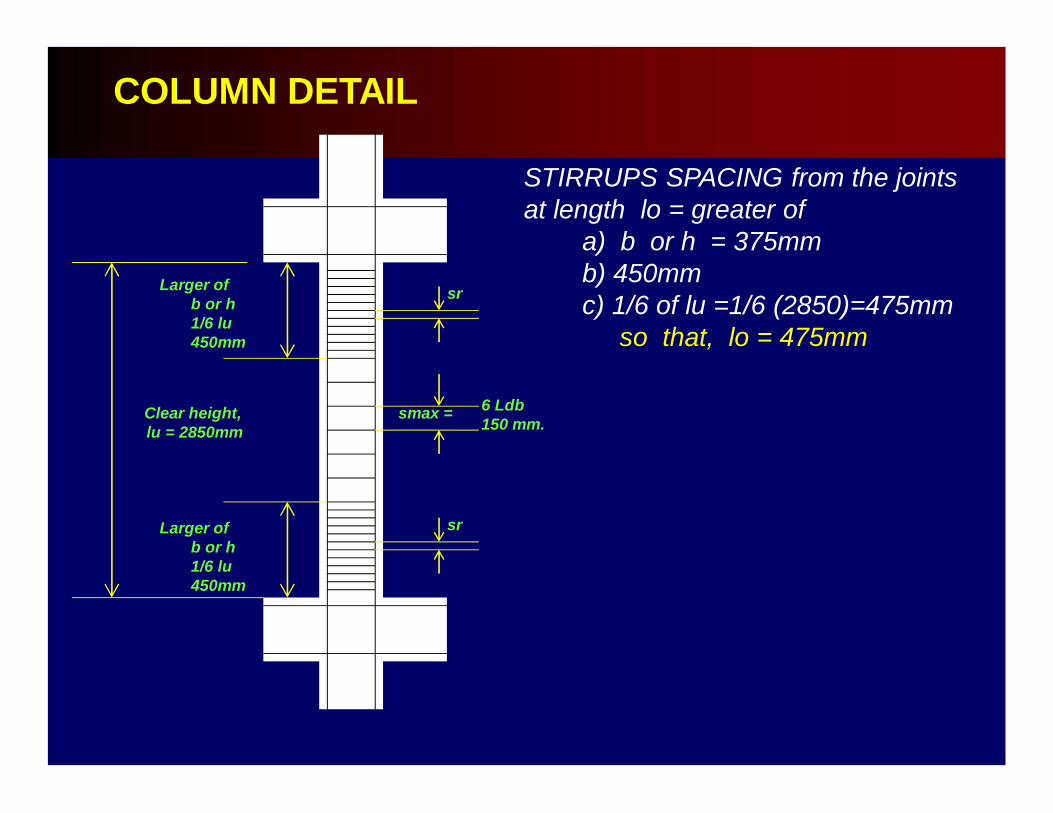
STIRRUPS SPACING from the jointsat length lo = greater of
a) b or h = 375mmb) 450mm c) 1/6 of lu =1/6 (2850)=475mm
so that, lo = 475mm
COLUMN DETAIL
sr
sr
Clear height, lu = 2850mm
Larger of b or h1/6 lu450mm
Larger of b or h1/6 lu450mm
6 Ldb150 mm.
smax =

STIRRUPS SPACING from the jointsat length lo = greater of
a) b or h = 375mmb) 450mm c) 1/6 of lu =1/6 (2850)=475mm
so that, lo = 450mm
COLUMN DETAIL
sr
sr
lu = 2850mm
lo = 475mm
6 Ldb150 mm.
smax =
lo = 475mm

COLUMN DETAIL
sr
sr
lu = 2850mm
lo = 475mm
lo = 475mm
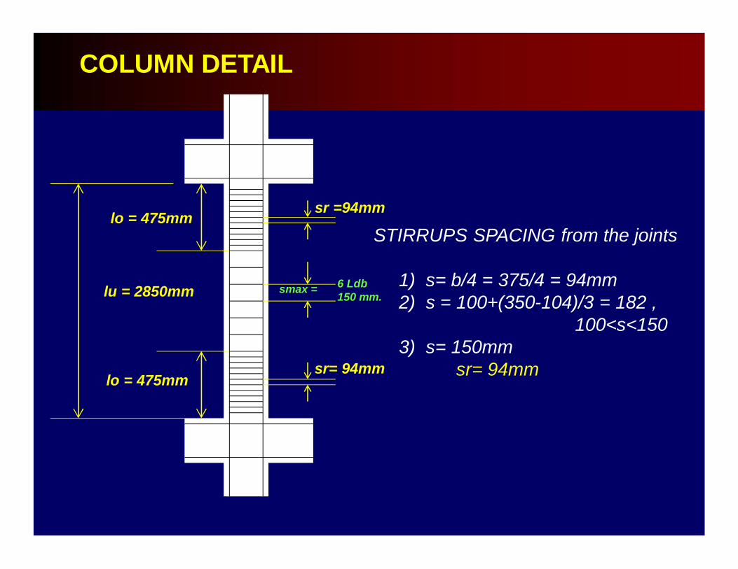
STIRRUPS SPACING from the joints
1) s= b/4 = 375/4 = 94mm2) s = 100+(350-104)/3 = 182,
100<s<1503) s= 150mm
sr= 94mm
COLUMN DETAIL
sr =94mm
sr= 94mm
lo = 475mm
lo = 475mm
STIRRUPS SPACING from the joints
1) s= b/4 = 375/4 = 94mm2) s = 100+(350-104)/3 = 182 ,
100<s<1503) s= 150mm
sr= 94mm
lu = 2850mm 6 Ldb150 mm.
smax =
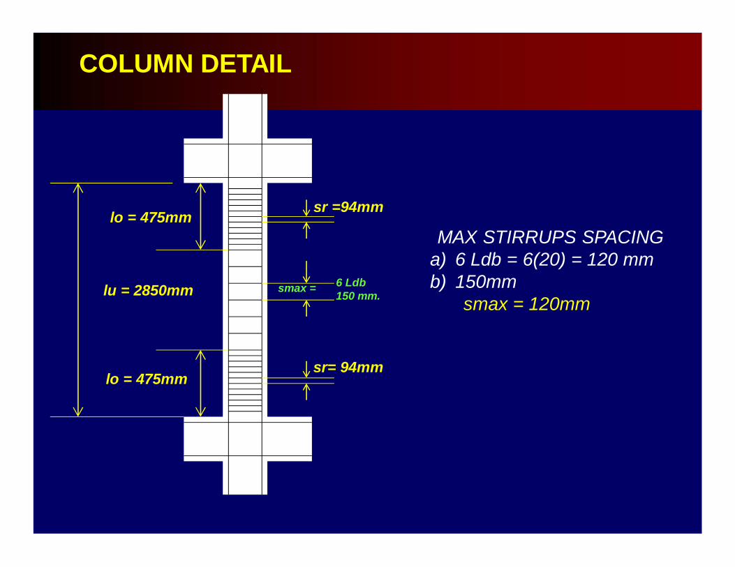
MAX STIRRUPS SPACING a) 6 Ldb = 6(20) = 120 mmb) 150mm
smax = 120mm
COLUMN DETAIL
sr =94mm
sr= 94mm
lo = 475mm
lo = 475mm
lu = 2850mm 6 Ldb150 mm.
smax =

MAX STIRRUPS SPACING a) 6 Ldb = 6(20) = 120 mmb) 150mm
smax = 120mm
COLUMN DETAIL
sr =94mm
sr= 94mm
lo = 475mm
lo = 475mm
lu = 2850mm
smax = 120mm
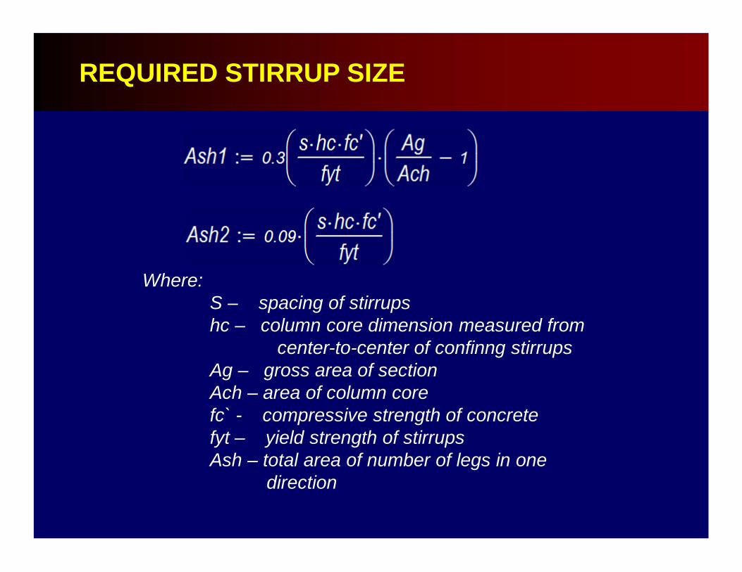
REQUIRED STIRRUP SIZE
Where:S – spacing of stirrupshc – column core dimension measured from
center-to-center of confinng stirrupsAg – gross area of sectionAch – area of column corefc` - compressive strength of concretefyt – yield strength of stirrupsAsh – total area of number of legs in one
direction
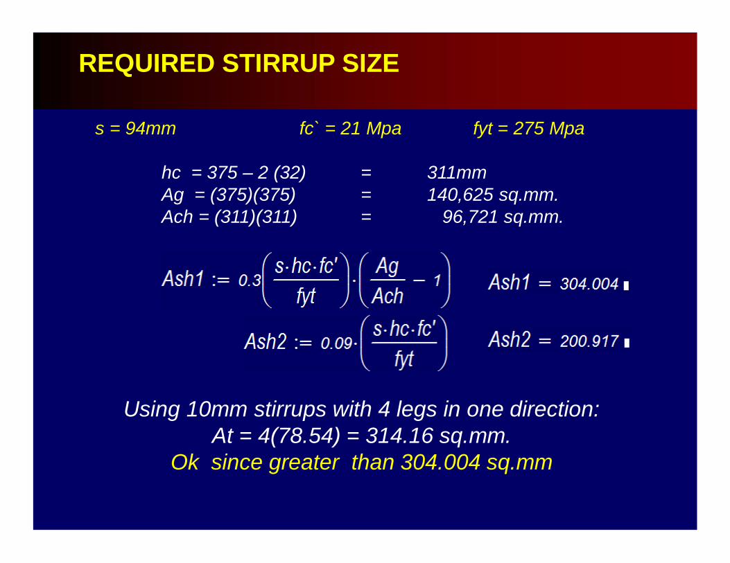
s = 94mm fc` = 21 Mpa fyt = 275 Mpa
hc = 375 – 2 (32) = 311mmAg = (375)(375) = 140,625 sq.mm.Ach = (311)(311) = 96,721 sq.mm.
REQUIRED STIRRUP SIZE
Using 10mm stirrups with 4 legs in one direction:At = 4(78.54) = 314.16 sq.mm.
Ok since greater than 304.004 sq.mm
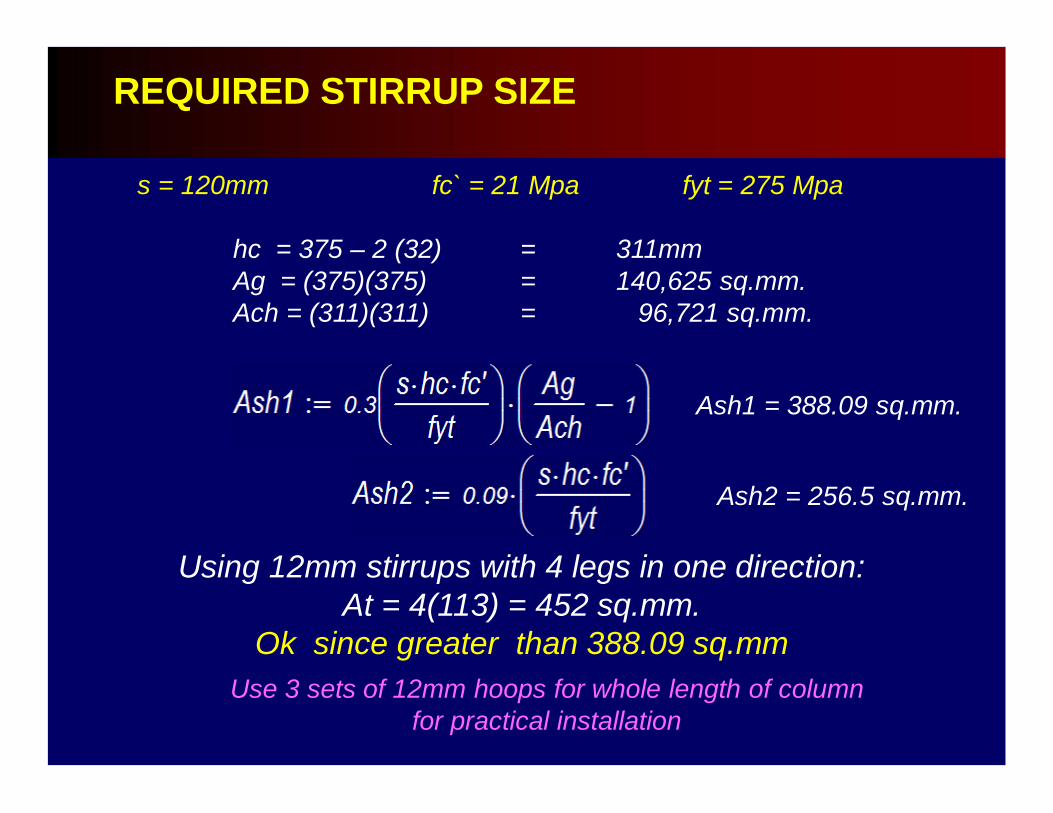
s = 120mm fc` = 21 Mpa fyt = 275 Mpa
hc = 375 – 2 (32) = 311mmAg = (375)(375) = 140,625 sq.mm.Ach = (311)(311) = 96,721 sq.mm.
REQUIRED STIRRUP SIZE
Using 12mm stirrups with 4 legs in one direction:At = 4(113) = 452 sq.mm.
Ok since greater than 388.09 sq.mm
Ash1 = 388.09 sq.mm.
Ash2 = 256.5 sq.mm.
Use 3 sets of 12mm hoops for whole length of column for practical installation
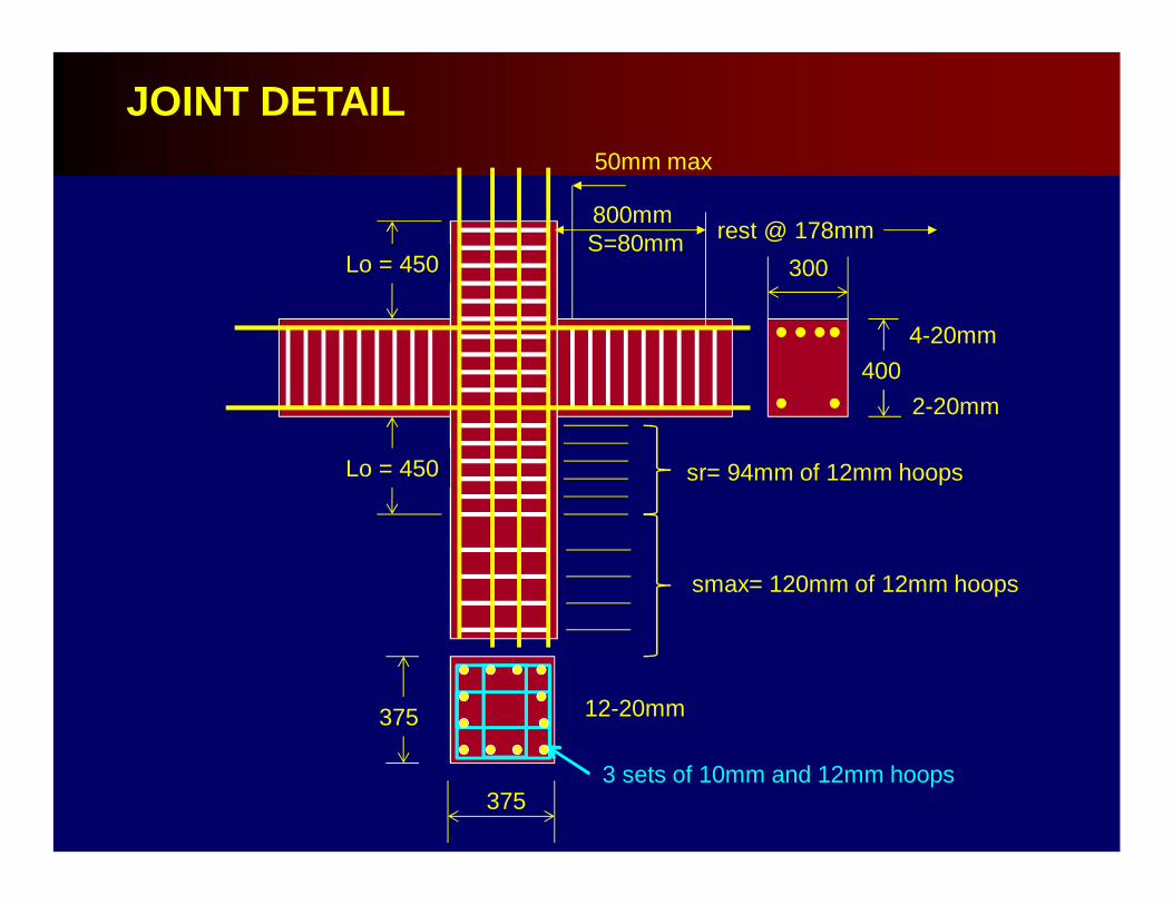
800mm S=80mm
50mm max
400
300
Lo = 450
Lo = 450
4-20mm
2-20mm
smax= 120mm of 12mm hoops
sr= 94mm of 12mm hoops
375
375
12-20mm
3 sets of 10mm and 12mm hoops
JOINT DETAIL
rest @ 178mm
DESIGN GUIDELINES
1.Check design seismic design requirements.
DESIGN GUIDELINES
2. STAAD Pro output does not, as of yet, have provisions for seismic detailing requirement.
Therefore, the output should not be used as the final detail without modification when designing for SMRF.
3. The seismic detailing should start first on the beam: supports and midspanrequirements must be satisfied before going to the columns.
DESIGN GUIDELINES
4. Satisfy strong column –weak beam requirement.
DESIGN GUIDELINES
5. Finally, once the seismic requirements are satisfied, then and only then the detailed drawings are carried out.
DESIGN GUIDELINES

LET’S GO TO STAAD PRO