rci-8510 installation service manual eng rev1.0 -...
TRANSCRIPT

www.trimble.com/liftingsolutions
RCI-8510 Load Moment Indicator SINGLE / TWIN WINCH TELESCOPIC BOOM CRANE Installation and Service Manual
ENGLISH
RCI-8510_AT422T_ENG_rev1.0

RCI-8510 INSTALLATION AND SERVICE
TABLE OF CONTENTS 2
Table of Contents
TABLE OF CONTENTS ........................................................................................................ 2
1. OVERVIEW ..................................................................................................................... 7
1.1. ABOUT THIS MANUAL ................................................................................................... 7 1.2. WHO SHOULD READ THIS MANUAL ............................................................................... 7 1.3. HOW TO PROVIDE FEEDBACK TO TRIMBLE LIFTING SOLUTIONS ....................................... 7 1.4. HOW THIS MANUAL IS UPDATED ................................................................................... 7 1.5. HOW TO CONTACT TLS ............................................................................................... 7 1.6. GLOSSARY .................................................................................................................. 9
2. SAFETY NOTIFICATIONS ........................................................................................... 10
3. GENERAL DESCRIPTION ........................................................................................... 11
3.1. OVERVIEW ................................................................................................................ 11 3.2. CAPABILITIES ............................................................................................................ 11 3.3. SYSTEM COMPONENTS .............................................................................................. 12 3.4. DISPLAY UNIT ........................................................................................................... 13
4. INSTALLATION ............................................................................................................ 18
4.1. OVERVIEW ................................................................................................................ 18 4.2. BEFORE YOU BEGIN .................................................................................................. 18 4.3. INSTALLATION PROCEDURE ........................................................................................ 18 4.4. POWER SUPPLY ........................................................................................................ 19 4.5. SUPPLY OVER-VOLTAGE PROTECTION ........................................................................ 19 4.6. EXCITATION VOLTAGE OUTPUTS ................................................................................. 19 4.7. RCI-8510 DISPLAY UNIT ........................................................................................... 20 4.8. CABLE CONNECTIONS ................................................................................................ 20 4.9. TELESCOPIC BOOM RECOIL DRUM .............................................................................. 20
4.9.1. Mounting Location ............................................................................................... 21 4.9.2. Installation ........................................................................................................... 22 4.9.3. Recoil Drum Final Checks .................................................................................. 23
4.10. ANTI-TWO-BLOCK SYSTEM (ATB) ............................................................................ 23 4.10.1. Installation ......................................................................................................... 24 4.10.2. ATB Switch Final Checks .................................................................................. 24
4.11. LUFFING RAM/BOOM LIFT CYLINDER PRESSURE TRANSDUCERS ................................. 25 4.11.1. Luff cylinder ....................................................................................................... 25 4.11.2. Pressure Transducer Final Checks ................................................................... 26
4.12. CABLING ................................................................................................................. 26 4.12.1. Cable Routing ................................................................................................... 26 4.12.2. Cable Reels ...................................................................................................... 27 4.12.3. Compression Glands ........................................................................................ 27 4.12.4. Earthing Requirements ..................................................................................... 27 4.12.5. Switch Box ........................................................................................................ 28
4.13. SNUBBER DIODES ON RELAYS AND SOLENOIDS ......................................................... 29
RCI-8510 INSTALLATION AND SERVICE
TABLE OF CONTENTS 3
4.14. PROXIMITY SWITCHES ............................................................................................. 29 4.15. DIGITAL INPUTS AND OUTPUTS ................................................................................. 31
4.15.1. Digital Inputs ..................................................................................................... 31 4.15.2. Digital Outputs .................................................................................................. 31 4.15.3. Identifying and Connecting Digital Inputs and Outputs ..................................... 32
4.16. ANALOG INPUTS ...................................................................................................... 33 4.16.1. Sensor Excitation .............................................................................................. 33 4.16.2. Identifying and Connecting Analog Sensor Inputs. ........................................... 33
5. CALIBRATION ............................................................................................................. 34
5.1. OVERVIEW ................................................................................................................ 34 5.2. SET LANGUAGE ......................................................................................................... 34 5.3. CHECK/SET DATE AND TIME ....................................................................................... 34 5.4. CHECK UNITS OF MEASUREMENT ............................................................................... 35 5.5. CRANE SERIAL NUMBER ............................................................................................ 35 5.6. SENSOR OVERVIEW ................................................................................................... 36 5.7. CALIBRATING BOOM ANGLE AND LENGTH .................................................................... 37
5.7.1. Accessing the Calibration Menu ......................................................................... 37 5.7.2. Calibrate Boom Angle ......................................................................................... 37 5.7.3. Calibrate Boom Length ....................................................................................... 40
6. TECHNICIAN/CALIBRATION MENU .......................................................................... 43
6.1. OVERVIEW ................................................................................................................ 43 6.2. TECHNICIAN ACCESS MENU DESCRIPTIONS ................................................................. 43
6.2.1. Sensor Setup ...................................................................................................... 43 6.2.2. Lift Thresholds .................................................................................................... 47 6.2.3. Select Parts of Line ............................................................................................. 47 6.2.4. Select Duty .......................................................................................................... 47 6.2.5. Data Logger Setup .............................................................................................. 48
6.3. CALIBRATION MENU ................................................................................................... 49 6.3.1. Accessing the Calibration Menu ......................................................................... 49 6.3.2. Calibration Menu ................................................................................................. 49
7. DATA LOGGER ........................................................................................................... 50
8. SOFTWARE UPDATES ............................................................................................... 51
9. TROUBLESHOOTING ................................................................................................. 52
9.1. OVERVIEW ................................................................................................................ 52 9.2. ANALOG SENSOR ERRORS ......................................................................................... 55 9.3. DIGITAL INPUT/OUTPUT ERRORS ................................................................................ 56 9.4. DO NOT MODIFY THE CALIBRATION ............................................................................ 57 9.5. COMMON PROBLEMS ................................................................................................. 58 9.6. CONTACTING TLS ..................................................................................................... 62
10. SPECIFICATIONS ...................................................................................................... 63
10.1. DISPLAY UNIT ......................................................................................................... 63 10.2. CONTROLLER .......................................................................................................... 63 10.3. ENVIRONMENTAL ..................................................................................................... 63

RCI-8510 INSTALLATION AND SERVICE
TABLE OF CONTENTS 4
10.4. ELECTRICAL ............................................................................................................ 64 10.4.1. Power Supply .................................................................................................... 64 10.4.2. Analog Sensor Inputs ........................................................................................ 64 10.4.3. Fuses ................................................................................................................ 64 10.4.4. Digital Inputs ..................................................................................................... 64 10.4.5. Digital Outputs .................................................................................................. 65 10.4.6. Sensor Excitation .............................................................................................. 65 10.4.7. Serial I/O ........................................................................................................... 65 10.4.8. Electrical Interface ............................................................................................ 65 10.4.9. Microprocessor ................................................................................................. 65 10.4.10. Data Transfer .................................................................................................. 65
10.5. SUPERVISORY ......................................................................................................... 66 10.6. TIMEKEEPING .......................................................................................................... 66 10.7. DIAGNOSTICS .......................................................................................................... 66
REVISION HISTORY .......................................................................................................... 67
APPENDIX A: GENERAL ARRANGEMENT DRAWINGS .................................................. A
APPENDIX B: DUTY LISTING ............................................................................................ B
APPENDIX C: SOFTWARE CONFIGURATION .................................................................. C
APPENDIX D: COMPONENT DRAWINGS ......................................................................... D

RCI-8510 INSTALLATION AND SERVICE
LIST OF FIGURES 5
LIST OF FIGURES Figure 2: Typical Load Moment System for Mobile Telescopic Crane ................................ 12 Figure 5: Display Unit Example ........................................................................................... 13 Figure 6: Display Preferences Pop-Up ................................................................................ 14 Figure 7: Display Initial Boot Screen ................................................................................... 15 Figure 8: Duty Selection Pop-Up ......................................................................................... 16 Figure 9: Hoist Rope Parts of Line Selection Pop-Up ......................................................... 17 Figure 10: Example of A6 Crane Mode Screen ................................................................... 17 Figure 12: Extension Recoil Drums – 13 m, 26m and 35 m models ................................... 21 Figure 13: Recoil Drum Inclinometer Orientation ................................................................ 21 Figure 14: Pressure Transducer Samples ........................................................................... 25 Figure 19: Snubber Diode Installation ................................................................................. 29 Figure 21: Typical Slew Proximity Switch Installation ......................................................... 30 Figure 22: Proximity Switch Typical Installation Guidelines ................................................ 30 Figure 24: 0-5V Inclinometer and 4-20mA Inclinometer ...................................................... 38 Figure 25: Recoil Drum Inclinometer Adjustment ................................................................ 39 Figure 26: Recoil Drum Potentiometer Adjustment ............................................................. 41 Figure 28: Live View Analog Screen ................................................................................... 45 Figure 29: Live View Digital Screen .................................................................................... 46 Figure 32: A6 Screen ("Spanner" icon bottom left) .............................................................. 52 Figure 33: A3 Screen ("Spanner" icon bottom left) .............................................................. 52 Figure 34: Fault Summary Screen ...................................................................................... 53 Figure 35: LMI Diagnostics Screen ..................................................................................... 53 Figure 36: CANBus Diagnostic Screen ............................................................................... 55 Figure 37: Analog Live View ................................................................................................ 56 Figure 38: Digital Live View ................................................................................................. 56 Figure 39: Home Screen ..................................................................................................... 62

RCI-8510 INSTALLATION AND SERVICE
LIST OF TABLES 6
LIST OF TABLES Table 3: Typical Load Moment System Components for Mobile Telescopic Crane ............ 12 Table 6: Operator Display Functions A6 Display ................................................................. 14 Table 11: Diagnostic Error Codes ....................................................................................... 54 Table 12: Common Problems and Solutions ....................................................................... 58 Table 13: Critical Information to Supply to TLS ................................................................... 62

RCI-8510 INSTALLATION AND SERVICE
CHAPTER 1: OVERVIEW 7
1. Overview
1.1. About This Manual This service manual describes how to install and service the RCI-8510 LMI System Installed on the hydraulic telescopic cranes. Information relating specifically to the crane identified on the front cover is located in the following chapters:
• Appendix A: General Arrangement Drawings
• Appendix B: Duty Listing
• Appendix C: System Configuration Documentation
• Appendix D: Component Drawings Refer to the RCI-8510 Operator Manual for instructions to operate the RCI-8510 system.
1.2. Who Should Read This Manual This manual assumes that you are a trained and qualified TLS Channel Partner, with access to the necessary tools in order to perform the tasks described herein.
1.3. How to Provide Feedback to Trimble Lifting Solutions Trimble Lifting Solutions (TLS) welcomes your feedback on the accuracy and effectiveness of this document. Please send feedback to [email protected]. Please include the title of the manual and version (this information is located on the cover page) with your feedback.
1.4. How This Manual Is Updated TLS will issue new releases of this manual as new material becomes available. Refer to the Document Revision History at the end of this manual. Latest version is available on our website www.trimble.com/liftingsolutions.
1.5. How to Contact TLS Please contact TLS if you encounter problems or require advice. Contact details are located at the back page of this manual. Please ensure that you provide the information listed in 9.6 Contacting TLS.
RCI-8510 INSTALLATION AND SERVICE
CHAPTER 1: OVERVIEW 8
Notifications Included in Document The following notations may be used in this manual:
(Condition) A condition in parentheses means that the information following only relates to that instance. For example, if you see (Load moment) at the start of a task, it means that the task is only applicable to load moment systems.
DANGER
DANGER INDICATES AN IMMINENTLY HAZARDOUS SITUATION WHICH, IF NOT AVOIDED, WILL RESULT IN DEATH OR SERIOUS INJURY.
WARNING
WARNING INDICATES A POTENTIALLY HAZARDOUS SITUATION WHICH, IF NOT AVOIDED, COULD RESULT IN DEATH OR SERIOUS INJURY.
CAUTION
CAUTION INDICATES A POTENTIALLY HAZARDOUS SITUATION WHICH, IF NOT AVOIDED, COULD RESULT IN MINOR OR MODERATE INJURY.
IMPORTANT
IMPORTANT INDICATES A SITUATION WHICH, IF NOT AVOIDED, COULD RESULT IN DAMAGE TO EQUIPMENT.
NOTE
NOTE INDICATES INFORMATION WHICH IF FOLLOWED CAN FACILITATE SYSTEM INSTALLATION, CALIBRATION OR UNDERSTANDING.

RCI-8510 INSTALLATION AND SERVICE
CHAPTER 1: OVERVIEW 9
1.6. Glossary Abbreviations used in this manual are listed below.
ADC Analog To Digital Convertor
ATB Anti-Two-Block
AUX Auxiliary lifting point, typically a lower capacity hoist
DGND Digital Ground
DI/O Digital Input/Output
DIN Deutsches Institut für Normung – EN 50022
EMC Electromagnetic Compatibility
EMI Electromagnetic Interference
GA General Assembly drawing showing system components and wiring, aka as-built drawing
I/O Input/Output
LMI Load Moment Indicator
NC Normally Closed (Electrical)
NO Normally Opened (Electrical)
PIN Personal Identification Number
RC Rated Capacity
RCI Rated Capacity Indicator
RCL Rated Capacity Limiter
VEX Voltage Excitation
WA Work Authority. Used as a specific Software Job Number reference. Normally a 6 digit number and may be prefixed WA.
RCI-8510 INSTALLATION AND SERVICE
CHAPTER 2: SAFETY NOTIFICATIONS 10
2. Safety Notifications
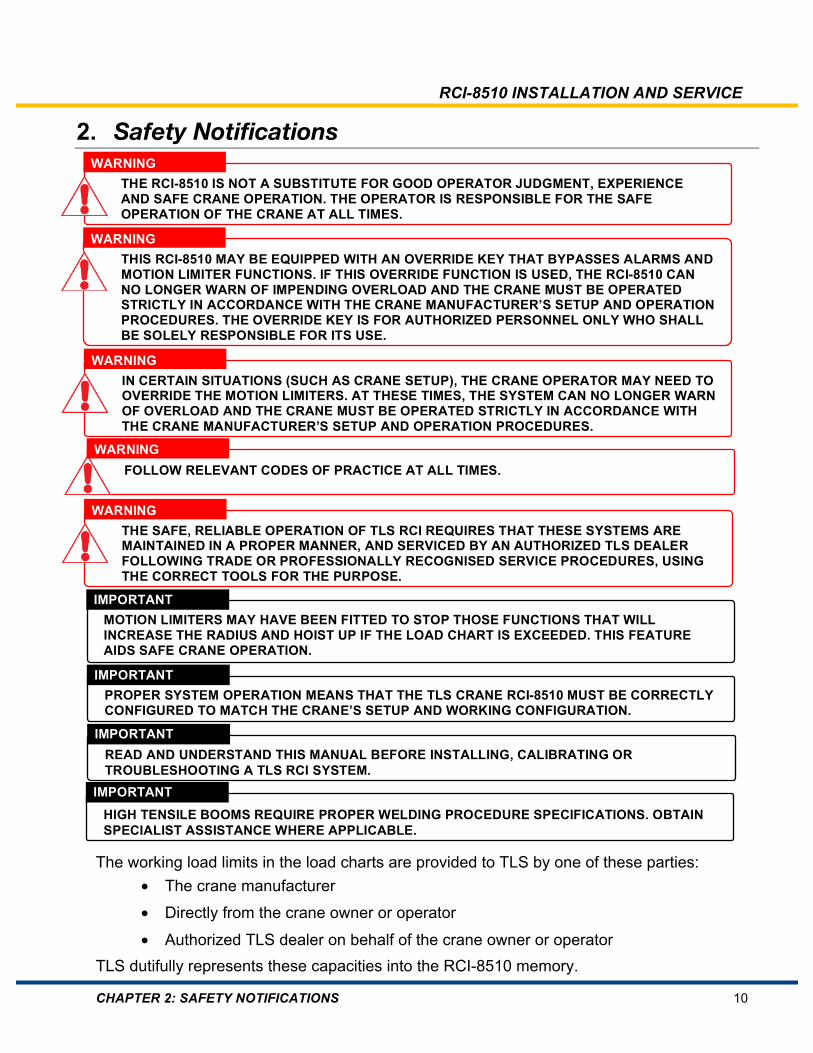
The working load limits in the load charts are provided to TLS by one of these parties: • The crane manufacturer
• Directly from the crane owner or operator
• Authorized TLS dealer on behalf of the crane owner or operator TLS dutifully represents these capacities into the RCI-8510 memory.
WARNING THE RCI-8510 IS NOT A SUBSTITUTE FOR GOOD OPERATOR JUDGMENT, EXPERIENCE AND SAFE CRANE OPERATION. THE OPERATOR IS RESPONSIBLE FOR THE SAFE OPERATION OF THE CRANE AT ALL TIMES.
WARNING THIS RCI-8510 MAY BE EQUIPPED WITH AN OVERRIDE KEY THAT BYPASSES ALARMS AND MOTION LIMITER FUNCTIONS. IF THIS OVERRIDE FUNCTION IS USED, THE RCI-8510 CAN NO LONGER WARN OF IMPENDING OVERLOAD AND THE CRANE MUST BE OPERATED STRICTLY IN ACCORDANCE WITH THE CRANE MANUFACTURER’S SETUP AND OPERATION PROCEDURES. THE OVERRIDE KEY IS FOR AUTHORIZED PERSONNEL ONLY WHO SHALL BE SOLELY RESPONSIBLE FOR ITS USE.
WARNING IN CERTAIN SITUATIONS (SUCH AS CRANE SETUP), THE CRANE OPERATOR MAY NEED TO OVERRIDE THE MOTION LIMITERS. AT THESE TIMES, THE SYSTEM CAN NO LONGER WARN OF OVERLOAD AND THE CRANE MUST BE OPERATED STRICTLY IN ACCORDANCE WITH THE CRANE MANUFACTURER’S SETUP AND OPERATION PROCEDURES. WARNING FOLLOW RELEVANT CODES OF PRACTICE AT ALL TIMES.
WARNING THE SAFE, RELIABLE OPERATION OF TLS RCI REQUIRES THAT THESE SYSTEMS ARE MAINTAINED IN A PROPER MANNER, AND SERVICED BY AN AUTHORIZED TLS DEALER FOLLOWING TRADE OR PROFESSIONALLY RECOGNISED SERVICE PROCEDURES, USING THE CORRECT TOOLS FOR THE PURPOSE.
IMPORTANT HIGH TENSILE BOOMS REQUIRE PROPER WELDING PROCEDURE SPECIFICATIONS. OBTAIN SPECIALIST ASSISTANCE WHERE APPLICABLE.
IMPORTANT READ AND UNDERSTAND THIS MANUAL BEFORE INSTALLING, CALIBRATING OR TROUBLESHOOTING A TLS RCI SYSTEM.
IMPORTANT MOTION LIMITERS MAY HAVE BEEN FITTED TO STOP THOSE FUNCTIONS THAT WILL INCREASE THE RADIUS AND HOIST UP IF THE LOAD CHART IS EXCEEDED. THIS FEATURE AIDS SAFE CRANE OPERATION.
IMPORTANT PROPER SYSTEM OPERATION MEANS THAT THE TLS CRANE RCI-8510 MUST BE CORRECTLY CONFIGURED TO MATCH THE CRANE’S SETUP AND WORKING CONFIGURATION.

RCI-8510 INSTALLATION AND SERVICE
CHAPTER 3: GENERAL DESCRIPTION 11
3. General Description
3.1. Overview The TLS RCI-8510 System is a device that warns the crane operator of impending overload and over-hoist conditions that could cause injury, or damage to property or the crane. This system warns the operator of:
• Approach to overload and overload warning (typically 85% and 100%, with visual and audible alarms)
• Overload (typically 100%, with visual and audible alarms, and motion-cut outputs)
3.2. Capabilities The Operator Screen of the RCI-8510 displays:
• Rated Capacity (RC) (max load) with % bar graph
• Total lifted load
• Radius
• Boom angle
• Duty selection
• Number of hoist rope parts of line
• Error reporting
• Date and time
• Wind Speed
Visual and audible alarms occur when the crane approaches or exceeds overload conditions. Calibration and fault-finding tools for service personnel are built-in to the system. For load moment systems, luffing ram pressures or boom luffing forces are used to calculate the total load on the boom. This means that for twin-winch systems that do not use a winch select input, the RCI-8510 calculates the RC based on which hoist rope the operator has selected (main or aux). In addition the total load on the boom is displayed rather than individual winch loads.

RCI-8510 INSTALLATION AND SERVICE
CHAPTER 3: GENERAL DESCRIPTION 12
3.3. System Components Telescopic cranes use the hydraulic luffing ram piston and rod pressure differential to calculate the load suspended on the various lifting points. Because the pressures are only an indication of the force required to luff the boom it is important to correctly identify which lifting point is being used by proper duty selection in order to correctly calculate the load on the hook.
Figure 1: Typical Load Moment System for Mobile Telescopic Crane
Table 1: Typical Load Moment System Components for Mobile Telescopic Crane Item Description
1 RCI-8510 Display Unit
2 Length and angle recoil drum
3 Piston pressure transducer(s)
4 Rod pressure transducer(s)
5 Anti-two-block switch and weight
6 RCI-8510 Controller
7 Slew proximity switch/slew encoder

RCI-8510 INSTALLATION AND SERVICE
CHAPTER 3: GENERAL DESCRIPTION 13
3.4. Display Unit Further information for RCI-8510 system operation can be found in the RCI-8510 Operator Manual.
Figure 2: Display Unit Example
Navigation through various screens is accomplished primarily using the rotary knob and function keys. F1 through F11 are what is referred to as “soft keys”, meaning their function changes depending upon what screen is displayed. F12 is reserved for alarm mute functionality.
RCI-8510 INSTALLATION AND SERVICE
CHAPTER 3: GENERAL DESCRIPTION 14
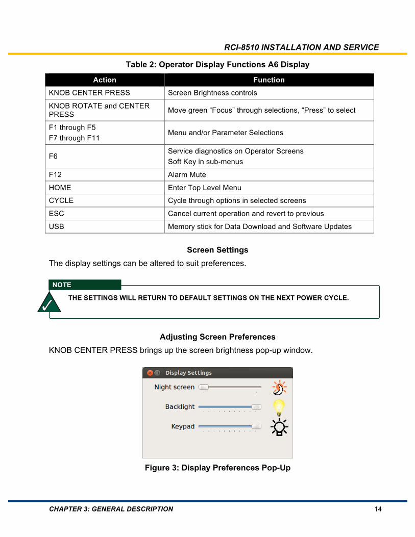
Table 2: Operator Display Functions A6 Display
Action Function
KNOB CENTER PRESS Screen Brightness controls
KNOB ROTATE and CENTER PRESS Move green “Focus” through selections, “Press” to select
F1 through F5 F7 through F11
Menu and/or Parameter Selections
F6 Service diagnostics on Operator Screens Soft Key in sub-menus
F12 Alarm Mute
HOME Enter Top Level Menu
CYCLE Cycle through options in selected screens
ESC Cancel current operation and revert to previous
USB Memory stick for Data Download and Software Updates
Screen Settings The display settings can be altered to suit preferences.
Adjusting Screen Preferences KNOB CENTER PRESS brings up the screen brightness pop-up window.
Figure 3: Display Preferences Pop-Up
NOTE
THE SETTINGS WILL RETURN TO DEFAULT SETTINGS ON THE NEXT POWER CYCLE.

RCI-8510 INSTALLATION AND SERVICE
CHAPTER 3: GENERAL DESCRIPTION 15
Day/Night Mode Toggle Three consecutive KNOB CENTER PRESSES will toggle between day/night screen settings. This is especially useful where headlamps are required for daylight operation since turning on the headlamps may automatically toggle the system to “Night Screen” settings. Other settings may be accessed by Knob Rotation then KNOB CENTER PRESS. Note that settings will not be retained after a subsequent power cycle. This is necessary to prevent a minimum brightness setting being retained and thus being unreadable during daylight.
Crane Ignition On
Figure 4: Display Initial Boot Screen
When the ignition is first turned on the display will show the logo. The logo will remain during the system boot-up sequence. During the power-up stages the RCL system goes through a sequence of internal diagnostics and operator confirmations to assure appropriate system setup prior to crane operation. After the initial system boot-up sequence is finished, the system will then prompt the operator for Duty selection and number of Parts of Line.
RCI-8510 INSTALLATION AND SERVICE
CHAPTER 3: GENERAL DESCRIPTION 16
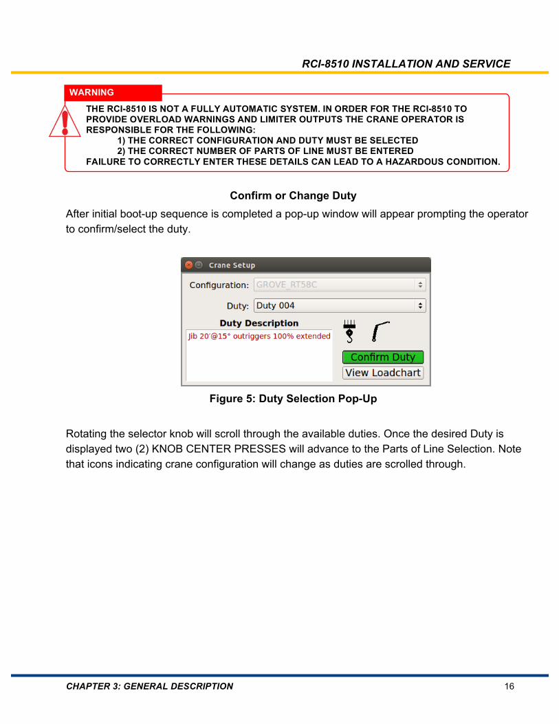
Confirm or Change Duty After initial boot-up sequence is completed a pop-up window will appear prompting the operator to confirm/select the duty.
Figure 5: Duty Selection Pop-Up
Rotating the selector knob will scroll through the available duties. Once the desired Duty is displayed two (2) KNOB CENTER PRESSES will advance to the Parts of Line Selection. Note that icons indicating crane configuration will change as duties are scrolled through.
WARNING
THE RCI-8510 IS NOT A FULLY AUTOMATIC SYSTEM. IN ORDER FOR THE RCI-8510 TO PROVIDE OVERLOAD WARNINGS AND LIMITER OUTPUTS THE CRANE OPERATOR IS RESPONSIBLE FOR THE FOLLOWING: 1) THE CORRECT CONFIGURATION AND DUTY MUST BE SELECTED 2) THE CORRECT NUMBER OF PARTS OF LINE MUST BE ENTERED FAILURE TO CORRECTLY ENTER THESE DETAILS CAN LEAD TO A HAZARDOUS CONDITION.
RCI-8510 INSTALLATION AND SERVICE
CHAPTER 3: GENERAL DESCRIPTION 17
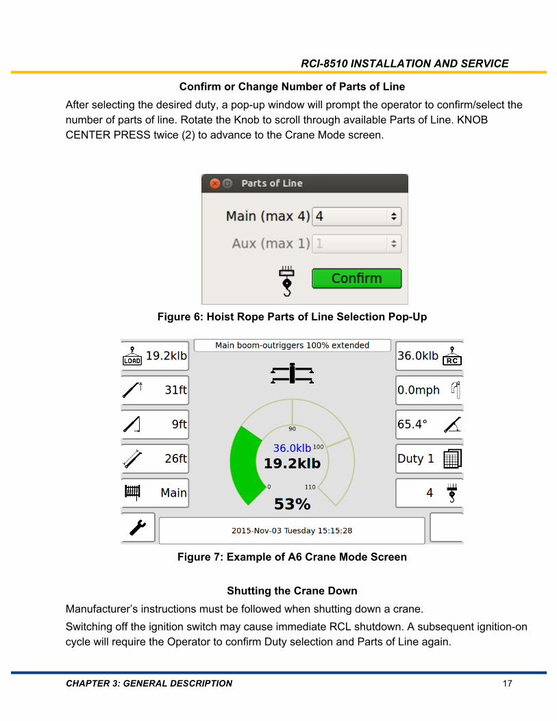
Confirm or Change Number of Parts of Line After selecting the desired duty, a pop-up window will prompt the operator to confirm/select the number of parts of line. Rotate the Knob to scroll through available Parts of Line. KNOB CENTER PRESS twice (2) to advance to the Crane Mode screen.
Figure 6: Hoist Rope Parts of Line Selection Pop-Up
Figure 7: Example of A6 Crane Mode Screen
Shutting the Crane Down Manufacturer’s instructions must be followed when shutting down a crane. Switching off the ignition switch may cause immediate RCL shutdown. A subsequent ignition-on cycle will require the Operator to confirm Duty selection and Parts of Line again.
RCI-8510 INSTALLATION AND SERVICE
CHAPTER 4: INSTALLATION 18
4. Installation
4.1. Overview This chapter provides a general description about how to install an RCI-8510 System. For detailed installation information you must also refer to the following appendices:
• Appendix A: General Arrangement Drawings
• Appendix B: Duty Listing
• Appendix C: System Configuration Documentation
• Appendix D: Component Drawings. Drawings of typical components supplied with RCI-8510
4.2. Before You Begin
4.3. Installation Procedure The RCI-8510 installation should follow a standard procedure. If this procedure is not followed then it may be difficult to achieve a successful calibration in a timely fashion. Typical Installation Procedure:
• Unpack system components and verify contents against packing list.
• Familiarize yourself with each system component and understand how it relates to the system GA drawing.
• Install Cabin components such as operator display and controller.
• Install Boom components such as inclinometers or recoil drums and load sensors.
• Install chassis components such as slew proxy switches or slew encoders.
• Connect load system limiter/function kickout outputs to crane controls.
• Perform sensor functional test.
• Perform sensor calibrations.
• Perform load calibrations, can be either tension-based or load moment.
WARNING THE INSTALLER IS RESPONSIBLE FOR ENSURING THAT THE INSTALLATION OF THE RCI-8510 COMPLIES WITH LOCAL STANDARDS AND REGULATIONS. A NON-COMPLIANT INSTALLATION MAY CAUSE HAZARDOUS CONDITIONS RESULTING IN INJURY OR DEATH.
WARNING A CERTIFIED CRANE OPERATOR MUST LOWER THE CRANE BOOM TO A SAFE AND CONVENIENT POSITION AND ENSURE THE CRANE IS IN A SAFE STATE BEFORE INSTALLATION CAN BEGIN. UNDER NO CIRCUMSTANCES SHOULD ANY CRANE OPERATION BE ATTEMPTED UNLESS BY A CERTIFIED CRANE OPERATOR.

RCI-8510 INSTALLATION AND SERVICE
CHAPTER 4: INSTALLATION 19
4.4. Power Supply The RCI-8510 is powered by a 10.5 VDC to 33 VDC supply. The power supply should be permanently connected to switched crane power. All inputs are transient protected. All internal power rails are current limited and short circuit protected using resettable fuses. No operator adjustments or settings are required internally.
4.5. Supply Over-Voltage Protection The RCI-8510 has high immunity to power supply over-voltage transients. However, in the case of extreme crane power system faults, the RCI-8510 has an internal protection mechanism which may cause a power supply fuse to blow. This will happen if the crane power supply exceeds 36 V for more than a few seconds (for example, if the crane battery is disconnected while being charged, or a heavy load). There are two fuses: an in-line fuse in the optional switch box, and an internal slow-blow fuse. Typically the switch box fuse will blow first. In the unlikely event that the internal fuse has blown the RCI-8510 controller cover will need to be removed to gain access to the internal 5x20 mm fuse.
Refer to Section 10.4.3 Fuses for fuse specifications.
4.6. Excitation Voltage Outputs Both the +15 V output and precision +5.00 V sensor excitation output can tolerate short circuits to ground without damage and not normally result in a blown fuse. Once the fault is removed the RCI-8510 system will return to normal operation after performing its start-up checks. If the +15 V output is shorted, the RCI-8510 system ceases to operate and will restart once the fault is cleared. If the +5.00 V sensor excitation is shorted, a system fault is triggered and the RCI-8510 system will go into motion cut/function kickout until the fault is removed.
IMPORTANT BOTH FUSES ARE SERVICEABLE ITEMS. DO NOT REPLACE FUSES WITH A HIGHER CURRENT RATING AS THIS MAY DAMAGE THE ELECTRONICS IN THE RCI-8510 IN THE EVENT OF FUTURE OVERVOLTAGE TRANSIENTS.
IMPORTANT ALWAYS INSTALL A 3 A FAST-ACTING FUSE IN-LINE WITH THE POWER SUPPLY POSITIVE. THIS AVOIDS HAVING TO OPEN THE RCI-8510 CONTROLLER TO ACCESS THE INTERNAL SLOW-BLOW FUSE. INSTALLING A FUSE OF HIGHER VALUE WILL VOID THE WARRANTY
RCI-8510 INSTALLATION AND SERVICE
CHAPTER 4: INSTALLATION 20
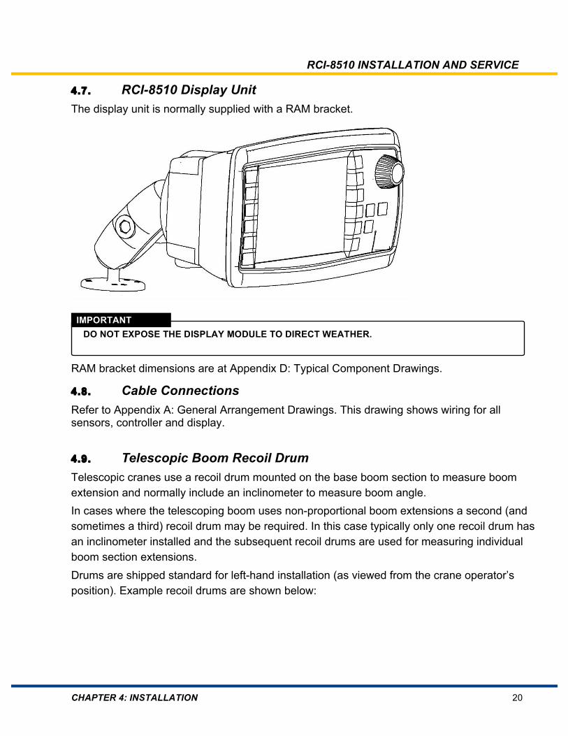
4.7. RCI-8510 Display Unit The display unit is normally supplied with a RAM bracket.
RAM bracket dimensions are at Appendix D: Typical Component Drawings.
4.8. Cable Connections Refer to Appendix A: General Arrangement Drawings. This drawing shows wiring for all sensors, controller and display.
4.9. Telescopic Boom Recoil Drum Telescopic cranes use a recoil drum mounted on the base boom section to measure boom extension and normally include an inclinometer to measure boom angle. In cases where the telescoping boom uses non-proportional boom extensions a second (and sometimes a third) recoil drum may be required. In this case typically only one recoil drum has an inclinometer installed and the subsequent recoil drums are used for measuring individual boom section extensions. Drums are shipped standard for left-hand installation (as viewed from the crane operator’s position). Example recoil drums are shown below:
IMPORTANT DO NOT EXPOSE THE DISPLAY MODULE TO DIRECT WEATHER.

RCI-8510 INSTALLATION AND SERVICE
CHAPTER 4: INSTALLATION 21
Figure 8: Extension Recoil Drums – 13 m, 26m and 35 m models
4.9.1. Mounting Location The preferred recoil drum mounting location is on the left-hand side of the boom which will position the payout cable entry at the top of the recoil drum. It is not necessary to change orientation of the inclinometer to monitor a full range of boom angle motion. Standard boom inclinometers have a range of ±90° or ±45°. If the recoil drum is mounted on the right-hand side of the boom the orientation of the boom inclinometer must be changed. To modify the position of the inclinometer for right-hand mount:
• Remove the recoil drum cover screws and remove the drum cover taking care not to let the cover hang on the cable connector. Unplug recoil drum cover cable harness if necessary.
• Remove the inclinometer fasteners and rotate the sensor 180°.
• Re-attach the sensor cable assembly to the terminal strip and re-install the drum cover, securely fastening the drum cover screws.
Figure 9: Recoil Drum Inclinometer Orientation
NOTE RIGHT HAND MOUNT INSTALL ANGLE SENSOR AS SHOWN WITH CABLE IN SAME DIRECTION AS PAYOUT CABLE. LEFT HAND MOUNT INSTALL ANGLE SENSOR WITH CABLE IN OPPOSITE DIRECTION.

RCI-8510 INSTALLATION AND SERVICE
CHAPTER 4: INSTALLATION 22
4.9.2. Installation Recoil Drum Installation Procedure:
• Begin with the boom fully retracted. Leave the cable stop on the cable until later.
• Check that the mounting face is flat, and parallel to the cable pay-out.
• This position must allow free and uninterrupted pay-out of cable without chafing or binding.
• Mount the recoil drum with the cable payout parallel to the boom.
• An anti-condensation filter is located close to the cable entry glands. This should be the lowest point when the reel is mounted.
• Weldable pads may be supplied to provide stud fixings.
• Mount a cable anchor pin at the boom tip for securing the free end of the cable.
• Mount cable guides at the end each boom section.
• Cable stop must remain installed at this time. Route the loose cable provided through the cable guides installed on each boom section.
• Securely tie off the cable to the cable anchor. Ensure the minimum recommended cable bend radius of 25mm is not exceeded to minimize risk of broken internal conductors in the payout cable.
• Extend the boom slowly to its full extension while checking the remaining recoil drum range to ensure that the cable reel will not bind up before full travel is reached or that the potentiometer end-stops are not hit.
• At full extension check that there is at least one full turn of payout cable visible in the recoil drum.
• Retract boom or travel to minimum extension, while observing that the reel is working correctly. The reel is now mechanically set.
• If more tension is required, more pre-load turns may be necessary, but at least one full turn of payout cable should be visible in the recoil drum at full boom extension.
• Connect and secure electrical connections for ATB switch(es) and luffing fly inclinometers as required.
• Ensure that all gear-locking screws are secure.
• Ensure that the boom is fully retracted. Pull the potentiometer/gear assembly back from the drive gear against the spring. Turn the pot gear by hand in the direction driven when
IMPORTANT HIGH TENSILE BOOMS REQUIRE PROPER WELDING PROCEDURE SPECIFICATIONS. OBTAIN SPECIALIST ADVICE WHEREVER APPLICABLE.

RCI-8510 INSTALLATION AND SERVICE
CHAPTER 4: INSTALLATION 23
winding in extension cable until you feel the end stop. Turn gears in opposite direction one quarter (¼) of a turn and return the potentiometer/gear assembly to the drive gear.
• Carefully route the connection cable from the recoil drum back around the boom pivot to the RCI-8510 controller wiring harness.
• Secure the cable to the boom using adequate fixings such that the cable is not pinched or stretched as the boom moves through its full luffing range.
• Connect the cable to the RCI-8510 controller wiring harness when welding is completed.
• Remove the cable stopper.
4.9.3. Recoil Drum Final Checks • Is the end of the payout cable secured at the boom tip while observing the minimum
cable bend radius?
• Is the payout cable fed through all the cable guides?
• Has the cable stopper been removed?
• Does the payout cable feed smoothly throughout the boom extension?
• Is the cover re-installed with all screws tightened? (The recoil drum cable may need to be removed during the calibration process, refer to Section 5.7).
• If the M12 cable connector is used, is it fully screwed-in and no more than finger-tight.
4.10. Anti-Two-Block System (ATB) An anti-two-block switch may be installed on telescopic and lattice boom cranes. In telescopic cranes, the ATB switch signals are transmitted to the RCI-8510 system via the recoil drum pay-out cable. In lattice boom cranes, the ATB is typically connected to the RCI-8510 by manual cable reels to accommodate the varying boom sections. Twin-winch cranes may be configured with an ATB switch on both the main hoist rope and the auxiliary hoist rope. Typically, these switches are wired in series but may be run to the controller as two separate ATB signals.
IMPORTANT DO NOT OVER-TIGHTEN AS THIS CAN FORCE THE O-RING OUT OF ITS SEAT THUS LOSING ITS IP 67 PROTECTION LEVEL.
RCI-8510 INSTALLATION AND SERVICE
CHAPTER 4: INSTALLATION 24
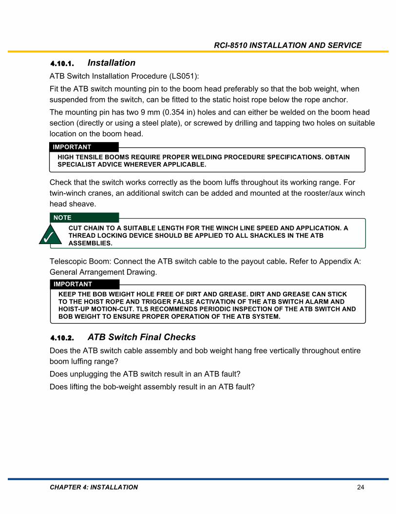
4.10.1. Installation ATB Switch Installation Procedure (LS051): Fit the ATB switch mounting pin to the boom head preferably so that the bob weight, when suspended from the switch, can be fitted to the static hoist rope below the rope anchor. The mounting pin has two 9 mm (0.354 in) holes and can either be welded on the boom head section (directly or using a steel plate), or screwed by drilling and tapping two holes on suitable location on the boom head.
Check that the switch works correctly as the boom luffs throughout its working range. For twin-winch cranes, an additional switch can be added and mounted at the rooster/aux winch head sheave.
Telescopic Boom: Connect the ATB switch cable to the payout cable. Refer to Appendix A: General Arrangement Drawing.
4.10.2. ATB Switch Final Checks Does the ATB switch cable assembly and bob weight hang free vertically throughout entire boom luffing range? Does unplugging the ATB switch result in an ATB fault? Does lifting the bob-weight assembly result in an ATB fault?
IMPORTANT HIGH TENSILE BOOMS REQUIRE PROPER WELDING PROCEDURE SPECIFICATIONS. OBTAIN SPECIALIST ADVICE WHEREVER APPLICABLE.
NOTE CUT CHAIN TO A SUITABLE LENGTH FOR THE WINCH LINE SPEED AND APPLICATION. A THREAD LOCKING DEVICE SHOULD BE APPLIED TO ALL SHACKLES IN THE ATB ASSEMBLIES.
IMPORTANT KEEP THE BOB WEIGHT HOLE FREE OF DIRT AND GREASE. DIRT AND GREASE CAN STICK TO THE HOIST ROPE AND TRIGGER FALSE ACTIVATION OF THE ATB SWITCH ALARM AND HOIST-UP MOTION-CUT. TLS RECOMMENDS PERIODIC INSPECTION OF THE ATB SWITCH AND BOB WEIGHT TO ENSURE PROPER OPERATION OF THE ATB SYSTEM.

RCI-8510 INSTALLATION AND SERVICE
CHAPTER 4: INSTALLATION 25
4.11. Luffing Ram/Boom Lift Cylinder Pressure Transducers Pressure transducers are fitted into the luffing cylinder(s) of hydraulic luffing cranes. In some cases with twin luffing cylinders (for example, when a cylinder equalization tube is not fitted, due to uneven boom raising and lowering forces between the two luffing cylinders) it may be necessary to install three pressure transducers: one on each piston side and one on a rod side.
Figure 10: Pressure Transducer Samples
4.11.1. Luff Cylinder Annular (rod) side: Install the appropriately marked pressure transducer into the hydraulic line feeding the top of the boom luffing cylinder.
Force (piston) side: Install the appropriately marked pressure transducer into the hydraulic line feeding the bottom of the boom luffing cylinder.
Cabling: Firmly fix pressure transducer cables to the crane structure and route them to the RCI-8510 wiring harness. Ensure freedom of movement around moving parts, such as the boom pivot pin. Secure cables at approximately 60 cm (24 in) intervals.
sm_8522_0007b
IMPORTANT ENSURE THAT THE TRANSDUCER IS FITTED TO DIRECTLY READ THE INTERNAL PRESSURE WITHOUT BEING INFLUENCED BY OUTSIDE CHECK VALVES (OR SIMILAR).
IMPORTANT ENSURE THAT THE TRANSDUCER IS FITTED TO DIRECTLY READ THE INTERNAL PRESSURE WITHOUT BEING INFLUENCED BY OUTSIDE CHECK VALVES (OR SIMILAR).

RCI-8510 INSTALLATION AND SERVICE
CHAPTER 4: INSTALLATION 26
4.11.2. Pressure Transducer Final Checks • Is the cable connector properly seated and no more than finger-tight?
• Is the sensor cable and sensor protected from snagging and damage?
• Is physical protection adequate to prevent damage due to falling objects and personnel using the sensor as a stepping point?
• Are there any visible signs of hydraulic fluid leakage after several minutes with hydraulics at pressure, under load?
4.12. Cabling
• All cabling used must be either UV-resistant or protected by UV-protective socking or conduit.
• Sensor cables should be fixed firmly to the crane and routed along the boom chords (and gantry/A-frame for the force transducer) through to the RCI-8510 controller wiring harness.
• Ensure that there is freedom of movement around the boom pivot pin.
• Secure cables at approximately 600 mm (24 in) intervals or where suitable to secure them firmly to the crane.
4.12.1. Cable Routing Sensor cables should be firmly fixed to the crane and routed along the boom chords (and gantry/A-frame for the force transducer) to the RCI in the cabin or junction box location. Ensure freedom of movement around the boom pivot pin. Secure cables at approximately 600 mm (24 in) intervals or where suitable, to secure the cable to the crane. Where possible protect cabling from direct sunlight, abrasion and physical damage.
IMPORTANT DO NOT OVER-TIGHTEN AS THIS CAN FORCE THE O-RING OUT OF ITS SEAT THUS LOSING ITS IP 67 PROTECTION LEVEL.
IMPORTANT THE FOLLOWING INFORMATION CONTAINS GENERAL GUIDELINES. ALL EQUIPMENT MUST BE INSTALLED IN ACCORDANCE WITH THE MANUFACTURER’S INSTRUCTIONS AND FOLLOWING THE RELEVANT INSTALLATION STANDARDS AND CODES OF PRACTICE.
IMPORTANT ALL ELECTRICAL CABLING MUST BE INSTALLED BY TECHNICALLY TRAINED PERSONNEL USING TRADE, PROFESSIONAL OR LOCALLY/INTERNATIONALLY RECOGNIZED STANDARD PROCEDURES.
RCI-8510 INSTALLATION AND SERVICE
CHAPTER 4: INSTALLATION 27
4.12.2. Cable Reels For cranes with varying Main Boom lengths a cable reel is typically used to feed the Main Hoist Rope and Auxiliary Hoist Rope ATB switch signals back to the RCI-8510 controller wiring harness. A junction box may also be included at the Main Boom tip to facilitate an Auxiliary hoist rope reeved on a jib or auxiliary boom head.
4.12.3. Compression Glands Optionally, a switch box may be provided with the RCI-8510 system. The switch box has metal cable glands and an internal grounding plate. The gland types used are designed to trap the braid or screen (or armor) within the braid for maximum EMI protection. Failure to terminate the screens in the glands may void the RCI-8510 system’s EMC compliance, and places the unit at risk of malfunction due to EMI.
4.12.4. Earthing Requirements In order for the RCI system to operate reliably and accurately and have maximum protection against nearby lightning strikes the following grounding must be applied: Ensure that the crane boom is earthed through a grounding strap or by other means. Verify its integrity.
When using a switch box, ensure that the sensor cable shielding is captured in the cable glands and that the cable glands are in good contact with the internal earthing plate. Ensure that the RCI-8510 controller or switch box earth lug is connected to the crane chassis using a minimum ground strap wire of either 12 awg or 2.5mm2 cross-sectional area. The earthing point must be a common ground rail for all interconnected electronic subsystems.
IMPORTANT DO NOT ROUTE SIGNAL CABLES NEXT TO POWER CABLES. SEPARATE CABLE TRAYS SHOULD EXIST FOR THE TWO TYPES OF CABLES TO AVOID EMI.
IMPORTANT DO NOT GROUND SCREENED CABLE SHIELDS AT BOTH ENDS; THEY ONLY NEED TO BE TRAPPED IN THE GLAND AT THE ENCLOSURE.
IMPORTANT THE CRANE BOOM EARTHING STRAP (OR OTHER EARTHING MEASURE) MUST BE IN PLACE. IF THE CRANE BOOM IS NOT EARTHED, THEN A VOLTAGE POTENTIAL MAY EXIST BETWEEN THE CABLE SHIELDS/ARMOUR AND THE BOOM, WHICH MAY CAUSE ERRATIC LOAD READINGS.
IMPORTANT THE CHASSIS, BOOM, OR JIB MUST NOT IN ANY CASE BE USED AS A SIGNAL RETURN OR GROUND PATH.

RCI-8510 INSTALLATION AND SERVICE
CHAPTER 4: INSTALLATION 28
4.12.5. Switch Box Retrofit systems may be supplied with a junction box, commonly referred to as a switch box. The switch box contains:
• RCI-8510 Controller
• DIN rail terminals
• Light stack relays
• Override Key switch
• Power fuse block
• Cable glands

RCI-8510 INSTALLATION AND SERVICE
CHAPTER 4: INSTALLATION 29
4.13. Snubber Diodes on Relays and Solenoids
Inductive loads must use snubber diodes on the coils (solenoids and relays) paying particular care to ensure correct polarity connection of the snubber diodes. TLS recommends fitting a 1N5404, 1N4004 or similar diode for back EMF suppression. Back EMF voltage spikes over 200VDC are commonly generated when relays and solenoids de-energize and these spikes can cause damage to other electrical equipment on the crane.
Figure 11: Snubber Diode Installation
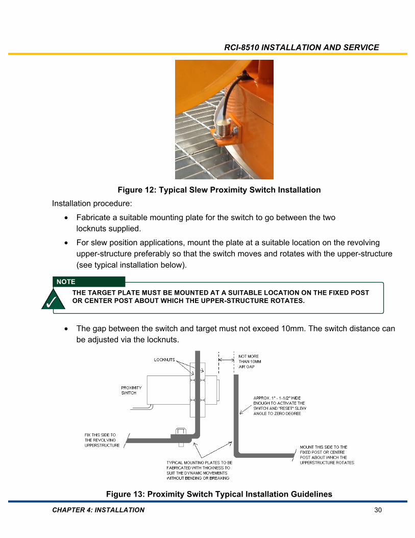
4.14. Proximity Switches Proximity switches provided by TLS are usually inductive type switches, meaning the switch is activated by close proximity to a ferrous metal target. Magnetic Proximity switches are also available in which case a magnetic target must also be installed.
IMPORTANT ALL INDUCTIVE LOADS SUCH AS RELAYS AND SOLENOIDS REQUIRE SNUBBER DIODES FOR TRANSIENT SUPPRESSION.
RCI-8510 INSTALLATION AND SERVICE
CHAPTER 4: INSTALLATION 30
Figure 12: Typical Slew Proximity Switch Installation
Installation procedure:
• Fabricate a suitable mounting plate for the switch to go between the two locknuts supplied.
• For slew position applications, mount the plate at a suitable location on the revolving upper-structure preferably so that the switch moves and rotates with the upper-structure (see typical installation below).
• The gap between the switch and target must not exceed 10mm. The switch distance can be adjusted via the locknuts.
Figure 13: Proximity Switch Typical Installation Guidelines
NOTE THE TARGET PLATE MUST BE MOUNTED AT A SUITABLE LOCATION ON THE FIXED POST OR CENTER POST ABOUT WHICH THE UPPER-STRUCTURE ROTATES.
RCI-8510 INSTALLATION AND SERVICE
CHAPTER 4: INSTALLATION 31
4.15. Digital Inputs and Outputs Description
To cater for a wide range of applications the RCI-8510 has the following inputs and outputs:
• 27 digital input channels including two ATB inputs
• 10 digital output channels including two relay outputs and three light stack outputs
4.15.1. Digital Inputs Digital inputs can be used for a variety of uses:
• Proximity switches such as: o Crane slew o Telescoping boom o Stabilizer/outrigger
• Limit switches such as: o High boom angle o Low boom angle
• Switch inputs to select different load charts
• Wind speed
• Over-ride key switch A fail-safe approach is used so that digital inputs are normally configured to reduce RC unless energized.
4.15.2. Digital Outputs Digital outputs can be used for a wide range of uses including:
• External audible alarm • Boom up, or down motion cut • Minimum radius motion cut • Clock-wise and counter-clockwise slew motion cut
NOTE THESE CHANNELS ARE NOT ISOLATED FROM THE CRANE POWER SUPPLY SO YOU MUST ENSURE THAT POTENTIAL HIGH CURRENT GROUND PATHS THROUGH THE RCI-8510 ARE NOT CREATED.
RCI-8510 INSTALLATION AND SERVICE
CHAPTER 4: INSTALLATION 32
A fail-safe approach is used so that digital outputs are normally configured to limit crane movements or reduce RC unless energised. It is recommended that outputs should drive slave relays. The digital output circuitry is current limited, which prevents short-duration short-circuits from damaging outputs. In the case of long term short circuits damage to the outputs may occur. This can occur by incorrect wiring during installation or a short in an output circuit. When used as digital outputs the digital channel provides an open collector switched output capable of shunting up to 100 mA. This output signal may be used to energise slave relays or drive indicator lamps under software control. When a digital output is ON it provides a current shunt to DGND or VEX; when a digital output is OFF it is an open circuit. Each of the relay outputs have read-back capability, thus a system fault will be triggered if the relay contact state does not match the expected relay state. Switching the override key on will normally energize all digital outputs. Note that when the motion cut relay has de-energized there is an in-built 5 second delay before it can be re-energized (provided the fault condition is cleared and the RCI-8510 is not in an alarm state). This feature helps avoid dynamic situations following motion cut, especially if activated during luffing down operations at higher boom angles.
4.15.3. Identifying and Connecting Digital Inputs and Outputs Refer to Appendix C: Software Configuration for a list of all digital inputs and outputs. Each digital input and output is described and polarity is also listed for each input and output. Refer to Appendix A: General Arrangement Drawings which shows the wiring for all digital inputs and outputs.
NOTE
IF SLAVE RELAYS ARE USED THEN SNUBBER DIODES MUST BE FITTED. REFER TO SECTION 4.28 SNUBBER DIODES ON RELAYS AND SOLENOIDS.
IMPORTANT SOME GENERAL ASSEMBLY DRAWINGS COVER A RANGE OF CRANE CONFIGURATIONS, WHICH MAY INCLUDE INPUTS AND OUTPUTS THAT ARE NOT USED ON THIS CRANE. IGNORE AN INPUT OR OUTPUT IF IT DOES NOT APPEAR ON THE CONFIGURATION SHEET.
IMPORTANT ALWAYS CHECK THAT THE WA NUMBER RECORDED IN APPENDIX C: SOFTWARE CONFIGURATION MATCHES THE WA NUMBER THAT APPEARS ON HOME SCREEN.

RCI-8510 INSTALLATION AND SERVICE
CHAPTER 4: INSTALLATION 33
4.16. Analog Inputs Description
The RCI-8510 has eight Analog sensor input channels. Each Analog input channel has individual programmable input gain circuitry and a 12 bit resolution ADC. The input circuitry can be programmed for:
• Four differential input signals (mV/V) (Each differential sensor uses a pair of input channels)
• Eight single ended signals (4-20 milliamp or 0-5VDC) input signals
• Or any combination thereof
• Each channel also has a programmable gain
4.16.1. Sensor Excitation The excitation supply provides power for the sensors. Two outputs are provided (precision +5.00 V or +15 V). The +5 VEX output can only supply up to 100 milliamps of current. The +15 VEX output can only supply up to 1 amp of current. If either of these signals are shorted to ground or loaded down below their limits then the RCI will detect a fault condition and activate motion-cuts until the fault is removed.
4.16.2. Identifying and Connecting Analog Sensor Inputs Refer to Appendix C: Software Configuration for a list of all Analog sensor inputs. Refer to Appendix A: General Arrangement Drawings which shows the wiring for all Analog inputs. RCI-8510 systems will normally be shipped with Analog sensor cables terminated and labeled for easy connection.
NOTE
THESE SETTINGS ARE PRESET AT THE FACTORY IN THE RCI CONFIGURATION FILES AND CANNOT BE MODIFIED ON SITE.

RCI-8510 INSTALLATION AND SERVICE
CHAPTER 5: CALIBRATION 34
5. Calibration
5.1. Overview This chapter describes all RCI-8510 system calibration tasks. When troubleshooting a problem only re-calibrate the RCI-8510 system after all other tests have been performed. The following data is stored in the RCI-8510:
• Load charts
• Crane geometry
• Alarm and motion control settings
• Data logging parameters
• Fine-tuning settings
• Other variables As this data varies between cranes and even crane models, this data may have to be changed occasionally onsite during installation. The default values delivered with the RCI-8510 system are listed in Appendix C: Software Configuration. Note that TLS is often not supplied with complete and accurate measurements.
5.2. Set Language Depending on the software package, various languages are available. To set the language go to Home > Language. Rotate the knob then KNOB CENTER PRESS twice to select preferred language.
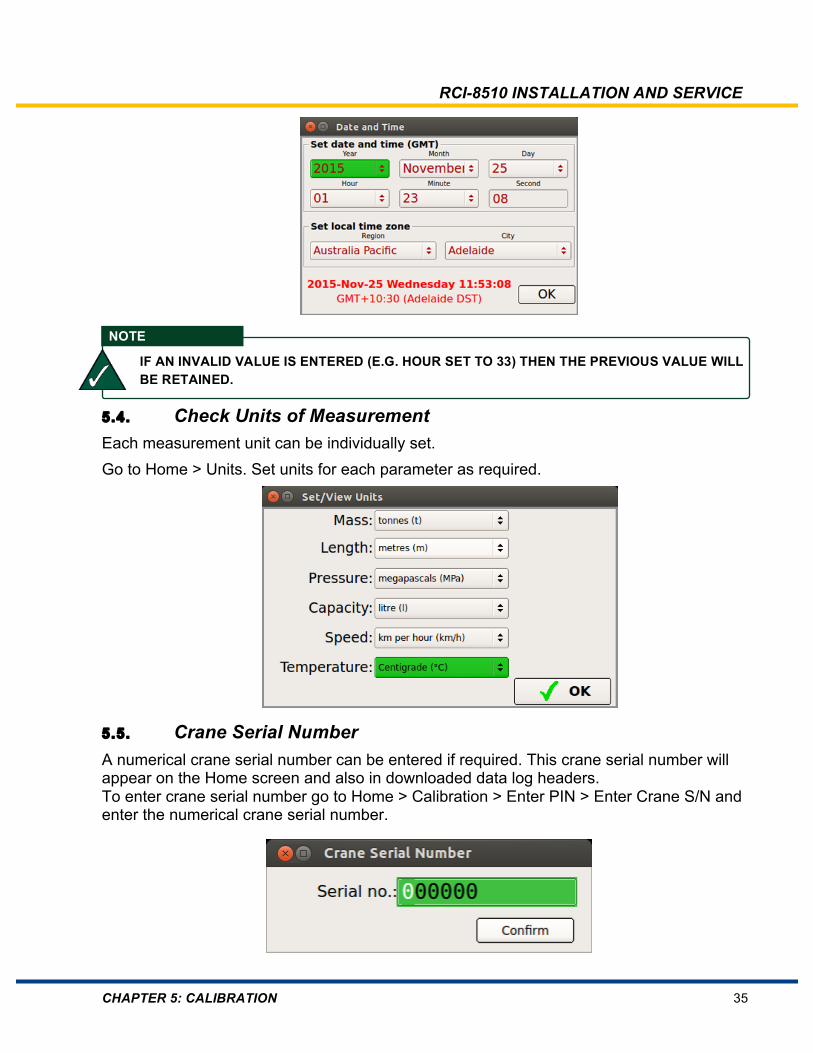
5.3. Check/Set Date and Time GMT (UTC) date/time must be set for data logging purposes. A local offset is then selected (by world region then state/city etc.) to ensure local time is correctly displayed. Go to Home > Calibration Menu > Set Date and Time. GMT (UTC) time and local offset can now be set.
RCI-8510 INSTALLATION AND SERVICE
CHAPTER 5: CALIBRATION 35
5.4. Check Units of Measurement Each measurement unit can be individually set. Go to Home > Units. Set units for each parameter as required.
5.5. Crane Serial Number A numerical crane serial number can be entered if required. This crane serial number will appear on the Home screen and also in downloaded data log headers. To enter crane serial number go to Home > Calibration > Enter PIN > Enter Crane S/N and enter the numerical crane serial number.
NOTE
IF AN INVALID VALUE IS ENTERED (E.G. HOUR SET TO 33) THEN THE PREVIOUS VALUE WILL BE RETAINED.

RCI-8510 INSTALLATION AND SERVICE
CHAPTER 5: CALIBRATION 36
5.6. Sensor Overview The RCI-8510 system uses sensors to monitor the crane’s working environment. Analog signals from these sensors are converted though an ADC (Analog to digital converter) to raw counts in the range of 0 - 4095, with a normal operating range of 100 – 4000. Both the calibrated and un-calibrated signal from a sensor can be viewed in the Live View Analog screen (Home > Diagnostics > Live View Analog).
When observing the un-calibrated signal (values in green), ensure that the raw counts stay within 50 - 4050 as the sensor operates through its operating range. Also ensure that the raw counts increase or decrease in a regular, smooth progression. If the change is irregular (for example, changes by more than 10) check the connections for that sensor. If the raw count is less than 50 or more than 4050 it is likely that there is a short circuit on that input channel (for example, the cable has been crushed and has an internal short circuit) or an open circuit on that input channel (for example a broken or disconnected lead). Moisture in plugs can also appear like short circuits. Before starting calibration this above screen should be viewed and all sensors operated (luff up/down, telescope in/out) and ensure that all raw counts stay within range. If any values are below 50 or above 4050, or don’t change, then check that sensor and sensor cabling. If a slew zone encoder is installed, verify that its raw counts increment/decrement as the boom slews left/right. Confirm operation of proximity sensors (where fitted). If a wind sensor is installed, ensure that the anemometer is free to rotate, and that a measurement is present in the display unit (anemometers are pre-calibrated). Check the operation of any other sensor and inputs. Once all sensors appear to be working correctly then sensor calibration can begin.

RCI-8510 INSTALLATION AND SERVICE
CHAPTER 5: CALIBRATION 37
5.7. Calibrating Boom Angle and Length The following procedures detail boom angle and boom length calibration.
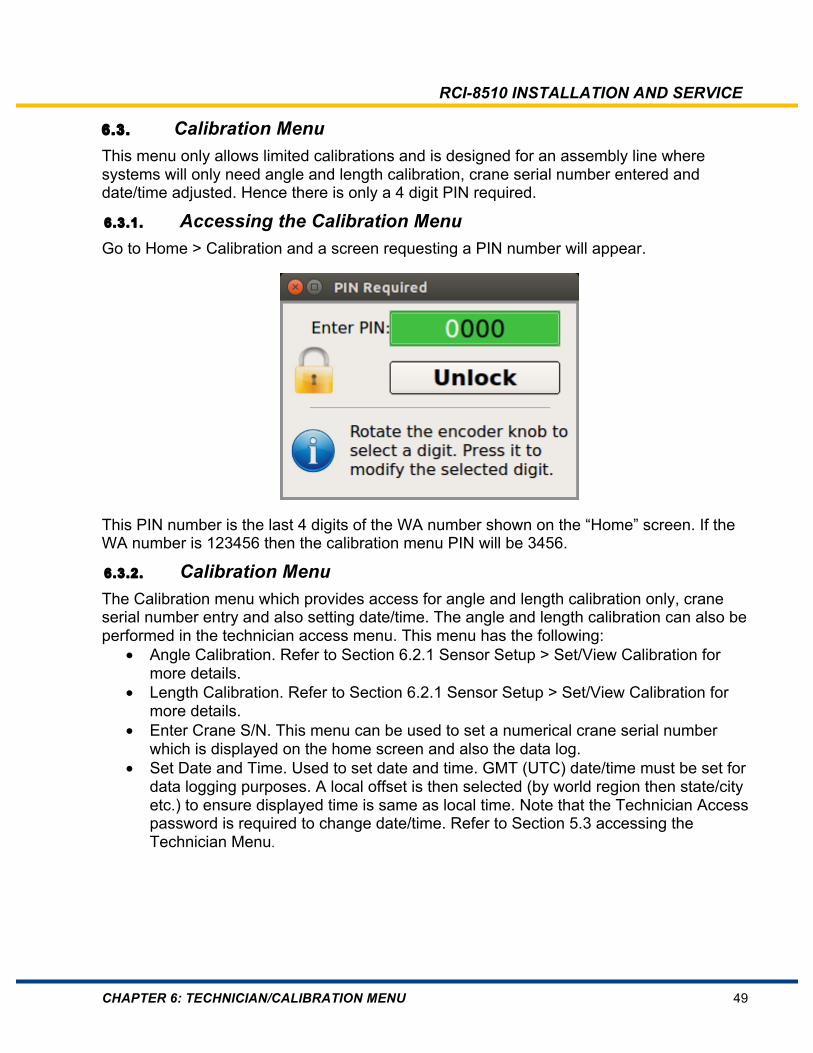
5.7.1. Accessing the Calibration Menu Go to Home > Calibration and a screen requesting a PIN number will appear.
This PIN number is the last 4 digits of the WA number shown on the “Home” screen. If the WA number is 123456 then the calibration menu PIN will be 3456.
Overview Most tasks are intuitively ordered, just requiring KNOB CENTER PRESS to accept and advance and using the rotary knob to change digits. If a different window requires
highlighting, use the cycle button until the required window is highlighted. Soft key (F1-F11) menu selections can either be selected by pressing appropriate F key or rotating the knob until the appropriate window is highlighted, then KNOB CENTER PRESS.
5.7.2. Calibrate Boom Angle Two different angle inclinometers may be used with this RCI-8510 system – a circular 0-5V 90° type or a square 4-20mA 180° type. The boom angle inclinometer may be in the recoil drum (telescopic crane), another type of enclosure (lattice boom crane) or mounted directly on the boom. The type of boom angle sensor is identified in Appendix C: Software Configuration. Raw count ranges differ between these inclinometers:
• 0-5V inclinometers raw count range is 1350-2550
• 4-20mA inclinometers raw count range is 750-3900

RCI-8510 INSTALLATION AND SERVICE
CHAPTER 5: CALIBRATION 38
Figure 14: 0-5V Inclinometer and 4-20mA Inclinometer To calibrate boom angle:
• Go to Home > Calibration > Enter PIN >.Sensor Setup > Live View Analog
• Ensure that the crane is on firm and level ground (to within ±1°).
• Luff the boom through its full operating range.
• The raw counts should smoothly change while luffing the boom and stay within the appropriate range (see above).
• If the raw counts are outside this range: o Luff the boom to minimum angle. o Remove the inclinometer recoil drum cover or enclosure cover if required. o Loosen the inclinometer securing screws, or remove the inclinometer if it is a square
4-20mA type. o Rotate the inclinometer until the raw counts read at either end of their appropriate
range (depending on the boom position, and whether the raw counts rise or fall as you luff the boom up).
o Tighten the inclinometer securing screws or refit the inclinometer if it is a square 4-20mA type.
o Luff the boom through its full operating range and ensure that the raw counts stay within their appropriate range.
o If required, refit the recoil drum or enclosure cover.
RCI-8510 INSTALLATION AND SERVICE
CHAPTER 5: CALIBRATION 39
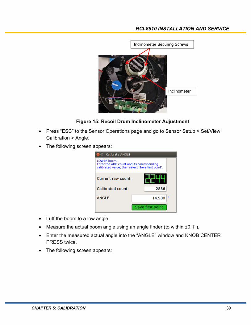
Figure 15: Recoil Drum Inclinometer Adjustment
• Press “ESC” to the Sensor Operations page and go to Sensor Setup > Set/View Calibration > Angle.
• The following screen appears:
• Luff the boom to a low angle.
• Measure the actual boom angle using an angle finder (to within ±0.1°).
• Enter the measured actual angle into the “ANGLE” window and KNOB CENTER PRESS twice.
• The following screen appears:
Inclinometer Securing Screws
Inclinometer
RCI-8510 INSTALLATION AND SERVICE
CHAPTER 5: CALIBRATION 40
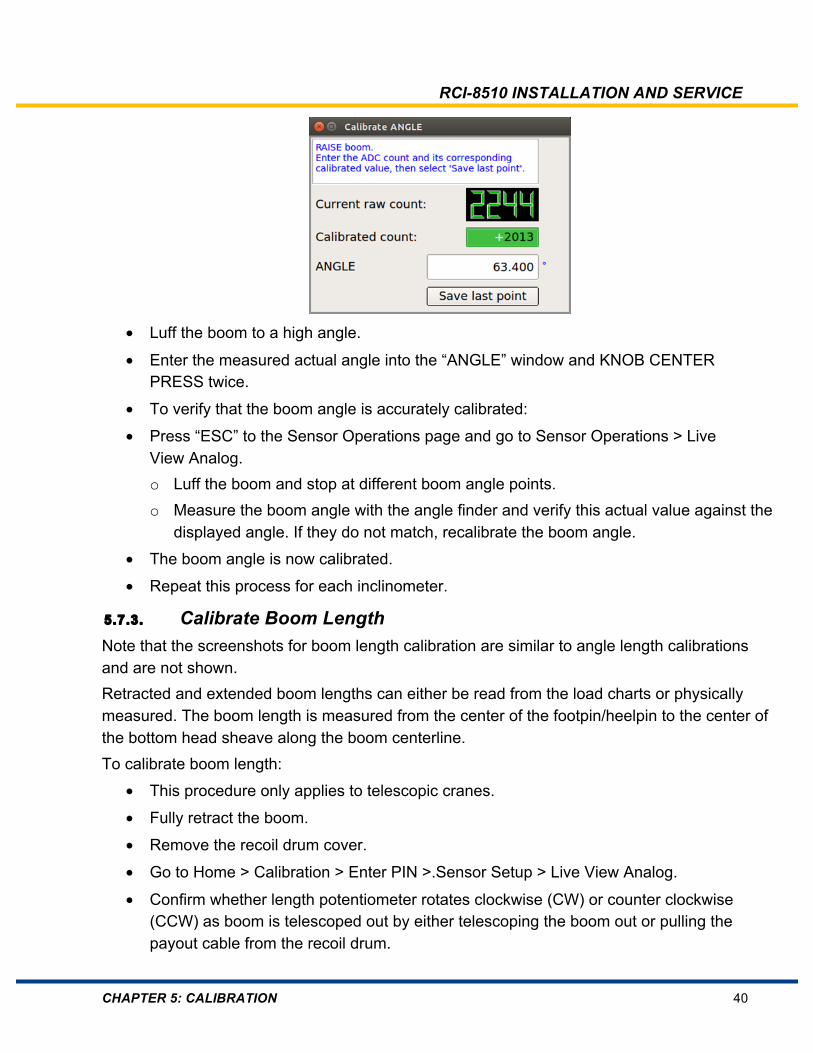
• Luff the boom to a high angle.
• Enter the measured actual angle into the “ANGLE” window and KNOB CENTER PRESS twice.
• To verify that the boom angle is accurately calibrated:
• Press “ESC” to the Sensor Operations page and go to Sensor Operations > Live View Analog. o Luff the boom and stop at different boom angle points. o Measure the boom angle with the angle finder and verify this actual value against the
displayed angle. If they do not match, recalibrate the boom angle.
• The boom angle is now calibrated.
• Repeat this process for each inclinometer.
5.7.3. Calibrate Boom Length Note that the screenshots for boom length calibration are similar to angle length calibrations and are not shown. Retracted and extended boom lengths can either be read from the load charts or physically measured. The boom length is measured from the center of the footpin/heelpin to the center of the bottom head sheave along the boom centerline. To calibrate boom length:
• This procedure only applies to telescopic cranes.
• Fully retract the boom.
• Remove the recoil drum cover.
• Go to Home > Calibration > Enter PIN >.Sensor Setup > Live View Analog.
• Confirm whether length potentiometer rotates clockwise (CW) or counter clockwise (CCW) as boom is telescoped out by either telescoping the boom out or pulling the payout cable from the recoil drum.

RCI-8510 INSTALLATION AND SERVICE
CHAPTER 5: CALIBRATION 41
• If the length potentiometer rotates CW as the boom telescopes out, pull back the length potentiometer assembly lever against the spring and rotate the gear so that the length potentiometer is fully CCW. Then rotate the gear so that the length potentiometer rotates one quarter turn CW.
• If the length potentiometer rotates CCW as the boom telescopes out, pull back the length potentiometer assembly lever against the spring and rotate the gear so that the length potentiometer is fully CW. The rotate the gear so that the length potentiometer rotates one quarter turn CCW.
Figure 16: Recoil Drum Potentiometer Adjustment
• Release the lever and allow the gears to mesh.
• Fully extend the boom and ensure that raw counts change smoothly as the boom telescopes and stays within the 50-4050 range.
• Fully retract the boom.
• Press “ESC” to the Sensor Operations page and go to Sensor Setup > Set/View Calibration > Length.
• Enter the fully retracted boom length into the “LENGTH” window for “Save first point” and KNOB CENTER PRESS twice.
• Fully extend the boom.
• Enter the fully extended boom length into the “LENGTH” window for “Save last point” and KNOB CENTER PRESS twice.
• To verify that the boom length is accurately calibrated:
• Press “ESC” to the Sensor Operations page and go to Sensor Setup > Live View Analog

RCI-8510 INSTALLATION AND SERVICE
CHAPTER 5: CALIBRATION 42
• Retract and fully extend the boom three times (to ensure reeling of payout cable settles inside drum).
• Measure boom length with a measuring tape and verify this actual value against the displayed length at three different boom lengths. If they do not match, recalibrate the boom length.
• The boom length is now calibrated.
• Repeat this process for all length sensors.
RCI-8510 INSTALLATION AND SERVICE
CHAPTER 6: TECHNICIAN/CALIBRATION MENU 43
6. Technician/Calibration Menu
6.1. Overview There are two main menus to access various functions for calibration etc.:
• The Technician Access Menu allows trained technicians to view, configure, calibrate and troubleshoot the RCI-8510 system.
• The Calibration menu which provides access for angle and length calibration only, crane serial number entry and also setting date/time.
The type of crane and sensor configuration determines which menu items are included. These are detailed in Appendix C: System Configuration Documentation. Some menu items may be duplicated for multiple components (for example you may see Sensor Setup Transducer 1 and Transducer 2).
6.2. Technician Access Menu Descriptions The following describes technician menu items. Not all of these may be in your software. There are also “Calibration Menu” items are also described below.
6.2.1. Sensor Setup The “Sensor Setup” menu is the main menu used for calibration. Menu items include:
Set/View Calibration In this menu calibrated value and raw data (raw counts) can be viewed for each sensor. Sensors can also be calibrated with this menu.
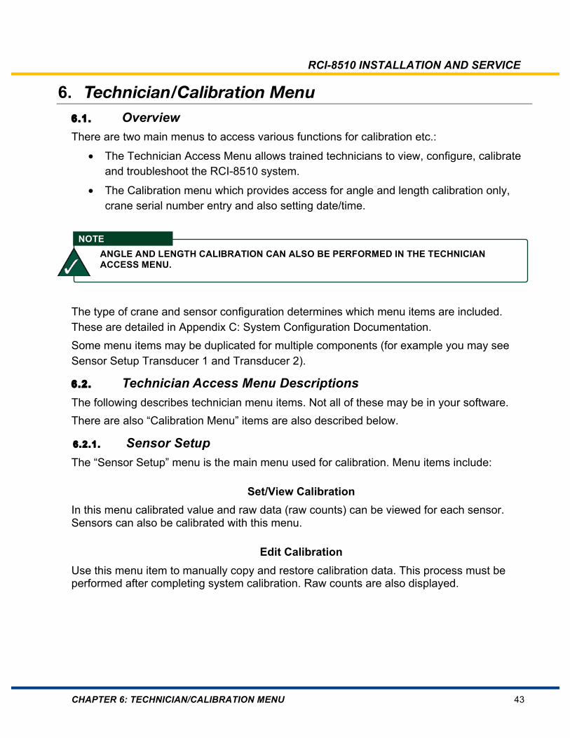
Edit Calibration Use this menu item to manually copy and restore calibration data. This process must be performed after completing system calibration. Raw counts are also displayed.
NOTE ANGLE AND LENGTH CALIBRATION CAN ALSO BE PERFORMED IN THE TECHNICIAN ACCESS MENU.
RCI-8510 INSTALLATION AND SERVICE
CHAPTER 6: TECHNICIAN/CALIBRATION MENU 44
Calibration values are recorded during the calibration process (i.e., low calibration value with corresponding sensor raw counts, high calibration value with corresponding raw counts). These values are Low Raw, Low Cal, High Raw and High Cal, and these values can be entered manually if calibration data is lost (for example, due to part replacement). These values are also useful when troubleshooting (where invalid calibrations can be easily identified by experienced technicians). This data can also be restored into the system by manually keying in the values without the need to operate the boom or lift known test loads. Where applicable, you can also use this function to validate default calibration values (useful when you load an updated software version which has correct sensor calibration data). In this case, only the Edit Calibration data for each sensor needs to be validated (instead of calibrating each sensor individually). To validate calibration data, access “Edit Calibration” for a sensor and KNOB CENTER PRESS until all fields have been accepted and display returns to “Sensor Operation” screen. Repeat for all other sensors as required. This menu item may also be used to calibrate transducers for load moment systems.
RCI-8510 INSTALLATION AND SERVICE
CHAPTER 6: TECHNICIAN/CALIBRATION MENU 45
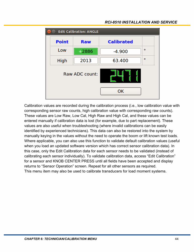
Live View Analog The “Live View Analog” screen shows live calibrated values and raw data for each sensor.
Figure 17: Live View Analog Screen This information is especially useful during installation and fault finding. Page 1 shows Analog sensors and page 2 may show additional sensors. Page 3 shows internal power supply voltages. Rotating the knob when the page screen is highlighted will show additional pages. This screen can also be accessed via Home > Diagnostics > Live View Analog without needing a PIN number.
RCI-8510 INSTALLATION AND SERVICE
CHAPTER 6: TECHNICIAN/CALIBRATION MENU 46
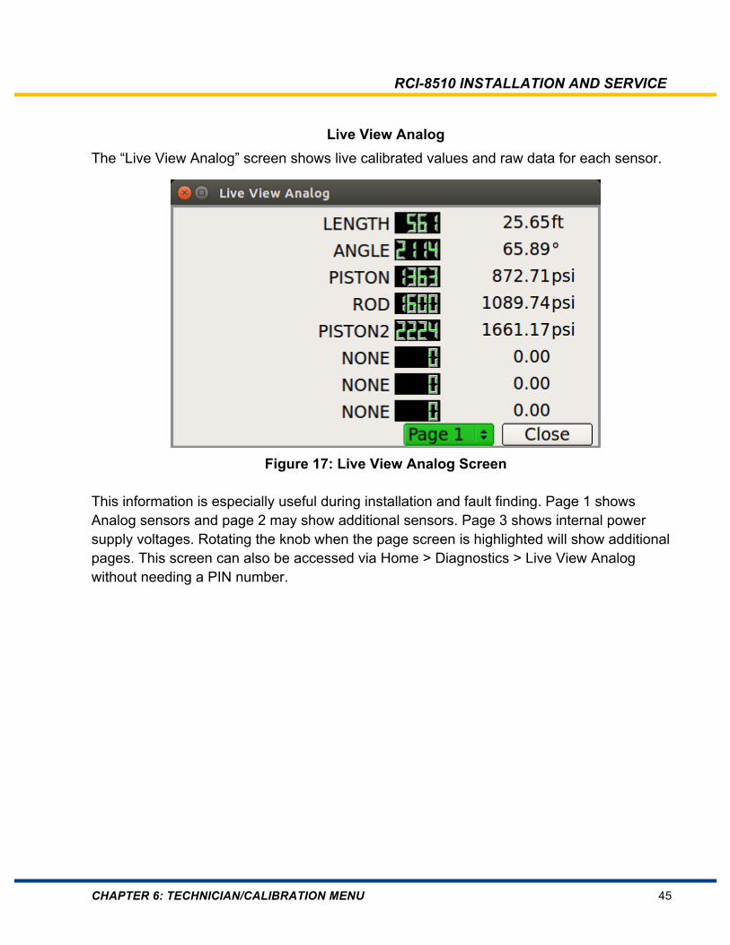
Live View Digital The “Live View Digital” screen shows the description and live status of all DI/O.
Figure 18: Live View Digital Screen Rotating the knob scrolls through the different pages of digital inputs and outputs. CENTER PRESSING the KNOB, then scrolling to an individual input or output and KNOB CENTER PRESS again will show a pop-up screen giving additional information on that digital input or output including RCI-8510 controller pin connection number. This screen can also be accessed via Home > Diagnostics > Live View Digital without needing a PIN number.
Non-Linear Calibration This may be used to enter non-linear calibration parameters. These parameters are normally preset by TLS before system delivery.
Set/View Wireless Sensors This function has not yet been implemented.

RCI-8510 INSTALLATION AND SERVICE
CHAPTER 6: TECHNICIAN/CALIBRATION MENU 47
Set/View Filtering This menu allows filtering of individual sensors. Filtering is sometimes required when a sensor value is unstable (jumping around) or is slow to reach actual value. It is recommended that default settings be kept. The following explains RCI-8510 filtering: The following 4 filter algorithms are used:
• Moving average: ValueN = ValueN-1 + (Input - ValueN-1) / FilterConstant. Filter Constant defines the number of steps used for the filter calculation
• Repeating average: At any reading of the current value from the ADC the value has to be added to the sum. At any N-th reading the sum will be divided by N. The following value will be set to zero for the next calculation. Value = SUM( Input1..InputN) / N
• Sliding window: At any reading of the current value from the ADC the value is stored in a cyclic buffer shifting out oldest value. The filter output is Value = SUM( Input1..InputN) / N. Where N is the number of last samples stored. Filter Constant defines the number of samples used for the filter calculation.
• Leaky integrator: At any reading of the current value from the ADC the output value is calculated using the following recursion algorithm y(n)=(1-POW(2,–K))*y(N–1)+x(N), where x is the input, y is the output, and N is the sample index. Using a power of two for K enables the use of right shifts in the code to avoid the performance hit from the multiplier blocks. Using a 32-bit integer for the summing block and delay accommodates the bits of growth in the output register. This is a low pass filter where the most recent value has the biggest weight.
Note that Filter Constants set will be converted to the nearest power of two values: 1,2,4,8,16,32,64…
6.2.2. Lift Thresholds Sets hook block allowance for main and any other winches. While lifting a load it is not possible to change the crane configuration (duty and Parts of Line). Without a load on the hook most cranes will display the hook block weight. Use this function to allow a hook block load value to be set, to allow configuration changes with a displayed load but no effective load lifted. There is one lift value setting for each monitored winch. When setting the lift value, the entered load should be slightly greater than the weight of the winch hook block.
6.2.3. Select Parts of Line Allows changing the number of Parts of Line on the selected winch without having to go back out to the normal operating screen.
6.2.4. Select Duty Allows changing the duty without having to go back to the normal operating screen.

RCI-8510 INSTALLATION AND SERVICE
CHAPTER 6: TECHNICIAN/CALIBRATION MENU 48
6.2.5. Data Logger Setup These menu items define data logging parameters.
Stable Load Time Sets duration which load must be stable in order to log.
Stable Load Variation Sets amount of allowed load variation to remain a stable load.
Reset Time Sets time when load is below threshold before load log cycle is complete.
Load Thresholds Sets load threshold percentages for lift counters and also minimum load logging %RC.
RCI-8510 INSTALLATION AND SERVICE
CHAPTER 6: TECHNICIAN/CALIBRATION MENU 49
6.3. Calibration Menu This menu only allows limited calibrations and is designed for an assembly line where systems will only need angle and length calibration, crane serial number entered and date/time adjusted. Hence there is only a 4 digit PIN required.
6.3.1. Accessing the Calibration Menu Go to Home > Calibration and a screen requesting a PIN number will appear.
This PIN number is the last 4 digits of the WA number shown on the “Home” screen. If the WA number is 123456 then the calibration menu PIN will be 3456.
6.3.2. Calibration Menu The Calibration menu which provides access for angle and length calibration only, crane serial number entry and also setting date/time. The angle and length calibration can also be performed in the technician access menu. This menu has the following:
• Angle Calibration. Refer to Section 6.2.1 Sensor Setup > Set/View Calibration for more details.
• Length Calibration. Refer to Section 6.2.1 Sensor Setup > Set/View Calibration for more details.
• Enter Crane S/N. This menu can be used to set a numerical crane serial number which is displayed on the home screen and also the data log.
• Set Date and Time. Used to set date and time. GMT (UTC) date/time must be set for data logging purposes. A local offset is then selected (by world region then state/city etc.) to ensure displayed time is same as local time. Note that the Technician Access password is required to change date/time. Refer to Section 5.3 accessing the Technician Menu.

RCI-8510 INSTALLATION AND SERVICE
CHAPTER 7: DATA LOGGER 50
7. Data Logger
Description The RCI-8510 maintains two data logs internally:
• Operational Log storing run-time parameters to replay crane incidents.
• Design Working Period Log storing Crane use data and Hoisting Mechanism (Winch) use data for calculating life of the crane and hoisting gear per AS2550.1:2011.
The internal Operation Log file is a circular file. As the log memory is used up the oldest pages are archived on the internal SD Card. Therefore the Operational data log always maintains the latest data, typically up to a month old but this depends on the use of the crane. These data logs are downloaded independently. The overall data retrieval process is described in detail in the RCI-8510 Operator Manual. Refer to the RCI-8510 Operator Manual for data log download procedures. Data-log settings can be viewed and changed at Home > Technician Access > Data Logger Setup, refer to Section 6.2.5 Data Logger Setup.

RCI-8510 INSTALLATION AND SERVICE
CHAPTER 8: SOFTWARE UPDATES 51
8. Software Updates
RCI-8510 software updates may be required for a variety of reasons including:
• Initial programming for RCI-8510
• New/amended load charts crane configuration Software updates are easily performed and software update instructions will always be sent with the software updates. Software update instructions are also available from our website: www.trimble.com/liftingsolutions

RCI-8510 INSTALLATION AND SERVICE
CHAPTER 9: TROUBLESHOOTING 52
9. Troubleshooting
9.1. Overview The RCI-8510 has very good in-built diagnostics and most faults can be narrowed down in a few minutes. Under normal operating conditions the “Spanner” icon in the bottom corner of the screen will be black. (Depending on software, the “Spanner” icon may not be normally visible on an A3 screen until the “Alarm Mute” button has been pressed.)
Figure 19: A6 Screen ("Spanner" icon bottom left)
Figure 20: A3 Screen ("Spanner" icon bottom right)
When a fault is detected the spanner icon will change color to red or orange (depending on software, on an A3 screen, the spanner icon becomes visible only when the “Alarm Mute” button is pressed.) Error messages will also scroll along the bottom of the screen. If a particular parameter is out of range, or fault, that parameter box on the display will change color to red.
RCI-8510 INSTALLATION AND SERVICE
CHAPTER 9: TROUBLESHOOTING 53
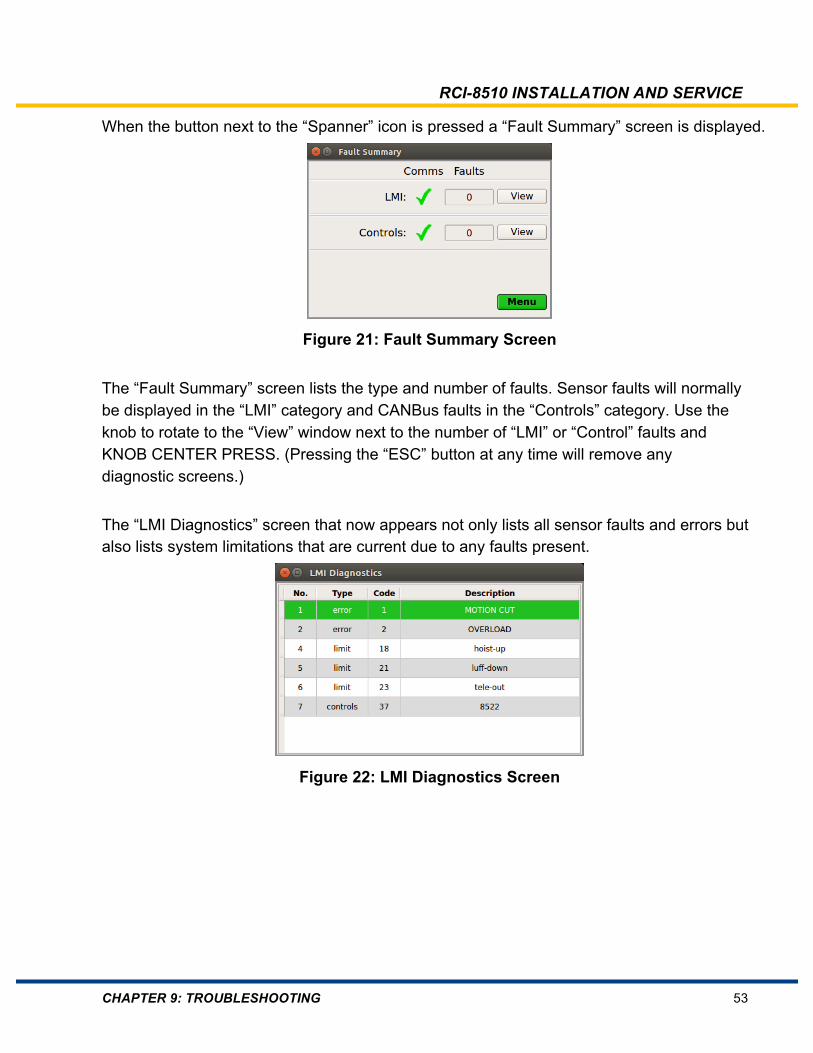
When the button next to the “Spanner” icon is pressed a “Fault Summary” screen is displayed.
Figure 21: Fault Summary Screen
The “Fault Summary” screen lists the type and number of faults. Sensor faults will normally be displayed in the “LMI” category and CANBus faults in the “Controls” category. Use the knob to rotate to the “View” window next to the number of “LMI” or “Control” faults and KNOB CENTER PRESS. (Pressing the “ESC” button at any time will remove any diagnostic screens.) The “LMI Diagnostics” screen that now appears not only lists all sensor faults and errors but also lists system limitations that are current due to any faults present.
Figure 22: LMI Diagnostics Screen

RCI-8510 INSTALLATION AND SERVICE
CHAPTER 9: TROUBLESHOOTING 54
A list of possible entries with explanation is listed below: Table 3: Diagnostic Error Codes
RciErr_MCUT 01 Motion Cut Rci_Err_OLOAD 02 Overload Alarm Rci_Err_ATB 03 Anti-Two Blocking (ATB1) Rci_Err_ORIDE 04 Override ON Rci_Err_Green 05 Green (no alarm) Rci_Err_Yellow 06 Yellow (no alarm) Rci_Err_ANGLE 07 Range (angle) Rci_Err_LENGTH 08 Range (length) Rci_Err_RADIUS 09 Range (radius) Rci_Err_HEIGHT 10 Range (height) Rci_Err_SLEW 11 Range (slew) Rci_Err_SENSOR 12 Sensor error Rci_Err_Red 13 RED (unused alarm) Rci_Err_RIGGING 14 Rigging mode Rci_Err_RCReset 15 RC reset (no alarm) Rci_Err_LINEPULL 16 Exceeded line pull Rci_Err_WindSpeed 17 Exceeded wind speed Rci_Err_LIMIT_HoistUp 18 Exceeded hoist UP limit Rci_Err_LIMIT_HoistDown 19 Exceeded hoist DOWN limit Rci_Err_LIMIT_LuffUp 20 Exceeded luff UP limit Rci_Err_LIMIT_LuffDown 21 Exceeded luff DOWN limit Rci_Err_LIMIT_TeleIn 22 Exceeded telescopic boom limit Rci_Err_LIMIT_TeleOut 23 Exceeded telescopic boom limit Rci_Err_LIMIT_SlewLeft 24 Exceeded slew LEFT limit Rci_Err_LIMIT_Slew Right 25 Exceeded slew RIGHT limit Rci_Err_SlingPull 26 Exceeded line pull for sling Rci_Err_Pitch 27 Exceeded pitch limit Rci_Err_Roll 28 Exceeded roll limit Rci_Err_ATB2 29 Second two block error Rci_Err_TravelMode 30 Travel Mode if SET else crane mode Rci_Err_AxleLoadLimit 31 Front axle load exceeded Rci_Err_CfgBackup 33 Configuration has backup Rci_Err_SysVoltage 34 System voltage fault Rci_Err_SysRelay 35 Relay fault Rci_Err_LoggedOff 36 User logged off (unauthorized state) Rci_Err_CAN_Open 37 CAN/Open error Rci_Err_CAN_J1939 38 CAN/J1939 error Rci_Err_LoadOnHook 39 Load present while hook stowed Rci_Err_PistonImbalance 40 Hydraulic piston imbalance Rci_Err_ValveFault 41 Error mask for hydraulic valves Rci_Err_SysMemory 55 System memory error
NOTE
THIS LIST IS DYNAMIC – AS FAULTS ARE CLEARED (OR OCCUR) ALL THE DIAGNOSTIC SCREENS ARE ALWAYS UPDATED TO SHOW CURRENT FAULT STATUS.
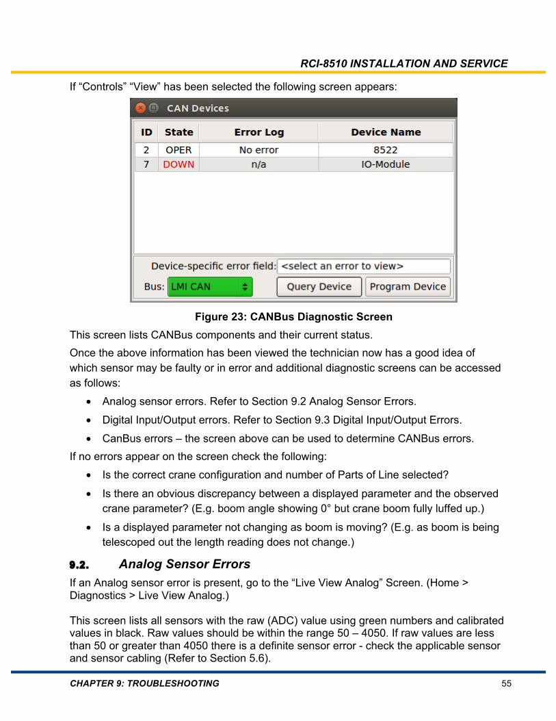
RCI-8510 INSTALLATION AND SERVICE
CHAPTER 9: TROUBLESHOOTING 55
If “Controls” “View” has been selected the following screen appears:
Figure 23: CANBus Diagnostic Screen This screen lists CANBus components and their current status. Once the above information has been viewed the technician now has a good idea of which sensor may be faulty or in error and additional diagnostic screens can be accessed as follows:
• Analog sensor errors. Refer to Section 9.2 Analog Sensor Errors.
• Digital Input/Output errors. Refer to Section 9.3 Digital Input/Output Errors.
• CanBus errors – the screen above can be used to determine CANBus errors. If no errors appear on the screen check the following:
• Is the correct crane configuration and number of Parts of Line selected?
• Is there an obvious discrepancy between a displayed parameter and the observed crane parameter? (E.g. boom angle showing 0° but crane boom fully luffed up.)
• Is a displayed parameter not changing as boom is moving? (E.g. as boom is being telescoped out the length reading does not change.)
9.2. Analog Sensor Errors If an Analog sensor error is present, go to the “Live View Analog” Screen. (Home > Diagnostics > Live View Analog.) This screen lists all sensors with the raw (ADC) value using green numbers and calibrated values in black. Raw values should be within the range 50 – 4050. If raw values are less than 50 or greater than 4050 there is a definite sensor error - check the applicable sensor and sensor cabling (Refer to Section 5.6).
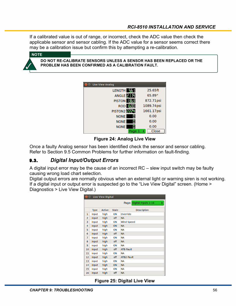
RCI-8510 INSTALLATION AND SERVICE
CHAPTER 9: TROUBLESHOOTING 56
If a calibrated value is out of range, or incorrect, check the ADC value then check the applicable sensor and sensor cabling. If the ADC value for a sensor seems correct there may be a calibration issue but confirm this by attempting a re-calibration.
Figure 24: Analog Live View Once a faulty Analog sensor has been identified check the sensor and sensor cabling. Refer to Section 9.5 Common Problems for further information on fault-finding.
9.3. Digital Input/Output Errors A digital input error may be the cause of an incorrect RC – slew input switch may be faulty causing wrong load chart selection. Digital output errors are normally obvious when an external light or warning siren is not working. If a digital input or output error is suspected go to the “Live View Digital” screen. (Home > Diagnostics > Live View Digital.)
Figure 25: Digital Live View
NOTE DO NOT RE-CALIBRATE SENSORS UNLESS A SENSOR HAS BEEN REPLACED OR THE PROBLEM HAS BEEN CONFIRMED AS A CALIBRATION FAULT.

RCI-8510 INSTALLATION AND SERVICE
CHAPTER 9: TROUBLESHOOTING 57
This screen displays all digital inputs and outputs. When this screen is displayed the first page shows digital inputs. As the knob is rotated further pages of digital inputs appear, then digital outputs. Each page lists the signal type, current state and signal description. This information is also dynamic and reflects current digital input or output status. If the KNOB is CENTER PRESSED then rotated, each signal, in turn is highlighted. If the KNOB is CENTER PRESSED on a signal, a pop-up window appears listing actual RCI-8510 pin number that this signal is connected to.
To fault find, select the appropriate page the digital input or output is listed on and check the status. For a digital input that is a switch, the switch can be operated and if the status on the page does not change then the switch and switch cabling should be checked. Refer to Section 9.4 Common Problems for further information on fault-finding.
9.4. Do Not Modify the Calibration It is rare for calibration data to be corrupted. When a re-calibration has been attempted in order to rectify a problem before that problem has been correctly identified, this often leads to added confusion as the perspective is moved from the real fault to "calibration problems". If the system had previously been operating correctly and suddenly developed a fault, the problem is likely to be something external to the display/controller rather than the calibration. An example: the mounting of the inclinometer has become loose and has allowed the inclinometer to move, hence altering the angle and radius and the RC. Alternatively, there may be a short circuit in one of the cables caused by excessive flexing or rubbing during use. On an initial installation, the calibration may well be at fault. Calibration data for a sensor can be seen at Home > Technician Access > Sensor Setup > Edit Calibration > then select appropriate sensor. If all of the external inputs appear to be operating correctly but the readouts do not show the correct values, then view all of the calibration data and record it. If in doubt, send a copy of this data to TLS, so that it can be analyzed. If this is not possible, re-calibration may be attempted.
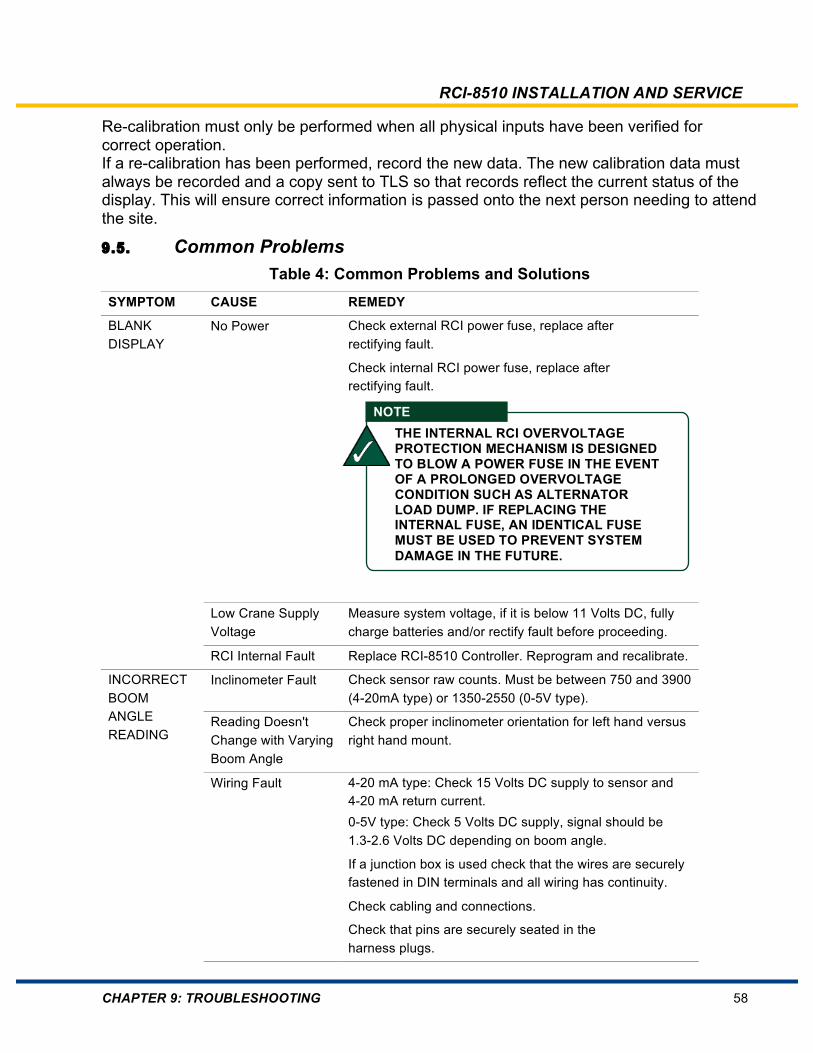
RCI-8510 INSTALLATION AND SERVICE
CHAPTER 9: TROUBLESHOOTING 58
Re-calibration must only be performed when all physical inputs have been verified for correct operation. If a re-calibration has been performed, record the new data. The new calibration data must always be recorded and a copy sent to TLS so that records reflect the current status of the display. This will ensure correct information is passed onto the next person needing to attend the site.
9.5. Common Problems Table 4: Common Problems and Solutions
SYMPTOM CAUSE REMEDY
BLANK DISPLAY
No Power Check external RCI power fuse, replace after rectifying fault.
Check internal RCI power fuse, replace after rectifying fault.
Low Crane Supply Voltage
Measure system voltage, if it is below 11 Volts DC, fully charge batteries and/or rectify fault before proceeding.
RCI Internal Fault Replace RCI-8510 Controller. Reprogram and recalibrate.
INCORRECT BOOM ANGLE READING
Inclinometer Fault Check sensor raw counts. Must be between 750 and 3900 (4-20mA type) or 1350-2550 (0-5V type).
Reading Doesn't Change with Varying Boom Angle
Check proper inclinometer orientation for left hand versus right hand mount.
Wiring Fault 4-20 mA type: Check 15 Volts DC supply to sensor and 4-20 mA return current. 0-5V type: Check 5 Volts DC supply, signal should be 1.3-2.6 Volts DC depending on boom angle.
If a junction box is used check that the wires are securely fastened in DIN terminals and all wiring has continuity.
Check cabling and connections.
Check that pins are securely seated in the harness plugs.
NOTE THE INTERNAL RCI OVERVOLTAGE PROTECTION MECHANISM IS DESIGNED TO BLOW A POWER FUSE IN THE EVENT OF A PROLONGED OVERVOLTAGE CONDITION SUCH AS ALTERNATOR LOAD DUMP. IF REPLACING THE INTERNAL FUSE, AN IDENTICAL FUSE MUST BE USED TO PREVENT SYSTEM DAMAGE IN THE FUTURE.

RCI-8510 INSTALLATION AND SERVICE
CHAPTER 9: TROUBLESHOOTING 59
Faulty Inclinometer Replace inclinometer paying careful attention to proper orientation.
Independently check inclinometer sensor using handheld 4-20 mA sensor tester.
INCORRECT BOOM LENGTH READING
Boom Length Sensor Fault
Check cable connections.
Check sensor raw counts. Must be between 50 and 4050.
Check that recoil drum potentiometer is properly positioned within range. The potentiometer should have a half-turn in reserve when boom is fully retracted.
Wiring Fault Check recoil drum cable connections. Potentiometer excitation voltage should be 5 Volts DC. Length signal should vary between 0.1 and 4.9 Volts DC.
Incorrect Configuration
Check programmed boom length sensor parameters.
Length Sensor not Calibrated
Perform boom length calibration procedure.
Broken Potentiometer
Damage can occur with over or under extension. Replace potentiometer. Recalibrate.
INCORRECT BOOM LENGTH READING Lattice boom cranes
Incorrect Duty/Hook Selected
Select correct duty/hook.
Incorrect RCI Configuration
Contact TLS Service.
INCORRECT PRESSURE TRANSDUCER READING
Pressure Sensor Fault
Check sensor raw counts. Must be between 100 and 4000. Replace pressure sensor if incorrect.
4-20 mA type: Independently check pressure sensor using handheld 4-20 mA sensor tester.
Wiring Fault Check 5 Volts DC/15 Volts DC supply to sensor and 4-20 mA return current.
Check cabling and connections.
Pressure Transducers not Calibrated
Use Enter Cal Data to manually set pressure transducer scaling factors.
INCORRECT RADIUS READING
Incorrect Boom Angle Reading
See "Incorrect Boom Angle Reading."
Incorrect Boom Length Reading
See "Incorrect Boom Length Reading."
Incorrect Crane Geometry
Verify crane geometry settings.
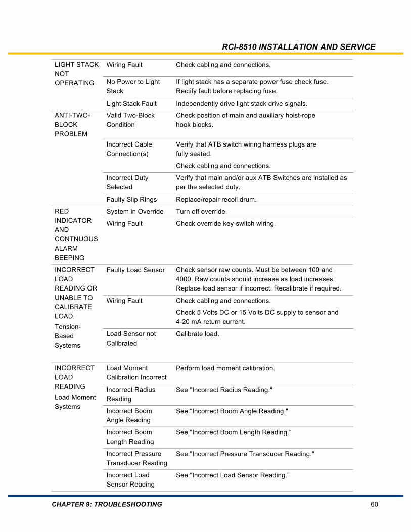
RCI-8510 INSTALLATION AND SERVICE
CHAPTER 9: TROUBLESHOOTING 60
LIGHT STACK NOT OPERATING
Wiring Fault Check cabling and connections.
No Power to Light Stack
If light stack has a separate power fuse check fuse. Rectify fault before replacing fuse.
Light Stack Fault Independently drive light stack drive signals.
ANTI-TWO-BLOCK PROBLEM
Valid Two-Block Condition
Check position of main and auxiliary hoist-rope hook blocks.
Incorrect Cable Connection(s)
Verify that ATB switch wiring harness plugs are fully seated.
Check cabling and connections.
Incorrect Duty Selected
Verify that main and/or aux ATB Switches are installed as per the selected duty.
Faulty Slip Rings Replace/repair recoil drum.
RED INDICATOR AND CONTNUOUS ALARM BEEPING
System in Override Turn off override.
Wiring Fault Check override key-switch wiring.
INCORRECT LOAD READING OR UNABLE TO CALIBRATE LOAD. Tension-Based Systems
Faulty Load Sensor Check sensor raw counts. Must be between 100 and 4000. Raw counts should increase as load increases. Replace load sensor if incorrect. Recalibrate if required.
Wiring Fault Check cabling and connections.
Check 5 Volts DC or 15 Volts DC supply to sensor and 4-20 mA return current.
Load Sensor not Calibrated
Calibrate load.
INCORRECT LOAD READING Load Moment Systems
Load Moment Calibration Incorrect
Perform load moment calibration.
Incorrect Radius Reading
See "Incorrect Radius Reading."
Incorrect Boom Angle Reading
See "Incorrect Boom Angle Reading."
Incorrect Boom Length Reading
See "Incorrect Boom Length Reading."
Incorrect Pressure Transducer Reading
See "Incorrect Pressure Transducer Reading."
Incorrect Load Sensor Reading
See "Incorrect Load Sensor Reading."
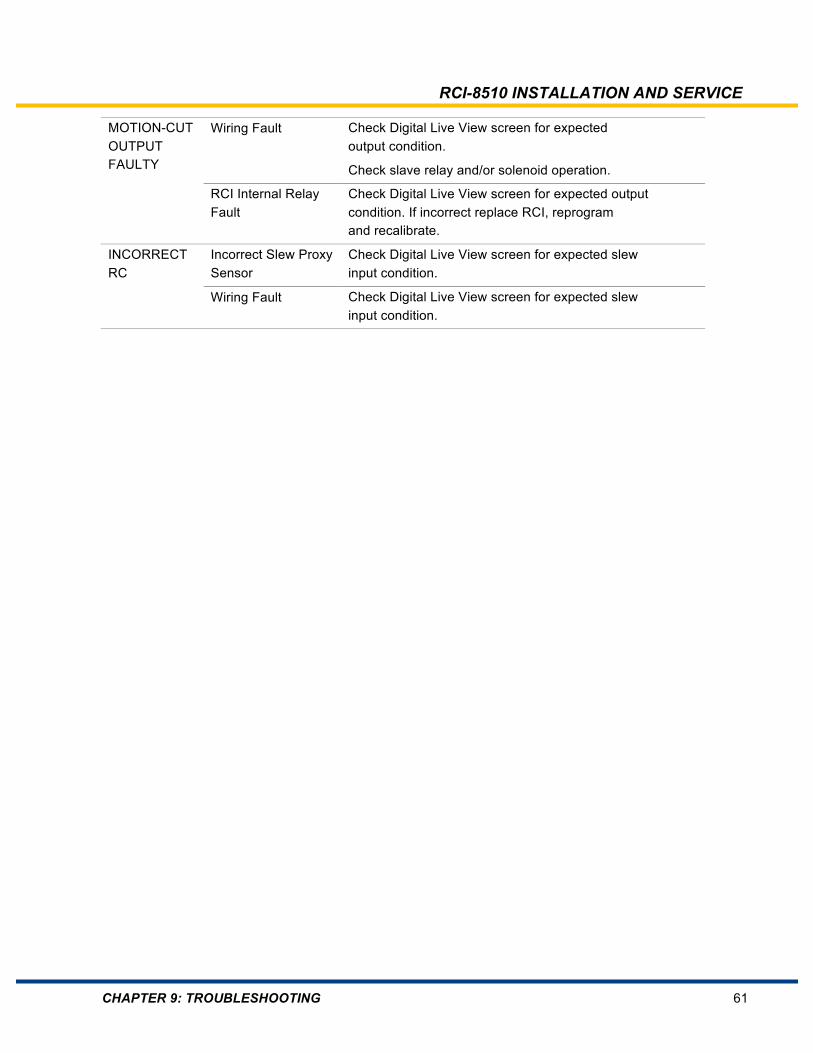
RCI-8510 INSTALLATION AND SERVICE
CHAPTER 9: TROUBLESHOOTING 61
MOTION-CUT OUTPUT FAULTY
Wiring Fault Check Digital Live View screen for expected output condition.
Check slave relay and/or solenoid operation.
RCI Internal Relay Fault
Check Digital Live View screen for expected output condition. If incorrect replace RCI, reprogram and recalibrate.
INCORRECT RC
Incorrect Slew Proxy Sensor
Check Digital Live View screen for expected slew input condition.
Wiring Fault Check Digital Live View screen for expected slew input condition.

RCI-8510 INSTALLATION AND SERVICE
CHAPTER 9: TROUBLESHOOTING 62
9.6. Contacting TLS Have the following information available if you need to contact TLS.
Table 5: Critical Information to Supply to TLS Information Description
Model Crane manufacturer
Serial No Crane serial number
WA Number Software job number
Controller: 8522 processor release Processor PCB release version
Display (app): Display application version
Display (o/s): Display operating version
ADR version: User interface version
This information is available from the “Home” screen.
Figure 26: Home Screen Taking a photo of the “Home” screen is often an easy way to send this information. Ensure that you can accurately describe the problem and what has been done to try and resolve the issue. Refer to back page of this manual for contact details for your area.

RCI-8510 INSTALLATION AND SERVICE
CHAPTER 10: SPECIFICATIONS 63
10. Specifications
These specifications are common to all RCI-8510 systems. Always consult the crane specific information for additional crane system specific information:
• Appendix A: General Arrangement Drawings
• Appendix B: Duty Listing
• Appendix C: System Configuration Documentation
• Appendix D: Component Drawings
Specifications are subject to change without notice.
10.1. Display Unit Dimensions (WxHxD) 7” A6: 175 x 145 x 85mm/6.8 x 5.7 x 3.3 in
4” A3: 198 x 98 x 59.5mm/7.8 x 3.9 x 2.4 in
Weight 7” A6: 1.0 kg/2.2 lbs 4” A3:
Protection Level IP 67
Display 7” or 4” TFT Color Graphic LCD with LED backlight
Mounting RAM bracket
Display Resolution
7” A6: 800 x 480 4” A6: 480 x 272
10.2. Controller 10.3. Environmental IEC 529 IP 66
Operating Temperature -20°C to +70°C -4°F to +158°F
Humidity 0 – 99% non-condensing
Shock IEC 600068-2-27 Half sinus, 1000 g (1 ms)

RCI-8510 INSTALLATION AND SERVICE
CHAPTER 10: SPECIFICATIONS 64
Vibration IEC 600068-2-6 5 – 500 Hz, 20 g, 10 mm
Housing Material Aluminum alloy
Overvoltage Protection Temporary over-voltage protection
10.4. Electrical 10.4.1. Power Supply Type Switching DC-DC Input Range 10.5–36 Volts DC Input Current 500 mA @ 24 Volts DC (dependent on individual hardware
and software) Reverse Voltage Protection
Yes
Overvoltage Protection 36 Volts DC - Crowbar circuit fuse protected
10.4.2. Analog Sensor Inputs Number 4 differential, or 8 single ended
Software configurable Type Single ended or differential
Software configurable Programmable gain
Range 0 – 20 mVolts DC 0 – 5 Volts DC 4 – 20 mA
Resolution 12 bits Protection Tranzorb
RC network
10.4.3. Fuses 3 A TBA 1.6 A slow-blow 5x20 Located internally
Bussman (BK/GMD-1.5-R)
10.4.4. Digital Inputs Number 27 Type Software configurable Configuration Factory configured for power or earth switching Isolation Optical

RCI-8510 INSTALLATION AND SERVICE
CHAPTER 10: SPECIFICATIONS 65
10.4.5. Digital Outputs Number 10 – 5 + 3 light bar outputs + 2 dedicated ATB inputs Configuration Factory configured for power or earth switching
10.4.6. Sensor Excitation +5.00 V Current source capability 100 mA
Accuracy ±1%
+15 V Current source capability 500 mA
10.4.7. Serial I/O RS-232 1 channel (Configuration and calibration upload/download, data
log download)
RS-485 1 channel (Telematics interface)
CAN CAN 2.0B (sensors and crane controls interface)
10.4.8. Electrical Interface External connection facility
Analog / digital I/O Power CAN bus, RS485, RS232
2 wiring harnesses
Second RS232 connector RS232 DB9
10.4.9. Microprocessor Type Philips LPC2292 60 MHz
Clock (approx.) 45 MIPS
Max. cycle time 40 ms
Memory size and type
Program memory 256 KB internal flash
Application data variables and stack
16 KB internal SRAM
Non-volatile 128 KB FRAM 256 KB serial flash 8 MB flash
Heap RAM 128 KB external SRAM
10.4.10. Data Transfer Program, calibration and configuration.

RCI-8510 INSTALLATION AND SERVICE
CHAPTER 10: SPECIFICATIONS 66
Boot loader Allows the upload of application via RS-232 or SD card
SD card slot Program and application data upload
Data transfer JTAG SD Card, MMC Interface RS-232 port Boot load programming Program and application data via USB
10.5. Supervisory Watchdog Independent operation from microprocessor
Hardware interlock to general motion-cut relay
Power fail Input power-fail detection Generates interrupt to microprocessor to go to safe state with imminent input power loss
10.6. Timekeeping Type RTC, non-volatile
Crystal Tuning fork 32.768 kHz ± 200 ppm
Accuracy +/- 1 minute per month
10.7. Diagnostics Sensor inputs Short and open circuit detection
Limiter outputs (2) Relay read-back
Program Checksum or CRC Accomplished in diagnostic block Configuration
Data verification Concept Background block not available to standard BSCT configuration
Implementation Frequency of system diagnostics Manual initiation
System Voltages Window Comparator

RCI-8510 INSTALLATION AND SERVICE
REVISION HISTORY 67
Revision History
Version Date Summary of Changes Approved By 1.0 Feb. 19, 2016 Initial release
The content of this manual is subject to change without notice.
All trademarks and copyrights are the property of their respective owners.
Copyright © Trimble Lifting Solutions 2016. All rights reserved.
This document contains confidential and proprietary information. No part of this document may be photocopied, reproduced, or translated into another language without the prior written consent of Trimble Lifting Solutions.

RCI-8510 INSTALLATION AND SERVICE
A
Appendix A: General Arrangement Drawings
General Arrangement Drawings can be found in the pocket on the back cover. The following General Arrangement Drawings are typical to the RCI-8510 systems.
The supplied system may not have all of these components.
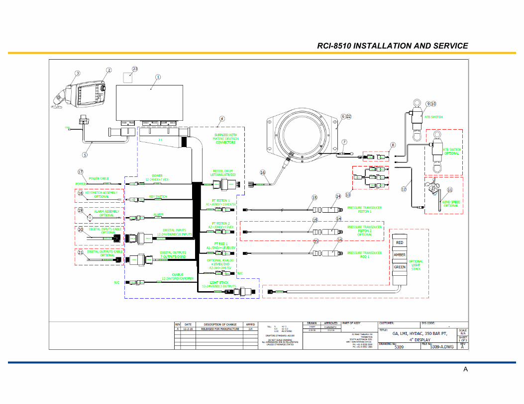
RCI-8510 INSTALLATION AND SERVICE
A
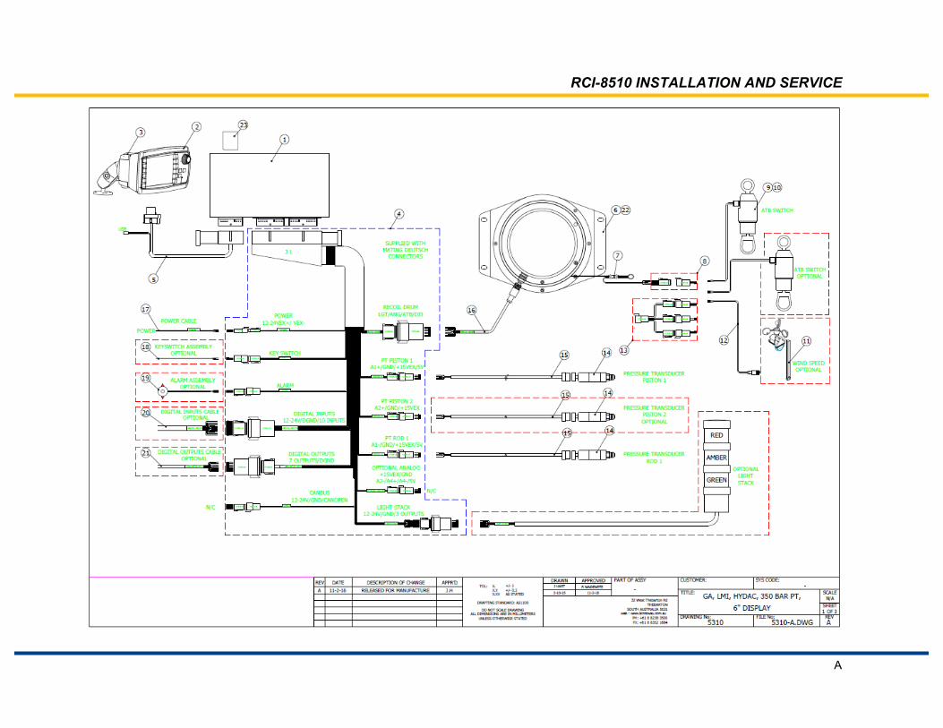
RCI-8510 INSTALLATION AND SERVICE
A
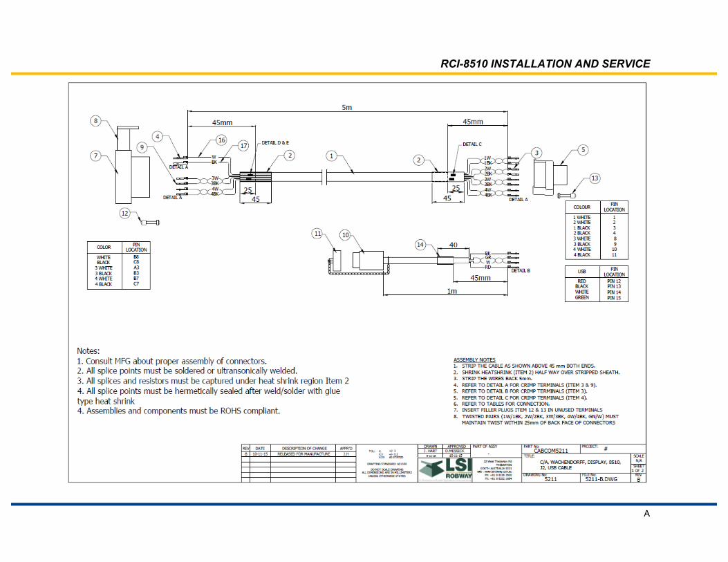
RCI-8510 INSTALLATION AND SERVICE
A
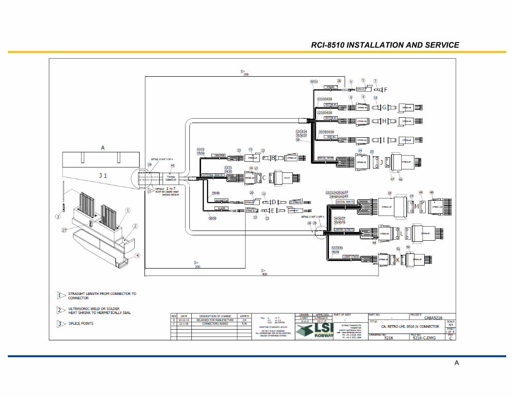
RCI-8510 INSTALLATION AND SERVICE
A

RCI-8510 INSTALLATION AND SERVICE
A

RCI-8510 INSTALLATION AND SERVICE
A

RCI-8510 INSTALLATION AND SERVICE
A
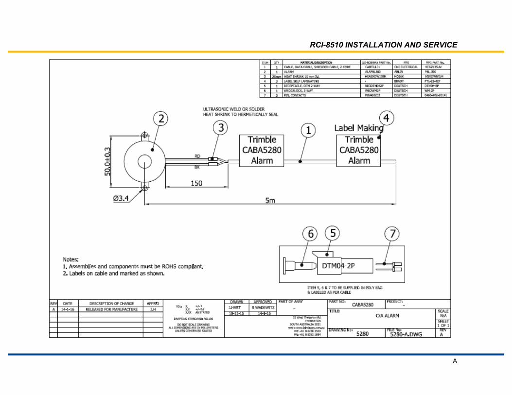
RCI-8510 INSTALLATION AND SERVICE
A

RCI-8510 INSTALLATION AND SERVICE
A

RCI-8510 INSTALLATION AND SERVICE
A

RCI-8510 INSTALLATION AND SERVICE
A

RCI-8510 INSTALLATION AND SERVICE
A
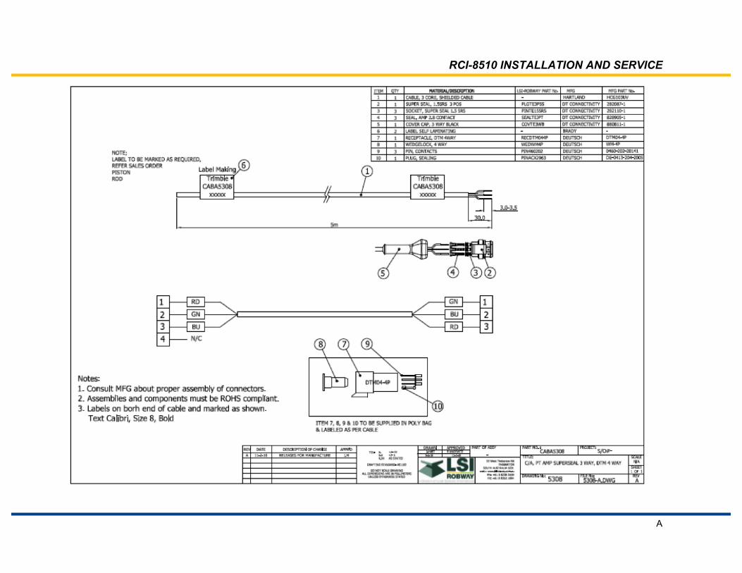
RCI-8510 INSTALLATION AND SERVICE
A

RCI-8510 INSTALLATION AND SERVICE
B
Appendix B: Duty Listing
Duty Listing can be found in the pocket on the back cover.

RCI-8510 INSTALLATION AND SERVICE
C
Appendix C: Software Configuration
Software Documents can be found in the pocket on the back cover.

RCI-8510 INSTALLATION AND SERVICE
D
Appendix D: Component Drawings
The following are dimensional Drawings of typical components supplied with RCI-8510 systems.
The supplied system may not have all of these components.

RCI-8510 INSTALLATION AND SERVICE
D
RCI-8510 INSTALLATION AND SERVICE
D

RCI-8510 INSTALLATION AND SERVICE
D

RCI-8510 INSTALLATION AND SERVICE
D

RCI-8510 INSTALLATION AND SERVICE
D

RCI-8510 INSTALLATION AND SERVICE
D
RCI-8510 INSTALLATION AND SERVICE
D
Display RAM Bracket Mounting Dimensions
RCI-8510 INSTALLATION AND SERVICE
D
RCI-8510 CONTROLLER DIMENSIONS

RCI-8510 INSTALLATION AND SERVICE
D

RCI-8510 INSTALLATION AND SERVICE
D

RCI-8510 INSTALLATION AND SERVICE
D

RCI-8510 INSTALLATION AND SERVICE
D

RCI-8510 INSTALLATION AND SERVICE
D

RCI-8510 INSTALLATION AND SERVICE
D

RCI-8510 INSTALLATION AND SERVICE
D

© 2016, Trimble Lifting Solutions
www.trimble.com/liftingsolutions
Technical support is available 24 hours a day, 7 days a week
[email protected] AMERICAS [email protected]
USA 9633 Zaka Road Houston, TX 77064 Toll Free Tel: +1.888.819.4355 Toll Free Fax: +1.888.238.4099 Tel: +1.281.664.1330 Fax: +1.281.664.1390
EUROPE | MIDDLE EAST | AFRICA [email protected]
UK Unit 3, Kirkhill Place Kirkhill Industrial Place, Dyce Aberdeen AB21 0GU Scotland, UK Tel: +44 (0) 1224.392900 Fax: +44 (0) 1224.392920
CANADA PRODUCTION AND R&D 2666 boul. du Parc Technologique Suite 190 Quebec City, QC G1P 4S6, Canada DUBAI – UAE Q3-171 SAIF Zone PO Box 7976 Sharjah, UAE Tel: 971.6.557.8314 Fax: 971.6.557.8315
AUSTRALIA | NEW ZEALAND ASIA PACIFIC [email protected]
AUSTRALIA 32 West Thebarton Road Thebarton, SA 5031, Australia Tel: +61 (0) 8.8238.3500 Fax: +61 (0) 8.8352.1684