reactive power regulator operation instructions ...€¦ · condensomatic cr2020 operation...
TRANSCRIPT
1
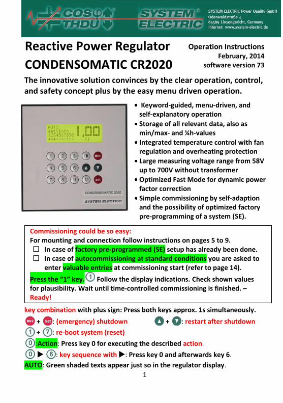
Reactive Power Regulator
CONDENSOMATIC CR2020
Operation Instructions February, 2014
software version 73
The innovative solution convinces by the clear operation, control, and safety concept plus by the easy menu driven operation.
Keyword-guided, menu-driven, and self-explanatory operation
Storage of all relevant data, also as min/max- and ¼h-values
Integrated temperature control with fan regulation and overheating protection
Large measuring voltage range from 58V up to 700V without transformer
Optimized Fast Mode for dynamic power factor correction
Simple commissioning by self-adaption and the possibility of optimized factory pre-programming of a system (SE).
key combination with plus sign: Press both keys approx. 1s simultaneously.
+ : (emergency) shutdown + : restart after shutdown
+ : re-boot system (reset)
:Action: Press key 0 for executing the described action.
: key sequence with : Press key 0 and afterwards key 6.
AUTO: Green shaded texts appear just so in the regulator display.
Commissioning could be so easy: For mounting and connection follow instructions on pages 5 to 9. In case of factory pre-programmed (SE) setup has already been done. In case of autocommissioning at standard conditions you are asked to
enter valuable entries at commissioning start (refer to page 14).
Press the “1” key. Follow the display indications. Check shown values for plausibility. Wait until time-controlled commissioning is finished. – Ready!

2
Operation Instructions – Table of Contents
Display and Operation Elements, Rapid Commissioning ........................... 3
1. What does the CR2020 distinguish? ...................................................... 4
2. Mounting and Connection Safety Instructions ........................................ 5 Mounting; Technical Data; Variants; Modifications .................................... 6, 7
Resolution of the System by C/k or Qmin; Wiring Diagram .................... 8, 9
3. Menu Navigation – comparable to usage of mobiles ........................... 10
4. Test Outputs (functional check of the system configuration) ...................... 12
5. Autostart and Commissioning Menu ................................................... 13 Preconditions for Automatic Commissioning; 1:autostart ........................... 13 Automatic Mode (AUTO); What to do after commissioning failed? ............ 14 What to consider for commissioning? 0:Commissioning Menu ..............14, 15
6. Menu Preprogramming SE ......................................................................... 16
7. Resolving Problems during commissioning – 2:experts menu ............ 17
8. Automatic Control (AUTO): standardwindow1 / 2 ............................. 19
9. 0:main manu – keyword-guided, self-explaining ................................ 21 1:standardwindow 1 / 2; 2:new alarms ...................................... 21 3:readings (actual and 0.25h based values) ........................................ 21 4:min/max readings (peak and 0.25h based values) .......................... 22 5:step information; 6:alarms (AL) ............................................... 22 Explanations to Alarms; AL Display Indication ............................ 23 – 25 Alarm Notices; Alarm Switchoff; Alarm Thresholds .................... 25 – 27 7:manual mode (MAN) .................................................................... 27 8:setup .............................................................................................. 28 9:service menu; Password / Data Security................................ 31, 32
10. Hardware: Temperature Sensor; Alarm Relay; Interface RS485 ......... 33, 34
11. Special Features: Aids for Net Analysis; Target Range cos ............. 34, 35 Low Load; Harmonic Alarms; Combi Detuning; Absorption Circuit .............35 Dynamical Systems; Half-Dynamical Systems; Contactor Operation ......... 36 Programmed Basic Load; Fault Analysis; Inductive Steps ...................... 36, 37 Overloaded Current Transducer; Maintenance; Reparation .................. 37, 38
12. Troubleshooting .................................................................................. 38
For set or change of target-cos and target-cos range ........................... 28
3
Display and Operation Elements
4-lines LCD display and overall 15 numerical buttons or function keys
– Keys for menu navigation // numerical entry
, Keys scroll between menu windows // show important set values and readings when called up from the standardwindow
Key allows returning into the next higher menu level // aborts the commissioning or an input
Key starts or confirms data input // opens the info menu when called up from the standardwindow
Key for contrast adjustment of the LCD-display
Rapid Commissioning – follow advices in the display
1. For mounting and connection follow instructions on pages 5 to 9.
2. Commisioning: 1:autostart: Press the "1" key . In case of
factory pre-programmed (SE) proceed with item 3.
autocommissioning at standard conditions: You will be asked to enter some parameters that the regulator cannot determine itself (not required at rerun commissioning, the regulator remembers your last entry): Enter 1:transducer , 3:detuning factor , and as
desired 2:password . Back to commissioning using . If standard parameters do not match system requirements, use first
set:change standard . By 1:config. data frequently used and by 2:setup all parameters can be changed (refer to pages 28 - 30). For help or tests use 3:info + tests . Go back to autostart by pressing
several times. 1:autostart starts autocommissioning.
3. Wait until finishing time-controlled commissioning. Check shown values for plausibility. – Ready.
4. On troubles repeat autocommissioning or use 2:experts menu for entering net-configuration and step power (refer to pages 17 - 18).
Warning: After completion of the autocommissioning the regulator changes into the Automatic Control Mode (AUTO).
4
1. What does the CR2020 distinguish?
Commissioning:
net-configuration: automatic detection of the phase-to-pin connection for measuring voltage and measuring current
Both capacitive and inductive step powers are automatically sized. Only inductive steps have to be labelled before autostart.
Autocommissioning is possible, even if none load is in use.
factory pre-programmed (SE): straightforward commissioning. Step powers and detuning factor(s) have been pre-programmed by the manufacturer; net-configuration, mains voltage, and current transducer ratio are determined. Pre-programmed step power values are checked. None additional input is necessary.
experts menu: System data such as net-configuration and step powers (also inductive ones) can be entered as values.
Reporting problems regarding the current transducer and facing the raw readings Um, Im, and f at the contact bank for control.
Innovative operation-, control- and safety-concepts:
Optimized load-dependent control modes and the target range cos extend the longevity of the system and reduce the number of switching cycles as well as the net repercussions.
Pressing , in the standardwindow 1 or 2 provides quick information about all important parameters and readings.
alarm notice: service information or shut-down of single steps
alarm switchoff: for special net- or system-disturbances
fault analysis: switchoff of steps for critical power loss (default setting > 20%). An incorrect fault analysis is avoided for unsuccessfully determinable step power under disturbed net-conditions.
password: security against unauthorized access
All changes done on parameters with respect to their standard values are tabulated within the maintenance menu.
The fast algorithm for dynamic compensation reacts on reactive power changes in network within 13ms (control signal to thyristor).
5
Forward-looking operation control and information concept:
Starting from 0:main menu all parameters and readings are quickly available or adjustable using the keyword-guided menu structure and the comfortable keyboard – comparable to the usage of mobiles.
To all relevant net- and system-readings there also exist quarterly averaged as well as min/max readings.
long term means show actual ¼ h, 1 h, 4 h, daily, weekly, monthly,
and yearly means for cos , reactive power (Q), and the missing
reactive power (Qmiss calculated to target cos
display actual and maximum harmonic content of the 2nd - 31th harmonics for voltage U in [%] and current I in [A].
calculated effective current per step (I at step) and do a security shutdown of discrete steps at unallowable harmonic overcurrents
maintenance / reparation menus simplify purposeful servicing
Regulator settings can be stored or recalled as well as reset to default values (system data are preserved) or factory defaults.
programmable basic load e.g. for fix compensation of a transformer
operation contactors: Either several steps operate all together at a single blow for fast net-unloading or subsequently in a cascade for soft-switching repercussions (default setting).
huge range for measuring voltage 58 - 700V AC without transducer
fan switch-off on fast temperature rise or exceeding 15°C beyond excess temperature
2. Mounting and Connection
Safety Instructions
Skilled technical staff is only permitted to mount, connect and commis-
sion the reactive power regulator considering all relevant regulations.
In case of visible or assumable damages the regulator must not be
operated. Only the manufacturer is allowed to repair.
The regulator is energized and must not be opened. Please note that
the clamps can be energized although the regulator is off.
6
Mounting Mount a class 1 transducer, preferentially … / 5A. For its efficiency analysis
(VA), cable length, its cross section, and other in series connected measuring instruments have to be considered.
Warning: The current transducer has to be mounted in the supply line of that part, which should be compensated, and in front of all loads and the connection point of the compensation system!
The temperature sensor sticks approx. 1mm out of the rear side of the regulator. It must not be depressed or covered.
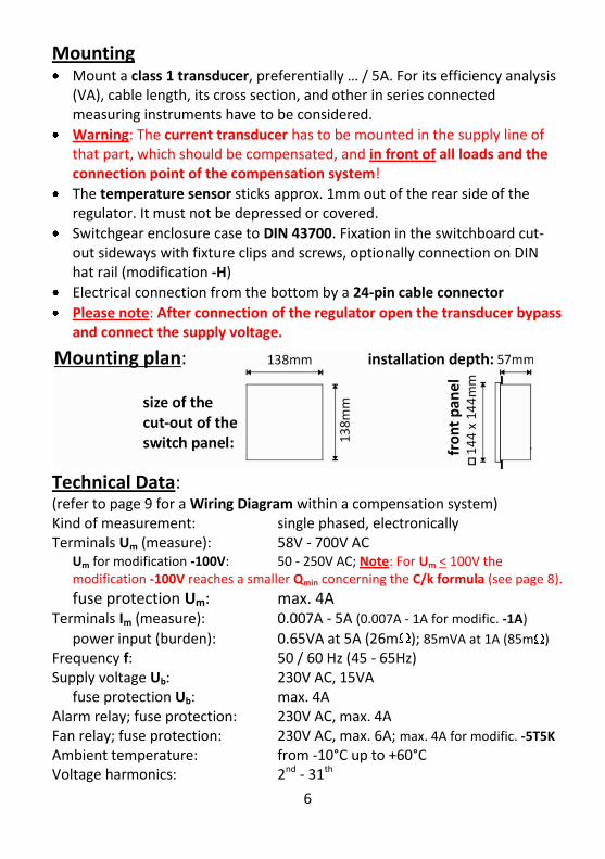
Switchgear enclosure case to DIN 43700. Fixation in the switchboard cut-out sideways with fixture clips and screws, optionally connection on DIN hat rail (modification -H)
Electrical connection from the bottom by a 24-pin cable connector
Please note: After connection of the regulator open the transducer bypass and connect the supply voltage.
Technical Data: (refer to page 9 for a Wiring Diagram within a compensation system) Kind of measurement: single phased, electronically Terminals Um (measure): 58V - 700V AC
Um for modification -100V: 50 - 250V AC; Note: For Um < 100V the modification -100V reaches a smaller Qmin concerning the C/k formula (see page 8).
fuse protection Um: max. 4A Terminals Im (measure): 0.007A - 5A (0.007A - 1A for modific. -1A)
power input (burden): 0.65VA at 5A (26m ); 85mVA at 1A (85m ) Frequency f: 50 / 60 Hz (45 - 65Hz) Supply voltage Ub: 230V AC, 15VA
fuse protection Ub: max. 4A Alarm relay; fuse protection: 230V AC, max. 4A Fan relay; fuse protection: 230V AC, max. 6A; max. 4A for modific. -5T5K Ambient temperature: from -10°C up to +60°C Voltage harmonics: 2nd - 31th

7
Current harmonics: 2nd - 31th Housing, dimensions: protective insulation, 144x144x65mm Ingress protection class: front side IP42 (IP54), rear side IP20
Terminal (24-pin): screw-in connector, protection against direct contact
Variants: n: number of steps (n = 5 or 10)
-K: for contactor switching -T: for thyristor switching
-nK: relay output: 230V (+/- 10%) AC, max. 4A -nT: transistor output: DC 20V at 0mA …5.5V at 150mA
max. 150mA per output, max. 300mA in total
The regulators CONDENSOMATIC CR2020-10T or -5T-5K facilitate the thyristor switches by an internal control voltage. Using CONDENSOTRONIC CT2000 (thyristor switches from SYSTEM ELECTRIC), the regulator's internal mains transformer can only supply a limited number of those thyristor switches:
CR2020 CT2000 per step CT2000 in total
-5T-5K up to 8 up to 20
-10T up to 8 up to 26
If more current should be needed, the regulator variants CR2020-10T-E or CR2020-5T5K-E have to be connected to an external power supply at the terminals X+ and X- (see the wiring diagram on page 9).
For dynamic compensation in Fast-Mode, a control signal is created in 13ms after a fast load change of more than least capacitor power. Using the CONDENSOTRONIC CT2000 thyristor that fact facilitates the compensation capacitor to be effective within 20 – 25msec when prior unloaded. The Fast-Mode can also be switched off. Control signals can already change after only 40msec tracking the network compensation needs.
Smaller or slower load changes are compensated by another algorithm, which can be slowed down correspondingly to an adjustable response time in the range 40 - 10000msec. It defaults to 0ms =off (minimal response time, estimated to be 35msec).
Modifications:
-E: thyristor switch control for use with an external power supply max. output current: 150mA per output and 1.5A in total nominal supply voltage: 12V … 20V DC
internal protection resistor: 47 (transistor switched)
8
-S: Interface:RS485, only instead of the alarm relay (see page 33), available for contactor or thyristor driven systems
-H: housing with DIN rail adapter -100V: For a voltage transformer …/100V the regulator improves its resolution
of the smallest step power Qmin by a factor of 2.7; Um: 50 - 250V AC -1A: For a current transformer …/1A the regulator improves its resolution
of the smallest step power Qmin by a factor of 5; Im: up to 1,3A -Ai: The alarm relay is now working as an opened potential-free contact. -Fm /-Fh: Frequency from measuring voltage Um 190 - 520 V / 420 - 700 V
Resolution of the System by C/k or Qmin
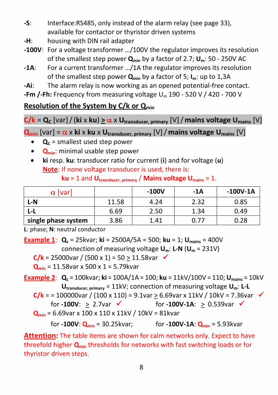
C/k = QC [var] / (ki x ku) > x Utransducer, primary [V] / mains voltage Umains [V]
Qmin [var] = x ki x ku x Utransducer, primary [V] / mains voltage Umains [V] QC = smallest used step power
Qmin: minimal usable step power
ki resp. ku: transducer ratio for current (i) and for voltage (u) Note: If none voltage transducer is used, there is: ku = 1 and Utransducer, primary / Mains voltage Umains = 1.
[var] -100V -1A -100V-1A
L-N 11.58 4.24 2.32 0.85
L-L 6.69 2.50 1.34 0.49
single phase system 3.86 1.41 0.77 0.28 L: phase; N: neutral conductor
Example 1: Qc = 25kvar; ki = 2500A/5A = 500; ku = 1; Umains = 400V connection of measuring voltage Um: L-N (Um = 231V) C/k = 25000var / (500 x 1) = 50 > 11.58var Qmin = 11.58var x 500 x 1 = 5.79kvar
Example 2: Qc = 100kvar; ki = 100A/1A = 100; ku = 11kV/100V = 110; Umains = 10kV Utransducer, primary = 11kV; connection of measuring voltage Um: L-L
C/k = = 100000var / (100 x 110) = 9.1var > 6.69var x 11kV / 10kV = 7.36var for -100V: > 2.7var for -100V-1A: > 0.539var Qmin = 6.69var x 100 x 110 x 11kV / 10kV = 81kvar
for -100V: Qmin = 30.25kvar; for -100V-1A: Qmin = 5.93kvar
Attention: The table items are shown for calm networks only. Expect to have threefold higher Qmin thresholds for networks with fast switching loads or for thyristor driven steps.

9
Wiring Diagram: (drawing also on the regulator's rear side)
1)
CONDENSOMATIC CR2020-… -S: The RS485 interface takes in turn with the alarm relay the terminals X23 / X24 for connection.
fan control at terminals X21 / X22; fuse protection max. 6A, only for CR2020-5T5K max. 4A (protection together with the output relays)
tariff T2 – toggle via potential-free contact at terminals X6 / X7
Regulator Variants:
CONDENSOMATIC CR2020-10K: 10 outputs for contactor-switching (K); joint terminal: X10; switching outputs: terminals from X11 to X20
CONDENSOMATIC CR2020-5T5K or -10T: for dynamic compensation; outputs for thyristor switching (T) at terminals X11 to X15 respectively X20; common +10V= at X10; for CR2020-5T5K switching outputs (K) at terminals X16 to X20 and joint terminal X21 for outputs (K) and fan
CONDENSOMATIC CR2020-5T5K-E or -10T-E: The outputs for thyristor switching (T) are energized by an external power supply at X- and X+.

10
3. Menu Navigation – comparable to usage of mobiles
The reactive power regulator has keyword-guided menu navigation. Thus it is capable to be operated without the operation instructions.
Use 0:main menu to change from any window into the main menu that forms the top layer of the menu branching structure.
From the main menu you can access any information or setup any parameter via a submenu tree structure. Intuitively follow the appro-priate topic. The keyword-guided path can span several submenu levels.
Example showing the paths beginning at the standardwindow 1 / 2 due to read the stored step powers by entering the appropriate key input. Arrows indicate possible transits from one window to another as initiated by key entry or by timeout. The taken action is denoted besides the arrows and described in the menus (also refer to page 19).
The windows of a particular submenu are arranged in a ring. The first line of the actual window contains the path to it or its headline. Use the arrow keys to scroll among the windows. Slowly alternating text blocks within a single window form correspondingly joined texts lines.
During automatic mode (AUTO) the selected standardwindow shows the actual switching and control statuses, too. After 3 minutes without key stroke, the menu automatically changes to the current standard-window (for info on standardwindow 1 or 2 refer to pages 19 - 20).
11
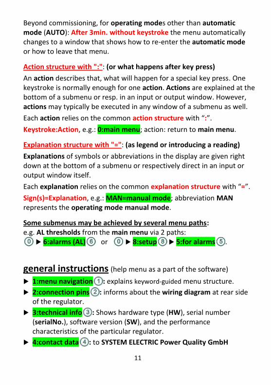
Beyond commissioning, for operating modes other than automatic mode (AUTO): After 3min. without keystroke the menu automatically changes to a window that shows how to re-enter the automatic mode or how to leave that menu.
Action structure with ":": (or what happens after key press)
An action describes that, what will happen for a special key press. One keystroke is normally enough for one action. Actions are explained at the bottom of a submenu or resp. in an input or output window. However, actions may typically be executed in any window of a submenu as well.
Each action relies on the common action structure with “:”.
Keystroke:Action, e.g.: 0:main menu; action: return to main menu.
Explanation structure with "=": (as legend or introducing a reading)
Explanations of symbols or abbreviations in the display are given right down at the bottom of a submenu or respectively direct in an input or output window itself.
Each explanation relies on the common explanation structure with “=”.
Sign(s)=Explanation, e.g.: MAN=manual mode; abbreviation MAN represents the operating mode manual mode.
Some submenus may be achieved by several menu paths: e.g. AL thresholds from the main menu via 2 paths:
6:alarms (AL) or 8:setup 5:for alarms .
general instructions (help menu as a part of the software)
1:menu navigation : explains keyword-guided menu structure.
2:connection pins : informs about the wiring diagram at rear side of the regulator.
3:technical info : Shows hardware type (HW), serial number (serialNo.), software version (SW), and the performance characteristics of the particular regulator.
4:contact data : to SYSTEM ELECTRIC Power Quality GmbH

12
international physical abbreviations with [physical units]: U [V] = voltage; I [A] = current; f [Hz] = frequency S [kVA] = apparent power; P [kW] = active power Q [kvar] = reactive power THDU [%] = percentage of harmonics power in relation to the
fundamental (THD: Total Harmonic Distortion)
combined designators: Urms, Irms = rms-values U resp. I; Umains = mains voltage Im = measuring current, Um = measuring voltage (both without transducer) U1, I1, P, Q = fundamentals share of U [%], I [A], P, Q U2 - U31; I2 - I31 = 2nd - 31th harmonics share U [%], and I [A] Qon = step power switched on – capacitive (+), inductive (-)
Qmiss = reactive power missing to target cos Add-on: .B = basic load-corrected magnitude; then also: .T = reading measured at the current transducer
Alarm designators are listed separately on pages 24 – 26.
4. Test Outputs (functional check of the system configuration) Functional check of the system control without system load
Attention: Remove the power fuses prior to test!
1st part: readings for control: Um, Im, and f at the contact bank.
2nd part: The steps will be switched on and off one after another without regard to the idle period. Cycle number (default: 5 cycles) and cycle period (default: 2s on, 2s. off) are configurable.
3rd part: temperature and alarm test: Blow with hot air against the temperature sensor until the condition for switching on the fan will be reached. Then F* is shown and the fan output is switched on. Reaching the system excess temperature, the display shows A! and the alarm relay is switched on. Then an alarm (AL) may occur, too.
Start test outputs while in commissioning:
0:commissioning menu 7:test outputs
Start test outputs while in the automatic mode (AUTO):
9:service menu 5:test outputs

13
5. Autostart and Commissioning Menu Hint: During gauging the net-configuration and sizing the steps powers you display the raw readings Um, Im, and f at the contact bank by typing the arrow down key . Leave window with or with pressing twice. While this feature is used the progress of commissioning holds. Hint: At the end of commissioning valuable entries are shown again toggling with the final entries. It is still possible that the items can be changed.
1:autostart:
During autocommissioning watch the display.
For factory pre-programmed (SE), Press the „1“ key. : Steps powers, detuning factors, and possibly transducers were pre-programmed. Net-configuration and transducer will be gauged and pre-programmed data will be checked. More options: 4:menu pre-progrSE : Use this menu item to verify or to change
the setup; for more information see chapter 6 on page 16. 0:commissioning menu : See on page 15.
For autocommissioning at standard conditions:
a) For a non-standard system: (for example in case of inductive steps) change parameters before starting autocommissioning: set:change standard
1:config. data : fast access to the major parameters concerning commissioning; For submenus see on pages 17 and 18.
2:setup : keyword-guided access to all parameters; For submenus see on pages 28 - 31.
3:info + tests : For submenus see on page 18.
0:commissioning menu : See on page 15.
b) autocommissioning. Press the „1“ key. :
First, the menu valuable entries are shown. Hint: It is strongly recommended to enter transducer and detuning factor even though these values aren't necessary for the correct compensation.
14
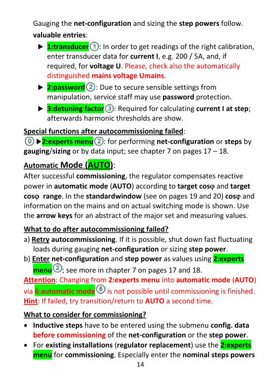
Gauging the net-configuration and sizing the step powers follow.
valuable entries:
1: transducer : In order to get readings of the right calibration, enter transducer data for current I, e.g. 200 / 5A, and, if required, for voltage U. Please, check also the automatically distinguished mains voltage Umains.
2: password : Due to secure sensible settings from manipulation, service staff may use password protection.
3: detuning factor : Required for calculating current I at step; afterwards harmonic thresholds are show.
Special functions after autocommissioning failed:
2:experts menu : for performing net-configuration or steps by gauging/sizing or by data input; see chapter 7 on pages 17 – 18.
Automatic Mode (AUTO): After successful commissioning, the regulator compensates reactive
power in automatic mode (AUTO) according to target cos and target
cos range. In the standardwindow (see on pages 19 and 20) cos and information on the mains and on actual switching mode is shown. Use the arrow keys for an abstract of the major set and measuring values.
What to do after autocommissioning failed?
a) Retry autocommissioning. If it is possible, shut down fast fluctuating loads during gauging net-configuration or sizing step power.
b) Enter net-configuration and step power as values using 2:experts
menu ; see more in chapter 7 on pages 17 and 18. Attention: Changing from 2:experts menu into automatic mode (AUTO)
via 6:automatic mode is not possible until commissioning is finished. Hint: If failed, try transition/return to AUTO a second time.
What to consider for commissioning?
Inductive steps have to be entered using the submenu config. data before commissioning of the net-configuration or the step power.
For existing installations (regulator replacement) use the 2:experts menu for commissioning. Especially enter the nominal steps powers
15
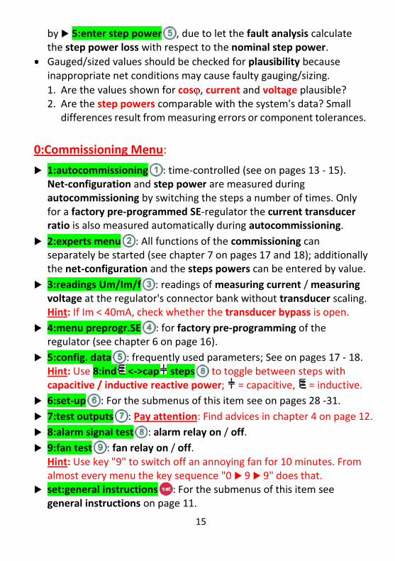
by 5:enter step power , due to let the fault analysis calculate the step power loss with respect to the nominal step power.
Gauged/sized values should be checked for plausibility because inappropriate net conditions may cause faulty gauging/sizing.
1. Are the values shown for cos , current and voltage plausible? 2. Are the step powers comparable with the system's data? Small
differences result from measuring errors or component tolerances.
0:Commissioning Menu:
1:autocommissioning : time-controlled (see on pages 13 - 15). Net-configuration and step power are measured during autocommissioning by switching the steps a number of times. Only for a factory pre-programmed SE-regulator the current transducer ratio is also measured automatically during autocommissioning.
2:experts menu : All functions of the commissioning can separately be started (see chapter 7 on pages 17 and 18); additionally the net-configuration and the steps powers can be entered by value.
3:readings Um/Im/f : readings of measuring current / measuring voltage at the regulator's connector bank without transducer scaling.
Hint: If Im < 40mA, check whether the transducer bypass is open.
4:menu preprogr.SE : for factory pre-programming of the regulator (see chapter 6 on page 16).
5:config. data : frequently used parameters; See on pages 17 - 18. Hint: Use 8:ind <->cap steps to toggle between steps with
capacitive / inductive reactive power; = capacitive, = inductive.
6:set-up : For the submenus of this item see on pages 28 -31.
7:test outputs : Pay attention: Find advices in chapter 4 on page 12.
8:alarm signal test : alarm relay on / off.
9:fan test : fan relay on / off. Hint: Use key "9" to switch off an annoying fan for 10 minutes. From
almost every menu the key sequence "0 9 9" does that. set:general instructions : For the submenus of this item see
general instructions on page 11.
16
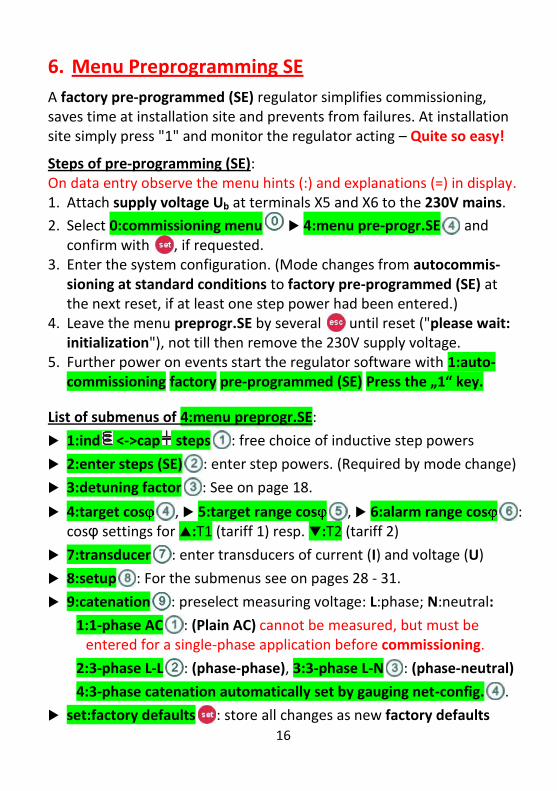
6. Menu Preprogramming SE
A factory pre-programmed (SE) regulator simplifies commissioning, saves time at installation site and prevents from failures. At installation site simply press "1" and monitor the regulator acting – Quite so easy!
Steps of pre-programming (SE): On data entry observe the menu hints (:) and explanations (=) in display. 1. Attach supply voltage Ub at terminals X5 and X6 to the 230V mains.
2. Select 0:commissioning menu 4:menu pre-progr.SE and confirm with , if requested.
3. Enter the system configuration. (Mode changes from autocommis-sioning at standard conditions to factory pre-programmed (SE) at the next reset, if at least one step power had been entered.)
4. Leave the menu preprogr.SE by several until reset ("please wait: initialization"), not till then remove the 230V supply voltage.
5. Further power on events start the regulator software with 1:auto-commissioning factory pre-programmed (SE) Press the „1“ key.
List of submenus of 4:menu preprogr.SE:
1:ind <->cap steps : free choice of inductive step powers
2:enter steps (SE) : enter step powers. (Required by mode change)
3:detuning factor : See on page 18.
4:target cos , 5:target range cos , 6:alarm range cos : cosφ settings for :T1 (tariff 1) resp. :T2 (tariff 2)
7:transducer : enter transducers of current (I) and voltage (U)
8:setup : For the submenus see on pages 28 - 31.
9:catenation : preselect measuring voltage: L:phase; N:neutral:
1:1-phase AC : (Plain AC) cannot be measured, but must be entered for a single-phase application before commissioning.
2:3-phase L-L : (phase-phase), 3:3-phase L-N : (phase-neutral)
4:3-phase catenation automatically set by gauging net-config. .
set:factory defaults : store all changes as new factory defaults

17
7. Resolving Problems during commissioning – 2:experts menu
By the experts menu you are able to successively perform the particular commissioning steps by gauging / sizing or by data input.
Attention: Please observe the instructions shown in the display. The experts menu cancels the factory pre-programmed mode (SE).
1:valuable entries : 1:transducer ; 2:password ; 3:detuning factor ; see explanations on page 13.
2:gauge net-config. : gauging phase angles of measuring voltage Um, e.g. L1-N, and of measuring current Im, e.g. L1, k-l, like in auto-commissioning; also rates mains voltage and mains frequency
Please check: Are the cos value and the mains voltage plausible?
3:enter net-config. : enter net-configuration by value, such as described above for 2:gauge net-config.; Checks are the same.
4:size step power : sizing the steps powers like in autocommissio-ning. The step power is extrapolated to mains voltage due to eliminate effects from fluctuating actual voltages. If the transducer data have not been entered, result values are shown without scaling.
Please, check the sized steps powers. Then enter/check the detuning factor(s). Control the thresholds of THDU / single harmonics alarms, but do not change them unless an expert has cleared the net facts.
5:enter step power : enter the steps powers by value, start with 1:start input . Note: transducer data, net-configuration, and (mostly automatically assigned) mains voltage Umains are required.
Important: Also enter the detuning factor(s). Checks: see item 4.
Hint: Use 2:ind <->cap steps to toggle between steps with capacitive / inductive power; = capacitor step; = reactor step.
6:automatic mode : transition / return to the automatic mode (AUTO). Preconditions: sized / entered net-configuration, mains voltage and step power. It is recommended to enter transducer data and detuning factor(s) before commissioning is left.
Hint: If transition to AUTO failed, try once more.
18
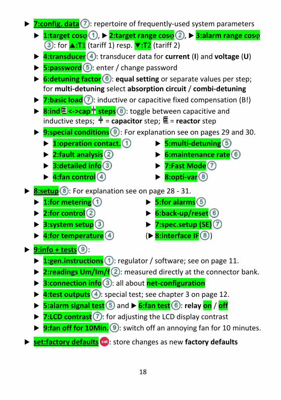
7:config. data : repertoire of frequently-used system parameters
1:target cos , 2:target range cos , 3:alarm range cos: for :T1 (tariff 1) resp. :T2 (tariff 2)
4:transducer : transducer data for current (I) and voltage (U)
5:password : enter / change password
6:detuning factor : equal setting or separate values per step; for multi-detuning select absorption circuit / combi-detuning
7:basic load : inductive or capacitive fixed compensation (B!)
8:ind <->cap steps : toggle between capacitive and inductive steps; = capacitor step; = reactor step
9:special conditions : For explanation see on pages 29 and 30.
1:operation contact.
2:fault analysis
3:detailed info
4:fan control
5:multi-detuning
6:maintenance rate
7:Fast Mode
8:opti-var
8:setup : For explanation see on page 28 - 31.
1:for metering
2:for control
3:system setup
4:for temperature
5:for alarms
6:back-up/reset
7:spec.setup (SE)
(8:interface IF )
9:info + tests :
1:gen.instructions : regulator / software; see on page 11.
2:readings Um/Im/f : measured directly at the connector bank.
3:connection info : all about net-configuration
4:test outputs : special test; see chapter 3 on page 12.
5:alarm signal test and 6:fan test : relay on / off
7:LCD contrast : for adjusting the LCD display contrast
9:fan off for 10Min. : switch off an annoying fan for 10 minutes.
set:factory defaults : store changes as new factory defaults
19
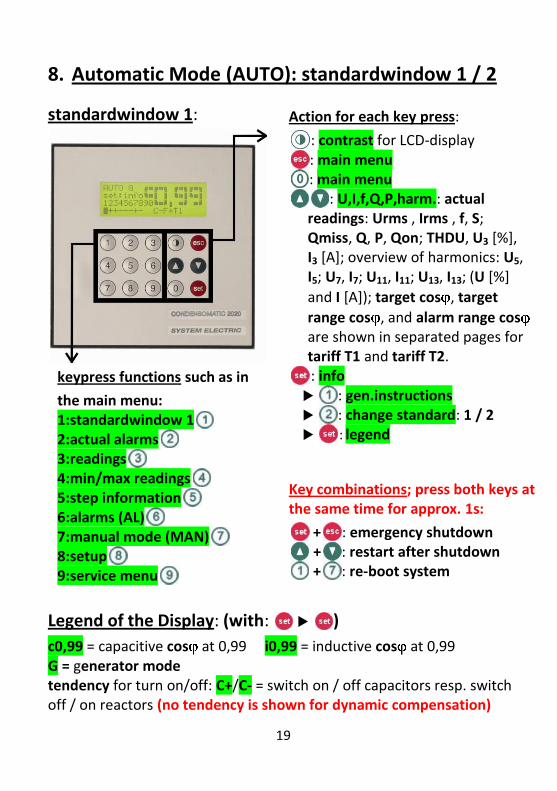
8. Automatic Mode (AUTO): standardwindow 1 / 2
standardwindow 1:
keypress functions such as in
the main menu: 1:standardwindow 1 2:actual alarms 3:readings 4:min/max readings 5:step information 6:alarms (AL) 7:manual mode (MAN) 8:setup 9:service menu
Action for each key press:
: contrast for LCD-display : main menu : main menu
: U,I,f,Q,P,harm.: actual readings: Urms , Irms , f, S; Qmiss, Q, P, Qon; THDU, U3 [%], I3 [A]; overview of harmonics: U5, I5; U7, I7; U11, I11; U13, I13; (U [%]
and I [A]); target cos , target
range cos , and alarm range cos are shown in separated pages for tariff T1 and tariff T2. : info : gen.instructions : change standard: 1 / 2 : legend
Key combinations; press both keys at the same time for approx. 1s:
+ : emergency shutdown + : restart after shutdown + : re-boot system
Legend of the Display: (with: )
c0,99 = capacitive cos at 0,99 i0,99 = inductive cos at 0,99 G = generator mode tendency for turn on/off: C+/C- = switch on / off capacitors resp. switch off / on reactors (no tendency is shown for dynamic compensation)
20
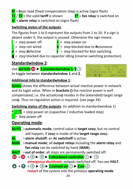
B! = basic load (fixed compensation step) is active (signs flash) T1 / T2 = the valid tariff is shown F* = fan relay is switched on A! = alarm relay is switched on (signs flash)
Switching status of the outputs:
The figures from 1 to 0 represent the outputs from 1 to 10. If a sign is absent under it, the output is unused. Otherwise the sign means: - = step power off + = step power on = step not wired R = step blocked due to Resonance d = step defective t = step blocked for test switching
= step blocked due to capacitor idling (reverse switching protection)
Standardwindow 2:
Use set:info 1:standardwindow 1/2 to toggle between standardwindow 1 and 2.
Additional info to standardwindow 1:
Qmiss shows the difference between actual reactive power in network and its taget value. When in brackets () the reactive power is well compensated, i.e. the actualcosφ resides in the (extended) target range cosφ. Thus no regulation action is required. (see page 34)
Switching status of the outputs: (in addition to standardwindow 1)
/ = step power on (capacitive / inductive loaded step) … = step power off
Operating mode:
AUTO = automatic mode; control value is target cos , but no control
will happen, if cos is inside of the target range cos . AL = alarm shutoff; an AL switchoff is active. MAN = manual mode; all output relays including the alarm relay and
fan relay can be switched by hand (MAN). HALT = out of order; all steps are permanently switched off.
+ = 1:shutdown controller : emergency shutdown; outputs switched off. You see HALT.
+ = 1:system on 2:on : restart of the system into the previous operating mode
21
9. 0:main menu – keyword-guided, self-explaining
The main menu forms the highest level of the keyword-guided menu, and self-explanatory menu structure
Common Key Entries:
0:main menu : returns to the main menu // for numerical entry : jumps one submenu level up // aborts an input
set:info 1: gen.instructions : for handling (see on page 11) 1:info : additional info to that window (e.g. alarmthresholds)
1:standardwindow 1 / 1:standardwindow 2: show the actual
cosφ and other information on regulator's state such as: state of steps, fan, alarm relay, operational mode, basic load, tariff, and
regulation tendency (10K only). Standardwindow 1: cos in enlarged size. Standardwindow 2: Qmiss shows the uncompensated reactive power with respect to the target cosφ. When in brackets "()" the actual cosφ resides within the (extended) target range cosφ. No regulation action is required (see page 34).
2:new alarms: re-activates the pop-up windows of all alarms that
have not been noticed/acknowledged yet. All alarm windows inform about the number of alarms and offer 1:Info for further information.
3:readings: (actual and 0.25h based values)
At first, the regulator enquires the transducer data in case of missing.
For basic load the texts in brackets are valid for cos , Q, lambda: B = converted to basic load and T = measured at the transducer-I
bold type: part of the name; e.g. cos T: cos as measured at T. italic writing: only a hint; e.g. Qmiss(B) is (always) calculated at B.
1:cos ,lambda : cos .(cos B; cos T), lambda(T)
2:power Q,P,S : Q (Q.B; Q.T); Qmiss(B), Qon; P; S
3:basics U,I,f : Urms, Irms, f
4:U harmonics , 5:I harmonics : actual values of the 2nd - 31th harmonics for voltage U and THDU in [%], and for current harmonics in [A], presented both in figures and graphically
22
6:I at step : calculated real current Irms per step in [A]
7:temperature : actual temperature and daily mean
8:survey : all important set and measuring values
9:long term means : cos (cos .B), Q (Q.B), Qmiss(B) (see p.34)
4:min/max readings: (peak and 0.25h based values)
to like submenus 1 to 7 in 3:readings; within each submenu 7:clear readings: clear only that min/max readings.
8:reset min/max : reset of all min/max readings
5:step information: (please notice 1:info when offered)
1:step power Qc : Left/right value: initially gauged or entered / actual step power Qc in [kvar] resp. step power loss in [%].
(step powers are converted to mains voltage/mains frequency)
2:cycles on/off , 3:operation time : usage information, important for the life time of the contactor / capacitor
4:I at step : calculated real current Irms per step in [A]
5:detuning factor : values shown per step (also if equal setting); shows absorption circuit / combi-detuning on multi-detuning.
6:info per step : all values from to but listed per step
6:alarms (AL):
1:actual alarms : all actual alarms (also acknowledged ones)
2:accumulated AL : List all alarm types (scroll with the arrow keys) with their number of occurrence since last reset / total number in life. 1:info: explanation, 7:*->0 reset that number only.
3:AL thresholds : see page 26 for a list of types and values of the AL thresholds.
1:AL cos : 1:alarm cos T1/T2 ; 2:alarm delay ; 3:low load : behavior when all steps are switched off
2:steps : 1:cycles on/off ; 2:operation time ; 3:step power Qc ; 4:I at step : calculated value; 5:fault analysis : monitoring of the step power
3:harmonics : 1:harmon. THDU ; 2: single harm. Un ; 3: I at step : calculated current Irms [A] per step

23
4:voltage : 1:Umax , and 2:Umin in [%] of Umains
5:temperature : 1:excess temperat. , 2:delay , and 3:hysteresis : AL switchoff for temp. > excess temp.
6:maintenance rate , 7:AL cluster : very special items.
4:alarm signal at… : defines, which alarm releases an external alarm signal. Thus, unwanted external alarms can be avoided.
5:alarm signal test : external alarm signal on / off
6:acoust. alarm : acoustic alarm beeper on / off
Explanations to Alarms (AL): (Insert into 0:main menu)
All alarms are active with the thresholds of the default setting.
alarm switchoff (operating mode AL): All outputs are switched off while the reason for the alarm continues.
Alarms with switchoff (e.g. excess temperature) can also get active during commissioning thereby pausing gauging/seizing.
Alarms with switchoff are delayed in most cases (see on page 26).
After 20-times alarm switchoff or reset occurred without acknowledge by the user, the regulator changes into operating mode HALT and switches off all steps, until HALT is manually left (see on page 20).
alarm notice without switchoff (possibly with single step off): Shows need for action. Anyhow, the compensation algorithm continues.
Use 0:main menu 6:alarms (AL) 4:alarm signal at… : to particularly configure, which alarms should releases an external alarm signal (alarm relay closed). By default all alarms go external.
All AL thresholds can be password-protected except alarm-cos T1/T2 with the alarm delay and low load.
If the software is not able to monitor the step powers, the regulator by itself may turn off fault analysis, issuing AL3 (see page 37).
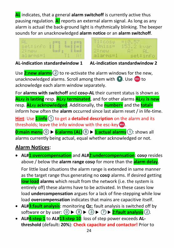
AL Display Indication: (after the alarm pop-up windows disappeared)
Any new alarm is displayed for 3 minutes in an alarm window with an AL description. After that the display returns to the standardwindow with the indication in lines 3/4: 2:new alarms= quantity. Key re-activates that alarm windows. Enter due to get all alarms still actual.
24
AL indicates, that a general alarm switchoff is currently active thus pausing regulation. A! reports an external alarm signal. As long as any alarm is actual the back-ground light is rhythmically blinking. The beeper sounds for an unacknowledged alarm notice or an alarm switchoff.
AL-indication standardwindow 1 AL-indication standardwindow 2
Use 2:new alarms to re-activate the alarm windows for the new, unacknowledged alarms. Scroll among them with . Use to acknowledge each alarm window separately.
For alarms with switchoff and cos -AL their current status is shown as ALxy is lasting resp. ALxy terminated, and for other alarms ALxy is new resp. ALxy acknowledged. Additionally, the number= and the total= inform how often the alarm occurred since last alarm reset / in life-time.
Hint: Use 1:info to get a detailed description on the alarm and its thresholds; leave the info window with the esc-key .
0:main menu 6:alarms (AL) 1:actual alarms : shows all alarms currently being actual, equal whether acknowledged or not.
Alarm Notices:
AL#1:overcompensation and AL#2:undercompensation: cos resides
above / below the alarm range cos for more than the alarm delay.
For little load situations the alarm range is extended in same manner as the target range thus generating no cosφ alarms. If desired getting low load alarms which result from the network (i.e. the system is entirely off) these alarms have to be activated. In these cases low load undercompensation argues for a lack of fine-stepping while low load overcompensation indicates that mains are capacitive itself.
AL#3:fault analysis: monitoring Qc; fault analysis is switched off by software or by user: 2:fault analysis .
AL#4:step 1 to AL#13:step 10: loss of step power exceeds AL-threshold (default: 20%): Check capacitor and contactor! Prior to
25
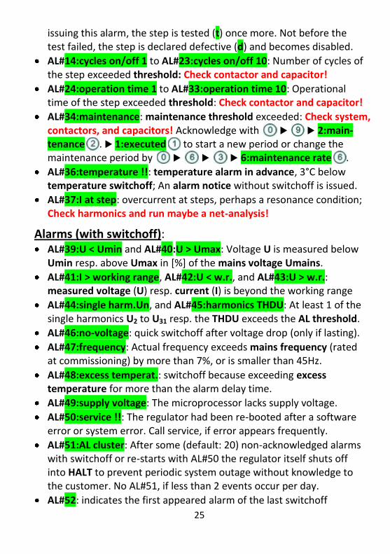
issuing this alarm, the step is tested (t) once more. Not before the test failed, the step is declared defective (d) and becomes disabled.
AL#14:cycles on/off 1 to AL#23:cycles on/off 10: Number of cycles of the step exceeded threshold: Check contactor and capacitor!
AL#24:operation time 1 to AL#33:operation time 10: Operational time of the step exceeded threshold: Check contactor and capacitor!
AL#34:maintenance: maintenance threshold exceeded: Check system, contactors, and capacitors! Acknowledge with 2:main-tenance . 1:executed to start a new period or change the maintenance period by 6:maintenance rate .
AL#36:temperature !!: temperature alarm in advance, 3°C below temperature switchoff; An alarm notice without switchoff is issued.
AL#37:I at step: overcurrent at steps, perhaps a resonance condition; Check harmonics and run maybe a net-analysis!
Alarms (with switchoff): AL#39:U < Umin and AL#40:U > Umax: Voltage U is measured below
Umin resp. above Umax in [%] of the mains voltage Umains.
AL#41:I > working range, AL#42:U < w.r., and AL#43:U > w.r.: measured voltage (U) resp. current (I) is beyond the working range
AL#44:single harm.Un, and AL#45:harmonics THDU: At least 1 of the single harmonics U2 to U31 resp. the THDU exceeds the AL threshold.
AL#46:no-voltage: quick switchoff after voltage drop (only if lasting).
AL#47:frequency: Actual frequency exceeds mains frequency (rated at commissioning) by more than 7%, or is smaller than 45Hz.
AL#48:excess temperat.: switchoff because exceeding excess temperature for more than the alarm delay time.
AL#49:supply voltage: The microprocessor lacks supply voltage.
AL#50:service !!: The regulator had been re-booted after a software error or system error. Call service, if error appears frequently.
AL#51:AL cluster: After some (default: 20) non-acknowledged alarms with switchoff or re-starts with AL#50 the regulator itself shuts off into HALT to prevent periodic system outage without knowledge to the customer. No AL#51, if less than 2 events occur per day.
AL#52: indicates the first appeared alarm of the last switchoff
26
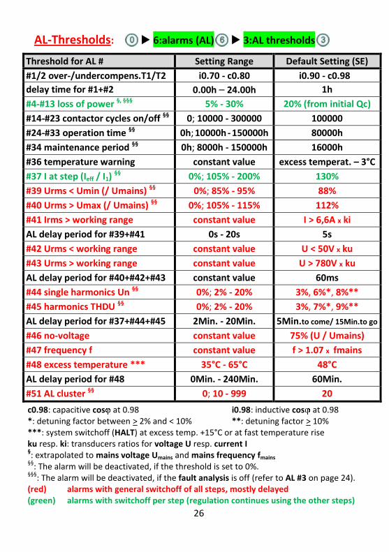
AL-Thresholds: 6:alarms (AL) 3:AL thresholds
Threshold for AL # Setting Range Default Setting (SE)
#1/2 over-/undercompens.T1/T2 i0.70 - c0.80 i0.90 - c0.98
delay time for #1+#2 0.00h – 24.00h 1h
#4-#13 loss of power §, §§§ 5% - 30% 20% (from initial Qc)
#14-#23 contactor cycles on/off §§ 0; 10000 - 300000 100000
#24-#33 operation time §§ 0h; 10000h - 150000h 80000h
#34 maintenance period §§ 0h; 8000h - 150000h 16000h
#36 temperature warning constant value excess temperat. – 3°C
#37 I at step (Ieff / I1) §§ 0%; 105% - 200% 130%
#39 Urms < Umin (/ Umains) §§ 0%; 85% - 95% 88%
#40 Urms > Umax (/ Umains) §§ 0%; 105% - 115% 112%
#41 Irms > working range constant value I > 6,6A x ki
AL delay period for #39+#41 0s - 20s 5s
#42 Urms < working range constant value U < 50V x ku
#43 Urms > working range constant value U > 780V x ku
AL delay period for #40+#42+#43 constant value 60ms
#44 single harmonics Un §§ 0%; 2% - 20% 3%, 6%*, 8%**
#45 harmonics THDU §§ 0%; 2% - 20% 3%, 7%*, 9%**
AL delay period for #37+#44+#45 2Min. - 20Min. 5Min.to come/ 15Min.to go
#46 no-voltage constant value 75% (U / Umains)
#47 frequency f constant value f > 1.07 x fmains
#48 excess temperature *** 35°C - 65°C 48°C
AL delay period for #48 0Min. - 240Min. 60Min.
#51 AL cluster §§ 0; 10 - 999 20
c0.98: capacitive cos at 0.98 i0.98: inductive cos at 0.98 *: detuning factor between > 2% and < 10% **: detuning factor > 10% ***: system switchoff (HALT) at excess temp. +15°C or at fast temperature rise ku resp. ki: transducers ratios for voltage U resp. current I §: extrapolated to mains voltage Umains and mains frequency fmains
§§: The alarm will be deactivated, if the threshold is set to 0%.
§§§: The alarm will be deactivated, if the fault analysis is off (refer to AL #3 on page 24).
(red) alarms with general switchoff of all steps, mostly delayed (green) alarms with switchoff per step (regulation continues using the other steps)
27
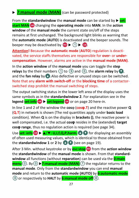
7:manual mode (MAN) (can be password protected)
From the standardwindow the manual mode can be started by set: start MAN changing the operating mode into MAN. In the action window of the manual mode the current state on/off of the steps remains at first unchanged. The background light blinks as warning that the automatic mode (AUTO) is deactivated and the beeper sounds. The beeper may be deactivated by .
Attention! Because the automatic mode (AUTO) regulation is deacti-vated, the service staffs themselves are responsible for over- or under-compensation. However, alarms are active in the manual mode (MAN).
In the action window of the manual mode you can toggle the step relays by the their numbers to and , the alarm relay by , and the fan relay by . Also defective or unused steps can be switched. Note that any alarm with switch-off or the blocking time of a contactor-switched step prohibit the manual switching of steps.
The output switching status in the lower left area of the display uses the same symbols as in the standardwindow 2. For explanation see in the legend set:info set:legend or on page 20 here-in.
In line 1 and 2 of the window the cos (cosφ.T) and the reactive power Q (Q.T) in network is shown (The red quantities apply under basic load condition). When Q is on the display in brackets (), the reactive power is well compensated, i.e. the actual cosφ resides in the (extended) target cosφ range, thus no regulation action is required (see page 34).
Use set: info /: U,I,f,Q,P,harm. for displaying an assembly of often used measuring values, which is identical to those obtained from the standardwindow 1 or 2 by (see on page 19).
After 3 Min. without keystroke or by esc:stop from the action window the standardwindow of the manual mode is shown. From that standard-window all functions (without reparation) can be used via the 0:main menu . By 7:manual mode (MAN) the regulator returns to the manual mode. Only from the standardwindow you can end manual mode and return to the automatic mode (AUTO) by 6:automatic mode
or respectively to HALT by 6:manual mode off .

28
8:setup
Attention! The factory defaults comprise reasonable settings. Only qualified staff may change settings. Respect the performance data of the system's components!
The input menus show the actual setting of the parameter to be changed. During input also its setting range is shown.
1:for metering
Setting Quantity Setting Range Factory Default
1:transducer I 5 - 30000A / 1 or 5A 5 / 5A
2:transducer U 100 - 30000V / 100 - 700V 700 / 700V
3:I-surge dead time : Surge peaks of current Irms beyond the measuring range are suppressed for 5s by default; range: 0 - 20s. Note: This is the alarm delay period for AL#39+#41, too.
4:transd.overcharge : If Irms is greater than the overcharge current, fault analysis / monitoring Qc will be suspended. If 0A (= auto) the regulator did yet not find any transducer overcharge.
5:phase error : balance the phase error of the transducers (6:catenation : visible only at commissioning; see on page 16.)
2:for control
Setting Quantity Range Factory Default
1:target cos i0.70 - c0.80 T1: 1.00 / T2: i0.95
2:target range cos i0.70 - c0.80 T1: i0.95 - 1.00
T2:i0.90 - i0.95
3: alarm range cos i0.70 - c0.80 T1, T2: i0.90 - c0.98
T1/T1 = tariff 1/2; change value by 0.01 using , ; Follow the displayed menus!
4:for contactors : special settings only for contactors 1:response time : 10K: range: 4 - 3600s, default: 15s; the
response time is extended up to 10-times for low demand 5T5K: range: 0; 0.10 - 120s, default: 0s=off (as fast as can be). 2:operation contact. : switch subsequently or all together 3:idle period : range: 3 - 300s, default: 45s. Observe the
capacitor discharging time preventing connection in antiphase.
29
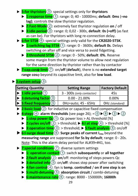
5:for thyristors : special settings only for thyristors 1:response time : range: 0; 40 - 10000ms; default: 0ms (=no
lag); controls the slow thyristor regulation. 2:Fast-Mode : extremely fast thyristor regulation on / off 3:idle period : range: 0; 0,02 - 300s, default: 0s (=off) (as fast
as can be). For thyristors with long re-connection delay. 6:for 5T5K : special settings only valid for the CR2020-5T5K. 1:switching lag 5T5K : range: 0 - 3600s; default 0s. Delays
switching on after off and vice versa to avoid fidgetting. 2:threshold 5T5K : range: 0 - 50%; default: 0%. Reserve
some margin from the thyristor volume to allow next regulation for the same direction by thyristor rather than by contactor
7:cap.cosφ limit : on/off (default), there is no extended target
range cos beyond its capacitive limit, also for low load.
3:system setup :
Setting Quantity Setting Range Factory Default
1:idle period 3 - 300s (only contactor) 45s
3:detuning factor 0.00 - 21.00% 0.00%
5:fixed frequency 0Hz=auto; 45 - 65Hz 0Hz (standard)
2:basic load : for inductive or capacitive fixed compensation 4:steps : alarm thresholds (see page 26); = 1:step power Qc : Qc power loss > AL threshold [%] 2:cycles on/off : > threshold; 4:I at step : > threshold [%] 3:operation time : > threshold; 5:fault analysis : on/off
6:I-surge dead time : Surge peaks of current Irms beyond the measuring range are suppressed for 5s by default; range: 0 - 20s.
Note: This is the alarm delay period for AL#39+#41, too.
7:special conditions : diverse system settings 1: operation contact : switch subsequently or all together 2:fault analysis : on/off: monitoring of steps powers Qc 3:detailed info : on/off: shows step power after switching 4:fan control : fan is temp. controlled / on if one step is on 5:multi-detuning : absorption circuit / combi-detuning 6:maintenance rate : range: 8000 - 150000h; 16000h
30
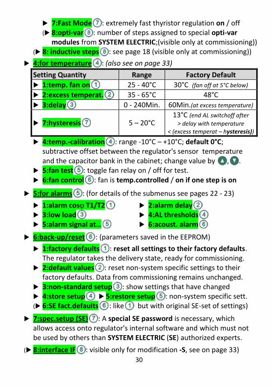
7:Fast Mode : extremely fast thyristor regulation on / off(8:opti-var : number of steps assigned to special opti-var
modules from SYSTEM ELECTRIC;(visible only at commissioning)) (8: inductive steps : see page 18 (visible only at commissioning))
4:for temperature : (also see on page 33)
Setting Quantity Range Factory Default
1:temp. fan on 25 - 40°C 30°C (fan off at 5°C below)
2:excess temperat. 35 - 65°C 48°C
3:delay 0 - 240Min. 60Min.(at excess temperature)
7:hysteresis 5 – 20°C 13°C (end AL switchoff after
> delay with temperature < (excess temperat – hysteresis))
4:temp.-calibration : range -10°C – +10°C; default 0°C; subtractive offset between the regulator's sensor temperature and the capacitor bank in the cabinet; change value by , .
5:fan test : toggle fan relay on / off for test. 6:fan control : fan is temp.controlled / on if one step is on
5:for alarms : (for details of the submenus see pages 22 - 23)
1:alarm cos T1/T2 2:alarm delay 3:low load 4:AL thresholds 5:alarm signal at… 6:acoust. alarm
6:back-up/reset : (parameters saved in the EEPROM)
1:factory defaults : reset all settings to their factory defaults. The regulator takes the delivery state, ready for commissioning.
2:default values : reset non-system specific settings to their factory defaults. Data from commissioning remains unchanged.
3:non-standard setup : show settings that have changed 4:store setup 5:restore setup : non-system specific sett. (6:SE fact.defaults : like but with original SE-set of settings)
7:spec.setup (SE) : A special SE password is necessary, which allows access onto regulator's internal software and which must not be used by others than SYSTEM ELECTRIC (SE) authorized experts.
(8:interface IF : visible only for modification -S, see on page 33)
31
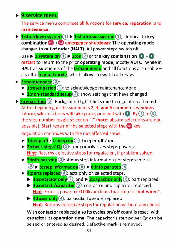
9:service menu
The service menu comprises all functions for service, reparation, and maintenance.
1:shutdown system 1:shutdown system , identical to key combination + emergency shutdown: The operating mode changes to out of order (HALT). All power steps switch off.
Use 1:system on 2:on or the key combination + : restart to return to the prior operating mode, mostly AUTO. While in HALT all submenus of the 0:main menu and all functions are usable – also the manual mode, which allows to switch all relays.
2:maintenance : 1:reset period : to acknowledge maintenance done. 2:non-standard setup : show settings that have changed
3:reparation : Background light blinks due to regulation affected. At the beginning of the submenus 2, 4, and 5 comments windows inform, which actions will take place, proceed with . By to , the step number toggle selection "!" (note: absurd selections are not possible). Start repair of the selected steps with the key.
Regulation continues with the not-affected steps.
1:beep off / 1:beep on : beeper off / on. 2:check steps' Qc : temporarily sizes steps powers. Hint: Returns defective steps for regulation, if problem solved.
3:info per step : shows step information per step; same as
5:step information 6:info per step . 4:parts replaced : acts only on selected steps. 1:contactor only , and 2:capacitor only : part replaced. 3:contact./capacitor : contactor and capacitor replaced.
Hint: Enter a power of 0.00kvar clears that step to "not wired".
4:fuses only : particular fuse are replaced Hint: Returns defective steps for regulation without any check.
With contactor replaced also its cycles on/off count is reset; with capacitor its operation time. The capacitor's step power Qc can be seized or entered as desired. Defective mark is removed.

32
5:add steps : The capacitor's step power Qc can be seized or entered as desired; the detuning factor is inquired afterwards.
6:ends reparation : return to the prior operating mode. After 3 Min. without keypress the reparation standardwindow informs how to leave reparation by menu item 6.
4:connection info : net-configuration, mains/measuring voltage, transducer data, and Um/Im/f measured at the connector bank
5:test outputs : functional check of the system configuration. For more explanation see chapter 4:test outputs on page 12.
6:initiation : changes the operation mode into commissioning (see chapter 5. on pages 13 et sqq.) and enters the commissioning menu (see on page 15). From there, start 1:autocommissioning or only parts via the 2:experts menu.
Warning: Any new commissioning result may also clear other stored data, e.g. new net-configurations determine new mains voltage or new step powers reset stored cycles on/off and operation time.
For maintenance, reparation, or system extension we strictly recommend to use 9:service menu 3:reparation , where you can act on all (but not on net-configurations) like in commissioning
7:password : change password; max. 9 digits; 0 = no password.
8:gen.instructions : General instructions; see on page 11.
9:fan off for 10Min. : switch off an annoying fan for 10 minutes.
Password / Data Integrity
The service staff may limit access to the regulator by setting a password. Then, all AL-thresholds (except for cosφ) or settings by 8:setup can only be changed with that password. However, the readings or settings can always be read. Without that password no change of the operating mode like into/from manual mode is possible.
The password is a number with up to 9 digits. "0"= no password.
33
If you forgot your password, SYSTEM ELECTRIC can send you a special password, which can reset the service password to "0".
When a password protected system had been opened by password it remains opened until the display falls back into the standardwindow (or remains in it) after 3 Min. without keystroke. Due to lock the system at once invoke "change password" without password entry.
Change password:
+) autocommissioning at valuable entries
+) commissioning menu 5:config. data
+) experts menu 7:config. data
+) standardwindow 9:service
10. Hardware
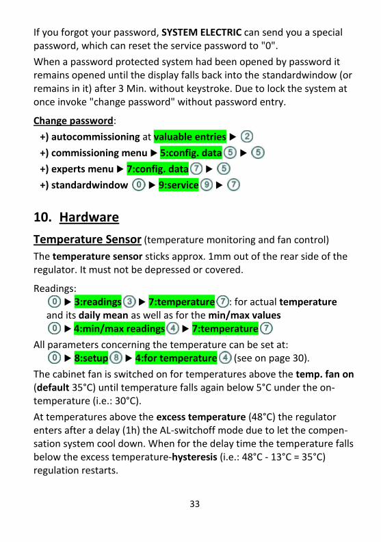
Temperature Sensor (temperature monitoring and fan control)
The temperature sensor sticks approx. 1mm out of the rear side of the regulator. It must not be depressed or covered.
Readings: 3:readings 7:temperature : for actual temperature
and its daily mean as well as for the min/max values 4:min/max readings 7:temperature
All parameters concerning the temperature can be set at: 8:setup 4:for temperature (see on page 30).
The cabinet fan is switched on for temperatures above the temp. fan on (default 35°C) until temperature falls again below 5°C under the on-temperature (i.e.: 30°C).
At temperatures above the excess temperature (48°C) the regulator enters after a delay (1h) the AL-switchoff mode due to let the compen-sation system cool down. When for the delay time the temperature falls below the excess temperature-hysteresis (i.e.: 48°C - 13°C = 35°C) regulation restarts.

34
At a temperature 15°C above the excess temp. or a fast temp. rise the fan is stopped to prevent accelerating fire and the regulator enters the shutdown mode (HALT). User intervention is required for restart.
Alarm Relay
The alarm relay comprises a normally closed potential-free contact. The contact is closed (=alarm), if an active alarm switchoff or an unacknow-ledged alarm notice should be signalled or when regulation is stopped (e.g. not powered during commissioning, shutdown (HALT), or manual mode (MAN); due to allow manual mode to persist beeper off withdraws that alarm). For further description refer to pages 23 - 27. On request SYSTEM ELECTRIC can provide regulators with inverted relay contact.
Interface RS485 (optional, modification identifier -S)
Via the RS485 interface read readings and alarms, or write settings. Configure the interface by menu (only visible, if implemented):
8:setup 8:interface IF : (IF= Interface) Further information on the interface is covered in a special instructions manual for the interface regulator.
11. Special Features
Aids for Net Analysis: (starting from the standardwindow) 3:readings : actual- and 0.25h-based values of all readings: harmonics U and I; actual temperature with daily mean; actual
9:long term means for cos , Q and Qmiss of following periods: 0.25h-, 1h-, 4h-, daily-, weakly-, monthly- and yearly-means 4:min/max readings : extreme values of the same quantities as in 3:readings enclosing 0.25h mean min/max values. 5:step information : see on page 22. 6:alarms (AL) 2:accumulated AL : list of all alarms; the number shows, how often each alarm appeared in the past. 9:service menu 4:connection info : shows net-configuration, mains/measuring voltage, transducer data, and Um/Im/f measured at the connector bank
35
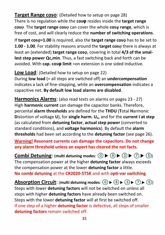
Target Range cos : (Detailed how to setup on page 28)
There is no regulation while the cosφ resides inside the target range
cos The target range cos can cover the whole cos range, which is free of cost, and will clearly reduce the number of switching operations.
If target cos =1.00 is required, also the target range cos has to be set to
1.00 - 1.00. For stability reasons around the target cos there is always at
least an (extended) target range cos , covering in total 4/3 of the smal-lest step power Qc,min. Thus, a fast switching back and forth can be avoided. With cap. cosφ limit =on extension is one sided inductive.
Low Load: (Detailed how to setup on page 22)
During low load (= all steps are switched off) an undercompensation indicates a lack of fine-stepping, while an overcompensation indicates a capacitive net. By default low load alarms are disabled.
Harmonics Alarms: (also read texts on alarms on pages 23 - 27)
High harmonic current can damage the capacitor banks. Therefore, percental alarm thresholds are defined for the THDU (Total Harmonic Distortion of voltage U), for single harm. Un, and for the current I at step (as calculated from detuning factor, actual step power (converted to standard conditions), and voltage harmonics). By default the alarm thresholds had been set according to the detuning factor (see page 26).
Warning! Resonant currents can damage the capacitors. Do not change any alarm threshold unless an expert has cleared the net facts.
Combi Detuning: (multi detuning modes: . )
The compensation power at the higher detuning factor always exceeds the compensation power at the lower detuning factor a little. No combi detuning at the CR2020-5T5K and with opti-var switching.
Absorption Circuit: (multi detuning modes: . )
Steps with lower detuning factors will not be switched on unless all steps with higher detuning factors have already been switched on. Steps with the lower detuning factor will at first be switched off. If one step of a higher detuning factor is defective, all steps of smaller detuning factors remain switched off.
36
Dynamical Systems: Thyristor Switched Compensation: CR2020-10T Thyristors switch capacitors wearlessly, gently, and fast. Capacitors do not need an idle period because switching on with no voltage difference and off at current zero crossing. Preferably, thyristors are used where very fast or frequently cycling is required. Using the thyristor CT2000, the CR2020-10T is able to compensate a load change within about 25msec in Fast Mode; sufficient to keep track on the reactive power of e.g. spot welders.
Half-Dynamical Systems: CR2020-5T5K
The CR2020-5T5K combines the advantages of both thyristor- and contactor-switched steps. While the contactor steps cover the compen-sation of slowly alternating loads, the thyristor steps compensate the fast and frequently fluctuating loads promptly with the Fast Mode. With the right design competitive low compensation systems can be offered.
Contactor Operation: ( )
Contactors switching subsequently (cascade operation) do not issue abrupt load changes in the net; contactors switching all together make fast compensation.
Programmed Basic Load B!: (Fixed Compensation) An additive basic load can be programmed. Due to compensate reactive power at the HV line entry including the mains transformer but still using measurement at the low voltage side program a capacitive basic load compensating the transformers inductive power loss
The standardwindow 1 / 2 show a flashing B! and the cos B value.
cos and Q quantities are suffixed by ".B", when they are related to the extrapolated basic load corrected reference point, and by ".T", when they are related to the real measuring point at the current transducer.
Enter capacitive / inductive basic load by .
Fault Analysis / Monitoring Qc: (Use . )
for on/off) Fault analysis / monitoring Qc check the step powers when they are switched on / off due to recognize the power loss of ageing capacitors. Alarm notices AL#4 to AL#13 will appear, if power loss

37
exceeds a certain AL threshold (default: 20%) and that step is excluded from regulation.
If power measurement is not possible, typically because of fast fluctu-ating loads, the regulator itself can switch off the fault analysis as well as the customer. The alarm notice AL#03 reminds you that fault analysis if off and that you yourself is responsible for system maintenance.
Inductive Steps: (see on pages 18 and 31) The regulator is able to size and to handle inductive steps for compen-sation of capacitive loads or nets. Enter the inductive steps types before commissioning as well as before repair/add steps.
Overloaded Current Transducer: (see on page 28)
A current transducer transforms the current properly, until the secondary overload limits the output current. In that way the regulator is no longer able to determine the step power accurately. A more powerful transducer has to be used or the diameter of the connection line between transducer and regulator must be enlarged. The same behaviour results from other devices connected in series.
Nevertheless, the regulator itself is able to identify such a transducer overload automatically by a special algorithm and suspends the fault analysis for currents greater than an overcharge current. An overcharge current can also be entered by the customer via .
Maintenance: Maintenance Period: (change the rate via . )
After some operation period (default: 16000h= ca.2 years) the regulator reminds by alarm notice AL#34 that you should spend maintenance onto the compensation system (e.g. cleaning from dust, changing fan filters, controlling steps powers, retightening screws, etc.). Acknowledge main-tenance by (restarts maintenance period). Non-Standard Setup: ( ) Shows settings that have changed with respect to the factory defaults. fan off for 10Min.: ( ) Switch off an annoying cabinet fan for about 10 minutes.
38
Reparation: ( ) Using reparation all defective markings can be analyzed and repaired. Also actions typically done during commissioning on all steps can be done on single steps while regulation continues in the background. Actions comprise: 2:check steps' Qc: temporarily sizes steps powers, 4:parts replaced: 1:contactor only, 2:capacitor only, 3:contact.
/capacitor, 4:fuses only; and 5:add steps. (see on page 32)
12. Troubleshooting Problem 1: Autocommissioning was not successful showing a wrong net-configuration or wrong step powers.
Possible Reasons: a) Current transducer short circuit still closed (most likely, if the measuring current Im at contact bank (from commissioning menu 3:readings Um/Im/f ) is smaller than 70mA; b) Current transducer incorrectly connected / overloaded showing less current (see page 37); c) Unsatisfactory net conditions by fast fluctuating loads.
Removal: a) Open current transducer short circuit and check the terminal for contact; b) Use a current transducer with increased power rating or increase cable cross-section considering other equipment in series. Restart commissioning; c) Switch off fast fluctuating loads during commissioning or input net-configuration resp. step powers as values. --------------------------------------------------------------------------------------------------------------------------------
Problem 2: cos is temporarily / always wrong.
Possible Reasons: a) net-configuration falsely gauged / entered; b) current transducer overloaded during heavy load, showing less current.
Removal: a) From AUTO use 4: connection info to show the net-configuration. It can only be changed by commissioning (re-enter from the automatic mode by 9:service 6:initiation ) via 2:experts menu 2:gauge net-config. or 3:enter net-config. . (Return via 6:automatic mode ; repeat on error); b) solve problem with current transducer. Then re-do commissioning. --------------------------------------------------------------------------------------------------------------------------------

39
Problem 3: Steps are not switched on despite of demand.
Possible Reasons: a) you calculated false; b) step power falsely sized; c) Step defective ("t" or "d": shown in the standardwindow 1/2 or in the step power Qc).
Removal: a) Verify that Qmiss in standardwindow 2 is not in brackets; b) Verify steps powers by 1: step power . Note: By standard the actual correct value is used for regulation. c) Replace defective part and use reparation 4:parts replaced for resizing step or inputting step power as a value. --------------------------------------------------------------------------------------------------------------------------------
Problem 4: Fault analysis switches steps off apparently without cause.
Possible Reasons: a) Current transducer overloaded during heavy load thus showing less current; b) Fast fluctuating load impedes correct measurement of step powers during normal operation.
Removal: a) solve problem with current transducer (see Problem 1b); b) Switch off fault analysis / monitoring of step power Qc by
8:special conditions 2:fault analysis .
Note: Remember to periodically control the step powers and check the step status, too! --------------------------------------------------------------------------------------------------------------------------------
Problem 5: AL-switchoff caused by harmonics alarms AL#36, #44, #45.
Possible Reasons: a) Detuning factor is not set; b) Harmonic distortions in the mains are higher than considered by the alarm thresholds.
Removal: a) By 5:detuning factor verify the detuning factors; b) Check the maximum harmonics contributions occurred via
4:min/max readings 4:U harmonics . Do not adjust the alarm thresholds for alarm AL#45:harmonics THDU via 1:harmon.THDU resp. via 2:single harm.Un for AL#44: single harm. Un unless the system components are designed for higher harmonics currents. (Alarms can be disabled by an alarm threshold=0%.) --------------------------------------------------------------------------------------------------------------------------------
Problem 6: Over- or undercompensation alarm (AL#01, AL#02)
Possible Reasons: a) net-configuration falsely gauged / inputted; b) step powers falsely sized / inputted; c) Steps defective;

40
d) On low load (i.e. all steps off): The regulator cannot reach the target
cos range due to a lack of fine stepping, a capacitive net or other capacitive loads.
Removal: a) - c): Like for problems 3 and 4
d) Upgrade system due to improve fine stepping; switch off alarm range
cos of low load via 3:low load (default setting); compensate a capacitive net or load by inductive step power. --------------------------------------------------------------------------------------------------------------------------------
Problem 7: No display content is visible.
Possible Reasons: a) Power supply missing; b) Software crashed. Removal: a) Verify connections; b) Reset software via + . --------------------------------------------------------------------------------------------------------------------------------
Problem 8: Alarm switchoff by AL#47:frequency without cause.
Possible Reason: Automatic frequency tracking is disturbed. Removal: Set value by 5:fixed frequency . --------------------------------------------------------------------------------------------------------------------------------
Problem 9: An alarm switchoff is active.
Possible Reason: The corresponding alarm threshold is exceeded.
Removal: Use 1:Info to get a description to the alarm as well as the AL-threshold. By 4:min/max readings the corresponding extremes and the net-conditions can be checked. Defective components should be replaced. The AL-thresholds may be adjusted with respect to the system parameters and the system components' ratings. --------------------------------------------------------------------------------------------------------------------------------
The regulator still works improperly.
Removal: Contact your service staff or us at SYSTEM ELECTRIC.