real time response to the ... - d'appolonia · pdf filereal time response to the...
TRANSCRIPT
REAL TIME RESPONSE TO THE LANDSLIDE AT THE LEXINGTON APARTMENTS Michael J. Marasa, P.E.1, John R. Wolosick, P.E.2 & Bradley D. Campbell, P.E.3 1 Hayward Baker Inc. (e-mail: [email protected]) 2 Hayward Baker Inc. (e-mail: [email protected]) 3 D’Appolonia (e-mail: [email protected])
Abstract: In late February, 2003, a steep hillside behind three apartment buildings near
Nashville, Tennessee displayed signs of instability. Evidence of movement was noted as small bulges emerged in various places along the slope. In the following days, additional movement was observed and the residents from 70 units were evacuated and relocated.
A geotechnical review confirmed that the physical symptoms were indicative of a landslide. Closer inspection revealed tension cracks developing several hundred feet up the slope and extending laterally approximately 500 feet resulting in an active slide area of about 6 acres with less than 20 feet of clearance between the moving slope and remaining unoccupied apartments.
Data derived from slope inclinometers recorded movements up to 35 feet deep and surveys confirmed that the scarp occurred at least 450 feet up the slope crossing well over the property line. Due to property line constraints, the repair was restricted to the lower half of the active slide area.
As spring rains intensified and the slide movement accelerated, the design-build retention system was converted to a build-design system as the construction moved to a fast-track schedule. An anchored soldier beam and lagging wall was constructed to create the first line of defense.
The permanent repair scheme included an initial installation of the anchored soldier beam and lagging wall augmented by two rows of reaction blocks and anchors located upslope of the wall. As the movement of the slope slowed in response to the initial repairs, some surface grading was performed and surface ditches were constructed to divert surface water from the lower landslide mass to further enhance slide stability.
This paper will cover the emergency action plan, an overview of the design considerations, challenging aspects of the construction and the unique and complicated relationships developed between multiple owners, property managers, designers, peer reviewers, adjacent property owners and the contractor. INTRODUCTION
In 1996, a large parcel of land in Bellevue, Tennessee was investigated for the development of a multi-unit apartment complex. The overall property encompassed approximately 80 acres of moderately to very hilly terrain. The topographic relief in the general vicinity of the development is on the order of 320 feet. The original geotechnical investigation was performed to provide recommendations for foundation design for the structures and included discussions pertaining to retaining walls. During site grading in the fall of 1996, two or three shallow slides occurred behind two of the proposed buildings at the base of the steeper portion of the site. These slides were reportedly repaired by excavation of the loose slide material and replacement with shot rock that was capped with topsoil. After the repairs, building construction resumed and the development was completed in 1998.
1109

In December 2002, the development was sold to an investment firm and a separate property management firm was retained. Following a somewhat wetter than average winter, significant surface bulging and seepage from the slope became apparent. With only fifteen to twenty feet separating the apartments from the toe of the slope, the management staff called for the evacuation of three of the buildings, a total of 70 occupied units. Representatives of the new ownership and management teams convened at the site to interview geotechnical firms and initiated a study. As the study was being completed and the options reviewed, record rainfalls occurred at the site and the slide began a more rapid advancement toward the buildings. On May 11, 2003, the toe of the slide came in contact with one of the buildings. The slope movement cut off all site drainage behind the buildings and many of the ground floor apartments were flooded. A local grading contractor had been on standby and immediately mobilized to begin excavating slide material away from the structures.
Within a few days, the geotechnical contractor was retained to provide a design/build solution, mobilized to the site and began to install soldier piles near the base of the slope as a temporary barrier to protect the structures as the team members brainstormed to determine the composition of the final repair scheme. The detailed design process began a few days following the construction process. As the repair proceeded, the design was constantly altered to adjust to the changing field conditions within the limits of the property.
As the movement of the slide slowed following installation of the soldier beams, other components of the repair could be installed. These included the temporary shot rock buttress, permanent tiebacks for the soldier beam wall, subsurface drainage components at the wall and within the slope, ground anchors and surface drains. Finally, after four months on-site, the remediation was completed and the site cleaned up. The slopes were seeded and strawed, the pavement was repaired in the work area and along the driveways, fences were installed and post-construction monitoring systems were implemented. GEOLOGY
The topographic setting of the Bellevue area of Nashville, Tennessee is represented by undulating hills that occasionally represent significant changes in elevation that are a result of ancient weathering of the geologic profile. Often, the erosion process exposes several formations of different character and composition. In this case, the site is underlain by limestone of the Liepers and Catheys Formations. However, the bad actors are the Fort Payne and Sequatchie Formations that are present at the higher elevations adjacent to the site. Those formations typically weather significantly and produce variable thicknesses of colluvium along the lower portions of slopes. The composition of these gravity-deposited soils generated from the weathering of the upper formations is different than the makeup of the residual soils overlying the Liepers and Catheys Formation. In this region, the colluvium is usually somewhat permeable, contains wide variations in grain size in the soil fraction and often contains numerous rock chips and chert fragments. As a result of their method of deposition, colluvial soils in this setting usually exhibit preferential bedding planes and, therefore, are often pseudo stable. The residual soil above the Liepers and Catheys is usually slightly silty to silty stiff clay with occasional chert fragments. It is not uncommon for a thin zone above bedrock to be water bearing and much softer.
While the weathering of the Sequatchie and Fort Payne Formations produces colluvial soils, its presence is not ubiquitous along the lower slopes. Occasionally, terraces along typically steeper hillsides are a hint of colluvial deposits. However, the soils maps produced by the US
1110
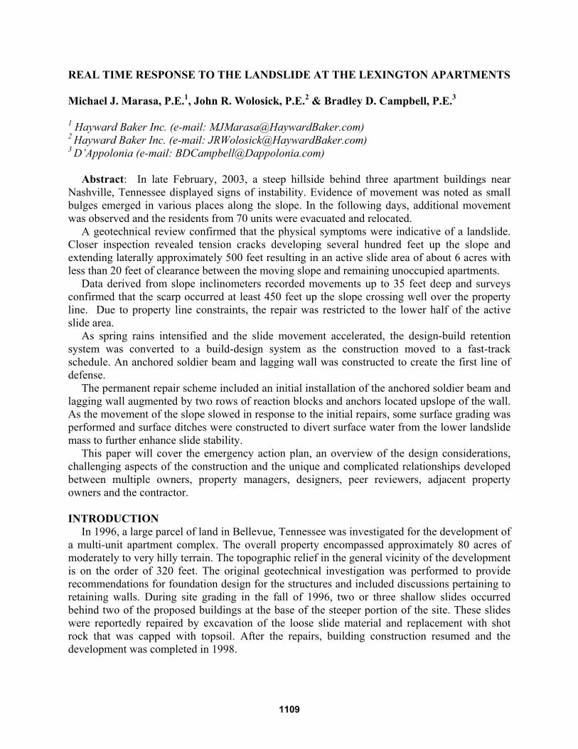
Department of Agriculture are often a very reliable indicator of colluvial soils. In this case, the Dellrose soils contain many of the characteristics of colluvium produced by the geographically higher parent bedrocks. As can be seen in Figure 1, the landslide occurred well-within the boundaries of the mapped Dellrose soils.
Figure 1. Geologic setting
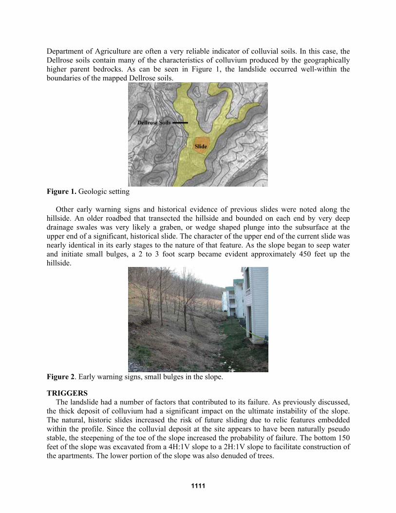
Other early warning signs and historical evidence of previous slides were noted along the
hillside. An older roadbed that transected the hillside and bounded on each end by very deep drainage swales was very likely a graben, or wedge shaped plunge into the subsurface at the upper end of a significant, historical slide. The character of the upper end of the current slide was nearly identical in its early stages to the nature of that feature. As the slope began to seep water and initiate small bulges, a 2 to 3 foot scarp became evident approximately 450 feet up the hillside.
Figure 2. Early warning signs, small bulges in the slope. TRIGGERS
The landslide had a number of factors that contributed to its failure. As previously discussed, the thick deposit of colluvium had a significant impact on the ultimate instability of the slope. The natural, historic slides increased the risk of future sliding due to relic features embedded within the profile. Since the colluvial deposit at the site appears to have been naturally pseudo stable, the steepening of the toe of the slope increased the probability of failure. The bottom 150 feet of the slope was excavated from a 4H:1V slope to a 2H:1V slope to facilitate construction of the apartments. The lower portion of the slope was also denuded of trees.
1111
As frequently is the case, water played a very important role in the loss of stability. The winter precipitation was above normal and the local colluvium absorbs water rather quickly but doesn’t discharge it as readily. This causes an increase in weight of the sliding mass and a decrease in shear strength, decreasing the factor of safety of the slope. In addition, the downward sloping strata created by the method of deposition contribute to the easier development of slide planes. Moreover, the previous repair work actually exacerbated the problem rather than helping it. These zones of shot rock buried in the slope created permeable pockets that readily filled with subsurface water, added to the weight and allowed the infiltration to penetrate deeper into the subsurface soils. Also, a diversion ditch constructed at the top of the cleared area was so flat that it actually retained water rather than discharging it. On or around the week of May 11, 2003, over 10 inches of rain was recorded in the area. The slide had already begun moving, but the large volume of available water and the considerable inflow into the open tension cracks rapidly accelerated the movement of the slide.
ANALYSIS
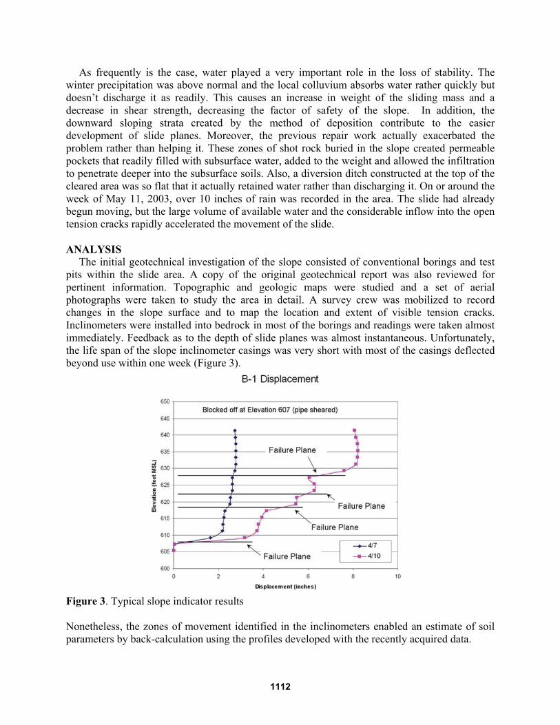
The initial geotechnical investigation of the slope consisted of conventional borings and test pits within the slide area. A copy of the original geotechnical report was also reviewed for pertinent information. Topographic and geologic maps were studied and a set of aerial photographs were taken to study the area in detail. A survey crew was mobilized to record changes in the slope surface and to map the location and extent of visible tension cracks. Inclinometers were installed into bedrock in most of the borings and readings were taken almost immediately. Feedback as to the depth of slide planes was almost instantaneous. Unfortunately, the life span of the slope inclinometer casings was very short with most of the casings deflected beyond use within one week (Figure 3).
Figure 3. Typical slope indicator results Nonetheless, the zones of movement identified in the inclinometers enabled an estimate of soil parameters by back-calculation using the profiles developed with the recently acquired data.
1112

Subsequent to the development of probable failure surfaces, a series of options was developed:
• Do Nothing (demolish the buildings and nominally stabilize the slope) • Move Buildings (nominally stabilize the slope) • Excavate Slide Material/Replace with Engineered Fill • Excavate to Construct a Shot rock Buttress • Gravity Retaining Walls • Deep Vertical Drains • Soldier Beam and Lagging Wall(s) • Reticulated Micropile Wall(s) • Soil Nails • Ground Anchors
Once the apparent magnitude of the slide was established and the likely degree of repair required, the ownership team performed its set of financial analyses to accompany the developing repair development. Cost/benefit calculations were performed to compare repair costs to the value of the units and length of time to recover the outlay of capital.
The evaluation of options was somewhat challenging due to the size and complexity of the team. The property was owned by an investment fund that was managed in New York City and had construction oversight out of its Chicago office. They retained peer review services from a geotechnical firm in Chicago. The fund’s principal stakeholder was located in the Middle East. The property management company was located in Atlanta with oversight from Baltimore and construction review from West Virginia. The contractor was located in Atlanta and their geotechnical designer was in Pittsburgh. The geotechnical firm providing data and options was located in Nashville. Additionally, the slide crossed a property line onto a parcel owned by a local investment group. Needless to say, communications were at times complicated and sometimes slow.
PROPOSED SOLUTION
The initial plan was to stabilize the entire slope with ground anchors. The number and location of anchors was being developed as the slide began its accelerated movement. Consequently, the construction of a temporary soldier beam and lagging wall was initiated to slow the progress of the slide and protect the buildings until the ground anchors could be installed. Figure 4 illustrates the advancing slide materials during wall construction.
Figure 4. Soldier Beam and Lagging Wall
1113
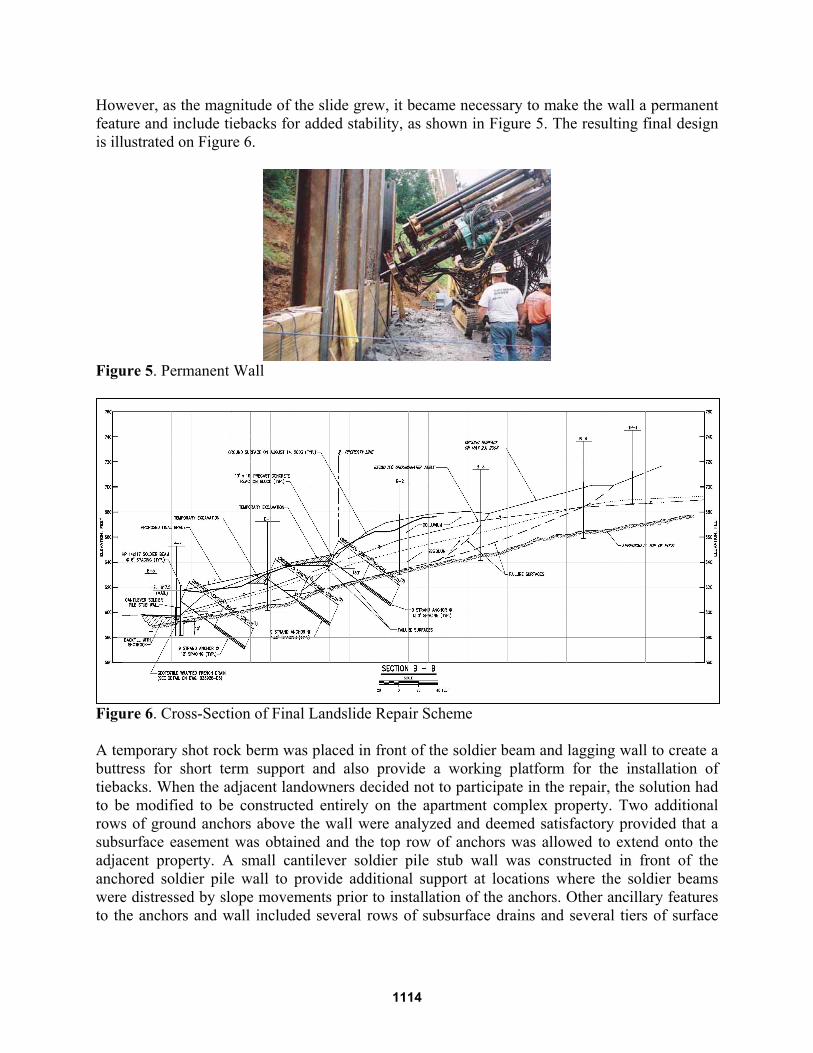
However, as the magnitude of the slide grew, it became necessary to make the wall a permanent feature and include tiebacks for added stability, as shown in Figure 5. The resulting final design is illustrated on Figure 6.
Figure 5. Permanent Wall
Figure 6. Cross-Section of Final Landslide Repair Scheme A temporary shot rock berm was placed in front of the soldier beam and lagging wall to create a buttress for short term support and also provide a working platform for the installation of tiebacks. When the adjacent landowners decided not to participate in the repair, the solution had to be modified to be constructed entirely on the apartment complex property. Two additional rows of ground anchors above the wall were analyzed and deemed satisfactory provided that a subsurface easement was obtained and the top row of anchors was allowed to extend onto the adjacent property. A small cantilever soldier pile stub wall was constructed in front of the anchored soldier pile wall to provide additional support at locations where the soldier beams were distressed by slope movements prior to installation of the anchors. Other ancillary features to the anchors and wall included several rows of subsurface drains and several tiers of surface
1114
ditches to divert water around the repaired area. In addition, the surface drainage in front the wall was considerably improved.
EMERGENCY RESPONSE
During the evaluation phase while the ownership considered their options, the landslide continued to move in response to frequent rainfall events. The magnitude of movement appeared to be in nearly direct correlation to the magnitude of precipitation. For about two weeks, the slide moved between a few inches and a foot per day. During this period the apartment staff removed appliances and other valuable objects from the ground floor units, and in the case of one building, from all three floors. As the slide advanced toward the buildings, minimal excavation was performed to maintain surface water drainage behind the buildings. Following some increased rain in the first part of May, movement increased; causing an active slide of about 6 acres, and the grading contractor mobilized his crew on Sunday morning, May 11 (Mother’s Day). Several pieces of tracked excavation equipment and a small fleet of dump trucks were delivered to the site to begin several days of 24-hours per day excavation to save the buildings. Rock was hauled in to create stable haul roads as mud and excavated slide materials were hauled out to create access to work. During this time, the slide movement increased to about 25 feet per day. The contractor had his eye on the slide and everyone else had theirs on the weather forecast.
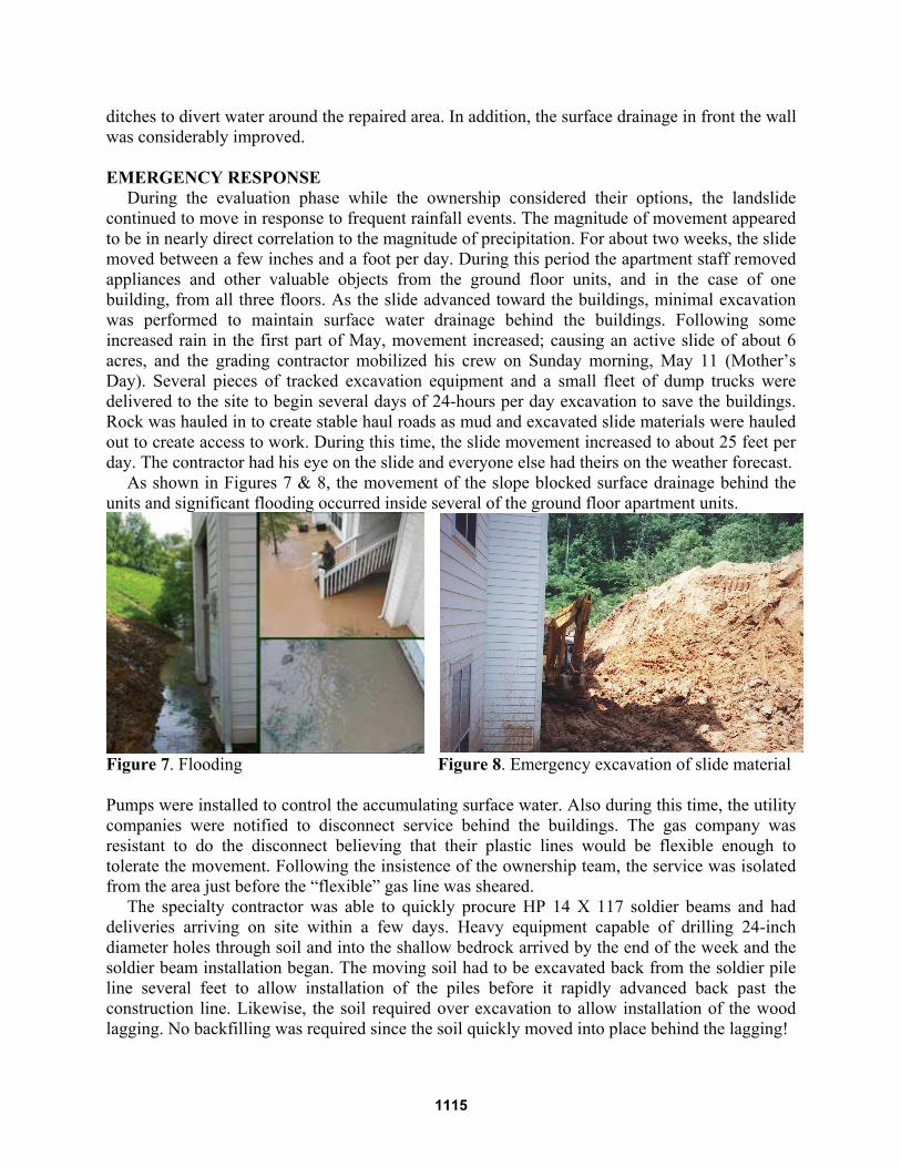
As shown in Figures 7 & 8, the movement of the slope blocked surface drainage behind the units and significant flooding occurred inside several of the ground floor apartment units.
Figure 7. Flooding Figure 8. Emergency excavation of slide material Pumps were installed to control the accumulating surface water. Also during this time, the utility companies were notified to disconnect service behind the buildings. The gas company was resistant to do the disconnect believing that their plastic lines would be flexible enough to tolerate the movement. Following the insistence of the ownership team, the service was isolated from the area just before the “flexible” gas line was sheared.
The specialty contractor was able to quickly procure HP 14 X 117 soldier beams and had deliveries arriving on site within a few days. Heavy equipment capable of drilling 24-inch diameter holes through soil and into the shallow bedrock arrived by the end of the week and the soldier beam installation began. The moving soil had to be excavated back from the soldier pile line several feet to allow installation of the piles before it rapidly advanced back past the construction line. Likewise, the soil required over excavation to allow installation of the wood lagging. No backfilling was required since the soil quickly moved into place behind the lagging!
1115

DESIGN The design process required consideration of the progressive failure (Figure 9) that was
occurring in the slope.
Figure 9. Surface expression of progressive failure Analysis was additionally complicated by the changing geometry of the slope as it moved downslope. The interim profile presented in Figure 10 illustrates some of the subsidence in progress in the higher elevations with corresponding bulging occurring in the lower slope.
Figure 10. One of the many profiles of the slope geometry developed as the slide progressed The most effective parameters used for analysis were derived from back calculation using the location of the slide plane from the inclinometers and the slide surfaces exposed in the construction, such as the failure surface seen in Figure 11.
1116

Figure 11. Exposed Slide Plane The final parameters used for the design of the repair components are presented in Table 1. Water levels were extrapolated from the exploratory data.
Table 1. Design Parameters
Stratum Angle of Internal Friction, Φ
Cohesion; psf
Moist Unit Weight, γm
Saturated Unit Weight, γsat
Colluvium 27 degrees 0 115 psf 130 psf Slickensided Residual Soil
15.7 degrees (back calculated)
0 120 psf 130 psf
Limestone Bedrock
45 degrees 5000 170 psf 170 psf
As the initial slope model seemed to approximate the conditions observed in the field, loading
conditions were assessed for the design of the soldier beams, reaction blocks and the ground anchors. The slope stabilization system was designed to increase the forces resisting sliding by 30 per cent so as to increase the factor of safety of the slope from approximately 1.0 to 1.3. The required allowable horizontal resistance to be provided by the anchored reaction blocks and anchored soldier pile walls to achieve this goal was calculated to be 72 kips per linear foot. The anchors and soldier piles were designed to bond in the underlying limestone bedrock. Anchor length varied from about 70 feet to over 85 feet. Anchor design loads were on the order of 316 kips each.
As the design considered the several different loading conditions, features to control the subsurface water were designed and implemented. Several rows of subsurface drains were installed parallel to the slide. The subsurface drain intended for the base of the soldier beam and lagging wall was constructed in front of the wall because of the dangers to personnel and equipment due to the advancing slide.
CONSTRUCTION
Construction in front of and on a moving slide (occasionally rapidly moving) presented several challenges. Close coordination between the wall construction and the excavation was critical to construct each segment of wall in front of the slide. Similarly, coordinated excavation and lagging placement was required to successfully create the wall, especially in light of the narrow work area between the slide and the apartment buildings. During this time, the magnitude of lateral movement of the slide was vivid illustrated when one of the inclinometer casings was
1117

excavated from between the soldier beams. The casing had originally been installed over 100 feet upslope of the anchored soldier pile wall.
The presence of the existing apartment buildings presented a unique opportunity to observe and modify the design and construction “on the fly”. An available internet connection allowed a webcam with pan and zoom capability to be installed high on one of the buildings which provided observation and communication of conditions to anyone on the design team or a member of the ownership and property management team. In several instances, a person at the slide site could be in contact by cell phone to the designer and project manager to review a condition that could be observed remotely using the webcam. Even though the connection was severed several times due to either the slide movement or equipment contact, it was quickly repaired. Time lapse video also provided interesting data for observation and analysis.
The parking lot provided a convenient staging area for the equipment and materials. An assembly line for construction of pre-cast anchor blocks (Figure 12) and lagging panels supported the field activities behind the buildings.
Figure 12. Finished Anchor Blocks Some of the vacant apartments (safely located in nearby structures) were used as construction offices and for housing of the construction personnel.
The emergency excavation of slide material and the importation of shot rock took its toll on the roads and parking lot in the complex. Over 2000 loads of earth were hauled off site and nearly 500 loads of shot rock were imported. The heavy axle loads were much higher than the design loads for the infrastructure. Consequently, additional cost was incurred to repave a significant portion of the complex as construction wound down. NON-TECHNICAL COMPLICATIONS
Design and construction is often complicated by factors that are non-technical. So, in addition to determining design parameters in a frequently changing environment, the final construction had to consider a number of non-technical factors. The landslide was massive; it incorporated approximately 6 acres, half of which occurred upslope on an adjacent landowner’s property. After several meetings, the adjacent landowner, whose property was adversely affected by the slide, chose not to participate in any repairs on his side of the property line even though he wanted to maintain the potential for upslope development. This meant that the apartments had to be protected by a repair that was constructed only on the lower half of the slope and that the design assumptions could change if and when the upslope property is developed. It also required that a subsurface easement be obtained to allow placement of some anchors as high as possible within the slide.
1118

As with many urban construction sites, the landslide remediation team had to deal with complaints about noise, dust, lights, etc. A fence was constructed around the construction zone to minimize intrusion by residents, and fall protection was required above the soldier beam and lagging wall to keep children from exploring around the wall.
Since the property was acquired as an investment, the potential for sale of the property was a possibility. In order to plan for the future sale, comprehensive records were maintained to document the decision trail and the design. That documentation proved to be very effective when used recently for a smooth sale of the property. POST-REPAIR MONITORING
In order to monitor the performance of the hillside subsequent to the remediation, another series of inclinometers were installed in the slope. These devices have been read with declining frequency and have demonstrated satisfactory post-construction performance. A less sophisticated early warning system was also installed to allow the groundskeeper or other non-technical staff to report basic levels of performance. Simply, several rows of steel fence posts were very accurately installed in the surface of the slope in straight alignment. A visual sighting along the rows of posts can indicate possible surface movement if the alignment changes. Based on recent observations, slope movements at the site have ceased.
CONCLUSIONS AND SUMMARY
The rapid movement of the landslide often required immediate communication and decisions amongst the property ownership, the designers and the construction personnel. The slope stabilization scheme was able to be constructed in the timely manner required to save the apartment buildings located near the toe of the slope. Installation of the web cam facilitated instant feedback on the status of the slope and visualization of construction hurdles by the remote team members to enable quick modifications to the design to accommodate the changing conditions. The repair scheme was designed to use materials that were available for immediate delivery at a reasonable cost and increase the slope’s resistance to sliding by 30 per cent. The slope repair scheme has been successful in stabilizing the slope and has allowed residents to occupy the affected apartment buildings.
1119